Old Dominion University ODU Digital Commons Engineering Technology Faculty Publications Engineering Technology 2012 Automation Laboratory Development Focusing on Industrial Hands-on Experience, Simulation Soſtware, and Application Research Projects Cheng Y. Lin Old Dominion University, [email protected]John R. Hackworth Old Dominion University, [email protected]Follow this and additional works at: hps://digitalcommons.odu.edu/engtech_fac_pubs Part of the Computer Engineering Commons , and the Engineering Education Commons is Conference Paper is brought to you for free and open access by the Engineering Technology at ODU Digital Commons. It has been accepted for inclusion in Engineering Technology Faculty Publications by an authorized administrator of ODU Digital Commons. For more information, please contact [email protected]. Repository Citation Lin, Cheng Y. and Hackworth, John R., "Automation Laboratory Development Focusing on Industrial Hands-on Experience, Simulation Soſtware, and Application Research Projects" (2012). Engineering Technology Faculty Publications. 99. hps://digitalcommons.odu.edu/engtech_fac_pubs/99 Original Publication Citation Lin, C. Y., & Hackworth, J. R. (2012). Automation laboratory development focusing on industrial hands-on experience, simulation soſtware, and application research projects. Paper presented at the 2012 ASEE Annual Conference and Exposition, San Antonio, Texas.
Automation Laboratory Development Focusing onIndustrial Hands-on Experience, SimulationSoftware, and Application Research ProjectsCheng Y. LinOld Dominion University, [email protected]
Follow this and additional works at: https://digitalcommons.odu.edu/engtech_fac_pubs
Part of the Computer Engineering Commons, and the Engineering Education Commons
This Conference Paper is brought to you for free and open access by the Engineering Technology at ODU Digital Commons. It has been accepted forinclusion in Engineering Technology Faculty Publications by an authorized administrator of ODU Digital Commons. For more information, pleasecontact [email protected].
Repository CitationLin, Cheng Y. and Hackworth, John R., "Automation Laboratory Development Focusing on Industrial Hands-on Experience,Simulation Software, and Application Research Projects" (2012). Engineering Technology Faculty Publications. 99.https://digitalcommons.odu.edu/engtech_fac_pubs/99
Original Publication CitationLin, C. Y., & Hackworth, J. R. (2012). Automation laboratory development focusing on industrial hands-on experience, simulation software,and application research projects. Paper presented at the 2012 ASEE Annual Conference and Exposition, San Antonio, Texas.
Cheng Lin is a professor and Program Director of mechanical engineering technology at Old DominionUniversity. He received his Ph.D. of mechanical engineering from Texas A&M University in 1989, and isa registered Professional Engineer in Virginia. Lin has expertise in automation control, machine design,CAD/CAM, CNC, geometric dimensioning, and tolerancing, and robotics. He has published 16 journalpapers in the areas of robotics, automation, and GD&T. He has been active in the technology applicationresearch and teaching training courses for Virginia’s Applied Technology and Professional DevelopmentCenter (VATPDC).
Prof. John R. Hackworth, Old Dominion University
John Hackworth is an Associate Professor and Director of the electrical engineering technology programat Old Dominion University. He holds a B.S. degree in electrical engineering technology and a master’sof science degree in electrical engineering, both from Old Dominion University. Prior to joining theOld Dominion University faculty, Hackworth had approximately 20 years of industrial experience in testengineering and plant automation with General Electric Company. He is the co-author of two textbookswhich are currently in use by several electrical engineering technology programs at universities within theU.S.
Automation Laboratory Development Focusing on Industrial Hands-on Experience, Simulation Software, and Application Research Projects
Abstract
This paper describes the development of an Automation Control Lab in the Department of Engineering Technology at the University. The lab facility includes pneumatic actuators/sensors, electrical relays/switches, and Programmable Logic Controllers (PLC). The major goal of the development is to help students gain hands-on industrial experience by conducting simple projects during the lecture hours and more advanced projects during the lab hours. Simulation software is also applied to reduce implementation time when developing complicated pneumatic circuits and PLC programs. In addition, three examples of industrial automation projects using PLC from the Technology Application Center (TAC) are also introduced to students to enhance their knowledge of automation controls. Performance assessment is conducted for this development.
1. Introduction
To a large extent, hands-on skills are what separate the programs of engineering technology from engineering1. Various hands-on labs and projects have been developed for engineering technology students to maximize their learning capabilities2,3,4,5. As PLC technology has been robustly applied in the industry, both engineering and engineering technology programs have included this subject into their curricula6,7,8. While the use of the technology in design projects has been mentioned in other publications9, there is no paper emphasizing the use of projects in the lecture to help students gain the industrial hands-on experience, attract attention, and improve class performance. This paper discusses the development of an automation control lab to achieve the purpose. The course content of Automation and Controls offered in the Department of Engineering Technology at the University includes the following four main components:
(1) Pneumatic components and pneumatic circuit designs.(2) Feedback from electrical sensors and related hardwired electrical relay ladder
diagrams.(3) Programmable Logical Controllers (PLC) programming.(4) PLC research projects.
During the first quarter of the class, students learn to identify various pneumatic valves with their associated functions in pneumatic circuit design. Main pneumatic components included in the lectures and labs are air supply modules, directional control valves, quick exhausted valves, speed control valves, roller-activated sensors, and actuators. Topics also cover the numbering of components in the circuit diagram and determining the sizes of valves based on the design inputs or requirements. To help students gain industrial
Page 25.247.2
hands-on experience when conducting the projects, Festo10 pneumatic components are used. During the second quarter of the class, students learn the configuration of relay schematic ladder diagrams, basic gate logics, Boolean functions with De Morgan’s law11, electrical relays, electrical sensors, and actuators. Students are required to solve various logic programming and hardware wiring problems. The Festo Didactic components are also used, including electrical switches, relays, solenoid-activated valves, and sensors12. Figure 1 shows the flexibility in wire connection technology provided by the company.
Figure 112: Flexibility in Connection Technology
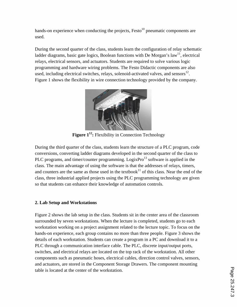
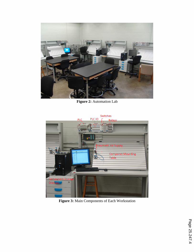
During the third quarter of the class, students learn the structure of a PLC program, code conversions, converting ladder diagrams developed in the second quarter of the class to PLC programs, and timer/counter programming. LogixPro13 software is applied in the class. The main advantage of using the software is that the addresses of relays, timers, and counters are the same as those used in the textbook11 of this class. Near the end of the class, three industrial applied projects using the PLC programming technology are given so that students can enhance their knowledge of automation controls. 2. Lab Setup and Workstations Figure 2 shows the lab setup in the class. Students sit in the center area of the classroom surrounded by seven workstations. When the lecture is completed, students go to each workstation working on a project assignment related to the lecture topic. To focus on the hands-on experience, each group contains no more than three people. Figure 3 shows the details of each workstation. Students can create a program in a PC and download it to a PLC through a communication interface cable. The PLC, discrete input/output ports, switches, and electrical relays are located on the top rack of the workstation. All other components such as pneumatic hoses, electrical cables, direction control valves, sensors, and actuators, are stored in the Component Storage Drawers. The component mounting table is located at the center of the workstation.
Page 25.247.3
Figure 2: Automation Lab
Figure 3: Main Components of Each Workstation
Page 25.247.4
Switches
3. Lecture Projects During each class, the instructor begins with an introductory lecture discussing a particular control topic, followed by an explanation of the project assignment. The remainder of the lab period is used by the students to construct and test their projects. Four typical projects given in each of the main teaching components, which is discussed in Session1, are listed as follows: 3.1 Pneumatic Circuit Design “When either one of the two normally closed 3/2 push buttons is pressed, or both are pressed, a single acting cylinder will be moving forward with an adjustable speed and retracting with a regular speed.” 3.2 Hardwired Ladder Logic Programming “If a Normally-Open (NO) push button A is pressed and released immediately, an LED will be on and remain on. The LED can be reset by pressing a Normally-Closed (NC) push button.” 3.3 PLC Programming – Timer “When an NO Start button is pressed and keep holding for five seconds, an output light will be on and remain on even though the button is not pressed. When a second NO switch is pressed, the system will be reset and the whole program is ready for another cycle.” 3.4 PLC Programming – Timer and Counter “When an NO Start button is pressed and released four times, a single-acting cylinder will be moving forward. After five seconds, the cylinder will be automatically retracting and the system is ready for the repeat of another cycle.” Figure 4 shows a group working on the hardwired seal-in circuit stated in Section 3.2.
Page 25.247.5
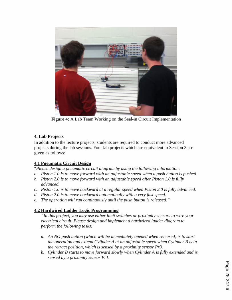
Figure 4: A Lab Team Working on the Seal-in Circuit Implementation
4. Lab Projects In addition to the lecture projects, students are required to conduct more advanced projects during the lab sessions. Four lab projects which are equivalent to Session 3 are given as follows: 4.1 Pneumatic Circuit Design “Please design a pneumatic circuit diagram by using the following information: a. Piston 1.0 is to move forward with an adjustable speed when a push button is pushed. b. Piston 2.0 is to move forward with an adjustable speed after Piston 1.0 is fully
advanced. c. Piston 1.0 is to move backward at a regular speed when Piston 2.0 is fully advanced. d. Piston 2.0 is to move backward automatically with a very fast speed. e. The operation will run continuously until the push button is released.” 4.2 Hardwired Ladder Logic Programming
“In this project, you may use either limit switches or proximity sensors to wire your electrical circuit. Please design and implement a hardwired ladder diagram to perform the following tasks: a. An NO push button (which will be immediately opened when released) is to start
the operation and extend Cylinder A at an adjustable speed when Cylinder B is in the retract position, which is sensed by a proximity sensor Pr3.
b. Cylinder B starts to move forward slowly when Cylinder A is fully extended and is sensed by a proximity sensor Pr1. P
age 25.247.6
c. Cylinder A remains in fully extended position, but when Cylinder B is fully extended and is sensed by a proximity sensor Pr2, Cylinder A starts to retract at regular speed.
d. Cylinder B remains in fully extended position, but when Cylinder A starts to retract, so does Cylinder B.
e. The operation will be continuously repeated until another NC Push Button is pressed.”
4.3 PLC Programming – Timer and Counter “Please design a safety PLC program for a chemical plant to perform the following operations:
a. An NO start button is used to activate the whole system and an NC reset button to reset the system at any time.
b. When an NO pressure gage is activated three times (Counter CTU-1) in 10 seconds, a red light will be on.
c. Both timer and counter will be automatically reset when they reach the preset value.”
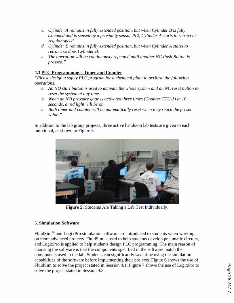
In addition to the lab group projects, three active hands-on lab tests are given to each individual, as shown in Figure 5.
Figure 5: Students Are Taking a Lab Test Individually.
5. Simulation Software FluidSim14 and LogixPro simulation software are introduced to students when working on more advanced projects. FluidSim is used to help students develop pneumatic circuits, and LogixPro is applied to help students design PLC programming. The main reason of choosing the software is that the components specified in the software match the components used in the lab. Students can significantly save time using the simulation capabilities of the software before implementing their projects. Figure 6 shows the use of FluidSim to solve the project stated in Session 4.1; Figure 7 shows the use of LogixPro to solve the project stated in Session 4.3.
Page 25.247.7
Figure 6: A Pneumatic Circuit Design Using FluidSim
Page 25.247.8
Figure 7: A PLC Program Using LogixPro 6. Three Industrial Automation Projects To help students gain the knowledge of automation controls using PLC programming, three industrial applied projects are introduced in the class: 6.1 A Pneumatically-Latched Valve15
Figures 8 and 9 show a design and fabrication of a single 5/2 (five ports and two positions) pneumatically-latched valve to automatically lift a cover. Operation of the design utilizes only through mechanical means without using any electrical power, electronic sensors, and controllers. Therefore, the system not only saves energy and components but also increases operational safety. Figure 8 shows that the valve stays in the retracted position; Figure 9 shows that the valve moves to the extended position.
Position Bolock ~ . ~ Bellow Foot-Alf The Retracting
Force Pushes the Spool against the Posirian Block
for Forward motion
Pump
... ...
Compressed Air
Retract P osirian
Retract PositiO!l.
ar Rack
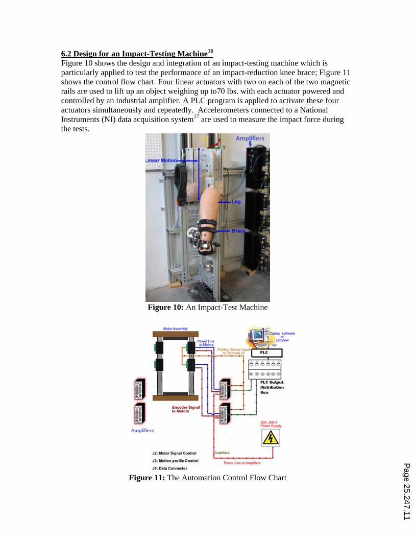
6.2 Design for an Impact-Testing Machine16 Figure 10 shows the design and integration of an impact-testing machine which is particularly applied to test the performance of an impact-reduction knee brace; Figure 11 shows the control flow chart. Four linear actuators with two on each of the two magnetic rails are used to lift up an object weighing up to70 lbs. with each actuator powered and controlled by an industrial amplifier. A PLC program is applied to activate these four actuators simultaneously and repeatedly. Accelerometers connected to a National Instruments (NI) data acquisition system17 are used to measure the impact force during the tests.
Figure 10: An Impact-Test Machine
Figure 11: The Automation Control Flow Chart
Page 25.247.11
Amplifiers
JZ: Molor Signal Control
.13: Mollon promo cont rol
J4: Oata Connoetor
2~ZOIIV "-Supply
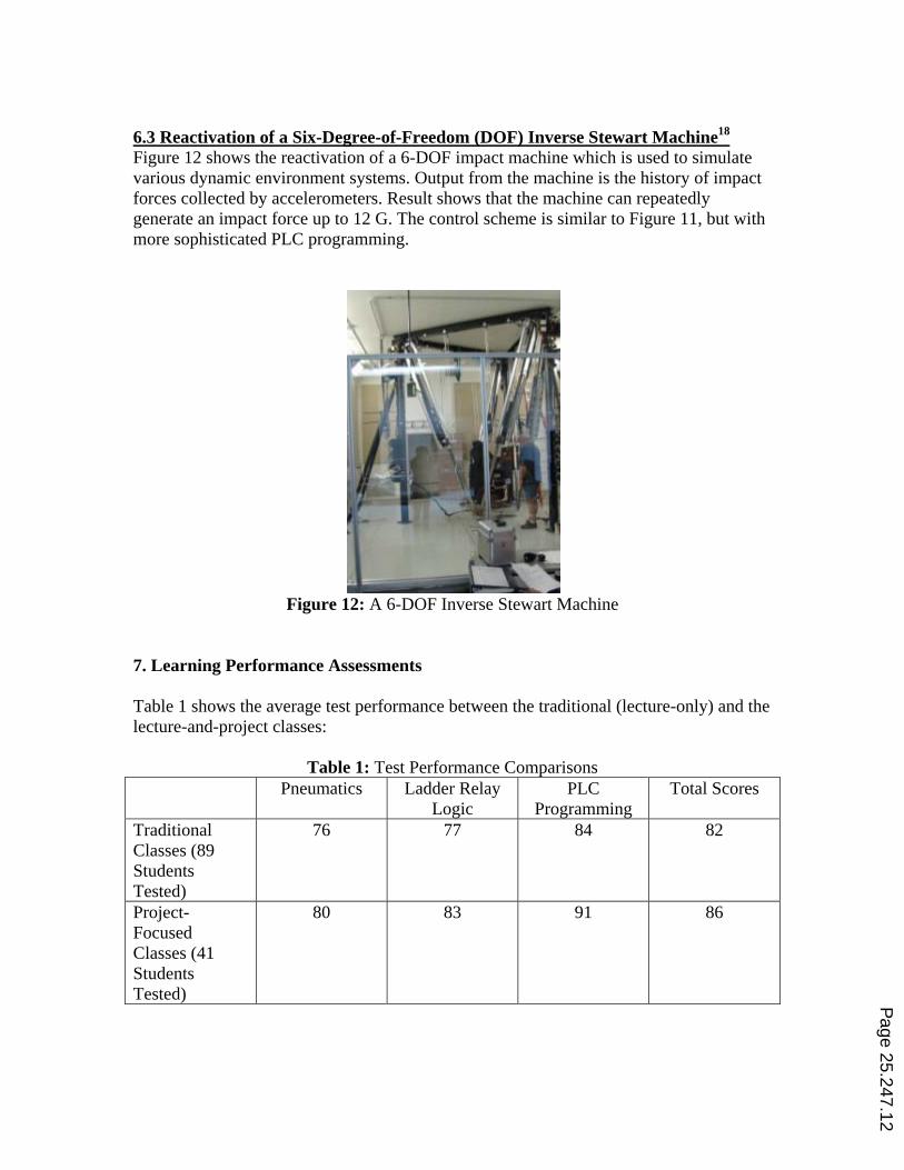
6.3 Reactivation of a Six-Degree-of-Freedom (DOF) Inverse Stewart Machine18
Figure 12 shows the reactivation of a 6-DOF impact machine which is used to simulate various dynamic environment systems. Output from the machine is the history of impact forces collected by accelerometers. Result shows that the machine can repeatedly generate an impact force up to 12 G. The control scheme is similar to Figure 11, but with more sophisticated PLC programming.
Figure 12: A 6-DOF Inverse Stewart Machine
7. Learning Performance Assessments Table 1 shows the average test performance between the traditional (lecture-only) and the lecture-and-project classes:
Table 1: Test Performance Comparisons Pneumatics Ladder Relay
Logic PLC
Programming Total Scores
Traditional Classes (89 Students Tested)
76 77 84 82
Project-Focused Classes (41 Students Tested)
80 83 91 86
Page 25.247.12
Results show that the test performance using this new approach is better than that of the traditional classes. Based on the instructors’ observations, two of the most obvious results of implementing the lecture/lab improvement are:
a. Higher class attendance rate: Students will have to come to the class for the lab-work credits performed in the lecture classes.
b. Stronger interest in coming to the class: Students pay more attention to the lecture topics and are willing to spend more time after the class to complete the projects.
Table 2: Questionnaires for Student Teaching Evaluation
1 IN THE FIRST WEEK OF CLASS, THE INSTRUCTOR PROVIDED DOCUMENTS AND INFORMATION THAT CLEARLY EXPLAINED THE COURSE CONTENT, ASSIGNMENTS, GRADING AND OTHER IMPORTANT POLICIES.
9 OVERALL, I HAVE LEARNED OR BENEFITED FROM THIS CLASS.
2 THE COURSE MATERIALS, EXAMS, PROJECTS AND/OR PAPERS IN THE CLASS REQUIRED ME TO THINK CRITICALLY.
10 OVERALL, THE INSTRUCTOR IS AN EFFECTIVE TEACHER.
3 THE INSTRUCTOR WELCOMED QUESTIONS AND OTHER CLASS PARTICIPATION.
11 RATE THE PUNCTUALITY OF THE INSTRUCTOR IN RETURNING STUDENT ASSIGNMENTS & EXAMS.
4 THE INSTRUCTOR WAS ENTHUSIASTIC WITH RESPECT TO THE SUBJECT MATTER.
12 RATE THE PUNCTUALITY OF THE INSTRUCTOR IN RETURNING STUDENT ASSIGNMENTS & EXAMS.
5 THE INSTRUCTOR WAS AVAILABLE FOR CONSULTATION AND HELPFUL DURING OFFICE HOURS.
13 RATE THE PUNCTUALITY OF THE INSTRUCTOR IN RETURNING STUDENT ASSIGNMENTS & EXAMS.
6 THE INSTRUCTOR ARRIVED ON TIME FOR CLASS AND USED THE FULL CLASS PERIOD ALLOTED.
14 RATE THE RELEVANCE OF THE EXAMS & PROJECTS USED TO ASSIGN GRADES IN THIS COURSE.
7 IN ORDER TO GET GOOD GRADES ON TESTS AND ASSIGNMENTS, I HAD TO KNOW THE COURSE MATERIALS OUTLINED IN THE SYLLABUS AND DISCUSSED IN CLASS
15 RATE THE FAIRNESS OF THE INSTRUCTOR IN ASSIGNING GRADES.
8 THE INSTRUCTOR’S PRESENTATIONS WERE INFORMATIVE.
Table 2 shows the questionnaires for the Student Teaching Evaluation at the University, the class received an average of 4.9 out of 5.0 when compared to the averages of the Department (4.2) and College (4.2). Plans have been implemented to continue monitoring the results of future class performances. 8. Summary The automation laboratory is developed to conduct a project-based for a lecture. Results show that the test performance improves in all main topic areas when compared to a traditional class. The main reasons for the improvement are because of higher class attendance rate and stronger interest in conducting hands-on projects. Because of the interest in gaining hands-on experience, students are willing to spend extra time to complete their projects. As students need to take the lab tests individually, their hands-on acquired skills can be evaluated. Also students can use the simulation capabilities of the software to save the implementation time when working on more complex projects.
Page 25.247.13
References 1. M. Olumolade, “Maximizing student learning through hands-on activities in engineering
technology”, ASEE Annual Conference Proceedings, p 9587-9605, ASEE 2004 Annual Conference and Exposition
2. M. Ssemakula, “Introducing hands-on manufacturing experience to students”, ASEE Annual Conference Proceedings, p 6715-6721, 2002 ASEE Annual Conference and Exposition
3. R. Agarwala, T. Abdel-Salam, and M. Faruqi, “Introducing thermal and fluid systems to industrial engineering technology students with hands-on laboratory experience”, ASEE Annual Conference and Exposition, Conference Proceedings, 2007 ASEE Annual Conference and Exposition
4. D. Foroudastan, and I. Campbell, “Student projects: Hands-on experience with mechanical engineering technology”, ASEE Annual Conference and Exposition, Conference Proceedings, p 13293-13299, 2005 ASEE Annual Conference and Exposition, Conference Proceedings
5. R. Chen, D. Goodman, A. Isadian, and E. Cooney, “Teaching renewable energy through hands-on project-based learning for engineering technology students”, ASEE Annual Conference and Exposition, Conference Proceedings, 2010 ASEE Annual Conference and Exposition
6. R. Melendy, C. Hammequist, and M. Foster, “A Review Of Programmable Logic Controllers In Control Systems Education”, Trends in Mechanical Engineering II, 2010 ASEE Annual Conference & Exposition
7. J. Parker, “Introduction To Programmable Logic Controllers In A Mechanical Engineering Instrumentation Course”, Session 2366, ASEE Annual Conference and Exposition, Conference Proceedings, 2001 ASEE Annual Conference
8. S. Hsieh,”Design Of Web Based Ladder Logic Tool Kit For Programmable Logic Controller Education”, ASEE Annual Conference and Exposition, Conference Proceedings, 2001 ASEE Annual Conference
9. R. Pecen and L. Guo, “Student Design Projects In A Programmable Logic Controller (Plc) Course”, ASEE Annual Conference and Exposition, Conference Proceedings, 2008 ASEE Annual Conference
systems/?fbid=aW50LmVuLjU1Ny4xNy4xOS4zNDMz 13. “LogixPro 500”, http://www.theplctutor.com/logixpro.html 14. “Fluidsim”, http://www.festo-didactic.com/int-en/learning-systems/software-e-learning/fluidsim/ 15. C. Lin, “Design of a Pneumatic Valve for an Automatic Seat Lifting or
Door Opening Mechanism”, ASEE Annual Conference, Session 1149, Louisville, KY, June 2010 16. C. Lin, Hou, G., Bawab, S., Coates, T., Hassar, H., and Liu, Y., “System Design and Integration
for Repeated Impact Tests”, ASEE Annual Conference, Session 2556, Austin, TX, June 2009 17. “NI USB-6251”, http://sine.ni.com/nips/cds/view/p/lang/en/nid/202597 18. C. Lin, “Reactivation of a Six-Degree-of-Freedom Repeated Impact
Machine Using Programmable Logical Controller (PLC)”, ASEE Annual Conference, AC 2011-663, Vancouver, Canada, June 2011