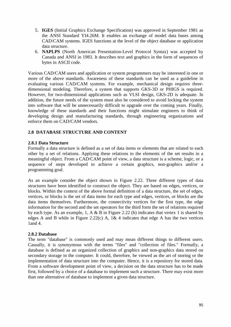
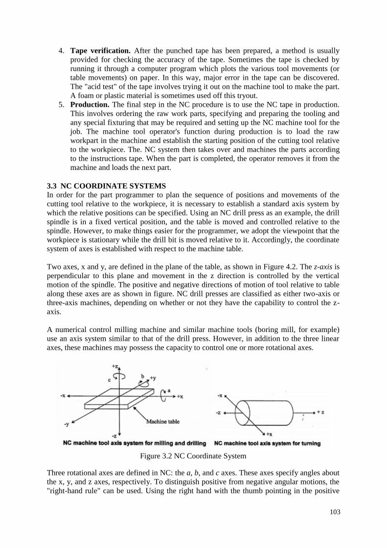
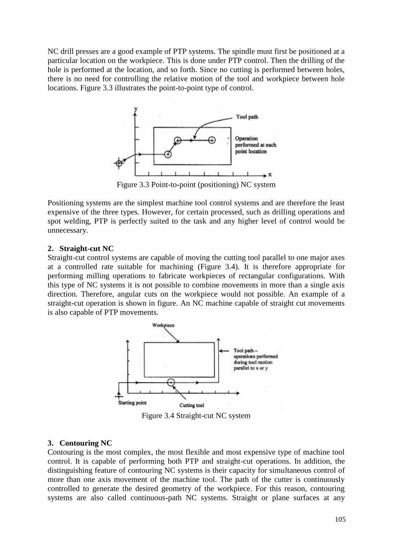
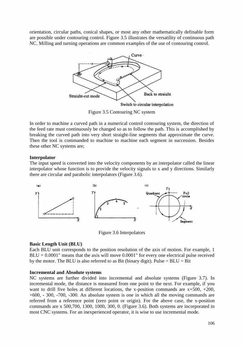
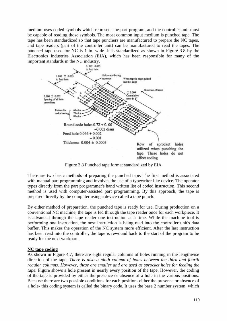
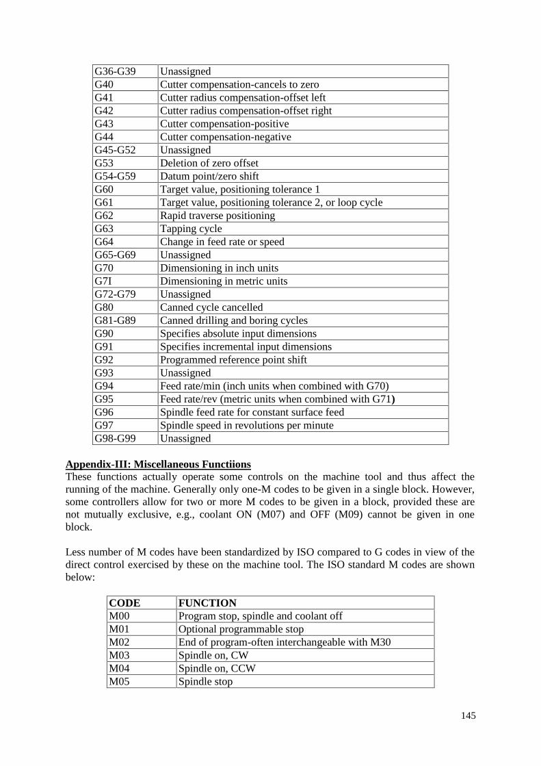
1 AUTOMATION & NUMERICAL CONTROL MACHINES 1.0 AUTOMATION IN MANUFACTURING MODULE-I Automation is the technology by which a process or procedure is accomplished without human assistance. It is implemented using a program of instructions combined with a control system that executes the instructions. To automate a process, power is required, both to drive the process itself and to operate the program and control system. Although automation can be applied in a wide variety of areas, it is most closely associated with the manufacturing industries. Automated manufacturing systems operate in the factory on the physical product. They perform operations such as processing, assembly, inspection, or material handling, in some cases accomplishing more than one of these operations in the same system. They are called automated because they perform their operations with a reduced level of human participation compared with the corresponding manual process. In some highly automated systems, there is virtually no human participation. Examples of automated manufacturing systems include: • automated machine tools that process parts • transfer lines that perform a series of machining operations • automated assembly systems • manufacturing systems that use industrial robots to perform processing or assembly operations • automatic material handling and storage systems to integrate manufacturing operations • automatic inspection systems for quality control Thus, Automation is a technology concerned with the application of mechanical, electronic, and computer-based systems to operate and control production. This technology includes: • Automatic machine tools to process parts • Automatic assembly machines • Industrial robots • Automatic material handling and storage systems • Automatic inspection systems for quality control • Feedback control and computer process control • Computer systems for planning, data collection, and decision making to support manufacturing activities 1.1 ELEMENTS OF AUTOMATED SYSTEM An automated system consists of three basic elements: (1) power to accomplish the process and operate the system. (2) a program of instructions to direct the process, and (3) a control system to actuate the instructions. The relationship amongst these elements is illustrated in Figure 1.1. All systems that qualify as being automated include these three basic elements in one form or another.
Transcript
1
AUTOMATION & NUMERICAL CONTROL MACHINES
1.0 AUTOMATION IN MANUFACTURING MODULE-I
Automation is the technology by which a process or procedure is accomplished withouthuman assistance. It is implemented using a program of instructions combined with a controlsystem that executes the instructions. To automate a process, power is required, both to drivethe process itself and to operate the program and control system. Although automation can beapplied in a wide variety of areas, it is most closely associated with the manufacturingindustries.
Automated manufacturing systems operate in the factory on the physical product. Theyperform operations such as processing, assembly, inspection, or material handling, in somecases accomplishing more than one of these operations in the same system. They are calledautomated because they perform their operations with a reduced level of human participationcompared with the corresponding manual process. In some highly automated systems, thereis virtually no human participation. Examples of automated manufacturing systems include:
• automated machine tools that process parts• transfer lines that perform a series of machining operations• automated assembly systems• manufacturing systems that use industrial robots to perform processing or assembly
operations• automatic material handling and storage systems to integrate manufacturing
operations• automatic inspection systems for quality control
Thus, Automation is a technology concerned with the application of mechanical, electronic,and computer-based systems to operate and control production. This technology includes:
• Automatic machine tools to process parts• Automatic assembly machines• Industrial robots• Automatic material handling and storage systems• Automatic inspection systems for quality control• Feedback control and computer process control• Computer systems for planning, data collection, and decision making to support
manufacturing activities
1.1 ELEMENTS OF AUTOMATED SYSTEM
An automated system consists of three basic elements:(1) power to accomplish the process and operate the system.(2) a program of instructions to direct the process, and(3) a control system to actuate the instructions.
The relationship amongst these elements is illustrated in Figure 1.1. All systems that qualifyas being automated include these three basic elements in one form or another.
2
Figure 1.1 Elements of an automated system
(1) Power to accomplish the automated processAn automated system is used to operate some process, and power is required to drive theprocess as well as the controls. The principal source of power in automated systems iselectricity. Electric power has many advantages in automated as well as non-automatedprocesses
Electrical power is widely available at moderate cost. Electrical power can be readily converted to alternative energy forms: mechanical,
thermal, light, acoustic, hydraulic, and pneumatic. Electrical power at low levels can be used to accomplish functions such as signal,
transmission, information processing, and data storage and communication. Electrical energy can be stored in long-life batteries for use in locations where an
external source of electrical power is not conveniently available.
Power is required in automation for the followings: Processing operations Loading and unloading the work unit Material transport between operations Controller unit Power to actuate the control signals Data acquisition and information processing
(2) Program of InstructionsThe actions performed in an automated process are defined by a program of instructions.Each part or product style made in the operation requires one or more processing steps thatare unique to that style, These processing steps are performed during a work cycle. A newpart is completed during each work cycle (in some manufacturing operations, more than onepart is produced during the work cycle; e.g., a plastic injection molding operation mayproduce multiple parts each cycle using a multiple cavity mold). The particular processingsteps for the work cycle are specified in a work cycle program.
Work Cycle Programs. In the simplest automated processes, the work cycle consists ofessentially one step, which is to maintain a single process parameter at a defined level.However, the system becomes complicated when the process involves a work cycleconsisting of multiple steps with more number of process parameters are required to becontrolled. Most discrete part manufacturing operations are in this category.
3
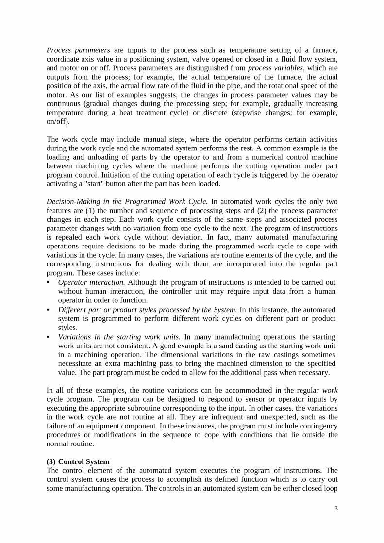
Process parameters are inputs to the process such as temperature setting of a furnace,coordinate axis value in a positioning system, valve opened or closed in a fluid flow system,and motor on or off. Process parameters are distinguished from process variables, which areoutputs from the process; for example, the actual temperature of the furnace, the actualposition of the axis, the actual flow rate of the fluid in the pipe, and the rotational speed of themotor. As our list of examples suggests, the changes in process parameter values may becontinuous (gradual changes during the processing step; for example, gradually increasingtemperature during a heat treatment cycle) or discrete (stepwise changes; for example,on/off).
The work cycle may include manual steps, where the operator performs certain activitiesduring the work cycle and the automated system performs the rest. A common example is theloading and unloading of parts by the operator to and from a numerical control machinebetween machining cycles where the machine performs the cutting operation under partprogram control. Initiation of the cutting operation of each cycle is triggered by the operatoractivating a "start" button after the part has been loaded.
Decision-Making in the Programmed Work Cycle. In automated work cycles the only twofeatures are (1) the number and sequence of processing steps and (2) the process parameterchanges in each step. Each work cycle consists of the same steps and associated processparameter changes with no variation from one cycle to the next. The program of instructionsis repealed each work cycle without deviation. In fact, many automated manufacturingoperations require decisions to be made during the programmed work cycle to cope withvariations in the cycle. In many cases, the variations are routine elements of the cycle, and thecorresponding instructions for dealing with them are incorporated into the regular partprogram. These cases include: Operator interaction. Although the program of instructions is intended to be carried out
without human interaction, the controller unit may require input data from a humanoperator in order to function.
Different part or product styles processed by the System. In this instance, the automatedsystem is programmed to perform different work cycles on different part or productstyles.
Variations in the starting work units. In many manufacturing operations the startingwork units are not consistent. A good example is a sand casting as the starting work unitin a machining operation. The dimensional variations in the raw castings sometimesnecessitate an extra machining pass to bring the machined dimension to the specifiedvalue. The part program must be coded to allow for the additional pass when necessary.
In all of these examples, the routine variations can be accommodated in the regular workcycle program. The program can be designed to respond to sensor or operator inputs byexecuting the appropriate subroutine corresponding to the input. In other cases, the variationsin the work cycle are not routine at all. They are infrequent and unexpected, such as thefailure of an equipment component. In these instances, the program must include contingencyprocedures or modifications in the sequence to cope with conditions that lie outside thenormal routine.
(3) Control SystemThe control element of the automated system executes the program of instructions. Thecontrol system causes the process to accomplish its defined function which is to carry outsome manufacturing operation. The controls in an automated system can be either closed loop
4
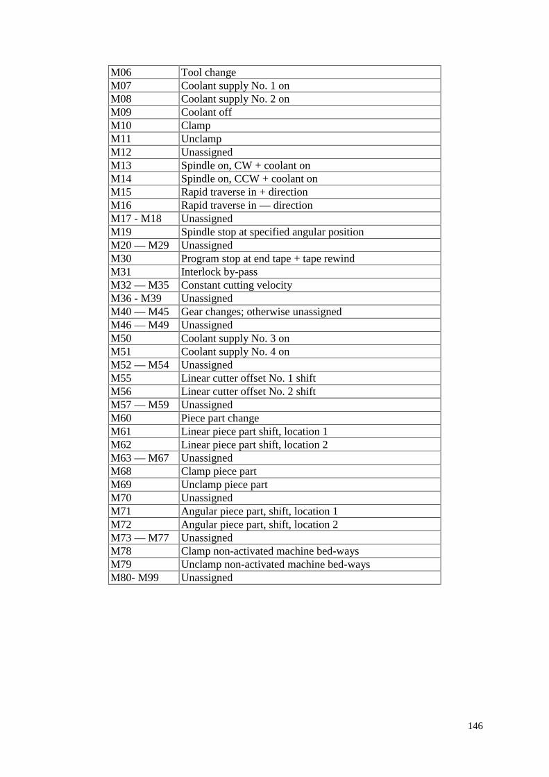
or open loop. A closed loop control system, also known as a feedback control system is one inwhich the output variable is compared with an input parameter, and any difference betweenthe two is used to drive the output into agreement with the input. As shown in Figure 1.2, aclosed loop control system consists of six basic elements: (1) input parameter, (2) process, (3)output variable, (4) feedback sensor. (5) controller and (6) actuator.
Figure 1.2 A feedback control system
The input parameter often referred to as the set point, represents the desired value of theoutput. The process is the operation or function being controlled. In particular, it is the outputvariable that is being controlled in the loop. A sensor is used to measure the output variableand close the loop between input and output. Sensors perform the feedback function in aclosed loop control system. The controller compares the output with the input and makes therequired adjustment in the process to reduce the difference between them. The adjustment isaccomplished using one or more actuators, which are the hardware devices that physicallycarry out the control actions, such as an electric motor or a flow valve. The model in Figure 2shows only one loop, however, most industrial processes require multiple loops, one for eachprocess variable that must be controlled
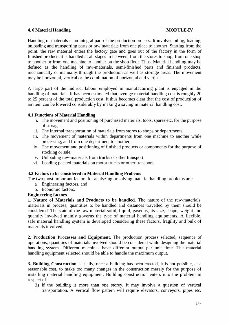
In contrast to the closed loop control system, an open loop control system operates withoutthe feedback loop, as in Figure 1.3. In this case, the controls operate without measuring theoutput variable so no comparison is made between the actual value of the output and thedesired input parameter. The controller relies on an accurate model of the effect of itsactuator on the process variable. With an open loop system, there is always the risk that theactuator will not have the intended effect on the process, and that is the disadvantage of anopen loop system. Its advantage is that it is generally simpler and less expensive than a closedloop system. Open loop systems are usually appropriate when the following conditions apply:(1) The actions performed by the control system are simple, (2) the actuating function is veryreliable, and (3) any reaction forces opposing the actuation are small enough to have no effecton the actuation. If these characteristics are not applicable, then a closed loop control systemmay be more appropriate.
Figure 1.3 An open loop control system
5
1.3 ADVANCED AUTOMATION FUNCTIONSIn addition to executing work cycle programs, an automated system may be capable ofexecuting advanced functions that are not specific to a particular work unit. In general, thefunctions are concerned with enhancing the performance and safety of the equipment.Advanced automation functions include the following: (1) safety monitoring, (2) maintenanceand repair diagnostics, and (3) error detection and recovery.
Advanced automation functions are made possible by special subroutines included in theprogram of instructions. In some cases, the functions provide information only and do notinvolve any physical actions by the control system. An example of this case includesreporting a list of preventive maintenance tasks that should be accomplished. Any actionstaken on the basis of this report are decided by the human operators and managers of thesystem and not by the system itself. In other cases, the program of instructions must bephysically executed by means of the control system using available actuators. A simpleexample of this case is a safety monitoring system that sounds an alarm when a humanworker gets dangerously close to the automated system.
(1) Safety MonitoringOne of the significant reasons for automating a manufacturing operation is to removeworker(s) from a hazardous working environment. An automated system is often installed toperform a potentially dangerous operation that would otherwise be accomplished manuallyby human workers. However, even in automated systems workers are still needed to servicethe system at periodic time intervals If not full-time. Accordingly, it is important that theautomated system be designed to operate safely when workers are in attendance. In additionit is essential that the automated system carry out its process in a way that is not self-destructive. Thus there are two reasons for providing an automated system with a safetymonitoring capability: (1) to protect human workers in the vicinity of the system and (2) toprotect the equipment associated with the system. It should be mentioned that a given safetymonitoring system is limited in its ability to respond to hazardous conditions by the possibleirregularities that have been foreseen by the system designer. If the designer has notanticipated a particular hazard, and consequently has not provided the system with thesensing capability to detect that hazard, then the safety monitoring system cannot recognizethe event if and when it occurs.
(2) Maintenance and Repair DiagnosticsModem automated production systems are becoming increasingly complex and sophisticated,thus complicating the problem of maintaining and repairing them. Maintenance and repairdiagnostics refers to the capabilities of an automated system to assist in the identification ofthe source of potential or actual malfunctions and failures of the system. Three modes ofoperation are typical of a modern maintenance and repair diagnostics subsystem. Status monitoring: In the status monitoring mode, the diagnostic subsystem monitors and
records the status of key sensors and parameters of the system during normal operation.On request, the diagnostics subsystem can display any of these values and provide aninterpretation of current system status, perhaps warning of an imminent failure.
Failure diagnostics: The failure diagnostics mode is invoked when a malfunction orfailure occurs. Its purpose is to interpret the current values of the monitored values and toanalyze the recorded values preceding the failure so that the cause of the failure can beidentified.
Recommendation of repair procedure: The subsystem provides a recommendedprocedure to the repair crew as to the steps that should be taken to effect repairs.
6
Methods for developing the recommendations are sometimes based on the use of expertsystems in which the collective judgments of many repair experts are pooled andincorporated into a computer program that uses artificial intelligence techniques.
Status monitoring serves two important functions in machine diagnostics: (1) providinginformation for diagnosing a current failure and (2) providing data to predict a futuremalfunction or failure. First, when a failure of the equipment has occurred, it is usuallydifficult for the repair crew to determine the reason for the failure and what steps should betaken to make repairs. It is often helpful to reconstruct the events leading up to the failure.The computer is programmed to monitor and record the variables and to draw logicalinferences from their values about the reason for the malfunction. This diagnosis helps therepair personnel make the necessary repairs and replace the appropriate components.
This is especially helpful in electronic repairs where it is often difficult to determine on thebasis of visual inspection which components have failed. The second function of statusmonitoring is to identify signs of an impending failure, so that the affected components canbe replaced before failure actually causes the system to go down. These part replacementscan be made during the night shift or other time when the process is not operating with theresult that the system experiences no loss of regular operation.
(3) Error Detection and recoveryIn the operation of any automated system, there are hardware malfunctions and unexpectedevents that occur during operation. These events can result in costly delays and loss ofproduction until the problem has been corrected and regular operation is restored.Traditionally equipment malfunctions are corrected by human workers, perhaps with the aidof maintenance and repair diagnostics subroutine. With the increased use of computer controlfor manufacturing processes, there is a trend toward using the control computer not only todiagnose the malfunctions but also to automatically take the necessary corrective action torestore the system to normal operation. The term error detection and recovery is used whenthe computer performs these functions,
Error Detection: As indicated by the term error detection and recovery consists of two steps:(1) error detection and (2) error recovery. The error defection step uses the automatedsystem's available sensor systems to determine when a deviation or malfunction has occurred,correctly interpret the sensor signal(s), and classify-the error. Design of the error detectionsubsystem must begin with the classification of the possible errors that can occur duringsystem operation. The errors in a manufacturing process tend to be very application specific.They must be anticipated in advance in order to select sensors that will enable their detection
In analyzing a given production operation, the possible errors can be classified into one ofthree general categories:
(1) random errors,(2) systematic errors, and(3) aberrations,
Random errors occur as a result of the normal stochastic nature of the process. These errorsoccur when the process is in statistical control. Large variations in part dimensions, evenwhen the production process is in statistical control, can cause problems in downstreamoperations. By detecting these deviations on a part-by-part basis, corrective action can betaken in subsequent operations.
7
Systematic errors are those that result from some assignable cause such as a change in rawmaterial properties or a drift in an equipment setting. These errors usually cause the productto deviate from specifications so as to be unacceptable in quality terms.
The third type of error aberrations, results from either an equipment failure or a humanmistake. Examples of equipment failures include fracture of a mechanical shear pin, bursts ina hydraulic line, rupture of a pressure vessel, and sudden failure of a cutting tool. Examplesof human mistakes include errors in the control program, improper fixture setups, andsubstitution of the wrong raw materials,
The two main design problems in error detection are: (1) to anticipate all of the possibleerrors that can occur in a given process and (2) to specify the appropriate sensor systems andassociated interpretive software so that the system is capable of recognizing each error.Solving the first problem requires a systematic evaluation of the possibilities under each ofthe three error classifications. If the error has not been anticipated, then the error detectionsubsystem cannot correctly detect and identify it.
Error recovery: It is concerned with applying the necessary corrective action to overcome theerror and bring the system back to normal operation. The problem of designing an errorrecovery system focuses on devising appropriate strategies and procedures that will eithercorrect or compensate for the variety of errors that can occur in the process. Generally, aspecific recovery strategy and procedure must be designed for each different error. The typesof strategies can be classified as follows:1. Make adjustments at the end of the current work cycle. When the current work cycle is
completed, the part program branches to a corrective action subroutine specificallydesigned for the error detected, executes the subroutine, and then returns to the workcycle program. This action reflects a low level of urgency and is most commonlyassociated with random errors in the process.
2. Make adjustments during the current cycle. This general1y indicates a higher level ofurgency than the preceding type. In this case, the action to correct or compensate for thedetected error is initiated as soon as the error is detected. However, it must be possible toaccomplish the designated corrective action while the work cycle is still being executed.
3. Stop the process to invoke corrective action. In this case, the deviation or malfunctionrequires that the execution of the work cycle be suspended during corrective action. It isassumed that the system is capable of automatically recovering from the error withouthuman assistance. At the end of the corrective action, the regular work cycle iscontinued.
4. Stop the process and call for help. In this case, the error requiring stoppage of theprocess that cannot be resolved through automated recovery procedures. This situationarises because: (1) the automated cell is not enabled to correct the problem or (2) theerror cannot be classified into the predefined list of errors. In either case, humanassistance is required to correct the problem and restore the system to fully automatedoperation.
Error detection and recovery requires an interrupt system. When an error in the process issensed and identified, an interrupt in the current program execution is invoked to branch tothe appropriate recovery subroutine, This is done either at the end of the current cycle (type 1above) or immediately (types 2, 3, and 4).At the completion of the recovery procedure,program execution reverts back to normal operation.
8
1.4 LEVELS OF AUTOMATION
The concept of automated systems can be applied to various levels of factory operations. Onenormally associates automation with the individual production machines. However, theproduction machine itself is made up of subsystems that may themselves be automated.
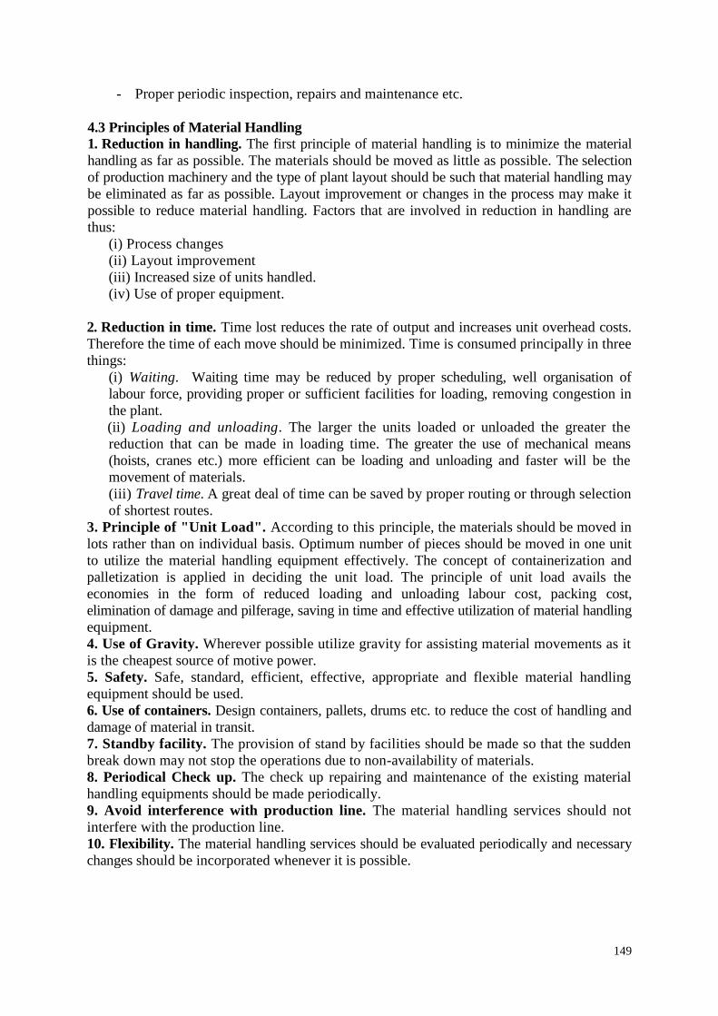
For example, a modern numerical control (NC) machine tool is an automated system.However, the NC machine itself is composed of multiple control systems. Similarly, a NCmachine is often part of a larger manufacturing system, and the larger system may itself beautomated. Thus there are various levels of automation is depicted in Figure 1.4.
Figure 1.4 Level of automation
1. Device level. This is the lowest level in automation hierarchy. It includes theactuators, sensors, and other hardware components that comprise the machine level.The devices are combined into the individual control loops of the machine; forexample, the feedback control loop for one axis of a CNC machine or one joint of anindustrial robot.
2. Machine level. Hardware at the device level is assembled into individual machines.Examples include CNC machine tools and similar production equipment, industrialrobots, powered conveyors, and automated guided vehicles. Control functions at thislevel include performing the sequence of steps in the program of instructions in thecorrect order and making sure that each step is properly executed.
3. Cell or system level. This is the manufacturing cell or system level, which operatesunder instructions from the plant level. A manufacturing cell or system is a group ofmachines or workstations connected and supported by a material handling system,computer and other equipment appropriate to the manufacturing process. Productionlines are included in this level. Likely functions include part dispatching and machineloading, coordination among machines and material handling system, and collectingand evaluating inspection data.
9
4. Plant level. This is the factory or production systems level. It receives instructionsfrom (he corporate information system and translates them into operational plans forproduction. Likely functions include: order processing, process planning, inventorycontrol, purchasing, material requirements planning, shop floor control, and qualitycontrol.
5. Enterprise level. This is the highest level consisting of the corporate informationsystem. It is concerned with all of the functions necessary to manage the company:marketing and sales, accounting, design, research, aggregate planning, and masterproduction scheduling.
1.5 TYPES OF AUTOMATION
Automated production systems are classified into three basic types:
Fixed automationFixed automation is a system in which the sequence of processing (or assembly) operations isfixed by the equipment configuration. The operations in the sequence are usually simple. It isthe integration and coordination of many such operations into one piece of equipment thatmakes the system complex. The typical features of fixed automation are:
• High initial investment for custom-engineered equipment• High production rates• Relatively inflexible in accommodating product changes
The economic justification for fixed automation is found in products with very high demandrates and volumes. The high initial cost of the equipment can be spread over a very largenumber of units, thus making the unit cost attractive compared to alternative methods ofproduction.
Programmable automationIn programmable automation, the production equipment is designed with the capability tochange the sequence of operations to accommodate different product configurations. Theoperation sequence is controlled by a program, which is a set of instructions coded so that thesystem can read and interpret them. New programs can be prepared and entered into theequipment to produce new products. Some of the features that characterize programmableautomation include:
• High investment in general-purpose equipment• Low production rates relative to fixed automation• Flexibility to deal with changes in product configuration• Most suitable for batch production
Automated production systems that are programmable are used in low and medium- volumeproduction. The parts or products are typically made in batches. To produce each new batchof a different product, the system must be reprogrammed with the set of machine instructionsthat correspond to the new product. The physical setup of the machine must also be changedover: Tools must be loaded, fixtures must be attached to the machine table, and the requiredmachine settings must be entered. This changeover procedure takes time. Consequently, the
10
typical cycle for a given product includes a period during which the setup andreprogramming takes place, followed by a period in which the batch is produced.
Flexible automationFlexible automation is an extension of programmable automation. The concept of flexibleautomation has developed only over the last 15 to 20 years, and the principles are stillevolving. A flexible automated system is one that is capable of producing a variety ofproducts (or parts) with virtually no time lost for changeovers from one product to the next.There is no production time lost while reprogramming the system and altering the physicalsetup (tooling, fixtures and machine settings). Consequently, the system can produce variouscombinations and schedules of products, instead of requiring that they be made in separatebatches. The features of flexible automation can be summarized as follows:
• High investment for a custom-engineered system• Continuous production of variable mixtures of products• Medium production rates• Flexibility to deal with product design variations
The essential features that distinguish flexible automation from programmable automationare (1) the capacity to change part programs with no lost production time, and (2) thecapability to change over the physical setup, again with no lost production time. Thesefeatures allow the automated production system to continue production without the downtimebetween batches that is characteristic of programmable automation. Changing the partprograms is generally accomplished by preparing the programs offline on a computer systemand electronically transmitting the programs to the automated production system. Therefore,the time required to do the programming for the next job does not interrupt production on thecurrent job. Changing the physical setup between parts is accomplished by making thechangeover offline and then moving it into place simultaneously as the next part comes intoposition for processing. The use of pallet fixtures that hold the parts and transfer into positionat the workplace is one way of implementing this approach. For these approaches to besuccessful, the variety of parts that can be made on a flexible automated production system isusually more limited than a system controlled by programmable automation.
The relative positions of the three types of automation for different productionvolumes and product varieties are depicted in Figure 1.5.
Figure 1.5 Types of automation as a function of volume of production verses product variety
11
1.6 REASONS FOR AUTOMATING
The important reasons for automating include the following:
1. Increased productivity: Automation of manufacturing operations holds the promise ofincreasing the productivity of labor. This means greater output per hour of labor input.Higher production rates (output per hour) are achieved with automation than with thecorresponding manual operations.
2. High cost of labor: The trend in the industrialized societies of the world has been towardever-increasing labor costs. As a result, higher investment in automated equipment hasbecome economically justifiable to replace manual operations. The high cost of labor isforcing business leaders to substitute machines for human labor. Because machines canproduce at higher rates of output, the use of automation results in a lower cost per unit ofproduct.
3. Labor shortages: In many advanced nations there has been a general shortage of labor.Labor shortages also stimulate the development of automation as a substitute for labor.
4. Trend of labor toward the service sector: This trend has been especially prevalentin the advanced countries. First around 1986, the proportion of the work force employedin manufacturing stands at about 20%. In 1947, this percentage was 30%. By the year2000, some estimates put the figure as low as 2%, certainly, automation of productionjobs has caused some of this shift. The growth of government employment at the federal,state, and local levels has consumed a certain share of the labor market which mightotherwise have gone into manufacturing. Also, there has been a tendency for people toview factory work as tedious, demeaning, and dirty. This view has caused them to seekemployment in the service sector of the economy.
5. Safety: By automating the operation and transferring the operator from an activeparticipation to a supervisory role, work is made safer. The safety and physical well-being of the worker has become a national objective with the enactment of theOccupational. Safety and Health Act of 1970 (OSHA). It has also provided an impetusfor automation.
6. High cost of raw materials: The high cost of raw materials in manufacturing results in theneed for greater efficiency in using these materials. The reduction of scrap is one of thebenefits of automation.
7. Improved product quality: Automated operations not only produce parts at faster ratesthan do their manual counterparts, but they produce parts with greater consistencyand conformity to quality specifications.
8. Reduced manufacturing lead time: For reasons that we shall examine in sub sequentchapters, automation allows the manufacturer to reduce the time between customer orderand product delivery. This gives the manufacturer a competitive advantage in promotinggood customer service.
9. Reduction of in-process inventory: Holding large inventories of work-in-processrepresents a significant cost to the manufacturer because it ties up capital. In- process
12
inventory is of no value. It serves none of the purposes of raw materials stock or finishedproduct inventory. Accordingly, it is to the manufacturer's advantage to reduce work-in-progress to a minimum. Automation tends to accomplish this goal by reducing the time aworkpart spends in the factory.
10. High cost of not automating: A significant competitive advantage is gained byautomating a manufacturing plant. The advantage cannot easily be demonstrated on acompany's project authorization form. The benefits of automation often show up inintangible and unexpected ways, such as improved quality, higher sales, better laborrelations, and better company image. Companies that do not automate are likely to findthemselves at a competitive disadvantage with their customers, their employees, and thegeneral public.
All of these factors act together to make production automation a feasible and attractivealternative to manual methods of manufacture.
1.7 TYPES OF PRODUCTION
Another way of classifying production activity is according to the quantity of product made.In this classification, there are three types of production:
1. Job shop production2. Batch production3. Mass production
1. Job shop production: The distinguishing feature of job shop production is low volume.The manufacturing lot sizes are small, often one of a kind. Job shop production iscommonly used to meet specific customer orders, and there is a great variety in the typeof work the plant must do. Therefore, the production equipment must be flexible andgeneral purpose to allow for this variety of work. Also, the skill level of job shop workersmust be relatively high so that they can perform a range of different work assignments.Examples of products manufactured in a job shop include space vehicles, aircraft,machine tools, special tools and equipment, and prototypes of future products.Construction work and shipbuilding are not normally identified with the job shopcategory, even though the quantities are in the appropriate range. Although these twoactivities involve the transformation of raw materials into finished products, the work isnot performed in a factory.
2. Batch production: This category involves the manufacture of medium-sized lots of thesame item or product. The lots may be produced only once, or they may be produced atregular intervals. The purpose of batch production is often to satisfy continuous customerdemand for an item. However, the plant is capable of a production rate that exceeds thedemand rate. Therefore, the shop produces to build up an inventory of the item. Then itchanges over to other orders. When the stock of the first item becomes depleted,production is repeated to build up the inventory again. The manufacturing equipmentused in batch production is general-purpose but designed for higher rates of production.Examples of items made in batch-type shops include industrial equipment, furniture,textbooks, and component parts for many assembled consumer products (householdappliances, lawn mowers, etc.). Batch production plants include machine shops, casting
13
foundries, plastic molding factories, and press working shops. Some types of chemicalplants are also in this general category.
3. Mass production: This is the continuous specialized manufacture of identical products.Mass production is characterized by very high production rates, equipment that iscompletely dedicated to the manufacture of a particular product, and very high demandrates for the product. Not only is the equipment dedicated to one product, but the entireplant is often designed for the exclusive purpose of producing the particular product. Theequipment is special-purpose rather than general-purpose. The investment in machinesand specialized tooling is high. In a sense, the production skill has been transferred fromthe operator to the machine. Consequently, the skill level of labor in a mass productionplant tends to be lower than in a batch plant or job shop.
1.8 FUNCTIONS IN MANUFACTURING
For any of the three types of production, there are certain basic functions that must be carriedout to convert raw materials into finished product. For a firm engaged in making discreteproducts, the functions are:
1. Processing2. Assembly3. Material handling and storage4. Inspection and test5. Control
The first four of these functions are the physical activities that "touch" the product as it isbeing made. Processing and assembly are operations that add value to the product. The thirdand fourth functions must be performed in a manufacturing plant, but they do not add valueto the product. The Figure 1.6 shows the model of the functions of manufacturing in factory.
Figure 1.6 Model of the factory showing five functions of manufacturing
(1)Processing operationsProcessing operations transform the product from one state of completion into a moreadvanced state of completion. Processing operations can be classified into one of thefollowing four categories:
1. Basic processes2. Secondary processes
14
3. Operations to enhance physical properties4. Finishing operations
Basic processes are those which give the work material its initial form. Metal casting andplastic molding are examples. In both cases, the raw materials are converted into the basicgeometry of the desired product.
Secondary processes follow the basic process and are performed to give the work part itsfinal desired geometry. Examples in this category include machining (turning, drilling,milling, etc.) and press working operations (blanking, forming, drawing, etc.).
Operations to enhance physical properties do not perceptibly change the physical geometryof the work part. Instead, the physical properties of the material are improved in some way.Heat-treating operations to strengthen metal pans and preshrinking used in the garmentindustry are examples in this category.
Finishing operations are the final processes performed on the work part. Their purpose is, forexample, to improve the appearance, or to provide a protective coating on the part. Examplesin this fourth category include polishing, painting, and chrome plating.
Figure 6 presents an input/output model of a typical processing operation in manufacturing.Most manufacturing processes require five inputs:
1. Raw materials2. Equipment3. Tooling, fixtures4. Energy (electrical energy)5. Labor
(2) Assembly operationsAssembly and joining processes constitute the second major type of manufacturing operation.In assembly, the distinguishing feature is that two or more separate components are joinedtogether. Included in this category are mechanical fastening operations, which make use ofscrews, nuts, rivets, and so on, and joining processes, such as welding, brazing, andsoldering. In the fabrication of a product, the assembly operations follow the processingoperations.
(3) Material handling and storageA means of moving and storing materials between the processing and assembly operationsmust be provided. In most manufacturing plants, materials spend more time being moved andstored than being processed. In some cases, the majority of the labor cost in the factory isconsumed in handling, moving, and storing materials. It is important that this function becarried out as efficiently as possible.
(4) Inspection and testingInspection and testing are generally considered part of quality control. The purpose ofinspection is to determine whether the manufactured product meets the established designstandards and specifications. For example, inspection examines whether the actualdimensions of a mechanical part are within the tolerances indicated on the engineeringdrawing for the part and testing is generally concerned with the functional specifications ofthe final product rather than the individual parts that go into the product.
15
(5) ControlThe control function in manufacturing includes both the regulation of individual processingand assembly operations, and the management of plant-level activities. Control at the processlevel involves the achievement of certain performance objectives by proper manipulation ofthe inputs to the process. Control at the plant level includes effective use of labor,maintenance of the equipment, moving materials in the factory, shipping products of goodquality on schedule, and keeping plant operating costs at the minimum level possible. Themanufacturing control function at the plant level represents the major point of intersectionbetween the physical operations in the factory and the information processing activities thatoccur in production.
1.8 PRODUCTION CONCEPTS AND MATHEMATICAL MODELS
A number of production concepts are quantitative, or require a quantitative approach tomeasure them.
(1) Manufacturing lead timeProduction consists of a series of individual steps: processing and assembly operations.Between the operations are material handling, storage, inspections, and other nonproductiveactivities. Therefore, the activities in production are divided into two main categories,operations and non-operation elements. An operation on a product (or work part) takes placewhen it is at the production machine. The non-operation elements are the handling, storage,inspections, and other sources of delay. Let;
oT = Time per operation at a given machine or workstation
noT = Non operation time associated with the same machine
mn = Number of separate machines or operations through which the product must berouted in order to be completely processed.
Q = Units of the product in the batch (for batch production)
suT = Setup time
The manufacturing lead lime (MLT) is the total time required to process a given product (orwork part) through the plant. It can be expressed as:
1
( )mn
sui oi noii
MLT T QT T
Where i indicates the operation sequence in the processing, i = 1, 2,….n. The MLT equationdoes not include the time the raw work part spends in storage before its turn in the productionschedule begins.
Let us assume that all operation times, setup times, and non-operation times are equal,respectively then MLT is given by
1
( )mn
m su o noi
MLT n T QT T
For mass production, where a large number of units are made on a single machine, the MLTsimply becomes the operation time for the machine after the setup has been completed andproduction begins.
16
For flow type mass production, the entire production line is set up in advance. Also, the non-operation time between processing steps consists simply of the time to transfer the product(or part) from one machine or workstation to the next. If the workstations are integrated sothat parts are being processed simultaneously at each station, the station with the longestoperation time will determine the MLT value. Hence,
( )m oMLT n transfer time longest T
In this case, mn represents the number of separate workstations on the production line.
The values of setup time, operation time, and non-operation time are different for thedifferent production situations. Setting up a flow line for high production requires much moretime than setting up a general purpose machine in a job shop. However, the concept of howtime is spent in the factory for the various situations is valid.
Example 1A certain part is produced in a batch size of 50 units and requires a sequence of eightoperations in the plant. The average setup time is 3 h, and the average operation time permachine is 6 min. The average non operation time due to handling, delays, inspections, andso on, is 7 h. compute how many days it will take to produce a batch, assuming that the plantoperates on a 7-hh shift per day.
Solution:
The manufacturing lead time is computed from
1
( )mn
m su o noi
MLT n T QT T
1
8 (3 50 0.1 7) 120mn
i
MLT hrs
(2) Production Rate
The production rate ( pR ) for an individual manufacturing process or assembly operation is
usually expressed as an hourly rate (e.g. units of product per hour). Considering a batchproduction scenario;
su oBatch time
QTTmachine
If the value of Q represents the desired quantity to be produced, and there is a significantscrap rate, denoted by q, the quantity started through the process must be / (1 )Q q andtherefore the batch time becomes;
(1 )o
suQTBatch time
Tmachine q
Dividing the batch time by the quantity in the batch yield the average production time ( pT )
per unit of product for the given machine:
/p
batch time machineT
Q
17
The average production rate for the machine is simply the reciprocal of the production time:1
pp
RT
For job shop production, if the quantity 1Q , the production time per unit is
sup oT TT
For quantity-type mass production, the production rate equals the cycle rate of the machine(reciprocal of operation time) after production has started and the effects of setup areneglected.
For flow-type mass production, the production time approximates to the cycle time of theproduction line (transfer time + longest operation time), again neglecting the setup time.
Components of the operation timeThe operation time ( oT ) is the time an individual workpart spends on a machine, but not all ofthis time is productive. Let us try to relate the operation time to a specific process. Operationtime for a machining operation is composed of three elements such as the actual machiningtime ( mT ), the workpiece handling time ( hT ), and any tool handling time per workpiece ( thT ).Hence,
o m h thT T T T
The tool handling time represents all the time spent in changing tools when they wear out,changing from one tool to the next for successive operations performed on a turret lathe,changing between the drill bit and tap in a drill-and-tap sequence performed at one drillpress, and so on. thT is the average time per workpiece for any and all of these tool handlingactivities.
Each of the terms mT , hT and thT has its counterpart in many other types of discrete-itemproduction operations. There is a portion of the operation cycle, when the material is actuallybeing worked ( mT ), and there is a portion of the cycle when either the work part is beinghandled ( hT ) or the tooling is being adjusted or changed ( thT ). Therefore, the equation foroperation time as mentioned above can be generalized for many manufacturing processes inaddition to machining.
(3) CapacityThe term capacity, or plant capacity, is used to define the maximum rate of output that aplant is able to produce under a given set of assumed operating conditions. The assumedoperating conditions refer to the number of shifts per day (one, two, or three), number of daysin the week (or month) that the plant operates, employment levels, whether or not overtime isincluded, and so on. For continuous chemical production, the plant may be operated 24 h perday, 7 days per week.
Let PC be the production capacity (plant capacity) of a given work center or group of workcenters under consideration. Capacity will be measured as the number of good units producedper week. Let W is the number of work centers. A work center is a production system in theplant typically consisting of one worker and one machine. It might also be one automatedmachine with no worker, or several workers acting together on a production line.
18
It is capable of producing at a rate pR units per hour. Each work center operates for H hours
per shift. H is an average that excludes time for machine breakdowns and repairs,maintenance, operator delays, and so on. Provision for setup time is also included in pR . Let
wS be the shifts per week. Hence, the plant capacity can be given by;PC WS HRw p
If there is a possibility that in a batch production plant, each product is routed through mn
machines, the plant capacity equation must be amended as follows:
WS HRw pPC
nm
Another way of using the production capacity equation is for determining how resourcesmight be allocated to meet a certain weekly demand rate requirement. Let wD be the demandrate for the week in terms of number of units required. Replacing PC by wD and rearranging,
D nw mWS Hw Rp
Given a certain hourly production rate for the manufacturing process, the above equationindicates three possible ways of adjusting the capacity up or down to meet changing weeklydemand requirements:
1. Change the number of work centers, W, in the shop. This might be done by usingequipment that was formerly not in use and by hiring new workers. Over the long term,new machines might be acquired.
2. Change the number of shifts per week, 5W. For example, Saturday shifts might beauthorized.
3. Change the number of hours worked per shift, W. For example, overtime might beauthorized.
In cases where production rates differ, the capacity equations can be revised, summing therequirements for the different products.
D nw mWS Hw Rp
Example 2The turret lathe section has six machines, all devoted to production of the same pad. Thesection operates 10 shifts per week. The number of hours per shift averages 6.4 because ofoperator delays and machine breakdowns. The average production rate is 17 units/h.Determine the production capacity of the turret lathe section.
Solution:
PC = 6(10) (6.4) (17) = 6528 units/week
19
Example 3Three products are to be processed through a certain type of work center. Pertinent data aregiven in the following table.
Product Weekly demand Production rate (units/h)
1 600 102 1000 20
3 2200 40
Determine the number of work centers required to satisfy this demand, given that the plantworks 10 shifts per week and there are 6.5 h available for production on each work center foreach shift. The value of mn = 1.
Since each work center can operate (10 shifts/week)(6.5 h) or 65 h/week, the total number ofwork centers is
W = 165/65 = 2.54 work centers ≈3
(4) Utilization and Availability
Utilization (U) refers to the amount of output of a production facility relative to its capacity.It can be expressed by;
outputU
capacity
The term can be applied to the entire plant, a single machine in the plant, or any otherproductive resource (e.g., labour). For convenience it is also defined as the proportion of timethat the facility is operating relative to the time available under the definition of capacity.Utilization is usually expressed as percentage.
The availability is sometimes used as a measure of reliability for equipment. It is especiallygermane for automated production equipment. Availability is defined using two otherreliability terms, the mean time between failures (MTBF) and the mean time to repair(MTTR). The MTBF indicates the average length of time between breakdowns of the pieceof equipment. The MTTR indicates the average time required to service the equipment andplace it back into operation when a breakdown does occur:
MTBF MTTRAvailability
MTBF
20
Example 4A production machine is operated 65 h/week at full capacity. Its production rate is 20units/hr. During a certain week, the machine produced 1000 good parts and was idle theremaining time.(a) Determine the production capacity of the machine.(b) What was the utilization of the machine during the week under consideration?
Solution:
(a) The capacity of the machine can be determined using the assumed 65-h week as follows:
PC = 65(20) = 1300 units/week(b) The utilization can be determined as the ratio of the number of parts made duringproductive use of the machine relative to its capacity.
10000.7692 76.92%
1300
outputU
capacity
(5) Work-in-processWork-in-process (WIP) is the amount of product currently located in the factory that is eitherbeing processed or is between processing operations. WIP is inventory that is in the state ofbeing transformed from raw material to finished product. A rough measure of work-in-process can be obtained from the equation
( )w
PC UWIP MLT
S H , where WIP represents the number of units in-process.
Two measures that can be used to assess the magnitude of the work-in-process problem in agiven factory are the WIP ratio and the TIP ratio. The WIP ratio provides an indication of theamount of inventory-in-process relative to the work actually being processed. It is the totalquantity of a given part (or assembly) in the plant or section of the plant divided by thequantity of the same part that is being processed (or assembled). The WIP ratio is thereforedetermined as;
WIP
Number of machines processingWIP ratio
The number of machines processing is given by;
Numbers of machine processing = o
su o
QTWU
T QT
The ideal WIP ratio is 1: 1, which implies that all parts in the plant are being processed. In ahigh-volume flow line operation, it is expected that the WIP ratio to be relatively close to 1: 1if we ignore the raw product that is waiting to be launched onto the line and the finishedproduct that has been completed. In a batch production shop, the WIP ratio is significantlyhigher, perhaps 50: 1 or higher, depending on the average batch size, nonproductive time,and other factors in the plant.
The TIP ratio measures the time that the product spends in the plant relative to its actualprocessing time. It is computed as the total manufacturing lead time for a part divided by thesum of the individual operation times for the part.
21
TIP ratio =m o
MLT
n T
Again, the ideal TIP ratio is 1: 1, and again it is very difficult to achieve such a low ratio inpractice. In an actual factory situation, the WIP and TIP ratios would not necessarily beequal, owing to the complexities and realities encountered in the real world. For example,assembled products create complications in evaluating the ratio values because of thecombination of parts into one assembly.
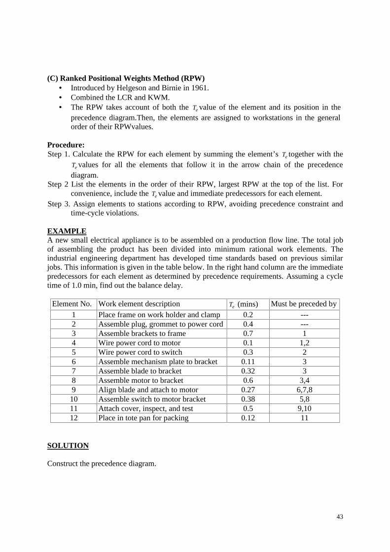
1.9 AUTOMATION PRINCIPLES AND STRATEGIESThere are certain fundamental principles and strategies that can be employed to improveproductivity in manufacturing operations. The approaches are (A) the USA Principle, (B) theTen Strategies for Automation and Production Systems, and (C) an Automation MigrationStrategy.
(A) USA PrincipleThe USA Principle is a common sense approach to automation projects. Similar procedureshave been suggested in the manufacturing and automation trade literature, but none has amore captivating title than this one. USA stands for;
1. Understand the existing process2. Simplify the process3. Automate the process.
Understand the Existing Process. The obvious purpose of the first step in the USA approachis to comprehend the current process in all of its details. What arc the inputs? What are theoutputs? What exactly happens to the work unit between input and output? What is thefunction of the process? How does it add value to the product? What are the upstream anddownstream operations in the production sequence, and can they be combined with theprocess under consideration?
Some of the basic charting tools used in methods analysis are useful in this regard, such asthe operation process chart and the flow process chart. Application of these tools to theexisting process provides a model of the process that can be analyzed and searched forweaknesses (and strengths). The number of steps in the process, the number and placement ofinspections, the number of moves and delays experienced by the work unit, and the timespent in storage can be ascertained by these charting techniques Mathematical models of theprocess may also be useful to indicate relationships between input parameters and outputvariables. What are the important output variables? How are these output variables affectedby inputs to the process, such as raw material properties, process settings, operatingparameters, and environmental conditions? This information may be valuable in identifyingwhat output variables need to be measured for feedback purposes and in formulatingalgorithms for automatic process control.
Simplify the Process. Once the existing process is understood, then the search can begin forways to simplify. This often involves a checklist of Questions about the existing process.What is the purpose of this step or this transport? Is this step necessary? Can this step beeliminated? Is the most appropriate technology being used in this step? How can this step besimplified? Are there unnecessary steps in the process that might be eliminated withoutdetracting from function?
22
Automate the Process. Once the process has been reduced to its simplest form, thenautomation can be considered. The possible forms of automation include those listed in theten strategies discussed in the following section. An automation migration strategy might beimplemented for a new product that has not yet proven itself.
(B) Ten Strategies for AutomationIf automation seems a feasible solution to improving productivity, quality, or other measureof performance, then the following ten strategies provide a road map to search for theseimprovements.
1. Specialization of operations: The first strategy involves the use special purposeequipment designed to perform one operation with the greatest possible efficiency. Thisis analogous to the concept of labor specialization, which has been employed to improvelabor productivity. Reduce oT .
2. Combined operations: Production occurs as a sequence of operations. Complex partsmay require dozens, or even hundreds, of processing steps. The strategy of combinedoperations involves reducing the number of distinct production machines on workstationsthrough which the part must be routed. Reduce mn , hT , and noT .
3. Simultaneous operations: A logical extension of the combined operations strategy is toperform at the same time the operations that are combined at one workstation. In effect,two or more processing (or assembly) operations are being performed simultaneously onthe same workpart, thus reducing total processing time. Reduce mn , hT , noT and oT .
4. Integration of operations: Another strategy is to link several workstations into a singleintegrated mechanism using automated work handling devices to transfer parts betweenstations. In effect, this reduces the number of separate machines through which theproduct must be scheduled. With more than one workstation, several parts can beprocessed simultaneously, thereby increasing the overall output of the system. Reduce mn
, hT , and noT .5. Increased flexibility: This strategy attempts to achieve maximum utilization of
equipment for job shop and medium-volume situations by using the same equipment fora variety of products. This normally translates into lower manufacturing lead time andlower work-in-process. Reduce suT , MLT, WIP; increase U.
6. Improved material handling and storage: A great opportunity for reducingnonproductive time exists in the use of automated material handling and storage systems.Reduce noT , MLT and WIP.
7. On-line inspection: Inspection for quality of work is traditionally performed after theprocess. This means that any poor-quality product has already been produced by the timeit is inspected. Incorporating inspection into the manufacturing process permitscorrections to the process as product is being made. This reduces scrap and brings theoverall quality of product closer to the nominal specifications intended by the designer.Reduce noT and q.
8. Process control and optimization: This includes a wide range of control schemesintended to operate the individual processes and associated equipment more efficiently.By this strategy, the individual process times can be reduced and product qualityimproved. Reduce oT and q.
9. Plant operations control: Whereas the previous strategy was concerned with the controlof the individual manufacturing process, this strategy is concerned with control at theplant level. It attempts to manage and coordinate the aggregate operations in the plant
23
more efficiently. Its implementation usually involves a high level of computernetworking within the factory. Reduce noT , MLT and increase U.
10. Computer integrated manufacturing (CIM: Taking the previous strategy one stepfurther, we have the integration of factory operations with engineering design and manyof the other business functions of the firm. CIM involves extensive use of computerapplications, computer databases, and computer networking in the company. ReduceMLT, design time, production planning time and increase U.
(C) Automation Migration StrategyOwing to competitive pressures in the marketplace, a company often needs to introduce anew product in the shortest possible time. As mentioned previously, the easiest and leastexpensive way to accomplish this objective is to design a manual production method, using asequence of workstations operating independently. The tooling for a manual method can befabricated quickly and allow cost. If more than a single set of workstations is required tomake the product in sufficient quantity, then the manual cell is replicated as many times tomeet demand. If the product turns out to be successful and high future demand is anticipated,then it makes sense for the company to automate production. The improvements are oftencarried out in phases. Many companies have an automation migration strategy: that is, aformalized plan for evolving the manufacturing system, used to produce new products asdemand grows. A typical automation migration strategy is the following
Phase 1: Manual production using single-station manned cells operating independently. Thisis used for introduction of the new product for reasons already mentioned: quick and low-costtooling to get started.
Phase 2· Automated production using single-station automated cells operating independently.As demand for the product grows, and it becomes clear that automation can be justified, thenthe single stations are automated to reduce labor and increase production rate. Work units arestill moved between workstations manually.
Phase 3: Automated integrated production using a multi-station automated system with serialoperations and automated transfer of work units between stations. When the company iscertain that the product will be produced in mass quantities and for several years, thenintegration of the single-station automated cells is warranted to further reduce labor andincrease production rate.
Details of the automation migration strategy vary from company to company, depending onthe types of products they make and the manufacturing processes they perform. But wellmanaged manufacturing companies have policies like the automation migration strategy.Advantages of such a strategy include:
It allows introduction of the new product in the shortest possible time, sinceproduction cells based on manual workstations are the easiest to design andimplement.
It allows automation to be introduced gradually (in planned phases), as demand forthe product grows, engineering changes in the product are made, and time is allowedto do a thorough design job on the automated manufacturing system.
It avoids the commitment to a high level of automation from the start, since there isalways a risk that demand for the product will not justify it.
24
1.10 COSTS IN MANUFACTURINGDecisions on automation and production systems are usually based on the relative costs ofalternatives. Manufacturing costs can be classified into two major categories: (1) fixed costsand (2) variable costs.
A fixed cost is one that remains constant for any level of production output which includesthe cost of the factory building and production equipment, insurance, and property taxes. Allof the fixed costs can be expressed as annual amounts. Expenses such as insurance andproperty taxes occur naturally as annual costs. Capital investments such as building andequipment can be converted to their equivalent uniform annual costs using interest ratefactors.
A variable cost is one that varies in proportion to the level of production output. As theoutput increases, variable cost increases. Examples include direct labor, raw materials, andelectric power to operate the production equipment. The ideal concept of variable cost is thatit is directly proportional to output level. When fixed cost and variable cost are added, wehave the following total cost equation:
TC == FC + VC (Q)
Figure 1.7 Fixed and variable costs as a function of production output for manual andautomated production methods.
where TC = total annual cost (Rs./yr), FC = fixed annual cost (Rs./yr), VC = variable cost(Rs./pc), and Q = annual quantity produced (pc/yr).
When comparing automated and manual production methods, it is typical that the fixed costof the automated method is high relative to the manual method, and the variable cost ofautomation is low relative to the manual method, as pictured in Figure 1.7. Consequently, themanual method has a cost advantage in the low quantity range, while automation has anadvantage for high quantities.
Direct labor, Material, and Overhead
25
Fixed versus variable are not the only possible classifications of costs in manufacturing. Analternative classification separates costs into: (1) direct labor, (2) material, and (3) overhead.This is often a more convenient way to analyze costs in production. The direct labor cost isthe sum of the wages and benefits paid to the workers who operate the production equipmentand perform the processing and assembly tasks. The material cost is the cost of all rawmaterials used to make the product. In the case of a stamping plant, the raw material consistsof the steel sheet stock used to make stampings. For the rolling mill that made the sheet stock,the raw material is the iron ore or scrap iron out of which the sheet is rolled. In the case of anassembled product, materials include component parts manufactured by supplier firms. Thusthe definition of "raw material" depends on the company. The final product of one companycan be the raw material for another company. In terms of fixed and variable costs, direct laborand material must be considered as variable costs.
Overhead costs are all of the other expenses associated with running the manufacturing firm.Overhead divides into two categories: (I) factory overhead and (2) corporate overhead.Factory overhead consists of the costs of operating the factory other than direct labor andmaterials. Factory overhead is treated as fixed cost, although some of the items in our listcould be correlated with the output level of the plant. Corporate overhead is the cost ofrunning the company other than its manufacturing activities. A list of typical factory andcorporate overhead expenses is presented in Table 1. Many companies operate more than onefactory, and this is one of the reasons for dividing overhead into factory and corporatecategories. Different factories may have significantly different factory overhead expenses.
Table 1 Factory and Corporate Overhead expenses
Factory Overhead Corporate OverheadPlant supervisionLine foremanMaintenance crewCustodial servicesSecurity personnelTool crib attendantMaterial handlingShipping and receivingApplicable taxesInsuranceHeat and air conditioningLightPower for machineryFactory depreciationEquipment depreciationFringe benefits
Corporate executivesSales and marketingAccounting departmentFinance departmentLegal counselEngineeringResearch and developmentOther support personnelApplicable taxesCost of office spaceSecurity personnelHeat and air conditioningLightInsuranceFringe benefitsOther office costs
26
1.11 AUTOMATED FLOW LINES
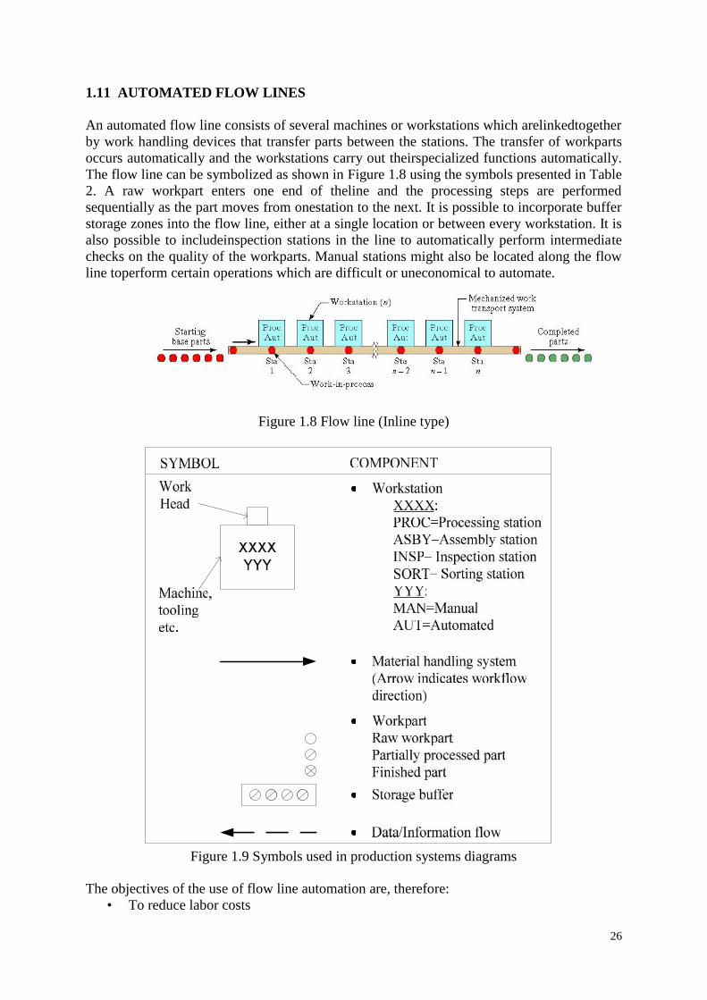
An automated flow line consists of several machines or workstations which arelinkedtogetherby work handling devices that transfer parts between the stations. The transfer of workpartsoccurs automatically and the workstations carry out theirspecialized functions automatically.The flow line can be symbolized as shown in Figure 1.8 using the symbols presented in Table2. A raw workpart enters one end of theline and the processing steps are performedsequentially as the part moves from onestation to the next. It is possible to incorporate bufferstorage zones into the flow line, either at a single location or between every workstation. It isalso possible to includeinspection stations in the line to automatically perform intermediatechecks on the quality of the workparts. Manual stations might also be located along the flowline toperform certain operations which are difficult or uneconomical to automate.
Figure 1.8 Flow line (Inline type)
Figure 1.9 Symbols used in production systems diagrams
The objectives of the use of flow line automation are, therefore:• To reduce labor costs
27
• To increase production rates• To reduce work-in-process• To minimize distances moved between operations• To achieve specialization of operations• To achieve integration of operations
1.11.1 Configurations of automated flow line.
(1) In-line type: The in-line configuration consists of a sequence of workstations in amoreorless straight line arrangement as shown in Figure 1.8. An example of an in-linetransfermachine used for metalcutting operations is illustrated in Figure 1.10 and 1.11.
Figure 1.10 Example of 20 stations In-line
Figure 1.11 Example of 20 stations In-line configuration
28
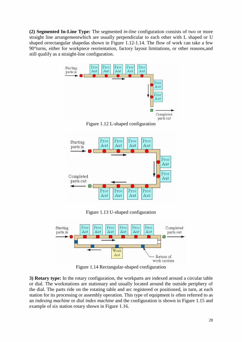
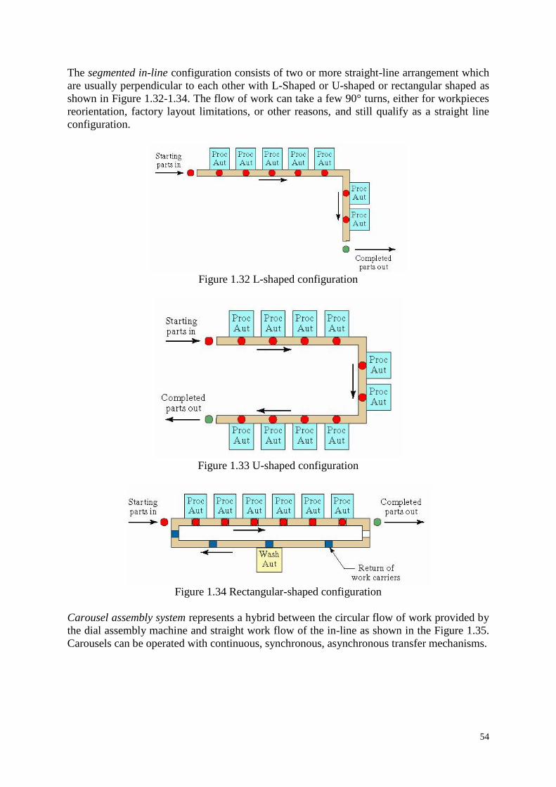
(2) Segmented In-Line Type: The segmented in-line configuration consists of two or morestraight line arrangementwhich are usually perpendicular to each other with L shaped or Ushaped orrectangular shapedas shown in Figure 1.12-1.14. The flow of work can take a few90°turns, either for workpiece reorientation, factory layout limitations, or other reasons,andstill qualify as a straight-line configuration.
Figure 1.12 L-shaped configuration
Figure 1.13 U-shaped configuration
Figure 1.14 Rectangular-shaped configuration
3) Rotary type: In the rotary configuration, the workparts are indexed around a circular tableor dial. The workstations are stationary and usually located around the outside periphery ofthe dial. The parts ride on the rotating table and arc registered or positioned, in turn, at eachstation for its processing or assembly operation. This type of equipment is often referred to asan indexing machine or dial index machine and the configuration is shown in Figure 1.15 andexample of six station rotary shown in Figure 1.16.
29
Figure 1.15 Rotary configuration
Figure 1.16 Example of 6 station rotary configuration
1.11.2 Methods of workpart transport
The transfer mechanism of the automated flow line must not only move the partiallycompleted workparts or assemblies between adjacent stations, it must also orient and locatethe parts in the correct position for processing at each station. The general methods oftransporting workpieces on flow lines can be classified into the following three categories:
1. Continuous transfer2. Intermittent or synchronous transfer3. Asynchronous or power-and-free transfer
The most appropriate type of transport system for a given application depends on such factorsas:
• The types of operation to be performed• The number of stations on the line• The weight and size of the work parts• Whether manual stations are included on the line• Production rate requirements• Balancing the various process times on the line
30
(1) Continuous transfer: With the continuous method of transfer, the workparts are movedcontinuously at constant speed. This requires the workheads to move during processing inorder tomaintain continuous registration with the workpart. For some types of operations,thismovement of the workheads during processing is not feasible. It would bedifficult, forexample, to use this type of system on a machining transfer linebecause of inertia problemsdue to the size and weight of the workheads. In othercases, continuous transfer would be verypractical. Examples of its use are in beverage bottling operations, packaging, manualassembly operations where thehuman operator can move with the moving flow line, andrelatively simpleautomatic assembly tasks. In some bottling operations, for instance, thebottles aretransported around a continuously rotating drum. Beverage is discharged intothemoving bottles by spouts located at the drum's periphery. The advantage of thisapplicationis that the liquid beverage is kept moving at a steady speed and hencethere are no inertiaproblems.
Continuous transfer systems are relatively easy to design and fabricate and canachieve a highrate of production.
(2) Intermittent transfer: As the name suggests, in this method the workpieces aretransported with an intermittent or discontinuous motion. The workstations are fixed inposition and theparts are moved between stations and then registered at the proper locationsforprocessing. All workparts are transported at the same time and, for this reason, theterm"synchronous transfer system" is also used to describe this method ofworkpart transport.
(3) Asynchronous transfer: This system of transfer, also referred to as a "power-and-freesystem," allows each workpart to move to the next station when processing at the currentstation has beencompleted. Each part moves independently of other parts. Hence, some partsare beingprocessed on the line at the same time that others are being transported betweenstations.
Asynchronous transfer systems offer the opportunity for greater flexibility than do theothertwo systems, and this flexibility can be a great advantage in certain circumstances. In-processstorage of workparts can be incorporated into the asynchronous systemswith relative ease.Power-and-free systems can also compensate for line balancingproblems where there aresignificant differences in process times between stations.Parallel stations or several seriesstations can be used for the longer operations, andsingle stations can be used for the shorteroperations. Therefore, the averageproduction rates can be approximately equalized.Asynchronous lines are often usedwhere there are one or more manually operated stationsand cycle-time variationswould be a problem on either the continuous or synchronoustransport systems. Larger workparts can be handled on the asynchronous systems. Adisadvantage of the power and free systems is that the cycle rates are generally slower thanfor the other types.
1.12 TRANSFER MECHANISMSThere are various types of transfer mechanisms used to move parts between stations. Thesemechanisms can be grouped into two types: those used to provide linear travelfor in-linemachines, and those used to provide rotary motion for dial indexingmachines.
1.12.1 Linear transfer mechanismsThe commonly used linear transfer mechanisms are (a) the walking beam transfer bar system,(2) the powered roller conveyor system, and (3) the chain-drive conveyor system.
31
(a) Walking beam systemsWith the walking beam transfer mechanism, the work-parts are lifted up from theirworkstation locations by a transfer bar and moved one position ahead, to the nextstation. Thetransfer bar then lowers the pans into nests which position them moreaccurately forprocessing. For speed and accuracy, the motion of the beam is most often generatedby arotating camshaft powered by an electric motor or a roller movement in aprofile powered byhydraulic cylinder. Figure 1.17 shows the working of the beam mechanism.
Figure 1.17 Walking beam transfer system, showing various stage during transfer stage
(b) Powered roller conveyor systemThis type of system is used in general stock handling systems as well as in automated flowlines. The conveyor can be used to move pans or pallets possessing flat riding surfaces. Therollers can be powered by either of two mechanisms. The first is a belt drive, in which a flatmoving belt beneath the rollers provides the rotation of the rollers by friction. A chain driveis the second common mechanism used to power the rollers. Powered roller conveyors areversatile transfer systems because they can be used to divert work pallets into workstations oralternate tracks. This is shown in Figure 1.18.
(c) Chain-drive conveyor systemIn chain-drive conveyor system either a chain or a flexible steel belt is used to transport thework carriers. The chain is driven by pulleys in either an "over-and under" configuration, inwhich the pulleys turn about a horizontal axis, or an "around-the-corner" configuration, inwhich the pulleys rotate about a vertical axis. Figure 1.19 shows the chain conveyor transfersystem.
32
Figure 1.18 Powered roller conveyor
Figure 1.19 Chain drive conveyor
This general type of transfer system can be used for continuous, intermittent, or non-synchronous movement of workparts. In the non-synchronous motion, the workparts arepulled by friction or ride on an oil film along a track with the chain or belt providing themovement. It is necessary to provide some sort of final location for the workparts when theyarrive at their respective stations.
1.12.2 Rotary transfer mechanismsThere are several methods used to index a circular table or dial at various equal angularpositions corresponding to workstation locations.(a) Rack and pinionThis mechanism is simple but is not considered especially suited to the high-speed operationoften associated with indexing machines. The device is pictured in Figure 1.20 and uses apiston to drive the rack, which causes the pinion gear and attachedindexing table to rotate, Aclutch or other device is used to provide rotation in the desired direction.
Figure 1.20 Rack and pinion mechanism
33
(b) Ratchet and pawlA ratchet is a device that allows linear or rotary motion in only one direction, whilepreventing motion in the opposite direction. Ratchets consist of a gearwheel and a pivotingspring loaded finger called a pawl that engages the teeth. Either the teeth, or the pawl, areslanted at an angle, so thatwhen the teeth are moving in one direction, the pawl slides up andover each tooth inturn, with the spring forcing it back with a 'click' into the depression beforethe nexttooth. When the teeth are moving in the other direction, the angle of the pawl causesit to catch against a tooth and stop further motion in that direction. This drive mechanism isshown in Figure 1.21.
Figure 1.21 Ratchet and pawl mechanism
(c) Geneva mechanismThe two previous mechanisms convert a linear motion into a rotational motion. The Genevamechanism uses a continuously rotating driver to index the table, as pictured in Figure 1.22.If the driven member has six slots for a six-station dial indexing machine, each turn of thedriver will cause the table to advance one-sixth of a turn. The driver only causes movementof the table through a portion of its rotation. For a six-slotted driven member, 120° of acomplete rotation of the driver is used to index the table. The other 240° is dwell. For a four-slotted driven member, the ratio would be 90° for index and 270° for dwell. The usualnumber of indexing per revolution of the table is four, five, six, and eight.
Figure 1.22 Geneva mechanism
34
(d) CAM MechanismsVarious forms of cam mechanism, an example of which is illustrated in Figure 1.23, provideprobably the most accurate and reliable method of indexing the dial. They are in widespreaduse in industry despite the fact that the cost is relatively high compared to alternativemechanisms. The cam can be designed to give a variety of velocity and dwell characteristics.
Figure 1.23 CAM mechanisms
1.13 CONTROL FUNCTIONSControlling an automated flow line is a complex problem, owing to the sheer number ofsequential steps that must be carried out. There are three main functionsthat are utilized tocontrol the operation of an automatic transfer system. The first ofthese is an operationalrequirement, the second is a safety requirement, and the thirdis dedicated to improvingquality.
1. Sequence control:The purpose of this function is to coordinate the sequence of actions ofthe transfer system and its workstations. The various activities of the automated flowlinemust be carried out with split-second timing and accuracy.Sequence control is basic to theoperation of the flow line.
2. Safety monitoring: This function ensures that the transfer system does not operate in anunsafe or hazardous condition. Sensing devices may be added to make certain that the cuttingtool status is satisfactory to continue to process the workpart in the case of amachining-typetransfer line. Other checks might include monitoring certain criticalsteps in the sequencecontrol function to make sure that these steps have all beenperformed and in the correct order.Hydraulic or air pressures might also be checkedif these are crucial to the operation ofautomated flow lines.
3. Quality monitoring: The third control function is to monitor certain quality attributes ofthe workpart. Its purpose is to identify and possibly reject defective workparts andassemblies. Theinspection devices required to perform quality monitoring are sometimesincorporatedinto existing processing stations. In other cases, separate stations are included intheline for the sole purpose of inspecting the workpart.
4. Alternative control strategies:Conventional thinking on the control of the line has been tostop operation when amalfunction occurred. While there are certain malfunctionsrepresenting unsafe conditionsthat demand shutdown of the line, there are other situationswhere stoppageof the line is not required and perhaps not even desirable. There arealternative controlstrategies 1.Instantaneous control and 2. Memory control.
35
(1) Instantaneous control:This mode of control stops the operation of the flow lineimmediately when a malfunction is detected. It is relatively simple, inexpensive, and troublefree. Diagnostic features are often added to the system to aid in identifying the locationandcause of the trouble to the operator so that repairs can be quickly made.However, stoppingthe machine results in loss of production from the entire line,and this is the system's biggestdrawback.
(2) Memory control:In contrast to instantaneous control, the memory system is designed tokeep the machine operating. It works to control quality and/or protect the machinebypreventing subsequent stations from processing the particular workpart and by segregatingthe part as defective at the end of the line. The premise upon whichmemory-type control isbased is that the failures which occur at the stations will berandom and infrequent. If,however, the station failures result from cause and tend torepeat, the memory system will notimprove production but, rather, degrade it. Theflow line will continue to operate, with theconsequence that bad parts will continueto be produced. For this reason, a counter issometimes used so that if a failure occursat the same station for two or three consecutivecycles, the memory logic will cause themachine to stop for repairs.
1.14 BUFFER STORAGEAutomated flow lines are often equipped with additional features beyond the basic transfermechanisms and workstations. It is not uncommon for production flow lines to includestorage zones for collecting banks of workparts along the line. One example of the use ofstorage zones would be two intermittent transfer systems, each without any storage capacity,linked together with a workpart inventory area. It is possible to connect three, four, or evenmore lines in this manner. Another example of workpart storage on flow lines is theasynchronous transfer line. With this system, it is possible to provide a bank of workparts forevery station on the line.
There are two principal reasons for the use of buffer storage zones. The first is to reduce theeffect of individual station breakdowns on the line operation. The continuous or intermittenttransfer system acts as a single integrated machine. When breakdowns occur at the individualstations or when preventive maintenance is applied to the machine, production must behalted. In many cases, the proportion of time the line spends out of operation can besignificant, perhaps reaching 50% or more. Some of the common reasons for line stoppagesare:
Tool failures or tool adjustments at individual processing stations Scheduled tool changes Defective workparts or components at assembly stations, which require that the feed
mechanism be cleared Feed hopper needs to be replenished at an assembly station Limit switch or other electrical malfunction Mechanical failure of transfer system or workstation
When a breakdown occurs on an automated flow line, the purpose of the buffer storage zoneis to allow a portion of the line to continue operating while the remaining portion is stoppedand under repair. For example, assume that a 20-station line is divided into two sections andconnected by a parts storage zone which automatically collects parts from the first sectionand feeds them to the second section. If a station jam were to cause the first section of the lineto stop, the second section could continue to operate as long as the supply of parts in the
36
buffer zone lasts. Similarly, if the second section were to shut down, the first section couldcontinue to operate as long as there is room in the buffer zone to store parts. Hopefully, theaverage production rate on the first section would be about equal to that of the secondsection. By dividing the line and using the storage area, the average production rate would beimproved over the original 20-station Mow line. Figure 1.24 shows the Storage bufferbetween two stages of a production line
Figure 1.24 Storage buffer between two stages of a production
The reasons for using storage buffers are: To reduce effect of station breakdowns To provide a bank of parts to supply the line To provide a place to put the output of the line To allow curing time or other required delay To smooth cycle time variations To store parts between stages with different production rates
The disadvantages of buffer storage on flow lines are increased factory floor space, higher in-process inventory, more material handling equipment, and greater complexity of the overallflow line system. The benefits of buffer storage are often great enough to more thancompensate for these disadvantages.
1.15 AUTOMATION FOR MACHINING OPERATIONS
Transfer systems have been designed to perform a great variety of different metalcuttingprocesses. In fact, it is difficult to think of machining operations that must beexcluded fromthe list. Typical applications include operations such as milling, boring,drilling, reaming, andtapping. However, it is also feasible to carry out operations suchas turning and grinding ontransfer-type systems.
There are various types of mechanized and automated machines that perform a sequence ofoperations simultaneously on different work parts. These include dial indexing machines,trunnion machines, and transfer lines. To consider these machines in approximately the orderof increasing complexity, we begin with one that really doesnot belong in the list at all, thesingle-station machine.
(a) Single-station machineThese mechanized production machines perform several operations on a single workpartwhich is fixtured in one position throughout the cycle. The operations are performedonseveral different surfaces by work heads located around the piece. The availablespacesurrounding a stationary workpiece limits the number of machining headsthat can be used.This limit on the number of operations is the principaldisadvantage of the single-stationmachine. Production rates are usually low tomedium. The single station machine is as shownin Figure 1.25.
37
Figure 1.25 single-station machines(b) Rotary indexing machineTo achieve higher rates of production, the rotary indexing machine performs asequence ofmachining operations on several work parts simultaneously. Parts arefixtured on a horizontalcircular table or dial, and indexed between successivestations. An example of a dial indexingmachine is shown in Figure 1.26.
Figure 1.26 Example of 6 station rotary configuration(c) Trunnion machineTrunnion machine is a vertical drum mounted on a horizontal axis, so it is a variation of thedial indexing machine as shown in Figure 1.27. The vertical drum is called a trunnion.Mounted on it are several fixtures which hold the work partsduring processing. Trunnionmachines are most suitable for small workpieces. The configuration of the machine, with avertical rather than a horizontal indexingdial, provides the opportunity to perform operationson opposite sides of the workpart. Additional stations can be located on the outside peripheryof the trunnion if it is required. The trunnion-type machine is appropriate for workparts in themedium production range.
(d) Center column machineAnother version of the dial indexing arrangement is the center column type, pictured inFigure 1.28. In addition to the radial machining heads located aroundthe periphery of thehorizontal table, vertical units are mounted on the center column of the machine. Thisincreases the number of machining operations thatcan be performed as compared to theregular dial indexing type. The center column machine is considered to be a high-productionmachine which makesefficient use of floor space.
38
Figure 1.27 Six station trunnion machine
Figure 1.28 Ten-station center column machine
39
(e) Transfer machineThe most highly automated and versatile of the machines is the transfer line, asexplainedearlier the workstations are arranged in a straight-line flow pattern andparts are transferredautomatically from station to station (Figure 1.29). The transfer system canbe synchronous orasynchronous, work parts can be transported with or without pallet fixtures, buffer storagecan be incorporated into the line operation if desired, and avariety of different monitoring andcontrol features can be used to manage theline. Hence, the transfer machine offers thegreatest flexibility of any of the machines discussed. The transfer line can accommodatelarger workpieces than the rotary-type indexing systems. Also, the number of stations, andtherefore the number of operations, which can be included on the line is greater than for thecircular arrangement. The transfer line has traditionally been used for machining a singleproduct in high quantities over long production runs. More recently, transfer machines havebeen designed for ease of changeover to allow several different but similar workparts to beproduced on the same line. These attempts to introduce flexibility into transfer line designadd to the appeal of these high-production systems.
Figure 1.29 Example of 20 stations Transfer line
1.16 LINE BALANCINGIn flow line production there are many separate and distinct processing & assemblyoperations to be performed on the product. Invariably, the sequence of processing orassemblysteps is restricted, at least to some extent, in terms of the order in which theoperations can becarried out. For example, a threaded hole must be drilled before it can betapped. Inmechanical fastening, the washer must be placed over the bolt before the nut can be turnedand tightened. These restrictions are called precedence constraints in the languageof linebalancing. It is generally the case that the product must be manufactured at somespecifiedproduction rate in order to satisfy demand for the product. Whether we areconcerned withperforming these processes & assembly operations on automatic machinesor manual flowlines, it is desirable to design the line so as to satisfy all of the foregoingspecifications asefficiently as possible.
The line balancing problem is to arrange the individual processing and assembly tasksat theworkstations so that the total time required at each workstation is approximately thesame. Ifthe work elements can be grouped so that all the station times are exactly equal, wehave
40
perfect balance on the line & we can expect the production to flow smoothly. In mostpracticalsituations it is very difficult to achieve perfect balance. When the workstationstimes areunequal, the slowest station determines the overall production rate of the line.In order toanalyse line balancing problem some terminology and must be discussed.
(a) Minimum Rational Work Element:In order to spread the job to be done on the line among its stations, the job must bedividedinto its component tasks. The minimum rational work elements are the smallestpractical indivisibletasks into which the job can be divided. These work elements cannot besubdivided further. Forexample, the drilling of a hole would normally be considered as aminimum rational work element. Inmanual assembly, when two components are fastenedtogether with a screw & nut, it would bereasonable for these activities to be taken together.Hence, this assembly task would constitute aminimum rational work element. We cansymbolize the time required to carry out this minimum rational work element ejT where j is
used to identify the element out of the nelements that make upthe total work or job.
The time ejT of a work element is considered a constant rather than a variable. An
automaticwork head most closely fits this assumption, although the processing time couldprobably be alteredby making adjustments in the station. In a manual operation, the timerequired to perform a workelement will, in fact, vary from cycle to cycle.
Another assumption implicit in the use of ejT values is that they are additive. The time
toperform two work elements is the sum of the times of the individual elements. In practice,this mightnot be true. It might be that some economy of motion could be achieved bycombining two workelements at one station, thus violating the additivity assumption.
(b) Total Work Content:This is the aggregate of all the work elements to be done on the line. Let wcT be thetimerequired for the total work content. Hence,
1
en
wc ejj
T T
(c) Workstation Process Time:A workstation is a location along the flow line where work is performed, either manually orby some automatic device. The work performed at the station consists of one or more of theindividual work elements and the time required is the sum of the times of the work elementsdone at thestation. We use siT to indicate the process time at station i of an n- station line. Itshould be clear thatthe sum of the station process times should equal the sum of the workelement times.
1 1
cnn
si eji j
T T
(d) Cycle Time:This is the ideal or theoretical cycle time of the flow line, which is the time intervalbetweenparts coming off the line. The design value of cT would be specified according to the
41
requiredproduction rate to be achieved by the flow line. Allowing for downtime on the line,the value of cT must meet the following requirement:
cp
ET
R
Where E is the line efficiency pR the required production rate.
The line efficiency of an automated line will be somewhat less than 100%. For a manual line,where mechanical malfunctions are less likely the efficiency will be closer to 100%.Atefficiencies less than 100%, the ideal cycletime must be reduced (or what is the same thing,the ideal production rate cR must be increased) to compensate for the downtime.
The minimum possible value of cT is established by the bottleneck station, the one with thelargest of sT . That is
maxc siT T
If maxc siT T , there will be idle time at all stations whose sT values are less than cT . Finally,since the station times are comprised of element times,
( 1,2..... )c ej eT T for all j n
This equation states the obvious: that the cycle time must be greater than or equal to anyofthe element times.
(e) Precedence Constraints:These are also referred to as “technological sequencing requirements”. The order in which thework elements can be accomplished is limited at least to some extent. In the problem above,the switch must be mounted onto the motor bracket before the cover of the appliance can beattached.The right hand column in the table above gives a complete listing of the precedenceconstraints for assembling the hypothetical electrical appliance. In nearly every processing orassembly job, there are precedence requirements that restrict the sequence in which the jobcan be accomplished.
In addition to the precedence constraints described above, there may be other typesofconstraints on the line balancing solution. These concern the restrictions on thearrangement of the stations rather than the sequence of work elements. The first is called azoning constraint. A zoning constraint may be either a positive constraint or a negativeconstraint. A positive zoning constraint means that certain work elements should be placednear each other, preferably at the same workstation. For example, all the spray paintingelements should be performed together since a special semi-enclosed workstation has to beutilized. A negative zoning constraint indicates that workelements might interfere with oneanother and should therefore not be located in close proximity. As an illustration, a workelement requiring fine adjustments or delicate coordination should not be located near astation characterized by loud noises and heavy vibrations.
Another constraint on the arrangement of workstations is called a position constraint. Thiswould be encountered in the assembly of large products such as automobiles or majorappliances. The product is too large for one worker to perform work on both sides. Therefore,for the sake of facilitating the work, operators are located on both sides of the flow line. Thistype of situation is referred to as a position constraint.
In the example there are no zoning constraints or position constraints given. The linebalancing methods are not equipped to deal with these constraints conveniently. However, in
42
real-life situations, they may constitute a significant consideration in the design of theflowline.
(f) Precedence Diagram:This is a graphical representation of the sequence of work elements as defined by theprecedence constraints. It is customary to use nodes to symbolize the work elements, witharrows connecting the nodes to indicate the order in which the elements must be performed.Elements that must be done first appear as nodes at the left of the diagram. Then the sequenceof processing and/or assembly progresses to the right. The element times are recorded aboveeach node for convenience.
(g) Balance Delay:Sometimes also called balancing loss, this is a measure of the line inefficiency which resultsfrom idle time due to imperfect allocation of work among stations. It is symbolized as d andcan be computed for the flow line as follows:
c wc
c
nT Td
nT
The balance delay is often expressed as a percent rather than as a decimal fraction. Thebalance delay should not be confused with the proportion downtime, D, of an automated flowline. D is a measure of the inefficiency that results from line stops. The balance delaymeasures the inefficiency from imperfect line balancing.
1.16.1 Methods of Line Balancing (Manual)
(A) Largest candidate rule (LCR)
Procedure:Step 1. List all elements in descending order of eT value, largest eT at the top of the list.Step 2. To assign elements to the first workstation, start at the top of the list and work done,
selecting the firstfeasible element for placement at the station. A feasible element isone that satisfies the precedence requirements and does not cause the sum of the eT
value at station to exceed the cycle time cT .Step 3. Repeat step 2 until no further elements can be added without exceeding cT .
(B) Kilbridge and Wester's Method (KWM) It is a heuristic procedure which selects work elements for assignment to stations
according to their position in the precedence diagram. This overcomes one of the difficulties with the largest candidate rule (LCR), with
which elements at the end of the precedence diagram might be the first candidates tobe considered, simply because their values are large.
Procedure:Step 1. Construct the precedence diagram so those nodes representing work elements of
identical precedence are arranged vertically in columns.Step 2. List the elements in order of their columns, column I at the top of the list. If an
element can be locatedin more than one column, list all columns by the element toshow the transferability of the element.
Step 3. Assign elements to workstations, starting with the column I elements. Continue theassignment procedure in order of column number until the cycle time is reached ( cT ).
43
(C) Ranked Positional Weights Method (RPW) Introduced by Helgeson and Birnie in 1961. Combined the LCR and KWM. The RPW takes account of both the eT value of the element and its position in the
precedence diagram.Then, the elements are assigned to workstations in the generalorder of their RPWvalues.
Procedure:Step 1. Calculate the RPW for each element by summing the element’s eT together with the
eT values for all the elements that follow it in the arrow chain of the precedencediagram.
Step 2 List the elements in the order of their RPW, largest RPW at the top of the list. Forconvenience, include the eT value and immediate predecessors for each element.
Step 3. Assign elements to stations according to RPW, avoiding precedence constraint andtime-cycle violations.
EXAMPLEA new small electrical appliance is to be assembled on a production flow line. The total jobof assembling the product has been divided into minimum rational work elements. Theindustrial engineering department has developed time standards based on previous similarjobs. This information is given in the table below. In the right hand column are the immediatepredecessors for each element as determined by precedence requirements. Assuming a cycletime of 1.0 min, find out the balance delay.
Element No. Work element description eT (mins) Must be preceded by1 Place frame on work holder and clamp 0.2 ---2 Assemble plug, grommet to power cord 0.4 ---3 Assemble brackets to frame 0.7 14 Wire power cord to motor 0.1 1,25 Wire power cord to switch 0.3 26 Assemble mechanism plate to bracket 0.11 37 Assemble blade to bracket 0.32 38 Assemble motor to bracket 0.6 3,49 Align blade and attach to motor 0.27 6,7,810 Assemble switch to motor bracket 0.38 5,811 Attach cover, inspect, and test 0.5 9,1012 Place in tote pan for packing 0.12 11
SOLUTION
Construct the precedence diagram.
44
1
2
3
4
5
6
7
8
9
10
11 12
0.2
0.4
0.7
0.1
0.3
0.11
0.32
0.6
0.27
0.5
0.38
0.12
(A) Solution by Largest Candidate Rule
Step 1: Sorting according to the descending order of the element times.
Step 2 & 3: Assigning work elements to workstations according to LCR
Station Work Element eT (min) Station time (min)1 2 0.4
5 0.31 0.24 0.1 1.0
2 3 0.76 0.11 0.81
3 8 0.610 0.38 0.98
4 7 0.329 0.27 0.59
5 11 0.5012 0.12 0.62
Based on the assignment the work flow is as given below.
45
Balance delay c wc
c
nT Td
nT
= 5 1 4
5 1
= 0.2 = 20 %
(B) Kilbridge and Wester’s Method (KWM)
Step 1: Constructing the precedence diagrams in terms of columns.
Step 2: Arranging work elements according to columns.
Work element Column eT (min) Station time (min)1 I 0.22 I 0.4 0.63 II 0.74 II 0.15 II,III 0.3 1.16 III 0.117 III 0.328 III 0.6 1.039 IV 0.2710 IV 0.38 0.6511 V 0.50 0.5012 VI 0.12 0.12
Step 3: Assigning work elements to stations.
46
Station Element eTeT at station
1 1 0.22 0.44 0.15 0.3 1.0
2 3 0.76 0.11 0.81
3 7 0.328 0.6 0.92
4 9 0.2710 0.38 0.65
5 11 0.5012 0.12 0.62
Since five stations are required, the balance delay is again equal to 20%, the same asprovided by LCR. However, note that the work elements which make up the five stations arenot the same as LCR. Also, for stations that do have the same elements, the sequence inwhich the elements are assigned is not necessarily identical.
In general, the KWM will provide a superior line balancing solution when compared with theLCR. However, this is also not always true as demonstrated herein.
(C) Ranked Positional Weight Method (RPW)
Step 1: Sample calculation: For element 1, the elements that follow it in the arrow chain are 3, 4, 6, 7, 8, 9, 10,
11, and 12. The RPW for element 1 would be the sum of the eT for all these elements, plus eT for
element 1.
Step 2: Arranging work elements according to descending RPW.
In the RPW method, the number of stations required is five, but the maximum station processtime is 0.92 minute at number 3. Accordingly the line could be operated at a cycle time of cT
= 0.92 rather than 1.0 minute. Thus,
Balance delay c wc
c
nT Td
nT
= 5 .092 4
5 0.92
= 0.13 = 13 %
Increase the production rate = 1 / 0.92 = 1.075 units/min.
The RPW solution represents a more efficient assignment of work elements to stationthan either of the two preceding solutions. However, this result is according to acycle time different from the specified cycle time of 1 min.
If the problem were reworked with cT = 0.92 minute using LCR or WKM, it might bepossible to duplicate the efficiency provided by RPW method.
1.16.2 Computerized Line Balancing MethodsComputer programs have been developed based on several of the heuristic approaches forline balancing. However, the use of the computer allows a more complete enumeration of thepossible solutions to a line balancing problem than is practical with a manual solutionmethod. Accordingly, the computer line balancing algorithms are normally structured toexplore a wide range of alternative allocations of elements to workstations. The computerassisted methods are:
COMSOALThis acronym stands for Computer Method of Sequencing Operations for Assembly Lines. Itis a method developed at Chrysler Corporation and reported by Arcus in 1966. Although itwas not the first computerized line balancing program to be developed, it seems to haveattracted considerably more attention than those which preceded it. The procedure is to iteratethrough a sequence of alternative solutions and keep the best one. The basic algorithm ofCOMSOAL is;Step 1. Construct list A, showing all work elements in one column and the total number of
elements that immediately precede each element in an adjacent column. This isillustrated in Table 1. Note that these types of data would be quite easy to compileand manipulate by the computer.
48
Step 2. Construct list B (Table 2), showing all elements from list A that have no immediatepredecessors.
Step 3. Select at random one of the elements from list B. The computer would beprogrammed to perform this random selection process. The only constraint is that theelement selected must not cause the cycle time cT to be exceeded.
Step 4. Eliminate the element selected in step 3 from lists A and B and update both lists ifnecessary. Updating may be needed because the selected element was probably animmediate predecessor for some other elements(s). Hence, there may be changes inthe number of immediate predecessors for certain elements in list A; and there maynow be some new elements having no immediate predecessors that should be addedto list B. To illustrate, suppose in step 3 that element 1 is chosen at random for entryinto the first workstation. This would mean that element 3 no longer has anyimmediate predecessors. Tables 3 and 4 show the updated lists A and B, respectively.
Step 5. Again select one of the elements from list B which is feasible for cycle time.Step 6. Repeat steps 4 and 5 until all elements have been allocated to stations within the Tc
constraint. One possible solution to the problem is shown in Table 5. The balancedelay is again d = 20%, the same efficiency as obtained with the largest candidaterule and the Kilbridge and Wester method.
Step 7. Retain the current solution and repeat steps 1 through 6 to attempt to determine animproved solution. If an improved solution is obtained, it should be retained.
Table 1 List A in COMSOAL at the beginning of the Sample Problem
Work Element Number of Immediate predecessor1 02 03 14 25 16 17 18 29 310 211 212 1
Table 2 List B in COMSOAL at the beginning of the Sample Problem
Elements with no immediate predecessor11
49
Table 3 List A in COMSOAL after Step 3
Work Element Number of Immediate predecessor2 03 04 15 16 17 18 29 310 211 212 1
Table 4 List B in COMSOAL after Step 3
Elements with no immediate predecessor23
Table 5 Possible solution with COMSOAL
Station Element eTeT at station
1 1 0.22 0.45 0.34 0.1 1.0
2 3 0.76 0.11 0.81
3 8 0.610 0.38 0.98
4 7 0.329 0.27 0.59
5 11 0.5012 0.12 0.62
The steps involved in the COMSOAL algorithm represent an uncomplicated datamanipulation procedure. It is therefore ideally suited to computer programming with large setof work elements. Although there is much iteration in the algorithm, this is of minorconsequence because of the speed with which the computer is capable of performing theiterations.
CALBIn 1968 the Advanced Manufacturing Methods Program (AMM) of the IIT Research Instituteintroduced a computer package called CALB (for Computer Assembly Line Balancing orComputer-Aided Line Balancing). Its applications have included a variety of assembledproducts, including automobiles and trucks, electronic equipment, appliances, militaryhardware, and others. CALB can be used for both single-model and mixed-model lines. For
50
the single-model case, the data required to use the program include the identification of eachwork element eT for each element, the predecessors, and other constraints that may apply tothe line. Also needed to balance the line is information on minimum and maximum allowabletime per workstation (in other words, cycle time data). The CALB program starts by sortingthe elements according to their Te and precedence requirements. Based on this sort, elementsare assigned to stations so as to satisfy the minimum and maximum allowable station times.To use CALB on mixed model lines, additional data are required such as the productionrequirements per shift for each model to be run on the line, and a definition of relativeelements usage per model.
ALPACAThis computer system was developed by General Motors in 1967. The acronym represents“Assembly Line Planning and Control Activity.” ALPACA is described as an interactive linebalancing system in which the user can transfer work from one station to another along theflow line and immediately assess the relative efficiency of the change. ALPACA wasdesigned to cope with the complications due to product changeover on the assembly line. Thesystem user can quickly determine what changes in work element assignments should bemade to maintain a reasonable line balance for the ever changing product flow.
1.16.3 Other ways to improve the Line Balance1. Dividing work elements: The minimum rational work element is to be judiciously
determined. In some cases although a work element can be further divided, still it canbe taken as minimum rational work element to avoid bottleneck situation.
2. Changing workhead speeds at automatic stations: Through a process increasing thespeed/feed combinations at the stations with long process time, and reducing thespeed/feed combinations at stations with idle time, it should be possible to improvethe balance on the flow line. This would tend to reduce the frequency of downtimeoccurrences on the line.
3. Method analysis The study of human work activity may result in better workplacelayout, redesigned tooling and fixturing or improved hand and body motions.
4. Pre-assembly of components: Reduce the total amount of work done on the regularassembly line by another assembly cell or by outsourcing. The reasons may be (a)required process may be difficult to implement on the regular assembly line, (b)variations in process times (adjustments or fitting) may result in a longer cycle time,and (c) an assembly cell setup in the plant or a vendor with certain specialcapabilities to perform the work may be able to achieve higher quality.
5. Inventory buffers between stations: Storage buffers may be in use to take care of thecycle time variation due to human activity which is characterized by randomvariations.
6. Parallel stations: These may be used to avoid bottleneck situation due to sequentialnature of line.
1.17 FLEXIBLE MANUAL ASSEMBLY LINESThe well defined pace of a manual assembly line has merit from the point of view ofmaximizing production rate. However, the workers on the assembly line often feel as if theyare being driven too hard. Frequent complaints by the workers, poor-quality workmanship,sabotage of the line equipment, and other problems have occurred on high-production flowlines. To relieve some of these conditions, a new concept in assembly lines has developed inwhich the pace of the work is controlled largely by the workers at the individual stationsrather than by a powered conveyor moving at a fixed speed.
51
The new concept was pioneered by Volvo in Sweden. It relies on the use of independentlyoperated work carriers that hold major components and/or sub assemblies of the automobileand deliver them to the manual assembly workstations along the line. The work carriers inthe system are called automated guided vehicles (AGVs), and they are designed to followguide paths in the factory which are routed to the various stations. The independentlyoperating work carriers allow the assembly system to be configured with parallel paths,queues of parts between stations, and other features not typically found on a conventional in-line assembly system. In addition, these manual assembly lines can be designed to be highlyflexible, capable of dealing with variations in product and corresponding variations inassembly cycle times at the different work-stations.
The type of flexible assembly system described here is generally used when there are manydifferent models to be produced, and the variations in the models result in significantdifferences in the work content times involved. The work cycle time at any given stationmight range between 4 and 10 min, depending on model type. Production throughput isdetermined by the number of similar stations in parallel. A provisioning station is often usedbefore the bank of parallel assembly stations to load the work carrier with the componentsthat will be needed. This permits flexibility in the routing of the carriers to the differentstations. Hardware items common to all models are usually stocked at the workstations. Thetypical operation of the system allows for time variations at a given station resulting fromworker skill and effort and from model differences. Instead of the sub assembly movingforward at a fixed rate as in a conventional flow line, the worker takes the time needed toaccomplish the work elements required for the particular model currently being processed.When the work is completed, the work carrier is released by the worker to proceed towardthe next assembly operation.
Benefits of this flexible assembly system compared to the conventional assembly line includegreater worker satisfaction, better-quality product, increased capability to accommodatemodel variations, and greater ability to cope with problems that require more time rather thanstopping the entire production line.
1.18 AUTOMATED ASSEMBLY SYSTEMSAutomated assembly refers to the use of mechanized and automated devices to perform thevarious functions in an assembly line or cell. Automated assembly system performs asequence of automated operations to combine multiple components in to a single entity whichcan be a final product or sub assembly. Automated assembly technology should beconsidered under the following conditions. High product demand Stable product design The assembly consists of no more than a limited number of components. The product is designed for automated assembly.
Automated assembly system involves less investment compared to transfer lines because1. Work part produced are smaller in size compared to transfer lines.2. Assembly operations do not have the large mechanical forces and power
requirement.3. Size is very less compared to transfer lines.
52
The following recommendations and principles can be applied in product design to facilitateautomated assembly
Reduce the amount of assembly required: This principle can be realized duringdesign by combining functions within the same part that were previouslyaccomplished by separate components in the product. The use of plastic molded partsto substitute for sheet metal parts is an example of this principle. A more complexgeometry molded into a plastic part might replace several metal parts. Although theplastic part may seem to be more costly, the savings in assembly time probablyjustify the substitution in many cases.
Use modular design: In automated assembly, increasing the number of separateassembly steps that are done by a single automated system will result in an increasein the downtime of the system. To reduce this effect, it can be suggested that thedesign of the product be modular, with perhaps each module requiring a maximum of12 or 13 parts to be assembled on a single assembly system. Also, the sub assemblyshould be designed around a base part to which other components are added.
Reduce the number of fasteners required: Instead of using separate screws and nuts,and similar fasteners, design the fastening mechanism into the component designusing snap fits and similar features. Also, design the product modules so that severalcomponents are fastened simultaneously rather than each component fastenedseparately.
Reduce the need for multiple components to lie handled at once: The preferredpractice in automated assembly machine design is to separate the operations atdifferent stations rather than to handle and fasten multiple componentssimultaneously at the same workstation. (It should be noted that robotic technology iscausing a rethinking of this practice since robots can be programmed to performmore complex assembly tasks than a single station in a mechanized assemblysystem.)
Limit the required directions of access: This principle simply means that thenumbers of directions in which new components are added to the existingsubassembly should be minimized. If all of the components can be added verticallyfrom above, this is the ideal situation. Obviously, the design of the subassemblymodule determines this.
Require high quality in components: High performance of the automated assemblysystem requires consistently good quality of the components that are added at eachworkstation. Poor-quality components cause jams in the feeding and assemblymechanisms which cause downtime in the automated system.
Implement hopperability: This is a term that is used to identify the ease with which agiven component can be fed and oriented reliably for delivery from the parts hopperto the assembly workhead.
1.18.1 Types of automated assembly systemsBased on the type of work transfer system that is used in the assembly system:
• Continuous transfer system
53
• Synchronous transfer system• Asynchronous transfer system• Stationary base part system
The first three types involve the same methods of workpart transport described in automatedflow line. In the stationary base part system, the base part to which the other components areadded is placed in a fixed location, where it remains during the assembly work.
Based on physical configuration:• Dial-type assembly machine• In-line assembly machine• Carousel assembly system• Single-station assembly machine
The dial-type machine, the base parts are indexed around a circular table or dial. Theworkstations are stationary and usually located around the outside periphery of the dial. Theparts ride on the rotating table and are registered or positioned, in turn, at each station a newcomponent is added to base part. This type of equipment is often referred to as an indexingmachine or dial index machine and the configuration is shown in Figure 1.30.
Figure 1.30 Dial type assembly machine
The in-line configuration assembly system consists of a sequence of workstations in a moreor less straight line arrangement as shown in Figure 1.31. The in-line assembly machineconsists of a series of automatic workstations located along an in-line transfer system. It is theautomated version of the manual assembly line. Continuous, synchronous, or asynchronoustransfer systems can be used with the in-line configuration.
Figure 1.31 In-line type assembly machine
54
The segmented in-line configuration consists of two or more straight-line arrangement whichare usually perpendicular to each other with L-Shaped or U-shaped or rectangular shaped asshown in Figure 1.32-1.34. The flow of work can take a few 90° turns, either for workpiecesreorientation, factory layout limitations, or other reasons, and still qualify as a straight lineconfiguration.
Figure 1.32 L-shaped configuration
Figure 1.33 U-shaped configuration
Figure 1.34 Rectangular-shaped configuration
Carousel assembly system represents a hybrid between the circular flow of work provided bythe dial assembly machine and straight work flow of the in-line as shown in the Figure 1.35.Carousels can be operated with continuous, synchronous, asynchronous transfer mechanisms.
55
Figure 1.35 Carousel assembly system
In the single-station assembly machine, the assembly operations are performed at a singlelocation (stationary base part system) as shown in Figure 1.36. The typical operation involvesthe placement of the base part at the workstation where various components are added to thebase. The components are delivered to the station by feeding mechanisms, and one or moreworkheads perform the various assembly and fastening operations.
Figure 1.36 Single station assembly machine
1.18.2 Part feeding devicesIn each of the configurations described above, a means of delivering the components to theassembly workhead must be designed. The hardware system that delivers components to theworkhead in an automated assembly system typically consists of the following elements asshown in Figure 1.37. Parts delivery to workstations depends upon specific pieces of deliveryequipment, particularly associated with automatic assembly. These pieces of equipment areconnected together to create the parts delivery system. The hardware for parts deliveryconsists of:
• Hopper: This is the container into which the components are loaded at theworkstation. A separate hopper is used for each component type. The components areusually loaded into the hopper in bulk. This means that the parts are randomlyoriented initially in the hopper.
• Parts feeder: This is a mechanism that removes the components from the hopperone at a time for delivery to the assembly workhead. The hopper and parts feeder areoften combined into one operating mechanism. The vibratory bowl feeder, picturedin Figure 1.38, is a very common example of the hopper-feeder combination.
56
Figure 1.37 Elements of part delivery system
Figure 1.38 Vibratory bowl feeder
• Selector and/or orientor: These elements of the delivery system establish the properorientation of the components for the assembly workhead. A selector is a device thatacts as a filter, permitting only parts that are in the correct orientation to passthrough. Components that are not properly oriented are rejected back into the hopper.An orientor is a device that allows properly oriented pans to pass through butprovides a reorientation of components that are not properly oriented initially.Several selector and orientor schemes are illustrated in Figure 1.39. Selector andorientor devices are often combined and incorporated into one hopper-feeder system.
• Feed track: The preceding elements of the delivery system are usually located somedistance from the assembly workhead. A feed track is used to transfer thecomponents from the hopper and parts feeder to the location of the assemblyworkhead, maintaining proper orientation of the parts during the transfer. There aretwo general categories of feed tracks: gravity and powered. The gravity feed track ismost common. In this type the hopper and parts feeder are located at an elevation thatis above the elevation of the workhead. The force of gravity is used to deliver thecomponents to the workhead. The powered feed track uses vibratory action, air
57
pressure, or other means to force the parts to travel along the feed track toward theassembly workhead.
Figure 1.39 (a) Selector and (b) orientor devices used upon the feed track
• Escapement and placement device: The purpose of the escapement device is toremove components from the feed track at time intervals that are consistent with thecycle time of the assembly workhead. The placement device physically places thecomponent in the correct location at the workstation for the assembly operation bythe workhead. Several types of escapement and placement devices are shown inFigure 1.40.
Horizontal placement device: Device used on dial-type assembly machines: partsmove via horizontal delivery into vacant nests on the dial, as they appear, fromthe feed track; meanwhile the circular motion of the dial table means that thenests are revolved away from the feed track, permitting the next component in thefeed track to move into the next vacant nest, and so forth.
Vertical placement device: Device used on dial-type assembly machines: here,the parts feeder is arranged vertically above the dial table, so that when the tableturns, to reveal an empty nest, the component can fall by gravity from the feedtrack into the empty nest. Successive parts fall by gravity to take up their positionat the mouth of the feed track in turn.
Escapement device: This device is actuated by the top of the carrier contactingthe lower surface of the rivet-shaped part, causing its upper surface to pressagainst the spring blade, which releases the part so that it falls into the workcarrier nest. The work carriers are moved horizontally to cause the release of thepart. After the first part has escaped the work carrier released part moves off andto be replaced by the next work carrier, and so forth.
Pick-and-place mechanism: This mechanism uses a pick-and-place unit with arevolving arm, so that parts may be removed from the feed track, and placed intowork carriers.
MODULE-II2.0 OVERVIEW OF CADComputer aided design (CAD) can be defined as the use of computer systems to assist in thecreation, modification, analysis or optimization of a design.The computer systems consist ofthe hardware and software to perform the specialized design functions required by the user.Modern CAD systems are based on interactive computer graphics (ICG). Interactivecomputer graphics denotes a user-oriented system in which the computer is employed tocreate, transform and display data in the form of pictures or symbols.
The hardware of the ICG system includes a central processing unit, one or more workstations(including the graphics display terminals) and peripheral devices such as printers, plottersand drafting equipment. The software consists of the computer programs needed toimplement graphics processing on the system. The software would also typically includeadditional specialized application programs to accomplish a particular engineering functionsrequired by the user. The ICG system is one component of a computer aided design system.The other major ICG component is the human designer. Interactive computer graphics is atool used by the designer to solve a design problem, In effect, the ICG system magnifies thepowers of the designer. This has been referred to as the synergistic effect. The designerperforms the portion of the design process that is most suitable to human intellectual skills,the computer performs the task best suited to its capabilities and the resulting system exceedsthe sum of its components.
2.1 REASONS FOR IMPLEMENTING CAD1. To increase the productivity of the designer: CAD helps the designer to visualize the
product and its component sub-assemblies and parts. This reduces the time requiredto synthesize, analyze and document the design. This productivity improvementresults not only into lower design cost but also into shorter design project completiontimes.
2. To improve the quality of design: A CAD system permits a thorough engineeringanalysis within a short time using various software and a larger number of designalternatives can be investigated. Design errors are also reduced by the accuracy builtinto the system by means of calculations and checks available with the system. Thesefactors lead to improvement in the quality and accuracy in the design.
3. To improve communications through documentation: The use of CAD systemprovides better engineering drawings, more standardization in the drawings, betterdocumentation of the design, fewer drawing errors and greater legibility for thedrawing.
4. To create adatabase for manufacturing: to the process of creating the documentationfor the product design (geometry and dimension of components, bill of materials,etc.) much of the required database to manufacture is also created which can beapplied for several computer integrated manufacturing (CIM) applications like CNCprogramming, programming of robots, process planning and so on.
2.2 THE DESIGN PROCESSDesign is the act of devising an original solution to a problem by a combination of principles,resources and products in design. Design process is the pattern of activities that is followedby the designer in arriving at the solution of a technological problem. A preliminary design ismade based on the available information and is improved upon as more and moreinformation is generated. The process of design is segmented into six stages as shown inFigure 2.1. The design process is repetitive as well as creative. The repetitive tasks can be
60
performed by computers; however, the creative tasks (stages 1 and 2) are always done onlyon the efforts of human being.
Figure 2.1 CAD modified design process
Stage 1 : Recognition of need. Recognizing the fact that there is a need for a new productfor intended function. It may also include the modification in the existing product.
Stage 2 : Problem definition. Problem is fully defined in terms of functionality and meetingother requirements such as ergonomic; performance-data, statutory, etc. Thus fullspecifications of product can be yielded. [Crude representation of idea.]
Stage 3 : Synthesis. The design undergoes synthesis, joining its various elements.Stage4 : Analysis and optimization. Product analysis reveals the weaknesses and thus
weaknesses can be considered for improvement. This process is repeated until anacceptable design achieved.
Stage 5 : Evaluation. The optimized design is reviewed from the point of view of expectedperformance. It can be done through prototype modeling and against the setstandard.
Stage6 : Presentation. Stages 4 and 5 are repeated until acceptable, optimized design isachieved. These stages are basically iterative in nature. Iteration depends on thecreativeness, ingenuity (skill for devising) and experience of designers and thesoftware (tools) available. The process (stage 1 and 2) are human dependent whilethe stages 3, 4, 5 and 6 (four stages) are computer based (CAD).
61
Application of computers in designEngineering design has traditionally been accomplished on drawing boards with the designbeing documented in the form of a detailed engineering drawing. This process is iterative innature and is time consuming. The computer can beneficially be used in the design process inCAD. The design task is performed by a CAD system rather than a single designer workingover a drawing board. The various design related tasks, which are performed by the CADsystem, can be grouped into four functional areas (Figure 2.1):
1. Geometric ModelingGeometric modeling is concerned with the computer compatible mathematical description ofthe geometry of an object. The mathematical description allows the image of the object to bedisplayed and manipulated on a graphics terminal through signals from the CPU of the CADsystem. The software that provides geometric modeling capabilities must be designed forefficient use both by the computer and the human designer.
There are different methods of representing the object in geometric modeling. The basic formuses wire frames to represent the object. In this form, the object is displayed byinterconnected lines. Geometric modeling is classified into three types.a. 2D : Two-dimensional representation is used for a flat object.b. 2½ D : This goes somewhat beyond the 2D capability by permitting a three-
dimensional object to be represented as long as it has no side-wall details.c. 3D : This allows for full three-dimensional modeling of a more complex
geometry.
Geometric models in CAD can also be classified as wire-frame models, or solid models.Wire-frame models use inter-connecting lines to depict the object drawn; these inter-connecting lines can sometimes be confusing when used on complex part geometries, asmultiple overlapping lines may occur. Solid models are objects that have been modelled insolid three dimensions, providing the user with a vision of the object that is similar to itsappearance in reality This method typically uses solid geometry shapes called primitives toconstruct the object.
2. Engineering AnalysisOnce a design has been developed, it must then be subjected to engineering analysis. Thisanalysis may include various tests, depending on the product, but may include: stress-straincalculations, heat transfer analysis, or dynamic simulation. These analyses tend to be quitecomplex, which has led to the development of computer-aided engineering (CAE) softwarepackages, so that complicated engineering analysis may be performed by computer. FEM anddynamic analysis software packages are generally used for this purpose. The engineeringanalysis includes:
Mass properties analysis- involving the computation of features on the solid model,such as volume, surface area, weight, and centre of gravity;
Tolerance analysis- this determines how product tolerances would affect productfunction and performance, how easy it would be to assemble the product, and howvariations in component dimensions may affect the overall size of the assembly;
62
Finite element analysis- this aids in stress-strain, heat transfer, fluid flow, and otherengineering calculations;
Kinematic and dynamic analysis- this studies the operation of mechanical linkagesand analyzes their motions; and
Discrete event simulation- this models complex operational systems where eventsoccur at discrete moments in time and affect the status and performance of thesystem.
3. Design Review and EvaluationFollowing comprehensive engineering analysis, the proposed design must be evaluated andreviewed for consistency. Some CAD features that are helpful in evaluating and reviewing aproposed design include:
Automatic dimensioning- upon model completion, the CAD software canautomatically generate the dimensions of the drawn model;
Error checking- this checks the accuracy and consistency of dimensions andtolerances, to assess whether the proper design documentation format has beenfollowed;
Animation of discrete-event simulation solutions- this displays the result as a discreteevent simulation, where input parameters, probability distributions, and other factorscan be changed to assess their effect on the performance of the system beingmodelled; and
Plant layout design scores- this provides numerical scores for plant layout designs,based upon such factors as material flow, and closeness ratings.
In many cases, the geometric model is now used to replace the physical prototype that wouldtraditionally be built at this stage. Physical prototypes are usually time-consuming to create,and analyse; and so replacements in the form of rapid prototyping, and virtual prototyping-both based upon the geometric model, may be used instead.
Rapid prototyping is a term applied to a family of fabrication technologies that allowengineering prototypes of solid parts to be made in a minimum lead time, based upon theCAD geometric model. This is done by dividing the solid object into layers, and thendefining the area of each layer. The rapid prototyping process then fabricates the object bystarting at the base layer, and building towards the top layer. The fidelity of theapproximation that is produced by this method is dependent on the layer thickness used at thestart (with greater accuracy achieved with thinner layers used).
Virtual prototyping is based upon virtual reality technology, and uses the CAD geometricmodel to construct a digital mock-up of the product. This mock-up allows the designer toobtain the sensation of the real physical product, without actually building the physicalprototype.
Rapid prototyping creates a physical prototype by means of segmenting the CAD geometricmodel into a series of layers, and building to that specification; while virtual prototyping usesthe CAD geometric model to construct a digital mock-up of the product.
A procedure called layering is often helpful in design review. For example, a goodapplicationof layering involves over-layering the geometric image of the final shape of themachined part on top of the image of the rough casting. This ensures that sufficient material
63
is available on the casting to accomplish the final machined dimensions. This procedure canbe performed in stages to check each successive step till the processing of the part,
Another related procedure for design review is interference checking. This involves theanalysis of an assembled structure in which the risk that the components of the assembly mayoccupy the same space. This risk occurs in the design of large chemical plants, air-separationcold boxes and other complicated piping structure.
One of the most interesting evaluation features available on some CAD system is kinematics;the available kinematics packages provide the capability to animate the motion of simpledesigned mechanisms such as hinged components and linkages. This capability enhances thedesigner’s visualization of the operation of the mechanism and helps to ensure againstinterference with other components without graphical kinematics on a CAD system.
4. Automated DraftingAutomated drafting involves the creation of hardcopy engineering drawings directly from theCAD database. In some early computer aided design departments, automation of the draftingrepresented the principal justification for investing in the CAD system. Indeed, CAD systemscan increase productivity in the drafting function by roughly five times over manual drafting.Some of the graphics features of computer aided design systems lend themselves especiallywell to the drafting process. These features include automatic dimensioning generation ofcrosshatched areas, seating of the drawing and capability to develop sectional views andenlarged views of particular part details, the ability to rotate the part or to perform othertransformations of the image (e.g., oblique isometric or perspective views).
2.3 CREATING MANUFACTURING DATA BASEThe important reason for using a CAD system is that it offers the opportunity to develop thedatabase needed to manufacture the product. In the conventional manufacturing cycle,engineering drawings were prepared by design draftsmen and then used by manufacturingengineers to develop the process plan (i.e., route sheets). The activities involved in designingthe product were separated from the activities associated with process planning. Basically atwo-step procedure was employed. This was both time consuming and involved duplicationof effort by design and manufacturing engineers. In an integrated CAD/CAM system, a directlink is established between product design and manufacturing. It is the goal of CAD/CAMnot only to automate certain phases of design and certain phases of manufacturing but also toautomate the transition from design to manufacturing. Computer based systems have beendeveloped which create much of the data and documentation required to plan and manage themanufacturing operations for the product.
The manufacturing database is an integrated CAD/CAM database. It includes all the data onthe product generated during design, i.e., geometry data, bill of material and assembly lists,material specifications, etc. as well as additional data required for manufacturing, much ofwhich is based on the product design. Figure 2.2 shows how the CAD/CAM database isrelated to design and manufacturing.
64
Figure 2.2 Relationship of CAD/CAM database to CAD and CAM
2.4 BENEFITS OF CADThere are many benefits of computer aided design, only some of which call be easilymeasured. Some of the benefits are intangible which are reflected in improved work qualityand more pertinent and usable information. Some of the benefits are tangible which arediscussed hereinafter.1. Productivity improvement in design: CAD helps in increased design productivity by
reducing the time for developing conceptual design, analysis and drafting. It is alsopossible to reduce the manpower requirements for a given project. Productivityimprovement in computer aided design process is dependent on factors such as;
Complexity of the drawingDegree of repetitiveness of features in the designed partsDegree of symmetry in the partsExtensive use of library of user defined shapes and commonly used entities
2. Shorter lead times: Interactive CAD is inherently faster than traditional manual designprocess. CAD tools reduce the number of iterations. It speeds up the task of preparingreports and bill of materials using a CAD system. A finished set of component drawingsand documentation can be prepared in a relatively short time. Shorter lead times in designresult in reduction of the elapsed time between receipt of customer order and delivery ofthe finished product. The enhanced productivity of the designers working in CADenvironment will reduce the importance of design, engineering analysis and drafting ascritical time elements in the overall manufacturing lead time.
3. Design analysis: The design analysis routines available in a CAD system help tooptimize the design into an appropriate logical work pattern. The use of design analysissoftware such as finite element analysis and kinematics analysis reduces the time andimproves the design accuracy. Instead of having feedback sessions between design andanalysis groups, the designer can perform the analysis while working on a CADworkstation. This enhances the concentration of designers, since the process is interactivein nature, Calculation of mass properties can be made almost instantaneously.
4. Fewer design errors: Interactive CAD systems have inherent capability for avoidingerrors in design, drafting and documentation. These errors occur during manual handling.Errors are avoided because interactive CAD systems perform time consuming andrepetitive functions such as multiple symbol placements,
65
5. Flexibility in design: Interactive CAD systems apart from generating designs withrepetitive accuracy offers the advantage of easy modification of design to satisfycustomer's specific requirements.
6. Standardization of design, drafting and documentation: The single database andoperating system used in CAD provide a common basis for design, analysis and draftingprocess with interactive CAD systems, drawings are "standardized" as they are drawn, Itis also possible to reuse previous modules in developing a range of products.
7. Drawings are more understandable: With the increase in the use of 3D views and solidmodelling, it has become easier to comprehend the features of the component readily.One does not have to reconstruct mentally the solid shape from 20 objects. Manysoftware packages allow 3D view generation from a 2D model. This has severaladvantages from the manufacturing pointof view.
8. Improved procedures for engineering changes: Control and implementation ofengineering changes can be significantly improved with computer-aided design. Originaldrawings and reports are stored in the database of the CAD system and are easilyaccessible. Revision information can be retained and new drawings with changes can becreated without destroying previous features.
9. Benefits in manufacturing: The benefits of computer aided design can be used as a basisfor a number of downstream manufacturing operations. Some of the manufacturingbenefitsare:
(a) Tool and fixture design for manufacturing(b) Computer aided process planning(c) Computer aided inspection(d) Preparation of numerical control programs for manufacturing of components
oncomputer numerical control machines(e) Preparation of assembly lists and bill of materials for production(f) Coding and classification of components(g) Production planning and control(h) Assembly sequence planning
2.5 CAD SYSTEM HARDWAREHardware components for computer aided design are available in a variety of sizes,configurations and capabilities. Hence it is possible to select a CAD system that meetstheparticu1ar computational and graphics requirements of the user firm. Engineering firmsthat are not involved in production would choose a system exclusively for drafting and designrelated functions. Manufacturing firms would choose a system to be part of a company-wideCAD/CAM system.
A modem CAD system is based on interactive computer graphics (lCG). However the scopeof CAD includes other computer system as well. For example, computerized design has alsobeen accomplished in a batch mode, rather than in an interactive mode. With interactivegraphics the system provides an immediate response to inputs by the user.The user and thesystem are in direct communication with each other. The user enters commands and respondsto the questions generated by the system. Presently it is restricted to CAD systems whichutilize interactive computer graphics.Typically a stand-alone CAD system would include thefollowing hardware components:
Graphics terminalOperator input devicesCentral processing unit (CPU)
Operator output devicesSecondary storage
These hardware components would be arranged in a configuration as shown in Figure 2.3.
66
Inputdevices
Graphicsterminal
Secondary storagedevice
CPU
Output devices
Design workstation
Figure 2.3 Typical configuration of hardware components in a standalone CAD system
2.5.1 DESIGN WORKSTATIONThe CAD workstation is the system interface with the outside world. It represents animportant factor in determining how convenient and efficient it is for a designer to use theCAD system. The workstation must accomplish five functions:
1. It must interface with the central processing unit.2. It must generate a steady graphic image for the user.3. It must provide digital descriptions of the graphic image.4. It must translate computer commands into operating functions.5. It must facilitate communication between the user and the system.
The use of interactive graphics has been found to be the best approach to accomplish thesefunctions. A typical interactive graphics workstation would consist of the following hardwarecomponents:
Graphics terminalOperator input devices
2.5.2 GRAPHIC TERMINALThere are various different approaches which have been applied to the development ofgraphics terminals. The technology continues to improve their products and reduce theircosts.
(I) Image Generation in Computer GraphicsAll computer graphics terminals which are in use today use the cathode ray tube (CRT) as thedisplay device. Television sets use a form of the same device as the picture tube. Theoperation of the CRT is shown in Figure 2.4. A heated cathode emits a high speed electronbeam onto a phosphor-coated glass screen. The electrons energize the phosphor coatingcausing it to glow at the points where the beam makes contact. By focusing the electronbeam, changing its intensity and controlling its point of contact against the phosphor coatingthrough the use of a deflector system, the beam can be made to generate a picture on the CRTscreen.
There are two basic techniques used in current computer graphics terminals for generating theimage on the CRT screen. They are:
1. Stroke writing2. Raster scan
Other names for the stroke writing technique include line drawing, random position, vectorwriting, and directed beam. Other names for the raster scan technique include digital TV andscan graphics.
67
Figure 2.4 Diagram of cathode ray tube (CRT)
The stroke writing system uses an electron beam which operates like a pencil to create a lineimage on the CRT screen. The image is constructed out of a sequence of straight linesegments. Each line segment is drawn on the screen by directing the beam to move from onepoint on the screen to the next where each point is defined by its x and y coordinates. Theprocess is illustrated in Figure 2.5.
Figure 2.5 Stroke writing for generating images in computer graphics
Although the procedure results in images composed of only straight lines, smooth curves canbe approximated by making the connecting line segments short enough. In the raster scanapproach, the viewing screen is divided i.nto a large number of discrete phosphor pictureelements called pixels. The matrix of pixels constitutes the raster. The number of separatepixels in the raster display might typically range from 256 x 256 to 1024 x 1024 (a total ofover 65,000 points to 1,000,000 points). Each pixel on the screen can be made to glow with adifferent brightness. Colour screens provide for the pixels to have different colours as well asbrightness.
During operation an electron beam creates the image by sweeping along a horizontal line onthe screen from left to right and energizing the pixels in that line during the sweep when thesweep of one line is completed. The electron beam moves to the next line below and proceedsin a fixed pattern as portrayed in Figure 2.6. After sweeping the entire screen the process isrepeated at a rate of 30 to 60 entire scans of the screen per second.
68
Figure 2.6 Raster scan approach for generating images in computer graphics
(II) Graphics TerminalsThe two approaches described earlier are used till the majority of current day CAD graphicsterminals. There are also a variety of other technical factors which result in different types ofgraphics terminals. These factors include the type of phosphor coating on the screen, whetherthe colour is required, the pixel density and the amount of computer memory available togenerate the picture. The three types of graphics terminals are:
(a) Directed Beam Refresh Tube (DBRT)The directed beam refresh terminal utilizes the stroke writing approach to generate the imageon the CRT screen. The term refresh in the name refers to the fact that the image must beregenerated many times per second in order to avoid noticeable flicker of the image. Thephosphor elements on the screen are capable of maintaining their brightness for only a shorttime. In order for the image to be continued, these picture tubes must be refreshed by causingthe directed beam to retrace the image repeatedly on densely filled screens (very detailed lineimages or many characters of text). It is difficult to avoid flickering of the image with thisprocess.
There are several advantages associated with the directed beam refresh systems. Because theimage is being continually refreshed, selective erasure and alteration of the image is readilyaccomplished. It is also possible to provide animation of the image with a refresh rube.
The directed beam refresh system is the oldest of the modern graphics display technologies.Other names sometimes used to identity this system include vector refresh and stroke writingrefresh. Early refresh tubes were very expensive, but the steadily decreasing cost of solidstate circuitry has brought the price of these graphics systems down to a level which iscompetitive with other types.
(b) Direct View Storage Tube (DVST)DVST terminals also use the stroke writing approach to generate the image on the CRTscreen.The term storage tube refers to the ability of the screen to retain the image which hasbeen projected against it, thus avoiding the need to rewrite the image constantly.What makesthis possible is the use of an electron flood gun directed at the phosphor coated screen whichkeeps the phosphor elements illuminated once they have been energized by the stroke writing
69
electron beam. The resulting image on the CRT screen is flicker free. Lines maybe readilyadded to the image without concern over their effect on image density or refresh rates.However, the penalty associated with the storage tube is that individual lines cannot beselectively removed from the image.
Storage tubes have been the low cost terminals and are capable of displaying the largeamounts of data either graphical or textual. Because of these features there are probably morestorage tube terminals in service industry. The principal disadvantage of a storage CRT is thatselective erasure is not possible instead if the user wants to change the picture. The changewill not be manifested on the screen until the entire picture is regenerated. Otherdisadvantages include its lack of colour capability, the inability to use a light pen as a dataentry device and its lack of animation capability.
(c) Raster Scan Terminals (Digital TV)Raster scan terminals operate by causing an electron beam to trace a zigzag pattern across theviewing screen. The operation is similar to that of a commercial television set. Thedifferenceis that a TV set uses analog signals originally generated by a video camera toconstruct the image on the CRT screen, while the raster scan ICG terminal uses digital signalsgenerated by acomputer. For this reason the raster scan terminals used in computer graphicsare sometimes called digital TVs.
The introduction of the raster scan graphics terminal using a refresh tube had been limited bythe cost of computer memory. For example, the simplest and lowest cost terminal in thiscategory uses only two beam intensity levels: ON or OFF. This means that each pixel in theviewing screen is either illuminated or dark. A picture tube with 256 lines of resolution and256 addressable points per line to form the image would require 256 x 256 or over 65,000bits of storage. Each bit of memory contains the ON/OFF status of the corresponding pixel onthe CRT screen. This memory is called the frame buffer or refresh buffer.
The picture quality can be improved in two ways by increasing the pixel density or adding agray scale (or colour). Increasing pixel density for the same size screen means adding morelines of resolution and more addressable points per line. A 1024 x 1024 raster screen wouldrequire more than 1 million bits of storage in the frame buffer. A gray scale is accomplishedby expanding the number of intensity levels, which can be displayed on each pixel to storethe intensity level. Two bits are required for four levels, three bits for eight levels and so on.Five or six bits would be needed to achieve an approximation of a continuous gray scale. Fora colour display three times as many bits are required to get various intensity levels for eachof the three primary colours-red, blue and green. A raster scan graphics terminal with highresolution and gray scale can require a very large capacity refresh buffer. Until recentdevelopments in memory technology, the cost of this storage capacity was prohibitive for aterminal with good picture quality.
The capability to achieve colour and animation was not possible except for very lowresolution levels. It is now possible to manufacture digital TV systems for interactivecomputer graphics at prices, which are competitive with the other two types. The advantagesof the present raster scan terminals include the feasibility to use low cost TV monitors, colourcapability and the capability for animation of the image. Many of the importantcharacteristics of the three types of graphics terminals are summarized in Table 2.1.
70
Table 2.1 Comparison of Graphics Terminal FeaturesDBRT DVST Digital TV
1 Image generation Stroke writing Stroke writing Raster scan2 Picture quality Excellent Excellent Moderate to Good3 Data content Limited High High4 Selective erase Yes No Yes5 Gray scale Yes No Yes6 Colour capability Moderate No Yes7 Animation capability Yes No Moderate
2.5.3 OPERATOR INPUT DEVICESGraphics input devices are provided at the graphics workstation to facilitate convenientcommunication between the user and the system. Workstations generally have several typesof input devices to allow the operator to select the various pre-programmed input functions.These functions permit the operator to create or modify an image on the CRT screen or toenter alphanumeric data into the system. This results in a complete part on the CRT screen aswell as a complete geometric description of the part in the CAD database.
Different CAD system vendors offer different types of (graphics) operator input devices.These devices can be divided into three general categories:
(a) Cursor control devices(b) Digitizers(c) Alphanumeric and other keyboard terminals
Cursor control devices and digitizers are both used for graphical interaction with the system.Keyboard terminals are used as input devices for commands and numerical data. There aretwo basic types of graphical interaction accomplished by means of cursor control anddigitizing creating and positioning new items on the CRT screen. Pointing at or otherwiseidentifying locations on the screen, usually associated with existing images ideally, agraphical input device should lend itself to both of these functions. However this is difficultto accomplish with a single unit and that is why most workstations have several differentinput devices.
(a) Cursor Control DevicesThe cursor manually takes the form of a bright spot on the CRT screen that indicates wherelettering or drawing will occur. The computer is capable of reading the current position of thecursor. Hence the user's capability to control the cursor position allows locational data to beentered into the CAD system database. A typical example would be for the user to locate thecursor to identify the starting point of a line. Another, more sophisticated case would be forthe user to position the cursor to select an item from a menu of functions displayed on thescreen.
For instance, the screen might be divided into two sections one of which is an array of blockswhich correspond to operator input functions. The user simply moves the cursor to thedesired block to execute the particular function. There are a variety of cursor control deviceswhich have been employed in CAD systems. These include:
Thumb wheelsDirection keys on a keyboardJoysticksTracker ball
Light penElectronic tablet/penMouse
71
The first four items in the list provide control over the cursor without any direct physicalcontact of the screen by the user. The last two devices in the list require the user to control thecursor by touching the screen with a pen type device.
The thumb wheel device uses two thumb wheels: one to control the horizontal position of thecursor, the other to control the vertical position. This type of device is often mounted as anintegral part of the CRT terminal. The cursor in this arrangement is often represented by theintersection of a vertical line and a horizontal line displayed on the CRT screen. The twolines are like cross hairs in a gun sight which span the height and width of the screen.
Direction keys on the keyboard are another basic form of cursor control used not only forgraphics terminals but also for CRT terminals without graphics capabilities. Four keys areused for each of the four directions in which the cursor can be moved (right or left and up ordown).
The joystick apparatus is pictured in Figure 2.7. It consists of a box with a vertical togglestick that can be pushed ill any direction to cause the cursor to be moved in that direction.The joystick gets its name from the control stick that was used in old air planes.
The tracker ball is pictured in Figure 2.7. Its operation is similar to that of the joystick exceptthat an operator controlled ball is rotated to move the cursor in the desired direction on thescreen.
JoystickTracker ball Mouse
Figure 2.7 Input devices
The light pen is a pointing device in which the computer seeks to identify the position wherethe light pen is in contact with the screen. Contrary to what its name suggests the light pendoes not project light. Instead it is a detector of light on the CRT screen and uses aphotodiode, phototransistor or some other form of light sensor. The light pen can be utilizedwith a refresh type CRT but not with a storage tube. This is because the image in the refreshtube is being generated in time sequence. The time sequence is so short that the imageappears continuous to the human eye.
However, the computer is capable of discerning the time sequence and it coordinates thistiming with the position of the pen against the screen. In essence the system is performing asan optical tracking loop to locate the cursor or to execute some other input function.
The tablet and pen in computer graphics describe an electronically sensitive tablet used inconjunction with an electronic stylus. The tablet is a flat surface separate from the CRTscreen on which the user draws with the pen like stylus to input instructions or to control the
72
curser. It should be noted that thumb wheels direction keys, joysticks and tracker balls aregenerally limited in their functions to cursor control.
The light pen and tablet/pen are typically used for other input functions as well as cursorcontrol. Some of these functions are:
• Selecting from a function menu.• Drawing on the screen or making strokes on the screen or tablet which indicate
whatimage is to be drawn.• Selecting a portion of the screen for enlargement of an existing image,
A light pen resembles a fountain pen in the method of holding, but it works on the principleof light rather than ink, hence the name. Light pens are not used for writing on the screen asiserroneously believed by many but actually only to detect the presence of light on the screenas shown in Figure 2.8, with tile help of a light detecting resistor. Their normal use in graphicapplications is to identify the objects or locations on the display screen for possible graphicshandling. These are to be used only with refresh type display devices. The resolution of thelight pen is poor, as the field of view of the photosensitive element is conical. Since the lightpen points to the graphic display directly, it is a natural graphic interactive tool. However, asthe operator has to hold the light pen against the gravity along with its cable connecting thegraphics adapter card for making any selection, ergonomically it is inconvenient to use it overlong periods.
Figure 2.8 Light pen
The mouse shown in Figure 2.7 is the pointing device, which has been gaining importancewith the advent of the microprocessors, and the pull down menus associated with theapplication software. The mouse operates on three basic principles-Mechanical, Optical andOpto mechanical. The mechanical mouse contains a free buttons floating ball with rubbercoating on the underside which, when moved on a firm plane surface would be able to followthe movement of the hand. The motion of the ball is resolved into x and y motions by meansof the two rollers pressed against the ball. They in turn control the cursor on the screen,which can then be utilized for any desired applications by means of the clicking of thebuttons on the mouse.
This can only suffice to point, on the screen but not for giving positional data. In case of theoptical mouse, a special reflective plain surface with etched fine grids is required. The LEDspresent inside the mouse (in place of the rubber ball) would reflect the number of grid linescrossed ill tile x and y directions, thereby showing the distance moved. The life of the opticalmouse is high since it has no moving parts, but it has not gained as much acceptance as the
73
mechanical mouse because of the special surface needed for its operation. The operation ofthe opto-mechanical mouse is similar to that of the mechanical mouse, but the positionresolvers used are based on the optical principle.
(b) Cursor Control DevicesThe digitizer shown in Figure 2.9 is an operator input device which consists of a large,smooth board (the appearance is similar to a mechanical drawing board) and an electronictracking device which can be moved over the surface to follow existing lines. It is a commontechnique in CAD systems for taking x, y coordinates from a paper drawing.
Figure 2.9 Digitizer
The electronic tracking device contains a switch for the user to record the desired x and ycoordinate positions. The coordinate can be entered into the computer memory or stored onan off-line storage medium such as magnetic tape. High resolution digitizers typically with alarge board (e.g. 42 x 60 inch) can provide resolution and accuracy on the order of 0.001 in. Itshould be mentioned that the electronic tablet and pen can be considered to be a small low-resolution digitizer.
It would be inadequate in three-dimensional mechanical design work since the digitizer islimited to two dimensions. For two-dimensional drawings, drafters can readily adapt to thedigitizer because it is similar to their drafting boards. It can be tilted, raised or lowered toassume a comfortable position for the drafter.
The digitizer can be used to digitize line drawings. The user can input data from a roughschematic or large layout drawing and edit the drawing to the desired level of accuracy anddetail. The digitizer can also be used to free hand a new design with subsequent editing tofinalize the drawing.
(c) Keyboard terminalsSeveral forms of keyboard terminals are available as CAD input device. The most familiartype is the alphanumeric terminal, which is available with nearly all interactive graphicssystems. The alphanumeric terminal can be either a CRT or a hard-copy terminal, whichprints on paper. For graphics the CRT has the advantage because of its faster speed, theability to easily edit, and the avoidance of large volumes of paper. On the other hand, apermanent record is sometimes desirable and this is most easily created with a hard-copyterminal. Many CAD systems use the graphics screen to display the alphanumeric data, butthere is an advantage in having a separate CRT terminal so that the alphanumeric messagescan be created without disturbing or overwriting the image on the graphics screen.
74
The alphanumeric terminal is used to enter commands, functions and supplemental data to theCAD system. This information is displayed for verification on the CRT or typed to paper.The system also communicates back to the user in a similar manner. The computer, as part ofthe interactive procedure can display menu listings, program listings, error messages and soforth.
Figure 2.10 Keyboard
Some CAD systems make use of special function keyboards, as pictured in Figure 2.10.These function keyboards are provided to eliminate extensive typing of commands orcalculate coordinate positions and other functions. The number of function keys varies fromabout 8 to 80. The particular function corresponding with each button is generally undercomputer control so that the button function can be changed as the user proceeds from onephase of the design to the next. In this way the number of alternative functions can easilyexceed the number of buttons on the keyboard. Also lighted buttons are used on thekeyboards to indicate which functions are possible in the current phase of design activity. Amenu of the various function alternatives is typically displayed on the CRT screen for theuser to select the desired function.
Besides the above commonly used devices, the followings are also used as input devices.
(d) ScannerScanner is an input device used for direct data entry from the source document into thecomputer system. This is shown in Figure 2.11. It converts the document image into digitalform so that it can be fed into the computer. Capturing information like this reduces thepossibility of errors typically experienced during large data entry. Hand-held scanners arecommonly seen in big stores to scan codes and price information for each of the items. Theyare also termed the bar code readers.
(e) BarcodeA bar code is a set of lines of different thicknesses that represent a number. Bar Code Readersare used to input data from bar codes. Most products in shops have bar codes on them. Barcode readers work by shining a beam of light on the lines that make up the bar code anddetecting the amount of light that is reflected back. This is as shown in Figure 2.11.
(f) Touch ScreenIt allows the user to operate/make selections by simply touching the display screen. Common
examples of touch screen include information kiosks, and bank ATMs.
(g) Digital cameraA digital camera can store many more pictures than an ordinary camera. Pictures taken usinga digital camera are stored inside its memory and can be transferred to a computer by
75
connecting the camera to it. A digital camera (Figure 2.11) takes pictures by converting thelight passing through the lens at the front into a digital image.
Scanner
Bar code reader
Camera
Figure 2.11 Input devices
(h) The speech input deviceThe “Microphones - Speech Recognition” is a speech Input device. To operate it we requireusing a microphone to talk to the computer. Also we need to add a sound card to thecomputer. The Sound card digitizes audio input into 0/1s. A speech recognition program canprocess the input and convert it into machine-recognized commands or input.
2.5.4 OPERATOR OUTPUT DEVICESThere are various types of output devices used in conjunction with a computer aided designsystem. These output devices include;
Pen plottersHardcopy unitsElectrostatic plottersPrintersComputer-output-to-micro-film (COM) units
(a) Pen plottersThe accuracy and quality of the hardcopy plot produced by a pen plotter are considerablygreater than the apparent accuracy and quality of the corresponding image on the CRTscreen. In case of the CRT image, the quality of the picture is degraded because of lack ofresolution and because of losses in the digital-to-analog conversion through the displaygenerators. On the other hand, a high precision pen plotter is capable of achieving a hard-copy drawing whose accuracy is nearly consistent with the digital definitions in the CADdatabase.
The pen plotter uses a mechanical ink pen (either wet ink or ball point) to write on paperthrough relative movement of the pen and paper. There are two basic types of pen plotterscurrently in use:
Drum plottersFlat-bed plotters
The drum plotter, shown in Figure 2.12, is generally the least expensive. It uses a rounddrum, usually mounted horizontally and a slide, which can be moved along a track mountedaxially with respect to the drum. The paper is attached to the drum and the pen is mounted onthe slide. The relative motion between pen and paper is achieved by coordinating the rotationof the drum with the motion of the slide. The drum plotter is fast and it can make drawings ofvirtually unlimited length. The length of the drum however limits the width. These lengthstypically range between 8½ inch (216 mm) and 42 inch (1067 mm).
76
The flat-bed plotter, shown in Figure 2.12, is more expensive. It uses a flat drawing surface towhich the paper is attached on some models. The surface is horizontal while other models usea drawing surface which is mounted in a nearly vertical orientation to conserve floor space.This type is shown in Figure 2.12. Parallel tracks are located on two sides of the flat surface.A bridge is driven along these tracks to provide the x-coordinate motion. Attached to thebridge is another track on which rides a writing head movement of the writing head relativeto the bridge produces the y-coordinate motion. The writing head carries the pen or pencilwhich can be raised or lowered to provide contact with the paper as desired. The size of theseautomated drafting tables can range up to roughly 5 ft (1.5 m) by 20 ft (6.1 m) with plottingaccuracies approaching ± 0.001 in (± 0.025 mm).
The pen plotter accepts digitized data either on-line from the computer or off-line in the formof magnetic tape or punched tape on modern pen plotters. A microprocessor is often used asthe control unit. This allows certain shapes such as circles and ellipses to be programmed inthe form of simple instructions to the plotter. In this way the digital data for a complicatedshape can be made more compact and efficient.
Drum plotter Flat bed plotter Belt bed plotter
Figure 2.12 Pen plotters
Many plotters work with several pens of different colours to achieve multi-colour plots. Alsoin some models the pen may be replaced by a highly focused high intensity light and theconventional drafting paper by a photosensitive paper. This arrangement would be used forcertain artwork applications. Another option available on a flat-bed plotter is to combine theplotter function with the operation of a digitizer. Such a device is called a digitizer plotter.
(b) Hard copy unitsA hard copy unit is a machine that can make copies from the same image data displayed onthe CRT screen. The image on the screen can be duplicated in a matter of seconds. Thecopies can be used as records of intermediate steps in the design process or when rough hardcopies of the screen are needed quickly. The hardcopies produced from these units are notsuitable as final drawings because the accuracy and quality of the reproduction is not nearlyas good as the output of a pen plotter,
Most hardcopy units are dry silver copiers that use light sensitive paper exposed through anarrow CRT window inside the copier. The window is typically 8½ inch (216 mrn)corresponding to the width of the paper, by about ½ inch (12 mm) wide. The paper is exposedby moving it past the window and coordinating the CRT beam to gradually transfer the
77
image. A healed roller inside the copier is used to develop the exposed paper. The size of thepaper is usually limited on these hardcopy units to 8½ by 11in. Another drawback is that thedry silver copies will darken with time when they are left exposed to normal light.
(c) Electrostatic plottersHardcopy units are relatively fast but their accuracy and resolution are poor. Pen plotters arehighly accurate but plotting time can take many minutes. The electrostatic plotter offers acompromise between these two types in terms of speed and accuracy. It is almost as fast asthe hardcopy unit and almost as accurate as the pen plotter. The electrostatic copier consistsof a series of wire styli mounted on a bar which spans the width of the charge sensitive paper.The styli have a density of up to 200 per linear inch. The paper is gradually moved past thebar and certain styli are activated to place dots on the paper by coordinating the generation ofthe dots with the paper travel. The image is progressively transferred from the database intohardcopy form. The dots overlap each other slightly to achieve continuity. For example, aseries of adjacent dots gives the appearance of a continuous line.
A limitation of the electrostatic plotter is that the data must be in the raster format (i.e., in thesame format used to drive the raster-type CRT) in order to be readily converted into hardcopyusing the electrostatic method. If the data are not in raster format, some type of conversion isrequired to change them into the required format. The conversion mechanism is usually basedon a combination of software and hardware.
An advantage of the electrostatic plotter, which is shared, with the drum type pen plotter isthat the length of the paper is virtually unlimited. Typical plotting widths might be up to 6 ft(1.83 m). Another advantage is that the electrostatic plotter can be utilized as a high-speedline printer, capable of up to 1200 lilies of text per minute.
(d) PrinterPrinters are used to produce paper (commonly known as hardcopy) output. Based on thetechnology used, they can be classified as Impact or Non-impact printers. Impact printers usethe typewriting printing mechanism wherein a hammer strikes the paper through a ribbon inorder to produce output. Dot-matrix and character printers fall under this category. Non-impact printers do not touch the paper while printing. They use chemical, heat or electricalsignals to etch the symbols on paper. Inkjet, Deskjet, Laser, Thermal printers fall under thiscategory of printers. There are two basic qualities associated with printers: resolution, andspeed. Print resolution is measured in terms of number of dots per inch (dpi). Print speed ismeasured in terms of number of characters printed in a unit of time and is represented ascharacters-per-second (cps), lines-per-minute (lpm), or pages-per-minute (ppm).
(e) Computer output to Microfilm (COM) UnitsCOM units reproduce the drawings on microfilm rather than as full size engineeringdrawings. It is an expensive piece of equipment. However, for the large corporation able toafford a COM unit, there are several important advantages. One advantage is storagecapability. A large engineering department may have tens of thousands of engineeringdrawings to be stored. Reducing the size of each drawing to microfilm achieves a significantstorage benefit. If a full size bard copy drawing is ever required, the microfilm can be easilyretrieved to be photographically enlarged to full size. Another advantage is speed COM unitsproduce a microfilm copy much faster than a pen plotter, perhaps several hundred timesfaster for a complicated line drawing. Computer output to microfilm is also faster thanelectrostatic plotters. Disadvantages of the COM process are that the user cannot write notes
78
on the microfilm as is possible with a paper copy. Also enlargements of the microfilm ontopaper, although adequate, are not of as high quality as the output from a pen plotter.
2.6 SOFTWARE FOR GRAPHIC SYSTEMCAD software provides engineers with the tools needed to perform their technical jobsefficiently and free them from the tedious and lime consuming tasks that require little or notechnical expertise. Experience has shown that CAD software speeds the design process,therefore increasing productivity, innovation and creativity of designers. In some designcases such as VLSI, CAD software bas provided the only means to meet the newtechnological design and production requirements of increased accuracy and uniformity. Theneed for the software in the future will be even greater due to the expected intricate designand manufacturing requirements.
An investigation of existing software in general reveals that it has common characteristicsregardless of the hardware it runs on. It is an interactive program typically written in astandard programming language. It is hardware-dependent and seems different to the userfrom conventional software due to the user interface. The database structure and databasemanagement system of the software determines its quality, speed and ease of informationretrieval.
The most important characteristic of CAD software is its fully three-dimensional, associative,centralized and integrated database. Such a database is always rich in information needed forboth the design and manufacturing processes. The centralized concept implies that anychange in or addition to a geometric model in one of its views is automatically reflected inthe existing views or any views that may be defined later. The integrated concept implies thata geometric model of an object can be utilized in all various phases of a product cycle. Theassociativity concept implies that input information can be retrieved in various forms. Forexample, if the two end points of a line are input the line length and its dimension can beoutput.
CAD software is typically a large complex program that has been developed over the years.Users of the software are usually faced with learning its related semantics and syntax of itsuser interface. Semantics specifies how the software functions and what information isneeded for each operation on an object. For example, a block requires three lengths and anorientation to create.
Syntax defines the formats of inputs and outputs. It is considered the grammar of thesoftware. It specifies the rules that users must follow to achieve the desired semantics.Performance is another common characteristic of software. The larger the number ofinteractive users, the longer the interactive response time. The software occasionally "locks"and ceases to respond to or accept user commands. This is typically referred to as "systemcrash". When this happens, the user looses me work performed after me last filing or savecommand is issued and rebooting the system is required. This is why users are alwaysadvised to file or save their work frequently.
2.6.1 Graphics SoftwareThe graphics software is the collection of programs written to make it convenient for a user tooperate the computer graphics system. It includes programs to generate images on the CRTscreen, to manipulate the images and to accomplish various types of interaction between theuser and the system. In addition to the graphics software there may be additional programs
79
for implementing certain specialized functions related to CAD/CAM. This includes designanalysis programs (e.g. finite element analysis and kinematic simulation) and manufacturingplanning programs (e.g. automated process planning and numerical control partprogramming).
The graphics software for a particular computer graphics system is very much a function ofthe type of hardware used in the system. The software must be written specifically for thetype of CRT and the types of input devices used in the system. The details of the software fora stroke writing CRT would be different than for a raster scan CRT. The differences betweenstorage tube and a refresh tube would also influence the graphics software. Although thesedifferences in software may be invisible to the user to some extent, they are importantconsiderations in the design of an interactive computer graphics system. Newman and Sproulllisted six "ground rules" that should be considered ill designing graphics software.
Simplicity. The graphics software should be easy to use. Consistency. The package should operate ill a consistent and predictable way to the
user. Completeness. There should be no inconvenient omissions in the set of graphics
functions. Robustness. The graphics system should be tolerant of minor instances of misuse by
the operator. Performance. Within limitations imposed by the system hardware, the performance
should be exploited as much as possible by software. Graphics programs should beefficient and speed of response should be fast and consistent.
Economy: Graphics programs should not be so large or expensive as to make theiruse prohibitive.
Software Configuration of a Graphics SystemIn the operation of the graphics system by the user, a variety of activities takes place whichcan be divided into three categories:
Interact with the graphics terminal to create and alter images on the screen. Construct a model of something physical out of the images on the screen. The models
are sometimes called application models. Enter the model into computer memory and/or secondary storage.
In working with the graphics system, the user performs these various activities incombination rather than sequentially. The user constructs a physical model and inputs it tomemory by interactively describing images to the system. The reason for separating theseactivities in this fashion is that they correspond to the general configuration of the softwarepackage used with the interactive computer graphics system. The graphics software can bedivided into three modules according to a conceptual model suggested by Foley and VanDam,
The graphics package (also called the graphics system) The application program The application database
This software configuration is illustrated in Figure 2.13. The central module is the applicationprogram. It controls the storage of data into and retrieves data out of the application database.The application program is driven by the user through the graphics package which is alsoknown as the graphics system.
80
Figure 2.13 Model of graphics software configuration
The application program is implemented by the user to construct the model of a physicalentity whose image is to be viewed on the graphics screen. Application programs are writtenfor particular problem areas. Problem areas in engineering design would include architecture,construction, mechanical components, electronics, chemical engineering and aerospaceengineering. Problem areas other than design would include flight simulators, graphicaldisplay of data, mathematical analysis and even art work. In each case, the applicationsoftware is developed to deal with images and conventions which are appropriate for thatfield.
The graphics package is the software support between the user and the graphics terminal. Itmanages the graphical interaction between the user and the system. It also serves as theinterface between the user and the application software. The graphics package consists ofinput subroutines and output subroutines. The input routines accept input commands and datafrom the user and forward them to the application program. The output subroutines controlthe display terminal and convert the application models into two-dimensional or three-dimensional graphical pictures.
The third module in the ICG software is the database. The database contains mathematical,numerical and logical definitions of the application models such as electronic circuits,mechanical components, automobile bodies and so on. It also includes alphanumericinformation associated with the models, such as bills of materials, mass properties and otherdata. The contents of the database can be readily displayed on the CRT or plotted out in thehard copy form.
2.6.2 Functions of a graphics packageThe function of the graphics software for a CAD system is to provide graphics capabilities sothat the various applications can make use of them to help solve design problems. As a resultof this objective, the graphics software has to be written and organized into a structure that issufficient to meet the requirements of many different and diverse applications of CAD. Agraphics package should essentially provide a system for handling user actions, a set of basicgraphic functions and utilities and a system for the operation of application programs. It is ofparamount importance that a graphics package be designed in such a manner as to allowapplications systems to be incorporated into the CAD system without the applicationprogrammer having to be concerned with low-level data, detail system programming orperipheral handling.
81
To fulfil its role in the software configuration, the graphics package must perform a variety ofdifferent functions. These functions can be grouped into function sets. Each set accomplishesa certain kind of interaction between the user and the system. Some of the common functionsets are:
(a) Generation of graphic elements(b) Transformations(c) Display control and windowing functions(d) Segmenting functions(e) User input functions
(a) Generation of graphics elementsA graphic element in computer graphics is a basic image entity such as a dot (or point), linesegment, circle and so on. The collection of elements in the system could also includealphanumeric characters and special symbols. There is often a special hardware component inthe graphic system associated with the display of many of the elements. This speeds up theprocess of generating the element. The user can construct the application model out of acollection of elements available in the system. The term primitive is often used in reference tographic elements. Accordingly, a primitive is a three-dimensional graphic element such as asphere, cube or cylinder. In three-dimensional wire frame models and solid modelling,primitives are used as building blocks to construct the 3D model of the particular object ofinterest to the user.
(b) TransformationsTransformations are used to change the image on the display screen and to reposition the itemin the database. Transformations are applied to the graphic elements in order to aid the user inconstructing an application model.
The geometry traditionally followed is the Euclidean geometry. In the traditional sense wefollow the Cartesian coordinate system specified by the X, Y and Z coordinate directions. Thethree axes are mutually perpendicular and would follow the right hand system. In handling ofgeometrical information, many a times it becomes necessary to transform the geometry. Thetransformations actually convert the geometry from one coordinate system to the other. Thesetransformations include enlargement and reduction of the image by a process called scaling,repositioning the image or translation and rotation.
(c) Display control and windowing functionsThis function set provides the user with the ability to view the image from the desired angleand at the desired magnification. In effect it makes use of various transformations to displaythe application model the way the user wants it shown. This is sometimes referred to aswindowing because the graphic screen is like a window being used to observe the graphicsmodel. The notion is that the window can be placed wherever desired in order to look at theobject being modelled.
Another aspect of display control is bidden line removal. In most graphic systems, the imageis made up of lines used to represent a particular object. Hidden line removal is the procedureby which the image is divided into its visible and invisible (or hidden) lines. In some systems,the user must identify which lines are invisible so that they can be removed from tile image tomake it more understandable. In other systems the graphics package is sufficientlysophisticated to remove the hidden lines from the picture automatically.
82
(d) Segmenting functionsSegmenting functions provide users with the capability to selectively replace, delete orotherwise modify portions of the image. The term segment refers to a particular portion of theimage which has been identified for purposes of modifying it. The segment may define asingle element or logical grouping of elements that can be modified as a unit.
Storage type CRT tubes are unsuited to segmenting functions. To delete or modify a portionof the image on a storage tube requires erasing the entire picture and redrawing it with thechanges incorporated. Raster scan refresh tubes are ideally suited to segmenting functionsbecause the screen is automatically redrawn 30 or more times per second. The image isregenerated each cycle from a display file, a file used for storage that is pan of the hardwarein the raster scan CRT. The segment can readily be defined as a portion of that display file bygiving it a name. The contents of that portion of the file would then be deleted or altered toexecute the particular segmenting function.
(e) User input functionsUser input functions constitute a critical set of functions in the graphics package because theypermit the operator to enter commands or data to the system. The entry is accomplished bymeans of operator input devices. The user input functions must of course be writtenspecifically for the particular component of input devices used on the system. The extent towhich the user input functions are well designed has a significant effect on how "friendly" thesystem is to the user, that is how easy it is to work on the system.
The input functions should be written to maximize the benefits of the interactive feature oflCG. The software design compromise is to find the optimum balance between providingenough functions to conveniently cover all data entry situations without flooding the userwith so many commands that they cannot remember. One of the goals that are sought after bysoftware designers in computer graphics is to simplify the user interface so that a designerwith little or no programming experience can function effectively on the system.
2.6.3 Constructing the geometry(a) The use of graphics elementsThe graphics system accomplishes the definition of the model by constructing it out ofgraphic elements. These elements are called by the user during the construction process andadded one by one to create the model. There are several aspects about this constructionprocess which will be discussed.
First, as each new element is being called but before it is added to the model, the user canspecify its size, its position and its orientation. These specifications are necessary to form themodel to the proper shape and scale. For this purpose the various transformations are utilized.A second aspect of the geometric construction process is that graphics elements can besubtracted as well as added. Another way of saying this is that the model can be formed outof negative elements as well as positive elements.
Figure 2.14 illustrates this construction feature for a two-dimensional object, C. The object isdrawn by subtracting circle B from rectangle A.
83
Figure 2.14 2D model construction by subtraction of Circle B from rectangle A
(b) Defining the graphics elementsThe user has a variety of different ways to call a particular graphic element and position it onthe geometric model. Table 2.2 lists several ways of defining points, lines, arcs, circles andother components of geometry through interaction with the ICG system. These componentsare maintained in the database in the mathematical form and referenced to a three-dimensional coordinate system. For example, a point would be defined simply by its x, y andz coordinates.
A polygon would be defined as an ordered set of points representing the corners of thepolygon. A circle would be defined by its centre and radius. Mathematically, a circle can bedefined in the x, y plane by the equation:
2 2 2( ) ( )x m y n r (1)This specifies that the radius of the circle is r and the x and y of the centre are m and n. Ineach case, the mathematical definition can be converted into its corresponding edges andsurfaces for filing in the database and display on the CRT screen.
Table 2.2 Methods of Defining Elements in Interactive Computer Graphics
Points1. Pointing to the location on the screen by means of cursor control2. Entering the coordinates via the alphanumeric keyboard3. Entering the offset (distance in x, y and z) from a previously defined point4. The intersection of two points5. Locating points at fixed intervals along an element
Lines1. Using two previously defined points2. Using one point and specifying the angle of the line with the horizontal3. Using a point and making the line either normal or tangent to a curve4. Using a point and making the line either parallel or perpendicular to another point5. Making the line tangent to two curves6. Making the line tangent to a curve and parallel or perpendicular to a line
Arcs and Circles1. Specifying the center and the radius.2. Specifying the center and a point on the circle3. Making the curve pass through three previously defined points
84
4. Making the curve tangent to three lines5. Specifying the radius and making the curve tangent to two lines or curves
Conics1. Specifying five points on the element2. Specifying three points and a tangency condition
CurvesMathematical splines are used to fit a curve through given data. For example, in a cubicspline, third-order polynomial segments are fined between each pair of adjacent data points.Other curve generating techniques used in computer graphics include Bezier curves and B-spline methods. Both of these methods use a blending procedure which smoothens the effectof the data points. The resulting curve does not pass through all the points. In these cases thedata points would be entered to the graphics system and the type of curve-fining techniquewould be specified for determining the curve.
SurfacesThe methods described for generating curves can also be used for determining themathematical definition of a surface. Automobile manufacturers use these methods torepresent the sculptured surfaces of the sheet metal car body. Some of the methods forgenerating surfaces include:
1. Using a surface of revolution formed by rotating any lines and/or curves around aspecific axis.
2. Using the intersection line or surface of two intersecting surfaces. For example, thiscould be used to generate cross sections of parts, by slicing a plane through the partat the desired orientation.
(c) Editing the geometry
A computer-aided design system provides editing capabilities to make corrections andadjustments in the geometric model. When developing the model the user must be able todelete, move, copy and rotate components of the model. The editing procedure involvesselecting the desired portion of the model (usually by means of one of the segmentingfunctions) and executing the appropriate command (often involving one of the transformationfunctions).
The method of selecting the segment of the model to be modified varies from system tosystem with cursor control, a common method is for a rectangle to be formed on the CRTscreen around the model segment. The rectangle is defined by entering the upper left andlower right corners of the rectangle. Another method involving a light pen is to place the penover the component to be selected with the electronic pen and tablet, the method might be tostroke a line across the portion of the model which is to be altered.
The computer must somehow indicate to the user which portion of the model has beenselected. The reason for this is verification that the portion selected by the computer is whatthe user intended various techniques are used by different ICG systems to identify thesegment. These include: placing a mark on the segment, making the segment brighter than therest of the image and making the segment blink.
Some common editing capabilities available in commercial CAD systems are as follows:
85
1. Move an item to another location. This involves the translation of the item from onelocation to another.
2. Duplicate an item at another location. The copy function is similar to the movefunction except that it preserves a copy of the item at its original location.
3. Rotate an item. This is the rotation transformation, in which the item is rotatedthrough a specified angle from its original orientation.
4. Mirror an item. This creates a mirror image of the item about a specified plane.5. Delete an item. This function causes me selected segment of the model to be
removed from the screen and from the database.6. Remove an item from the display (without deleting it from the database). This
removes the particular segment from the current image on the screen. However, it isnot removed from tile database. Therefore, repainting the screen from the databasewill cause the segment to reappear.
7. Trim a line or other component. This function would remove the portion of the linethat extends beyond a certain point.
8. Create a cell out of graphic elements. This feature provides the capability toconstruct a cell cut of selected elements. The cell can then be added to the model inany orientation as needed.
9. Scale an item. A selected component can be scaled by a specified factor in x, y, and zdirections. The entire size of the model can be scaled, or it can be scaled in only oneor two directions.
2.6.4 Transformations(a) Two Dimensional (2D)(i) TranslationIt is the most common and easily understood transformation in CAD. This moves a geometricentity in space in such a way that the new entity is parallel at all points to the old entity. Arepresentation of an object is shown in Figure 2.15. Let us now consider a point on the object,represented by P which is translated along X and Y axes by dX and dY to a new position
'P . The new coordinates after transformation are given by following equations.' ' '[ , ]P x y (2)'x x m (3)'y y n (4)
Figure 2.15 Translation of a point
Putting equations (3) & (4) back into equations (2);
86
''
'
x x mP
y ny
(5)
''
'
x x m x mP
y n y ny
(6)
In matrix notation this can be represented as;' '( , ) ( , )x y x y T (7)
Where, ( , )T m n (8)
(ii) RotationThe final position and orientation of a geometric entity is decided by the angle of rotation (θ)and the base point about which the rotation is to be done (Figure 2.16). For a positive anglethe rotation is counterclockwise.
Figure 2.16 Rotation transformation
To develop the transformation matrix for transformation, consider a point P located in XYplane, being rotated in the counter clockwise direction to the new position, P' by an angle (θ)as shown in Figure 2.16. The new position P' is given by;
' ' '[ , ]P x y
From the following figure, the original position is specified by;cos
sin
x r
y r
The new position, P' is specified by;'
'
cos( ) cos cos sin sin cos sin
sin( ) sin cos cos sin sin cos
x r r r x y
y r r r x y
This can be written in matrix form as;
''
'
cos sin
sin cos
x xP
yy
(9)
Or, ' ' '( , )P x y R where R is the rotation matrix given bycos sin
sin cos
.
87
(iii) ScalingScaling is the transformation applied to enlarge or reduce the size of an entity. The size isaltered as per the by the scaling factor applied. For Example, in Figure 2.17, to achievescaling, the original coordinates would be multiplied uniformly by the scaling factor.
Figure 2.17 Scaling transformation
' '( , ) ( , )x y x y S , where, S is the scaling matrix given by0
0
m
n
.
This would produce an alteration in the size of the element by the factor m in the x-directionand by the factor n in the y-direction. It has also the effect of repositioning the element withrespect to the Cartesian system origin. If the scaling factors are less than 1, the size of theelement is reduced and it moves closer to the origin. If the scaling factors are larger than 1,the element is enlarged and moves farther from the origin.
(b) Three Dimensional (3D)Transformations by matrix method can be extended to three-dimensional space. The notationsare same as two-dimension case.
(i) TranslationThe translation matrix for a point can be defined in three-dimension would be
T= (m, n, p)and would be applied by adding the increments m, n and p to the respective coordinates ofeach of the points defining the three-dimensional geometry element.
(ii) RotationRotation in three-dimension can be defined for each of the axes. Rotation about the z axis byan angle θ is accomplished by the matrix
cos sin 0
sin cos 0
0 0 1zR
Rotation about the y axis by an angle θ is accomplished similarly.cos 0 sin
0 1 0
sin 0 cosyR
88
Rotation about the x axis by an angle θ is accomplished by the following transform matrix.1 0 0
0 cos sin
0 sin cosxR
(iii) ScalingThe scaling transformation is given by;
0 0
0 0
0 0
m
S n
p
For equal value of m, n, and p the scaling is linear.
(c) ConcatenationMany a times it becomes necessary to combine the aforementioned individualtransformations in order to achieve the required results. In such cases the combinedtransformation matrix can be obtained by multiplying the respective transformation matrices.However, care should to be taken that the order of the matrix multiplication be done in thesame way as that of the transformations as follows.
'1 2 3 2 1.........n n nP T T T T T T (10)
(d) Homogeneous transformationIn order to concatenate the transformation as shown in equation (10), all the transformationmatrices should be multiplicative type. However, as seen earlier, the translation matrix isvector additive, while all others are matrix multiplications. The following form should beused to convert the translation into a multiplication form.
'
' '
1 0
0 1
0 0 1 11
mx x
P n yy
(11)
Hence the translation matrix in multiplication form can be given as1 0
0 1
0 0 1
m
T n
(12)
This is termed as homogeneous representation. In homogeneous representation, anndimensional space is mapped into (n + 1) dimensional space. Thus a two dimensions point[x y] is represented in three dimensions as [x y 1].
2.6.5 Wireframe model versus solid model(a) Wireframe ModelWireframe modeling is one of the methods used in geometric modelling. A wireframe modelrepresents the shape of a solid object with its characteristic lines and points, there is no skindefining the area between the edges. The model contains information about the locations ofall the points (vertices) and edges in space coordinates. Each vertex is defined by x, y, zcoordinates. Edges are defined by a pair of vertices. Faces are defined as three or more edges.The model consists entirely of points, lines, arcs and circles, conics, and curves. The word“wireframe” is related to the fact that one may imagine a wire that is bent to follow the objectedges to generate a model.
89
Methods for creating 3D wireframe1. Extrusion is a technique for creating a 3D wire-frame model by copying a 2D profile
and extending it to a depth defined by the operator. The result is a 3D wireframe ofthe profile.
2. Rotation produces wire-frame models by rotating a cross section or profile of the partabout an axis. It is similar to extrusion except it is swept about an axis.
3. Extrusion with scale technique consists of defining the depth along with the facility ofenlarging scale uniformly.
4. Using primitive shapes to build models.
Advantages of Wireframe model:1. Simple to construct, retrieving and editing can be done easily.2. Designer needs little training.3. System needs little memory and also take less manipulation time.4. Best suitable for manipulations as orthographic isometric and perspective views and
quickly and efficiently convey information than multi-view drawings.5. Can be used for finite element analysis.6. Can be used as input for CNC machines to generate simple parts.7. Contain most of the information needed to create surface, solid and higher order
models.
Disadvantages of Wireframe model:1. Image causes confusion.2. Cannot get required information from this model.3. Hidden line removal features not available.4. Not possible for volume and mass calculation, NC programming cross sectioning etc.5. Not suitable to represent complex surfaces and solids.6. Do not represent an actual solids (no surface and volume).7. Cannot be used to calculate dynamic properties
(b) Solid ModelAn improvement over wire-frame models, both in terms of realism to the user and definitionto the computer, is the solid modeling approach. In this approach, the models are displayed assolid objects to the viewer, with very little risk of misinterpretation. A solid model can beused to analyze the moment of inertia, mass, volume, sections of the model, etc. Solid modelsare mathematical models of objects in the real world that satisfy specific properties, listedbelow.
1. Bounded: The boundary must limit and contain the interior of the solid.2. Homogeneously Three-Dimensional: No dangling edges or faces be present so that
the boundary is always in contact with the interior of the solid.3. Finite: The solid must be finite in size.
In engineering, a solid model is used for the following applications:
1. Graphics: generating drawings, surface and solid models2. Design: Mass property calculation, interference analysis, finite element modeling,
kinematics and mechanism analysis, animation, etc.3. Manufacturing: Tool path generation and verification, process planning, dimension
inspection, tolerance and surface finish.
90
4. Component Assembly: Application to robotics and flexible manufacturing:Assembly planning, vision algorithm, kinematics and dynamics driven by solidmodels.
A solid model can be generated by the following schemes.
(a) Constructive Solid Geometry (CSG)Constructive solid geometry (CSG) is often referred to as a building block approach, thebuilding blocks in question being the higher-level graphics primitives bases on the rules ofBoolean operations. The operators commonly used are union (U), difference (-), andintersection (∩). The union operator joins two primitives; thus, the union of the cylinder. Awith the plate B creates the vane in Figure 2.18(a). The difference operator subtracts oneprimitive from the other, thus A-B yields the fork shown in Figure 2.18(b). In other words, A- B = (Volume of object A) - (Volume common to A and B).
Figure 2.18 Constructive solid geometry
The intersection operator eliminates all parts of the primitives except the regions that arecommon to both; thus A∩B results in the piece shown in Figure 2.18(c). As a first steptowards modeling, appropriate primitive are selected from the menu. A typical assortment ofprimitive is shown in Figure 2.19. The primitives are then subjected to some unary operationssuch as, scaling, rotating, translating and mirroring. Two or more of the primitives thuscreated are then operated on to form a new primitive.
Figure 2.19 CAD primitives
91
Since CSG uses solid primitives, internal details of the object are automatically contained inthe model. These models can be sanctioned to study internal details and may be used forcalculating mass, volume, moment of inertia etc. The drawback of this modeling scheme isthe limited number of pattern primitive and available to the user. CATIA (DS) andUNISOLIDS (McDonnell Douglas) are examples of CSG based solid modelers.
One of the main problems of set-theoretic modelling (CSG) is in achieving the efficientcalculation of the intersections between the elements of the model. For complex models withmany instances of primitives this can be very computationally intensive. The intensity of thistask may be reduced by such means as spatial division of the model such that intersectionsare only tested for primitives in proximity to each other.
(b) Boundary Representation (B-Rep)
This scheme is based on the concept that a physical object is bounded by a set of faces. Asolid model is created by combining faces and contains vertices, edges, loops, and bodies.Only the boundary surfaces of the model are stored and the volumetric properties arecalculated by the Gauss Divergence theorem, which relates volume integral to surfaceintegrals. This scheme can model a variety of solids depending on the primitive surfaces(planar, curved, or sculptured). There are two types of solid models in this scheme:
1. Polyhedral solids2. Curved solids
1. Polyhedral Solids: Polyhedral models consist of straight edges, e.g., a non-cylindricalsurface: box, wedge, combination of two or more non-cylindrical bodies, etc. Polyhedralsolids can have blind or through holes, and two or three-dimensional faces, with no danglingedges. A valid polyhedral abides by the Euler’s equation:
F – E + V – L = 2 (B-G)Where,
F = FaceE = EdgeV = VerticesL = Inner LoopB = BodiesG = Through holes
A simple polyhedral has no holes; each face is bounded by a single set of connected edges(bounded by one loop of edges). Euler’s equation for a simple polyhedral can be reduced to:F - E + V = 2Example: For the box shown, F = 6, E = 12, and V = 8
Examples of other types of polyhedral are shown below.
92
2. Curved Solids: A curved solid is similar to a polyhedral object but it has curved faces andedges. Spheres and cylinders are examples of curved solids.
Primitives: In B-rep, a model is made up of the following primitives: Vertex: A point in space Edge: A finite, no-intersecting space curve bounded by two vertices that are not
necessarily distinct. Face: A finite connected, non-self-intersecting, region of a closed oriented surface,
bounded by one or more loops. Loop: An ordered alternating sequence of vertices and edges. A loop defines a non-
self-intersecting closed space curve, which may be a boundary of a face. Body: Entity that has faces, edges and vertices. A minimum body is a point.
(c) Sweeping
Sweeping can create a solid model. The method is useful for creating 2 ½-dimension models.The generated models are axisymmetric and have uniform thickness (i.e., extruded models).There are two types of sweeps: linear and rotational. In linear sweep, a closed 2-D sketch isextruded through the desired length, creating a homogeneous and axisymmetric model, asshown in the Figure 2.20. In rotational sweep, a closed sketch is rotated around an axis. Thegenerated model is always axisymmetric.
Figure 2.20 Sweeping scheme
In addition to the two sweeps described above, a model can also be created by a nonlinearsweep. In this type of sweep, a closed sketch is swept along a non-linear path.
93
2.7 GRAPHICS STANDARDSCAD/CAM software may be perceived as an application program supported by a graphicssystem as shown in Figure 2.21. The graphics system performs all related graphicstechniques. In the actual source code of the application program, the graphics system isembedded in the form of subroutine calls. Therefore, software becomes inevitably device-dependent. If input/output devices change or become obsolete, its related software becomesobsolete as well unless significant resources are dedicated to modify such software. Thisapproach was very costly to both CAD/CAM vendors as well as users.
ApplicationData Structure/
Model
Application
Programme
Graphics
System
Input/output
Device
ApplicationData Structure/
Model
Application
Programme
Kernel(core)
system
Device
Handler/Driver
Input/output
Device
(a) Without graphics standard
(b) Graphics standard
A B
Graphics System
Figure 2.21 Organization of a typical CAD/CAM Software
The needs for graphics standards were obvious and were acknowledged by the CAD/CAMcommunity-both vendors and users. The following are some of these needs:
1. Application program portability. This avoids hardware dependence of the program.For example, if the program is written originally for a DVST display, it can betransported to support it raster display with minimal effort.
2. Picture data portability. Description and storage of pictures should be independentof different graphics devices.
3. Text portability. This ensures that text associated with graphics can be presented inan independent form of hardware.
4. Object database portability. While the above needs concern CAD/CAM vendors,transporting design and manufacturing (product specification) data from one systemto another is of interest to CAD/CAM users. In some cases, a company might need toship a CAD database of a specific design to an outside vendor to manufacture andproduce the product.
With the above needs in mind, the search for standards began in 1974 and the GSPC(Graphics Standards Planning Committee) was formed to address the standards issue. Thefocus of standards is that the application program should be device-independent and shouldinterface to any input device through a device handler and to any graphics display through adevice driver. This leads to the conceptual organization of CAD/CAM software as shown inFigure 2.21.
94
The graphics system is divided into two parts: the kernel, (core) system, which is hardware-independent and the. Device handler/driver, which is naturally hardware-dependent. Thekernel system, therefore, acts as a buffer between the application program and the specifichardware to ensure the independence and portability of the program. At interface A in thefigure, the application program calls the standard functions and subroutines provided by thekernel system through what is called language bindings. These functions and subroutines, inturn, call the device handler/driver functions and subroutines at interface B to complete thetask required by the application program.
CAD/CAM software can now serve several hardware generations. It is also portable from onegraphics system to another. Application and system programmers also become portable andcan move from one system to another. Moreover, if a device becomes obsolete or a new oneis to be supported, only the device handler/driver is to be written or modified. This is possiblebecause the kernel system works with virtual devices.
The search for standards that began in 1974 continued both at the USA and internationallevels. In 1977 and 1979 the ACM (Association for Computing Machinery) SigGraph grouppublished two landmark reports (not formal standard) on the core system. Core was neverstandards but influenced many related efforts. In 1981 the GSPC disbanded and the ANSI(American National Standards Institute) has formed the Technical Committee on ComputerGraphics Languages, X3H3, to produce a standardized core of device-independent computergraphics functions. At the international level, similar efforts to that of the GSPC weredirected by the ISO (International Standards Organization). The technical work was led bythe German Standards Institute (GIN) and resulted in the GKS (Graphics Kernel System).GKS has been adopted by the USA with the ANSI version having four output levels insteadof three.
As a result of these worldwide efforts, various standards functioning at various levels of thegraphics system shown in Figure 2.21 exist. These are:
1. GKS is an ANSI and ISO standard. It is device-independent, host-system independentand application-independent. It supports both two-dimensional and three-dimensionaldata and viewing. It interfaces the application program with the graphics supportpackage.
2. PHIGS (Programmer's Hierarchical Interactive Graphics System) is intended tosupport high function workstations and their related CAD/CAM applications. Thesignificant extensions it offers beyond GKS-3D are in supporting segmentation usedto display graphics and the dynamic ability to modify segment contents and relationships. PHIGS operates at the same level as GKS (interface A).
3. VDM (Virtual Device Metafile) defines the functions needed to describe a picture.Such description can be stored or transmitted from one graphics device to another. Itfunctions at the level just above device drivers. VDM is now called CGM (ComputerGraphics Metafile).
4. VDI (Virtual Device Interface) lies between GKS or PHIGS and the devicehandler/driver code (interface B in Fig. 3.2h). Thus VDI is the lowest deviceindependent interface in a graphics system. It shares many characteristics with CGM.VDI is designed to interface plotters to GKS or PHIGS. It is not suitable to interfaceintelligent workstations. It is also not well matched to a distributed or networkenvironment. VDI is now called CGI (Computer Graphics Interface).
95
5. IGES (Initial Graphics Exchange Specification) was approved in September 1981 asthe ANSI Standard YI4.26M. It enables an exchange of model data bases amongCAD/CAM systems. IGES functions at the level of the object database or applicationdata structure.
6. NAPLPS (North American Presentation-Level Protocol Syntax) was accepted byCanada and ANSI in 1983. It describes text and graphics in the form of sequences ofbytes in ASCII code.
Various CAD/CAM users and application or system programmers may be interested in one ormore of the above standards. Awareness of these standards can be used as a guideline inevaluating various CAD/CAM systems. For example, mechanical design requires three-dimensional modeling. Therefore, a system that supports GKS-3D or PHIGS is required.However, for two-dimensional applications such as VLSI design, GKS-2D is adequate. Inaddition, the future needs of the system must also be considered to avoid locking the systeminto software that will be unnecessarily difficult to upgrade over the coming years. Finally,knowledge of these standards and their functions might stimulate engineers to think ofdeveloping design and manufacturing standards, through engineering organizations andenforce them on CAD/CAM vendors.
2.8 DATABASE STRUCTURE AND CONTENT
2.8.1 Data StructureFormally a data structure is defined as a set of data items or elements that are related to eachother by a set of relations. Applying these relations to the elements of the set results in ameaningful object. From a CAD/CAM point of view, a data structure is a scheme, logic, or asequence of steps developed to achieve a certain graphics, non-graphics and/or aprogramming goal.
As an example consider the object shown in Figure 2.22. Three different types of datastructures have been identified to construct the object. They are based on edges, vertices, orblocks. Within the context of the above formal definition of a data structure, the set of edges,vertices, or blocks is the set of data items for each type and edges, vertices, or blocks are thedata items themselves. Furthermore, the connectivity vertices for the first type, the edgeinformation for the second and the set operators for the third form the set of relations requiredby each type. As an example, 1, A & B in Figure 2.22 (b) indicates that vertex 1 is shared byedges A and B while in Figure 2.22(c) A, 1& 4 indicates that edge A has the two vertices1and 4.
2.8.2 DatabaseThe term "database" is commonly used and may mean different things to different users.Casually, it is synonymous with the terms "files" and "collection of files." Formally, adatabase is defined as an organized collection of graphics and non-graphics data stored onsecondary storage in the computer. It could, therefore, be viewed as the art of storing or theimplementation of data structure into the computer. Hence, it is a repository for stored data.From a software development point of view, a decision on the data structure has to be madefirst, followed by a choice of a database to implement such a structure. There may exist morethan one alternative of database to implement a given data structure.
96
The objective of a database is to collect and maintain data in a central storage so that it willbe available for operations and decision-making. The advantages that accrue from havingcentralized control of the data, or a centralized database, is manifold:
(d) Data Structure based on blocks
B1 B2 UNIONSet of blocks Set operator
Data Structure based on vertices
A,1&4 B,1&2 C,2&3 D,3&4 F,6&7 7,F&G G,7&8Edge information
1 2 3 4 5 6 7 8
(c) Set of vertices
(b) Data Structure based on edges
A
B
C
DB1 B2
1
2 3
45 6
78
E
G
F
(a) Object
A B C D E F GSet of edges
1,A&B 2,B&C 3,C&D 4,A&D 5,E 6,E&F 7,F&G 8,G
Connectivity vertices
Figure 2.22 Various data structures of an object
1. Eliminate Redundancy. This is important for integrated CAD/CAM functions andCIM applications. The database should be rich enough to support all various phases ofproduct design and manufacturing. If both design and manufacturing departments, forexample, have access to the same database, inconsistent and conflicting decisions areinherently eliminated and data is shared by all applications. Thus, engineering assetsand experiences of a company can be captured in a database and modified for newproduct designs.
2. Enforce Standards. With central control of the database, both national andinternational standards are followed. Dimensioning and tolerancing are examples. Inaddition, a company can develop its own internal standards required by variousdepartments. Standards are desirable for data interchange or migration betweensystems.
97
3. Apply Security Restrictions. Access to sensitive data and projects can be checkedand controlled by assigning each user the proper access code (read, write, delete, copyand/or none) to various parts of the database.
4. Maintain Integrity. The integrity of the database ensures its accuracy, Integrityprecedes consistency. Lack of database integrity can result in inputting inconsistentdata.
5. Balance Conflicting Requirements. Compromises can easily be when designing amodel of the centralized database to provide its overall best performance. If, forexample, a software is designed solely for design and modeling, one would expectinadequate performance in manufacturing functions.
2.8.2 Database modelsCAD/CAM databases must be able to store pictorial data in addition to and alphanumericdata typically stored in conventional databases. A brief description of the popular databasemodels is provided below:
1. Relational Database. Data is stored in tables, called relations that related to eachother. The relations are stored in files which can be accessed sequentially or in arandom access mode. Sequential access files are widely used. As an example, therelations needed to describe the object in Figure 2.22 are shown in Figure 2.23. Theobject is represented by the three relations POINT, LINE/CURVE and SURFACE. Aparticular data structure shown in Figure 2.22 determines which relations are to beentered by the user and which are be calculated automatically. One of thedisadvantages of the database is that it requires substantial sorting, which might resultin the system response to user commands.
Point x y1 x1 y1
2 x2 y2
3 x3 y3
4 x4 y4
5 x5 y5
6 x6 y6
7 x7 y7
8 x8 y8
Relation POINT
Line StartPoint
EndPoint
A 1 4B 1 2C 2 3D 3 4E 5 6F 7 7G 7 8
Relation LINE/CURVE
Surface Line/Curve Type
1
A LineB LineC LineD Line
2
E LineF LineG LineD Line
Relation SURFACE
Figure 2.23 Relational database of object shown in figure 2.22
2. Hierarchical Database. In this model, data is represented by a structure. The top ofthe tree is usually known as the "root" and the superior for hierarchy, of the tree levelsrelative to each other descends from the down. Figure 2.24 shows a hierarchicaldatabase of the object shown in Figure 2.22. Four levels are required to represent theobject completely. One of drawbacks of the hierarchical approach is the asymmetry ofthe tree which forces database programmers to devote time and effort to problems,introduced by the hierarchical approach, which are not to the object modeling itself.
98
S1 S2
Object (root)
A B C D E F G D
4 31 64 5 3 4
x1 y1 x4 y4 x5 y5 x4 y4
Coordinatelevel
Vertex level
Edge level
Surface level
Figure 2.24 Hierarchical database of object shown in figure 2.22
3. Network Database. The network approach permits modeling of many-to-manycorrespondence more directly than the hierarchical approaches. Figure 2.25 shows anetwork database of the object shown in Figure 2.22. The prime disadvantage of thenetwork approach is its undue complexity both in the database structure itself and inthe associated programming of it.
S1 S2
A B C D E F G
1 2 3 4 5 6 7 8Vertices
Edges
Surfaces
Figure 2.25 Network database of object shown in figure 2.22
4. Object oriented Database. Unlike conventional database processing, CAD/CAMapplications require object-oriented accessing and manipulation; that is, units ofretrieval and storage are design objects and not individual records in files. Thesedesign objects also form the basis for ensuring database integrity upon the insertion,deletion, or modification of component objects. The object-oriented model should beable to capture all the relevant semantics of objects. This, in turn, results in a "rich,"well-integrated and complete database readily accessible for applications. Object-
99
oriented database models include the entity relationship model, complex objectrepresentation, molecular object representation and abstract data model. The abstractdata model is close to solid modeling databases. It employs abstract objects asprimitives in the design of the database. Figure 2.26 shows an example of thisdatabase. Primitives are constructed from input data and form the lowest field orrecord of storage in the database.
Sub-object B1
Object
Sub-object B2
Figure 2.26 Object-oriented Database of object Shown in figure 2.22
Object-oriented databases seem to be ideal for CAD/CAM applications. Hybrid databasemodels may also be useful. The following are some of the functional requirements andspecifications that CAD/CAM databases must support:
1. Multiple engineering applications from conceptual design to manufacturing operations.2. Dynamic modification and extension of the database and its associativity.3. The iterative nature of design. This nature is not common in business data processing.
CAD/CAM database management systems must support the tentative, iterative andevolutionary nature of the design process.
4. Design versions and levels of detail. CAD databases must provide a capability forstorage and management of multiple design solutions that may exist for a particulardesign. There is seldom a unique solution to a design problem and there may existseveral optimal solutions.
5. Concurrent and multiple users must be supported from the database. Large designprojects usually involve multiple designers working simultaneously on multipleaspects of a project.
6. Temporary database support. Due to the iterative nature of design, earlier generateddata may not be committed to the database until the design process is completed.
7. Free design sequence. The database system should not impose constraints on thedesigner to follow because different designs require different sequences.
8. Easy access. Application programs requiring data from a CAD/CAM database shouldnot require extensive knowledge of the database structure to extract the data needed.This is important in customizing CAD/CAM systems for specific design andmanufacturing procedures.
100
3.0 NUMERICAL CONTROL MODULE-IIINumerical control can be defined as a form of programmable automation in which theprocess is controlled by numbers, letters, and symbols. In NC, instruction program changeswhen the workpart changes without making appreciable changes in the productionequipment. This capability to change the program for each new job is what gives NC itsflexibility. Numerical control should be considered as a possible mode of controlling the operationfor any production situation possessing the following characteristics:
Similar workparts in terms of raw material (e.g. metal shock for machining) The work parts are produced in various sizes and geometries. The workparts are produced in batches of small to medium size quantities. A sequence of similar processing steps is required to complete the operation on each
workpiece.
NC technology has been applied to a wide variety of operations, including drafting,assembly, inspection, sheet metal press working, and spot welding. However, numericalcontrol finds its principal applications in metal machining processes. The machinedworkparts are designed in various sizes and shapes and also in small to medium batches. Toproduce each part, a sequence of machining operations may be required.
3.1 COMPONENTS OF AN NC SYSTEMAn operational numerical control system consists of the following three basic components:
1. Program of instructions2. Controller unit, also called a machine control unit (MCU)3. Machine tool or other controlled process
The general relationship among the three components is illustrated in Figure 3.1.
(a) Program Instruction (b) Controller Unit (c) Machine ToolFigure 3.1 Components of an NC System
The program of instructions serves as the input to the controller unit, which in turncommands the machine tool or other process to be controlled.
Program of InstructionsThe program of instructions is the detailed step-by-step set of directions which tell themachine tool what to do. It is coded in numerical or symbolic form on some type of inputmedium that can be interpreted by the controller unit. The most common input medium todayis 1-in-wide punched tape. Over the years, other forms of input media have been used,including punched cards, magnetic tape, and even 35-mm motion picture film.
There are two methods of input to the NC system. The first is by manual entry ofinstructional data to the controller unit. This method is called manual data input, abbreviated
101
MDI, and is appropriate only for relatively simple jobs where the order will not be repeated.The second other method of input is by means of a direct link with a computer. This is calleddirect numerical control, or DNC.
Controller UnitThe second basic component of the NC system is the controller unit. This consists of theelectronics and hardware that read and interpret the program of instructions and convert intomechanical actions of the machine tool. The typical elements of a conventional NC controllerunit include the tape reader, a data buffer, signal output channels to the machine tool,feedback channels from the machine tool, and the sequence controls to coordinate the overalloperation of the foregoing elements. It should be noted that nearly all modern NC systemstoday are sold with a microcomputer as the controller unit. This type of NC is calledcomputer numerical control (CNC).
The tape reader is an electromechanical device for winding and reading the punched tapecontaining the program of instructions. The data contained on the tape are read into the databuffer. The purpose of this device is to store the input instructions in logical blocks ofinformation. A block of information usually represents one complete step in the sequence ofprocessing elements. For example, one block may be the data required to move the machinetable to a certain position and drill a hole at that location.
The signal output channels are connected to the servomotors and other controls in themachine tool. Through these channels, the instructions are sent to the machine tool from thecontroller unit. To make certain create the instructions have been properly executed by themachine, feedback data are sent back to the controller via the feedback channels. The mostimportant function of this return loop is to assure that the table and workpart have beenproperly located with respect to the tool.
Sequence controls coordinate the activities of the other elements of the controller unit. Thetape reader is actuated to read data into the buffer from the tape, signals are sent to and fromthe machine tool, and so on. These types of operations must be synchronized and this is thefunction of the sequence controls.
Another element of the NC system, which may be physically part of the controller unit orpart of the machine tool, is the control panel. The control panel or control console containsthe dials and switches by which the machine operator runs the NC system. It may alsocontain data displays to provide information to the operator. Although the NC system is anautomatic system, the human operator is still needed to turn the machine on and off, tochange tools (some NC systems have automatic tool changers), to load and unload themachine, and to perform various other duties. To be able to discharge these duties, theoperator must be able to control the system, and this is done through the control panel.
Machine tool or other controlled processThe third basic component of an NC system is the machine tool or other controlled process.It is part of the NC system which performs useful work. In the most common example of anNC system, one designed to perform machining operations, the machine tool consists of theworktable and spindle as well as the motors and controls necessary to drive them. It alsoincludes the cutting tools, work fixtures, and other auxiliary equipment needed in themachining operation.
102
NC machines range in complexity from simple tape-controlled drill presses to highlysophisticated and versatile machining centers. It is a multifunction machine whichincorporates several time saving features into a single piece of automated productionequipment. First, a machining center is capable of performing a variety of differentoperations: drilling, tapping, reaming, milling, and boring. Second, it has the capacity tochange tools automatically under tape command. A variety of machining operations meansthat a variety of cutting tools are required. The tools are kept in a tool drum or other holdingdevice. When the tape calls a particular tools are kept in a tool drum or other holding device.When the tape calls a particular tool, the drum rotates to position the tool for insertion intothe spindle. The automatic tool changer then grasps the tool and places it into the spindlechuck. A third capability of the NC machining center is workpiece positioning. The machinetable can orient the job so that it can be machined on several surfaces, as required. Finally, afourth feature possessed by some machining centers is the presence of two tables or palletson which the workpiece can be fixtured. While the machining sequence is being performedon one workpart, the operator can be unloading the previously completed piece, and loadingthe next one. This improves machine tool utilization because the machine does not have tostand idle during loading and unloading of the workparts.
3.2 THE NC PROCEDURETo utilize numerical control in manufacturing, the following steps must be accomplished.
1. Process planning. The engineering drawing of the workpart must be interpreted interms of the manufacturing processes to be used. This step is referred to as processplanning and it is concerned with the preparation of a route sheet. The route sheet is alisting of the sequence of operations which must be performed on the workpart. It iscalled a route sheet because it also lists the machines through which the part must berouted in order to accomplish the sequence of operations. We assume that some of theoperations will be performed on one or more NC machines.
2. Part programming. A part programmer plans the process for the portions of the jobto be accomplished by NC. Part programmers are knowledgeable about the machiningprocess and they have been trained to program for numerical control. They areresponsible for planning the sequence of machining steps to be performed by NC andto document these in a special format. There are two ways to program for NC:
Manual part programmingComputer-assisted part programming
In manual part programming, the machining instructions are prepared on a formcalled a part program manuscript. The manuscript is a listing of the relativecutter/workpiece positions which must be followed to machine the part. In computer-assisted part programming, much of the tedious computational work required inmanual part programming is transferred to the computer. This is especiallyappropriate for complex workpiece geometries and jobs with many machining steps.Use of the computer in these situations results in significant savings in partprogramming time.
3. Tape Preparation. A punched tape is prepared from the part programmer's NCprocess plan. In manual part programming, the punched tape is prepared directly fromthe part program manuscript on a typewriter like device equipped with tape punchingcapability, In computer-assisted part programming, the computer interprets the list ofpart programming instruction, performs the necessary calculations to convert this intoa detailed set of machine tool motion command, and then controls a tape punchdevice to prepare the tape for the specific NC machine.
103
4. Tape verification. After the punched tape has been prepared, a method is usuallyprovided for checking the accuracy of the tape. Sometimes the tape is checked byrunning it through a computer program which plots the various tool movements (ortable movements) on paper. In this way, major error in the tape can be discovered.The "acid test" of the tape involves trying it out on the machine tool to make the part.A foam or plastic material is sometimes used off this tryout.
5. Production. The final step in the NC procedure is to use the NC tape in production.This involves ordering the raw work parts, specifying and preparing the tooling andany special fixturing that may be required and setting up the NC machine tool for thejob. The machine tool operator's function during production is to load the rawworkpart in the machine and establish the starting position of the cutting tool relativeto the workpiece. The. NC system then takes over and machines the parts accordingto the instructions tape. When the part is completed, the operator removes it from themachine and loads the next part.
3.3 NC COORDINATE SYSTEMSIn order for the part programmer to plan the sequence of positions and movements of thecutting tool relative to the workpiece, it is necessary to establish a standard axis system bywhich the relative positions can be specified. Using an NC drill press as an example, the drillspindle is in a fixed vertical position, and the table is moved and controlled relative to thespindle. However, to make things easier for the programmer, we adopt the viewpoint that theworkpiece is stationary while the drill bit is moved relative to it. Accordingly, the coordinatesystem of axes is established with respect to the machine table.
Two axes, x and y, are defined in the plane of the table, as shown in Figure 4.2. The z-axis isperpendicular to this plane and movement in the z direction is controlled by the verticalmotion of the spindle. The positive and negative directions of motion of tool relative to tablealong these axes are as shown in figure. NC drill presses are classified as either two-axis orthree-axis machines, depending on whether or not they have the capability to control the z-axis.
A numerical control milling machine and similar machine tools (boring mill, for example)use an axis system similar to that of the drill press. However, in addition to the three linearaxes, these machines may possess the capacity to control one or more rotational axes.
Figure 3.2 NC Coordinate System
Three rotational axes are defined in NC: the a, b, and c axes. These axes specify angles aboutthe x, y, and z axes, respectively. To distinguish positive from negative angular motions, the"right-hand rule" can be used. Using the right hand with the thumb pointing in the positive
104
linear axis direction (x, y, or z), the fingers of the hand are curled to point in the positiverotational direction.
For turning operations, two axes are normally all that are required to command themovement of the tool relative to the rotating workpiece; the z axis is the axis of rotation ofthe workpart, and x axis defines the radial location of the cutting tool. This arrangement isillustrated in figure.
The purpose of the coordinate system is to provide a means of locating the tool in relation tothe workpiece. Depending on the NC machine, the part programmer may have severaldifferent options available for specifying this location.
Fixed Zero and floating zeroThe programmer must determine the position of the tool relative to the origin (zero point) ofthe coordinate system. NC machines have either of two methods for specifying the zeropoint. The first possibility is for the machine to have a fixed zero. In this case, the origin isalways located at the same position on the machine table. Usually, that position is thesouthwest corner (lower left-hand corner) of the table and all tool locations will be definedby positive x and y coordinates.
The second and more common feature on modern NC machines allows the machine operatorto set the zero point at any position on the machine table. This feature is called floating zero.The part programmer is the one who decides where the zero point should be located. Thedecision is based on part programming convenience. For example, the workpart may besymmetrical and the zero point should be established at the center of symmetry. The locationof the zero point is communicated to the machine operator. At the beginning of the job, theoperator moves the tool under manual control to some "target point" on the table. The targetpoint is some convenient place on the workpiece or table for the operator to position the tool.For example, it might be a predrilled hole in the workpiece. The target point has beenreferenced to the zero point by the part programmer. In fact, the programmer may haveselected the target point as the zero point for tool positioning. When the tool has beenpositioned at the target point, the machine operator presses a "zero" button on the machinetool console, which tells the machine where the origin is located for subsequent toolmovements.
3.4 NC MOTION CONTROL SYSTEMSIn order to accomplish the machining process, the cutting tool and workpiece must be movedrelative to each other. In NC, there are three basic types of motion control systems:
1. Point-to-point2. Straight cut3. Contouring
Point-to-point systems represent the lowest level of motion control between the tool andworkpiece. Contouring represents the highest level of control.
1. Point-to-point NCPoint-to-point (PTP) is also sometimes called a positioning system. In PTP, the objective ofthe machine tool control system is to move the cutting tool to a predefined location. Thespeed of path by which this movement is accomplished is not important in point-to-point NC.Once the tool reaches the desired location, the machining operation is performed at thatposition.
105
NC drill presses are a good example of PTP systems. The spindle must first be positioned at aparticular location on the workpiece. This is done under PTP control. Then the drilling of thehole is performed at the location, and so forth. Since no cutting is performed between holes,there is no need for controlling the relative motion of the tool and workpiece between holelocations. Figure 3.3 illustrates the point-to-point type of control.
Figure 3.3 Point-to-point (positioning) NC system
Positioning systems are the simplest machine tool control systems and are therefore the leastexpensive of the three types. However, for certain processed, such as drilling operations andspot welding, PTP is perfectly suited to the task and any higher level of control would beunnecessary.
2. Straight-cut NCStraight-cut control systems are capable of moving the cutting tool parallel to one major axesat a controlled rate suitable for machining (Figure 3.4). It is therefore appropriate forperforming milling operations to fabricate workpieces of rectangular configurations. Withthis type of NC systems it is not possible to combine movements in more than a single axisdirection. Therefore, angular cuts on the workpiece would not possible. An example of astraight-cut operation is shown in figure. An NC machine capable of straight cut movementsis also capable of PTP movements.
Figure 3.4 Straight-cut NC system
3. Contouring NCContouring is the most complex, the most flexible and most expensive type of machine toolcontrol. It is capable of performing both PTP and straight-cut operations. In addition, thedistinguishing feature of contouring NC systems is their capacity for simultaneous control ofmore than one axis movement of the machine tool. The path of the cutter is continuouslycontrolled to generate the desired geometry of the workpiece. For this reason, contouringsystems are also called continuous-path NC systems. Straight or plane surfaces at any
106
orientation, circular paths, conical shapes, or most any other mathematically definable formare possible under contouring control. Figure 3.5 illustrates the versatility of continuous pathNC. Milling and turning operations are common examples of the use of contouring control.
Figure 3.5 Contouring NC system
In order to machine a curved path in a numerical control contouring system, the direction ofthe feed rate must continuously be changed so as to follow the path. This is accomplished bybreaking the curved path into very short straight-line segments that approximate the curve.Then the tool is commanded to machine to machine each segment in succession. Besidesthese other NC systems are;
InterpolatorThe input speed is converted into the velocity components by an interpolator called the linearinterpolator whose function is to provide the velocity signals to x and y directions. Similarlythere are circular and parabolic interpolators (Figure 3.6).
Figure 3.6 Interpolators
Basic Length Unit (BLU)Each BLU unit corresponds to the position resolution of the axis of motion. For example, 1BLU = 0.0001" means that the axis will move 0.0001" for every one electrical pulse receivedby the motor. The BLU is also referred to as Bit (binary digit). Pulse = BLU = Bit
Incremental and Absolute systemsNC systems are further divided into incremental and absolute systems (Figure 3.7). Inincremental mode, the distance is measured from one point to the next. For example, if youwant to drill five holes at different locations, the x-position commands are x+500, +200,+600, - 300, -700, -300. An absolute system is one in which all the moving commands arereferred from a reference point (zero point or origin). For the above case, the x-positioncommands are x 500,700, 1300, 1000, 300, 0. (Figure 3.6). Both systems are incorporated inmost CNC systems. For an inexperienced operator, it is wise to use incremental mode.
107
Figure 3.7 Absolute and incremental systems
The absolute system has two significant advantages over the incremental system:1. Interruptions caused by, for example, tool breakage (or tool change, or checking the
parts), would not affect the position at the interruption. If a tool is to be replaced atsome stage, the operator manually moves the table, exchanges the tool, and has toreturn the table to the beginning of the segment in which the interruption hasoccurred. In the absolute mode, the tool is automatically returned to the position. Inincremental mode, it is almost impossible to bring it precisely to that location unlessyou repeat the part program
2. Easy change of dimensional data.
The incremental mode has two advantages over the absolute mode.1. Inspection of the program is easier because the sum of position commands for each
axis must be zero. A nonzero sum indicates an error. Such an inspection is impossiblewith the absolute system.
2. Mirror image programming (for example, symmetrical geometry of the parts) issimple by changing the signs of the position commands.
3.5 APPLICATIONS OF NUMERICAL CONTROLNumerical control systems are widely used industry today, especially in the metal workingindustry. By far the most common application of NC is for metal cutting machine tools.Within this category, numerically controlled equipment has been built to perform virtuallythe entire range of material removal processed, including: Milling, Drilling and relatedprocesses, Boring, Turning, Grinding, and Sawing
108
Within the machining category, NC machine tools are appropriate for certain jobs andinappropriate for others. Following are the general characteristics of production jobs in metalmachining for which numerical control would be most appropriate:
1. Parts are processed frequently and is small lot sizes.2. The part geometry is complex.3. Many operations must be performed on the part in its processing.4. Much metal needs to be removed5. Engineering design changes are likely.6. Close tolerances must be held on the workpart.7. It is an expensive part where mistakes in processing would be costly.8. The parts require 100% inspection.
It has been estimated that most manufactured parts are produced in lit sized of 50 or fewersmall-lot and batch production jobs represent the ideal situations for the application of NC.This is made possible by the capability to program the NC machine and to save that programfor subsequent use in future orders. If the NC programs are long and complicated (complexpart geometry, many operations, much metal removed), this makes NC all the moreappropriate when compared to manual methods of production. If engineering design changesof shifts in the production schedule are likely, the use of tape control provides the flexibilityneeded to adapt to these changes. Finally, if quality and inspection are important issues (closetolerances, high part cost, 100% inspection required), NC would be most suitable, owing toits high accuracy and repeatability.
In order to justify that a job be processed by numerical control methods, it is not necessarythat the job possess every one of these attributes. However, the more of these characteristicsthat are present, the more likely it is that the part is a good candidate for NC.
In addition to metal machining, numerical control has been applied to a variety of otheroperations. The following, although not a complete list, will give the reader an idea of thewide range of potential applications of NC:
Press working machine toolsWelding machinesInspection machinesAutomatic draftingAssembly machinesTube bendingFlame cutting
Plasma are cuttingLaser beam processesAutomated knitting machinesCloth cuttingAutomatic rivetingWire-wrap machines
3.6 ADVANTAGES OF NUMERICAL CONTROL1. Reduced non-productive time. Numerical control has little or no effect on the basic
metal cutting (or other manufacturing) process. However, NC can increase theproportion of time the machine is engaged in the actual process. It accomplishes thisby means of fewer setups, less time in setting up, reduced workpiece handling time,automatic tool changes on some machines and so on.
2. Reduced fixturing. NC requires fixtures which are simpler and less costly tofabricate because the positioning is done by the NC tape rather than the jig or fixture.
3. Reduced manufacturing lead time. Because jobs can be set up more quickly withNC and fewer setups are generally required with NC, the lead time to deliver a job tothe customer is reduced.
109
4. Greater manufacturing flexibility. With numerical control it is less difficult toadapt to engineering design changes, alterations of the production schedule,changeovers in jobs for rush orders and so on.
5. Improved quality control. NC is ideal for complicated workparts where the chancesof human mistakes are high; Numerical control produces parts with greater accuracy,reduced scrap and lower inspection requirements.
6. Reduced inventory. Owing to the fewer setups and shorter lead times with numericalcontrol, the inventory carried by the company is reduced.
7. Reduced floor space requirements. Since one machining centre can oftenaccomplish the production of several conventional machine, the amount of floorspace required in an NC shop is usually less than in a conventional shop.
3.7 DISADVANTAGES OF NUMERICAL CONTROL1. Higher investment cost. Numerical control machine tool represent a more
sophisticated and complex technology. This technology costs more to buy than itsnon-NC counterpart. The higher cost requires manufacturing managements to usethese machines more aggressively than ordinary equipment. High machine utilizationis essential in order to get reasonable return on investment. Machine shops mustoperate their NC machines two or three shifts per day to achieve this high machineutilization.
2. Higher maintenance cost. Because NC is a more complex technology and becauseNC machines are used harder, the maintenance problem becomes more acute.Although the reliability of the NC systems has been improved over the years,maintenance costs for NC machines will generally be higher than for conventionalmachine tools.
3. Finding and/or training NC personnel. Certain aspects of numerical control shopoperations require higher skill level than conventional operations part programmersand NC maintenance personnel are two skill areas where available personnel are inshort supply. The problem of finding, hiring and training these people must beconsidered a disadvantage to the NC shop.
3.8 NC PART PROGRAMMINGNumerical control part programming is procedure by which the sequence of processing stepsto be performed on the NC machine is planned and documented. It involves the preparationof a punched tape (or other input medium) used to transmit the processing instructions to themachine tool. There are two methods of part programming: manual part programming andcomputer-assisted part programming.
NC part programming can be started by examining the way in which the punched tape iscoded. Coding of the punched tape is concerned with the basic symbols used to communicatea complex set of instructions to the NC machine tool. In numerical control, the punched tapemust be generated whether the part programming is done manually or with the assistance ofsome computer package. With either method of part programming, the tape is the net resultof the programming effort.
Punched Tape in NCThe part program is converted into a sequence of machine tool actions by means of the inputmedium. Which contains the program, and the controller unit, which interprets the inputmedium. The controller unit and the input medium must be compatible. That is, the input
110
medium uses coded symbols which represent the part program, and the controller unit mustbe capable of reading those symbols. The most common input medium is punched tape. Thetape has been standardized so that tape punchers are manufactured to prepare the NC tapes,and tape readers (part of the controller unit) can be manufactured to read the tapes. Thepunched tape used for NC is 1 in. wide. It is standardized as shown in Figure 3.8 by theElectronics Industries Association (EIA), which has been responsible for many of theimportant standards in the NC industry.
Figure 3.8 Punched tape format standardized by EIA
There are two basic methods of preparing the punched tape. The first method is associatedwith manual part programming and involves the use of a typewriter like device. The operatortypes directly from the part programmer's hand written list of coded instruction. This secondmethod is used with computer-assisted part programming. By this approach, the tape isprepared directly by the computer using a device called a tape punch.
By either method of preparation, the punched tape is ready for use. During production on aconventional NC machine, the tape is fed through the tape reader once for each workpiece. Itis advanced through the tape reader one instruction at a time. While the machine tool isperforming one instruction, the next instruction is being read into the controller unit's databuffer. This makes the operation of the NC system more efficient. After the last instructionhas been read into the controller, the tape is rewound back to the start of the program to beready for the next workpart.
NC tape codingAs shown in Figure 4.7, there are eight regular columns of holes running in the lengthwisedirection of the tape. There is also a ninth column of holes between the third and fourthregular columns. However, these are smaller and are used as sprocket holes for feeding thetape. Figure shows a hole present in nearly every position of the tape. However, the codingof the tape is provided by either the presence or absence of a hole in the various positions.Because there are two possible conditions for each position- either the presence or absence ofa hole- this coding system is called the binary code. It uses the base 2 number system, which
111
can represent any number in the more familiar base 10 or decimal system. The NC tapecoding system is used to code not only numbers, but also alphabetical letters and othersymbols. Eight columns provide more than enough binary digits to define any of the requiredsymbols.
How instructions are formed?A binary digit is called a bit. It has a value of 0 or 1 depending on the absence or presence ofa hole in a certain row and column position on the tape. (Columns of hole positions runlengthwise along the tape. Row positions run across the tape.) Out of a row of bits, acharacter is made. A character is a combination of bits, which represents a letter, number, orother symbol. A word is a collection of characters used to form part of an instruction. TypicalNC words are x position, y position, cutting sped, and so on. Out of a collection of words, ablock is formed. A block of words is a complete NC instruction. Using an NC drillingoperation as an example, a block might contain information on the x and y coordinates of thehole location, the speed and fed at which the cut should be run, and perhaps even aspecification of the cutting tool.
To separate blocks, an end-of-block (EOB) symbol is used (in the EIA standard, this is a holein column 8). The tape reader feeds the data from the tape into the buffer in blocks. That is, itreads in a complete instruction at a time.
NC wordsFollowing is a list of the different types of words in the formation of a block. Not every NCmachine uses all the words. Also, the manner in which the words are expressed will differbetween machines. By convention, the convention, the words in a block are given in thefollowing order:
SEQUENCENUMBER (N-words):
This is used to identify the block.
PREPARATORY WORD(G-words):
This word is used to prepare the controller for instructions that are to follow.For example, the word G02 is used to prepare the NC controller unit forcircular interpolation along an arc in the clockwise direction. The preparatoryword is needed so that he controller can correctly interpret the data that followIt in the block.
COORDINATES(X-, Y-, and Z-words):
These give the coordinate positions of the tool. In a two-axis system, only twoof the words would be used.The + sign to define a positive coordinate location is optional. The negativesign is mandatory.
FEED RATE (F-word): This specifies the feed in a machining operation. Units are mm per minute byconvention.
CUTTING SPEED(S- word):
This specifies the cutting speed of the process, the rate at which the spindlerotates.
TOOL SELCTION(T- word):
This word would be needed only for machines with a tool turret or automatictool changer. The T-word specifies which tool is to be used in the operation.
MISCELLANEOUSFUNCTION (M – word)
The M-word is used to specify certain miscellaneous or auxiliary functionswhich may be available on the machine tool. Of course, the machine mustpossess the function that is being called. An example would be M03 to start thespindle rotation.
3.8.1 Manual Part ProgrammingTo prepare a part program using the manual method, the programmer writes the machininginstructions on a special form called a part programming manuscript. The instruction must be
112
prepared in a very precise manner because the typist prepares the NC tape directly from themanuscript. Manuscripts come in various forms, depending on the machine tool and tapeformat to be used. For example, the manuscript form for a two-axis point-to-point drillingmachine would deferent than one for a three-axis contouring machine. The manuscript is alisting of the relative tool and workpiece locations. It also includes other data, such aspreparatory commands, miscellaneous instructions, and speed /feed specifications, all ofwhich are needed to operate the machine under tape control.
Manual programming jobs can be divided into two categories: point-to-point jobs andcontouring jobs. Except for complex workparts with many holes to be drilled, manualprogramming is ideally suited point-to-point applications. On the other hand, except for thesimplest milling and turning jobs, manual programming can become quite time consumingfor applications requiring continuous-path control of the tool. Accordingly, we shall beconcerned only with manual part programming for point-to-point operations. Contouring ismuch appropriate for computer-assisted part programming.
Example 1:Suppose that the part to be programmed is a drilling job. The engineering drawing for thepart is presented in figure. Three holes are to be drilled at a diameter of 31 64 in. The closehole size tolerance requires reaming to 0.500 in. diameter. Recommended speeds and feedsare as follows:
The NC drill press operates as follows. Drill bits are manually changed by the machineoperator, but speeds and feeds must be programmed on the tape. The machine has thefloating-zero feature and absolute positioning.
Part drawing for Example 1
The first step in preparing the part program is to define the axis coordinates in relation to theworkpart. We assume that the outline of the part has already been machined before thedrilling operation. Therefore, the operator can use one of the corners of the part as the targetpoint. Let us define the lower left-hand corner as the target point and the origin of four-axissystem. The coordinates are shown in figure, for the example part. The x and y locations ofeach hole can be seen in the figure. The completed manuscript would appear as in figure. Thefirst line shows the x and y coordinates at the zero point. The machine operator would insertthe tape and read this first block into the system. (A block of instruction corresponds
113
generally to one line on the manuscript form). The tool would then be positioned over thetarget point on the machine table. The operator would then press the zero buttons to set themachine.
Coordinate system defined for part in Example 1
The next line on the manuscript is RWS, which stands for rewind-stop. This signal is codedinto the tape as holes in columns 1, 2, and 4. The symbol stops the tape after it has beenrewound. The last line on the tape contains the m30 word, causing the tape to be rewound atthe end of the machining cycle. Other m-words used in the program are m06, which stops themachine for an operator tool change, and m13, which turns on the spindle and coolant. Notein the last line that the tool has been repositioned away from the work area to allow forchanging the workpiece.
3.8.2 Computer-assisted Part ProgrammingIn the more complicated point-to-point jobs and in contouring applications manual partprogramming becomes an extremely tedious task and subject to errors. In these instances it is
114
much more appropriate to employ the high-speed digital computer to assist in the partprogramming process. Many part programming language systems have been developed toperform automatically most of the calculations, which the programmer would otherwise beforced to do. This saves time and results in a more accurate and more efficient part program.
The part programmer's jobIn computer-assisted part programming, the NC procedure for preparing the tape from theengineering drawing is followed as usual. The machining instructions are written in English-like statements of the NC programming language, which are then processed by the computerto prepare the tape. The computer automatically punches the tape in the proper tape formatfor the particular NC machine. The pat programmer's responsibility in computer-assisted partprogramming consists of two basic steps:
1. Defining the workpart geometry2. Specifying the operation sequence and the tool path
No matter how complicated the workpart may appear, it is composed of basic geometricelements. Although somewhat irregular in overall appearance, the outline of the partsconsists of intersecting straight, and a partial circle. The holes in the part can be expressed interms of the center location and radius of the hole. Nearly any components that can beconceived by a designer can be described by points, straight lines, planes, circles, cylinders,and other mathematically defined surfaces. It is the part programmer's task to enumerate theelements out of which the part is composed. Each geometric element must be identified andthe dimensions and location of the element explicitly defined.
After defining the workpart geometry, the programmer must next construct the path that thecutter will follow to machine the part. This tool path specification involves a detailed step-by-step sequence of cutter moves. The moves are made along the geometry elements, whichhave previously been defined. The part programmer can use the various motion commands todirect the tool to machine along the workpart surfaces, to go to point locations, to drill holesat these locations and so on. In addition to part geometry and tool motion statements, theprogrammer must also provide other instructions to operate the machine tool properly.
The computer's jobThe computer's job in computer-assisted part programming consists of the following steps:
1. Input translation2. Arithmetic calculations3. Cutter offset computation4. Post processor
The sequence of these steps and their relationships to, the part programmer and the machinetool are illustrated in Figure 3.9.
Figure 3.9 Computer’s job in computer-assisted part programming
115
The task of the part programmer is that of constructing the tool path. However, the actual toolpath is different from the part outline because the tool path is different from the part outlinebecause the tool path is defined as the path taken by the center of the cutter. It is at theperiphery of the cutter that machining takes place. The purpose of the cutter offsetcomputations is to offset from the desired part surface by the radius of the cutter. This meansthat the part programmer can define exact part outline in the geometry statements. Thanks tothe cutter offset calculation provided by the programming system, the programmer need notbe concerned with this task.
As noted previously, NC machine tool systems are different. They have different features andcapabilities. They use different NC tape formats. Nearly all of the part programminglanguages, including APT, are designed to be general purpose languages, not limited to oneor two machine tool types. Therefore, the final task of the computer in computer-assisted partprogramming is to take the general instructions and make them specific to a particularmachine tool system. The unit that performs this task is called a postprocessor.
The postprocessor is a separate computer program that has been written to prepare thepunched tape for a specific machine tool. The input to the postprocessor is the output fromthe other three components: a series of cutter locations and other instructions. The output ofthe postprocessor is the NC tap written in the correct format for the machine on which it is tobe used.
3.8.3 NC Part Programming LanguagesAn NC part programming language consists of a software package (computer program) plusthe special rules, conventions, and vocabulary words for using that software. Its purpose is tomake it convenient for a part programmer to communicate the necessary part geometry andtool motion information to the computer so that the desired part geometry and tool motioninformation to the computer so that the desired part program can be prepared. Thevocabulary words are typically mnemonic and English-like, to make the NC language easy touse.
Most of the languages were developed to meet particular needs and have not survived the testof time. The following list provides a description of some of the important NC languages incurrent use.
116
APT(Automatically Programmed Tools)
The APT language was the product of the MIT developmentalwork on NC programming systems. Today it is the most widelyused language in the United States. Although first intended as acontouring language, modem versions of APT can be used forboth positioning and continues-path programming in up to fiveaxes. Versions of APT for particular processes includeAPTURN (for lathe operations). APTMIL (for milling anddrilling operations), and APTPOINT (for point-to pointoperations).
ADAPT(Adaptation of APT)
Several part programming languages are based directly on theAPT program. One of these ADAPT, which was developed byIBM under Air Force contract. It was indented to provide many ofthe features of APT but to utilize a smaller computer. The fullAPT program requires a computing system that would have beenconsidered by the standards of the 1960s. This precluded its useby many small and medium sized firms that did not have accessto a large computer. ADAPT is not as powerful as APT, but it canbe used to program for both positioning and contouring jobs.
EXAPT (Extended subset of APT) There are three versions: EXAPT I- designed for positioning(drilling and also straight-cut milling), EXAPT II- designed forturning, and EXAPT III- designed for limited contouringoperations. One of the important features of EXAPT is that itattempts to compute optimum feeds and speeds automatically.
UNIAPT The UNIAPT package represents another attempt to adapt theAPT language to use on smaller computers. The name derivesfrom the developer, the United Computing Corp. of Carson,California. Their efforts have provided a limited version of APTto be implemente0 on minicomputers, thus allowing manysmaller shops to possess computer-assisted programmingcapacity.
This is a proprietary system intended for Sundstrand's machinetools. It can handle up to five-axis positing and possessescontouring capability as well. One of the unusual features ofSPLIT is that the postprocessor is built into the program. Eachmachine tool uses its own SPLIT package, thus obviating theneed for a special postprocessor.
COMPACT II This is a package available from Manufacturing Data Systems,Inc. (MDSI), a firm based in Ann Arbor, Michigan. The NClanguage is similar to SPLIT in many of its features. MDSI leasesthe COMPACT II system to its users on a time-sharing basis; thepart programmer uses a remote terminal to feed the program intoone of the MDSI computers, which in turn produces the NC tape.The COMPACT II language is one of the most widely usedprogramming languages. MDSI has roughly 3000 clientcompanies, which use this system.
PROMPT This is an interactive part programming language offered byWeber N/C System, Inc., of Milwaukee, Wisconsin. It isdesigned for use with a variety of machine tools, including lathes,machining centers, flame cutters, and punch presses.
CINTURN II This is a high-level language developed by Cincinnati Milacronto facilitate programming of turning operations.
The most widely used NC part programming language is APT, including its derivatives(ADAPT, EXAPT, UNIAPT, etc.).
117
3.8.4 APT LanguageThere are four types of statements in the APT language:
1. Geometry statements- These define the geometric elements that comprises theworkpart. They are also sometimes called definition statements.
2. Motion statements- These are used to describe the path taken by the cutting tool.3. Postprocessor statements- These apply to the specific machine tool and control
system. They are used to specify feeds and speeds and to actuate other features of themachine.
4. Auxiliary statements- These are miscellaneous statements use to identify the part,tool, tolerance, and so on.
Geometry statementsTo program in APT, the workpart geometry must first be defined. The tool is subsequentlydirected to move to the various point locations and along surfaces of the workpart, whichhave been defined by these geometry statements. The definition of the workpart elementsmust precede the motion statements. The general form of APT geometry statements is:
symbol = geometry type/descriptive data (1)An example of such a statements is
P1= POINT/ 5.0, 4.0, 0.0 (2)
The statement is made up of three sections. The first is the symbol used to identify thegeometric element. A symbol can be combination of six or fewer alphabetic and numericcharacters At least one of the six must be an alphabetic character. Also, although it may seemobvious, the symbol cannot be one of the APT vocabulary words.
The second section of the geometry statements is an APT vocabulary word that identifies thetype of geometry elements. Besides POINT, other geometry elements in the APT vocabularyinclude LINE, PLANE and CIRCLE.
The third section of the geometry statements comprises the descriptive data that define theelement precisely, completely, and uniquely. These data may include, quantities dimensionaland positional data, previously defined geometry elements, and other APT word.
The punctuation used in the APT geometry statements is illustrated in the example, Eq. (2).The statements is written as an equation, the symbol being equated to the surface type. Aslash separates the surface type from the descriptive data. Commas are used to separate thewords and numbers in the descriptive data.
There are several ground rules that must be followed in formulating an APT geometrystatement:
1. The coordinates data must be specified in the order x, y, z. for example, the statementP1 = POINT/5.0, 4.0, 0.0
is interpreted by the APT program to mean a point x = 5.0, y = 4.0, and z = 0.0.
2. Any symbols used as descriptive data must have been previously defined. Forexample, in the statement
P2 = POINT/INTOF, Ll, L2
118
the two lines Ll and L2 must have been previously defined. In setting up the liststatements, the APT programmer must be sure to define symbols before using them insubsequent statements.
3. A symbol can be used to define only one geometry element. The same symbol cannotbe used to define two different elements. For example, the following sequence wouldbe incorrect:
P1 = POINT /1.0, 1.0, 1.0P1 = POINT / 2.0, 3.0, 4.0
4. Only one symbol can be used to define any given element. For example, thefollowing two statements in the same program would render the program incorrect:
P1 = POINT/1.0, 1.0, 1.0P2 = POINT 1.0, 1.0, 1.0
5. Lines defined in APT are considered to be of infinite length in both directions.Similarly, planes extend indefinitely and circles defined in APT are complete circles.
To specify a point6.
P0 = POINT/1.0, 1.2, 1.3 specifies a point at XYZ coordinates 1.0,1.2, and 1.3, respectively.
7.P1 = POINT/INTOF L1, L2 specifies a point at the intersection of
lines L1 and L2, which must have beendefined prior to the statement.
8.P2 = POINT/YLARGE, INTOF, L3, C1 specifies a point at the intersection ofline L3 and circle C1 at a Y position above thecenter point of the circle.
9.10. To specify a line11.
L1 = LINE/P0, P1 specifies a line by two points, previouslydefined.
12.L1 = LINE/1.0, 1.2, 1.3, 2.0, 2.1, 2.3 specifies a line by two points, given as
explicit coordinates.13.
L2 = LINE/P2, PARLEL, L1 specifies a line through point P2 andparallel to line L1.
14.L3 = LINE/P1, RIGHT, TANTO, C1 specifies a line through point P1 and
tangent to circle C1 on the right side ofthe center point.
15.L4 = LINE/P1, ATANGL, 45, L1 specifies a line through point P1 at an
angle of 45o to line L1.16.
119
17. To specify a plane18.
PL0 = PLANE/P0, P1, P2 specifies a plane through three, non-collinear, previously defined points.
19.PL1 = PLANE/P3, PARLEL, PL0 specifies a plane through a point P3
parallel to a plane PL0.20.
To specify a circle21.
C0 = CIRCLE/CENTER, P0, RADIUS, 1.0 specifies a circle of radius 1 from acenter point of P0.
22.Motion statements.APT motion statements have general format, just as the geometry statements do. The generalform of a motion statements is
motion command/deseriptive data (3)An example of a motion statements is
GOTO/P1 (4)The statement consists of two sections separated by a slash. The first section is the basicmotion command, which tells the tool what to do. The second section comprised ofdescriptive data, which tell the tool where to go. In the example statement above, the tool iscommanded to go to point P1, which has been defined in a proceeding geometry statement.
At the beginning of the motion statements, the tool must be given a starting point. This pointis likely to be the target point, the location where the operator has positioned the tool at thestart of the job. The part programmer keys into this starting position with the followingstatement:
FROM/TARG (5)The FROM is an APT vocabulary word which indicates that this is the initial point fromwhich others will be referenced. In the statements above, TARG is the symbol given to thestarting point. Any other APT symbol could be used to define the target point. Another wayto make this statement is
FROM/-2.0, -2.0, 0.0where the descriptive data in this case are the x, y, and z coordinates of the target point. TheFROM statements occurs only at the start of the motion sequence.
It is convenient to distinguish between PTP movements and contouring movements whendiscussing the APT motion statements.
Point-to-point motionsThere are only two basic PTP motion commands: GOTO and GODLTA. The GOTOstatement instructs the tool to go to a particular point location specified in the descriptivedata. The GODLTA command specifies an incremental move for the tool.The GODLTA command is useful in drilling and related operations. The tool can be directedto a particular hole location with the GOTO statements. Then the GODLTA command wouldbe used to drill the hole, as in the following sequence:
GOTO/P2GODLTA/0, 0, -1.5GODLTA/0, 0, +1.5
120
Contouring MotionsContouring commands are somewhat more complicated because the tool's position must becontinuously controlled throughout the move. To accomplish this control, the tool is directedalong two intersecting surfaces as shown in Figure 3.10. These surfaces have very specificname in APT.
1. Drive surface- this is the surface (it is pictured as a plane in figure) that guides theside of the cutter.
2. Part surface- this is the surface (again shown as a plane in the figure) on which thebottom of the cutter rides. The reader should note that the "part surface” may or maynot be an actual surface of the workpart. The part programmer must define this plusthe drive surface for the purpose of maintaining continuous path control of the tool.
Figure 3.10 Surfaces in APT
3. Check surface- this is the surface that stops the movement of the tool in its currentdirection. In a sense it checks the forward movement of the tool.
There are several ways in which the checks surface can be used. This is determined by APTmodifier words within the descriptive data of the motion statement. The three main modifierwords are TO, ON and PAST, and their use with regard to the check surface is shown inFigure 3.11. A forth modifier word is TANTO. This is used when the drive surface is tangentto a circular check surface as illustrated in Figure 3.12. In this case the cutter can be broughtto point of tangency with the circle by the TANTO modifier word.
ONTO PAST
Check Surface
Drive SurfaceFigure 3.11 ON TO PAST Modifier words
The TO modifier stops the tool when the first surface of the tool would come into contactwith the check surface. The ON modifier stops the tool where the center point of the toolwould come into contact with the check surface. The PAST modifier stops the tool wherethe last surface of the tool would contact the check surface. And the TANTO modifier stopsthe tool at the point of circular tangency with the edge of the tool.
121
ToolTANTO
Figure 3.11 TANTO Modifier word
The initial contouring motion statement is the GO/TO, which defines the initial drive, partand check surfaces. It takes the form:
GO/TO, drive surface, TO, part surface, TO, check surface
An example would be:
GO/TO, L1, TO, PL1, TO, L2 specifying that the tool should use line L1 as the drivesurface, plane P1 as the part surface, and line L2 as thecheck surface.
Note: the GOTO and the GO/TO statements are not the same. The former specifies pointto point motion (see below), and the latter initiates contouring motion.
Continuing contouring motion statements are given from the vantage point of a person sittingon the top of the tool. The motion words are: (a) GOLFT; (b) GORGT; (c) GOFWD; (d)GOBACK; (e) GOUP; and (f) GODOWN. The sense of these words depends on thedirection the tool has been coming from, and is depicted in Figure 3.13.
GOLFT45o
GOUP
GORGT
GODOWN
GOFWD
GOBACK
45o (Previous Motion)
Figure 3.12 Motion words in NC
Postprocessor statementsTo write a complete part program, statements must be written that control the operation ofthe spindle, the feed and other features of the machine tool. These are called postprocessorstatements. Some of the common postprocessor statements are:
COOLNT/ RAPIDEND SPINDL/FEDRAT TURRET/MACHIN/
122
The postprocessor statements, and the auxiliary statements are of two forms: either with orwithout the slash (/). The statements with the slash are self-contained. No additional data areneeded. The APT words with the slash require descriptive data after the slash.
The FEDRAT/ statements should be explained. FEDRAT stands for feed rate and theinterpretation of for different machining operations. In a drilling operation the feed is inthe direction of the drill bit axis. However, in an end milling operation, typical for NC, thefeed would be in a direction perpendicular to the axis of the cutter.
Auxiliary statementsThe complete APT program must also contain various other statements, called auxiliarystatements. These are used for cutter size definition, part identification, and so on. Thefollowing APT words used in auxiliary statements are:
CLPRNT INTOL/CUTTER OUTOL/PARTNO
The macro statements in aptThe MACRO feature is similar to a subroutine computer programming language. It would beused where certain motion sequences would be repeated several times within a program. Thepurpose in using a MACRO subroutine is to reduce the total number of statements requiredin the APT program, thus making the job of the part programmer easier and less timeconsuming. The MACRO subroutine is defined by a statement of the following format:
symbol = MACRO/parameter definition(s) (6)
The rules for naming the MACRO symbol are the same as for any other APT symbol. It mustbe six characters or fewer and at least one of the characters must be a letter of the alphabet.The parameter definition(s) following the slash would identify certain variables in thesubroutines which might change each time the subroutine was called into use. Equation 6would serve as the title and first line of a MACRO subroutine. It would be followed by theset of APT statements that comprise the subroutine. The very last statements in the set mustbe the APT word TERMAC. This signifies the termination of the MACRO.
To activate the MACRO subroutine within an APT program; the following call statementswould be used:
CALL/symbol, parameter specification
The symbol would be the name of the MACRO that is to be called. The parameterspecification identifies the particular values of the parameters that are to be used in thisexecution of the MACRO subroutines.
123
Example-1An APT program for the profiling of the part in the following Figure is to be generated. Theprocessing parameters are: (a) feed rate is 5.39 inches per minute; (b) spindle speed is 573 revolutionsper minute; (c) a coolant is to be used to flush the chips; (d) the cutter diameter is to be 0.5 inches, and(e) the tool home position is (0, -1, 0).
1
4
3
2
1 432 5 876
L1
L2
L3
P1 P2
P3
P4
P0
0
C1
APT Program Listing
PARTNO EXAMPLE labels the program “EXAMPLE”MACHIN/MILL, 1 selects the target machine and controller typeCUTTER/0.5000 specifies the cutter diameterP0 = POINT/0, -1.0, 0P1 = POINT/0, 0, 0P2 = POINT/6.0, 0, 0P3 = POINT/6.0, 1.0, 0P4 = POINT/2.0, 4.0, 0 geometry statements to specify theL1 = LINE/P1, P2 pertinent surfaces of the partC1 = CIRCLE/CENTER, P3, RADIUS, 1.0L2 = LINE/P4, LEFT, TANTO, C1L3 = LINE/P1, P4PL1 = PLANE/P1, P2, P3SPINDL/573 sets the spindle speed to 573 rpmFEDRAT/5.39 sets the feed rate to 5.39 ipmCOOLNT/ON turns the coolant onFROM/P0 gives the starting position for the toolGO/PAST, L3, TO, PL1, TO, L1 initializes contouring motion; drive, part, and check
surfacesGOUP/L3, PAST, L2GORGT/L2, TANTO, C1 motion statements to contour the partGOFWD/C1, ON, P2 in a clockwise directionGOFWD/L1, PAST, L3RAPID move rapidly once cutting is doneGOTO/P0 return to the tool home positionCOOLNT/OFF turn the coolant offFINI end program
124
Example-2
Example-3
125
Example-4
Programming with interactive graphicsThe first involves the use of interactive graphics as a highly productive aid in performing thepart programming process. We cover this topic in the present section. The second innovationis voice programming. This involves the input of NC programming statements through oralcommunication by the human programmer. The third development during the past few yearsis manual data input (MDI) of the NC part program. In a sense, this involves a step backwardin NC programming technology.
The use of interactive graphics in NC part programming is an excellent example of theintegration of computer-aided design and computer-aided manufacturing. The programmingprocedure is carried out on the graphics terminal of a CAD/CAM system. Using the samegeometric data which defined the part during the computer-aided design process, theprogrammer constructs the tool path using high-level commands to the system. In many cases
126
the tool path is automatically generated by the software of the CAD/CAM system. Theoutput resulting from the procedure is a listing of the APT program or the actual CLFILE(cutter location file) which can be post-processed to generate the NC punched tape.
Let us consider the step-by-step procedure that would be used to generate the NC partprogram using a CAD/CAM system. We will then illustrate the procedure with an example.All of the major CAD/CAM system vendors offer part programming packages. Although thefeatures of these packages vary between the vendors, they all operate in a similar way. In ourdescription of the procedure we will attempt to portray a composite of the various packages.
Initial steps in the procedureThe CAD/CAM procedure for NC programming begins with the geometric definition of thepart. A significant benefit of using a. CAD/CAM system is realized when these geometrydata have already been created during design. If the geometric model of the part has not beenpreviously created, it must be constructed on the graphics terminal.
With the part displayed on the CRT screen, the programmer would proceed to label thevarious surfaces and elements of the geometry. The CAD/CAM system would accomplishthe labelling in response to a few simple commands by the programmer. After labelling iscompleted, the APT geometry statements can be generated automatically by the system.
In addition to the ease with which the APT geometry has been defined using the CAD/CAMsystem, there are several other benefits afforded the user of a graphics system for NC partprogramming. The part can be displayed at various angles, magnifications, and cross sectionsto examine potential problem areas in machining. This capability to manipulate the partimage on the CRT screen is helpful to the programmer in visualizing the design of the part.Also, with the part defined in the computer, the programmer can overlay the outline of theraw workpart to consider the number of passes required to complete the machining.Alternative methods of fixturing the part can be explored using the graphics terminal.
Tool selection is the next step in the procedure. The CAD/CAM system would typically havea tool library with the various tools used in the shop catalogued according to the type. Theprogrammer could either select one of these tools or create a new tool design by specifyingthe parameters and dimensions of the new tools (diameter, corner radius, cutter length, etc.)
Generation of the tool pathAt this point in the procedure, the programmer has a geometric model of the workpart andthe tools needed to machine the part. The next step is to create the cuter path. The method ofaccomplishing this using interactive graphics depends on the type of operation. (e.g., profilemilling, turning, sheet metal working) and the complexity of the part. The currently availablecommercial CAD/CAM systems use an interactive approach, with certain commonmachining routines being done automatically by the system. These automatic routines mightinclude profile milling around a part outline, end milling a pocket, point-to-point, PTPpresswork hole piercing, and surface contouring.
The interactive approach permits the programmer to generate the tool path in a step-by-stepmanner with visual verification on the graphics display. The procedure begins by defining astarting position for the cutter. The programmer would then command the tool to move alongthe defined geometric surfaces of the part. As the tool is being moved on the CRT screen, thecorresponding APT motion commands are automatically prepared by the CAD/CAM system.
127
The interactive mode provides the user with the opportunity to insert postprocessorstatements at appropriate points during program creation. These post-processor statementswould consist of machine tool instructions such as feed rates, speeds, and control of thecutting fluid.
The automatic machining routines are called into operation for frequently encountered partprogramming situations. These routines are analogous to high level MACRO subroutineswhich have been developed as part of the CAD/CAM system software. The part geometrydata represent the set of parameter definitions or arguments for the MACRO. Accordingly,these automatic routines can be called with a minimum of user interaction.
Profiling and pocketing are two common examples of automatic machining routines that areavailable on most CAD/CAM systems. The profiling routine is used to generate the sequenceof cutter paths for machining around a series of geometry elements which have beenidentified by the user.
APPENDIX: APT WORD DEFINITIONS
ATANGL: At angle (descriptive data). Indicates that the data that follow represent a specified angle.Angle is given in degree.
CALL: Call. Used to call a MACRO subroutine and to specify parameter values for the MACRO.
CENTER: Center (descriptive data). Used to indicate the center of circle.
CLPRNT: Cutter location print (auxiliary statement). Can be used to obtain a computer printout ofthe cutter location sequence on the NC tape.
COOLNT: Coolant (postprocessor statement). Turns coolant on, off, and actuates othercoolant options that may be available. Examples: COOLNT/ON COOLNT/OFFCOOLNT/FLOOD COOLNT/MIST
CUTTER: Cutter (auxiliary statement). Defines cutter diameter to be used in tool offsetcomputations.
END: End (postprocessor statement). Used to stop the machine at the end of a sectionof the program. Can be used to change tools manually. Meaning may vary betweenmachine tools. To continue program, a FROM statement should be used.
FEDRAT: Feed rate (postprocessor statement). Used to specify feet rate in inches perminute. FEDRAT/6.0
FINI: Finish (auxiliary statement). Must be the last word in the APT program. Used toindicate the end of the complete program.
FROM: From the tool starting location (motion startup command). Used to specify thestarting point of the cutter, from which other tool movements will be measured.
GO: Go (motion startup command in contouring). Used to bring the tool from the startingpoint against the drive surface, part surface, and check surface.GO/TO, Ll, TO, PL1, TO,L2GO/PAST, L 1 , TO, PL1, ON, TO,L2In the statements the initial drive surface is the line L1, the part surface is PL1, and theinitial check surface is L2.
128
GODLTA: GO delta (PTP motion command). Instructs the tool to move in increments asspecified from the current tool location.GODLTA/2.0, 3.0, —4.0
GOBACK: Go back (contour motion command). Instructs the tool to move back relative toits previous direction of movement.GOBACKJPL5, TO, L1
GODOWN: GO down (contour motion command).
GOFWD: Go forward (contour motion command).
GOLFT: Go left (contour motion command).
GORGT: Go right (contour motion command).
GOTO: Go to (PTP motion command). Used to move the tool center to a specified point location.Methods of specification:
1. By using a previously defined point. GOTO/P12. By defining the coordinates of the point
GOTO/2.0, 5.0, 0.0
GOUP: Go up (contour motion command).
INTOF: Intersection of (descriptive data). Indicates that the intersection of two geometry elementsis the specified point.
INTOL: Inside tolerance (auxiliary statement). Indicates the allowable tolerance betweenthe inside of a curved surface and any straight-line segments used to approximate thecurve.
LEFT: Left (descriptive data). Used to indicate which two alternatives, left or right, isdesired.
LINE: Line (geometry type). Used to define a line that is interpreted by APT as a planeperpendicular to the xy plane.
MACHINE: Machine (postprocessor statement). Used to specify the machine tool and to call thepostprocessor for that machine tool.MACHIN/MILL, 1In the statement the MILL identifies the machine tool type and 1 identifies the particularmachine and postprocessor. The APT system then calls the specified postprocessor toprepare the NC tape for that machine.
MACRO: Used to subordinate which will be called by the main APT program.DRILL=MACRO/PX
When DRILL is the symbol for the subroutine and PX is a parameter in the subroutinewhose value will be specified when the subroutine is called from the main program.
ON: On (motion modifier word) used with three other motion modifier words—TO PAST,and TANTO—to indicate the point on the check surface where the tool motion is toterminate.
OUTTOL: Outside Tolerance (auxiliary statement). Indicates the allowable tolerance between theoutside of a curved surface and any straight-line segments used to approximate the curve.
129
PARLEL: Parallel (descriptive data). Used to define a line or plane as being parallel to another lineor plane.
PARTNO: Part number (auxiliary statement). Used at start of program to identify the partprogram. PARTNO must be typed in columns I through 6 of the first computer card inthe check.
PAST: Past (motion modifier word).
PERPTO: Perpendicular to (descriptive data). Used to define a line of plane as being perpendicularto some other line or plane.
PLANE: Plane (geometry type). Used to define a plane.
POINT: Point (geometry type). Used to define a point.
RADIUS Radius (descriptive data). Used to indicate the radius of a circle.
RIGHT: Right (descriptive data). See LEFT and LINE.
TANTO: Tangent to (two uses: descriptive data and motion modifier word).
TERMAC: Termination of MACRO subroutine. Used as the last statement in the MACROsubroutine to indicate a return to the main program at the statement following the CALL.
TO: To (motion modifier word).
TURRET: Turret (postprocessor statement). Used to specify a turret position on a turret lathe or drillor to call a specific tool from an automatic tool hanger. Example: TURRET/T30.
XLARGE: In the positive x-direction (descriptive data). Used to indicate the relativeposition of one geometric element with respect to another when there are two possiblealternatives.
XSMALL: In the negative x-direction (descriptive data).
XLARGE: In the positive y-direction (descriptive data). See XLARGE.
YSMALL: In the negative y-direction (descriptive data). See XLARGE.
130
3.9 COMPUTER NUMERICAL CONTROLComputer Numerical Control (CNC) is one in which the functions and motions of a machinetool are controlled by means of a prepared program containing coded alphanumeric data.CNC can control the motions of the workpiece or tool, the input parameters such as feed,depth of cut, speed, and the functions such as turning spindle on/off, turning coolant on/off.CNC utilizes a dedicated, stored program computer to perform some or all of the basicnumerical control functions. Because of the trend toward downsizing in computers, most ofthe CNC systems sold today use a microcomputer-based controller unit. Over the yearsminicomputers have also been used in CNC controls.
The applications of CNC include both for machine tool as well as non-machine tool areas. Inthe machine tool category, CNC is widely used for lathe, drill press, milling machine,grinding unit, laser, sheet-metal press working machine, tube bending machine etc. Highlyautomated machine tools such as turning center and machining center which change thecutting tools automatically under CNC control have been developed. In the non-machine toolcategory, CNC applications include welding machines (arc and resistance), coordinatemeasuring machine, electronic assembly, tape laying and filament winding machines forcomposites etc.
3.9.1 Problems with conventional NCThere are a number of problems inherent in conventional NC which have motivated machinetool builders to seek improvements in the basic NC system. Among the difficultiesencountered in using conventional numerical control are the following:
1. Part programming mistakes. In preparing the punched tape, part programmingmistakes are common. The mistakes can be either syntax or numerical errors, and it isnot uncommon for three or more passes to be required before the NC tape is correct.Another related problem in part programming is to achieve the best sequence ofprocessing steps. This is mainly a problem is manual part programming. Some of thecomputer-assisted part programming languages provide aids to achieve the bestoperation sequences.
2. No optimal speeds and feeds. In conventional numerical control, the control systemdoes not provide the opportunity to make changes in speeds and feeds during thecutting process. As a consequence, the programmer must set the speeds and feeds forworst-case conditions. The result is lower than optimum productivity.
3. Punched tape. Another problem related to programming is the tape itself. Paper tapeis especially fragile, and its susceptibility to wear and tear causes it to be an unreliableNC component for repeated use in the shop. More durable tape materials, such asMylar, are utilized to help overcome this difficult. However, these materials arerelatively expensive.
4. Tape reader. The tape reader that interprets the punched tape is generallyacknowledged among NC users to be the least reliable hardware component of themachine. When a breakdown is encountered on an NC machine, the maintenancepersonnel usually begin their search for the problem with the tape reader.
5. Controller. The conventional NC controller unit is hard-wired. This means that itscontrol features cannot be easily altered to incorporate improvements into the unit.Use of a computer as the control device would provide the flexibility to makeimprovements in such features as circular interpolation when better software becomesavailable,
131
6. Management information. The conventional NC system is not equipped to providetimely information on operational performance to management. Such informationmight include piece counts, machine breakdowns, and tool changes.
Machine tool builders and control engineers have been continually improving NC technologyby designing systems which help to solve these problems. Much of this improvement hasbeen provided by advances in electronics. In the following section we explore thedevelopments in electronics and solid-state technology which have lead the way in NCcontroller evolution.
3.9.2 Configuration of CNC SystemThe external appearance of a CNC machine is very similar to that of a conventional NCmachine. Part programs are initially entered in a similar manner. Punched tape readers arestill the common device to input the part program into the system. However, withconventional numerical control, the punched tape is cycled through the reader for everyworkpiece in the batch. With CNC, the program is entered once and then stored in thecomputer memory. Thus the tape reader is used only for the original loading of the partprogram and data. Compared to regular NC, CNC offers additional flexibility andcomputational capability. New system options can be incorporated into the CNC controllersimply by reprogramming the unit. Because of this reprogramming capacity, both in terms ofpart programs and system control options, CNC is often referred to by the term "soft-wired"NC. Following figure illustrates the general configuration of a CNC system.
Figure 3.13 General configuration of a CNC System
Generally a CNC system consists of three basic components:1. Part program2. Machine Control Unit (MCU)3. Machine tool (lathe, drill press, milling machine etc)
Part ProgramThe part program is a detailed set of commands to be followed by the machine tool. Eachcommand specifies a position in the Cartesian coordinate system (x,y,z) or motion(workpiece travel or cutting tool travel), machining parameters and on/off function. Partprogrammers should be well versed with machine tools, machining processes, effects ofprocess variables, and limitations of CNC controls. The part program is written manually orby using computer assisted language such as APT.
Machine Control UnitThe machine control unit (MCU) is a microcomputer that stores the program and executes thecommands into actions by the machine tool. The MCU consists of two main units: the dataprocessing unit (DPU) and the control loops unit (CLU). The DPU software includes controlsystem software, calculation algorithms, translation software that converts the part programinto a usable format for the MCU, interpolation algorithm to achieve smooth motion of the
132
cutter, editing of part program (in case of errors and changes). The DPU processes the datafrom the part program and provides it to the CLU which operates the drives attached to themachine leadscrews and receives feedback signals on the actual position and velocity of eachone of the axes. A driver (dc motor) and a feedback device are attached to the leadscrew. TheCLU consists of the circuits for position and velocity control loops, deceleration and backlashtake up, function controls such as spindle on/off.
Machine ToolThe machine tool could be one of the following: lathe, milling machine, laser, plasma,coordinate measuring machine etc. Figure 3 shows that a right-hand coordinate system isused to describe the motions of a machine tool. There are three linear axes (x,y,z), threerotational axes (i,j,k), and other axes such as tilt () are possible. For example, a 5-axismachine implies any combination of x,y,z, i,j,k,and .
3.9.3 Functions of CNCThere are a number of functions which CNC is designed to perform. Several of thesefunctions would be either impossible or very difficult to accomplish with conventional NC.The principal functions of CNC are:
Machine Tool ControlThe primary function of the CNC system is control of the machine tool. This involvesconversion of the part program instructions into machine tool motion through the computerinterface and servo system. The capability to conveniently incorporate a variety of controlfeatures into the soft-wired controller unit is the main advantage of CNC. Some of the controlfunctions, such as circular interpolation, can be accomplished more efficiently with hard-wired circuits tan with the computer. This fact has led to the development of two alternativecontroller designs in CNC: (1) Hybrid CNC, (2) Straight CNC.
In the hybrid CNC system, illustrated in Figure 3.14, the controller consists of the soft-wiredcomputer plus hard-wired logic circuits. The hard-wired components perform those functionswhich they do best, such as feed rate generation and circular interpolation. The computerperforms the remaining control functions plus other duties not normally associated with aconventional hard-wired controller.
Figure 3.14 Hybrid CNC
133
There are several reasons for the popularity of the hybrid CNC configuration. As mentionedpreviously, certain NC functions can be performed more efficiently with the hardwiredcircuits. These are functions which are common to most NC systems. Therefore, the circuitsthat perform these functions can be produced in large quantities at relatively low cost. Use ofthese hardwired circuits saves the computer from performing these calculation chores. Hencea less expensive computer is required in the hybrid CNC controller.
The straight CNC system uses a computer to perform all the NC functions. The only hard-wired elements are those required to interface the computer with the machine tool and theoperator's console. Interpolation, tool position feedback, and all other functions areperformed by computer software. Accordingly, the computer required in a straight CNCsystem must be more powerful than that needed for a hybrid system. The advantage gained inthe straight CNC configuration is additional flexibility. It is possible to make changes in theinterpolation programs, whereas the logic contained in the hard-wired circuits of hybrid CNCcannot be altered. A diagram of the straight CNC designed shown in Figure 3.15.
Figure 3.15 Straight CNC
In-process compensationA function closely related to machine tool control is in-process compensation. This involvesthe dynamic correction of the machine tool motions for changes or errors which occur duringprocessing. Some of the options included within the category of CNC in-processcompensation are:
Adjustments for errors sensed by in-process inspection probes and gauges. Recomputation of axis positions when an inspection probe is used to locate a datum
reference on a workpart. Offset adjustments for tool radius and length. Adaptive control adjustments to speed and/or feed. Computation of predicted tool life and selection of alternative tooling when indicated.
Improved Program and Operating FeaturesThe flexibility of soft-wired control has permitted the introduction of many convenientprogramming and operating features. Included among these features are the following:
Editing of part programs at the machine. This permits correction or optimization ofthe program.
Graphic display of the tool path to verify the tape. Various types of interpolation: circular, parabolic, and cubic interpolation. Support of both U.S. customary units and metric units (International System) Use of specially written subroutines. Manual data input (MDI) Local storage of more than one part program.
134
DiagnosticsNC machine tools are complex and expensive systems. The complexity increases the risk ofcomponent failures which lead to system down-time. It is also requires that the maintenancepersonnel be trained to a higher level of proficiency in order to make repairs. The higher costof NC provides a motivation to avoid downtime as much as possible. CNC machines areoften equipped with a diagnostics capability to assist in maintaining and repairing the system.These diagnostics features are still undergoing development and future systems will be muchmore powerful in their capabilities than current CNC units. Ideally, the diagnosticssubsystem would accomplish several functions.
First, the subsystem would be able to identify the reason for a downtime occurrenceso that the maintenance personnel could make repairs more quickly.
Second, the diagnostics subsystem would be alert to signs that indicate the imminentfailure of a certain component. Hence maintenance personnel could replace the faultycomponent during a scheduled downtime, thus avoiding an unplanned interruption ofproduction.
A third possible function which goes beyond the normal diagnostics capability is forthe CNC system to contain a certain amount of redundancy of components which areconsidered unreliable. When one of these components fails, the diagnostics subsystemwould automatically disconnect the faulty component and activate the redundantcomponent. Repairs could thus be accomplished without any breaks in normaloperations.
3.9.4 Advantages of CNCComputer numerical control possesses a number of inherent advantages over conventionalNC. The following list of benefits will serve also as a summary of our preceding discussion:
1. The part program tape and tape reader are used only once to enter the programinto computer memory. This results in improved reliability, since the tape reader iscommonly considered the least reliable component of a conventional NC system.
2. Tape editing at the machine site. The NC can be corrected and even optimized (i.e.,tool path, speeds, and feeds) during tape tryout at the site of the machine tool.
3. Metric conversion. CNC can accommodate conversion of tapes prepared in units ofinches into the International System of units.
4. Greater flexibility. One of the more significant advantages of CNC overconventional NC is its flexibility. This flexibility provides the opportunity tointroduce new control option (e.g., new interpolation schemes) with relative ease atlow cost. The risk of obsolescence of the CNC system is thereby reduced.
5. User-written programs. One of the possibilities not originally anticipated for CNCwas the generation of specialized programs by the user. These programs generallytaken the form of MACRO subroutines stored in CNC memory which can be calledby the part program to execute frequently used cutting sequences.
6. Total manufacturing system. CNC is more compatible with the use of acomputerized factory-wide manufacturing system. One of the stepping stones towardsuch a system is the concept of direct numerical control.
135
3.10 DIRECT NUMERICAL CONTROLDirect numerical control can be defined as a manufacturing system in which a number ofmachines are controlled by a computer through direct connection and in real time. The tapereader is omitted in DNC, thus relieving the system of its least reliable component. Instead ofusing the tape reader, the part program is transmitted to the machine tool directly from thecomputer memory. In principle, one large computer can be used to control more than 100separate machines. The DNC computer is designed to provide instructions to each machinetool on demand. When the machine needs control commands, they are communicated to itimmediately. DNC also involves data collection and processing from the machine tool backto the computer.
3.10.1 Components of a DNC systemFigure illustrates the configuration of the basic DNC system. A direct numerical controlsystem consists of four basic components:
Figure 3.16 General configuration of a DNC system1. Central computer2. Bulk memory, which stores the NC part programs3. Telecommunication lines4. Machine tools
The computer calls the part program instructions from bulk storage and sends them to theindividual machines as the need arises. It also receives data back from the machines. Thistwo-way information flow occurs in real time, which means that each machine's requests forinstructions must be satisfied almost instantaneously. Similarly, the computer must always beready to receive information from the machines and to respond accordingly. The remarkablefeature of the DNC system is that the computer is servicing a large of separate machine tools,all in real time.
Depending on the number of machines and the computational requirements that are imposedon the computer, it is sometimes necessary to make use of satellite computers, as shown infigure. These satellites are minicomputers, and they serve to take some of the burden off thecentral computer. Each satellite controls several machines. Groups of part programinstructions are received from the central computer and stored in buffers. They are thendispensed to the individual machines as required. Feedback data from the machines are alsostored in the satellite's buffer before being collected at the central computer.
136
Figure 3.17 DNC with satellite minicomputer
3.10.2 Two types of DNCThere are two alternative system configurations by which the communication link isestablished between the control computer and the machine tool. One is called a behind-the-tape reader system; the other configuration makes use of a specialized machine control unit.
Behind-the-tape-reader (BTR) systemIn this arrangement, pictured in figure, the computer linked directly to the regular NCcontroller unit. The replacement of the tape reader by the telecommunication lines to theDNC computer is what gives the BTR configuration its name. The connection with thecomputer is made between the tape reader and the controller unit-behind the tape reader.
Except for the source of the command instructions, the operation of the system is very similarto conventional NC. The controller unit uses two temporary storage buffers to receive blocksof instructions from the DNC computer is made between the tape reader and the controllerunit uses two temporary storage buffers receive blocks instruction from the DNC computerand convert them into machine actions. While one buffer is receiving a block of data, theother is providing control instructions to the machine tool.
Figure 3.18 DNC with BTR configuration
Special Machine control unitThe other strategy in DNC is to eliminate the regular NC controller altogether and replace itwith a special machine control unit. The configuration is illustrated in figure. This specialMCU is a device that is specifically designed to facilitate communication between themachine tool and the computer. One area where this communication link is important is incircular interpolation of the cutter path. The special MCU configuration achieves a superior
137
balance between accuracy of the interpolation and fast metal removal rates than is generallypossible with the BTR system.
Figure 3.19 DNC with special MCU configuration
The special MCU is soft-wired, the conventional NC controller is hard-wired. The advantageof soft-wiring is its flexibility. Its control functions can be altered with relative ease to makeimprovements. It is much more difficult to make changes in the regular NC controllerbecause rewiring required.
At present, the advantage of the BTR configuration is that its cost is less, since only minorchanges are needed in the conventional NC system to bring DNC into the shop. BTR systemsdo not require the replacement of the conventional control unit by a special MCU. However,this BTR advantage is a temporary one, since most NC machines are sold with computernumerical control. The CNC controller serve much the same purpose as a special MCU whenincorporated into a DNC system.
3.10.3 Functions of DNCThere are several functions which a DNC system is designed to perform. These functions areunique to DNC and could not be accomplished with either conventional NC or CNC. Theprincipal functions of DNC are:
1. NC without punched tape2. NC part program storage3. Data collection, processing, and reporting4. Communications
NC without punched tape. One of the original objectives in direct numerical control was toeliminate the use of punched tape. Several of the problems with conventional NC discussedearlier are related to the use of punched tape (the relatively unreliable tape reader, the fragilenature of paper tape, the difficulties in making corrections and changes in the programcontained on punched tape, etc.). There is also the expense associated with the equipmentthat produces the punched tape. All of these costs and inconveniences can be eliminated withthe DNC approach.
NC part program storage. A second important function of the DNC system is concernedwith storing the part programs. The program storage subsystem must be structured to satisfyseveral purposes. First, the programs must be made available for downloading to the NCmachine tools. Second, the subsystem must allow for new programs to be entered, oldprograms to be deleted, and existing programs to be edited as the need arises. Third, the DNCsoftware must accomplish the post-processing function. The part programs in a DNC systemwould typically be stored as the CLIFILE. The CLFILE must be converted into instructionsfor a particular machine tool. This conversion is performed by the post-processor. Fourth, the
138
storage subsystem must be structured to perform certain data processing and managementfunctions, such as file security, display of programs, manipulation of data, and so on.
The DNC program storage subsystem usually consists of an active storage and a secondarystorage. The active storage would be used to storage NC programs which are frequently used.A typical mass storage device for this purpose would be a disk. The active storage can bereadily accessed by the DNC computer to drive an NC machine in production. The secondarystorage would be used for NC programs which are not frequently used. Sometimes, eventhough it is anticipated that a particular program will probably never be used again, it may bedecided to save that program if the storage costs are not excessive. Examples of secondarystorage media used in DNC include magnetic tape, tape cassettes, floppy disks, disks packs,and even punched tape. (Unfortunately, the last alternative resurrects the severaldisadvantages mentioned earlier.)
Data collection, processing and reporting. The two previous functions for DNC bothconcerned the direct link from the central computer to the machine tools in the factory.Another important function of DNC involves the opposite link, the transfer of data from themachine tools back to the central computer. DNC involves a two-way transfer of data.
The basic purpose behind the data collection, processing, and reporting function of DNC is tomonitor production in the factory. Data are collected on production piece counts, tool usage,machine utilization, and other factors that measure performance in the shop. These data mustbe processed by the DNC computer, and reports are prepared to provide management withinformation necessary for running the plant. The scope of this DNC function has beenbroadened over the years to include data collection not only from the NC machines, but fromall other work centres in the factory. The term used to describe this broader scope activity isshop floor control.
Communications. A communications network is required to accomplish the previous threefunctions of DNC. Communication among the various subsystems is a function that is centralto the operation of any DNC system. The essential communication links in direct numericalcontrol are between the following components of the system:
Central computer and machine toolsCentral computer and NC part programmer terminalsCentral computer and bulk memory, which stores the NC programs
3.10.4 Advantages of DNCJust as CNC had certain advantages over a conventional NC system, there are alsoadvantages associated with the use of direct numerical control. The following list willrecapitulate much of our previous discussion of DNC:
1. Elimination of punched tapes and reader. Direct numerical control eliminates theleast reliable element in the conventional NC system. In some DNC systems, thehard-wired control unit is also eliminated, and replaced by a special machine controlunit designed to be more compatible with DNC operation.
2. Greater computational capability and flexibility. The large DNC computerprovided the opportunity to perform the computational and data processing functionsmore effectively than traditional and data processing functions more effectively thantraditional NC. Because these functions are implemented with software rather thanwith hard-wired devices, there exists the flexibility to alter and improve the methodby which these functions are carried out. Examples of these functions include circular
139
interpolation and part programming packages with convenient editing and diagnosticsfeatures.
3. Convenient storage of NC part programs in computer files. This compares withthe more manually oriented storage of punched tapes in conventional NC.
4. Programs stored as CLFILE. Storage of part programs in DNC is generally in theform of cutter path data rather than post-processed programs for specific machinetools. Storing of the programs in this more general format affords the flexibility inproduction scheduling to process a job on any of several different machine tools.
5. Reporting of shop performance. One of the important features in DNC involves thecollection, processing, and reporting of production performance data from the NCmachines.
6. Establishes the framework for the evolution of the future computer automatedfactory. The direct numerical control concept represents a first step in thedevelopment of production plants which will be managed by computer systems.
3.11 ADAPTIVE CONTROL SYSTEMSFor a machining operation, the term adaptive control denotes a control system that measurescertain output process variables that have been used in adaptive control machining systemsinclude spindle deflection or force, torque, cutting temperature, vibration amplitude, andhorsepower. In other words, nearly all the metal cutting variables that can be measured havebeen tried in experimental adaptive control systems. The motivation for developing anadaptive machining system lies in trying to operate the process more efficiently. The typicalmeasures of performance in machining have been metal removal rate and cost per volume ofmetal removed.
Where to use adaptive controlOne of the principal reasons for using numerical control (including DNC and CNC) is thatNC reduces the non-productive time in a machining operation. This time savings is achievedby reducing such elements as work piece handling time, setup of the job, tool changes, andother sources of operator and machine delay. Because these non-productive elements arereduced relative to total production time, a larger proportion of the time is spent in actuallymachining the work part. Although NC has a significant effect on downtime, it can dorelatively little to reduce the in process time compared to a conventional machine tool. Themost promising answer for reducing the in process time lies in the use of adaptive control.Whereas numerical control guides the sequences of tool positions or the path of the toolduring machining, adaptive control determines the proper speeds and/or feeds duringmachining as a function of variations in such factors as work-material hardness, width ordepth of cut, air gaps in the part geometry, and so on. Adaptive control has the capability torespond to and compensate for these variations during the process. Numerical control doesnot have this capability.
Adaptive control (AC) is not appropriate for every machining situation. In general, thefollowing characteristics can be used to identify situations where adaptive control can bebeneficially applied:
1. The in-process time consumes a significant portion of the machining cycle time.2. There are significant sources of variability in the job for which adaptive control can
compensate. In effect, AC adapts feed and/or speed to these variables conditions.3. The cost of operating the machine tool is high. The high operational cost results
mainly from the high investment in equipment.
140
4. The typical jobs are ones involving steel, titanium, and high-strength alloys. Cast ironand aluminium are also attractive candidates for AC, but these materials are generallyeasier to machine.
3.11.1 Source of variability in machiningThe following are the typical sources of variability in machining where adaptive control canbe most advantageously applied. Not all of these sources of variability need be present tojustify the use of AC. However, it follows that the greater the variability, the more suitablethe process will be for using adaptive control.
1. Variable geometry of cut in the form of changing depth or width of cut. In thesecases, feed rate is usually adjusted to compensate for the variability. This type ofvariability is often encountered in profile milling or contouring operations.
2. Variable work piece hardness and variable machinability. When hard spots orother areas of difficulty are encountered in the work-piece either speed or feed isreduced to avoid premature failure of the tool.
3. Variable work piece rigidity. If the work piece deflects as a result of insufficientrigidity in the setup, the feed rate must be reduced to maintained accuracy in theprocess.
4. Tool wear. It has been observed in research that as the tool begins to dull, the cuttingforces increase. The adaptive controller will typically respond to tool dulling byreducing the feed rate.
5. Air gaps during cutting. The work-piece geometry may contain shaped sectionswhere no machining needs to be performed. If the tool were to continue feedingthrough these so-called air gaps at the same rate, time would be lost. Accordingly, thetypical procedure is to increase the feed rate by a factor or 2 or 3, when air gaps areencountered.
These sources of variability present themselves as time varying and, for the most part,unpredictable changes in the machining process.
3.11.2 Two types of adaptive controlIn the development of adaptive control machining system, two distinct approaches to theproblem can be distinguished. These are:
1. Adaptive control optimization (ACO)2. Adaptive control constraint (ACC)
1. Adaptive control optimization. This is represented by the early Bendix research onadaptive control machining. In this form of adaptive control, an index of performance isspecified for the system. This performance index is a measure of overall processperformance, such as production rate or cost per volume of metal removed. The objectiveof the adaptive controller is to optimize the index of performance by manipulating speedand/or feed in the operation.
2. Adaptive control constraint. The systems developed for actual production weresomewhat less sophisticated (and less expensive) than the research ACO systems. Theproduction AC systems utilize constraint limits imposed on certain measured processvariables. Accordingly, these are called adaptive control constraint (ACC) systems. Theobjective in these systems is to manipulate feed and/or speed so that these measuredprocess variables are maintained at or below their constraint limit values. The followingsubsection describes the operation of the most common commercially available ACCsystem.
141
3.11.3 Operation of an ACC systemTypical applications of adaptive control machining are in profile or contour milling jobs onan NC machine tool. Feed is used as the controlled variable, and cutter force and horsepowerare used as the measured variables. It is common to attach an adaptive controller to an NCmachine tool. Numerical control machines are a natural starting point for AC for two reasons.First, NC machine tools often possess the required servomotors on the table axes to acceptautomatic control. Second, the usual kinds of machining jobs for which NC is used possessthe sources of variability that make AC feasible. Several large companies have retrofittedtheir NC machines to include adaptive control. The adaptive control retrofit package consistsof a combination of hardware and software components. The typical hardware componentsare:
1. Sensors mounted on the spindle to measure cutter deflection (force).2. Sensors to measure spindle to motor current. This is used to provide an indication of
power consumption.3. Control unit and display panel to operate the system.4. Interface hardware to connect the AC system to the existing NC or CNC control unit.
The software in the AC package consists of a machinability program which can be called asan APT MACRO statement. The relationship of the machinability program in the partprogramming process is shown in Figure 3.20. The inputs to the program include cuttingparameters such as cutter size and geometry, work material hardness, size of cut, andmachine tool characteristics. From calculations based on these parameters, the outputs fromthe program are feed rates, spindle speeds, and cutter force limits for each section of the cut.The objective in these computations is to determine cutting conditions which will maximizemetal removal rates. The NC part programmer would ordinarily have to specify feeds andspeeds for the machining job. With adaptive control, these conditions are computed by themachinability program based on the input data supplied by the part programmer.
Figure 3.20 Relationship of adaptive control (AC) software to APT program
In machining, the AC system operates at the force value calculated for the particular cutterand machine tool spindle. Maximum production rates are obtained by running the machine atthe highest feed rate consistent with this force level. Since force is dependent on such factorsas depth and width of cut, the end result of the control action is to maximize metal removalrates within the limitations imposed by existing cutting conditions.
142
Figure 3.21 shows a schematic diagram illustrating the operation of the AC system during themachining process. When the force increases due to increased work piece hardness or depthor width of cut, the feed rate is reduced to compensate. When the force decreases, owing todecreases in the foregoing variables or air gaps in the part, feed rate is increased to maximizethe rate of metal removal.
Figure 3.21 shows an air-gap override feature which monitors the cutter force and determinesif the cutter is moving through air or through metal. This is usually sensed by means of a lowthreshold value of cutter force. If the actual cutter force is below this threshold level, thecontroller assumes that the cutter is passing through an air gap. When an air gap is sensed,the feed rate is doubled or tripled to minimize the time wasted travelling across the air gap.When the cutter reengages metal on the other side of the gap, the feed reverts back to thecutter force mode of control.
Figure 3.21 Configuration of typical adaptive control machining system that usescutter forces as the measured process variable
3.11.4 Benefits of adaptive control machiningA number of potential benefits accrue to the user of an adaptive control machine tool. Theadvantage gained will depend on the particular job under consideration. There are obviouslymany machining situations for which it cannot be justified. Adaptive control has beensuccessfully applied in such machining processes as milling, drilling, tapping, grinding, andboring. It has also been applied in turning, but with only limited success. Following are someof the benefits gained from adaptive control in the successful applications.1. Increased production rates. Productivity improvement was the motivating force behind
the development of adaptive control machining. On-line adjustments to allow forvariations in work geometry, material, and tool wear provide the machine with thecapability to achieve the highest metal removal rates that are consistent with existingcutting conditions. This capability translates into more parts per hours. Given the rightapplication, adaptive control will yield significant gains in production rate compared toconventional machining or numerical control. The production rate advantage of adaptivecontrol over NC machining is illustrated in Table for milling and drilling operations on avariety of work materials. Savings in cycle time reported in this table range from 20% upto nearly 60% for milling and 33 to 38% for drilling.
143
2. Increased tool life. In addition to higher production rates, adaptive control will generallyprovide a more efficient and uniform use of the' cutter throughout its tool life. Becauseadjustments are made in the feed rate to prevent severe loading of the tool, fewer cutterswill be broken.
3. Greater part protection. Instead of setting the cutter force constraint limit on the basisof maximum allowable cutter and spindle deflection, the force limit can be established onthe basis of work size tolerance. In this way, the part is protected against an out-of-tolerance condition and possible damage.
4. Less operator intervention. The advent of adaptive control machining has transferredcontrol over the process even further out of the hands of the machine operator and intothe hands of management via the part programmer.
5. Easier part programming. A benefit of adaptive control which is not so obviousconcerns the task of part programming. With ordinary numerical control, the programmermust plan the speed and feed for the worst conditions that the cutter will encounter. Theprogram may have to be tried out several times before the programmer is satisfied withthe choice of conditions. In adaptive control part programming, the selection of feed isleft to the controller unit rather than to the part programmer. The programmer can affordto take a less conservative approach than with conventional NC programming. Less timeis needed to generate the program for the job, and fewer tryouts are required.
APPENDICES
Appendix-I: ISO Standards for Coding
In the early years of development of Numerical Control standardization has been given dueimportance. As a result many of the things that we use in NC are standardized and many ofthe manufacturers. Follow the standards to a great extent. One of the first things to bestandardized is the work addresses to be used in programming. All the 26 letters of theEnglish alphabet was standardized and given meaning as follows:
Character Address ForA Angular dimension around X axis
B Angular dimension around Y axis
C Angular dimension around Z axis
D Angular dimension around special axis or third feed function*
E Angular dimension around special axis or second feed function*
F Feed function
G Preparatory function
H Unassigned
I Distance to arc centre or thread lead parallel to X
J Distance to arc centre or thread lead parallel to Y
K Distance to arc centre or thread lead parallel to Z
L Do not use
M Miscellaneous function
N Sequence number
0 Reference rewind stop
P Third rapid traverse dimension or tertiary motion dimension parallel to X*
144
Q Second rapid traverse dimension or tertiary motion dimension parallel to Y*
R First rapid traverse dimension or tertiary motion dimension parallel to Z*
S Spindle speed function
T Tool function
U Secondary motion dimension parallel to X*
V Secondary motion dimension parallel to Y*
W Secondary motion dimension parallel to Z*
X Primary X motion dimension
Y Primary Y motion dimension
Z Primary Z motion dimension
Appendix-II: Preparatory FunctionsThis is denoted by `G'. It is a pre-set function associated with the movement of machine axesand the associated geometry. As discussed earlier, it has two digits, e.g. G01, G42, and G90as per ISO specifications. However, some of the current day controllers accept upto 3 or 4digits. ISO has standardized a number of these preparatory functions popularly called as Gcodes. The standardized codes are shown below:
CODE FUNCTIONG00 Point-to-point positioning, rapid traverseG01 Line interpolationG02 Circular interpolation, clockwise (WC)G03 Circular interpolation, anti-clockwise (CCW)G04 DwellG05 Hold/DelayG06 Parabolic interpolationG07 UnassignedG08 Acceleration of feed rateG09 Deceleration of feed rate
G10Linear interpolation for "long dimensions" (10 inches-100inches)
G1l Linear interpolation for "short dimensions" (up to 10 inches)G12 UnassignedG13-G16 Axis designationG17 XY plane designationG18 ZX plane designationG19 YZ plane designationG20 Circular interpolation, CW for "long dimensions"G21 Circular interpolation, CW for "short dimensions"G22-G29 UnassignedG30 Circular interpolation, CCW for "long dimensions"G31 Circular interpolation, CCW for "short dimensions"G32 UnassignedG33 Thread cutting, constant lead034 Thread cutting, linearly increasing leadG35 Thread cutting, linearly decreasing lead
145
G36-G39 UnassignedG40 Cutter compensation-cancels to zeroG41 Cutter radius compensation-offset leftG42 Cutter radius compensation-offset rightG43 Cutter compensation-positiveG44 Cutter compensation-negativeG45-G52 UnassignedG53 Deletion of zero offsetG54-G59 Datum point/zero shiftG60 Target value, positioning tolerance 1G61 Target value, positioning tolerance 2, or loop cycleG62 Rapid traverse positioningG63 Tapping cycleG64 Change in feed rate or speedG65-G69 UnassignedG70 Dimensioning in inch unitsG7I Dimensioning in metric unitsG72-G79 UnassignedG80 Canned cycle cancelledG81-G89 Canned drilling and boring cyclesG90 Specifies absolute input dimensionsG91 Specifies incremental input dimensionsG92 Programmed reference point shiftG93 UnassignedG94 Feed rate/min (inch units when combined with G70)G95 Feed rate/rev (metric units when combined with G71)G96 Spindle feed rate for constant surface feedG97 Spindle speed in revolutions per minuteG98-G99 Unassigned
Appendix-III: Miscellaneous FunctiionsThese functions actually operate some controls on the machine tool and thus affect therunning of the machine. Generally only one-M codes to be given in a single block. However,some controllers allow for two or more M codes to be given in a block, provided these arenot mutually exclusive, e.g., coolant ON (M07) and OFF (M09) cannot be given in oneblock.
Less number of M codes have been standardized by ISO compared to G codes in view of thedirect control exercised by these on the machine tool. The ISO standard M codes are shownbelow:
CODE FUNCTIONM00 Program stop, spindle and coolant offM01 Optional programmable stopM02 End of program-often interchangeable with M30M03 Spindle on, CWM04 Spindle on, CCWM05 Spindle stop
Handling of materials is an integral part of the production process. It involves piling, loading,unloading and transporting parts or raw materials from one place to another. Starting from thepoint, the raw material enters the factory gate and goes out of the factory in the form offinished products it is handled at all stages in between, from the stores to shop, from one shopto another or from one machine to another on the shop floor. Thus, Material handling may bedefined as the handling of raw-materials, semi-finished parts and finished products,mechanically or manually through the production as well as storage areas. The movementmay be horizontal, vertical or the combination of horizontal and vertical.
A large part of the indirect labour employed in manufacturing plant is engaged in thehandling of materials. It has been estimated that average material handling cost is roughly 20to 25 percent of the total production cost. It thus becomes clear that the cost of production ofan item can be lowered considerably by making a saving in material handling cost.
4.1 Functions of Material Handlingi. The movement and positioning of purchased materials, tools, spares etc. for the purpose
of storage.ii. The internal transportation of materials from stores to shops or departments.
iii. The movement of materials within departments from one machine to another whileprocessing; and from one department to another,
iv. The movement and positioning of finished products or components for the purpose ofstocking or sale.
v. Unloading raw-materials from trucks or other transport.vi. Loading packed materials on motor trucks or other transport.
4.2 Factors to be considered in Material Handling ProbemsThe two most important factors for analyzing or solving material handling problems are:
a. Engineering factors, andb. Economic factors.
Engineering factors1. Nature of Materials and Products to be handled. The nature of the raw-materials,materials in process, quantities to be handled and distances travelled by them should beconsidered. The state of the raw material solid, liquid, gaseous, its size, shape, weight andquantity involved mainly governs the type of material handling equipments. A flexible,safe material handling system is developed considering these factors, fragility and bulk ofmaterials involved.
2. Production Processes and Equipment. The production process selected, sequence ofoperations, quantities of materials involved should be considered while designing the materialhandling system. Different machines have different output per unit time. The materialhandling equipment selected should be able to handle the maximum output.
3. Building Construction. Usually, once a building has been erected, it is not possible, at areasonable cost, to make too many changes in the construction merely for the purpose ofinstalling material handling equipment. Building construction enters into the problem inrespect of:
(i) If the building is more than one storey, it may involve a question of verticaltransportation. A vertical flow pattern will require elevators, conveyors, pipes etc.
148
while the horizontal flow pattern in single storey building may need trucks, overheadbridge cranes, conveyors etc.
(ii) Secondly, building construction is concerned with the loading that the floors can safelywithstand (strength of floors) and also with the possibility of attaching certain types ofconveying equipment to the structural members.
(iii)The various features of building, the door locations and sizes, ceiling heights, roofstrength, stair columns and width of aisles etc.
Thus the type of building (single or multi-storied), strength of floors and other parts and thevarious features of building as discussed above are the important considerations in materialhandling determinations.
4. Layout. Layout and material handling are not separable problems. It is necessary thatthey be considered together. It is possible to make a layout that would be very wasteful ofspace and perhaps impose other restrictions, and yet it might possibly make most economicalform of material handling. Conversely, it is possible to make a layout that utilizes the existingbuilding in the most efficient way and yet makes material handling problems almostimpossible of solution. Therefore, in any design of new buildings or the re-arrangement orreconstruction of old buildings, it is essential that layout and material handling be consideredjointly.
5. Existing Material Handling Equipment. The usefulness and effectiveness of existingmaterial handling equipment is evaluated from its performance of handling differentproducts. If found necessary, additional material handling equipments are installed/providedor necessary changes in the existing equipments may be made in the light of economicbenefits availed from such changes.
6. Production Planning and Control. The routing and scheduling functions of theproduction planning and control are closely related to the material handling services. Therouting prescribes the sequence for the flow of materials during the processing while thescheduling decides timing of the processing.
7. Packaging. The handling of materials during the processing is facilitated through the pallets,while the finished products are packed in the specific containers. Generally wooden boxes,card board, cartons etc. are used for packaging the finished products. The packing of thefinished products should be of convenient size so that they can be handled easily.
Economic FactorsFor economic analysis while selecting material handling equipment following cost factorsmust be taken into consideration. Initial cost of equipment, cost of installation, rearrangementof the present equipment, cost of alternation necessary to the building, cost of maintenance,repairs, supplies etc., cost of power, depreciation, cost of labour to operate, cost of anynecessary auxiliary equipment, space required, etc. A material handling equipment with thelowest prospective cost is selected. A material handling system is said to be economical if thecost of handling per unit weight of the material for a particular movement is minimum.Economy in material handling can be achieved by:
- employing gravity feed movements- minimizing distance of travel- By using a system in which the product from the machine directly falls over
material handling equipment (e.g. by means of chute or conveyor) and carried todestination without any manual labour.
149
- Proper periodic inspection, repairs and maintenance etc.
4.3 Principles of Material Handling1. Reduction in handling. The first principle of material handling is to minimize the materialhandling as far as possible. The materials should be moved as little as possible. The selectionof production machinery and the type of plant layout should be such that material handling maybe eliminated as far as possible. Layout improvement or changes in the process may make itpossible to reduce material handling. Factors that are involved in reduction in handling arethus:
(i) Process changes(ii) Layout improvement(iii) Increased size of units handled.(iv) Use of proper equipment.
2. Reduction in time. Time lost reduces the rate of output and increases unit overhead costs.Therefore the time of each move should be minimized. Time is consumed principally in threethings:
(i) Waiting. Waiting time may be reduced by proper scheduling, well organisation oflabour force, providing proper or sufficient facilities for loading, removing congestion inthe plant.(ii) Loading and unloading. The larger the units loaded or unloaded the greater thereduction that can be made in loading time. The greater the use of mechanical means(hoists, cranes etc.) more efficient can be loading and unloading and faster will be themovement of materials.(iii) Travel time. A great deal of time can be saved by proper routing or through selectionof shortest routes.
3. Principle of "Unit Load". According to this principle, the materials should be moved inlots rather than on individual basis. Optimum number of pieces should be moved in one unitto utilize the material handling equipment effectively. The concept of containerization andpalletization is applied in deciding the unit load. The principle of unit load avails theeconomies in the form of reduced loading and unloading labour cost, packing cost,elimination of damage and pilferage, saving in time and effective utilization of material handlingequipment.4. Use of Gravity. Wherever possible utilize gravity for assisting material movements as itis the cheapest source of motive power.5. Safety. Safe, standard, efficient, effective, appropriate and flexible material handlingequipment should be used.6. Use of containers. Design containers, pallets, drums etc. to reduce the cost of handling anddamage of material in transit.7. Standby facility. The provision of stand by facilities should be made so that the suddenbreak down may not stop the operations due to non-availability of materials.8. Periodical Check up. The check up repairing and maintenance of the existing materialhandling equipments should be made periodically.9. Avoid interference with production line. The material handling services should notinterfere with the production line.10. Flexibility. The material handling services should be evaluated periodically and necessarychanges should be incorporated whenever it is possible.
150
4. 4 Material Handling DevicesA material handling equipment is not a production machinery, but is an auxiliary equipmentthat improves the flow of materials which in turn reduces stoppages introduction machinesand thus increases productivity. Material handling devices are of three types:
(a) Lifting and lowering devices (vertical movement).(b) Transporting devices (horizontal movement)(c) Devices which lift and transport (combination devices).
Lifting and lowering devices: These devices are used for lifting and lowering the materialin a vertical direction only (up & down). These are:
1. Block and tackle. (Fig. 1) Block and tackle is one of the oldest and simplest methods oflifting something through a vertical distance. It depends in general on manpower and givesonly the mechanical advantage that is possible for the various rope formations. It is crudest,simplest form of lifting, the most inexpensive in cost, and the most wasteful of manpower. It isthe device that effect vertical motion by winding the rope or cable on a drum.
Fig. 1 Block and tackle Fig. 2 Winches Fig. 3 Power Hoist
2. Winches. (Fig. 2) Winches are frequently used in loading heavy equipment into ships,construction equipment into building, and in similar jobs.3. Hoists. Hoists are used for lifting the load vertically. They may be fixed in one place,attached to crane, mounted on monorail trolleys or on a single rail as shown in Fig. 3. Thesimplest type is the chain hoist which is operated by hand. But hoists operated by compressedair or by electric power are most common.4. Elevator. These are differentiated from hoists by the fact that the operator rides with theload. There are many different types of drives for such elevators, but in general electricaldrive is most common. Hydraulic elevators are used only where it is dangerous to take thechance of an electric spark, as in acetylene generator houses.5. Winch. It is used to lift loads by using the rope or a cable on a drum. It is used inloading heavy equipment into ships, construction equipment for buildings and in similarjobs.
6. Cranes. Cranes are used to move materials vertically and laterally in an area of limitedlength. They may be operated hydraulically, pneumatically or electrically, the importanttypes of cranes are:
151
Pillar crane. (Fig. 4) A pillar crane may be stationary type or mobile types. It is usedfor light duty and for lifting loads up to 20 tonnes. All movements to the crane areprovided by gearing and electric motor drive.Overhead bridge crane. Overhead bridge crane is shown in Fig. 5. It has both transverseand longitudinal movements. The crane hook thus moves in a rectangular area can reach toany part of rectangular floor or yard. It is used in foundry, power house, chemical plants,heavy fabrication industry, steel industry etc.Gantry Crane. A gantry crane shown in Fig. 6 acts as an auxiliary to bridge crane. It isprovided with wheels and can be moved from one place to another as per requirements.Jib Crane. Fig. 7 shows a jib crane. In this type of crane, the hook can move in a circularpath. A jib crane is preferred where lifting of the jobs is required in few locations only orwhere bridge crane cannot be erected. In a jib crane the hoist unit may be mounted on anI-section jib which is in turn supported on a column.
Fig. 4 Pillar Crane Fig. 5 Overhead Bridge crane
Fig. 7 Jib CraneFig. 6 Gantry Crane
Transporting devices: These devices are used for transporting the material in horizontaldirection these are:
1. Hand trucks/power trucks and wheel barrows. The simplest transporting devices arewheel barrows and hand trucks. These are still in use in number of small industries all overthe country. Fig. 8 shows a hand truck Fig. 9 shows a wheel barrow or a wheeler. Wheelers areparticularly used to handle the materials inside the shops. Wheels are nothing but a form of abox provided with wheels. These equipment involve a large amount of manpower for arelatively small load. The chief advantage of this equipment is its very low cost its greatflexibility, and its easy portability from one job to another. However, in many cases, poweroperated equipment should be substituted for equipment of this kind, which is mainly usedbecause of tradition.
152
Fig. 8 Hand Truck Fig. 9 Wheel Barrow
2. Industrial railways. Industrial railways are narrow-gauge rail roads. In general, little useis made of such equipment because it requires a heavy investment in the road bed and tracks.It possesses little flexibility, and is difficult to change after some period, if required. Industrialrailways were used in the days before the development of rubber tire equipment. They are stillfound in metal working industries (blast furnaces, copper refineries and steel-rollingoperations) and in mining activities, where it is cheaper or more desirable to lay tracks than topave the entire area.
3. Tractors and trailers. (Fig. 10) The use of tractors and trailers for material handling is oneof the most common method of horizontal transportation. This method is most flexible astractors can be connected to different types of trailers. Trailers can be disconnected fromtractors, left loaded and can be picked up by different tractors. This system thus has theadvantage of great flexibility plus all the advantages of industrial railways, and there is noinvestment in laying tracks. It is one of the most important methods of handling materialsinside the plant and from one building to another.
Fig. 10 Wheel Hydraulic Tripping Trailer
4. Aerial tramways. Aerial tramways are also a horizontal transportation system in which theload carrying vehicle is supported from the top, usually by means of a cable or its equivalent.
5. Pipe Line. Pipe lines and pumps are also used for horizontal transportation ofcommodities. Most obvious among these is oil, which is pumped great distances through pipelines. Gas, principally natural gas, is also carried through pipe lines. Water is similarlytransported at various distances.
6. Skids. Skids are used with lift trucks. Goods may be loaded on to skids and then pickedup with li trucks. This is the first improvement over wheel barrows and hand trucks. Theskid can be transferred from position to position without subsequent loading and unloading.Both skids and pallets raise the load off the supporting surface and allow the easy insertionof the conveying means.
153
Fig. 11 Skids
Devices which lift and transport (Combination devices): These devices are used for lifting,transporting and lowering the material. These are:
1. Slides and Chutes. (Fig. 12)One of the simplest devices that have both vertical andhorizontal motion is a slide or chute. It may be straight or spiral and is static in nature. Gravityis utilized in order to move material down and, if desired, to change the position of the loadhorizontally. Chutes are common in railway and air line terminal for handling packages andbaggages. Chutes are also used in department stores particularly in spiral form to ship stockfrom reserves on the upper floors to the lower selling floors. Where the sliding down processtends to be slow, the vibrating chutes are used where the materials are moved downwardsthrough vibrations.
Fig. 12 Spiral Chute
2. Monorails. Monorail is an I-section beam attached to the ceiling and having a trolley hoistmoving along it. The material can be transferred from one place to another along the beam.Either the vertical, or horizontal travel, or both, are power operated. This makes possible thehandling of relatively heavy material by lifting the load and transporting it.
3. Lifts. In a multistoried plants material may be lifted up and transported by lifts. It is a fastand flexible equipment for floor to floor travel. Buckets or trays can be mounted on theendless chain running from the ground floor to the top floor. The material can be loaded ontrays automatically.
4. Trucks. The trucks are used to move the heavy materials over varying paths. They areeither manually operated or power operated. Generally two wheeler, three wheeler or four ormore wheeler trucks are used to carry and to move heavy loads. Industrial trucks arepreferred:
- when materials are to be picked up and moved intermittently on different routes.- when materials are of mixed size and weight.- when it is possible to use unit load.- when cross traffic exists.- when distances to be moved are moderate.
154
The various types of trucks used for material handling are manually operated trucks, poweroperated trucks, lift trucks (Fig. 13), fork lift trucks (Fig. 14), crane trucks (Fig. 15), autotrucks etc. The lifting feature in lift trucks provides clearance from the floor for the skids andpermits horizontal transportation.
Crane Truck. Small crane trucks operate on the same principle as lift trucks. They are used formaterials that cannot be put on skids, or is not available on skids at the present time, or ismuch too heavy to handle with lift trucks. It moves quickly over smooth, even and hardground. It can be carried at will and to any place. In these cranes the solid rubber tyres areused. The cranes are rotary type, as shown in Fig. 15, so that the load can be lifted from anyposition.
Auto Truck. Auto trucks need no particular explanation except for the development oftail boards (hydraulic gates), which receives the load at ground level and elevate it to the levelof the truck, so that all manual lifting is avoided.
5. Conveyors. A conveyor is a device which moves materials in either a vertical orhorizontal direction between two fixed points. They may be fixed or portable conveyors,straight or circular ones. The materials are fed to the conveyor from some other source at thepoint of start; they are carried by the conveyor to the point of destination. They are driven withthe help of power or without the power through gravity. Conveyors have the advantage thatthey largely save labour cost, but have the disadvantage that they take up considerable space,are relatively fixed and in most cases the investment cost is high.
Conveyors are used in mass production industries where unit loads are uniform, the requiredmovement of the material is continuous, path and rate of movement of material is not likelyto change. Conveyors have a number of uses, especially in a line layout. A good system ofconveyors besides bringing about low cost transportation can also be employed for:
i. processing activities performed during transportation;ii. work-holding devices on a moving work-station;iii. a medium for providing storage;iv. inspection of the product in transit;
Processing activities that can be performed on materials in transit include head treatment,baking, cleaning, painting, drying, hardening and cooling. Speed and uniformity in quality areobtained by automatic control in transit.
By special design of containers, racks and fixtures, the operators can perform a sequence ofoperations while the material is in transit, thus eliminating pick-up and put-away non-productive activities. The proper pre-positioning of the material in the work centre also
155
facilitates the use of both hands of the operator to good advantage. The material can also beinspected, sorted, graded, weighed, counted, checked for size, or tested for various attributes.
Power conveyors co-ordinate various operations at the required rate of movement, thuseffecting means of pacing the work. As a pacing device, conveyors free the supervisors fromthe need to maintain the required rate of operations, which is executed automatically. Becausethere is a definite flow of work at a pre-determined rate in a chain of operations tied together, itis easy to attain detailed scheduling. Mechanized pacing facilitates better production control,with a reduced amount of detailed attention and paper work on the part of the planningpersonnel.
Types of Conveyors(a) Roller Conveyor. Roller conveyors are flat, circular or spiral. They consist of rollerssupported in frames over which materials are allowed to move. They are driven throughgravity. Generally materials having flat bottoms are moved, otherwise boxes or pallets areused.
(b) Belt conveyor. Fig. 18 shows a belt conveyor, which consists of endless belt. It has a powerdriven pulley at one end which moves the belt continuously. It may be flat or elevated withupward or downward flow of materials. Generally, the belt is made from rubber, canvas, fabric,leather, perforated sheets or woven wires. The fixed or portable belt conveyors are usedaccording to the requirements of the production processes.
(c) Chain conveyor. (Fig. 19) Chain conveyor consists of overhead mounted endlesschain. It is supported from the ceiling and has a fixed path to travel. It saves valuable floorspace. The arrangement is such that the lifting mechanism (may be an electromagnet or ahook) lowers down for loading and unloading of the products to be handled. Chain conveyorsare used in refrigeration industries for painting and plating of the refrigerator shells.
156
(d) Screw Conveyor. (Fig. 20) Screw conveyors are used principally for transmitting materialsin the form of powder or paste with the application of rotating screw. For example, feedingpulverized coal into a furnace.
(e) Bucket conveyor. (Fig. 21) Bucket conveyors are used to move the granular, powered orliquid materials. The buckets may be mounted on a chain or a belt. The movement may bevertical or flat. The vertical movement may be continuous wherein buckets are hooked in asequential circular manner or discrete where buckets are hooked for lifting.
4.5 Group Technology (GT)Group technology is a manufacturing philosophy in which similar parts are identified andgrouped together to take advantage of similarities in design and/or manufacture. Similar partsare grouped into part families. For example, a factory that produces as many as 10,000different part numbers can group most of these parts into as few as 50 distinct part families.Since the processing of each family would be similar, the production of part families indedicated manufacturing cells facilitates workflow. Thus, group technology results inefficiencies in both product design and process design.
4.5.1 Part Family FormationThe key to gaining efficiency in group-technology-based manufacturing is the formation ofpart families. A part family is a collection of parts that are similar either due to geometricfeatures such as size and shape or because similar processing steps are required in theirmanufacture. Parts within a family are different, but are sufficiently similar in their designattributes (geometric size and shape) and/or manufacturing attributes (the sequence ofprocessing steps required to make the part) to justify their identification as members of thesame part family. The biggest problem in initiating a group-technology-based manufacturingsystem is that of grouping parts into families. Three methods for accomplishing this groupingare
1. Visual inspection. This method involves looking at the part, a photograph, or adrawing and placing the part in a group with similar parts. It is generally regarded asthe most time consuming and least accurate of the available methods.
2. Parts classification and coding. This method involves examining the individual designand/or manufacturing attributes of each part, assigning a code number to the part onthe basis of these attributes, and grouping similar code numbers into families. This isthe most commonly used procedure for forming part families.
3. Production flow analysis. This method makes use of the information contained on therouting sheets describing the sequence of processing steps involved in producing thepart, rather than part drawings. Workparts with similar or identical processingsequences are grouped into a part family.
4.5.2 Parts Classification and CodingAs previously stated, parts classification and coding is the most frequently applied method forforming part families. Such a system is useful in both design and manufacture. In particular,parts coding and classification, and the resulting coding system, provide a basis forinterfacing CAD and CAM in CIM systems. Parts classification systems fall into one of threecategories:1. Systems based on part design attributes:
Basic external shapeBasic internal shapeLength/diameter ratio
157
Material typePart functionMajor dimensionsMinor dimensionsTolerancesSurface finish
2. Systems based on part manufacturing attributes:Primary processMinor processesMajor dimensionsLength/diameter ratioSurface finishMachine toolOperation sequenceProduction timeBatch sizeAnnual production requirementFixtures neededCutting tools
3. Systems based on a combination of design and manufacturing attributes.Although well over 100 classification and coding systems have been developed for grouptechnology applications, all of them can be grouped into three basic types:
1. Hierarchical or monocode2. Attribute, or polycode3. Hybrid, or mixed
Hierarchical CodeIn this type of code, the meaning of each character is dependent on the meaning of theprevious character; that is, each character amplifies the information of the previous character.Such a coding system can be depicted using a tree structure as shown in Figure 22, whichrepresents a simple scheme for coding the spur gear shown in Figure 1a. Using these figures,the code, “A11B2 can be assigned to the spur gear. A hierarchical code provides a largeamount of information in a relatively small number of digits. Design departments frequentlyuse hierarchical coding systems for part retrieval because this type of system is very effectivefor capturing shape, material, and size information. Manufacturing departments, on the otherhand, have different needs which are often based on process requirements. It is difficult toretrieve and analyze process-related information when it is in a hierarchical structure that willbe equally useful to both the design and manufacturing organizations.
158
Figure 22
The Opitz system is perhaps the best known coding system used in parts classification andcoding. The code structure is
12345 6789 ABCD
The first nine digits constitute the basic code that conveys both design and manufacturingdata. The first five digits, 12345, are called the/orm code and give the primary designattributes of the part. The next four digits, 6789, constitute the supplementary code andindicate some of the manufacturing attributes of the part. The next four digits, ABCD, arecalled the secondary code and are used to indicate the production operations of type andsequence. Figure 37.12 gives the basic structure for the Opitz coding system. Note that digit 1establishes two primary categories of parts, rotational and non-rotational, among nineseparate part classes.
The MICLASS (Metal Institute Classification System) was developed by the NetherlandsOrganization for Applied Scientific Research to help automate and standardize a number ofdesign, manufacturing, and management functions. MICLASS codes range from 12 to 30digits, with the first 12 constituting a universal code that can be applied to any part. Theremaining 18 digits can be made specific to any company or industry. The organization of thefirst 12 digits is as follows:
1st digit main shape2nd and 3rd digits shape elements4th digit position of shape elements5th and 6th digits main dimensions7th digit dimension ratio8th digit auxiliary dimension9th and 10th digits tolerance codesllth and 12th digits material codes
159
Computer Aided
Process PlanningMICLASS allows computer-interactive parts coding, in which the user responds to a series ofquestions asked by the computer. The number of questions asked depends on the complexityof the part and ranges from as few as 7 to more than 30, with an average of about 15.
The CODE system is a parts classification and coding system developed and marketed byManufacturing Data System, Inc (MDSI), of Ann Arbor, Michigan. Its most universalapplication is in design engineering for retrieval of part design data, but it also hasapplications in manufacturing process planning, purchasing, tool design, and inventorycontrol. The code number has eight digits. For each digit, there are 16 possible values (zerothrough 9 and A through F) which are used to describe the parts design and manufacturingcharacteristics. The initial digit position indicates the basic geometry of the part and is calledthe major division of the code system. This digit would be used to specify whether the shapewas cylinder, flat, block, or other. The interpretation of the remaining digits forms a chain-type structure. Hence the CODE system possesses a hybrid structure.
4.5.3 Clustering Analysis Based on the analysis of sequences of fabrication operations (routings) of parts. Parts that go through similar operations are grouped together into the same part families. Machines may then be grouped into cells that produce their respective part families. The analysis begins with forming a machine-component matrix which identifies which
parts are processed on which machines. Clustering requires accurate and optimized routings.
4.5.4 Benefits of Group TechnologyGroup technology offers substantial benefits to companies that have the perseverance toimplement it. The benefits include:
• GT promotes standardization of tooling, fixturing and setups.• Material handling is reduced because parts are moved within a machine cell rather
than within the entire factory.• Process planning and production scheduling are simplified• Setup times are reduced, resulting in lower manufacturing lead times.• Work-in-process is reduced.• Worker satisfaction usually improves when workers collaborate in a OT cell.• Higher quality work is accomplished using group technology.
4.6 Computer Aided Process Planning (CAPP)In manufacturing, the goal is to produce components that meet the design specifications. Thedesign specification ensures the functionality aspect. Next step to follow is to assemble thesecomponents into final product. Process planning acts as a bridge between design andmanufacturing. It translates design specifications into manufacturing process details. Hence,in general, process planning is a production organization activity that transforms a productdesign into a set of instruction (sequence, machine tool setup etc.) to manufacture machinedpart economically and competitively. The information provided in design includesdimensional specification (geometric shape and its feature) and technical specification(tolerance, surface finish etc.).
4.6.1 Approaches to Process PlanningThere are basically two approaches to process planning which are as follows:
(i) Manual experience-based process planning, and(ii) Computer-aided process planning method.
160
(i) Manual Experience-based Process PlanningThe steps mentioned in the previous section are essentially same for manual processplanning. Following difficulties are associated with manual experienced based processplanning method:
It is time consuming and over a period of time, plan developed are not consistent. Feasibility of process planning is dependent on many upstream factors (design and
availability of machine tools). Downstream manufacturing activities such asscheduling and machine tool allocation are also influenced by such process plan.
Therefore, in order to generate a proper process plan, the process planner must havesufficient knowledge and experience. Hence, it is very difficult to develop the skill of thesuccessful process planner and also a time consuming issue.
(ii) Computer-Aided Process PlanningComputer-aided process planning (CAPP) helps determine the processing steps required tomake a part after CAP has been used to define what is to be made. CAPP programs develop aprocess plan or route sheet by following either a variant or a generative approach. The variantapproach uses a file of standard process plans to retrieve the best plan in the file afterreviewing the design. The plan can then be revised manually if it is not totally appropriate.The generative approach to CAPP starts with the product design specifications and cangenerate a detailed process plan complete with machine settings. CAPP systems use designalgorithms, a file of machine characteristics, and decision logic to build the plans. Expertsystems are based on decision rules and have been used in some generative CAPP systems.
CAPP has recently emerged as the most critical link to integrated CAD/CAM system intointer-organizational flow. Main focus is to optimize the system performance in a globalcontext. The essentiality of computer can easily be understood by taking an example, e.g. ifwe change the design, we must be able to fall back on a module of CAPP to generate costestimates for these design changes. Similarly for the case of the breakdown of machines onshop floor. In this case, alternative process plan must be in hand so that the most economicalsolution for the situation can be adopted. Figure 9.2 is one such representation, where settingof multitude of interaction among various functions of an organization and dynamic changesthat takes place in these sub functional areas have been shown. Hence, the use of computer inprocess planning is essential.
Figure 4.23 Framework for Computer Aided Process Planning
161
CAPP is the application of computer to assist the human process planer in the processplanning function. In its lowest form it will reduce the time and effort required to prepareprocess plans and provide more consistent process plan. In its most advanced state, it willprovide the automated interface between CAD and CAM and in the process achieve thecomplete integration with in CAD/CAM.
Advantages Over Manual Experience-based Process Planning
The uses of computers in process plan have following advantages over manual experience-based process planning:
(i) It can systematically produce accurate and consistent process plans.(ii) It leads to the reduction of cost and lead times of process plan.(iii)Skill requirement of process planer are reduced to develop feasible process plan.(iv) Interfacing of software for cost, manufacturing lead time estimation, and work standards
can easily be done.(v) Leads to the increased productivity of process planar.
With the emergence of CIM as predominate thrust area in discrete part industries processplanning has received significant attention, because it is the link between CAD and CAM.Hence, computer aided process planning (CAPP) has become a necessary and vital objectiveof CIM system.
Figure 4.24: Flow Diagram of the CAPP Process Planning System
162
4.6.2 Steps Involved in CAPPNow-a-days, rapid progress is being made in the automation of actual production process andalso the product design element. However, the interface between design and productionpresents the greatest difficulty in accomplishing integration. CAPP has the potential toachieve this integration. In general, a complete CAPP system has following steps:
(i) Design input(ii) Material selection(iii) Process selection(iv) Process sequencing,(v) Machine and tool selection,(vi) Intermediate surface determination(vii) Fixture selection,(viii) Machining parameter selection(ix) Cost/time estimation(x) Plan preparation(xi) Machine tape image generation.
4.6.3 Approaches to Computer-Aided Process Planning
In recent days, several computer-aided process planning systems are available for use for avariety of manufacturing operation. These systems can broadly be clarified into twocategories:
A. Variant computer aided process planning method.B. Generative computer aided process planning method.
A. Variant type CAPPVariant process planning approach is sometimes referred as a data retrieval method. In thisapproach, process plan for a new part is generated by recalling, identifying and retrieving anexisting plan for a similar part and making necessary modifications for new part. As namesuggests a set of standard plans is established and maintained for each part family in apreparatory stage. Such parts are called master part. The similarity in design attributes andmanufacturing methods are exploited for the purpose of formation of part families. Usingcoding and classification schemes of group technology (GT), a number of methods such ascoefficient based algorithm and mathematical programming models have been developed forpart family formation and plan retrieval. After identifying a new part with a family, the taskof developing process plan is simple. It involves retrieving and modifying the process plan ofmaster part of the family. The general steps for data retrieval modification are as follows:
A variant system usually begins with building a classification and coding scheme. Because,classification and coding provide a relatively easy way to identify similarity among existingand new parts. Today, several classification and coding systems are commercially available.In some extreme cases, a new coding scheme may be developed. If variant CAPP is preferredthan it is useful for a company to look into several commercially available coding andclassification systems (e.g. DCLASS, JD-CAPP etc.). Now, it is compared with companiesbefore developing their own coding and classification system. Because using an existingsystem can save tremendous development time and manpower.
163
(i) Form the Part Families by Grouping PartsThe whole idea of GT lies into group numerous parts into a manageable number of partfamilies. One of the key issues in forming part families is that all parts in the same familyshould have common and easily identifiable machined features. As a standard process planare attached with each part family, thereby reducing the total number of standard processplans.
(ii) Develop Standard Process PlansAfter formation of part families, standard process plan is developed for each part familiesbased on common part features. The standard plan should be as simple as possible butdetailed enough to distinguish it from other.
(iii) Retrieve and Modify the Standard Plans for New PartsStep1 to step 3 are often referred as preparatory work. Each time when a new part enters thesystems, it is designed and coded based on its feature, using the coding and classificationscheme, and then assigned to a part family. The part should be similar to its fellow parts inthe same family. Also, family’s standard plan should represent the basic set of processes thatthe part has to go through. In order to generate detailed process routes and operation sheets tothis part, the standard plan is retrieved from the data base and modified. Modification is doneby human process planar. After this stage parts are ready for release to the shop.
The success of aforementioned process planning system is dependent on selection of codingscheme, the standard process plan and the modification process, because the system isgenerally application oriented. It may be possible that one coding scheme is preferable forone company and same is not for other company.
Due to use and advancement of computers, the information management capability of variantprocess planning is much superior. Otherwise it is quite similar to manual experience-basedplanning.
Advantages of Variant CAPPFollowing advantages are associated with variant process planning approach:
(i) Processing and evaluation of complicated activities and managerial issues are done inan efficient manner. Hence lead to the reduction of time and labour requirement.
(ii) Structuring manufacturing knowledge of the process plans to company’s needsthrough standardized procedures.
(iii)Reduced development and hardware cost and shorter development time.(iv)This is an essential issue for small and medium scale companies, where product
variety is not so high and process planner are interested in establishing their ownprocess planning research activities.
Disadvantages of Variant CAPPFollowing disadvantages are associated with variant process planning approach
(i) It is difficult to maintain consistency during editing.(ii) Proper accommodation of various combinations of attributes such as material,
geometry, size, precision, quality, alternate processing sequence and machineloading among many other factors are difficult.
(iii) The quality of the final process plan largely depends on the knowledge andexperience of process planner. The dependency on process planner is one of themajor shortcomings of variant process planning.
164
B. Generative type CAPPIn generative process planning, process plans are generated by means of decision logic,formulas, technology algorithms, and geometry based data to perform uniquely processingdecisions. Main aim is to convert a part from raw material to finished state. Hence, generativeprocess plan may be defined as a system that synthesizes process information in order tocreate a process plan for a new component automatically.
Generative process plan mainly consists of two major components:(i) Geometry based coding scheme.(ii) Proportional knowledge in the form of decision logic and data.
Geometry-based Coding SchemeAll the geometric features for all process such as related surfaces, feature dimension,locations, on the features are defined by geometry based coding scheme. The level of detail ismuch greater in generative system than a variant system. For example, various details such asrough and finished state of the part are provided to transform into desired state.
Proportional Knowledge in the Form of Decision Logic and DataProcess knowledge in the form of decision logic and data are used for matching of partgeometry requirement with the manufacturing capabilities. Operation instruction sets areautomatically generated to help the operators to run the machines in case of manualoperation. NC codes are automatically generated, when numerically controlled machines areused.
Manufacturing knowledge plays a vital role in process planning. The process of acquisitionand documentation of manufacturing knowledge is a recurring dynamic phenomenon. Inaddition, there are various sources of manufacturing knowledge such experience ofmanufacturing personnel, handbooks, supplier of machine tools, tools, jigs and fixturesmaterials, inspection equipment and customers etc. Hence, in order to understandmanufacturing information, ensuring its clarity and providing a framework for futuremodification, it is not only necessary but also inevitable to develop a good knowledgestructure from wide spectrum of knowledge. Flowchart, decision trees, decision tables,algorithms, concepts of unit machined surfaces, pattern recognition techniques, and artificialintelligent based tools are used to serve the purpose.
Advantages of Generative Process PlanGenerative process plans have a number of advantages. Among the major ones are thefollowing:
(i) They rely less on group technology code numbers since the process, usually usesdecision tree to categorize parts into families.
(ii) Maintenance and updating of stored process plans are largely unnecessary. Since,any plan may be quickly regenerated by processing through the tree. Indeed, manyargue that with generable systems, process plans should not be stored since if theprocess is changed, and out-of-dated process plan might find its way back into thesystem.
(iii) The process logic rules however must be maintained up to dated and ready for use.This provides the process planner with an assurance that the processes generatedwill reflect state-of-the-art technology.