47
Automation with LOGO! Hands-on training with example "Bank door" Exercises with solutions Updated: 2013-11-06

Automation with LOGO!
Hands-on training with example "Bank door"
Exercises with solutions
Updated: 2013-11-06
Author: Josef Ploch © 2013
Automation with LOGO! - Example "Bank door" KAFTAN-media
4
1st Edition – November 2013
All rights reserved including translation. No part of this work may be reproduced,
processed using any type of electronic system, duplicated or transmitted in any
way or in any form (printing, photocopying, microfilm or using any other process)
without the express written consent of the publisher.
The exceptions stated expressly in Para. 53, 54 of the German Copyright Act are not
affected.
Printed in Germany
Copyright 2013 by IKHDS, Weißenburg in Bay.
-
KAFTAN-media Automation with LOGO! - Example "Bank door" 5
Contents
1 Preface 7
2 Notes on Safety 9
3 Introduction 11
4 Setting the programming interface 12
5 Task 1: Logic functions "OR" and "NOR" 16
6 Task 2: Logic functions „AND“ and „NAND“ 17
7 Task 3: Edge evaluations 18
8 Task 4: Negation of signals 19
9 Task 5: Two-way circuit and four-way circuit 20
10 Task 6: The up/down counter 22
11 Task 7: Message text 23
12 Task 8: Monitoring the boiler temperature 25
13 Task 9: Analog value with message text, alarm with acknowledgment 26
14 Task 10: Light / fan control 27
15 Task 11: Solar collector 28
16 Task 12: Light settings in the conference room 30
17 Task 13: Arithmetic example 32
18 Functional model: Bank door 34
18.1 Introduction 34
18.2 Check the wiring of the system 35
18.3 Input/Output names 36
18.4 Customer gets access to the bank with his bank card 39
18.5 Automatic, time controlled closing of the door 40
18.6 Door opens automatically to let the customer exit 41
18.7 Customer can only enter during banking hours 42
18.8 Limitation of number of customers in the bank 43
18.9 Implementation of the Text Display for customer information 44

Author: Josef Ploch © 2013
Automation with LOGO! - Example "Bank door" KAFTAN-media
6
19 Appendix 46
19.1 Overview of the switching elements 46
19.2 Usage of “normal open” or “normal closed” switches 46
19.3 Function of the relay board for motor control 47
19.4 Design of the training kit LOGO! Learn Advanced 47
20 References 48

-
KAFTAN-media Automation with LOGO! - Example "Bank door" 7
1 Preface
The Siemens LOGO! provides a lot of possibilities with this you can control a variety
of automation applications. Compact design, possibility of extensions, low cost,
and a powerful instruction set make the LOGO! a perfect solution for controlling a
wide variety of applications within the lower price scale. The various programming
features within LOGO!Soft Comfort give you the flexibility you need to solve your
automation problems
This manual with exercises and solutions is designed for trainees, skilled workers,
proficient, technicians, engineers, programmers and maintenance personnel who
have a general knowledge of programmable logic controllers.
Required basic knowledge
To understand this Teachware, it is necessary to own a general knowledge of
automation and programmable logic controllers.
Scope of the Teachware
This Teachware is valid for
� the LOGO! 0BA6 control in association with LOGO!Soft Comfort V6.0 software
or
� the LOGO! 0BA7 control in association with LOGO!Soft Comfort V7.0 software.
46 Pages
Author: Josef Ploch © 2013
Automation with LOGO! - Example "Bank door" KAFTAN-media
8
Service and Support
In addition to our documentation, we offer our technical expertise on the Internet
at:
http://www.kaftan-media.com
Contact IKH Didactic Systems for assistance in answering any technical questions,
for training, or for ordering the LOGO! product family:
IKH Didactic Systems GmbH
Nürnberger Straße 32
D-91781 Weißenburg
Germany
Phone: 00 49 - 91 41 – 9 95 03 18
– 9 95 02 44
Facsimile: 00 49 - 91 41 – 9 95 03 17
E-mail: [email protected]

-
KAFTAN-media Automation with LOGO! - Example "Bank door" 9
2 Notes on Safety
Warning notice system
This Teachware contains notices you have to observe in order to ensure your
personal safety, as well as to prevent damage to property. The notices referring to
your personal safety are highlighted in the manual by a safety alert symbol, notices
referring only to property damage have no safety alert symbol. These notices
shown below are graded according to the degree of danger.
DANGER
indicates that death or severe personal injury will result if proper precautions are
not taken.
WARNING
indicates that death or severe personal injury may result if proper precautions are
not taken.
CAUTION
indicates that minor personal injury can result if proper precautions are not taken.
NOTICE
means that damage to property can occur if the appropriate safety measures are
not taken.
NOTE
is important information about the project, handling the product, or the part of the
documentation in question, to which special attention must be paid.
If more than one degree of danger is present, the warning notice representing the
highest degree of danger will be used. A notice warning of injury to persons with a
safety alert symbol may also include a warning relating to property damage.

Author: Josef Ploch © 2013
Automation with LOGO! - Example "Bank door" KAFTAN-media
10
Qualified Personnel
The product/system described in this documentation may be operated only by
personnel qualified for the specific task in accordance with the relevant
documentation, in particular its warning notices and safety instructions. Qualified
personnel are those who, based on their training and experience, are capable of
identifying risks and avoiding potential hazards when working with these
products/systems.
Program examples provided by IKH Didactic Systems are only adapted for
training purposes.
All program examples are proposals without engagement.
WARNING
Controls may become inoperative within instable operating status and therefore
can cause uncontrolled operation of the controlled devices. Such dangerous
events may result in death or severe personal injuries and/or result in material
damage. Therefore take care for an emergency-off function, electrical or other
redundant safety devices which are dependent on your automation system.
Disclaimer
Each user is responsible for the appropriate operation of the automation system
(PLC Trainer S7-1200, S7-300 and LOGO!Learn). The program examples do not
discharge from obligation for secure handling, usage, installation, operation or
service. By using the program examples created by IKH Didactic Systems you admit
that IKHDS (IKH Didactic Systems) is hold responsible under no circumstances for
material or personal damage because of incorrect usage.
We have reviewed the contents of this publication to ensure consistency with the
hardware and software described. Since variance cannot be precluded entirely, we
cannot guarantee full consistency. However, the information in this publication is
reviewed regularly and any necessary corrections are included in subsequent
editions.

-
KAFTAN-media Automation with LOGO! - Example "Bank door" 11
3 Introduction
This is a workshop intended to get participants interested in LOGO!. It's objective is
not to teach participants extensive LOGO! knowledge or the basics of control
engineering. These topics are covered by trainings. We are offering many exercises
in this workshop. We are aware that not all participants will work on all exercises.
The exercises are more of an offer to program as long as it is fun.
We start with simple exercises that can either be tried and tested by simulation or
transferred to the training device and tested on it.
We will introduce all functions that are used in the "Bank door" example from
Fischer-Technik in the exercises.
The workshop can be conducted with older LOGO! devices. It was originally created
with 0BA6 but can be conducted with older ones as long as you don’t focus on the
external LOGO! Text Display. Our current training devices are equipped with 0BA7.
It is not important because we are dealing with basic functionalities and not the
latest enhancements. An important difference is the ability to connect to LOGO!.
For older devices up to LOGO! 0BA6, you have to use the LOGO! programming
cable (RS232 or USB). For 0BA7 you have to use the Ethernet interface. To give
more guidance therefore we start with some advice how to get your Ethernet
interface configured.
The entire documentation should not to be mistaken for a training course, but
instead regarded as a reminder for when you work with the software later.
We welcome any suggestions you may have for improving the workshop and its
description.
IKH Didactic Systems GmbH
Nürnberger Straße 32
D-91781 Weißenburg
Phone 0049 - 91 41 – 9 95 03 18 – 9 95 02 44
Faximile 0049 - 91 41 – 9 95 03 17
E-mail: [email protected]
Author: Josef Ploch © 2013
Automation with LOGO! - Example "Bank door" KAFTAN-media
12
4 Setting the programming interface
You should set up the workstations before you start the exercises:
� Install LOGO! Soft Comfort at least in the version required for the used
hardware.
We generally recommend that you upgrade to the latest version.
Available for free on the Internet (Help > Download center)
� Enable the interface according to the used hardware.
NOTE
Administrator rights are required for the installation of the USB cable drivers.
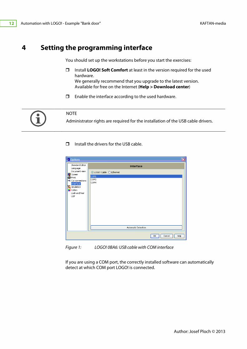
� Install the drivers for the USB cable.
Figure 1: LOGO! 0BA6: USB cable with COM interface
If you are using a COM port, the correctly installed software can automatically
detect at which COM port LOGO! is connected.
-
KAFTAN-media Automation with LOGO! - Example "Bank door" 13
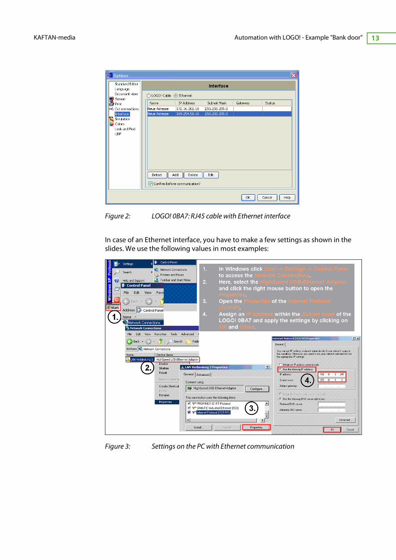
Figure 2: LOGO! 0BA7: RJ45 cable with Ethernet interface
In case of an Ethernet interface, you have to make a few settings as shown in the
slides. We use the following values in most examples:
Figure 3: Settings on the PC with Ethernet communication
Author: Josef Ploch © 2013
Automation with LOGO! - Example "Bank door" KAFTAN-media
14
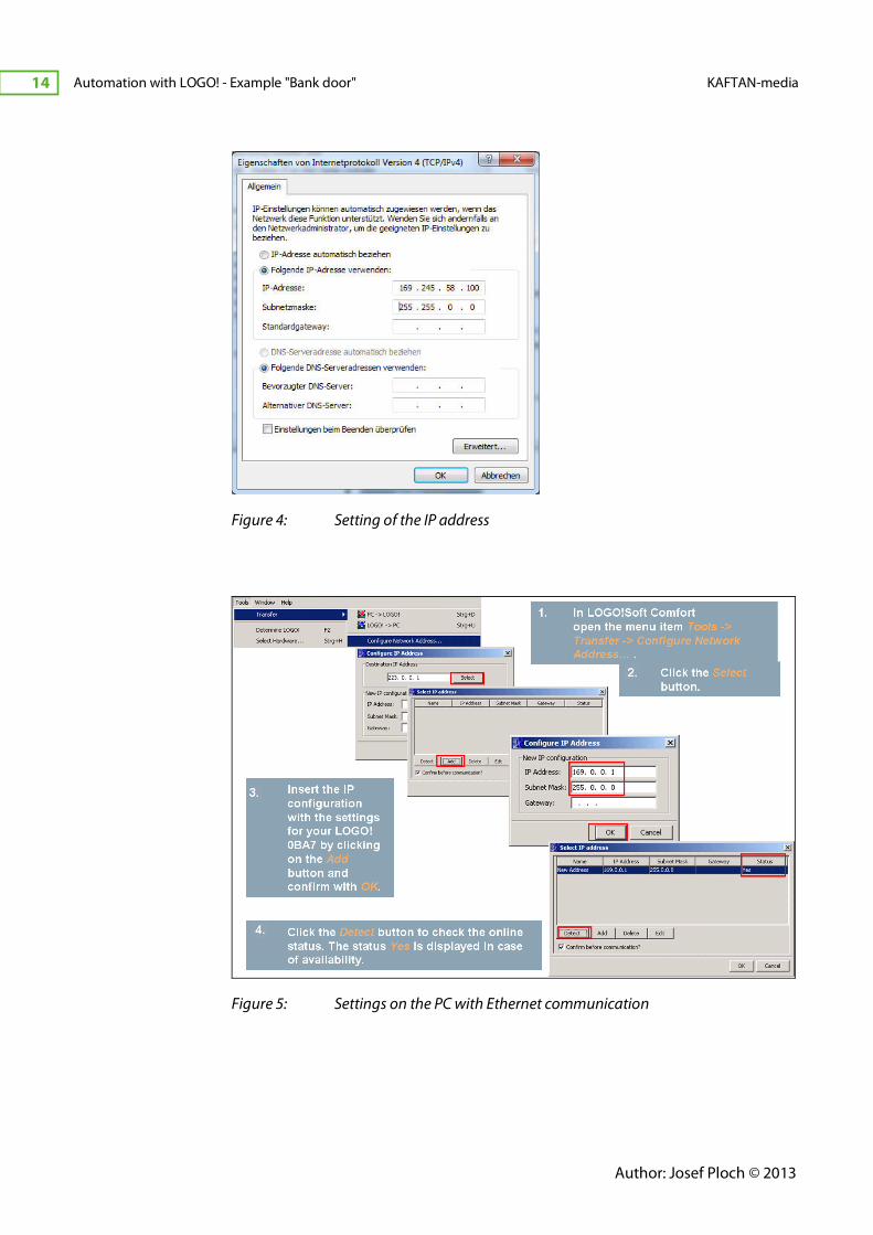
Figure 4: Setting of the IP address
Figure 5: Settings on the PC with Ethernet communication
-
KAFTAN-media Automation with LOGO! - Example "Bank door" 15
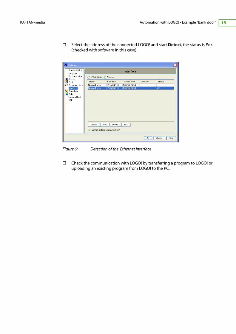
� Select the address of the connected LOGO! and start Detect, the status is Yes
(checked with software in this case).
Figure 6: Detection of the Ethernet interface
� Check the communication with LOGO! by transferring a program to LOGO! or
uploading an existing program from LOGO! to the PC.
Author: Josef Ploch © 2013
Automation with LOGO! - Example "Bank door" KAFTAN-media
16
5 Task 1:
Logic functions "OR" and "NOR"
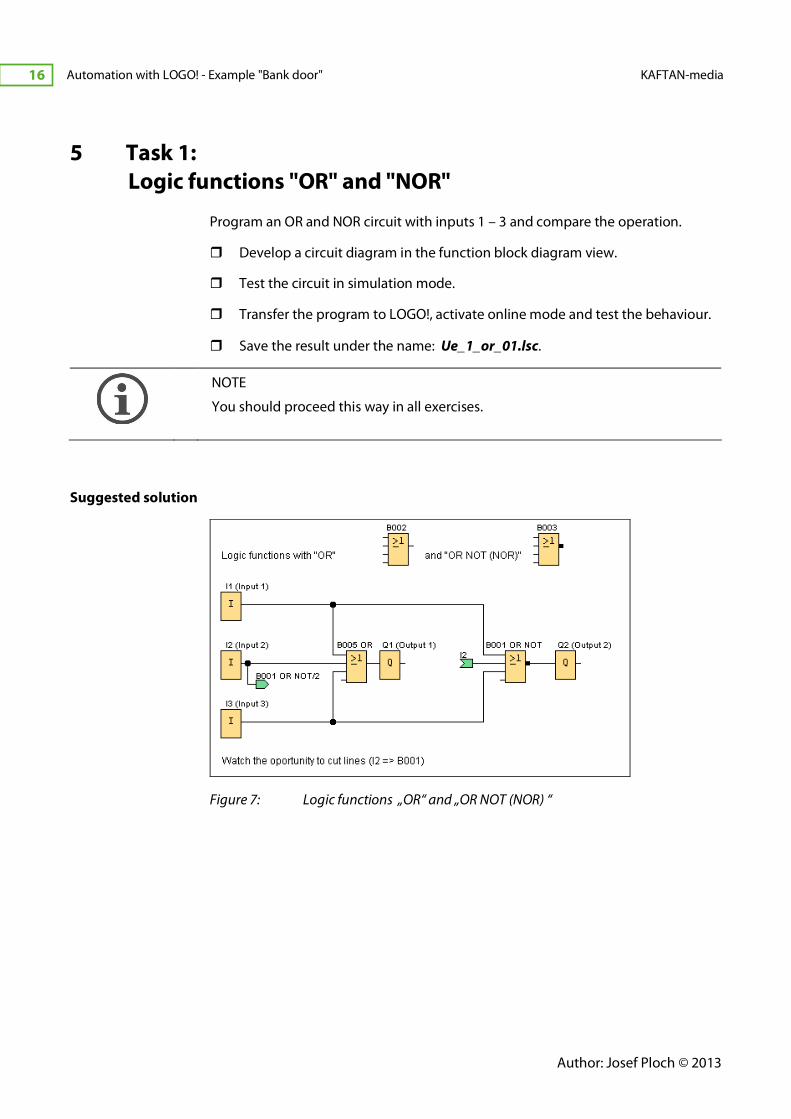
Program an OR and NOR circuit with inputs 1 – 3 and compare the operation.
� Develop a circuit diagram in the function block diagram view.
� Test the circuit in simulation mode.
� Transfer the program to LOGO!, activate online mode and test the behaviour.
� Save the result under the name: Ue_1_or_01.lsc.
NOTE
You should proceed this way in all exercises.
Suggested solution
Figure 7: Logic functions „OR“ and „OR NOT (NOR) “

-
KAFTAN-media Automation with LOGO! - Example "Bank door" 17
6 Task 2:
Logic functions „AND“ and „NAND“
Program an "AND" and "NAND" circuit with inputs 1 – 3 and compare the
operation.
� Proceed as described in task 1.
� Save the result under the name: Ue_2_and_01.lsc
Suggested solution
Figure 8: Logic functions „AND“ and „AND NOT (NAND)“
Author: Josef Ploch © 2013
Automation with LOGO! - Example "Bank door" KAFTAN-media
18
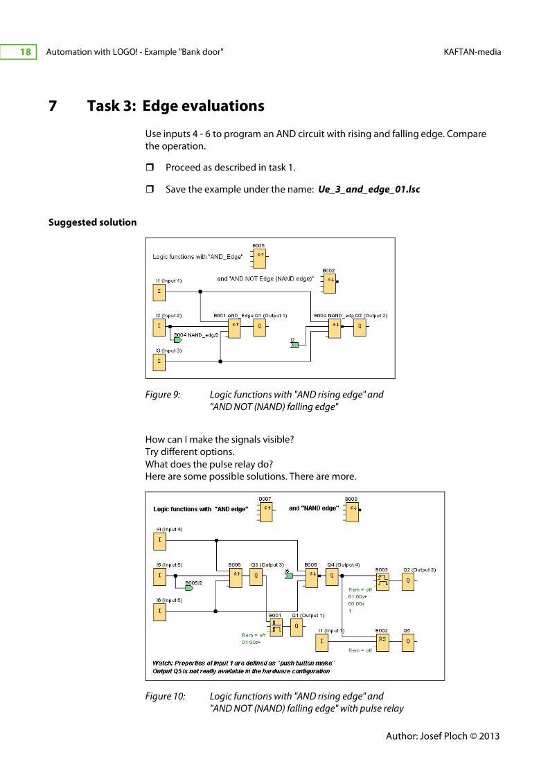
7 Task 3: Edge evaluations
Use inputs 4 - 6 to program an AND circuit with rising and falling edge. Compare
the operation.
� Proceed as described in task 1.
� Save the example under the name: Ue_3_and_edge_01.lsc
Suggested solution
Figure 9: Logic functions with "AND rising edge" and
"AND NOT (NAND) falling edge"
How can I make the signals visible?
Try different options.
What does the pulse relay do?
Here are some possible solutions. There are more.
Figure 10: Logic functions with "AND rising edge" and
"AND NOT (NAND) falling edge" with pulse relay
-
KAFTAN-media Automation with LOGO! - Example "Bank door" 19
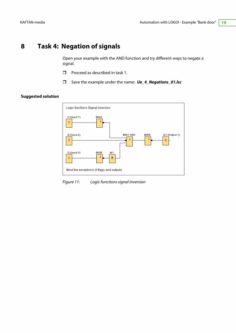
8 Task 4: Negation of signals
Open your example with the AND function and try different ways to negate a
signal.
� Proceed as described in task 1.
� Save the example under the name: Ue_4_Negations_01.lsc
Suggested solution
Figure 11: Logic functions signal inversion
Author: Josef Ploch © 2013
Automation with LOGO! - Example "Bank door" KAFTAN-media
20
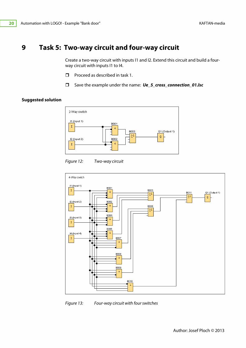
9 Task 5: Two-way circuit and four-way circuit
Create a two-way circuit with inputs I1 and I2. Extend this circuit and build a four-
way circuit with inputs I1 to I4.
� Proceed as described in task 1.
� Save the example under the name: Ue_5_cross_connection_01.lsc
Suggested solution
Figure 12: Two-way circuit
Figure 13: Four-way circuit with four switches
-
KAFTAN-media Automation with LOGO! - Example "Bank door" 21
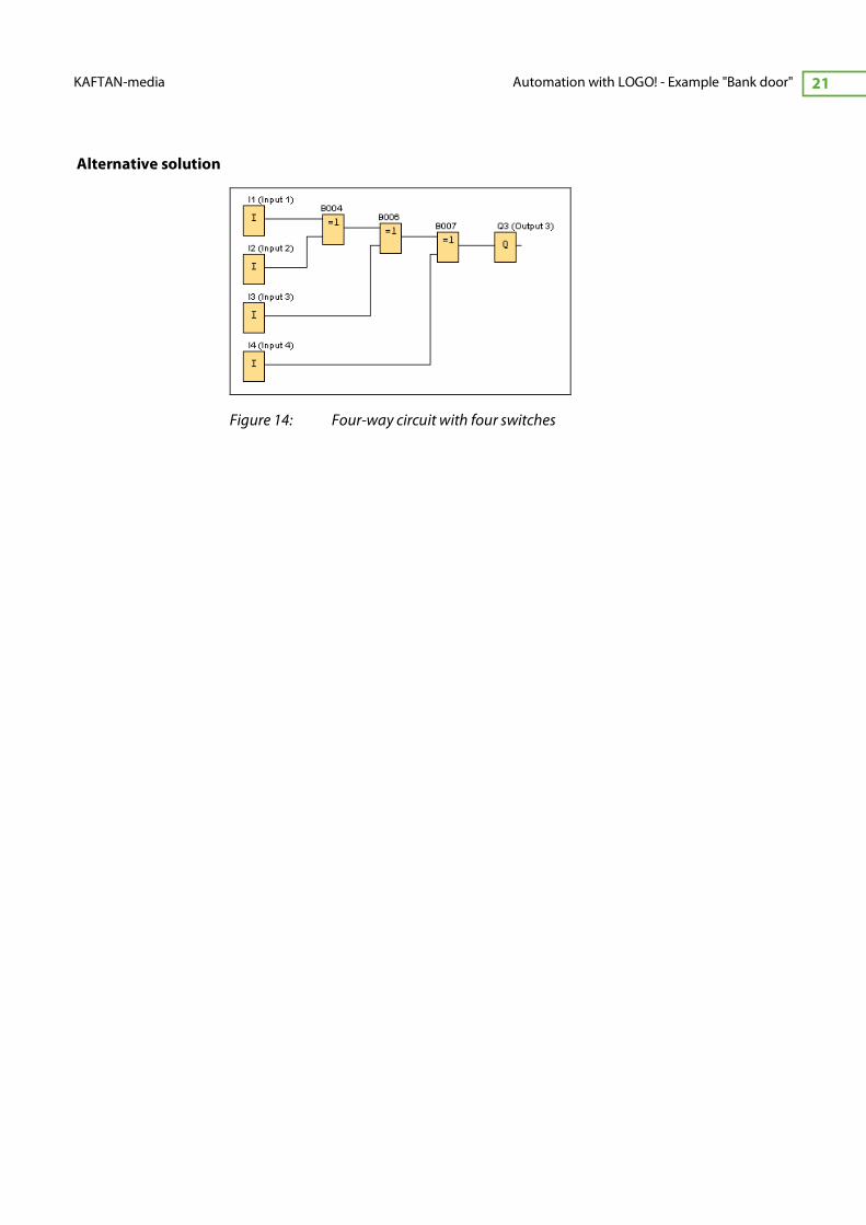
Alternative solution
Figure 14: Four-way circuit with four switches
Author: Josef Ploch © 2013
Automation with LOGO! - Example "Bank door" KAFTAN-media
22
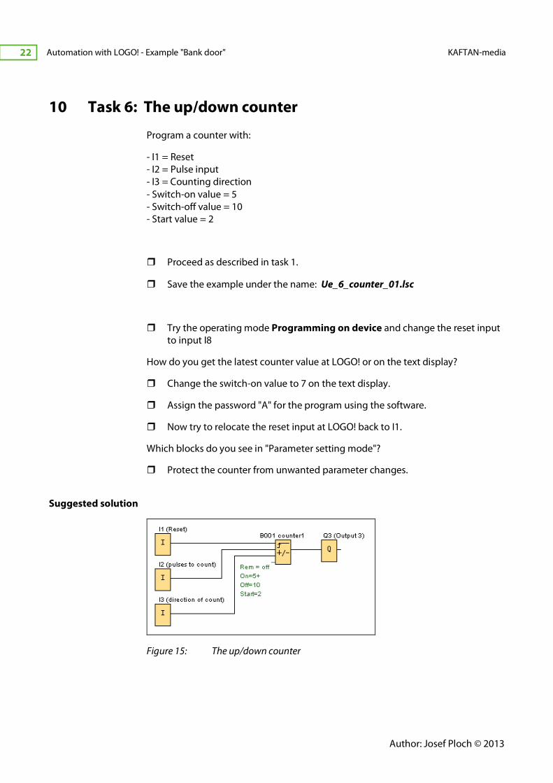
10 Task 6: The up/down counter
Program a counter with:
- I1 = Reset
- I2 = Pulse input
- I3 = Counting direction
- Switch-on value = 5
- Switch-off value = 10
- Start value = 2
� Proceed as described in task 1.
� Save the example under the name: Ue_6_counter_01.lsc
� Try the operating mode Programming on device and change the reset input
to input I8
How do you get the latest counter value at LOGO! or on the text display?
� Change the switch-on value to 7 on the text display.
� Assign the password "A" for the program using the software.
� Now try to relocate the reset input at LOGO! back to I1.
Which blocks do you see in "Parameter setting mode"?
� Protect the counter from unwanted parameter changes.
Suggested solution
Figure 15: The up/down counter
-
KAFTAN-media Automation with LOGO! - Example "Bank door" 23
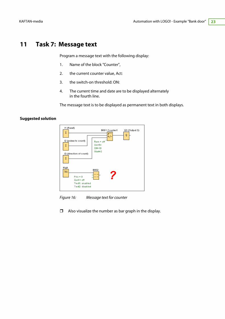
11 Task 7: Message text
Program a message text with the following display:
1. Name of the block "Counter",
2. the current counter value, Act:
3. the switch-on threshold: ON:
4. The current time and date are to be displayed alternately
in the fourth line.
The message text is to be displayed as permanent text in both displays.
Suggested solution
Figure 16: Message text for counter
� Also visualize the number as bar graph in the display.
Author: Josef Ploch © 2013
Automation with LOGO! - Example "Bank door" KAFTAN-media
24
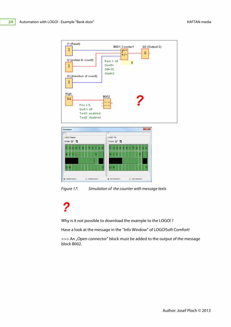
Figure 17: Simulation of the counter with message texts
? Why is it not possible to download the example to the LOGO! ?
Have a look at the message in the “Info Window” of LOGO!Soft Comfort!
>>> An „Open connector“ block must be added to the output of the message
block B002.
-
KAFTAN-media Automation with LOGO! - Example "Bank door" 25
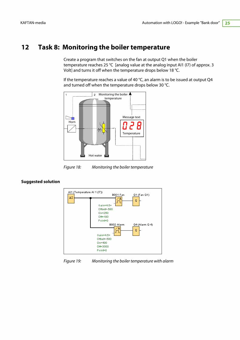
12 Task 8: Monitoring the boiler temperature
Create a program that switches on the fan at output Q1 when the boiler
temperature reaches 25 °C [analog value at the analog input AI1 (I7) of approx. 3
Volt] and turns it off when the temperature drops below 18 °C.
If the temperature reaches a value of 40 °C, an alarm is to be issued at output Q4
and turned off when the temperature drops below 30 °C.
Figure 18: Monitoring the boiler temperature
Suggested solution
Figure 19: Monitoring the boiler temperature with alarm
Monitoring the boiler
temperature
Horn
Hot water
Temperature
Message text

Author: Josef Ploch © 2013
Automation with LOGO! - Example "Bank door" KAFTAN-media
26
13 Task 9: Analog value with message text, alarm with
acknowledgment
Amend the program from task 8 by the following functions:
A message text is generally displayed with the current time and latest temperature.
An alarm window should display the following in case of an alarm:
� "Temperature alarm"
� Act: Temperature value
� Number of alarms
� Date and time of the first alarm
The backlighting of the message window should flash. The error must be
acknowledged in LOGO! or on the display.
Suggested solution with message text
Figure 20: Analog value with message text, alarm with acknowledgment
Figure 21: Display of the message texts
-
KAFTAN-media Automation with LOGO! - Example "Bank door" 27
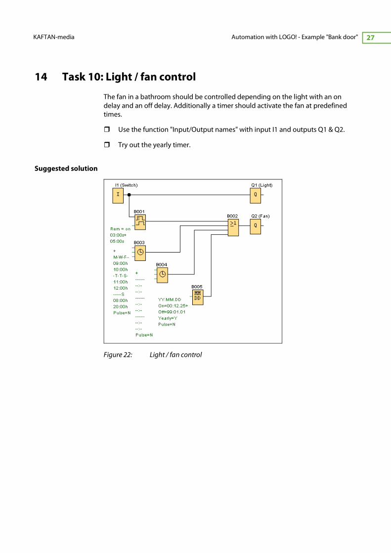
14 Task 10: Light / fan control
The fan in a bathroom should be controlled depending on the light with an on
delay and an off delay. Additionally a timer should activate the fan at predefined
times.
� Use the function "Input/Output names" with input I1 and outputs Q1 & Q2.
� Try out the yearly timer.
Suggested solution
Figure 22: Light / fan control
Author: Josef Ploch © 2013
Automation with LOGO! - Example "Bank door" KAFTAN-media
28
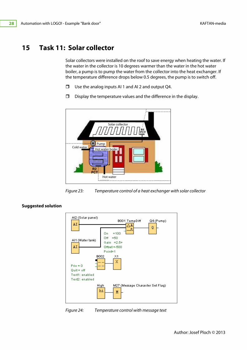
15 Task 11: Solar collector
Solar collectors were installed on the roof to save energy when heating the water. If
the water in the collector is 10 degrees warmer than the water in the hot water
boiler, a pump is to pump the water from the collector into the heat exchanger. If
the temperature difference drops below 0.5 degrees, the pump is to switch off.
� Use the analog inputs AI 1 and AI 2 and output Q4.
� Display the temperature values and the difference in the display.
Figure 23: Temperature control of a heat exchanger with solar collector
Suggested solution
Figure 24: Temperature control with message text
Hot water
Cold water
Solar collector
Hot water boiler
Pump
-
KAFTAN-media Automation with LOGO! - Example "Bank door" 29
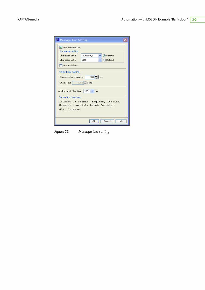
Figure 25: Message text setting

Author: Josef Ploch © 2013
Automation with LOGO! - Example "Bank door" KAFTAN-media
30
16 Task 12: Light settings in the conference room
The light in a conference room is to be dimmed in three permanently set steps. It
will be turned on with a switch at input I3. Step selection takes place through
switches at inputs I1 and I2. In manual operation, the operating personnel would
like to set any brightness level with a potentiometer. The set point should be
assigned to analog input AQ1. As we have no analog output in our demo lit, we
want to see the set point as a bar graph in the display. It should also show if manual
mode is activated.
S1 = 0 + S2 = 0 => 200 %
S1 = 1 + S2 = 0 => 600 %
S1 = 1 + S2 = 1 => 900 %
S1 = 0 + S2 = 1 => manual operation
Suggested solution
Figure 26: Light settings in the conference room with manual operation

-
KAFTAN-media Automation with LOGO! - Example "Bank door" 31
Figure 27: Display with automatic operation
Author: Josef Ploch © 2013
Automation with LOGO! - Example "Bank door" KAFTAN-media
32
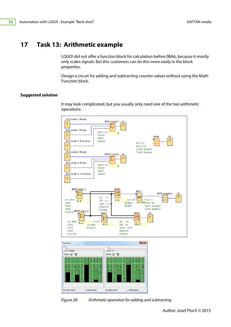
17 Task 13: Arithmetic example
LOGO! did not offer a function block for calculation before 0BA6, because it mostly
only scales signals. But this customers can do this more easily in the block
properties.
Design a circuit for adding and subtracting counter values without using the Math
Function block.
Suggested solution
It may look complicated, but you usually only need one of the two arithmetic
operations.
Figure 28: Arithmetic operation for adding and subtracting

-
KAFTAN-media Automation with LOGO! - Example "Bank door" 33
By the way, the solution also includes the basic approach to multiplication and
division.
Do you see the solution?

Author: Josef Ploch © 2013
Automation with LOGO! - Example "Bank door" KAFTAN-media
34
18 Functional model: Bank door
Figure 29: Functional model "Bank door" (Fischer-Technik)
18.1 Introduction
Our model simulates the function of a modern automatic sliding door that is
typically used in businesses or banks.
We are looking at a bank door in our example. The customer opens the door from
the outside with a "bank card". The door is to close automatically afterwards. When
leaving the bank, the door opens automatically triggered by a sensor when the
customer approaches the door. We are using a light barrier in our case. With a
LOGO! text display, the door can be opened and closed manually.
The "card reader" only admits customers during regular banking hours. Customers
who are still inside the bank at the end of regular business hours should be able to
leave the building without any problems. For security reasons, the number of
customers inside the bank is not to exceed a maximum value. Once this value is
reached, the card reader is blocked until a few customers have left the bank and
the card reader is activated once again.
We are going to develop a program in several steps. Please keep in mind that we
do not have to use all safety devices in our exercises (as is the case in actual
applications). We are only working on understanding the operating principle.
-
KAFTAN-media Automation with LOGO! - Example "Bank door" 35
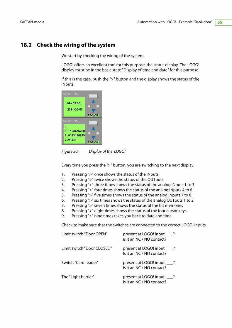
18.2 Check the wiring of the system
We start by checking the wiring of the system.
LOGO! offers an excellent tool for this purpose, the status display. The LOGO!
display must be in the basic state "Display of time and date" for this purpose.
If this is the case, push the ">" button and the display shows the status of the
INputs.
Figure 30: Display of the LOGO!
Every time you press the ">" button, you are switching to the next display.
1. Pressing ">" once shows the status of the INputs
2. Pressing ">" twice shows the status of the OUTputs
3. Pressing ">" three times shows the status of the analog INputs 1 to 3
4. Pressing ">" four times shows the status of the analog INputs 4 to 6
5. Pressing ">" five times shows the status of the analog INputs 7 to 8
6. Pressing ">" six times shows the status of the analog OUTputs 1 to 2
7. Pressing ">" seven times shows the status of the bit memories
8. Pressing ">" eight times shows the status of the four cursor keys
9. Pressing ">" nine times takes you back to date and time
Check to make sure that the switches are connected to the correct LOGO! inputs.
Limit switch "Door OPEN" present at LOGO! input I___?
Is it an NC / NO contact?
Limit switch "Door CLOSED" present at LOGO! input I___?
Is it an NC / NO contact?
Switch "Card reader" present at LOGO! input I___?
Is it an NC / NO contact?
The "Light barrier" present at LOGO! input I___?
Is it an NC / NO contact?

Author: Josef Ploch © 2013
Automation with LOGO! - Example "Bank door" KAFTAN-media
36
18.3 Input/Output names
Before we start the program, name your inputs/outputs.
� To do so, press Edit > Input/Output names
� Fill in the table as shown below:
Figure 31: Table of the connector names

-
KAFTAN-media Automation with LOGO! - Example "Bank door" 37
Function test of drive and limit switches
Apply the following program structure to receive a uniform program later:
Figure 32: Program structure
Direction control
This means direction control takes place through pulses and the motor runs in this
direction until it is stopped by a stop pulse.
Figure 33: Direction control
Author: Josef Ploch © 2013
Automation with LOGO! - Example "Bank door" KAFTAN-media
38
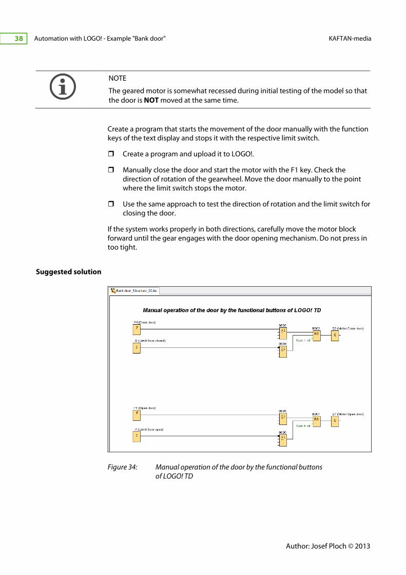
NOTE
The geared motor is somewhat recessed during initial testing of the model so that
the door is NOT moved at the same time.
Create a program that starts the movement of the door manually with the function
keys of the text display and stops it with the respective limit switch.
� Create a program and upload it to LOGO!.
� Manually close the door and start the motor with the F1 key. Check the
direction of rotation of the gearwheel. Move the door manually to the point
where the limit switch stops the motor.
� Use the same approach to test the direction of rotation and the limit switch for
closing the door.
If the system works properly in both directions, carefully move the motor block
forward until the gear engages with the door opening mechanism. Do not press in
too tight.
Suggested solution
Figure 34: Manual operation of the door by the functional buttons
of LOGO! TD
-
KAFTAN-media Automation with LOGO! - Example "Bank door" 39
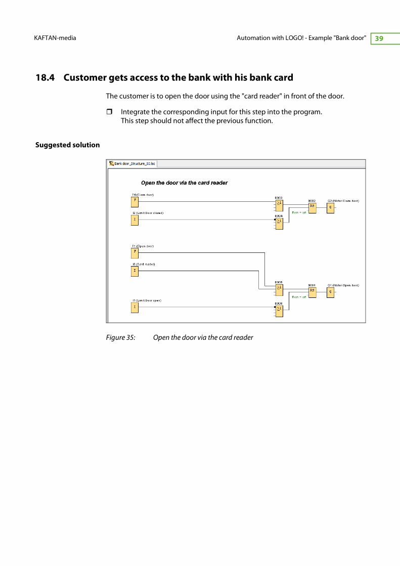
18.4 Customer gets access to the bank with his bank card
The customer is to open the door using the "card reader" in front of the door.
� Integrate the corresponding input for this step into the program.
This step should not affect the previous function.
Suggested solution
Figure 35: Open the door via the card reader

Author: Josef Ploch © 2013
Automation with LOGO! - Example "Bank door" KAFTAN-media
40
18.5 Automatic, time controlled closing of the door
The door is to close automatically. Because we have no sensors that detect if
someone is still standing in the door, the door is to close automatically 5 seconds
after it has opened completely.
What happens when you activate the card reader while the door is closing?
How can you prevent this from happening?
(see solution of the next exercise)
Suggested solution
Figure 36: Automatic closing of the door

-
KAFTAN-media Automation with LOGO! - Example "Bank door" 41
18.6 Door opens automatically to let the customer exit
If a customer wants to leave the bank, the door is to open automatically as soon as
the customer enters the sensor range (light barrier). The door closes automatically
again after 5 seconds.
The light barrier must be activated by turning on the bulb via Q3. If the light is on
the sensor input I4 should give a “1” signal as long as the light beam reaches the
sensor.
Suggested solution
Figure 37: Door opens automatically to let the customer exit
Why does the door open when you start LOGO! ?
How can we avoid this ?
(see solution of the next exercise: flag M8 and message text B008)

Author: Josef Ploch © 2013
Automation with LOGO! - Example "Bank door" KAFTAN-media
42
18.7 Customer can only enter during banking hours
Now the customer can only open the door during regular banking hours.
It must still be possible to open the door manually from the inside and to leave the
bank after hours.
Business hours:
Mo – Fr : 9:00 p.m. to 3:00 a.m.
Sa : 9:00 to 12:00 p.m.
Suggested solution
Figure 38: Customer can only enter during banking hours
-
KAFTAN-media Automation with LOGO! - Example "Bank door" 43
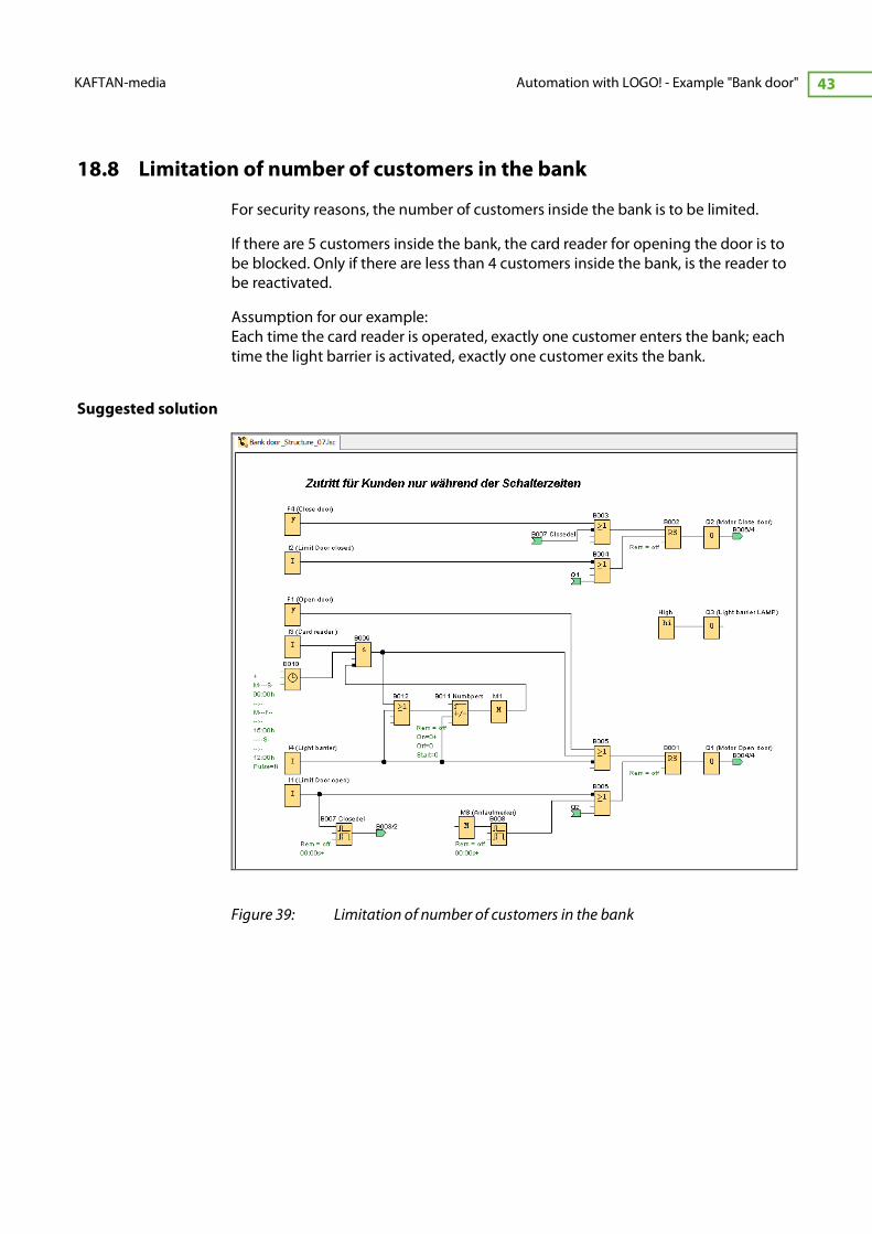
18.8 Limitation of number of customers in the bank
For security reasons, the number of customers inside the bank is to be limited.
If there are 5 customers inside the bank, the card reader for opening the door is to
be blocked. Only if there are less than 4 customers inside the bank, is the reader to
be reactivated.
Assumption for our example:
Each time the card reader is operated, exactly one customer enters the bank; each
time the light barrier is activated, exactly one customer exits the bank.
Suggested solution
Figure 39: Limitation of number of customers in the bank
Author: Josef Ploch © 2013
Automation with LOGO! - Example "Bank door" KAFTAN-media
44
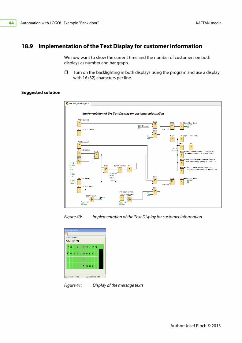
18.9 Implementation of the Text Display for customer information
We now want to show the current time and the number of customers on both
displays as number and bar graph.
� Turn on the backlighting in both displays using the program and use a display
with 16 (32) characters per line.
Suggested solution
Figure 40: Implementation of the Text Display for customer information
Figure 41: Display of the message texts

-
KAFTAN-media Automation with LOGO! - Example "Bank door" 45
We have come to the end of our programming for the functional model "Bank
door".
You can now try out many more LOGO! functions using this example.
� Password protection
� Changing parameters in parameter mode
� Protecting parameters
� Changing special parameters despite parameter protection
� Saving values in case of a power outage
� Setting the maximum number of customers with "potentiometer" (depending
on daily available personnel)
� And so much more.
Author: Josef Ploch © 2013
Automation with LOGO! - Example "Bank door" KAFTAN-media
46
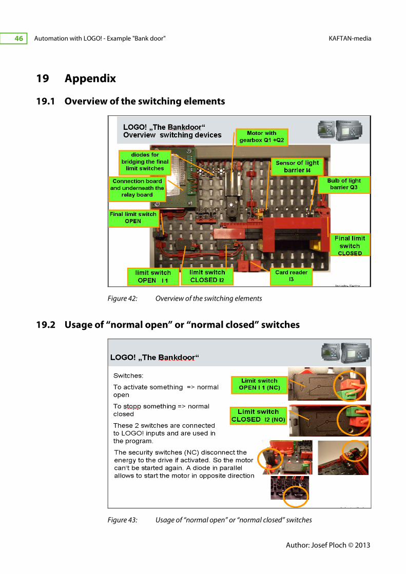
19 Appendix
19.1 Overview of the switching elements
Figure 42: Overview of the switching elements
19.2 Usage of “normal open” or “normal closed” switches
Figure 43: Usage of “normal open” or “normal closed” switches

-
KAFTAN-media Automation with LOGO! - Example "Bank door" 47
19.3 Function of the relay board for motor control
Figure 44: Function of the relay board for motor control
19.4 Design of the training kit LOGO! Learn Advanced
Figure 45: Construction of the training device LOGO! Learn Advanced

Author: Josef Ploch © 2013
Automation with LOGO! - Example "Bank door" KAFTAN-media
48
20 References
[1] Online help of the software Siemens LOGO!Soft Comfort V7.0
[2] Kaftan, J.: LOGO! Course (German). Vogel Business Media, 2009


