AUTOMATION: Automation is the use of control systems such as computers to control industrial machinery and processes, replacing human operators. In the scope of industrialization, it is a step beyond mechanization. Whereas mechanization provided human operators with machinery to assist them with the physical requirements of work, automation greatly reduces the need for human sensory and mental requirements as well. ADVANTAGES OF AUTOMATION: The purpose of automation has shifted from increasing productivity and reducing costs, to broader issues, such as increasing quality and flexibility in the manufacturing process. Automation is now often applied primarily to increase quality in the manufacturing process, where automation can increase quality substantially. For example, automobile and truck pistons used to be installed into engines manually. This is rapidly being transitioned to automated machine installation, because the error rate for manual installment was around 1-1.5%, but has been reduced to 0.00001% with automation. Hazardous operations, such as oil refining, the manufacturing of industrial chemicals, and all forms of metal working, were always early contenders for automation. Application of Automation Power generation
Transcript
AUTOMATION: Automation is the use of control systems such as computers to control
industrial machinery and processes, replacing human operators. In the scope of industrialization, it is a step beyond mechanization. Whereas mechanization provided human operators with machinery to assist them with the physical requirements of work, automation greatly reduces the need for human sensory and mental requirements as well.
ADVANTAGES OF AUTOMATION:
The purpose of automation has shifted from increasing productivity and reducing costs, to broader issues, such as increasing quality and flexibility in the manufacturing process.
Automation is now often applied primarily to increase quality in the manufacturing process, where automation can increase quality substantially.
For example, automobile and truck pistons used to be installed into engines manually. This is rapidly being transitioned to automated machine installation, because the error rate for manual installment was around 1-1.5%, but has been reduced to 0.00001% with automation.
Hazardous operations, such as oil refining, the manufacturing of industrial chemicals, and all forms of metal working, were always early contenders for automation.
Application of AutomationPower generation
TRANSMISSION AND DISTRIBUTION:
Oil and gas industries
Process industries
Building automation
HISTORY OF AUTOMATION
MANUAL CONTROL
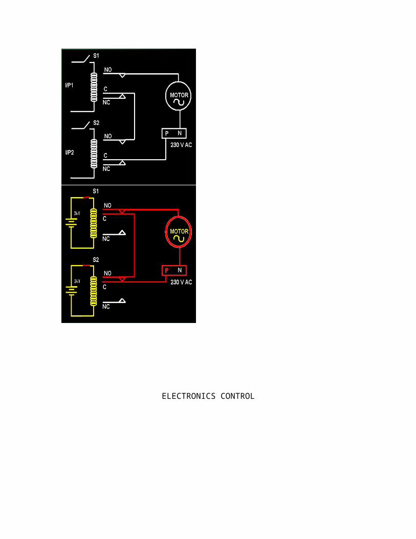
HARDWIRED CONTROL:Prior to PLCs, many of these control tasks were solved with contactor or
relay controls. This is often referred to as hard-wired control. Circuit diagrams had to be designed, electrical components specified and installed, and wiring lists created. Electricians would then wire the components necessary to perform a specific task. If an error was made the wires had to be reconnected correctly. A change in function or system expansion required extensive component changes and rewiring.
DRAWBACKS:Bulky and complex wiring.Difficult to change the logic.Unreliable.
RELAY :
RELAY LOGIC – AND GATE:
ELECTRONICS CONTROL
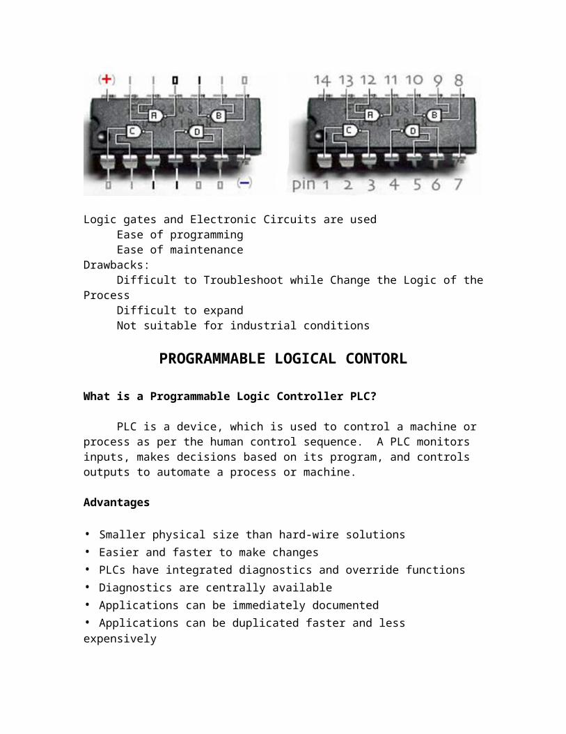
Logic gates and Electronic Circuits are usedEase of programmingEase of maintenance
Drawbacks:Difficult to Troubleshoot while Change the Logic of the ProcessDifficult to expandNot suitable for industrial conditions
PROGRAMMABLE LOGICAL CONTORL
What is a Programmable Logic Controller PLC?
PLC is a device, which is used to control a machine or process as per the human control sequence. A PLC monitors inputs, makes decisions based on its program, and controls outputs to automate a process or machine.
Advantages
• Smaller physical size than hard-wire solutions• Easier and faster to make changes• PLCs have integrated diagnostics and override functions• Diagnostics are centrally available• Applications can be immediately documented• Applications can be duplicated faster and less expensively
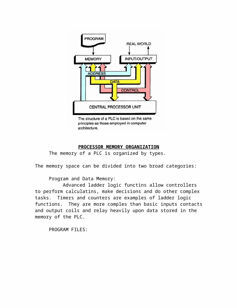
PROCESSOR MEMORY ORGANIZATIONThe memory of a PLC is organized by types.
The memory space can be divided into two broad categories:
Program and Data Memory:Advanced ladder logic functins allow controllers to perform calculatins,
make decisions and do other complex tasks. Timers and counters are examples of ladder logic functions. They are more comples than basic inputs contacts and output coils and relay heavily upon data stored in the memory of the PLC.
PROGRAM FILES:
The user program will account for most of the memory of a PLC
system.Program files contain the logic controlling machine operation.
This logic consistes of instructions that are programmed in a ladder logic format.
DATA FILES:
The data file protion of memory stores input and output status, processor status, the status of various bits and numerical data.
INPUT TABLE FILE OPERATION:
Processor continually reads current input status and updates input
image table file.
OUTPUT TABLE FILE OPERATION:
Processor continually activates or deactivates ouput status according to output image table file status
PROGRAM SCAN:During each operating cycle, the processor reads all inputs, takes these
values, and energizes or de-energizes the outputs according to the user program. This process is known as a scan. Because the inputs can change at any time, the PLC must carry on this process continuously.
1. I/O scan – records status data of input devices. Energizes output devices that have their associated status bits set to ON (1)
2. Program scan – instruction are executed sequentially.
SCAN PROCESS:
The scan time indicates how fast the controller can react to changes in inputs. Scan times vary with computer model and program content, and length. If a controller has to react to an input signal that changes states twice during the scan time, it is possible that the PLC will never be able to detect this change.
When the inputs is closed, the input module senses a voltage and an ON condition (1) is entered into the input table bit ‘0012’.
During the program scan the processor sets instructins ‘0012’ and ‘506’ to ON(1).
The processor turns light output ‘506’ ON during the next I/O scan.
KEYENCE
ADDRESS:
INPUTS:0000 to 00150100 to 01150200 to 02150300 to 03150400 to 0415
OUTPUTS:0500 to 05150600 to 06150700 to 07150800 to 08150900 to 0915
INTERNAL MEMORY BIT:1000 to 1015
Upto1900 to 1915
TIMERS:TMR<add> space #<time> (0.1sec)TMH<add> space #<time> (0.01sec)TMS<add> space #<time> (0.001sec)
COUNTERS:Up counter: C<add> space #<number of count>space<internal bit>Up/Dwn counter: C<add>space#<number of count>
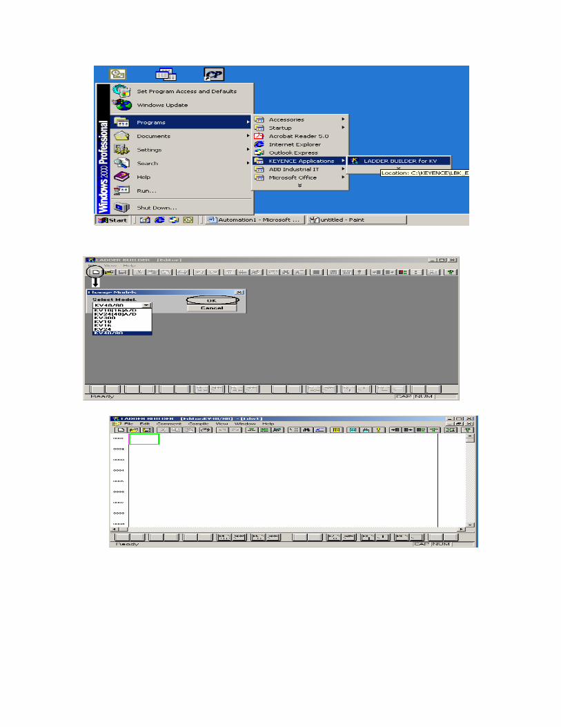
PROCEDURE FOR PROGRAMMING:
1 2 3 4 5 6 7 8 9 10 11 12 13 14 15 16
01. Edit command/Lable02. Edit line command03. Show/Hide command04. Jump to specified line/step05. Find06. Replace operand 07. Usage information 08. Edit list09. compail10. Show compilation error11. Transfer to PLC
12. Read from PLC 13. Plc monitor14. Simulator15. Display mode16. Description of operation
1 2 3 4 5 6 7 8 9 10
01. N.O. contact OR input02. NC contact OR input03. NO contact input04. NC contact input 05. Output coil06. NC output coil07. Input vertical connection line08. Delete vertical connection line09. Input Horizontal connection line10. Delete Horizontal connection line
BASIC PROGRAMMES:
--| |-- NORMALY OPEN CONTACT
--| / |-- NORMALY CLOSED CONTACT
--( )-- COIL
EX: 1When the switch (SW) is ON, the LOAD should ON (Rung 0001)When the switch (SW) is OFF, the LOAD should ON (Rung 0002
Note: The all programming sequence should complete with ‘END’ AND ‘ENDH’.