Page 1
AUTOMOBILE MECHATRONICS
Basics of Electrical and Electronics Engg.
UNIT-3
DC Generator:
A dc generator is an electrical machine which converts mechanical energy into direct current
electricity. This energy conversion is based on the principle of production of dynamically induced
emf. This article outlines basic construction and working of a DC generator.
Construction Of A DC Machine:
A DC generator can be used as a DC motor without any constructional changes and vice versa is
also possible. Thus, a DC generator or a DC motor can be broadly termed as a DC machine. These
basic constructional details are also valid for the construction of a DC motor. Hence, let's call
this point as construction of a DC machine instead of just 'construction of a dc generator'.
The above figure shows constructional details of a simple 4-pole DC machine. A DC machine consists of two basic parts; stator and rotor. Basic constructional parts of a DC machine are described below.
Page 2
1. Yoke: The outer frame of a dc machine is called as yoke. It is made up of cast iron or steel.
It not only provides mechanical strength to the whole assembly but also carries the magnetic
flux produced by the field winding.
2. Poles and pole shoes: Poles are joined to the yoke with the help of bolts or welding. They
carry field winding and pole shoes are fastened to them. Pole shoes serve two purposes; (i)
they support field coils and (ii) spread out the flux in air gap uniformly.
3. Field winding: They are usually made of copper. Field coils are former wound and placed
on each pole and are connected in series. They are wound in such a way that, when energized,
they form alternate North and South poles.
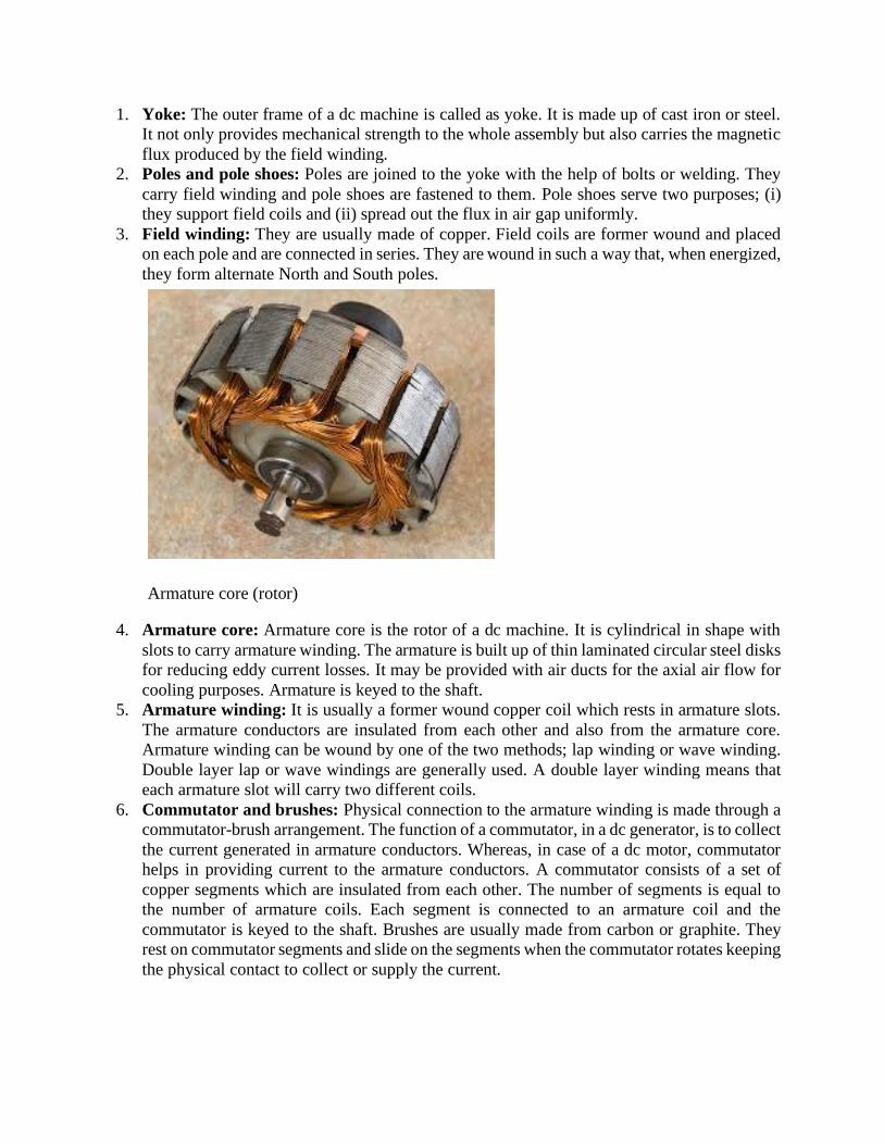
Armature core (rotor)
4. Armature core: Armature core is the rotor of a dc machine. It is cylindrical in shape with
slots to carry armature winding. The armature is built up of thin laminated circular steel disks
for reducing eddy current losses. It may be provided with air ducts for the axial air flow for
cooling purposes. Armature is keyed to the shaft.
5. Armature winding: It is usually a former wound copper coil which rests in armature slots.
The armature conductors are insulated from each other and also from the armature core.
Armature winding can be wound by one of the two methods; lap winding or wave winding.
Double layer lap or wave windings are generally used. A double layer winding means that
each armature slot will carry two different coils.
6. Commutator and brushes: Physical connection to the armature winding is made through a
commutator-brush arrangement. The function of a commutator, in a dc generator, is to collect
the current generated in armature conductors. Whereas, in case of a dc motor, commutator
helps in providing current to the armature conductors. A commutator consists of a set of
copper segments which are insulated from each other. The number of segments is equal to
the number of armature coils. Each segment is connected to an armature coil and the
commutator is keyed to the shaft. Brushes are usually made from carbon or graphite. They
rest on commutator segments and slide on the segments when the commutator rotates keeping
the physical contact to collect or supply the current.
Page 3
Working Principle Of A DC Generator:
According to Faraday’s laws of electromagnetic induction, whenever a conductor is placed in a
varying magnetic field (OR a conductor is moved in a magnetic field), an emf (electromotive force)
gets induced in the conductor. The magnitude of induced emf can be calculated from the emf
equation of dc generator. If the conductor is provided with a closed path, the induced current will
circulate within the path. In a DC generator, field coils produce an electromagnetic field and the
armature conductors are rotated into the field. Thus, an electromagnetically induced emf is
generated in the armature conductors. The direction of induced current is given by Fleming’s right
hand rule.
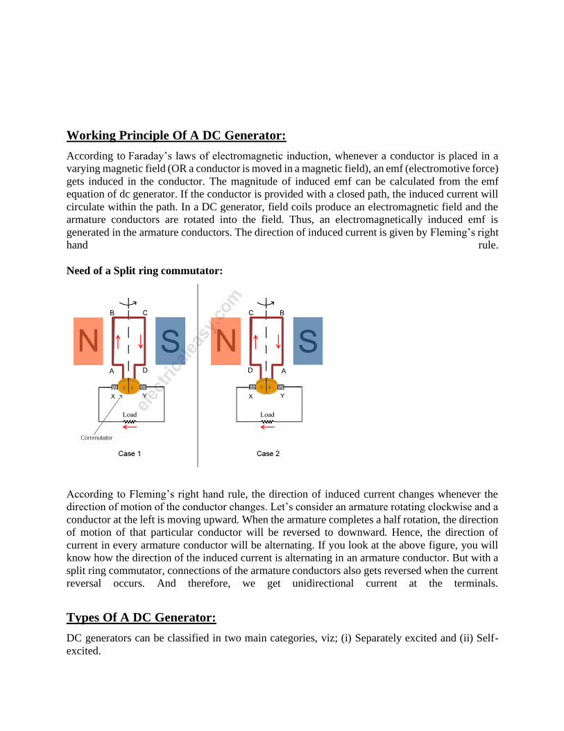
Need of a Split ring commutator:
According to Fleming’s right hand rule, the direction of induced current changes whenever the
direction of motion of the conductor changes. Let’s consider an armature rotating clockwise and a
conductor at the left is moving upward. When the armature completes a half rotation, the direction
of motion of that particular conductor will be reversed to downward. Hence, the direction of
current in every armature conductor will be alternating. If you look at the above figure, you will
know how the direction of the induced current is alternating in an armature conductor. But with a
split ring commutator, connections of the armature conductors also gets reversed when the current
reversal occurs. And therefore, we get unidirectional current at the terminals.
Types Of A DC Generator:
DC generators can be classified in two main categories, viz; (i) Separately excited and (ii) Self-
excited.
Page 4
(i) Separately excited: In this type, field coils are energized from an independent external DC
source.
(ii) Selfexcited: In this type, field coils are energized from the current produced by the generator
itself. Initial emf generation is due to residual magnetism in field poles. The generated emf causes
a part of current to flow in the field coils, thus strengthening the field flux and thereby increasing
emf generation. Self excited dc generators can further be divided into three types -
(a) Series wound - field winding in series with armature winding
(b) Shunt wound - field winding in parallel with armature winding
(c) Compound wound - combination of series and shunt winding
Emf Equation of a DC Generator:
As the armature rotates, a voltage is generated in its coils. In the case of a generator,
the emf of rotation is called the Generated emf or Armature emfand is denoted as Er =
Eg. In the case of a motor, the emf of rotation is known as Back emf or Counter
emf and represented as Er = Eb.The expression for emf is same for both the
operations. I.e., for Generator as well as for Motor.
Derivation of EMF Equation of a DC Machine – Generator and Motor
Let,
• P – Number of poles of the machine
• ϕ – Flux per pole in Weber.
• Z – Total number of armature conductors.
• N – Speed of armature in revolution per minute (r.p.m).
• A – Number of parallel paths in the armature winding.
In one revolution of the armature, the flux cut by one conductor is given as
Time taken to complete one revolution is given as
Therefore, the average induced e.m.f in one conductor will be
Page 5
Putting the value of (t) from Equation (2) in the equation (3) we will get
The number of conductors connected in series in each parallel path = Z/A.
Therefore, the average induced e.m.f across each parallel path or the armature
terminals is given by the equation shown below.
Where n is the speed in revolution per second (r.p.s) and given as
For a given machine, the number of poles and the number of conductors per parallel
path (Z/A) are constant. Hence, the equation (5) can be written as
Where, K is a constant and given as
Page 6
Therefore, the average induced emf equation can also be written as
Where K1 is another constant and hence induced emf equation can be written as
Where ω is the angular velocity in radians/second is represented as
Thus, it is clear that the induced emf is directly proportional to the speed and flux
per pole. The polarity of induced emf depends upon the direction of the magnetic
field and the direction of rotation. If either of the two is reverse the polarity changes,
but if two are reversed the polarity remains unchanged.
This induced emf is a fundamental phenomenon for all the DC Machines whether
they are working as a generator or motor.
If the machine DC Machine is working as a Generator, the induced emf is given by
the equation shown below.
Page 7
Where Eg is the Generated Emf
If the machine DC Machine is working as a Motor, the induced emf is given by the
equation shown below.
In a motor, the induced emf is called Back Emf (Eb) because it acts opposite to the
supply voltage.
Applications of DC Generators:
There are various types of DC generators available for several types of services. The
applications of these DC generators based on their characteristic are discussed below:
Applications of Separately Excited DC Generators:
This type of DC generators are generally more expensive than self-excited DC
generators because of their requirement of separate excitation source. Because of that
their applications are restricted. They are generally used where the use of self-excited
generators are unsatisfactory.
1. Because of their ability of giving wide range of voltage output, they are generally
used for testing purpose in the laboratories.
2. Separately excited generators operate in a stable condition with any variation in
field excitation. Because of this property they are used as supply source of DC
motors, whose speeds are to be controlled for various applications. Example-
Ward Leonard Systems of speed control.
Applications of Shunt Wound DC Generators:
The application of shunt generators is very much restricted for its dropping voltage
characteristic. They are used to supply power to the apparatus situated very close to its
Page 8
position. These type of DC generators generally give constant terminal voltage for small
distance operation with the help of field regulators from no load to full load.
1. They are used for general lighting.
2. They are used to charge battery because they can be made to give constant output
voltage.
3. They are used for giving the excitation to the alternators.
4. They are also used for small power supply (such as a portable generator).
Applications of Series Wound DC Generators:
These types of generators are restricted for the use of power supply because of their
increasing terminal oltage characteristic with the increase in load current from no load
to full load. We can clearly see this characteristic from the characteristic curve of series
wound generator. They give constant current in the dropping portion of the
characteristic curve. For this property they can be used as constant current source and
employed for various applications.
1. They are used for supplying field excitation current in DC locomotives for
regenerative breaking.
2. This types of generators are used as boosters to compensate the voltage drop in
the feeder in various types of distribution systems such as railway service.
3. In series arc lightening this type of generators are mainly used.
Applications of Compound Wound DC Generators:
Among various types of DC generators, the compound wound DC generators are most
widely used because of its compensating property. Depending upon number of series
field turns, the cumulatively compounded generators may be over compounded, flat
compounded and under compounded. We can get desired terminal voltage by
compensating the drop due to armature reaction and ohmic drop in the in the line. Such
generators have various applications.
1. Cumulative compound wound generators are generally used for lighting, power
supply purpose and for heavy power services because of their constant voltage
property. They are mainly made over compounded.
2. Cumulative compound wound generators are also used for driving a motor.
3. For small distance operation, such as power supply for hotels, offices, homes and
lodges, the flat compounded generators are generally used.
4. The differential compound wound generators, because of their large
demagnetization armature reaction, are used for arc welding where huge voltage
drop and constant current is required.
Page 9
At present time the applications of DC generators become very limited because of
technical and economic reasons. Now a days the electric power is mainly generated in
the form of alternating current with the help of various power electronics devices.
Advantages:
Advantages of the DC generators are very few like ease of parallel operation, simple design and
construction and lesser system stability issues unlike the alternators.
Disadvantages:
Inherently, both AC and DC generators work on the Faraday's law of electromagnetic induction.
When the conductor cuts the magnetic field, emf is induced in it. Now, the voltage induced in the
armature of the DC generator is AC, but that is converted to the Dc form through the
Commutator. So, basically that converted voltage is supplied to the load through the brush and
slip ring assembly.
Now, we don't need any stats for the discussion, as we can conclude by the qualitative analysis
that DC generators are less efficient than the AC generators due to the reason that is basically is
an AC generator, but it converts the produced energy into the direct current form, which
obviously includes the losses and hence decreases the efficiency.
Now, as the DC generator has brushes and commutators, there is a sparking in the assembly and
also due to the friction between the brush and commutator, there is more requirement of
maintenance. Hence, they are not robust and need the frequent maintenance, unlike the AC
generators, which don't have any such parts and the power is directly taken from the steady
windings of the stator.
Commutation phenomena limits the ratings of the generators from going above some Megawatts.
Since the current is very higher, arcing takes place and rapid changes in the commutator
segments limits the speed of the machine.
Also, the armature reaction increases, which requires use of the compensating windings and the
needs the compensation for the self inductance of windings.
Also, due to the sparking at the commutators due to the current switching, it produces the
electromagnetic noise.
Conclusion:
Disadvantages of the DC generator overweights its advantages at the large power ratings which
makes them lesser economic, reliable and efficient to use.
Page 10
2. DC Motor
A DC motor is an electrical machine which converts electrical energy into mechanical energy.
Working Principle of DC Motor:
The working of DC motor is based on the principle that when a current carrying conductor is
placed in a magnetic field, it experiences a mechanical force.
The direction of the mechanical force is given by Fleming’s Left-hand Rule and its magnitude is
given by F = BIL Newton.
The working of the AC motor (Induction motor and Synchronous Motor) is different from the DC
motor.
There is no basic difference in the construction of a DC generator and a DC motor. In fact, the
same DC machine can be used interchangeably as a generator or as a motor.
Like generators, there are different types of DC motors which are also classified into shunt-
wound, series-wound and compound-wound dc motors.
DC motors are seldom used in ordinary applications because all electric supply companies furnish
alternating current.
However, for special applications such as in steel mills, mines, and electric trains, it is
advantageous to convert alternating current into direct current in order to use dc motors. The reason
Page 11
is that the speed/torque characteristics of DC motors are much more superior to that of AC
motors.
Therefore, it is not surprising to note that for industrial drives, DC motors are as popular as three
phase induction motors.
Basically, there is no constructional difference between a DC motor and a DC generator. The same DC
machine can be run as a generator or motor.
Cross-Section of a DC Machine
Page 12
DC Motor Advantages and Disadvantages and Applications:
Advantages of DC Series Motors:
▪ Starting torque of DC Series motor is comparatively higher than other motors so this kind of
motors are widely used for traction applications
▪ Series wound motors can use for AC or DC supply so it’s also known as universal motors.
▪ Compare with Shunt Motor DC series motor develop more power for the same construction
size.
Disadvantages of DC Series Motors:
▪ Speed control and regulation of DC series motor are not good.
▪ It is necessary to have a load before starting the DC series motors. So Dc Series motors are
not good to use where load does not apply to the initial stage.
Applications of Direct Current Motor Advantages and Disadvantages
▪ Direct Current series motors are useful traction applications in electrical such as locomotives
and trolley cars.
▪ DC Series Motors are also used for cranes and conveyor belt where higher starting torque is
required.
DC Shunt Motors Advantages of DC Shunt Motors
▪ direct current machines can use for heavy industrial applications where torque and speed
wider range.
▪ Shunt wound motor able to runs at a predetermined speed.
▪ The power supply of DC motor is any way cheap.
Disadvantages of DC Shunt Motors
▪ Installation of DC machines is expensive compare with other types of machines.
▪ Since Shunt motors are constant speed motor, it would be a disadvantage where it’s necessary
to operate under variable speed.
▪ DC motors are unreliable at low speeds operations.
▪ The Size of DC motors is large compared with Alternative Current Motors.
Applications of DC Shunt Motors
▪ This motors got great speed controlling characteristics so this type of motors are used in
rolling mills.
▪ Use of lathe machines where constant speed is highly required.
▪ These motors are also widely used for fans, blowers, reciprocating and centrifugal pumps.
Compound Motors Advantages of Compound Motors
▪ Quick start and stop of the motor can do.
▪ Reversing and acceleration of the motor can do fast
Disadvantages of Compound Motors
▪ Operation and maintenance cost of DC motors are expensive.
▪ DC motors unable to operate in hazard situation where spark occurs at the brush of the motor.
Page 13
▪ In generally Every DC motor using brushes so the lifetime of such motors is less compared with AC
motors.
Applications of Compound Motors
▪ Compound motors are widely used in applications such as elevators, conveyor belts, air
compressors, and punches.
▪ Can use for variable speed domestic appliances
3 . Transformer
A transformer can be defined as a static device which helps in the transformation of electric power
in one circuit to electric power of the same frequency in another circuit. The voltage can be raised
or lowered in a circuit, but with a proportional increase or decrease in the current ratings. Its work
on electromagnetic induction.
Construction and Working principle of Transformer:
it is similar to that of mutual induction. A transformer is a static (or stationary) piece of
apparatus by means of which electric power in one circuit is transformed into electric power of
the same frequency in another circuit. It can raise or lower the voltage in a circuit but with a
corresponding decrease or increase in current. The physical basis of a power
transformer is mutual induction between two circuits linked by a common magnetic flux. In
its simplest form, it consists of two inductive coils which are electrically separated but
magnetically linked through a path of low reluctance as shown in the figure below.
The two coils possess high mutual inductance.If one coil is connected to a source of
alternating voltage, an alternating flux is set up in the laminated core, most of which is linked
with the other coil in which it produces mutually-induced e.m.f. (according to Faraday’s Laws of
Electromagnetic Induction e = M.dI/dt).If the second coil circuit is closed, a current flow in it
and so electric energy is transferred (entirely magnetically) from the first coil to the second
coil.The first coil, in which electric energy is fed from the a.c. supply mains is called primary
winding and the other from which energy is drawn out, is called secondary winding.In brief,
a power transformer is a device that
1. transfers electric power from one circuit to another
2. it does so without a change of frequency
Page 14
3. it accomplishes this by electromagnetic induction and
4. where the two electric circuits are in the mutual inductive influence of each other.
Types of Transformer:
The types of transformers differ in the manner in which the primary and secondary coils are
provided around the laminated steel core. According to the design, transformers can be classified
into two:
1. Core- Type Transformer:
In core-type transformer, the windings are given to a considerable part of the core. The coils used
for this transformer are form-wound and are of cylindrical type. Such a type of transformer can be
applicable for small sized and large sized transformers. In the small sized type, the core will be
rectangular in shape and the coils used are cylindrical. The figure below shows the large sized
type. You can see that the round or cylindrical coils are wound in such a way as to fit over a
cruciform core section. In the case of circular cylindrical coils, they have a fair advantage of having
good mechanical strength. The cylindrical coils will have different layers and each layer will be
insulated from the other with the help of materials like paper, cloth, micarta board and so on. The
general arrangement of the core-type transformer with respect to the core is shown below. Both
low-voltage (LV) and high voltage (HV) windings are shown.
Page 15
Core Type Transformer Cruciform Section
Core Type Transformers
The low voltage windings are placed nearer to the core as it is the easiest to insulate. The effective
core area of the transformer can be reduced with the use of laminations and insulation.
2. Shell-Type Transformer:
In shell-type transformers, the core surrounds a considerable portion of the windings. The
comparison is shown in the figure below.
Page 16
Core Type and Shell Type Transformer Winding
The coils are form-wound but are multi layer disc type usually wound in the form of pancakes.
Paper is used to insulate the different layers of the multi-layer discs. The whole winding consists
of discs stacked with insulation spaces between the coils. These insulation spaces form the
horizontal cooling and insulating ducts. Such a transformer may have the shape of a simple
rectangle or may also have a distributed form. Both designs are shown in the figure below:
E.M.F Equation of a Transformer
Transformer EMF Equation
Let,
NA = Number of turns in primary
Page 17
NB = Number of turns in secondary
Ømax = Maximum flux in the core in webers = Bmax X A
f = Frequency of alternating current input in hertz (HZ)
As shown in figure above, the core flux increases from its zero value to maximum value Ømax in
one quarter of the cycle , that is in ¼ frequency second.
Therefore, average rate of change of flux = Ømax/ ¼ f = 4f ØmaxWb/s
Now, rate of change of flux per turn means induced electro motive force in volts.
Therefore, average electro-motive force induced/turn = 4f Ømaxvolt
If flux Ø varies sinusoidally, then r.m.s value of induced e.m.f is obtained by multiplying the
average value with form factor.
Form Factor = r.m.s. value/average value = 1.11
Therefore, r.m.s value of e.m.f/turn = 1.11 X 4f Ømax = 4.44f Ømax
Now, r.m.s value of induced e.m.f in the whole of primary winding
= (induced e.m.f./turn) X Number of primary turns
Therefore,
EA = 4.44f NAØmax = 4.44fNABmA
Similarly, r.m.s value of induced e.m.f in secondary is
EB = 4.44f NB Ømax = 4.44fNBBmA
In an ideal transformer on no load,
VA = EA and VB = EB , where VB is the terminal voltage
Voltage Transformation Ratio (K)
From the above equations we get
EB/ EA = VB/ VA = NB/NA = K
This constant K is known as voltage transformation ratio.
Page 18
(1) If NB>NA , that is K>1 , then transformer is called step-up transformer.
(2) If NB<1, that is K<1 , then transformer is known as step-down transformer.
Again for an ideal transformer,
Input VA = output VA
VAIA = VBIB
Or, IB/IA = VA/VB = 1/K
Hence, currents are in the inverse ratio of the (voltage) transformation ratio.
Advantages:
*High efficiency.(comparison)
*No moving parts.
*Less capital cost.(comparison)
*Less maintenance cost.(comparison)
*Easy to move.(comparison)
*Easy to add and remove.
*Easy to increase or decrease voltage.
*Less monitoring required.
*No starting time.
Disadvantages:
*Emits heat and requires a cooling system.
*Works only for ac supply.
*Bulky
This device is the most efficient device to transform voltage during transmission of ac power.
Applications of a transformer:
Transformers are used in most electronic circuits. A transformer has only 3 applications;
Page 19
1. To step up voltage and current.
2. To Step down voltage and current
3. To prevent DC – transformers can pass only Alternating Currents so they totally prevent DC from
passing to the next circuit.
4. INDUCTION MOTOR
An electrical motor is an electromechanical device which converts electrical energy into
mechanical energy. In the case of three phase AC (Alternating Current) operation, the
most widely used motor is a 3 phase induction motor, as this type of motor does not
require an additional starting device. These types of motors are known as self-starting
induction motors.
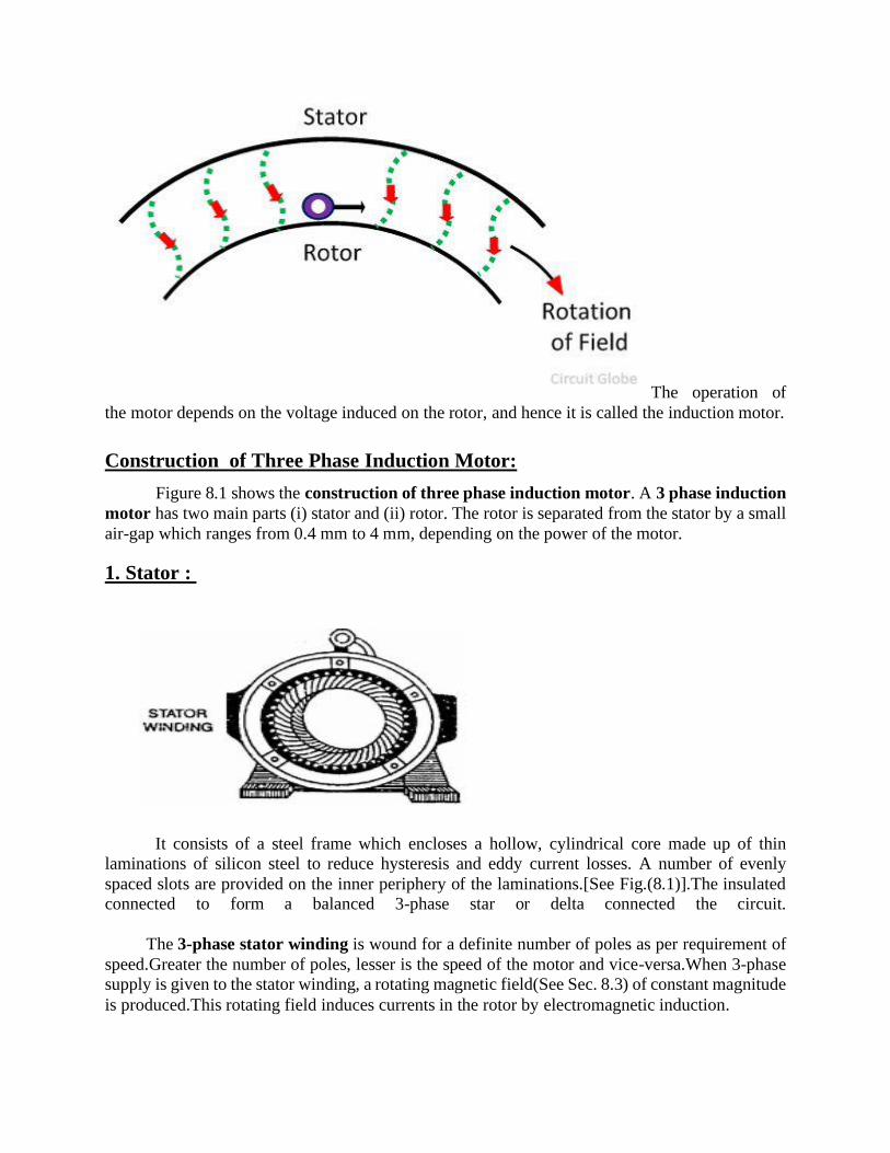
Working Principle of an Induction Motor:
The motor which works on the principle of electromagnetic induction is known as the induction
motor. The electromagnetic induction is the phenomenon in which the electromotive force induces
across the electrical conductor when it is placed in a rotating magnetic field.
The stator and rotor are two essential parts of the motor. The stator is the stationary part, and
it carries the overlapping windings while the rotor carries the main or field winding. The windings
of the stator are equally displaced from each other by an angle of 120°.
The induction motor is the single excited motor, i.e., the supply is applied only to the one part, i.e.,
stator. The term excitation means the process of inducing the magnetic field on the parts of the
motor.
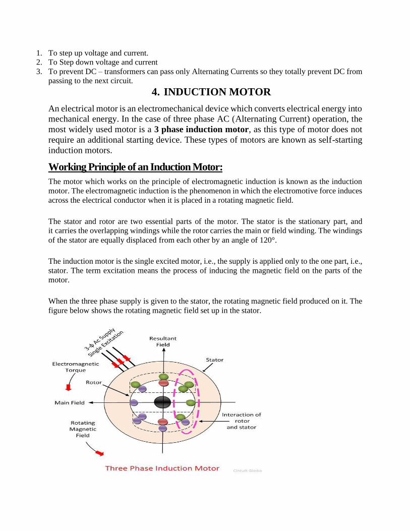
When the three phase supply is given to the stator, the rotating magnetic field produced on it. The
figure below shows the rotating magnetic field set up in the stator.
Page 20
In a DC motor, supply is needed to be given for the stator winding as well as the rotor winding.
But in an induction motor only the stator winding is fed with an AC supply.
▪ Alternating flux is produced around the stator winding due to AC supply. This alternating
flux revolves with synchronous speed. The revolving flux is called as "Rotating Magnetic
Field" (RMF).
▪ The relative speed between stator RMF and rotor conductors causes an induced emf in the
rotor conductors, according to the Faraday's law of electromagnetic induction. The rotor
conductors are short circuited, and hence rotor current is produced due to induced emf. That
is why such motors are called as induction motors.
(This action is same as that occurs in transformers, hence induction motors can be called
as rotating transformers.)
▪ Now, induced current in rotor will also produce alternating flux around it. This rotor flux
lags behind the stator flux. The direction of induced rotor current, according to Lenz's law,
is such that it will tend to oppose the cause of its production.
▪ As the cause of production of rotor current is the relative velocity between rotating stator flux
and the rotor, the rotor will try to catch up with the stator RMF. Thus the rotor rotates in the
same direction as that of stator flux to minimize the relative velocity. However, the rotor
never succeeds in catching up the synchronous speed. This is the basic working principle
of induction motor of either type, single phase of 3 phase.
▪
Why Rotor never runs at Synchronous Speed?
If the speed of the rotor is equal to the synchronous speed, no relative motion occurs between the
rotating magnetic field of the stator and the conductors of the rotor. Thus the EMF is not induced
on the conductor, and zero current develops on it. Without current, the torque is also not produced.
Because of the above mention reasons the rotor never rotates at the synchronous speed. The speed
of the rotor is always less than the speed of the rotating magnetic field.
Alternatively, the method of the working principle of Induction Motor can also be explained as
follows.
Let’s understand this by considering the single conductor on the stationary rotor. This conductor
cuts the rotating magnetic field of the stator. Consider that the rotating magnetic field rotates in
the clockwise direction. According to Faraday’s Law of electromagnetic induction, the EMF
induces in the conductor.
Page 21
As the rotor circuit is
completed by the external resistance or by end ring, the rotor induces an EMF which causes the
current in the circuit. The direction of the rotor induces current is opposite to that of the rotating
magnetic field. The rotor current induces the flux in the rotor. The direction of the rotor flux is
same as that of the current.
The interaction of rotor and stator fluxes
develops a force which acts on the conductors of the rotor. The force acts tangentially on the rotor
and hence induces a torque. The torque pushes the conductors of the rotor, and thus the rotor starts
moving in the direction of the rotating magnetic field. The rotor starts moving without any
additional excitation system and because of this reason the motor is called the self-starting motor.
Page 22
The operation of
the motor depends on the voltage induced on the rotor, and hence it is called the induction motor.
Construction of Three Phase Induction Motor:
Figure 8.1 shows the construction of three phase induction motor. A 3 phase induction
motor has two main parts (i) stator and (ii) rotor. The rotor is separated from the stator by a small
air-gap which ranges from 0.4 mm to 4 mm, depending on the power of the motor.
1. Stator :
It consists of a steel frame which encloses a hollow, cylindrical core made up of thin
laminations of silicon steel to reduce hysteresis and eddy current losses. A number of evenly
spaced slots are provided on the inner periphery of the laminations.[See Fig.(8.1)].The insulated
connected to form a balanced 3-phase star or delta connected the circuit.
The 3-phase stator winding is wound for a definite number of poles as per requirement of
speed.Greater the number of poles, lesser is the speed of the motor and vice-versa.When 3-phase
supply is given to the stator winding, a rotating magnetic field(See Sec. 8.3) of constant magnitude
is produced.This rotating field induces currents in the rotor by electromagnetic induction.
Page 23
2. Rotor:
The rotor, mounted on a shaft, is a hollow laminated core having slots on its outer periphery.The
winding placed in these slots (called rotor winding) may be one of the following two types:
(i) Squirrel cage type (ii) Wound type
(i) Squirrel cage rotor: It consists of a laminated cylindrical core having parallel slots on its
outer periphery.One copper or aluminum bar is placed in each slot.All these bars are joined at
each end by metal rings calledend rings.
This forms a permanently short circuited winding which is indestructible. The entire
construction (bars and end rings) resembles a squirrel cage and hence the name.The rotor is not
connected electrically to the supply but has current induced in it by transformer action from the
stator.
Those induction motors which employ squirrel cage rotor are called squirrel cage
induction motors.Most of 3 phase induction motors use squirrel cage rotor as it has a
remarkably simple and robust construction enabling it to operate in the most adverse
circumstances.
However, it suffers from the disadvantage of a low starting torque.It is because the rotor
bars are permanently short-circuited and it is not possible to add any external resistance to the
rotor circuit to have a large starting torque.
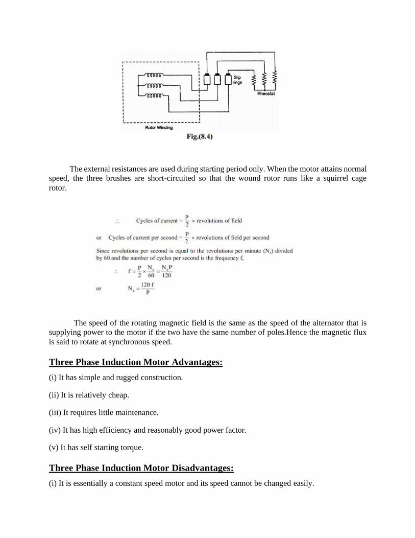
(ii) Wound rotor: It consists of a laminated cylindrical core and carries a 3-phase winding,
similar to the one on the stator [See Fig. (8.3)].The rotor winding is uniformly distributed in the
slots and is usually star-connected.The open ends of the rotor winding are brought out and joined
to three insulated slip rings mounted on the rotor shaft with one brush resting on each slip ring.
The three brushes are connected to a 3-phase star-connected rheostat as shown in Fig.
(8.4).At starting, the external resistances are included in the rotor circuit to give a large starting
torque.These resistances are gradually reduced to zero as the motor runs up to speed.
Page 24
The external resistances are used during starting period only. When the motor attains normal
speed, the three brushes are short-circuited so that the wound rotor runs like a squirrel cage
rotor.
The speed of the rotating magnetic field is the same as the speed of the alternator that is
supplying power to the motor if the two have the same number of poles.Hence the magnetic flux
is said to rotate at synchronous speed.
Three Phase Induction Motor Advantages:
(i) It has simple and rugged construction.
(ii) It is relatively cheap.
(iii) It requires little maintenance.
(iv) It has high efficiency and reasonably good power factor.
(v) It has self starting torque.
Three Phase Induction Motor Disadvantages:
(i) It is essentially a constant speed motor and its speed cannot be changed easily.
Page 25
(ii) Its starting torque is inferior to dc shunt motor.
Applications of Induction Motors:
• Wound rotor motors are suitable for loads requiring high starting torque and where a lower starting
current is required.
• The Wound rotor induction motors are also used for loads having high inertia, which results in
higher energy losses.
• Used for the loads which require a gradual buildup of torque.
• Used for the loads that require speed control.
• The wound rotor induction motors are used in conveyors, cranes, pumps, elevators and
compressors, fan.
• The maximum torque is above 200 percent of the full load value while the full load slip may be as
low as 3 percent. The efficiency is about 90 %.
5. SERVO MOTOR
A servo motor is an electrical device which can push or rotate an object with great precision. If
you want to rotate and object at some specific angles or distance, then you use servo motor. It is
just made up of simple motor which run through servo mechanism. If motor is used is DC
powered then it is called DC servo motor, and if it is AC powered motor then it is called AC servo
motor. We can get a very high torque servo motor in a small and light weight packages. Doe to
these features they are being used in many applications like toy car, RC helicopters and planes,
Robotics, Machine etc.
Construction of Servo Motor: Servo motor is Dc motor which consist of following parts
1. Stator winding
2. Rotor winding
3. Bearing
4. Shaft
5. Encoder
The servo motor consists of two winding stator and rotor winding. The stator winding is wound
on stationary part of the motor and this winding is also called field winding of the motor, this
winding could the permanent magnets. The rotor winding is wound on the rotating part of the
motor and this winding is also called the armature winding of the motor. The motor consists of
two bearing on front and back side for the free movement of shaft. Shaft is basically the iron rod
on which the armature winding is coupled. The encoder has the approximate sensor for telling the
rotational speed and revolution per minute of the motor.
Page 26
Working principle of Servo Motors:
• Servo motors is actually the dc motor and all dc motors work on the principle of Fleming
s left hand rule. This rule is used for determining the direction of force which act on the
DC motor armature conductor. This rule tells us if we extend our left hand,index finger,
middle finger and thumb in such a way that shown in figure 3
• Figure 3 Fleming s Left Hand Rule
• Then the index finger shows the magnetic field which is perpendicular to direction of
current, shows the middle finger in figure. When the current carrying conductor is placed
in magnetic field then the conductor experience a force in the direction, which is
perpendicular to the both direction of magnetic field and direction of current that is shows
by the thumb in figure 3
• The Servo Motor basically consists of a DC Motor, a Gear system, a position sensor and a
control circuit. The DC motors get powered from a battery and run at high speed and low
torque. The Gear and shaft assembly connected to the DC motors lower this speed into
sufficient speed and higher torque. The position sensor senses the position of the shaft from
its definite position and feeds the information to the control circuit. The control circuit
accordingly decodes the signals from the position sensor and compares the actual position
of the motors with the desired position and accordingly controls the direction of rotation
of the DC motor to get the required position. The Servo Motor generally requires DC
supply of 4.8V to 6 V.
• A servo consists of a Motor (DC or AC), a potentiometer, gear assembly and a controlling
circuit. First of all we use gear assembly to reduce RPM and to increase torque of motor.
Say at initial position of servo motor shaft, the position of the potentiometer knob is such
that there is no electrical signal generated at the output port of the potentiometer. Now an
electrical signal is given to another input terminal of the error detector amplifier. Now
difference between these two signals, one comes from potentiometer and another comes
from other source, will be processed in feedback mechanism and output will be provided
in term of error signal. This error signal acts as the input for motor and motor starts rotating.
Now motor shaft is connected with potentiometer and as motor rotates so the potentiometer
Page 27
and it will generate a signal. So as the potentiometer’s angular position changes, its output
feedback signal changes. After sometime the position of potentiometer reaches at a position
that the output of potentiometer is same as external signal provided. At this condition, there
will be no output signal from the amplifier to the motor input as there is no difference
between external applied signal and the signal generated at potentiometer, and in this
situation motor stops rotating.
Controlling Servo Motor:
All motors have three wires coming out of them. Out of which two will be used for Supply (positive
and negative) and one will be used for the signal that is to be sent from the MCU.
Servo motor is controlled by PWM (Pulse with Modulation) which is provided by the control
wires. There is a minimum pulse, a maximum pulse and a repetition rate. Servo motor can turn 90
degree from either direction form its neutral position. The servo motor expects to see a pulse every
20 milliseconds (ms) and the length of the pulse will determine how far the motor turns. For
example, a 1.5ms pulse will make the motor turn to the 90° position, such as if pulse is shorter
than 1.5ms shaft moves to 0° and if it is longer than 1.5ms than it will turn the servo to 180°.
Servo motor works on PWM (Pulse width modulation) principle, means its angle of rotation is
controlled by the duration of applied pulse to its Control PIN. Basically servo motor is made up
of DC motor which is controlled by a variable resistor (potentiometer) and some gears. High
speed force of DC motor is converted into torque by Gears. We know that WORK= FORCE X
DISTANCE, in DC motor Force is less and distance (speed) is high and in Servo, force is High
and distance is less. Potentiometer is connected to the output shaft of the Servo, to calculate the
angle and stop the DC motor on required angle.
Servo motor can be rotated from 0 to 180 degree, but it can go up to 210 degree, depending on the
manufacturing. This degree of rotation can be controlled by applying the Electrical Pulse of
proper width, to its Control pin. Servo checks the pulse in every 20 milliseconds. Pulse of 1 ms (1
Page 28
millisecond) width can rotate servo to 0 degree, 1.5ms can rotate to 90 degree (neutral position)
and 2 ms pulse can rotate it to 180 degree.
All servo motors work directly with your +5V supply rails but we have to be careful on the amount
of current the motor would consume, if you are planning to use more than two servo motors a
proper servo shield should be des
Advantages:
• If a heavy load is placed on the motor, the driver will increase the current to the motor coil as
it attempts to rotate the motor. Basically, there is no out-of-step condition.
• High-speed operation is possible.
Disadvantages:
• Since the servomotor tries to rotate according to the command pulses, but lags behind, it is not
suitable for precision control of rotation.
• Higher cost.
• When stopped, the motor’s rotor continues to move back and forth one pulse, so that it is not
suitable if you need to prevent vibration
•
Applications of Servo Motor:
1. It is used in robotic industry of position control.
2. It is used in robotic arms.
3. It is used in press and cutting industry for the cutting and pressing the piece precisely.
4. It is used in conveyer belt for start and stop the conveyer belt at every position.
5. It is used in digital cameras for auto focusing.
6. It is used in solar tracking system for tracking the sun at every precise moment of time.
7. It is used in labeling and packing industry for labels the monogram and packing the things
6.STEPPER MOTOR
Stepper Motor is a brushless electromechanical device which converts the train of electric pulses
applied at their excitation windings into precisely defined step-by-step mechanical shaft rotation.
The shaft of the motor rotates through a fixed angle for each discrete pulse. This rotation can be
linear or angular.It gets one step movement for a single pulse input.
When a train of pulses is applied, it gets turned through a certain angle. The angle through which
the stepper motor shaft turns for each pulse is referred as the step angle, which is generally
expressed in degrees.
Page 29
The number of input pulses given to the motor decides the step angle and hence the position of
motor shaft is controlled by controlling the number of pulses. This unique feature makes the
stepper motor to be well suitable for open-loop control system wherein the precise position of the
shaft is maintained with exact number of pulses without using a feedback sensor.
If the step angle is smaller, the greater will be the number of steps per revolutions and higher will
be the accuracy of the position obtained. The step angles can be as large as 90 degrees and as small
as 0.72 degrees, however, the commonly used step angles are 1.8 degrees, 2.5 degrees, 7.5 degrees
and 15 degrees.
The direction of the shaft rotation depends on the sequence of pulses applied to the stator. The
speed of the shaft or the average motor speed is directly proportional to the frequency (the rate of
input pulses) of input pulses being applied at excitation windings. Therefore, if the frequency is
low, the stepper motor rotates in steps and for high frequency, it continuously rotates like a DC
motor due to inertia.
Like all electric motors, it has stator and rotor. The rotor is the movable part which has no
windings, brushes and a commutator. Usually the rotors are either variable reluctance or permanent
magnet kind. The stator is often constructed with multipole and multiphase windings, usually of
three or four phase windings wound for a required number of poles decided by desired angular
displacement per input pulse.
Unlike other motors it operates on a programmed discrete control pulses that are applied to the
stator windings via an electronic drive. The rotation occurs due to the magnetic interaction
between poles of sequentially energized stator winding and poles of the rotor.
Page 30
Stepper motor working principle:
How does a stepper motor work? The stepper motor rotor is a permanent magnet, when the
current flows through the stator winding, the stator winding to produce a vector magnetic field.
The magnetic field drives the rotor to rotate by an angle so that the pair of magnetic fields of the
rotor and the magnetic field direction of the stator are consistent. When the stator's vector
magnetic field is rotated by an angle, the rotor also rotates with the magnetic field at an angle.
Each time an electrical pulse is input, the motor rotates one degree further. The angular
displacement it outputs is proportional to the number of pulses input and the speed is
proportional to the pulse frequency. Change the order of winding power, the motor will reverse.
Therefore, it can control the rotation of the stepping motor by controlling the number of pulses,
the frequency and the electrical sequence of each phase winding of the motor.
Page 31
Construction of a Stepper Motor:
There are several types of stepper motors are available in today’s market over a wide range of
sizes, step count, constructions, wiring, gearing, and other electrical characteristics. As these
motors are capable to operate in discrete nature, these are well suitable to interface with digital
control devices like computers.
Due to the precise control of speed, rotation, direction, and angular position, these are of particular
interest in industrial process control systems, CNC machines, robotics, manufacturing automation
systems, and instrumentation.
Types of Stepper Motors:
There are three basic categories of stepper motors, namely • Permanent Magnet Stepper Motor • Variable Reluctance Stepper Motor
• Hybrid Stepper Motor
In all these motors excitation windings are employed in stator where the number of windings
refer to the number of phases.
A DC voltage is applied as an excitation to the coils of windings and each winding terminal is
connected to the source through a solid state switch. Depends on the type of stepper motor, its
rotor design is constructed such as soft steel rotor with salient poles, cylindrical permanent
magnet rotor and permanent magnet with soft steel teeth. Let us discuss these types in detail.
Page 32
Variable Reluctance Stepper Motor:
It is the basic type of stepper motor that has been in existence for a long time and it ensures easiest
way to understand principle of operation from a structural point of view. As the name suggests,
the angular position of the rotor depends on the reluctance of the magnetic circuit formed between
the stator poles (teeth) and rotor teeth.
Variable Reluctance Stepper Motor
Construction of Variable Reluctance Stepper Motor:
It consists of a wound stator and a soft iron multi-tooth rotor. The stator has a stack of silicon steel
laminations on which stator windings are wound. Usually, it is wound for three phases which are
distributed between the pole pairs.
The number of poles on stator thus formed is equal to an even multiple of the number of phases
for which windings are wounded on stator. In the figure below, the stator has 12 equally spaced
projecting poles where each pole is wound with an exciting coil. These three phases are energized
from of a DC source with the help of solid state switches.
The rotor carries no windings and is of salient pole type made entirely of slotted steel laminations.
The rotor pole’s projected teeth have the same width as that of stator teeth. The number of poles
on stator differs to that of rotor poles, which provides the ability to self start and bidirectional
rotation of the motor.
Page 33
The relation of rotor poles in terms of stator poles for a three phase stepper motor is given as, Nr
= Ns ± (Ns / q). Here Ns = 12, and q= 3, and hence Nr = 12 ± (12 / 3) = 16 or 8. An 8-pole
construction rotor without any excitation is illustrated below.
Construction of Variable Reluctance Stepper Motor
Working of Variable Reluctance Stepper Motor:
The stepper motor works on the principle that the rotor aligns in a particular position with the teeth
of the excitation pole in a magnetic circuit wherein minimum reluctance path exist. Whenever
power is applied to the motor and by exciting a particular winding, it produces its magnetic field
and develops its own magnetic poles.
Due to the residual magnetism in the rotor magnet poles, it will cause the rotor to move in such a
position so as to achieve minimum reluctance position and hence one set of poles of rotor aligns
with the energized set of poles of the stator. At this position, the axis of the stator magnetic field
matches with the axis passing through any two magnetic poles of the rotor.
When the rotor aligns with stator poles, it has enough magnetic force to hold the shaft from moving
to the next position, either in clockwise or counter clockwise direction.
Consider the schematic diagram of a 3-phase, 6 stator poles and 4 rotor teeth is shown in figure
below. When the phase A-A’ is supplied with a DC supply by closing the switch -1, the winding
become a magnet which results one tooth become North and other South. So the stator magnetic
axis lies along these poles.
Due to the force of attraction, stator coil North Pole attracts nearest rotor tooth of opposite polarity,
i.e., South and South Pole attract nearest rotor tooth of opposite polarity, i.e., North. The rotor
then adjusts to its minimum reluctance position where the rotor magnetic axis exactly matches
with stator magnetic axis.
Page 34
Working of Variable Reluctance Stepper Motor
When the phase B-B’ is energized by closing switch -2 keeping phase A-A’ remain de-energized
by opening switch-1, winding B-B’ will produce the magnetic flux and hence the stator magnetic
axis shifts along the poles thus formed by it. Hence the rotor shifts to the least reluctance with
magnetized stator teeth and rotates through an angle of 30 degrees in the clockwise direction.
When the switch-3 is energized after opening switch-2, the phase C-C’ is energized, the rotor teeth
align with new position by moving through an additional angle of 30 degrees. By this way, the
rotor moves clockwise or counterclockwise direction by successively exciting stator windings in
a particular sequence. The step angle of this 3-phase 4-pole rotor teeth stepper motor is expressed
as, 360/ (4 × 3) = 30 degrees (as step angle = 360 / Nr × q).
The step angle can be further reduced by increasing the number of poles on the stator and rotor, in
such case motors are often wound with additional phase windings. This can also be achieved by a
adopting different construction of stepper motors such as multistack arrangement and reduction
gear mechanism.
Permanent Magnet Stepper Motor:
The permanent magnet design motor is perhaps the most common among several types of stepper
motors. As the name implies, it adds permanent magnets to the motor construction. This type of
stepper motors is also referred as can-stack motor or tin-can motor. The main advantage of this
motor is its low manufacturing cost. This type of motor has 48-24 steps per revolution.
Permanent Magnet Stepper Motor
Page 35
Construction Permanent Magnet Stepper Motor:
In this motor, the stator is of multipolar and its construction is similar to that of variable reluctance
stepper motor as discussed above. It consists of slotted periphery on which stator coils are wound.
It has projected poles on the slotted structure where the wound windings can be two or three or
four-phase.
The end terminals of all these windings are bought out and connected to the DC excitation via
solid state switches in the drive circuit.
Construction Permanent Magnet Stepper Motor
The rotor is made up of a permanent magnet material like a ferrite that can be in the shape of either
cylindrical or salient pole, but usually it is of smooth cylindrical type. The rotor designed to have
an even number of permanent magnetic poles with alternate North and South polarities.
Working of Permanent Magnet Stepper Motor:
The operation of this motor works on the principle that unlike poles attract each other and like
poles repel each other. When the stator windings are excited with a DC supply, it
produces magnetic flux and establishes the North and South poles. Due to the force of attraction
and repulsion between permanent magnet rotor poles and stator poles, the rotor starts moving up
to the position for which pulses are given to the stator.
Consider a 2-phase stepper motor with two permanent magnetic rotor poles as shown in the figure
below.
Page 36
Working of Permanent Magnet Stepper Motor:
When the phase A is energized with a positive with respect to the A’, the windings establish North
and South poles. Due to the force of attraction, the rotor poles align with stator poles such that the
magnetic pole axis of rotor adjusts with that of stator as shown in figure.
When the excitation is switched to B phase and switching off phase A, the rotor further adjusts to
magnetic axis of phase B, and thus rotates through 90 degrees in clockwise direction.
Next, if the phase A is energized with a negative current with respect to A’, the formation of stator
poles causes the rotor to move through another 90 degrees in clockwise direction.
In the same way, if the phase B is excited with negative current by closing phase A switch, the
rotor rotates through another 90 degrees in the same direction. Next, if the phase A is excited with
positive current, the rotor comes to the original position thus making a 360 degrees complete
revolution. This implies that, whenever the stator is excited, the rotor tends to rotate through 90
degrees in clockwise direction.
The step angle of this 2-phase 2-pole permanent magnet rotor motor is expressed as, 360/ (2 × 2)
= 90 degrees. The step size can be reduced by energizing two phases simultaneously or a sequence
of 1-phase ON and 2-phase ON modes with a proper polarity.
Hybrid Stepper Motor:
It is the most popular type of stepper motor as it provides better performance than permanent
magnet rotor in terms of step resolution, holding torque and speed. However, these motors are
more expensive than PM stepper motors. It combines the best features of both variable reluctance
Page 37
and permanent magnet stepper motors. These motors are used in applications that require very
small stepping angle such as 1.5, 1.8 and 2.5 degrees.
Hybrid Stepper Motor
Construction of Hybrid Stepper Motor:
The stator of this motor is same as its permanent magnet or reluctance type counterpart. The stator
coils are wound on alternate poles. In this, the coils of different phases are wound on each pole,
usually two coils at a pole which is referred as a bifilar connection.
The rotor consists of a permanent magnet which is magnetized in axial direction to create a pair of
magnetic poles (N and S poles). Each pole is covered with uniformly spaced teeth. The teeth are
made up of soft steel and two section, of which on each pole are misaligned each other by a half-
tooth pitch.
Working of Hybrid Stepper Motor:
This motor works similar to that of permanent magnet stepper motor. The figure above shows 2-
phase, 4-pole, 6-tooth rotor hybrid stepper motor. When the phase A-A’ is excited with a DC
supply, keeping B-B’ unexcited, the rotor aligns such that the south pole of the rotor faces north
pole of the stator while north pole of rotor faces south pole of the stator.
Working of Hybrid Stepper Motor
Now, if the phase B-B’ is excited, keeping A-A’ switched off in such a way that upper pole
becomes north and lower becomes south, then the rotor will align to a new position by moving
Page 38
through counterclockwise direction. If the phase B-B’ is oppositely excited such that the upper
pole becomes south and lower becomes north, then the rotor will turn clockwise direction.
By a proper sequence of pulses to the stator, the motor will turn in desired direction. For every
excitation, rotor will get locked into new position, and even if excitation is removed motor still
maintains its locked condition due to the permanent magnet excitation. The step angle of this 2-
phase, 4-pole, 6-tooth rotor motor is given as 360/ (2 × 6) = 30 degrees. In practice, hybrid motors
are constructed with more number of rotor poles in order to get high angular resolution.
motor in half stepping is given below.
Advantages of Stepper Motor:
• At standstill position, the motor has full torque. No matter if there is no moment or changing
position.
• It has a good response to starting, stopping and reversing position.
• As there is no contact brushes in the stepper motor, It is reliable and the life expectancy depends
on the bearings of the motor.
• The motor rotation angle is directly proportional to the input signals.
• It is simple and less costly to control as motor provides open loop control when responding to
the digital input signals.
• The motor speed is directly proportional to the input pulses frequency, this way a wide range
of rotational speed can be achieved.
• When load is coupled to the shaft, it is still possible to realize the synchronous rotation with
low speed.
Page 39
• The exact positioning and repeatability of movement is good as it has a 3-5% accuracy of a step
where the error is non cumulative from one step to another.
• Stepper motors are safer and low cost (as compared to servo motors), having high torque at low
speeds, high reliability with simple construction which operates at any environment.
Disadvantages of Stepper Motors:
• Stepper motors having low Efficiency.
• It has low Accuracy.
• Its torque declines very quickly with speed.
• As stepper motor operates in open loop control, there is no feedback to indicate potential missed
steps.
• It has low torque to inertia ratio means it can’t accelerate the load very quickly.
• They are noisy.
Applications of Stepper Motors:
• Stepper motors are used in automated production equipment and automotive gauges and
industrial machines like packaging, labeling, filling and cutting etc.
• It is widely used in security devices such as security & surveillance cameras.
• In medical industry, stepper motors are widely used in samples, digital dental photography,
respirators, fluid pumps, blood analysis machinery and medical scanners etc.
• They are used in consumer electronics in image scanners, photo copier and printing machines
and in digital camera for automatic zoom and focus functions and positions.
• Stepper motors also used in elevators, conveyor belts and lane diverters.