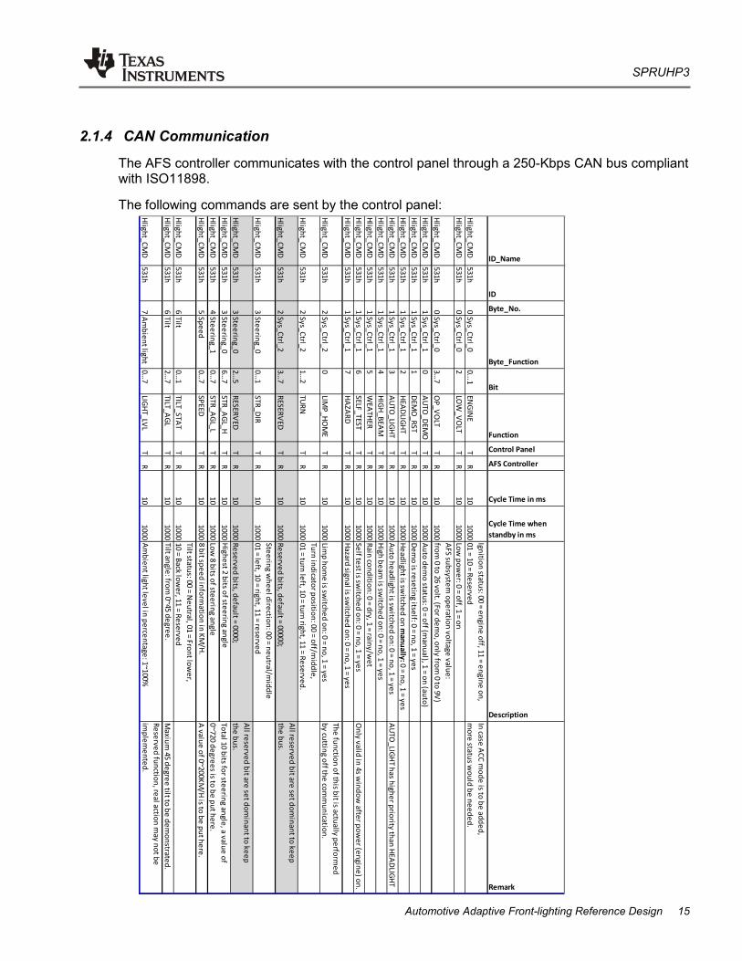
Reference Design SPRUHP3 – July 2013 1 Automotive Adaptive Front-lighting System Reference Design Renton Ma System Application Engineering/MCU ABSTRACT The Adaptive Front-lighting System (AFS) is one part of the active safety system of a middle-high end passenger car, providing an optimized vision to the driver during night time and other poor-sight conditions of the road by adapting the headlight angle and intensity, and judging the speed of the car, the steering wheel angle, the weather condition, and yaw and tilt rate of the car. To facilitate a user’s development of such a system and to demonstrate the performance of TI’s automotive MCU family, a reference design of AFS is developed. This article describes the functions of the reference design, as well as the implementation. Furthermore, it states the guidelines for manipulating the demonstration of the reference design.
Transcript
Reference Design SPRUHP3 – July 2013
1
Automotive Adaptive Front-lighting System Reference Design
Renton Ma System Application Engineering/MCU
ABSTRACT
The Adaptive Front-lighting System (AFS) is one part of the active safety system of a middle-high end passenger car, providing an optimized vision to the driver during night time and other poor-sight conditions of the road by adapting the headlight angle and intensity, and judging the speed of the car, the steering wheel angle, the weather condition, and yaw and tilt rate of the car.
To facilitate a user’s development of such a system and to demonstrate the performance of TI’s automotive MCU family, a reference design of AFS is developed.
This article describes the functions of the reference design, as well as the implementation. Furthermore, it states the guidelines for manipulating the demonstration of the reference design.
SPRUHP3
2 Automotive Adaptive Front-lighting System Reference Design
Contents 1 Functions of Adaptive Front-lighting System ............................................................................ 3
1.1 Major Functions ...................................................................................................................... 3 1.2 Functions of the Reference Design ......................................................................................... 4 1.3 System Architecture................................................................................................................ 5 1.4 AFS Controller ........................................................................................................................ 7 1.5 AFS Slave .............................................................................................................................. 7 1.6 Control Panel .......................................................................................................................... 8
2 Implementation of the Reference Design ................................................................................... 8 2.1 Implementation of the AFS Controller ..................................................................................... 8
2.1.1 Power Supply .............................................................................................................. 8 2.1.2 Operation Modes ...................................................................................................... 10 2.1.3 Light Modes .............................................................................................................. 12 2.1.4 CAN Communication ................................................................................................. 15 2.1.5 Driving the Lamps With PWM (HET) ......................................................................... 17
2.2 Implementation of the AFS Slave.......................................................................................... 18 2.2.1 Stepper Motor Control ............................................................................................... 18 2.2.2 LIN Communication ................................................................................................... 22
3 Operation of the Demo Set ........................................................................................................ 23 3.1.1 Connections .............................................................................................................. 23 3.1.2 Operation of the Control Panel .................................................................................. 26 3.1.3 Starting the Demo ..................................................................................................... 31
1 Functions of Adaptive Front-lighting System An adaptive front-lighting system is defined as in ECE324-R123 as “a lighting device, providing beams with differing characteristics for automatic adaptation to varying conditions of use of the dipped-beam (passing beam) and, if it applies, the main-beam (driving-beam) with a minimum functional content; such systems consist of the "system control", one or more "supply and operating device(s)", if any, and the "installation units" of the right and of the left side of the vehicle” (refer to ECE324, Addendum 122: Regulation No. 123).
1.1 Major Functions
Basically, an AFS provides the following functions:
• Town passing beam (Class V)
• Basic/Country passing beam (Class C)
• Motorway passing beam (Class E)
• Wet-road passing beam (Class W)
• Static cornering light
• Dynamic swivel/level lighting
Town passing beam (Class V): At speeds below 50 km/h, town light provides a wider light distribution at reduced range, helping drivers to more clearly see pedestrians on the edge of the road.
Basic/Country passing beam (Class C): The basic light illuminates the left- and right-hand edges of the road more brightly and widely than the conventional low beam. It is usually activated at speeds between 50 and 100 km/h.
Motorway passing beam (Class E): Motorway light improves vision on highways and expressways. From 100 km/h, this beam illuminates the roadway significantly further ahead and focuses more on the left-hand edge of the road. The motorway light switches on automatically at speeds greater than 100 km/h.
Wet-road passing beam (Class W): This beam is activated when the rain sensor detects precipitation or the windshield wipers are on for 2 minutes or more. The edges of the road are more strongly illuminated for better orientation to the guiding lines.
SPRUHP3
4 Automotive Adaptive Front-lighting System Reference Design
Figure 1. Light Modes Static cornering light: Static cornering light helps during maneuvers in dark access roads. At speeds of up to 40 km/h, one additional cornering light comes on when the indicator is actuated or the steering wheel turned through about 90 degrees to the right or left. Dynamic swiveling and leveling: • Leveling: The AFS adjusts the direction of the headlight (projector) vertically according to the
front and rear chassis height sensors. Adjusting the pitch angle of the headlight according to static vehicle load transfer (occupant numbers, luggage) is called static leveling, while adjusting headlight pitch angle according to dynamic vehicle load transfer (acceleration, deceleration) is known as dynamic leveling.
• Swiveling: The AFS swivels the headlights horizontally by judging the input from the steering angle sensor and the speed of the car. The system provides a curve rate at up to 15 degrees; obstacles become more easily visible.
1.2 Functions of the Reference Design
The reference design of the AFS provides the light mode switching functions as mentioned previously. This is done by judging the vehicle speed sent through the CAN bus. All four classes of light modes are supported by the reference design.
By checking the light mode, vehicle speed as well as the steering wheel position, the reference design provides the static cornering light function. With the information of the steering wheel and the tilt level of the car through the CAN bus, the reference design can also perform leveling and swiveling of the passing beam.
In addition, the turning indicator, parking light, and high beam are also implemented in the reference design for a better demonstration.
This design considers the general automotive operation conditions like electrical disturbances (ISO7637), environmental conditions (ISO16750), and other existing industrial standards. To better demonstrate the functions of the reference design, a demonstration set is also built with an automotive headlight product as the target load. To generate command signals as car speed, steering angle, and so on, a control panel is built for this demonstration set.
1.3 System Architecture
Figure 2 shows the AFS in an automotive network structure.
Figure 2. Automotive Network Structure
This is a concept structure of the network connection for all components in the vehicle that are concerned in the AFS.
Sensors in different positions around the vehicle are connected to BCM through the CAN or LIN bus. Front and rear chassis sensors detect the height of the vehicle and are connected through the LIN to BCM or through HS-CAN to the chassis system. In the latter case, information about the height of the vehicle is transferred to BCM through a CAN bus gateway unit.
Rain sensors are usually implemented in the wiper or washer subsystem of the body or comfort system. This subsystem is then connected to an intelligent wiper controller through the LIN, and the wiper controller sends the weather condition information back to BCM through LS-CAN as the body or comfort system; or it is connected directly with the BCM through the LIN bus as shown in Figure 2.
Vehicle speed sensor is usually located and connected in the power train system of a car through HS-CAN. The steering angle sensor is likely connected with the EPS, and the ESP subsystem belongs to the chassis system through HS-CAN. Here, their connections are simplified to a direct connection to BCM through HS-CAN.
SPRUHP3
6 Automotive Adaptive Front-lighting System Reference Design
The AFS controller receives the significant sensor information from BCM through LS-CAN of the body system or HS-CAN of the chassis system. After processing on these sensor inputs, the AFS controller sends commands through the LIN bus to the AFS slave and the HID slave to perform the operation on both left and right headlights.
Figure 3 shows the system architecture of the reference design.
Figure 3. System Architecture of the Reference Design
The following three modules are implemented:
• Control panel (for demo)
• AFS controller
• AFS slave
The control panel provides interface to the demonstrator/user with buttons, switches, and displays. The control panel collects the commands of input and transfers them into pseudo sensor signals. These signals are sent to the AFS controller through HS-CAN.
The AFS controller acts as the central controller of the light. It receives and analyzes the sensor signals from the CAN bus, and make the judgment to determine the movement and light intensity of the headlight. The AFS controller sends commands through the LIN to the AFS slave for lamp movement and turns on and off all the lamps in the headlight.
The AFS slave controls the stepper motors equipped with the headlight projector and achieves the movement of the light according to the commands sent by the AFS controller.
The AFS controller is the main control unit of the system. In the reference design, the AFS controller performs the following operations:
• Checks and sets the operation mode of the entire system
• Switches the light mode according to the vehicle speed and steering wheel position
• Communicates with the host through the CAN bus
• Sends commands to both the AFS slaves on the left and right headlights through the LIN bus to adjust the position of the lamp
• Drives the parking light, HID, high beam, cornering light, and the turn indicator for demonstration purpose
A TMS470MF03107 MCU is implemented on the AFS controller to achieve the expected performance. This MCU belongs to the TI Hercules MCU family.
The TMS470M safety microcontroller family is based on the widely adopted ARM® Cortex™-M3 CPU running at 80 MHz. This family offers several flash memory and RAM options and a wide range of connectivity and control peripherals, such as CAN, LIN and high-end timer (HET) for PWM generation. Built-in safety features like CPU and RAM self-test (BIST) engines, ECC, and parity checking enable the TMS470M device to support applications that meet the IEC61508 safety standard. The TMS470M safety microcontrollers are AEC-Q100-qualified and are the correct fit for safety and transportation applications with lower performance needs.
The TMS470MF03107 MCU has 256KB of code flash and 64KB of data flash for EEPROM emulation (320KB of flash in total), and a 100-pin QFP package.
1.5 AFS Slave
ECE324-R123 mentions that any combination of moving the lamp or light source array can be implemented to achieve an adaptive front light. In this reference design, movement of the HID projector is used to perform the passing beam adaption.
The movement of the lamp is performed by the AFS slave in the system by controlling two stepper motors equipped in the headlight. In a practical automotive system, there is one such control unit on both the right and left headlight units.
An MSP430F2272 device is implemented on the AFS slave to control the stepper motors. This device is equipped with a 16-bit high-performance CPU core with 32KB of flash, which is sufficient for controlling the motor and communication with the LIN master.
The MSP430F2272 device is also chosen because it is a very small 40-pin, QFN package UART module with LIN support and ultra-low power consumption.
SPRUHP3
8 Automotive Adaptive Front-lighting System Reference Design
1.6 Control Panel
For better demonstration, a control panel with buttons and switches as well as display is built with the reference design. The functions of the control panel are explained in the operation guide section.
2 Implementation of the Reference Design
2.1 Implementation of the AFS Controller
Figure 4 shows the control board of the AFS controller.
Figure 4. Control Board of the AFS Controller
The following sections explain the major design and implementation considerations of the AFS controller.
2.1.1 Power Supply
There are several requirements for power supply circuit in the automotive applications requested by ISO7637-2 and ISO16750-2. The most important requirements are reverse battery polarity protection, momentary supply drop, and load dump voltage protection.
For reverse battery polarity protection, a power MOSFET is implemented in our reference solution to provide lower power loss than a serial diode during normal operation mode and better endurance during reverse battery mode, as shown in Figure 5.
Figure 5. Power Supply Circuit of the AFS Controller
Because the AFS controller in this reference design must drive several lamps as its load with roughly a 30-A maximum current, a power MOSFET with a relatively larger current driving capability is chosen here. To reduce cost, an N-channel power MOSFET is chosen and implemented into the circuit on the ground line for easier circuit design.
As for the momentary power supply drop, two pieces of 330-µF capacitors are added to the power circuit to improve the power-saving capability.
Load dump voltage is a common concern in automotive applications. Load dump voltage occurs if a discharged battery is disconnected when the alternator is generating charging current and other loads remain on the alternator circuit.
Usually, car makers implement suppressors in the alternator side so that the load dump is suppressed to 45 V, as mentioned by ISO7637-2.
To survive the load dump voltage, a TLE4275 12- to 5-V LDO is used in this reference solution.
TI’s TLE4275 LDO provides the capability to sustain a load dump voltage of up to 45 V in an automotive application, thus making the design of the power supply circuit much easier.
Figure 6 shows the connection of the TLE4275 LDO in the schematic of the reference solution.
SPRUHP3
10 Automotive Adaptive Front-lighting System Reference Design
Figure 6. TLE4275 Schematic
CAUTION:
When RESET output of the TLE4275 LDO is to be used by TMS470MF03107, populate R144 and R146 and unpopulate R145. When RESET is not used by the MCU, populate R145 and unpopulate R144 and R146. Do not populate R144/R146 and R145 at same time.
2.1.2 Operation Modes
The AFS controller works in different operation modes, depending on the command through the CAN bus and the error status.
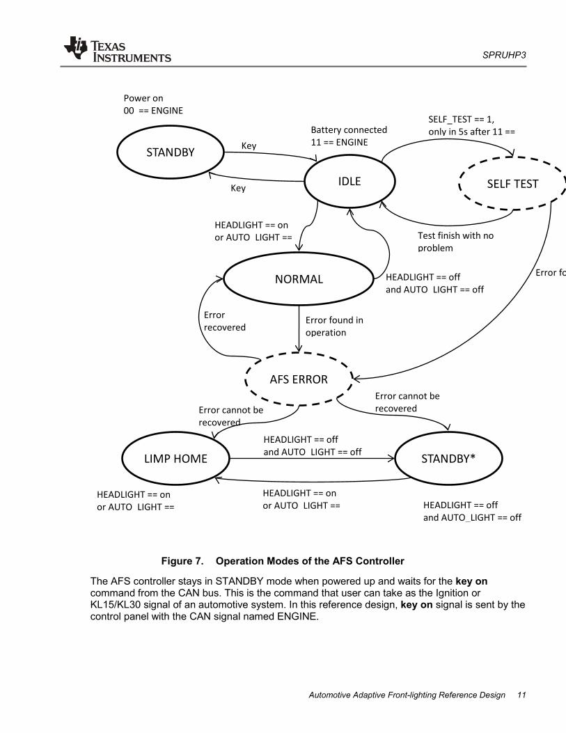
The AFS controller stays in STANDBY mode when powered up and waits for the key on command from the CAN bus. This is the command that user can take as the Ignition or KL15/KL30 signal of an automotive system. In this reference design, key on signal is sent by the control panel with the CAN signal named ENGINE.
IDLE
STANDBY
NORMAL
SELF TEST
AFS ERROR
LIMP HOME STANDBY*
Power on 00 == ENGINE
Battery connected 11 == ENGINE
SELF_TEST == 1, only in 5s after 11 ==
Test finish with no problem
Error fo
HEADLIGHT == on or AUTO_LIGHT ==
Error found in operation
HEADLIGHT == on or AUTO_LIGHT ==
Error cannot be recovered
Error recovered
HEADLIGHT == off and AUTO_LIGHT == off
Error cannot be recovered
Key
Key
HEADLIGHT == off and AUTO_LIGHT == off
HEADLIGHT == off and AUTO_LIGHT == off
HEADLIGHT == on or AUTO_LIGHT ==
SPRUHP3
12 Automotive Adaptive Front-lighting System Reference Design
In STANDBY mode, only CAN communication is monitored. None of the lighting operation is functional. The user can set the controller to lower power mode, which is not implemented for demonstration.
When the key on command is received, the AFS controller enters IDLE mode. In this mode, the AFS controller turns on the parking light to indicate its operation mode and waits for headlight operation commands. The AFS controller responds to the turning command and the hazard command in IDLE mode and flashes the indicator.
Either the HEADLIGHT on (low beam or high beam) command or the AUTO_LIGHT on command can trigger the mode switch from IDLE to NORMAL operation mode.
In NORMAL operation mode, the parking light is turned off. Low beam is on according to the status of the HEADLIGHT command. If the AUTO_LIGHT command is off, then low beam is always on in NORMAL operation mode. The high beam can be triggered by the high beam command.
In this operation mode, the AFS controller checks the information on the CAN bus and determines the light mode. It sends commands to the slave through the LIN bus to perform proper movement of the lamp.
If the headlight is switched off, both HEAD_LIGHT and AUTO_LIGHT are off, AFS controller goes back to IDLE mode.
The AFS controller can be set to SELF TEST mode when the system first time enters IDLE, and the SELF TEST command is received within 5 seconds after IDLE mode is entered.
In SELF TEST mode, the AFS controller orders the lamps to turn on and off in sequence and moves the lamp to check whether there is a problem of the headlight components.
This procedure lasts for approximately 5 seconds, and the AFS controller returns to IDLE mode.
NOTE: SELF TEST mode can be entered only once in the normal operation procedure. SELF TEST mode can be entered multiple times only when AUTO DEMO is activated for demonstration purpose.
AFS ERROR mode is entered whenever an error is detected in the system. The AFS controller tries to recover the error and return to the previous operation mode. If the error cannot be recovered, the AFS controller enters either LIMP HOME mode or STANDBY mode.
LIMP HOME mode provides the fundamental lighting function without any movement of the lamp. The AFS controller tries to restore the position of the projector and always turn it on. This occurs mainly when force limp home signal is received or CAN communication is lost for a certain period of time (typically, 5 seconds).
2.1.3 Light Modes
Lighting mode is decided by the AFS controller according to vehicle speed and weather conditions.
At speeds of less than 50 km/h, town light provides a wider light distribution at reduced range, thus helping drivers more clearly see pedestrians on the edge of the road. The headlight is swiveled left and right to provide larger sight range. The headlight is swiveled for an 8-degree angle toward each side.
No dynamic swiveling is to be performed in this lighting mode.
Leveling is performed in this lighting mode.
Basic/Country passing beam (Class C): The basic light illuminates the left- and right-hand edges of the road more brightly and widely than does the conventional low beam. The basic light is activated at speeds between 50 and 100 km/h. To activate the light mode, vehicle speed must be kept in this range for at least 5 seconds. (The user can set the time according to application; for demonstration purposes, this value is set to 5 seconds.)
The headlight keeps a straight position of the neutral position axis (Δφ = 0°) and swivels according to the steering angle of the vehicle within the range of αmax and γmax (see Figure 8).
Figure 8. Horizontal lighting range
Leveling is performed in this lighting mode.
α γ
αmax
γmax
αmax
= 20°, γmax
= 10°
SPRUHP3
14 Automotive Adaptive Front-lighting System Reference Design
Motorway passing beam (Class E):
Motorway light improves vision on highways and expressways: from a speed of 100 km/h, motorway light illuminates the roadway significantly further ahead and focuses more on the left-hand edge of the road. Vehicle speed must be kept in this range for at least 5 seconds to activate the light mode. (The user can set the time according to application; for demonstration purposes, this value is set to 5 seconds.)
The headlight keeps a straight position of the neutral position axis (Δφ = 0°) and swivels according to the steering angle of the vehicle within the range of αmax and γmax.
Leveling is performed in this lighting mode.
Wet-road passing beam (Class W):
This beam is activated when the rain sensor detects precipitation or the windshield wipers are on for 2 seconds or more in basic passing beam (Class C) mode and motorway passing beam (Class E) lighting mode. The edges of the road are more strongly illuminated for better orientation to the guiding lines. The light cone is somewhat shorter on the left-hand side, moderating light reflection on the wet, reflective road surface.
The neutral position axis of the headlight is swiveled for an angle of Δφ (5 degrees) toward each side, as shown in Figure 9. Horizontal swivel range is also changed based on the axis shift by Δφ (5 degrees).
Leveling is performed in this lighting mode.
An additional 2 degrees downward of the headlight is applied in this mode.
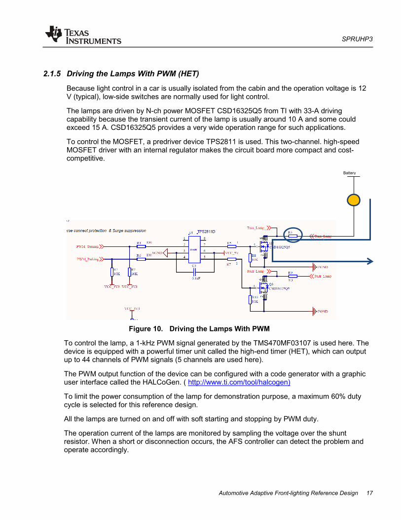
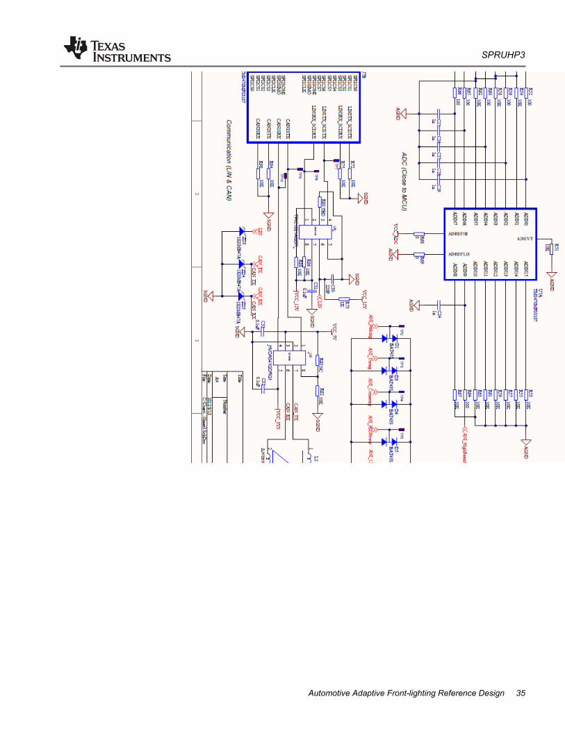
Because light control in a car is usually isolated from the cabin and the operation voltage is 12 V (typical), low-side switches are normally used for light control.
The lamps are driven by N-ch power MOSFET CSD16325Q5 from TI with 33-A driving capability because the transient current of the lamp is usually around 10 A and some could exceed 15 A. CSD16325Q5 provides a very wide operation range for such applications.
To control the MOSFET, a predriver device TPS2811 is used. This two-channel. high-speed MOSFET driver with an internal regulator makes the circuit board more compact and cost-competitive.
Figure 10. Driving the Lamps With PWM
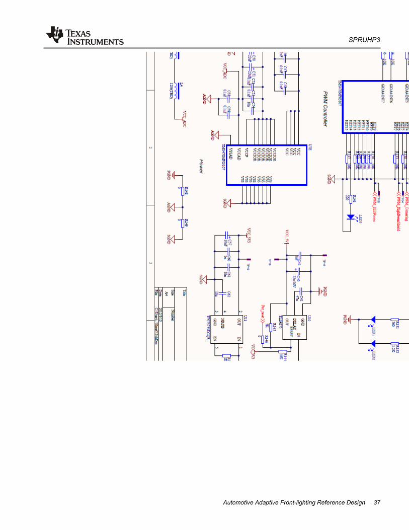
To control the lamp, a 1-kHz PWM signal generated by the TMS470MF03107 is used here. The device is equipped with a powerful timer unit called the high-end timer (HET), which can output up to 44 channels of PWM signals (5 channels are used here).
The PWM output function of the device can be configured with a code generator with a graphic user interface called the HALCoGen. ( http://www.ti.com/tool/halcogen)
To limit the power consumption of the lamp for demonstration purpose, a maximum 60% duty cycle is selected for this reference design.
All the lamps are turned on and off with soft starting and stopping by PWM duty.
The operation current of the lamps are monitored by sampling the voltage over the shunt resistor. When a short or disconnection occurs, the AFS controller can detect the problem and operate accordingly.
18 Automotive Adaptive Front-lighting System Reference Design
2.2 Implementation of the AFS Slave
Figure 11 shows the control board of the AFS slave.
s
Figure 11. Control Board of the AFS Slave
The following sections explain the major design and implementation considerations of the AFS slave.
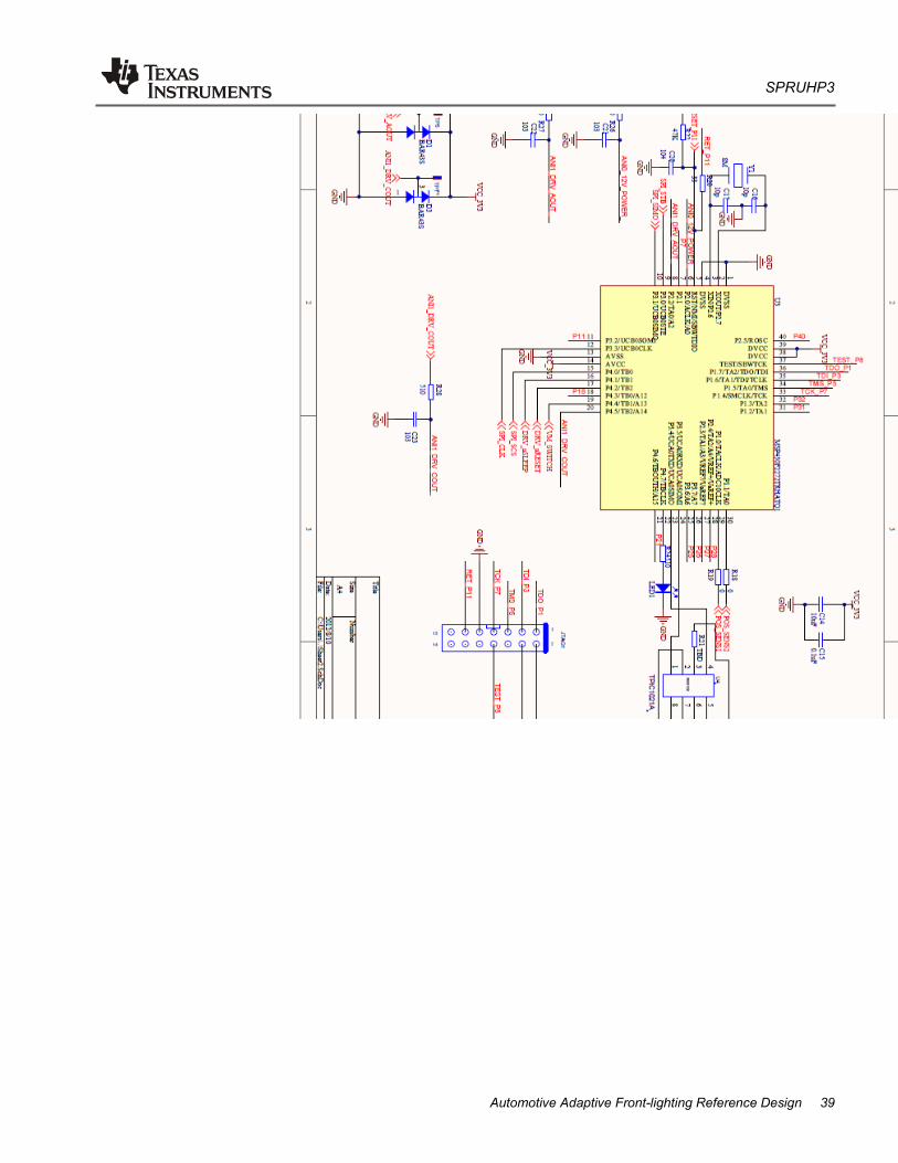
2.2.1 Stepper Motor Control
In most of the AFSs, stepper motors are used to move the position of the projector. In this reference design, two stepper motors are used: one for vertical movement and the other for horizontal movement.
The stepper motor for vertical movement is a 24-step linear stepper motor with12-V operation voltage and 1-A driving current. The stepper motor for horizontal movement is a 24-step permanent magnetic motor, also with 12-V operation voltage and 1-A driving current.
To drive these motors, a 4-bridge serial interface motor driver from TI, DRV8823, is used.
The DRV8823 driver provides the capability to drive two bipolar stepper motors at the same time with up to 1.5-A current on each winding, eight current levels for microstepping, selectable slow or mixed decay mode, and has internal reference for 3.3 V.
The previously mentioned features of the DRV8823 driver make it the correct device for this reference design.
Figure 12 shows the connection of the DRV8823 in the AFS slave system.
Figure 12. DRV8823 Driver Schematic
With the DRV8823 driver, the user can easily perform 8-step microstepping to control both stepper motors.
SPRUHP3
20 Automotive Adaptive Front-lighting System Reference Design
Because the DRV8823 driver operates based on the commands it receives from the SPI interface, the MCU must update the chopping current ratio to achieve the stepping.
Table 1 lists the available chopping current ratio provided by the DRV8823 driver.
Because PM motors have self-inductance, proper decay of the current must be applied to the driving method. In an AFS slave application, slow decay is performed in charging phases, and mixed decay is performed for the discharge phases to make the rotation smooth. See Figure 13.
The serial command to be sent to the DRV8823 driver is organized in the following code:
22 Automotive Adaptive Front-lighting System Reference Design
2.2.2 LIN Communication
The AFS slave communicates with the AFS controller through a LIN bus as a slave node with a 20-Kbps baud rate following the LIN2.0 protocol specification.
The LIN communication commands are as follows:
ID(h
ex w
ithou
t Pa
rity) ID
(dec
with
out
Parit
y)
ID-F
ield
(h
ex w
ith P
arity
)ID
7 ..
ID0
leng
th o
f m
essa
ge (B
yte) frame-name
Byt
e-N
r. Bit Function Remark
0x30 48 0xF0 4 AFS_Master_CMD 0 0…6 Stepper motor (Horizontal)Target position in Hsteps
0B11110000 7 Set Hstep 0 When this bit == 1, Master is requesting the slave to take the current position as the Hstep=0. (for calibration and self-test)
1 0…6 Stepper motor (Vertical)Target position in Vsteps
7 Set Vstep 0 When this bit == 1, Master is requesting the slave to take the current position as the Vstep=0. (for calibration and self-test)
2 0 Go-to-Standby Standby command, 1 == go to standby mode after update the current status.0 == stay in normal operation mode.
1 Clear Error Clear Error command from master, AFS slave shall ignore current error and reset itself. 1 == clear error, 0 == do not care.
2 Clear step loss count 1 == clears the step loss count to 0.0 == do not care.
3…7 Reserved
3 0…7 Reserved
0x31 49 0xB1 5 AFS_Slave_RES 0 0…6 Stepper motor (Horizontal) current position in Hsteps
0B10110001 7 Reserved
1 0…6 Stepper motor (Vertical) current position in Vsteps
4…7 Step loss count Counts the step loss times in overall operation time.
3 0…2 Error code 000 == No error001 == Step loss overflow (≥5)010 == Stall detection error (motor stalled)011 == IC protected (OCP, TSD, UVLO)100 == LIN communication error101 == over voltage error110 == low voltage error
3 Operation of the Demo Set Figure 14 shows the demo set of the AFS reference design.
Figure 14. AFS Demo Set
3.1.1 Connections
To set up the demonstration system, each component of the system must be connected properly with the harness. Figure 15 shows the terminals of the harness.
1. 8-pin terminal; communication connector for the AFS controller
2. 20-pin terminal; power and control signal of the AFS controller
3. 8-pin terminal; communication and power of the control panel
4. 14-pin terminal; communication, power, and control signals of the headlight unit
5. Power clipper to 12-V battery positive
6. Ground clipper to 12-V battery negative
7. 20-pin terminal; connection between headlight unit and the AFS slave
SPRUHP3
24 Automotive Adaptive Front-lighting System Reference Design
Figure 15. Harness
Perform the following the steps to set up the system:
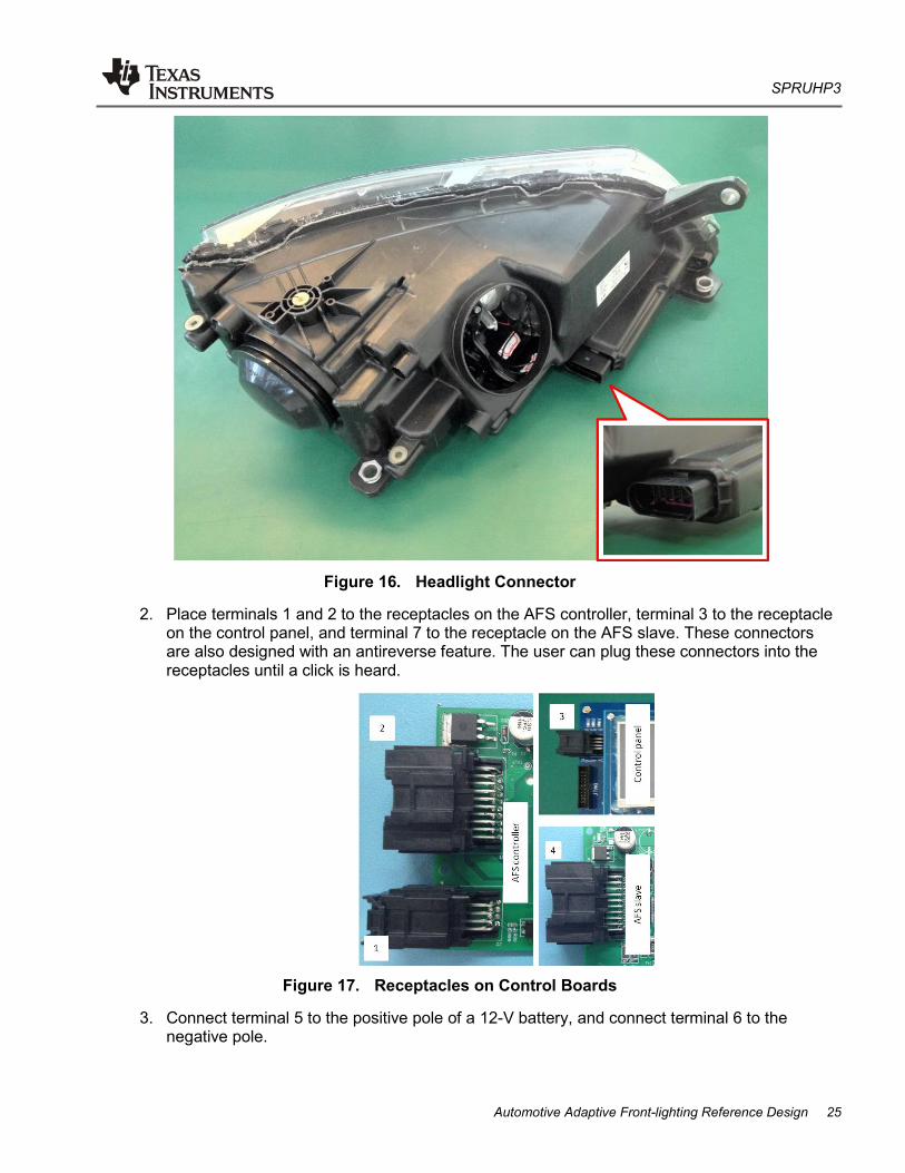
1. Connect terminal 4 to the headlight unit. The receptacle of terminal 4 is at the back side of the light near the bottom. This is an antireverse connector. The user can plug the terminal into the receptacle until a click is heard.
2. Place terminals 1 and 2 to the receptacles on the AFS controller, terminal 3 to the receptacle on the control panel, and terminal 7 to the receptacle on the AFS slave. These connectors are also designed with an antireverse feature. The user can plug these connectors into the receptacles until a click is heard.
Figure 17. Receptacles on Control Boards
3. Connect terminal 5 to the positive pole of a 12-V battery, and connect terminal 6 to the negative pole.
SPRUHP3
26 Automotive Adaptive Front-lighting System Reference Design
CAUTION:
When DC voltage source is to be used instead of a battery, make sure the DC source is capable of more than 200-W power output.
3.1.2 Operation of the Control Panel
The control panel is the human machine interface for the demonstration set. Figure 18 shows the control panel.
Figure 18. Control Panel
The control panel is powered by the 12-V battery through the 8-pin connector. Once the control panel is powered, the user can turn it on or off with the Power key switch.
When the control panel is switched on, the LCD screen is lighted with the TI logo. All buttons with an LED flash once.
There are nine LED buttons, one 3-direction switch, three tuners, and one light sensor on the control board as inputs to the system. All inputs are effective only when the Power key switch is switched on.
There is an SMT-type (RESET) switch on the board; this switch is a reset signal to the MCU on the control panel.
The nine LED buttons are as follows:
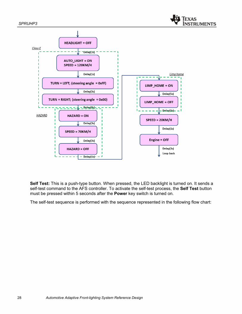
Auto Demo: This is a toggle-type button. When it is activated, LED backlight on the button is turned on. The system enters automatic demo mode. The system ignores all other inputs of the LED buttons, tuners, light sensor, and switch.
Automatic demo is performed with the sequence represented in the following flow chart:
28 Automotive Adaptive Front-lighting System Reference Design
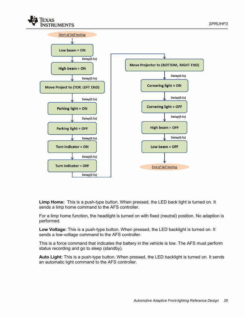
Self Test: This is a push-type button. When pressed, the LED backlight is turned on. It sends a self-test command to the AFS controller. To activate the self-test process, the Self Test button must be pressed within 5 seconds after the Power key switch is turned on.
The self-test sequence is performed with the sequence represented in the following flow chart:
Limp Home: This is a push-type button. When pressed, the LED back light is turned on. It sends a limp home command to the AFS controller.
For a limp home function, the headlight is turned on with fixed (neutral) position. No adaption is performed.
Low Voltage: This is a push-type button. When pressed, the LED backlight is turned on. It sends a low-voltage command to the AFS controller.
This is a force command that indicates the battery in the vehicle is low. The AFS must perform status recording and go to sleep (standby).
Auto Light: This is a push-type button. When pressed, the LED backlight is turned on. It sends an automatic light command to the AFS controller.
SPRUHP3
30 Automotive Adaptive Front-lighting System Reference Design
When automatic light function is activated, the control panel sends the ambient light level data to the AFS controller through the CAN bus according to the light sensor equipped on the control panel. AFS controller detects the vehicle speed and the light level and determines whether to turn on the low beam or to turn it off.
Head Light: This is a push-type button. When pressed, the LED backlight is turned on. It sends a headlight command to the AFS controller.
This button activates and deactivates the low beam on the headlight unit.
High Beam: This is a push-type button. When pressed, the LED backlight is turned on. It sends a high-beam command to the AFS controller.
This button activates and deactivates the high beam on the headlight unit. When High Beam is activated, low beam is automatically activated. (In fact, high-beam control is performed only by turning on and off the high-beam shield.)
Rain: This is a push-type button. When pressed, the LED backlight is turned on. It sends a rain command to the AFS controller.
The rain signal is effective only in Class C and Class E light mode.
Hazard: This is a push-type button. When pressed, the LED backlight is turned on. It sends a hazard command to the AFS controller.
In the demonstration, Hazard has same function as “turn left”.
Turn switch: This is a 3-direction switch that indicates the left and right turn of the vehicle representing the steering column.
The three tuners are as follows:
Direction: This tuner is connected with a potentiometer on the control panel. The value represents the angle of the steering wheel of a car.
Speed: This tuner is connected with a potentiometer on the control panel. The value represents the speed of a car.
Tilt: This tuner is connected with a potentiometer on the control panel. The value represents the tilt level of a car.
The RS232 interface on the control panel is a component that is reserved for future use.
Display on the LCD screen of the control panel:
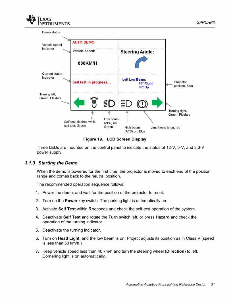
The LCD screen on the control panel displays the status of the AFS.
When the control panel is powered on, the TI logo and AFS Demo are displayed.
A few seconds after starting up, the main screen displays, as shown in Figure 19:
Three LEDs are mounted on the control panel to indicate the status of 12-V, 5-V, and 3.3-V power supply.
3.1.3 Starting the Demo
When the demo is powered for the first time, the projector is moved to each end of the position range and comes back to the neutral position.
The recommended operation sequence follows:
1. Power the demo, and wait for the position of the projector to reset.
2. Turn on the Power key switch. The parking light is automatically on.
3. Activate Self Test within 5 seconds and check the self-test operation of the system.
4. Deactivate Self Test and rotate the Turn switch left, or press Hazard and check the operation of the turning indicator.
5. Deactivate the turning indicator.
6. Turn on Head Light, and the low beam is on. Project adjusts its position as in Class V (speed is less than 50 km/h.)
7. Keep vehicle speed less than 40 km/h and turn the steering wheel (Direction) to left. Cornering light is on automatically.
SPRUHP3
32 Automotive Adaptive Front-lighting System Reference Design
8. Turn Direction back to straight and accelerate to a speed between 50 and 100 km/h. Project adjusts its position as in Class C.
9. Turn Direction to left or right to see the movement of the projector.
10. Turn Tilt up or down to see the movement of the projector.
11. Accelerate the speed to a value greater than 120 km/h, and the projector adjusts its position as in Class E.
12. Turn on Rain so that the projector adjusts its position as in Class W.
13. Turn on and off High Beam to check the operation of the high-beam shield.
14. Set the speed back to a value between 50 to 100 km/h.
15. Turn off high beam and low beam, then turn on Auto Light. To turn off low beam, set car speed lower than 100 km/h and light up the light sensor (for example, by a flash light) at the same time and wait for 5 seconds.
16. Cover the light sensor to check the low beam turning on automatically, or raise the speed to a value greater than 100 km/h.
17. Activate Limp Home to check that the projector goes to a neutral position and being turned on.
18. Activate Auto Demo to check the automatic demo sequence.
19. Turn off the Power key switch.
20. Disconnect the demo from the battery. (Even when the demo is turned off by the Power key switch, all control boards are in STANDBY mode but not powered off.)
4 References 1. UNIFORM PROVISIONS CONCERNING THE APPROVAL OF ADAPTIVE FRONT-
LIGHTING SYSTEMS (AFS) FOR MOTOR VEHICLES, E/ECE/324, Regulation No.123. 2 February 2007
2. ISO7637, part 2. Road vehicles — Electrical disturbances from conduction and coupling. Part 2: Electrical transient conduction along supply lines only. Second Edition, 1 July 2007
3. ISO16750, part 1 and part 2. Road vehicles — Environmental conditions and testing for electrical and electronic equipment. Part 1: General, Part 2: Electrical Load. Second Edition, 1 August 2006
4. GB21259-2007, Headlamps equipped with gas-discharge light sources for motor vehicle. 1 June 2008
5. A Hardware and Software Framework for Automotive Intelligent Lighting. Marko Heiko Hörter and Christoph Stiller, 2009
Texas Instruments Incorporated and its subsidiaries (TI) reserve the right to make corrections, enhancements, improvements and otherchanges to its semiconductor products and services per JESD46, latest issue, and to discontinue any product or service per JESD48, latestissue. Buyers should obtain the latest relevant information before placing orders and should verify that such information is current andcomplete. All semiconductor products (also referred to herein as “components”) are sold subject to TI’s terms and conditions of salesupplied at the time of order acknowledgment.
TI warrants performance of its components to the specifications applicable at the time of sale, in accordance with the warranty in TI’s termsand conditions of sale of semiconductor products. Testing and other quality control techniques are used to the extent TI deems necessaryto support this warranty. Except where mandated by applicable law, testing of all parameters of each component is not necessarilyperformed.
TI assumes no liability for applications assistance or the design of Buyers’ products. Buyers are responsible for their products andapplications using TI components. To minimize the risks associated with Buyers’ products and applications, Buyers should provideadequate design and operating safeguards.
TI does not warrant or represent that any license, either express or implied, is granted under any patent right, copyright, mask work right, orother intellectual property right relating to any combination, machine, or process in which TI components or services are used. Informationpublished by TI regarding third-party products or services does not constitute a license to use such products or services or a warranty orendorsement thereof. Use of such information may require a license from a third party under the patents or other intellectual property of thethird party, or a license from TI under the patents or other intellectual property of TI.
Reproduction of significant portions of TI information in TI data books or data sheets is permissible only if reproduction is without alterationand is accompanied by all associated warranties, conditions, limitations, and notices. TI is not responsible or liable for such altereddocumentation. Information of third parties may be subject to additional restrictions.
Resale of TI components or services with statements different from or beyond the parameters stated by TI for that component or servicevoids all express and any implied warranties for the associated TI component or service and is an unfair and deceptive business practice.TI is not responsible or liable for any such statements.
Buyer acknowledges and agrees that it is solely responsible for compliance with all legal, regulatory and safety-related requirementsconcerning its products, and any use of TI components in its applications, notwithstanding any applications-related information or supportthat may be provided by TI. Buyer represents and agrees that it has all the necessary expertise to create and implement safeguards whichanticipate dangerous consequences of failures, monitor failures and their consequences, lessen the likelihood of failures that might causeharm and take appropriate remedial actions. Buyer will fully indemnify TI and its representatives against any damages arising out of the useof any TI components in safety-critical applications.
In some cases, TI components may be promoted specifically to facilitate safety-related applications. With such components, TI’s goal is tohelp enable customers to design and create their own end-product solutions that meet applicable functional safety standards andrequirements. Nonetheless, such components are subject to these terms.
No TI components are authorized for use in FDA Class III (or similar life-critical medical equipment) unless authorized officers of the partieshave executed a special agreement specifically governing such use.
Only those TI components which TI has specifically designated as military grade or “enhanced plastic” are designed and intended for use inmilitary/aerospace applications or environments. Buyer acknowledges and agrees that any military or aerospace use of TI componentswhich have not been so designated is solely at the Buyer's risk, and that Buyer is solely responsible for compliance with all legal andregulatory requirements in connection with such use.
TI has specifically designated certain components as meeting ISO/TS16949 requirements, mainly for automotive use. In any case of use ofnon-designated products, TI will not be responsible for any failure to meet ISO/TS16949.
Products Applications
Audio www.ti.com/audio Automotive and Transportation www.ti.com/automotive
Amplifiers amplifier.ti.com Communications and Telecom www.ti.com/communications
Data Converters dataconverter.ti.com Computers and Peripherals www.ti.com/computers