Page 1
NOTICE: The manufacturer will accept no responsibility for any electrical damage resulting from improper installation of this product, be that either damage to the vehicle itself or to the installed device. This device must be installed by a certified technician. This guide has been written for properly trained technicians; a certain level of skill & knowledge is therefore assumed. Please review the Installation Guide carefully before beginning any work.
!
Automotive Data Solutions Inc.
INSTALL GUIDE BLADE-TB-KO-EN AvAiLABLE fOr : ADS-BLADE TB
KO
The brand names and logos found in this guide are property of their respective owners. Automotive Data Solutions Inc. © 2013
VErSIoN FrANçAISE DISpoNIbLE EN LIGNE AU www.BLADEUPTADE.cOmpLEASE VISIT www.BLADEUPDATE.cOm For compLETE proDUcT DETAILS
Rev. Date: October 04, 2013Doc. No.: ##12409##
20131003
Page 2
!SECTION
INSTALL TYPE SELECTION
XX-XX PAGE X-XADS-TBSL-KO 1-2 PAGE 2-5
TABLE OF CONTENTS - READ ENTIRE VEHICLE SECTION - 1 OF 2
Ma
KE
MO
dEL
yEa
r
SECT
ION
aC
Ur
a
CL 97-03 C
CSX 06-11 D
EL 1.7 01-05 C
Integra 00-01 C
MDX 01-02 C
MDX 03-06 C
MDX 07-13 D
RDX 07-13 D
RSX 01-06 C
TL 98-03 C
TL 04-08 C
TL w/o Keyless Access 09-13 D
TSX 04-08 C
TSX 09-13 D
CH
EVy Aveo LS 04-08 B
Aveo 5 LS 04-08 B
Epica LS / LT 04-07 B
FOr
d
Contour 98-00 A
Crown Victoria 98-02 A
Crown Victoria 03-09 A
E-Series 08-13 A
Edge 07-10 A
Escape 01-12 A
Escape Hybrid 05-12 A
Excursion 00-05 A
Expedition 99-01 A
Expedition 02-13 A
Explorer 98-01 A
Explorer 02-10 A
Explorer Sport Trac 01 A
Explorer Sport Trac 02-05 A
Explorer Sport Trac 07-10 A
F-Series Super Duty 08-10 A
F150 99-03 A
F150 04-11 A
Fiesta 11-13 A
Five Hundred 05-07 A
Flex 09-12 A
Focus 00-11 A
Freestar 04-07 A
Freestyle 05-07 A
Fusion 06-12 A
Fusion Hybrid 10-12 A
GT 05-06 A
Ma
KE
MO
dEL
yEa
r
SECT
ION
FOr
dMustang 99-04 A
Mustang 05-13 A
Ranger 01-10 A
Ranger 99-01 A
Taurus STD key 00-12 A
Taurus STD key 98-99 A
Taurus X 08-10 A
Thunderbird 02-05 A
Transit Connect 10-13 A
Windstar 01-03 A
Windstar 99-01 A
HO
Nd
a
Accord 98-02 C
Accord 03-07 C
Accord 08-12 D
Accord Hybrid 05-07 C
Civic 12-13 D
Civic 01-05 C
Civic 06-11 D
Civic Hybrid 12-13 D
Civic Hybrid 03-05 C
Civic Hybrid 06-11 D
CR-V 02-06 C
CR-V 07-11 D
CR-V 12-13 D
CR-Z 11-13 D
Element 03-11 C
Fit 07-08 C
Fit 09-13 D
Insight 10-13 D
Insight 00-06 C
Odyssey 98-04 C
Odyssey 05-10 C
Odyssey 11-13 D
Pilot 03-04 C
Pilot 05-08 C
Pilot 09-13 D
Ridgeline 06-13 C
S-2000 06-10 C
S-2000 00-05 C
HyU
Nd
aI
Tiburon V6 2.7L 03-08 E
Tucson V6 2.7L 05-07 E
Tucson V6 2.7L 08-09 E
XG300 01 E
XG350 02-05 E
Ma
KE
MO
dEL
yEa
r
SECT
ION
JaG S-Type 99-08 A
X-Type 02-09 A
KIa
Sedona 04-05 E
Sorento 04-06 E
Sportage V6 2.7L 05-07 E
Sportage V6 2.7L 08-10 E
LEXU
S
ES 300 98-03 F
ES 330 04-06 F
ES 350 07-08 F
GS 300 06 F
GS 300 98-05 F
GS 350 07-08 F
GS 400 98-00 F
GS 430 01-05 F
GS 430 06-07 F
GS 450 Hybrid 07-08 F
GS 460 08 F
GX 470 03-09 F
IS 250 06-08 F
IS 300 01-05 F
IS 350 06-08 F
IS-F 08 F
LS 400 98-00 F
LS 430 01-03 F
LS 430 04-06 F
LS 460 07-08 F
LS 600 Hybrid 08 F
LX 470 98-02 F
LX 470 03-07 F
RX 300 99-03 F
RX 330 04-06 F
RX 350 07-09 F
RX 400 Hybrid 06-08 F
SC 300 98-00 F
SC 400 98-00 F
SC 430 02-09 F
LIN
CO
LN
Aviator 03-05 A
Blackwood 02-03 A
Continental 98-02 A
LS 00-06 A
Mark LT 06-08 A
MKS w/o smartkey 09-12 A
MKX 07-10 A
MKZ 07-12 A
Page 2 of 71 BLADE-TB-KO-EN 20131003
INSTALL GUIDEGuides Français disponibles au WWW.bLADEUpDATE.com
WWW.bLADEUpDATE.com Automotive Data Solutions Inc. © 2013
TraNSpONdEr BypaSS
KO
Doc. No.: ##12409##
Page 3
!SECTION
INSTALL TYPE SELECTION
XX-XX PAGE X-XADS-TBSL-KO 2-2 PAGE 2-2
TABLE OF CONTENTS - READ ENTIRE VEHICLE SECTION - 2 OF 2
Ma
KE
MO
dEL
yEa
r
SECT
ION
LIN
CO
LN
Navigator 99-01 A
Navigator 02-13 A
Town Car 98-02 A
Town Car 03-11 A
Zephyr 06 A
Ma
Zda
2 11-13 A
3 04-09 A
3 w/o smartkey 10-13 A
5 06-13 A
6 03-08 A
6 w/o smartkey 09-13 A
B-Series 01-10 A
B-Series 99-01 A
CX7 07-12 A
CX9 07-13 A
MX-5 06-13 A
RX-8 04-11 A
Tribute 01-11 A
MEr
CU
ry
Cougar 99-02 A
Grand Marquis 98-02 A
Grand Marquis 03-10 A
Marauder 03-04 A
Mariner 05-10 A
Mariner Hybrid 06-10 A
Milan 06-10 A
Montego 05-07 A
Monterey 04-07 A
Mountaineer 98-01 A
Mountaineer 02-10 A
Mystique 98-00 A
Sable 07-09 A
Sable 00-05 A
Sable 98-99 A
pO
NTI
a Vibe 08-10 F
Wave 05-08 B
Wave 5 05-08 B
SCIO
N tC 05-10 F
xB 08-10 F
xD 08-10 F
SZ
Swift+ 04-08 B
Verona 04-06 B
TOyO
Ta 4Runner 99-02 F
4Runner PTS 10 F
4Runner STD key 03-10 F
Ma
KE
MO
dEL
yEa
r
SECT
ION
TOyO
TaAvalon 98-04 F
Avalon 05-09 F
Camry 98-02 F
Camry 03-04 F
Camry 05-06 F
Camry 07-10 F
Camry Hybrid 07-10 F
Corolla 05-08 F
Corolla 09-10 F
FJ Cruiser 07-09 F
Hiace 06-09 F
Highlander 01-03 F
Highlander 04-07 F
Highlander 08-10 F
Highlander Hybrid 06-07 F
Highlander Hybrid 08-10 F
Hilux 04-09 F
Land Cruiser 98-02 F
Land Cruiser 03-07 F
Land Cruiser 08-10 F
Matrix 05-10 F
MR2 Spyder 00-05 F
Prius 04-10 F
RAV4 01-03 F
RAV4 04-08 F
RAV4 09-10 F
Sequoia 01-07 F
Sequoia 08-10 F
Sienna 99-03 F
Sienna 04-10 F
Solara 99-02 F
Solara 03-04 F
Solara 05-09 F
Tacoma 05-10 F
Tundra 06 F
Tundra 07-09 F
Venza STD key 09 F
Yaris 06-11 F
VpG
MV-1 12-13 A
Page 3 of 71 BLADE-TB-KO-EN 20131003
INSTALL GUIDEGuides Français disponibles au WWW.bLADEUpDATE.com
WWW.bLADEUpDATE.com Automotive Data Solutions Inc. © 2013
TraNSpONdEr BypaSS
KO
Doc. No.: ##12409##
Page 4
aSECTION
XX-XX PAGE X-X
INSTALL TYPE SELECTION
ADS-AL(TB)-FM PAGE 2-5M
aK
E
MO
dEL
yEa
r
INST
aLL
Typ
E
NU
MB
Er O
F K
EyS
FOr
d
Contour 98-00 1 1
Crown Victoria 98-02 1 1
Crown Victoria 03-09 1 2
E-Series 08-13 1 2
Edge 07-10 1 2
Escape 01-12 1 2
Escape Hybrid 05-12 1 2
Excursion 00-05 1 1
Expedition 99-01 1 1
Expedition 02-13 1 2
Explorer 98-01 1 1
Explorer 02-10 1 2
Explorer Sport Trac 01 1 1
Explorer Sport Trac 02-05 1 2
Explorer Sport Trac 07-10 1 2
F150 99-03 1 1
F150 04-11 1 2
F-Series Super Duty 08-10 1 2
Fiesta 11-13 1 2
Five Hundred 05-07 1 2
Flex 09-12 1 2
Focus 00-11 1 2
Freestar 04-07 1 2
Freestyle 05-07 1 2
Fusion 06-12 1 2
Fusion Hybrid 10-12 1 2
GT 05-06 1 2
Mustang 99-04 1 1
Mustang 05-13 1 2
Ranger 99-01* 1 1
Ranger **01-10 1 2
Taurus Standard key 98-99 1 1
Taurus Standard key 00-12 1 2
Taurus X 08-10 1 2
Thunderbird 02-05 3 2
Transit Connect 10-13 1 2
Windstar 99-01* 1 1
Windstar **01-03 1 2
JaG
Ua
r S-Type 99-08 3 2
X-Type 02-09 3 2
Ma
KE
MO
dEL
yEa
r
INST
aLL
Typ
E
NU
MB
Er O
F K
EyS
LIN
CO
LNAviator 03-05 1 2
Blackwood 02-03 1 2
Continental 98-02 1 1
LS 00-06 3 2
Mark LT 06-08 1 2
MKS w/o smartkey 09-12 1 2
MKX 07-10 1 2
MKZ 07-12 1 2
Navigator 99-01 1 1
Navigator 02-13 1 2
Town Car 98-02 1 1
Town Car 03-11 1 2
Zephyr 06 1 2
Ma
Zda
2 11-13 1 2
3 04-09 2 2
3 w/o smartkey 10-13 2 2
5 06-13 2 2
6 03-08 2 2
6 w/o smartkey 09-13 2 2
B-Series 99-01* 1 1
B-Series **01-10 1 2
CX7 07-12 2 2
CX9 07-13 2 2
MX-5 06-13 2 2
RX-8 04-11 2 2
Tribute 01-11 1 2
MEr
CU
ry
Cougar 99-02 1 1
Grand Marquis 98-02 1 1
Grand Marquis 03-10 1 2
Marauder 03-04 1 2
Mariner 05-10 1 2
Mariner Hybrid 06-10 1 2
Milan 06-10 1 2
Montego 05-07 1 2
Monterey 04-07 1 2
Mountaineer 98-01 1 1
Mountaineer 02-10 1 2
Mystique 98-00 1 1
Sable 98-99 1 1
Sable 00-05 1 2
Sable 07-09 1 2
VpG
MV-1 12-13 1 2* Vehicles manufactured before 07/24/2000**Vehicles manufactured after 07/24/2000
NOTEI IMPORTANT: some vehicles only
require 1 key for programming.
II KLON service is avaible with the TB-FM2 solution for vehicles that require 2 keys for programming.
Page 4 of 71 BLADE-TB-KO-EN 20131003
INSTALL GUIDEGuides Français disponibles au WWW.bLADEUpDATE.com
WWW.bLADEUpDATE.com Automotive Data Solutions Inc. © 2013
TraNSpONdEr BypaSS
KO
Doc. No.: ##12409##
Page 5
aSECTION
XX-XX PAGE X-XXX-XX PAGE X-X
TYPE 1 - WIRE CROSS REFERENCE CHART - 1 OF 3
ADS-AL(TB)-FM T1 1-3 PAGE X-X
Ma
KE
MO
dEL
yEa
r
TX rX CONNECTOr
pO
SITI
ON
WIr
E C
OLO
r
pO
SITI
ON
WIr
E C
OLO
r
LOCa
TIO
N
FOr
d
Contour 98-00 3 Gray/Orange 4 White/LtGreen B
Crown Victoria 98-02 4 White/LtGreen 3 Gray/Orange A
Crown Victoria 03-04 4 White/LtGreen 3 Gray/Orange C
Crown Victoria 05-09 3 White/LtGreen 4 Gray/Orange E
E-Series 08 4 White/LtGreen 3 Gray/Orange C
E-Series 09-13 4 Yellow/Orange 3 Violet/Gray C
Edge 07-10 3 Violet/Gray 4 Yellow/Orange E
Escape / Hybrid 01-07 3 Brown/Orange 4 Red/Black B
Escape / Hybrid 08-12 3 Yellow/Orange 4 Violet/Gray E
Excursion 00-02/03* 4 White/LtGreen 3 Gray/Orange A
Excursion 03**/04-05 4 White/LtGreen 3 Gray/Orange C
Expedition 99-02 4 White/LtGreen 3 Gray/Orange A
Expedition 03-06 3 White/LtGreen 4 Gray/Orange B
Expedition 07-13 3 Violet/Brown 4 Blue/Gray E
Explorer 98-00/01* 4 White/LtGreen 3 Gray/Orange A
Explorer (2dr) 01**/02-03 4 White/LtGreen 3 Gray/Orange C
Explorer 02-05 3 White/LtGreen 4 Gray/Orange B
Explorer 06-10 3 Yellow/Orange 4 Violet/Gray E
Explorer Sport Trac 01* 4 White/LtGreen 3 Gray/Orange A
Explorer Sport Trac 01**/02-05 4 White/LtGreen 3 Gray/Orange C
Explorer Sport Trac 07-10 3 Yellow/Orange 4 Violet/Gray E
F-150 99-02 4 White/LtGreen 3 Gray/Orange A
F-150 03 4 White/LtGreen 3 Gray/Orange C
F-150 04-08 3 White/LtGreen 4 Gray/Orange B
F-150 09-11 3 Violet/Gray*** 4 Yellow/Orange*** E
F-Series Super Duty 08-10 3 Yellow/Orange 4 Violet/Gray E
Fiesta 11-13 3 Yellow/Orange 4 Violet/Gray E
Five Hundred 05-07 3 White/LtGreen 4 Gray/Orange E
Flex 09-12 3 Yellow/Orange 4 Violet/Gray E
Focus 00-07 3 Gray/Orange 4 White/Green B
Focus 08-11 4 Violet/Gray*** 3 Yellow/Orange*** E
Freestar 04-07 4 White/LtGreen 3 Gray/Orange C
Freestyle 05-07 3 White/LtGreen 4 Gray/Orange E
Fusion 06/07* 3 Violet/Gray 4 Yellow/Orange E
Fusion 07**/08-12 3 Yellow/Orange 4 Violet/Gray E
GT 05-06 3 White/Orange 4 Brown/Orange B
Mustang 99-02 4 White/LtGreen 3 Gray/Orange A
Mustang 03-04 4 White/LtGreen 3 Gray/Orange C
Mustang 05-09 3 White/LtGreen 4 Gray/Orange E
Mustang 10-13 3 Violet/Gray 4 Yellow/Red E
Ranger 99-00 4 White/LtGreen 3 Gray/Orange A
Ranger 01-06 4 White/LtGreen 3 Gray/Orange C
Ranger 07-10 4 Violet/Brown 3 Blue/Gray C
Taurus 98-01 4 Brown/Orange 3 Red/Black A
Taurus 02 4 Gray/Red 3 Brown/Yellow A
Taurus 03 4 Brown/Yellow 3 Gray/Red C
* EarLy prOdUCTION** LaTE prOdUCTION*** COLOrS May Vary BUT pIN OUT IS COrrECT
Page 5 of 71 BLADE-TB-KO-EN 20131003
INSTALL GUIDEGuides Français disponibles au WWW.bLADEUpDATE.com
WWW.bLADEUpDATE.com Automotive Data Solutions Inc. © 2013
TraNSpONdEr BypaSS
KO
Doc. No.: ##12409##
Page 6
aSECTION
XX-XX PAGE X-XXX-XX PAGE X-X
TYPE 1 - WIRE CROSS REFERENCE CHART - 2 OF 3
ADS-AL(TB)-FM T1 2-3 PAGE X-X
Ma
KE
MO
dEL
yEa
r
TX rX CONNECTOr
pO
SITI
ON
WIr
E C
OLO
r
pO
SITI
ON
WIr
E C
OLO
r
LOCa
TIO
N
FOr
d
Taurus 04-07 4 White/LtGreen 3 Gray/Orange C
Taurus 08-12 3 Yellow/Orange 4 Violet/Gray E
Taurus X 08-10 3 Yellow/Orange 4 Violet/Gray E
Transit Connect 10 4 White/Green 3 Gray/Orange A
Transit Connect 11-13 3 White/Green 4 Gray/Orange A
Windstar 99-02 4 White/LtGreen 3 Gray/Orange A
Windstar 03 4 White/LtGreen 3 Gray/Orange C
LIN
CO
LN
Aviator 03-05 3 White/LtGreen 4 Gray/Orange B
Blackwood 02 4 White/LtGreen 3 Gray/Orange A
Blackwood 03 4 White/LtGreen 3 Gray/Orange C
Continental 98* 3 White/LtGreen 4 Gray/Orange A
Continental 98**/99-02 4 White/LtGreen 3 Gray/Orange A
Mark LT 06-08 3 White/LtGreen 4 Gray/Orange B
MKS (w/o smartkey) 09-12 3 Yellow/Orange 4 Violet/Gray E
MKX 07-10 3 Violet/Gray 4 Yellow/Orange E
MKZ 07* 3 Violet/Gray 4 Yellow/Orange E
MKZ 07**/08-12 3 Yellow/Orange 4 Violet/Gray E
Navigator 99-02 4 White/LtGreen 3 Gray/Orange A
Navigator 03-06 3 White/LtGreen 4 Gray/Orange B
Navigator 07-13 3 Violet/Brown 4 Blue/Gray E
Town Car 98-02 4 White/LtGreen 3 Gray/Orange A
Town Car 03-04 4 White/LtGreen 3 Gray/Orange C
Town Car 05-11 3 White/LtGreen 4 Gray/Orange E
Zephyr 06 3 Violet/Gray 4 Yellow/Orange E
Ma
Zda
2 11-13 4 Gray 3 Green H
B-Series 99-00 4 White/LtGreen 3 Gray/Orange A
B-Series 01-06 4 White/LtGreen 3 Gray/Orange C
B-Series 07-10 4 Violet/Brown 3 Blue/Gray C
Tribute 01-07 3 Brown/Orange 4 Red/Black B
Tribute 08-11 3 Yellow/Orange 4 Violet/Gray E
MEr
CU
ry
Cougar 99-02 3 Gray/Orange 4 White/Green B
Grand Marquis 98-02 4 White/LtGreen 3 Gray/Orange A
Grand Marquis 03-04 4 White/LtGreen 3 Gray/Orange C
Grand Marquis 05-10 3 White/LtGreen 4 Gray/Orange E
Marauder 03-04 4 White/LtGreen 3 Gray/Orange C
Mariner / Hybrid 05-07 3 Brown/Orange 4 Red/Black B
Mariner / Hybrid 08-10 3 Yellow/Orange 4 Violet/Gray E
Milan 06/07* 3 Violet/Gray 4 Yellow/Orange E
Milan 07**/08-10 3 Yellow/Orange 4 Violet/Gray E
Montego 05-07 3 White/LtGreen 4 Gray/Orange E
Monterey 04-07 4 White/LtGreen 3 Gray/Orange C
Mountaineer 98-01 4 White/LtGreen 3 Gray/Orange A
Mountaineer 02-05 3 White/LtGreen 4 Gray/Orange B
Mountaineer 06-10 3 Yellow/Orange 4 Violet/Gray E
Mystique 98-00 3 Gray/Orange 4 White/LtGreen B
Sable 98-01 4 Brown/Orange 3 Red/Black A * EarLy prOdUCTION** LaTE prOdUCTION
Page 6 of 71 BLADE-TB-KO-EN 20131003
INSTALL GUIDEGuides Français disponibles au WWW.bLADEUpDATE.com
WWW.bLADEUpDATE.com Automotive Data Solutions Inc. © 2013
TraNSpONdEr BypaSS
KO
Doc. No.: ##12409##
Page 7
aSECTION
TYPE 1 - WIRE CROSS REFERENCE CHART - 3 OF 3
ADS-AL(TB)-FM T1 3-3 PAGE X-X
Ma
KE
MO
dEL
yEa
r
TX rX CONNECTOr
pO
SITI
ON
WIr
E C
OLO
r
pO
SITI
ON
WIr
E C
OLO
r
LOCa
TIO
N
MEr
CU
ry Sable 02 4 Gray/Red 3 Brown/Yellow A
Sable 03 4 Brown/Yellow 3 Gray/Red C
Sable 04-05 4 White/LtGreen 3 Gray/Orange C
Sable 08-09 3 Yellow/Orange 4 Violet/Gray E
VpG
MV-1 12-13 4 Yellow/Orange 3 Violet/Gray C
Page 7 of 71 BLADE-TB-KO-EN 20131003
INSTALL GUIDEGuides Français disponibles au WWW.bLADEUpDATE.com
WWW.bLADEUpDATE.com Automotive Data Solutions Inc. © 2013
TraNSpONdEr BypaSS
KO
Doc. No.: ##12409##
Page 8
aSECTION
TYPE 1 - WIRING DIAGRAM
1 2 3 4 5 6
YX
3 4
1234
43
21
4321 5678 1234
4 123
1234
344 3
3 4
124 33 4
BROWN/RED (NC)BROWN/RED (NC)
BLUE/RED (NC)BLUE/RED (NC)
YELLOW (NC)YELLOW (NC)
BROWN/YELLOW (NC)BROWN/YELLOW (NC)ORANGE/BLACK - ECM RXORANGE/BLACK - ECM RXORANGE/WHITE (NC)ORANGE/WHITE (NC)ORANGE (NC)ORANGE (NC)PINK/BLACK (NC)PINK/BLACK (NC)
BLUE/YELLOW (NC)BLUE/YELLOW (NC)GREEN/RED (NC)GREEN/RED (NC)
BLACK (NC)BLACK (NC)
GRAY/RED - ECM TXGRAY/RED - ECM TXGRAY/YELLOW (NC)GRAY/YELLOW (NC)
PINK (NC)PINK (NC)
WHITE/BLACK (NC)WHITE/BLACK (NC)WHITE/RED (NC)WHITE/RED (NC)WHITE (NC)WHITE (NC)
RX TX
TXRXGROUND
IGN.
CONNECTOR D- WHITELOCATED AT IMMOBILIZER
NEAR KEY BARREL
TX PATS 12V
RX GROUND
GROUND
PATS 12V
GROUND
PATS 12V
PATS 12V
GROUND
GROUND
TX RXTX RXTX RX
PATS 12V
GROUND
TXRX
PATS 12VTXRX
CONNECTOR A - WHITEFOUND 8 INCHES LOWER
ON PATS HARNESS
CONNECTOR C - GREENFOUND 8 INCHES LOWER
ON PATS HARNESS
CONNECTOR F - WHITELOCATED AT IMMOBILIZER
NEAR KEY BARREL
CONNECTOR B - GREENLOCATED AT IMMOBILIZER
NEAR KEY BARREL
CONNECTOR E - BLACKLOCATED AT IMMOBILIZER
NEAR KEY BARREL
CONNECTOR HLOCATED AT IMMOBILIZER
NEAR KEY BARRELREMOTE STARTER
01
02
03
04
05
06
07
08
09
10
11
12
13
14
15
16
17
18
19
20
GRAY/RED GRAY/YELLOW
BLUE/YELLOW
YELLOWGREEN/RED
BLUE/RED
NO WIREORANGE
ORANGE/WHITEORANGE/BLACK
BROWN/YELLOWBROWN/RED
BLACKNO WIRE
PINKPINK/BLACK
NO WIREWHITE
WHITE/BLACKWHITE/RED
*BLADE CONNECTOR EXACT PIN-OUT
Page 8 of 71 BLADE-TB-KO-EN 20131003
INSTALL GUIDEGuides Français disponibles au WWW.bLADEUpDATE.com
WWW.bLADEUpDATE.com Automotive Data Solutions Inc. © 2013
TraNSpONdEr BypaSS
KO
Doc. No.: ##12409##
Page 9
aSECTION
XX-XX PAGE X-XXX-XX PAGE X-X
TYPE 2 - WIRE CROSS REFERENCE CHART - 1 OF 1
ADS-AL(TB)-FM T2 1-1 PAGE X-X
Ma
KE
MO
dEL
yEa
r
TX rX CONNECTOr
pO
SITI
ON
WIr
E C
OLO
r
pO
SITI
ON
WIr
E C
OLO
r
LOCa
TIO
N
Ma
Zda
3 04-09 2 Gray/Orange 1 White/LtGreen D
3 (w/o smartkey) 10-13 2 LtBlue 1 Blue D
5 06-10 2 Green 1 Pink/Black D
5 11-13 2 LtBlue/Orange 1 Gray D
6 (w/o smartkey) 03-08 2 Green 1 Orange/LtBlue D
6 (with smartkey) 06-08 2 Yellow/Green 1 Gray D
6 (w/o smartkey) 09-13 4 Gray/Orange 3 White/LtGreen F
CX7 07-12 2 Gray/Orange 1 White/LtGreen D
CX9 07-13 2 Blue/Yellow 1 Blue/Orange D
MX-5 (w/o smartkey) 06-13 2 Yellow/Black 1 LtBlue/Orange D
MX-5 (with smartkey) 06-13 2 Gray/LtBlue 1 Violet D
RX-8 04-11 2 LtBlue/Orange 1 Yellow/Black D
Page 9 of 71 BLADE-TB-KO-EN 20131003
INSTALL GUIDEGuides Français disponibles au WWW.bLADEUpDATE.com
WWW.bLADEUpDATE.com Automotive Data Solutions Inc. © 2013
TraNSpONdEr BypaSS
KO
Doc. No.: ##12409##
Page 10
aSECTION
TYPE 2 - WIRING DIAGRAM
YX
1234
43
21
4321 5678 1234
4 123
1234
344 3
3 4
124 33 4
BROWN/RED (NC)BROWN/RED (NC)
BLUE/RED (NC)BLUE/RED (NC)
YELLOW (NC)YELLOW (NC)
BROWN/YELLOW (NC)BROWN/YELLOW (NC)ORANGE/BLACK - RX VEHICLE SIDEORANGE/BLACK - RX VEHICLE SIDEORANGE/WHITE (NC)ORANGE/WHITE (NC)ORANGE (NC)ORANGE (NC)PINK/BLACK (NC)PINK/BLACK (NC)
BLUE/YELLOW (NC)BLUE/YELLOW (NC)GREEN/RED (NC)GREEN/RED (NC)
BLACK (NC)BLACK (NC)
GRAY/RED - ECM TXGRAY/RED - ECM TXGRAY/YELLOW (NC)GRAY/YELLOW (NC)
PINK (NC)PINK (NC)
WHITE/BLACK - RX CONNECTOR SIDEWHITE/BLACK - RX CONNECTOR SIDEWHITE/RED - RX VEHICLE SIDEWHITE/RED - RX VEHICLE SIDEWHITE (NC)WHITE (NC)
RX TX
CONNECTOR D- WHITELOCATED AT IMMOBILIZER
NEAR KEY BARREL
TX PATS 12V
RX GROUND
GROUND
PATS 12V
GROUND
PATS 12V
PATS 12V
GROUND
GROUND
TX RXTX RXTX RX
PATS 12V
GROUND
TXRX
PATS 12VTXRX
CONNECTOR A - WHITEFOUND 8 INCHES LOWER
ON PATS HARNESS
CONNECTOR C - GREENFOUND 8 INCHES LOWER
ON PATS HARNESS
CONNECTOR F - WHITELOCATED AT IMMOBILIZER
NEAR KEY BARREL
CONNECTOR B - GREENLOCATED AT IMMOBILIZER
NEAR KEY BARREL
CONNECTOR E - BLACKLOCATED AT IMMOBILIZER
NEAR KEY BARREL
REMOTE STARTER
01
02
03
04
05
06
07
08
09
10
11
12
13
14
15
16
17
18
19
20
GRAY/RED GRAY/YELLOW
BLUE/YELLOW
YELLOWGREEN/RED
BLUE/RED
NO WIREORANGE
ORANGE/WHITEORANGE/BLACK
BROWN/YELLOWBROWN/RED
BLACKNO WIRE
PINKPINK/BLACK
NO WIREWHITE
WHITE/BLACKWHITE/RED
*BLADE CONNECTOR EXACT PIN-OUT
Page 10 of 71 BLADE-TB-KO-EN 20131003
INSTALL GUIDEGuides Français disponibles au WWW.bLADEUpDATE.com
WWW.bLADEUpDATE.com Automotive Data Solutions Inc. © 2013
TraNSpONdEr BypaSS
KO
Doc. No.: ##12409##
Page 11
aSECTION
Ma
KE
MO
dEL
yEa
r
TX rX paTS pOWEr CONNECTOr
pO
SITI
ON
WIr
E C
OLO
r
pO
SITI
ON
WIr
E C
OLO
r
pO
SITI
ON
WIr
E C
OLO
r
LOCa
TIO
N
FOr
d
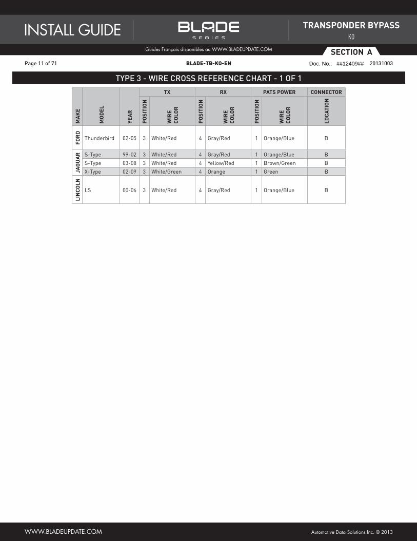
Thunderbird 02-05 3 White/Red 4 Gray/Red 1 Orange/Blue B
JaG
Ua
r S-Type 99-02 3 White/Red 4 Gray/Red 1 Orange/Blue B
S-Type 03-08 3 White/Red 4 Yellow/Red 1 Brown/Green B
X-Type 02-09 3 White/Green 4 Orange 1 Green B
LIN
CO
LN
LS 00-06 3 White/Red 4 Gray/Red 1 Orange/Blue B
TYPE 3 - WIRE CROSS REFERENCE CHART - 1 OF 1
ADS-AL(TB)-FM T3 1-1 PAGE X-X
Page 11 of 71 BLADE-TB-KO-EN 20131003
INSTALL GUIDEGuides Français disponibles au WWW.bLADEUpDATE.com
WWW.bLADEUpDATE.com Automotive Data Solutions Inc. © 2013
TraNSpONdEr BypaSS
KO
Doc. No.: ##12409##
Page 12
aSECTION
TYPE 3 - WIRING DIAGRAM
1234 3 14
7.5 AMPS
BROWN/RED (NC)BROWN/RED (NC)
BLUE/RED (NC)BLUE/RED (NC)
YELLOW (NC)YELLOW (NC)
BROWN/YELLOW (NC)BROWN/YELLOW (NC)ORANGE/BLACK - ECM RXORANGE/BLACK - ECM RXORANGE/WHITE (NC)ORANGE/WHITE (NC)ORANGE (NC)ORANGE (NC)PINK/BLACK (NC)PINK/BLACK (NC)
BLUE/YELLOW (NC)BLUE/YELLOW (NC)GREEN/RED (NC)GREEN/RED (NC)
BLACK (NC)BLACK (NC)
GRAY/RED - ECM TXGRAY/RED - ECM TXGRAY/YELLOW (NC)GRAY/YELLOW (NC)
PINK (NC)PINK (NC)
WHITE/BLACK (NC)WHITE/BLACK (NC)WHITE/RED (NC)WHITE/RED (NC)WHITE (NC)WHITE (NC)
IGNITION (+)
REMOTE STARTER
01
02
03
04
05
06
07
08
09
10
11
12
13
14
15
16
17
18
19
20
GRAY/RED GRAY/YELLOW
BLUE/YELLOW
YELLOWGREEN/RED
BLUE/RED
NO WIREORANGE
ORANGE/WHITEORANGE/BLACK
BROWN/YELLOWBROWN/RED
BLACKNO WIRE
PINKPINK/BLACK
NO WIREWHITE
WHITE/BLACKWHITE/RED
*BLADE CONNECTOR EXACT PIN-OUT
CONNECT TO THE VEHICLEMAIN IGNITION.
DO NOT USE THE OEM CIRCUITRY.THE MODIFICATION WILL PERMANENTLY
REMAIN IN THE VEHICLE.
SECURE AND INSULATETHE WIRE ON
THE VEHICLE SIDE
GROUND
PATS 12V (+) POWER
VEHICLE MAIN IGNITION (+)
TXRX
CONNECTOR B - GREENLOCATED AT IMMOBILIZER
NEAR KEY BARREL
Page 12 of 71 BLADE-TB-KO-EN 20131003
INSTALL GUIDEGuides Français disponibles au WWW.bLADEUpDATE.com
WWW.bLADEUpDATE.com Automotive Data Solutions Inc. © 2013
TraNSpONdEr BypaSS
KO
Doc. No.: ##12409##
Page 13
aSECTION
CARTRIDGE INSTALLATION
1 Slide cartridge into unit. Notice button under LED. 2 Ready for Module Programming
Procedure.
Page 13 of 71 BLADE-TB-KO-EN 20131003
INSTALL GUIDEGuides Français disponibles au WWW.bLADEUpDATE.com
WWW.bLADEUpDATE.com Automotive Data Solutions Inc. © 2013
TraNSpONdEr BypaSS
KO
Doc. No.: ##12409##
Page 14
aSECTION
7 Wait, LED will turn solid RED then will turn OFF.
MODULE PROGRAMMING PROCEDURE - WITH TWO OEM KEYS
1 Insert key 1 into ignition.
5 Insert key 2 into ignition.
3 If LED turns solid GREEN for 2 seconds. Module Programming Procedure completed.
If LED turns solid RED, proceed with following step within 5 seconds, after LED turns OFF.
2 Turn key 1 to ON position.
ON
6 Turn key 2 to ON position.
ON
! If the LED begins to fl ash RED, verify the RX and TX connections between the module and the vehicle.
NOTEI To complete this procedure,
both OEM keys are required.
II Keep both OEM remotes at least 10 feet away from the vehicule.
Use both valet keys for the module programming procedure.
OR
4 Remove key.
8 Remove key.
10 Remote start vehicle.
OR
Jump the igntion to 12volts.
12V
IGNITION
10 AMPS
12 Module Programming Procedure completed.
! If the LED begins to fl ash RED, you are using a cloned key or used the same key twice.
9 Press and release programming button.
11 Wait, LED will turn solid RED then will turn solid GREEN.
Page 14 of 71 BLADE-TB-KO-EN 20131003
INSTALL GUIDEGuides Français disponibles au WWW.bLADEUpDATE.com
WWW.bLADEUpDATE.com Automotive Data Solutions Inc. © 2013
TraNSpONdEr BypaSS
KO
Doc. No.: ##12409##
Page 15
BSECTION
INSTALL TYPE SELECTION
XX-XX PAGE X-XADS-TB-GD PAGE 2-2
Ma
KE
MO
dEL
yEa
r
INST
aLL
Typ
E
CH
EVr
OLE
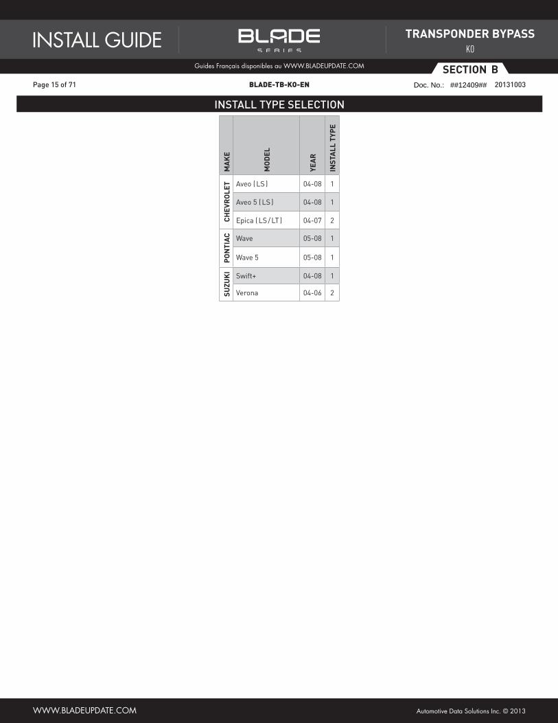
T Aveo ( LS ) 04-08 1
Aveo 5 ( LS ) 04-08 1
Epica ( LS / LT ) 04-07 2p
ON
TIa
C Wave 05-08 1
Wave 5 05-08 1
SUZU
KI
Swift+ 04-08 1
Verona 04-06 2
Page 15 of 71 BLADE-TB-KO-EN 20131003
INSTALL GUIDEGuides Français disponibles au WWW.bLADEUpDATE.com
WWW.bLADEUpDATE.com Automotive Data Solutions Inc. © 2013
TraNSpONdEr BypaSS
KO
Doc. No.: ##12409##
Page 16
BSECTION
XX-XX PAGE X-X
TYPE 1 - WIRE CROSS REFERENCE CHART
ADS-AL(TB)-GD T1 PAGE X-X
Ma
KE
MO
dEL
yEa
r
IGNITION daTa CONNECTOr
pO
SITI
ON
WIr
E C
OLO
r
pO
SITI
ON
WIr
E C
OLO
r
Na
ME
Typ
E
LOCa
TIO
N
CH
EVr
OLE
T Aveo ( LS ) 04-07 1 Pink 6 Black/White D 7 pin At key barrel
Aveo ( LS ) 08 1 Pink 6 Brown/White D 7 pin At key barrel
Aveo 5 ( LS ) 04-07 1 Pink 6 Black/White D 7 pin At key barrel
Aveo 5 ( LS ) 08 1 Pink 6 Brown/White D 7 pin At key barrel
pO
NTI
aC Wave 05-07 1 Pink 6 Black/White D 7 pin At key barrel
Wave 08 1 Pink 6 Brown/White D 7 pin At key barrel
Wave 5 05-07 1 Pink 6 Black/White D 7 pin At key barrel
Wave 5 08 1 Pink 6 Brown/White D 7 pin At key barrel
SUZU
KI Swift+ 04-07 1 Pink 6 Black/White D 7 pin At key barrel
Swift+ 08 1 Pink 6 Brown/White D 7 pin At key barrel
Page 16 of 71 BLADE-TB-KO-EN 20131003
INSTALL GUIDEGuides Français disponibles au WWW.bLADEUpDATE.com
WWW.bLADEUpDATE.com Automotive Data Solutions Inc. © 2013
TraNSpONdEr BypaSS
KO
Doc. No.: ##12409##
Page 17
BSECTION
TYPE 1 - WIRING DIAGRAM
WHITE/BLACK - ALARM INPUT ECMWHITE/BLACK - ALARM INPUT ECMWHITE/RED - ALARM OUTPUT FUSEWHITE/RED - ALARM OUTPUT FUSEWHITE (NC)WHITE (NC)
BROWN/RED (NC)BROWN/RED (NC)
BLUE/RED (NC)BLUE/RED (NC)
YELLOW (NC)YELLOW (NC)
BROWN/YELLOW (NC)BROWN/YELLOW (NC)ORANGE/BLACK - DATAORANGE/BLACK - DATAORANGE/WHITE (NC)ORANGE/WHITE (NC)ORANGE (NC)ORANGE (NC)PINK/BLACK - IGNITION OUTPUTPINK/BLACK - IGNITION OUTPUT
BLUE/YELLOW (NC)BLUE/YELLOW (NC)GREEN/RED (NC)GREEN/RED (NC)
BLACK (NC)BLACK (NC)
GRAY/RED (NC)GRAY/RED (NC)GRAY/YELLOW (NC)GRAY/YELLOW (NC)
PINK - IGNITION INPUTPINK - IGNITION INPUT
PINK - OEM ALARM IGNITION (BEHIND CENTER CONSOLE)
PINK - IGNITION FROM ECM
D CONNECTOR - FRONT VIEW
OPTIONALIF THE IGNITION WIRE (LOCATED BEHINDCENTER CONSOLE) IS INTERRUPTED BY
MODULE, THERE IS NO NEED TO OVERRIDETHE VEHICLE FACTORY ALARM.
THIS INSTALLATION METHOD WILL ENSUREYOUR FACTORY KEYFOB TO FUNCTIONNORMALLY AT ALL TIMES (INCLUDING
DURING REMOTE START).
BLACK/WHITE OR BROW
N/WHITE
DATA
REMOTE STARTER
01
02
03
04
05
06
07
08
09
10
11
12
13
14
15
16
17
18
19
20
GRAY/RED GRAY/YELLOW
BLUE/YELLOW
YELLOWGREEN/RED
BLUE/RED
NO WIREORANGE
ORANGE/WHITEORANGE/BLACK
BROWN/YELLOWBROWN/RED
BLACKNO WIRE
PINKPINK/BLACK
NO WIREWHITE
WHITE/BLACKWHITE/RED
*BLADE CONNECTOR EXACT PIN-OUT
Page 17 of 71 BLADE-TB-KO-EN 20131003
INSTALL GUIDEGuides Français disponibles au WWW.bLADEUpDATE.com
WWW.bLADEUpDATE.com Automotive Data Solutions Inc. © 2013
TraNSpONdEr BypaSS
KO
Doc. No.: ##12409##
Page 18
BSECTION
XX-XX PAGE X-X
WIRE CROSS REFERENCE CHART
XX-XX PAGE X-X
TYPE 2 - WIRE CROSS REFERENCE CHART
ADS-AL(TB)-GD T2 PAGE X-X
Ma
KE
MO
dEL
yEa
r
daTa CONNECTOr SECUrITy LIGHT CONNECTOr
pO
SITI
ON
WIr
E C
OLO
r
Na
ME
Typ
E
LOCa
TIO
N
pO
SITI
ON
WIr
E C
OLO
r
Na
ME
Typ
E
LOCa
TIO
N
CH
EVr
OLE
T
Epica ( LS / LT ) 04-07 7 Green/Black E 15 pin At BCM 20 Yellow/Black F 30 pin At BCM
SUZU
KI
Verona 04-06 7 Green/Black E 15 pin At BCM 20 Yellow/Black F 30 pin At BCM
Page 18 of 71 BLADE-TB-KO-EN 20131003
INSTALL GUIDEGuides Français disponibles au WWW.bLADEUpDATE.com
WWW.bLADEUpDATE.com Automotive Data Solutions Inc. © 2013
TraNSpONdEr BypaSS
KO
Doc. No.: ##12409##
Page 19
BSECTION
TYPE 2 - WIRING DIAGRAM
4321 8765 1211109 1514137
4321 8765 1211109 151413
19181716 23222120 27262524 30291820
WHITE/BLACK - DATA BCM SIDEWHITE/BLACK - DATA BCM SIDEWHITE/RED - DATA ECM SIDEWHITE/RED - DATA ECM SIDEWHITE (NC)WHITE (NC)
BROWN/RED (NC)BROWN/RED (NC)
BLUE/RED - SECURITY LIGHT INPUTBLUE/RED - SECURITY LIGHT INPUT
YELLOW (NC)YELLOW (NC)
BROWN/YELLOW (NC)BROWN/YELLOW (NC)ORANGE/BLACK - DATAORANGE/BLACK - DATAORANGE/WHITE (NC)ORANGE/WHITE (NC)ORANGE (NC)ORANGE (NC)PINK/BLACK (NC)PINK/BLACK (NC)
BLUE/YELLOW - SECURITY LIGHT OUTPUTBLUE/YELLOW - SECURITY LIGHT OUTPUTGREEN/RED (NC)GREEN/RED (NC)
BLACK (NC)BLACK (NC)
GRAY/RED (NC)GRAY/RED (NC)GRAY/YELLOW (NC)GRAY/YELLOW (NC)
PINK (NC)PINK (NC)
DATA - GREEN/BLACK
SECURITY LIGHT - YELLOW/BLACK
F CONNECTORLOCATED AT BCM
E CONNECTORLOCATED AT BCM
REMOTE STARTER
01
02
03
04
05
06
07
08
09
10
11
12
13
14
15
16
17
18
19
20
GRAY/RED GRAY/YELLOW
BLUE/YELLOW
YELLOWGREEN/RED
BLUE/RED
NO WIREORANGE
ORANGE/WHITEORANGE/BLACK
BROWN/YELLOWBROWN/RED
BLACKNO WIRE
PINKPINK/BLACK
NO WIREWHITE
WHITE/BLACKWHITE/RED
*BLADE CONNECTOR EXACT PIN-OUT
Page 19 of 71 BLADE-TB-KO-EN 20131003
INSTALL GUIDEGuides Français disponibles au WWW.bLADEUpDATE.com
WWW.bLADEUpDATE.com Automotive Data Solutions Inc. © 2013
TraNSpONdEr BypaSS
KO
Doc. No.: ##12409##
Page 20
BSECTION
MODULE PROGRAMMING
XX-XX PAGE X-XBLADE-AL(TB)- PAGE X-X
CARTRIDGE INSTALLATION
2 Ready for Module Programming Procedure.1 Slide cartridge into unit. Notice
button under LED.
BLADE-TB-C1 61 BLADE-TB-C2 61 BLADE-TB-GD 61 BLADE-TB-GM 61 BLADE-TB-HA 61 BLADE-TB-HA 61 BLADE-TB-HA1 61BLADE-TB-HA2 61 BLADE-TB-HK 61 BLADE-TB-MA 61 BLADE-TB-NI 61 BLADE-TB-PR 61
MODULE PROGRAMMING PROCEDURE
5 Module Programming Procedure completed.
4 Turn key to OFF position.OFF
1 Insert key into ignition.
2 Turn key to ON position.
ON
3 Wait, LED will turn solid GREEN for 2 seconds.
MODULE PROGRAMMING PROCEDURE WITH PUSH TO START SYSTEM
4 Module Programming Procedure completed.
1 Push start button twice [2x] to ON position.
DO NOT PRESS BRAKE PEDAL
x2 3 Push start button once [1x] to OFF position.
DO NOT PRESS BRAKE PEDAL
x12 Wait, LED will turn solid GREEN
for 2 seconds.
Page 20 of 71 BLADE-TB-KO-EN 20131003
INSTALL GUIDEGuides Français disponibles au WWW.bLADEUpDATE.com
WWW.bLADEUpDATE.com Automotive Data Solutions Inc. © 2013
TraNSpONdEr BypaSS
KO
Doc. No.: ##12409##
Page 21
CSECTION
INSTALL TYPE SELECTION
XX-XX PAGE X-XADS-TB-HA1 PAGE 2-2
Ma
KE
MO
dEL
yEa
r
INST
aLL
Typ
E
aC
Ur
a
CL 97-03 1
EL 1.7 01-05 2
Integra 00-01 1
MDX 01-02 1
MDX 03-06 2
RSX 01-06 2
TL 98-03 1
TL 04-08 2
TSX 04-08 2
HO
Nd
a
Accord 98-02 1
Accord 03-07 2
Accord Hybrid 05-07 2
Civic 01-05 2
Civic Hybrid 03-05 2
CR-V 02-06 2
Element 03-11 2
Fit 07-08 2
Insight 00-06 1
Odyssey 98-04 1
Odyssey 05-10 2
Pilot 03-04 1
Pilot 05-08 2
S-2000 00-05 1
S-2000 06-10 2
Ridgeline 06-13 2
Page 21 of 71 BLADE-TB-KO-EN 20131003
INSTALL GUIDEGuides Français disponibles au WWW.bLADEUpDATE.com
WWW.bLADEUpDATE.com Automotive Data Solutions Inc. © 2013
TraNSpONdEr BypaSS
KO
Doc. No.: ##12409##
Page 22
CSECTION
XX-XX PAGE X-X
WIRE CROSS REFERENCE CHART
XX-XX PAGE X-XXX-XX PAGE X-X
TYPE 1 - WIRE CROSS REFERENCE CHART
ADS-AL(TB)-HA1 T1 PAGE X-XM
aK
E
MO
dEL
yEa
r
WIr
E d
ESC
rIp
TIO
NCONNECTOr
pO
SITI
ON
WIr
E C
OLO
r
pO
Lar
ITy
MO
dU
LE
LOCa
TIO
N
CO
Mp
ON
ENT
LOCa
TOr
Na
ME
CO
LOr
Typ
E
aC
Ur
a
CL 97-99Data ~ Green 5 pin 2 Blue/Green (DATA) Ignition switch ~
Synchro ~ Green 5 pin 3 Orange/Blue (DATA) Ignition switch ~
CL 00-03Data ~ Green 5 pin 2 Red (DATA) Ignition switch ~
Synchro ~ Green 5 pin 3 Blue/White (DATA) Ignition switch ~
Integra 00-01Data ~ Green 5 pin 2 Red (DATA) Ignition switch ~
Synchro ~ Green 5 pin 3 Blue (DATA) Ignition switch ~
MDX 01-02Data ~ Green 5 pin 2 Red (DATA) Ignition switch ~
Synchro ~ Green 5 pin 3 Blue (DATA) Ignition switch ~
TL 98-03Data ~ Green 5 pin 2 Red (DATA) Ignition switch ~
Synchro ~ Green 5 pin 3 Blue (DATA) Ignition switch ~
HO
Nd
a
Accord 98-02Data ~ Green 5 pin 2 Red (DATA) Ignition switch ~
Synchro ~ Green 5 pin 3 Blue (DATA) Ignition switch ~
Insight 00-06Data ~ Green 5 pin 2 Red (DATA) Ignition switch ~
Synchro ~ Green 5 pin 3 Blue/Yellow (DATA) Ignition switch ~
Odyssey 98Data ~ Green 5 pin 2 Red (DATA) Ignition switch ~
Synchro ~ Green 5 pin 3 Blue (DATA) Ignition switch ~
Odyssey 99-04Data ~ Green 5 pin 2 Blue/Green (DATA) Ignition switch ~
Synchro ~ Green 5 pin 3 Orange/ Blue (DATA) Ignition switch ~
Pilot 03-04Data ~ Green 5 pin 2 Red (DATA) Ignition switch ~
Synchro ~ Green 5 pin 3 Blue (DATA) Ignition switch ~
S2000 00-05Data ~ Green 5 pin 2 Red/Blue (DATA) Ignition switch ~
Synchro ~ Green 5 pin 3 Pink/Blue (DATA) Ignition switch ~
Page 22 of 71 BLADE-TB-KO-EN 20131003
INSTALL GUIDEGuides Français disponibles au WWW.bLADEUpDATE.com
WWW.bLADEUpDATE.com Automotive Data Solutions Inc. © 2013
TraNSpONdEr BypaSS
KO
Doc. No.: ##12409##
Page 23
CSECTION
TYPE 1 - WIRING DIAGRAM
BROWN/RED (NC)BROWN/RED (NC)
BLUE/RED (NC)BLUE/RED (NC)
YELLOW (NC)YELLOW (NC)
BROWN/YELLOW (NC)BROWN/YELLOW (NC)ORANGE/BLACK (NC)ORANGE/BLACK (NC)ORANGE/WHITE (NC)ORANGE/WHITE (NC)ORANGE (NC)ORANGE (NC)PINK/BLACK (NC)PINK/BLACK (NC)
BLUE/YELLOW (NC)BLUE/YELLOW (NC)GREEN/RED - SYNCHROGREEN/RED - SYNCHRO
BLACK (NC)BLACK (NC)
GRAY/RED - DATA OUTPUT ECM SIDEGRAY/RED - DATA OUTPUT ECM SIDE
PINK (NC)PINK (NC)
WHITE/BLACK (NC)WHITE/BLACK (NC)WHITE/RED (NC)WHITE/RED (NC)WHITE (NC)WHITE (NC)
GRAY/YELLOW - DATA INPUT KEY SIDEGRAY/YELLOW - DATA INPUT KEY SIDE
SYNCHRODATA
REMOTE STARTER
01
02
03
04
05
06
07
08
09
10
11
12
13
14
15
16
17
18
19
20
GRAY/RED GRAY/YELLOW
BLUE/YELLOW
YELLOWGREEN/RED
BLUE/RED
NO WIREORANGE
ORANGE/WHITEORANGE/BLACK
BROWN/YELLOWBROWN/RED
BLACKNO WIRE
PINKPINK/BLACK
NO WIREWHITE
WHITE/BLACKWHITE/RED
*BLADE CONNECTOR EXACT PIN-OUT
Page 23 of 71 BLADE-TB-KO-EN 20131003
INSTALL GUIDEGuides Français disponibles au WWW.bLADEUpDATE.com
WWW.bLADEUpDATE.com Automotive Data Solutions Inc. © 2013
TraNSpONdEr BypaSS
KO
Doc. No.: ##12409##
Page 24
CSECTION
XX-XX PAGE X-XXX-XX PAGE X-XADS-AL(TB)-HA1 T2 PAGE X-X
TYPE 2 - WIRE CROSS REFERENCE CHART - 1 OF 2
Ma
KE
MO
dEL
yEa
r
WIr
E d
ESC
rIp
TIO
NCONNECTOr
pO
SITI
ON
WIr
E C
OLO
r
pO
Lar
ITy
MO
dU
LE
LOCa
TIO
N
CO
Mp
ON
ENT
LOCa
TOr
Na
ME
CO
LOr
Typ
E
aC
Ur
a
EL 1.7 01-05
Ignition ~ ~ 7 pin 6 Yellow/Black (+) Ignition switch ~
Data ~ ~ 7 pin 2 Red/Blue (DATA) Ignition switch ~
Security Led ~ ~ 7 pin 5 Blue/Orange ~ Ignition switch ~
MDX 03-06
Ignition ~ ~ 7 pin 6 Green/White (+) Ignition switch ~
Data ~ ~ 7 pin 2 Red (DATA) Ignition switch ~
Security Led ~ ~ 7 pin 5 Blue/Orange ~ Ignition switch ~
RSX 02-04
Ignition ~ ~ 7 pin 6 Yellow/Black (+) Ignition switch ~
Data ~ ~ 7 pin 2 Red/Blue (DATA) Ignition switch ~
Security Led ~ ~ 7 pin 5 Blue/Orange ~ Ignition switch ~
RSX 05-06
Ignition ~ ~ 7 pin 6 Black/Yellow (+) Ignition switch ~
Data ~ ~ 7 pin 2 Red/Blue (DATA) Ignition switch ~
Security Led ~ ~ 7 pin 5 Blue/Orange ~ Ignition switch ~
TL 04-06
Ignition ~ ~ 7 pin 6 Black/Green (+) Ignition switch ~
Data ~ ~ 7 pin 2 Red/Blue (DATA) Ignition switch ~
Security Led ~ ~ 7 pin 5 Blue/Orange ~ Ignition switch ~
TL 07-08
Ignition ~ ~ 7 pin 6 Black/Green (+) Ignition switch ~
Data ~ ~ 7 pin 2 Yellow (DATA) Ignition switch ~
Security Led ~ ~ 7 pin 5 Orange ~ Ignition switch ~
TSX 04-05
Ignition ~ ~ 7 pin 6 Black/Yellow (+) Ignition switch ~
Data ~ ~ 7 pin 2 Red/Blue (DATA) Ignition switch ~
Security Led ~ ~ 7 pin 5 Blue/Orange ~ Ignition switch ~
TSX 06-08
Ignition ~ ~ 7 pin 6 Black/Yellow (+) Ignition switch ~
Data ~ ~ 7 pin 2 Red/Blue (DATA) Ignition switch ~
Security Led ~ ~ 7 pin 5 Blue/Orange ~ Ignition switch ~
HO
Nd
a
Accord 03-07
Ignition ~ ~ 7 pin 6 Black/Yellow (+) Ignition switch ~
Data ~ ~ 7 pin 2 Red/Blue (DATA) Ignition switch ~
Security Led ~ ~ 7 pin 5 Blue/Orange ~ Ignition switch ~
Accord Hybrid 05
Ignition ~ ~ 7 pin 6 Black/Yellow (+) Ignition switch ~
Data ~ ~ 7 pin 2 Yellow (DATA) Ignition switch ~
Security Led ~ ~ 7 pin 5 Red ~ Ignition switch ~
Accord Hybrid 06-07
Ignition ~ ~ 7 pin 6 Black/Yellow (+) Ignition switch ~
Data ~ ~ 7 pin 2 Yellow (DATA) Ignition switch ~
Security Led ~ ~ 7 pin 5 Red ~ Ignition switch ~
Civic 01-05
Ignition ~ ~ 7 pin 6 Yellow/Black (+) Ignition switch ~
Data ~ ~ 7 pin 2 Red/Blue (DATA) Ignition switch ~
Security Led ~ ~ 7 pin 5 Blue/Orange ~ Ignition switch ~
Civic Hybrid 03-05
Ignition ~ ~ 7 pin 6 Yellow/Black (+) Ignition switch ~
Data ~ ~ 7 pin 2 Red/Blue (DATA) Ignition switch ~
Security Led ~ ~ 7 pin 5 Blue/Orange ~ Ignition switch ~
Page 24 of 71 BLADE-TB-KO-EN 20131003
INSTALL GUIDEGuides Français disponibles au WWW.bLADEUpDATE.com
WWW.bLADEUpDATE.com Automotive Data Solutions Inc. © 2013
TraNSpONdEr BypaSS
KO
Doc. No.: ##12409##
Page 25
CSECTION
TYPE 2 - WIRE CROSS REFERENCE CHART - 2 OF 2
ADS-AL(TB)-HA1 T2 2-2 PAGE X-XM
aK
E
MO
dEL
yEa
r
WIr
E d
ESC
rIp
TIO
NCONNECTOr
pO
SITI
ON
WIr
E C
OLO
r
pO
Lar
ITy
MO
dU
LE
LOCa
TIO
N
CO
Mp
ON
ENT
LOCa
TOr
Na
ME
CO
LOr
Typ
E
HO
Nd
a
CR-V 02-04
Ignition ~ ~ 7 pin 6 Yellow/Black (+) Ignition switch ~
Data ~ ~ 7 pin 2 White (DATA) Ignition switch ~
Security Led ~ ~ 7 pin 5 Blue/Orange ~ Ignition switch ~
CR-V 05-06
Ignition ~ ~ 7 pin 6 Black/Yellow (+) Ignition switch ~
Data ~ ~ 7 pin 2 White (DATA) Ignition switch ~
Security Led ~ ~ 7 pin 5 Blue/Orange ~ Ignition switch ~
Element 03-11
Ignition ~ ~ 7 pin 6 Black/Yellow (+) Ignition switch ~
Data ~ ~ 7 pin 2 White (DATA) Ignition switch ~
Security Led ~ ~ 7 pin 5 Blue/Orange ~ Ignition switch ~
Fit 07-08
Ignition ~ ~ 7 pin 6 Black/Yellow (+) Ignition switch ~
Data ~ ~ 7 pin 2 LtGreen/Black (DATA) Ignition switch ~
Security Led ~ ~ 7 pin 5 Red/Black ~ Ignition switch ~
Odyssey 05-10
Ignition ~ ~ 7 pin 6 Black/Yellow (+) Ignition switch ~
Data ~ ~ 7 pin 2 Red/Blue (DATA) Ignition switch ~
Security Led ~ ~ 7 pin 5 Blue/Orange ~ Ignition switch ~
Pilot 05
Ignition ~ ~ 7 pin 6 Red/White (+) Ignition switch ~
Data ~ ~ 7 pin 2 Red/Green (DATA) Ignition switch ~
Security Led ~ ~ 7 pin 5 Pink ~ Ignition switch ~
Pilot 06-08
Ignition ~ ~ 7 pin 6 Red/White (+) Ignition switch ~
Data ~ ~ 7 pin 2 Red/Green (DATA) Ignition switch ~
Security Led ~ ~ 7 pin 5 White/Blue ~ Ignition switch ~
S-2000 06-10
Ignition ~ ~ 7 pin 6 Black/Yellow (+) Ignition switch ~
Data ~ ~ 7 pin 2 Red/Blue (DATA) Ignition switch ~
Security Led ~ ~ 7 pin 5 Pink ~ Ignition switch ~
Ridgeline 06-13
Ignition ~ ~ 7 pin 6 Black/Green (+) Ignition switch ~
Data ~ ~ 7 pin 2 Red/Blue (DATA) Ignition switch ~
Security Led ~ ~ 7 pin 5 Blue/Orange ~ Ignition switch ~
Page 25 of 71 BLADE-TB-KO-EN 20131003
INSTALL GUIDEGuides Français disponibles au WWW.bLADEUpDATE.com
WWW.bLADEUpDATE.com Automotive Data Solutions Inc. © 2013
TraNSpONdEr BypaSS
KO
Doc. No.: ##12409##
Page 26
CSECTION
TYPE 2 - WIRING DIAGRAM
11 22 33 44 55 66 7752
DATASECURITY LIGHT
BROWN/RED (NC)BROWN/RED (NC)
BLUE/RED (NC)BLUE/RED (NC)
YELLOW (NC)YELLOW (NC)
BROWN/YELLOW (NC)BROWN/YELLOW (NC)ORANGE/BLACK - DATA OUTPUTORANGE/BLACK - DATA OUTPUTORANGE/WHITE (NC)ORANGE/WHITE (NC)ORANGE (NC)ORANGE (NC)PINK/BLACK (NC)PINK/BLACK (NC)
BLUE/YELLOW (NC)BLUE/YELLOW (NC)GREEN/RED (NC)GREEN/RED (NC)
BLACK (NC)BLACK (NC)
GRAY/RED (NC)GRAY/RED (NC)
PINK (NC)PINK (NC)
WHITE/BLACK - SECURITY LIGHT INPUTWHITE/BLACK - SECURITY LIGHT INPUTWHITE/RED - SECURITY LIGHT OUTPUTWHITE/RED - SECURITY LIGHT OUTPUTWHITE (NC)WHITE (NC)
GRAY/YELLOW (NC)GRAY/YELLOW (NC)
REMOTE STARTER
01
02
03
04
05
06
07
08
09
10
11
12
13
14
15
16
17
18
19
20
GRAY/RED GRAY/YELLOW
BLUE/YELLOW
YELLOWGREEN/RED
BLUE/RED
NO WIREORANGE
ORANGE/WHITEORANGE/BLACK
BROWN/YELLOWBROWN/RED
BLACKNO WIRE
PINKPINK/BLACK
NO WIREWHITE
WHITE/BLACKWHITE/RED
*BLADE CONNECTOR EXACT PIN-OUT
Page 26 of 71 BLADE-TB-KO-EN 20131003
INSTALL GUIDEGuides Français disponibles au WWW.bLADEUpDATE.com
WWW.bLADEUpDATE.com Automotive Data Solutions Inc. © 2013
TraNSpONdEr BypaSS
KO
Doc. No.: ##12409##
Page 27
CSECTION
MODULE PROGRAMMING
XX-XX PAGE X-XBLADE-AL(TB)- PAGE X-X
CARTRIDGE INSTALLATION
2 Ready for Module Programming Procedure.1 Slide cartridge into unit. Notice
button under LED.
BLADE-TB-C1 61 BLADE-TB-C2 61 BLADE-TB-GD 61 BLADE-TB-GM 61 BLADE-TB-HA 61 BLADE-TB-HA 61 BLADE-TB-HA1 61BLADE-TB-HA2 61 BLADE-TB-HK 61 BLADE-TB-MA 61 BLADE-TB-NI 61 BLADE-TB-PR 61
MODULE PROGRAMMING PROCEDURE
5 Module Programming Procedure completed.
4 Turn key to OFF position.OFF
1 Insert key into ignition.
2 Turn key to ON position.
ON
3 Wait, LED will turn solid GREEN for 2 seconds.
MODULE PROGRAMMING PROCEDURE WITH PUSH TO START SYSTEM
4 Module Programming Procedure completed.
1 Push start button twice [2x] to ON position.
DO NOT PRESS BRAKE PEDAL
x2 3 Push start button once [1x] to OFF position.
DO NOT PRESS BRAKE PEDAL
x12 Wait, LED will turn solid GREEN
for 2 seconds.
Page 27 of 71 BLADE-TB-KO-EN 20131003
INSTALL GUIDEGuides Français disponibles au WWW.bLADEUpDATE.com
WWW.bLADEUpDATE.com Automotive Data Solutions Inc. © 2013
TraNSpONdEr BypaSS
KO
Doc. No.: ##12409##
Page 28
dSECTION
Ma
KE
MO
dEL
yEa
r
INST
aLL
Typ
E
aC
Ur
a
CSX 06-11 1
MDX 07-13 1
RDX 07-13 1
TL (without Keyless Access) 09-13 2
TSX 09-13 2
HO
Nd
a
Accord 08-12 2
Civic 06-11 1
Civic 12-13 2
Civic Hybrid 06-11 1
Civic Hybrid 12-13 2
CR-V 07-11 1
CR-V 12-13 2
CR-Z 11-13 1
Fit 09-13 1
Insight 10-13 1
Odyssey 11-13 2
Pilot 09-13 2
INSTALL TYPE SELECTION
XX-XX PAGE X-XADS-TB-HA2 PAGE 2-2
Page 28 of 71 BLADE-TB-KO-EN 20131003
INSTALL GUIDEGuides Français disponibles au WWW.bLADEUpDATE.com
WWW.bLADEUpDATE.com Automotive Data Solutions Inc. © 2013
TraNSpONdEr BypaSS
KO
Doc. No.: ##12409##
Page 29
dSECTION
XX-XX PAGE X-X
WIRE CROSS REFERENCE CHART
XX-XX PAGE X-X
TYPE 1 - WIRE CROSS REFERENCE CHART
ADS-AL(TB)-HA2 T1 PAGE X-XM
aK
E
MO
dEL
yEa
r
WIr
E d
ESC
rIp
TIO
NCONNECTOr
pO
SITI
ON
WIr
E C
OLO
r
pO
Lar
ITy
MO
dU
LE
LOCa
TIO
N
CO
Mp
ON
ENT
LOCa
TOr
Na
ME
CO
LOr
Typ
E
aC
Ur
a
CSX 06-11Ignition ~ ~ 7 pin 2 Yellow (+) Ignition switch ~
Data ~ ~ 7 pin 3 LtGreen (DATA) Ignition switch ~
MDX 07-13Ignition ~ ~ 7 pin 2 Brown (+) Ignition switch ~
Data ~ ~ 7 pin 3 LtGreen (DATA) Ignition switch ~
RDX 07-13Ignition ~ ~ 7 pin 2 Yellow (+) Ignition switch ~
Data ~ ~ 7 pin 3 LtGreen (DATA) Ignition switch ~
HO
Nd
a
Civic 06-11Ignition ~ ~ 7 pin 2 Yellow (+) Ignition switch ~
Data ~ ~ 7 pin 3 LtGreen (DATA) Ignition switch ~
Civic Hybrid 06-11Ignition ~ ~ 7 pin 2 Yellow (+) Ignition switch ~
Data ~ ~ 7 pin 3 LtGreen (DATA) Ignition switch ~
CR-V 07-11Ignition ~ ~ 7 pin 2 Blue (+) Ignition switch ~
Data ~ ~ 7 pin 3 LtGreen (DATA) Ignition switch ~
CR-Z 11-13Ignition ~ ~ 7 pin 2 Yellow (+) Ignition switch ~
Data ~ ~ 7 pin 3 Pink (DATA) Ignition switch ~
Fit 09-13Ignition ~ ~ 7 pin 2 Red (+) Ignition switch ~
Data ~ ~ 7 pin 3 Green (DATA) Ignition switch ~
Insight 10-13Ignition ~ ~ 7 pin 2 Red (+) Ignition switch ~
Data ~ ~ 7 pin 3 LtGreen (DATA) Ignition switch ~
Page 29 of 71 BLADE-TB-KO-EN 20131003
INSTALL GUIDEGuides Français disponibles au WWW.bLADEUpDATE.com
WWW.bLADEUpDATE.com Automotive Data Solutions Inc. © 2013
TraNSpONdEr BypaSS
KO
Doc. No.: ##12409##
Page 30
dSECTION
TYPE 1 - WIRING DIAGRAM
11 22 33 44 55 66 773
BROWN/RED (NC)BROWN/RED (NC)
BLUE/RED (NC)BLUE/RED (NC)
YELLOW (NC)YELLOW (NC)
BROWN/YELLOW (NC)BROWN/YELLOW (NC)ORANGE/BLACK - DATAORANGE/BLACK - DATAORANGE/WHITE (NC)ORANGE/WHITE (NC)ORANGE (NC)ORANGE (NC)PINK/BLACK (NC)PINK/BLACK (NC)
BLUE/YELLOW (NC)BLUE/YELLOW (NC)GREEN/RED (NC)GREEN/RED (NC)
BLACK (NC)BLACK (NC)
GRAY/RED (NC)GRAY/RED (NC)
PINK (NC)PINK (NC)
WHITE/BLACK (NC)WHITE/BLACK (NC)WHITE/RED (NC)WHITE/RED (NC)WHITE (NC)WHITE (NC)
GRAY/YELLOW (NC)GRAY/YELLOW (NC)
DATA
FRONT VIEW OF CONNECTOR
REMOTE STARTER
01
02
03
04
05
06
07
08
09
10
11
12
13
14
15
16
17
18
19
20
GRAY/RED GRAY/YELLOW
BLUE/YELLOW
YELLOWGREEN/RED
BLUE/RED
NO WIREORANGE
ORANGE/WHITEORANGE/BLACK
BROWN/YELLOWBROWN/RED
BLACKNO WIRE
PINKPINK/BLACK
NO WIREWHITE
WHITE/BLACKWHITE/RED
*BLADE CONNECTOR EXACT PIN-OUT
Page 30 of 71 BLADE-TB-KO-EN 20131003
INSTALL GUIDEGuides Français disponibles au WWW.bLADEUpDATE.com
WWW.bLADEUpDATE.com Automotive Data Solutions Inc. © 2013
TraNSpONdEr BypaSS
KO
Doc. No.: ##12409##
Page 31
dSECTION
TYPE 2 - WIRE CROSS REFERENCE CHART
ADS-AL(TB)-HA2 T2 PAGE X-XM
aK
E
MO
dEL
yEa
r
WIr
E d
ESC
rIp
TIO
NCONNECTOr
pO
SITI
ON
WIr
E C
OLO
r
pO
Lar
ITy
MO
dU
LE
LOCa
TIO
N
CO
Mp
ON
ENT
LOCa
TOr
Na
ME
CO
LOr
Typ
E
aC
Ur
a TL 09-13Ignition ~ White 7 pin 2 Yellow (+) Ignition switch ~
Key Data ~ White 7 pin 6 LtGreen (DATA) Ignition switch ~
TSX 09-13Ignition ~ White 7 pin 2 Yellow (+) Ignition switch ~
Key Data ~ White 7 pin 6 LtGreen (DATA) Ignition switch ~
HO
Nd
a
Accord 08-12Ignition ~ White 7 pin 2 Yellow (+) Ignition switch ~
Key Data ~ White 7 pin 6 LtGreen (DATA) Ignition switch ~
Civic 12-13Ignition ~ Black 7 pin 2 Yellow (+) Ignition switch ~
Key Data ~ Black 7 pin 6 LtGreen (DATA) Ignition switch ~
Civic Hybrid 12-13Ignition ~ Black 7 pin 2 Yellow (+) Ignition switch ~
Key Data ~ Black 7 pin 6 LtGreen (DATA) Ignition switch ~
CR-V 12-13Ignition ~ Black 7 pin 2 DkBlue (+) Ignition switch ~
Key Data ~ Black 7 pin 6 Yellow (DATA) Ignition switch ~
Odyssey 11-13Ignition ~ White 7 pin 2 Yellow (+) Ignition switch ~
Key Data ~ White 7 pin 6 Purple (DATA) Ignition switch ~
Pilot 09-13Ignition ~ White 7 pin 2 Brown (+) Ignition switch ~
Key Data ~ White 7 pin 6 Pink (DATA) Ignition switch ~
Page 31 of 71 BLADE-TB-KO-EN 20131003
INSTALL GUIDEGuides Français disponibles au WWW.bLADEUpDATE.com
WWW.bLADEUpDATE.com Automotive Data Solutions Inc. © 2013
TraNSpONdEr BypaSS
KO
Doc. No.: ##12409##
Page 32
dSECTION
TYPE 2 - WIRING DIAGRAM
11 22 33 44 55 66 776
BROWN/RED (NC)BROWN/RED (NC)
BLUE/RED (NC)BLUE/RED (NC)
YELLOW (NC)YELLOW (NC)
BROWN/YELLOW (NC)BROWN/YELLOW (NC)ORANGE/BLACK - DATAORANGE/BLACK - DATAORANGE/WHITE (NC)ORANGE/WHITE (NC)ORANGE (NC)ORANGE (NC)PINK/BLACK (NC)PINK/BLACK (NC)
BLUE/YELLOW (NC)BLUE/YELLOW (NC)GREEN/RED (NC)GREEN/RED (NC)
BLACK (NC)BLACK (NC)
GRAY/RED (NC)GRAY/RED (NC)
PINK (NC)PINK (NC)
WHITE/BLACK (NC)WHITE/BLACK (NC)WHITE/RED (NC)WHITE/RED (NC)WHITE (NC)WHITE (NC)
GRAY/YELLOW (NC)GRAY/YELLOW (NC)
REMOTE STARTER
01
02
03
04
05
06
07
08
09
10
11
12
13
14
15
16
17
18
19
20
GRAY/RED GRAY/YELLOW
BLUE/YELLOW
YELLOWGREEN/RED
BLUE/RED
NO WIREORANGE
ORANGE/WHITEORANGE/BLACK
BROWN/YELLOWBROWN/RED
BLACKNO WIRE
PINKPINK/BLACK
NO WIREWHITE
WHITE/BLACKWHITE/RED
*BLADE CONNECTOR EXACT PIN-OUT
DATA
FRONT VIEW OF CONNECTOR
Page 32 of 71 BLADE-TB-KO-EN 20131003
INSTALL GUIDEGuides Français disponibles au WWW.bLADEUpDATE.com
WWW.bLADEUpDATE.com Automotive Data Solutions Inc. © 2013
TraNSpONdEr BypaSS
KO
Doc. No.: ##12409##
Page 33
dSECTION
MODULE PROGRAMMING
XX-XX PAGE X-XBLADE-AL(TB)- PAGE X-X
CARTRIDGE INSTALLATION
2 Ready for Module Programming Procedure.1 Slide cartridge into unit. Notice
button under LED.
BLADE-TB-C1 61 BLADE-TB-C2 61 BLADE-TB-GD 61 BLADE-TB-GM 61 BLADE-TB-HA 61 BLADE-TB-HA 61 BLADE-TB-HA1 61BLADE-TB-HA2 61 BLADE-TB-HK 61 BLADE-TB-MA 61 BLADE-TB-NI 61 BLADE-TB-PR 61
MODULE PROGRAMMING PROCEDURE
5 Module Programming Procedure completed.
4 Turn key to OFF position.OFF
1 Insert key into ignition.
2 Turn key to ON position.
ON
3 Wait, LED will turn solid GREEN for 2 seconds.
MODULE PROGRAMMING PROCEDURE WITH PUSH TO START SYSTEM
4 Module Programming Procedure completed.
1 Push start button twice [2x] to ON position.
DO NOT PRESS BRAKE PEDAL
x2 3 Push start button once [1x] to OFF position.
DO NOT PRESS BRAKE PEDAL
x12 Wait, LED will turn solid GREEN
for 2 seconds.
Page 33 of 71 BLADE-TB-KO-EN 20131003
INSTALL GUIDEGuides Français disponibles au WWW.bLADEUpDATE.com
WWW.bLADEUpDATE.com Automotive Data Solutions Inc. © 2013
TraNSpONdEr BypaSS
KO
Doc. No.: ##12409##
Page 34
ESECTION
INSTALL TYPE SELECTION
Ma
KE
MO
dEL
yEa
r
INST
aLL
Typ
E
FEaTUrES
daT
a IM
MO
BIL
IZEr
Byp
aSS
KIa
Sedona 04-05 1 •
Sorento 04-06 1 •
Sportage V6 2.7L 05-07 2 •
Sportage V6 2.7L 08-10 6 •
HyU
Nd
aI
Tiburon V6 2.7L 03-08 3 •
Tucson V6 2.7L 05-07 2 •
Tucson V6 2.7L 08-09 5 •
XG300 01 4 •
XG350 02-05 4 •
Page 34 of 71 BLADE-TB-KO-EN 20131003
INSTALL GUIDEGuides Français disponibles au WWW.bLADEUpDATE.com
WWW.bLADEUpDATE.com Automotive Data Solutions Inc. © 2013
TraNSpONdEr BypaSS
KO
Doc. No.: ##12409##
Page 35
ESECTION
TYPE 1 - WIRE CROSS REFERENCE CHART
Ma
KE
MO
dEL
yEa
r
WIr
Ed
ESC
rIp
TIO
N
CO
NN
ECTO
rN
aM
E
CO
NN
ECTO
rC
OLO
r
CO
NN
ECTO
rTy
pE
pO
SITI
ON
WIr
EC
OLO
r
pO
Lar
ITy
MO
dU
LELO
CaTI
ON
CO
Mp
ON
ENT
LOCa
TOr
KIa
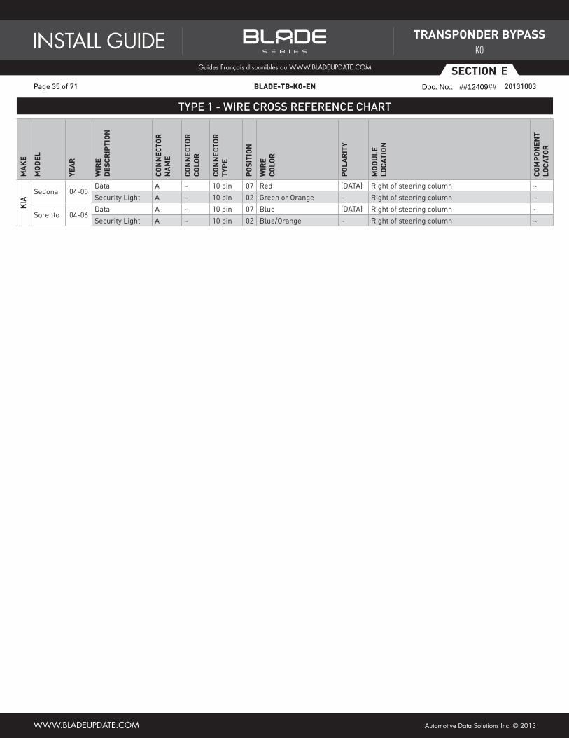
Sedona 04-05Data A ~ 10 pin 07 Red (DATA) Right of steering column ~
Security Light A ~ 10 pin 02 Green or Orange ~ Right of steering column ~
Sorento 04-06Data A ~ 10 pin 07 Blue (DATA) Right of steering column ~
Security Light A ~ 10 pin 02 Blue/Orange ~ Right of steering column ~
Page 35 of 71 BLADE-TB-KO-EN 20131003
INSTALL GUIDEGuides Français disponibles au WWW.bLADEUpDATE.com
WWW.bLADEUpDATE.com Automotive Data Solutions Inc. © 2013
TraNSpONdEr BypaSS
KO
Doc. No.: ##12409##
Page 36
ESECTION
TYPE 1 - WIRING DIAGRAM
10123456789
27
BROWN/RED (NC)BROWN/RED (NC)
BLUE/RED (NC)BLUE/RED (NC)
WHITE/BLACK - SECURITY LIGHT INPUTWHITE/BLACK - SECURITY LIGHT INPUTWHITE/RED - SECURITY LIGHT OUTPUTWHITE/RED - SECURITY LIGHT OUTPUTWHITE (NC)WHITE (NC)YELLOW (NC)YELLOW (NC)
BROWN/YELLOW (NC)BROWN/YELLOW (NC)ORANGE/BLACK - DATAORANGE/BLACK - DATAORANGE/WHITE (NC)ORANGE/WHITE (NC)ORANGE (NC)ORANGE (NC)PINK/BLACK (NC)PINK/BLACK (NC)PINK (NC)PINK (NC)
BLUE/YELLOW (NC)BLUE/YELLOW (NC)GREEN/RED (NC)GREEN/RED (NC)
BLACK (NC)BLACK (NC)
GRAY/RED (NC)GRAY/RED (NC)GRAY/YELLOW (NC)GRAY/YELLOW (NC)
REMOTE STARTER
01
02
03
04
05
06
07
08
09
10
11
12
13
14
15
16
17
18
19
20
GRAY/RED GRAY/YELLOW
BLUE/YELLOW
YELLOWGREEN/RED
BLUE/RED
NO WIREORANGE
ORANGE/WHITEORANGE/BLACK
BROWN/YELLOWBROWN/RED
BLACKNO WIRE
PINKPINK/BLACK
NO WIREWHITE
WHITE/BLACKWHITE/RED
*BLADE CONNECTOR EXACT PIN-OUT
DATA
SECURITY LIGHT
CONNECTOR AAT THE IMMOBILIZER UNIT,
RIGHT SIDE OF THE STEERING COLUMN
Page 36 of 71 BLADE-TB-KO-EN 20131003
INSTALL GUIDEGuides Français disponibles au WWW.bLADEUpDATE.com
WWW.bLADEUpDATE.com Automotive Data Solutions Inc. © 2013
TraNSpONdEr BypaSS
KO
Doc. No.: ##12409##
Page 37
ESECTION
TYPE 2 - WIRE CROSS REFERENCE CHART
Ma
KE
MO
dEL
yEa
r
WIr
Ed
ESC
rIp
TIO
N
CO
NN
ECTO
rN
aM
E
CO
NN
ECTO
rC
OLO
r
CO
NN
ECTO
rTy
pE
pO
SITI
ON
WIr
EC
OLO
r
pO
Lar
ITy
MO
dU
LELO
CaTI
ON
CO
Mp
ON
ENT
LOCa
TOr
HyU
Nd
aI
Tucson V6 05-07Data B ~ 8 pin 06 Brown/Orange (DATA) Right of steering column ~
Security Light B ~ 8 pin 02 White/Black ~ Right of steering column ~
KIa Sportage V6 05-07
Data B ~ 8 pin 06 Brown/Orange (DATA) Left of steering column ~
Security Light B ~ 8 pin 02 White/Black ~ Left of steering column ~
Page 37 of 71 BLADE-TB-KO-EN 20131003
INSTALL GUIDEGuides Français disponibles au WWW.bLADEUpDATE.com
WWW.bLADEUpDATE.com Automotive Data Solutions Inc. © 2013
TraNSpONdEr BypaSS
KO
Doc. No.: ##12409##
Page 38
ESECTION
TYPE 2 - WIRING DIAGRAM
12345678
26
DATASECURIT
Y LIGHT
CONNECTOR BAT IMMOBILIZER
BROWN/RED (NC)BROWN/RED (NC)
BLUE/RED (NC)BLUE/RED (NC)
WHITE/BLACK - SECURITY LIGHT INPUTWHITE/BLACK - SECURITY LIGHT INPUTWHITE/RED - SECURITY LIGHT OUTPUTWHITE/RED - SECURITY LIGHT OUTPUTWHITE (NC)WHITE (NC)YELLOW (NC)YELLOW (NC)
BROWN/YELLOW (NC)BROWN/YELLOW (NC)ORANGE/BLACK - DATAORANGE/BLACK - DATAORANGE/WHITE (NC)ORANGE/WHITE (NC)ORANGE (NC)ORANGE (NC)PINK/BLACK (NC)PINK/BLACK (NC)PINK (NC)PINK (NC)
BLUE/YELLOW (NC)BLUE/YELLOW (NC)GREEN/RED (NC)GREEN/RED (NC)
BLACK (NC)BLACK (NC)
GRAY/RED (NC)GRAY/RED (NC)GRAY/YELLOW (NC)GRAY/YELLOW (NC)
REMOTE STARTER
01
02
03
04
05
06
07
08
09
10
11
12
13
14
15
16
17
18
19
20
GRAY/RED GRAY/YELLOW
BLUE/YELLOW
YELLOWGREEN/RED
BLUE/RED
NO WIREORANGE
ORANGE/WHITEORANGE/BLACK
BROWN/YELLOWBROWN/RED
BLACKNO WIRE
PINKPINK/BLACK
NO WIREWHITE
WHITE/BLACKWHITE/RED
*BLADE CONNECTOR EXACT PIN-OUT
Page 38 of 71 BLADE-TB-KO-EN 20131003
INSTALL GUIDEGuides Français disponibles au WWW.bLADEUpDATE.com
WWW.bLADEUpDATE.com Automotive Data Solutions Inc. © 2013
TraNSpONdEr BypaSS
KO
Doc. No.: ##12409##
Page 39
ESECTION
TYPE 3 - WIRE CROSS REFERENCE CHART
Ma
KE
MO
dEL
yEa
r
WIr
Ed
ESC
rIp
TIO
N
CO
NN
ECTO
rN
aM
E
CO
NN
ECTO
rC
OLO
r
CO
NN
ECTO
rTy
pE
pO
SITI
ON
WIr
EC
OLO
r
pO
Lar
ITy
MO
dU
LELO
CaTI
ON
CO
Mp
ON
ENT
LOCa
TOr
HyU
Nd
aI
Tucson V6 03-06 Data I ~ ~ 20 Blue/Orange (DATA) Behind fuse box - BCM ~
Page 39 of 71 BLADE-TB-KO-EN 20131003
INSTALL GUIDEGuides Français disponibles au WWW.bLADEUpDATE.com
WWW.bLADEUpDATE.com Automotive Data Solutions Inc. © 2013
TraNSpONdEr BypaSS
KO
Doc. No.: ##12409##
Page 40
ESECTION
TYPE 3 - WIRING DIAGRAM
10
11 12 13 14 15 16 17 18 19 20
1 2 3 4 5 6 7 8 9
20
BROWN/RED (NC)BROWN/RED (NC)
BLUE/RED (NC)BLUE/RED (NC)
WHITE/BLACK (NC)WHITE/BLACK (NC)WHITE/RED (NC)WHITE/RED (NC)WHITE (NC)WHITE (NC)YELLOW (NC)YELLOW (NC)
BROWN/YELLOW (NC)BROWN/YELLOW (NC)ORANGE/BLACK - DATAORANGE/BLACK - DATAORANGE/WHITE (NC)ORANGE/WHITE (NC)ORANGE (NC)ORANGE (NC)PINK/BLACK (NC)PINK/BLACK (NC)PINK (NC)PINK (NC)
BLUE/YELLOW (NC)BLUE/YELLOW (NC)GREEN/RED (NC)GREEN/RED (NC)
BLACK (NC)BLACK (NC)
GRAY/RED (NC)GRAY/RED (NC)GRAY/YELLOW (NC)GRAY/YELLOW (NC)
REMOTE STARTER
01
02
03
04
05
06
07
08
09
10
11
12
13
14
15
16
17
18
19
20
GRAY/RED GRAY/YELLOW
BLUE/YELLOW
YELLOWGREEN/RED
BLUE/RED
NO WIREORANGE
ORANGE/WHITEORANGE/BLACK
BROWN/YELLOWBROWN/RED
BLACKNO WIRE
PINKPINK/BLACK
NO WIREWHITE
WHITE/BLACKWHITE/RED
*BLADE CONNECTOR EXACT PIN-OUT
DATACONNECTOR IBEHIND FUSE BOX
FUSE BOX
Page 40 of 71 BLADE-TB-KO-EN 20131003
INSTALL GUIDEGuides Français disponibles au WWW.bLADEUpDATE.com
WWW.bLADEUpDATE.com Automotive Data Solutions Inc. © 2013
TraNSpONdEr BypaSS
KO
Doc. No.: ##12409##
Page 41
ESECTION
TYPE 4 - WIRE CROSS REFERENCE CHART
Ma
KE
MO
dEL
yEa
r
WIr
Ed
ESC
rIp
TIO
N
CO
NN
ECTO
rN
aM
E
CO
NN
ECTO
rC
OLO
r
CO
NN
ECTO
rTy
pE
pO
SITI
ON
WIr
EC
OLO
r
pO
Lar
ITy
MO
dU
LELO
CaTI
ON
CO
Mp
ON
ENT
LOCa
TOr
HyU
Nd
aI
XG300 01Data D ~ 10 pin 08 Green (DATA) Next to OBDII connector ~
Security Light E ~ 20 pin 04 Brown/White or Pink ~ Left of steering column ~
XG350 02-05Data D ~ 10 pin 08 Green (DATA) Next to OBDII connector ~
Security Light E ~ 20 pin 04 Brown/White or Pink ~ Left of steering column ~
Page 41 of 71 BLADE-TB-KO-EN 20131003
INSTALL GUIDEGuides Français disponibles au WWW.bLADEUpDATE.com
WWW.bLADEUpDATE.com Automotive Data Solutions Inc. © 2013
TraNSpONdEr BypaSS
KO
Doc. No.: ##12409##
Page 42
ESECTION
TYPE 4 - WIRING DIAGRAM
54321
109876
1
20 19 18 17 16 15 14 13 12 11
10 9 8 7 6 5 4 3 24
8
BROWN/RED (NC)BROWN/RED (NC)
BLUE/RED (NC)BLUE/RED (NC)
WHITE/BLACK - SECURITY LIGHT INPUTWHITE/BLACK - SECURITY LIGHT INPUTWHITE/RED - SECURITY LIGHT OUTPUTWHITE/RED - SECURITY LIGHT OUTPUTWHITE (NC)WHITE (NC)YELLOW (NC)YELLOW (NC)
BROWN/YELLOW (NC)BROWN/YELLOW (NC)ORANGE/BLACK - DATAORANGE/BLACK - DATAORANGE/WHITE (NC)ORANGE/WHITE (NC)ORANGE (NC)ORANGE (NC)PINK/BLACK (NC)PINK/BLACK (NC)PINK (NC)PINK (NC)
BLUE/YELLOW (NC)BLUE/YELLOW (NC)GREEN/RED (NC)GREEN/RED (NC)
BLACK (NC)BLACK (NC)
GRAY/RED (NC)GRAY/RED (NC)GRAY/YELLOW (NC)GRAY/YELLOW (NC)
REMOTE STARTER
01
02
03
04
05
06
07
08
09
10
11
12
13
14
15
16
17
18
19
20
GRAY/RED GRAY/YELLOW
BLUE/YELLOW
YELLOWGREEN/RED
BLUE/RED
NO WIREORANGE
ORANGE/WHITEORANGE/BLACK
BROWN/YELLOWBROWN/RED
BLACKNO WIRE
PINKPINK/BLACK
NO WIREWHITE
WHITE/BLACKWHITE/RED
*BLADE CONNECTOR EXACT PIN-OUT
DATA
CONNECTOR DUNDER DASH
NEXT TO OBDII CONNECTOR
SECURITY LIGHT
CONNECTOR ELEFT OF STEERING COLUMN
Page 42 of 71 BLADE-TB-KO-EN 20131003
INSTALL GUIDEGuides Français disponibles au WWW.bLADEUpDATE.com
WWW.bLADEUpDATE.com Automotive Data Solutions Inc. © 2013
TraNSpONdEr BypaSS
KO
Doc. No.: ##12409##
Page 43
ESECTION
TYPE 5 - WIRE CROSS REFERENCE CHART
Ma
KE
MO
dEL
yEa
r
WIr
Ed
ESC
rIp
TIO
N
CO
NN
ECTO
rN
aM
E
CO
NN
ECTO
rC
OLO
r
CO
NN
ECTO
rTy
pE
pO
SITI
ON
WIr
EC
OLO
r
pO
Lar
ITy
MO
dU
LELO
CaTI
ON
CO
Mp
ON
ENT
LOCa
TOr
HyU
Nd
aI
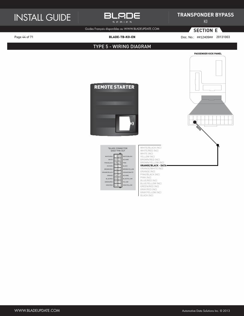
Tucson V6 08-09 Data ~ ~ ~ ~ Brown/Orange (DATA) Passenger kick panel ~
Page 43 of 71 BLADE-TB-KO-EN 20131003
INSTALL GUIDEGuides Français disponibles au WWW.bLADEUpDATE.com
WWW.bLADEUpDATE.com Automotive Data Solutions Inc. © 2013
TraNSpONdEr BypaSS
KO
Doc. No.: ##12409##
Page 44
ESECTION
TYPE 5 - WIRING DIAGRAM
BROWN/RED (NC)BROWN/RED (NC)
BLUE/RED (NC)BLUE/RED (NC)
WHITE/BLACK (NC)WHITE/BLACK (NC)WHITE/RED (NC)WHITE/RED (NC)WHITE (NC)WHITE (NC)YELLOW (NC)YELLOW (NC)
BROWN/YELLOW (NC)BROWN/YELLOW (NC)ORANGE/BLACK - DATAORANGE/BLACK - DATAORANGE/WHITE (NC)ORANGE/WHITE (NC)ORANGE (NC)ORANGE (NC)PINK/BLACK (NC)PINK/BLACK (NC)PINK (NC)PINK (NC)
BLUE/YELLOW (NC)BLUE/YELLOW (NC)GREEN/RED (NC)GREEN/RED (NC)
BLACK (NC)BLACK (NC)
GRAY/RED (NC)GRAY/RED (NC)GRAY/YELLOW (NC)GRAY/YELLOW (NC)
REMOTE STARTER
01
02
03
04
05
06
07
08
09
10
11
12
13
14
15
16
17
18
19
20
GRAY/RED GRAY/YELLOW
BLUE/YELLOW
YELLOWGREEN/RED
BLUE/RED
NO WIREORANGE
ORANGE/WHITEORANGE/BLACK
BROWN/YELLOWBROWN/RED
BLACKNO WIRE
PINKPINK/BLACK
NO WIREWHITE
WHITE/BLACKWHITE/RED
*BLADE CONNECTOR EXACT PIN-OUT
DATA
PASSENGER KICK PANEL
Page 44 of 71 BLADE-TB-KO-EN 20131003
INSTALL GUIDEGuides Français disponibles au WWW.bLADEUpDATE.com
WWW.bLADEUpDATE.com Automotive Data Solutions Inc. © 2013
TraNSpONdEr BypaSS
KO
Doc. No.: ##12409##
Page 45
ESECTION
TYPE 6 - WIRE CROSS REFERENCE CHART
Ma
KE
MO
dEL
yEa
r
WIr
Ed
ESC
rIp
TIO
N
CO
NN
ECTO
rN
aM
E
CO
NN
ECTO
rC
OLO
r
CO
NN
ECTO
rTy
pE
pO
SITI
ON
WIr
EC
OLO
r
pO
Lar
ITy
MO
dU
LELO
CaTI
ON
CO
Mp
ON
ENT
LOCa
TOr
KIa Sportage V6 08-10 Data ~ ~ ~ ~ Brown (DATA) Passenger kick panel ~
Page 45 of 71 BLADE-TB-KO-EN 20131003
INSTALL GUIDEGuides Français disponibles au WWW.bLADEUpDATE.com
WWW.bLADEUpDATE.com Automotive Data Solutions Inc. © 2013
TraNSpONdEr BypaSS
KO
Doc. No.: ##12409##
Page 46
ESECTION
TYPE 6 - WIRING DIAGRAM
BROWN/RED (NC)BROWN/RED (NC)
BLUE/RED (NC)BLUE/RED (NC)
WHITE/BLACK (NC)WHITE/BLACK (NC)WHITE/RED (NC)WHITE/RED (NC)WHITE (NC)WHITE (NC)YELLOW (NC)YELLOW (NC)
BROWN/YELLOW (NC)BROWN/YELLOW (NC)ORANGE/BLACK - DATAORANGE/BLACK - DATAORANGE/WHITE (NC)ORANGE/WHITE (NC)ORANGE (NC)ORANGE (NC)PINK/BLACK (NC)PINK/BLACK (NC)PINK (NC)PINK (NC)
BLUE/YELLOW (NC)BLUE/YELLOW (NC)GREEN/RED (NC)GREEN/RED (NC)
BLACK (NC)BLACK (NC)
GRAY/RED (NC)GRAY/RED (NC)GRAY/YELLOW (NC)GRAY/YELLOW (NC)
REMOTE STARTER
01
02
03
04
05
06
07
08
09
10
11
12
13
14
15
16
17
18
19
20
GRAY/RED GRAY/YELLOW
BLUE/YELLOW
YELLOWGREEN/RED
BLUE/RED
NO WIREORANGE
ORANGE/WHITEORANGE/BLACK
BROWN/YELLOWBROWN/RED
BLACKNO WIRE
PINKPINK/BLACK
NO WIREWHITE
WHITE/BLACKWHITE/RED
*BLADE CONNECTOR EXACT PIN-OUT
DATA
PASSENGER KICK PANEL
Page 46 of 71 BLADE-TB-KO-EN 20131003
INSTALL GUIDEGuides Français disponibles au WWW.bLADEUpDATE.com
WWW.bLADEUpDATE.com Automotive Data Solutions Inc. © 2013
TraNSpONdEr BypaSS
KO
Doc. No.: ##12409##
Page 47
ESECTION
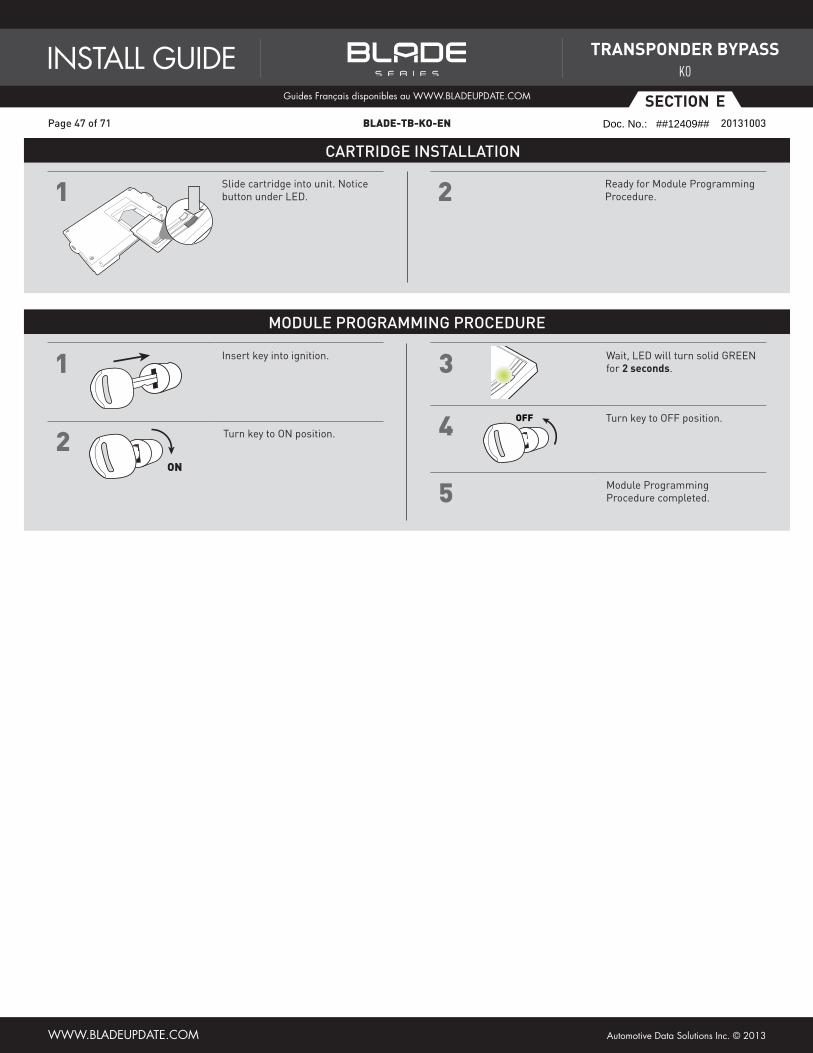
CARTRIDGE INSTALLATION
1 Slide cartridge into unit. Notice button under LED. 2 Ready for Module Programming
Procedure.
MODULE PROGRAMMING PROCEDURE
1 Insert key into ignition.
2 Turn key to ON position.
ON
5 Module Programming Procedure completed.
4 Turn key to OFF position.OFF
3 Wait, LED will turn solid GREEN for 2 seconds.
Page 47 of 71 BLADE-TB-KO-EN 20131003
INSTALL GUIDEGuides Français disponibles au WWW.bLADEUpDATE.com
WWW.bLADEUpDATE.com Automotive Data Solutions Inc. © 2013
TraNSpONdEr BypaSS
KO
Doc. No.: ##12409##
Page 48
FSECTION
INSTALL TYPE SELECTION
XX-XX PAGE X-XADS-TB-TL PAGE 2-3M
aK
E
MO
dEL
yEa
r
INST
aLL
Ty
pE
TOyO
Ta
4Runner 99-02 1
4Runner Regular key 03-10 2
4Runner PTS 10 3
Avalon 98-04 1
Avalon 05-09 2 or 3
Camry 98-02 1
Camry 03-04 1 or 2
Camry 05-06 2
Camry 07-10 2 or 3
Camry Hybrid 07-10 3
Corolla 05-08 2
Corolla 09-10 2 or 3
FJ Cruiser 07-09 2
Hiace 06-09 2
Highlander 01-03 1
Highlander 04-07 2
Highlander 08-10 2 or 3
Highlander Hybrid 06-07 5
Highlander Hybrid 08-10 3
Hilux 04-09 2
Land Cruiser 98-02 1
Land Cruiser 03-07 2
Land Cruiser 08-10 3
Matrix 05-10 2
MR2 Spyder 00-05 1
Prius 04-10 4
RAV4 01-03 1
RAV4 04-08 2
RAV4 09-10 2 or 3
Sequoia 01-07 1
Sequoia 08-10 2
Sienna 99-03 1
Sienna 04-10 2
Solara 99-02 1
Solara 03-04 1 or 2
Solara 05-09 2
Tacoma 05-10 2
Tundra 06 1
Tundra 07-09 2
Venza Regular key only 09 2
Yaris 06-11 2
Ma
KE
MO
dEL
yEa
r
INST
aLL
Ty
pE
LEXU
S
ES 300 98-03 1
ES 330 04-06 2
ES 350 07-08 3
GS 300 98-05 1
GS 300 06 3
GS 350 07-08 3
GS 400 98-00 1
GS 430 01-05 1
GS 430 06-07 3
GS 450 Hybrid 07-08 3
GS 460 08 3
GX 470 03-09 2
IS 250 06-08 3
IS 300 01-05 1
IS 350 06-08 3
IS-F 08 3
LS 400 98-00 1
LS 430 01-03 1
LS 430 04-06 1 or 2
LS 460 07-08 3
LS 600 Hybrid 08 3
LX 470 98-02 1
LX 470 03-07 2
RX 300 99-03 1
RX 330 04-06 2
RX 350 07-09 2
RX 400 Hybrid 06-08 5
SC 300 98-00 1
SC 400 98-00 1
SC 430 02-09 1
pO
NTI
aC
Vibe 08-10 2
SCIO
N tC 05-10 2
xB 08-10 2
xD 08-10 2
NOTEI 1/2 -Type may vary by vehicule equipment
level.2/3 -Type may be standard key or push to start.NC -Not covered
II WARNING: Please advise that the install type numbers have changed since the last revision of this install guide.
III Type 3 install provides simulated tach output for hybrid vehicles.
A hybrid vehicle might be running without its engine being running.To determine whether a hybrid vehicle is running or not, look at the instrument cluster, radio and heating system.
“Push to Start” vehicles have a maximum take over time of 45 seconds:for security reasons, during the remote starter runtime, the driver must press the unlock button of the remote starter fob to trigger a 45 seconds time window which will permit him/her to step into the vehicle and press the brake pedal to complete take over.
Page 48 of 71 BLADE-TB-KO-EN 20131003
INSTALL GUIDEGuides Français disponibles au WWW.bLADEUpDATE.com
WWW.bLADEUpDATE.com Automotive Data Solutions Inc. © 2013
TraNSpONdEr BypaSS
KO
Doc. No.: ##12409##
Page 49
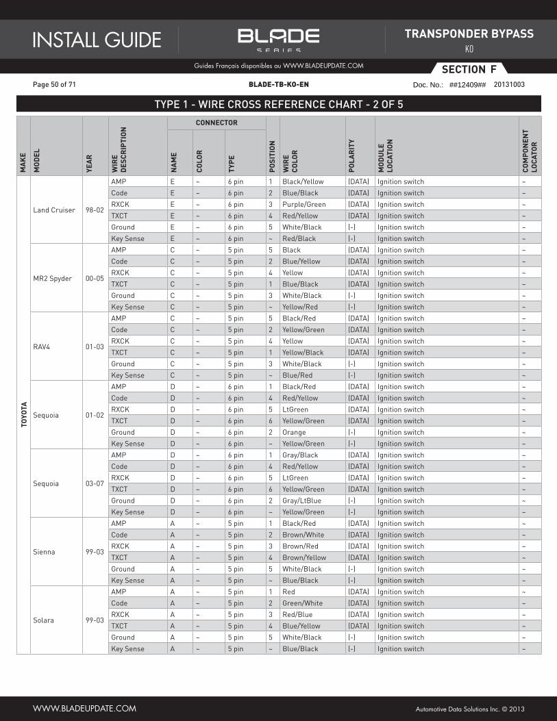
FSECTION
TYPE 1 - WIRE CROSS REFERENCE CHART - 1 OF 5
ADS-TB-TL T1 1-5 PAGE X-XM
aK
E
MO
dEL
yEa
r
WIr
E d
ESC
rIp
TIO
NCONNECTOr
pO
SITI
ON
WIr
E C
OLO
r
pO
Lar
ITy
MO
dU
LE
LOCa
TIO
N
CO
Mp
ON
ENT
LOCa
TOr
Na
ME
CO
LOr
Typ
E
TOyO
Ta
4Runner 99-02
AMP A ~ 5 pin 1 White/Blue (DATA) Ignition switch ~
Code A ~ 5 pin 2 Gray/Red (DATA) Ignition switch ~
RXCK A ~ 5 pin 3 Red/Black (DATA) Ignition switch ~
TXCT A ~ 5 pin 4 Pink/Black (DATA) Ignition switch ~
Ground A ~ 5 pin 5 Brown (-) Ignition switch ~
Key Sense A ~ 5 pin ~ Yellow/Red (-) Ignition switch ~
Avalon 98-99
AMP A ~ 5 pin 1 LtGreen (DATA) Ignition switch ~
Code A ~ 5 pin 2 Black/Red (DATA) Ignition switch ~
RXCK A ~ 5 pin 3 Yellow (DATA) Ignition switch ~
TXCT A ~ 5 pin 4 Green (DATA) Ignition switch ~
Ground A ~ 5 pin 5 White/Black (-) Ignition switch ~
Key Sense A ~ 5 pin ~ Red/Yellow (-) Ignition switch ~
Avalon 00-04
AMP A ~ 5 pin 1 Black/White (DATA) Ignition switch ~
Code A ~ 5 pin 2 Pink/Green (DATA) Ignition switch ~
RXCK A ~ 5 pin 3 Blue/Orange (DATA) Ignition switch ~
TXCT A ~ 5 pin 4 Blue/Yellow (DATA) Ignition switch ~
Ground A ~ 5 pin 5 White/Black (-) Ignition switch ~
Key Sense A ~ 5 pin ~ Red/White (-) Ignition switch ~
Camry 98-01
AMP A ~ 5 pin 1 Black/Yellow (DATA) Ignition switch ~
Code A ~ 5 pin 2 Green/White (DATA) Ignition switch ~
RXCK A ~ 5 pin 3 Red/Blue (DATA) Ignition switch ~
TXCT A ~ 5 pin 4 Blue/Yellow (DATA) Ignition switch ~
Ground A ~ 5 pin 5 White/Black (-) Ignition switch ~
Key Sense A ~ 5 pin ~ Blue/Black (-) Ignition switch ~
Camry (4 cyl) 02-04
AMP B ~ 7 pin 1 Black/Red (DATA) Ignition switch ~
Code B ~ 7 pin 4 Green/White (DATA) Ignition switch ~
RXCK B ~ 7 pin 3 Red/Blue (DATA) Ignition switch ~
TXCT B ~ 7 pin 5 Blue/Yellow (DATA) Ignition switch ~
Ground B ~ 7 pin 7 White/Black (-) Ignition switch ~
Key Sense B ~ 7 pin ~ Blue (-) Ignition switch ~
Camry (6cyl) 02-03
AMP B ~ 7 pin 1 Black/Red (DATA) Ignition switch ~
Code B ~ 7 pin 4 Green/White (DATA) Ignition switch ~
RXCK B ~ 7 pin 3 Red/Blue (DATA) Ignition switch ~
TXCT B ~ 7 pin 5 Blue/Yellow (DATA) Ignition switch ~
Ground B ~ 7 pin 7 White/Black (-) Ignition switch ~
Key Sense B ~ 7 pin ~ Blue (-) Ignition switch ~
Highlander 01-03
AMP B ~ 7 pin 1 White (DATA) Ignition switch ~
Code B ~ 7 pin 4 Gray/Blue (DATA) Ignition switch ~
RXCK B ~ 7 pin 3 Pink (DATA) Ignition switch ~
TXCT B ~ 7 pin 5 Gray (DATA) Ignition switch ~
Ground B ~ 7 pin 7 White/Black (-) Ignition switch ~
Key Sense B ~ 7 pin ~ Blue (-) Ignition switch ~
Page 49 of 71 BLADE-TB-KO-EN 20131003
INSTALL GUIDEGuides Français disponibles au WWW.bLADEUpDATE.com
WWW.bLADEUpDATE.com Automotive Data Solutions Inc. © 2013
TraNSpONdEr BypaSS
KO
Doc. No.: ##12409##
Page 50
FSECTION
TYPE 1 - WIRE CROSS REFERENCE CHART - 2 OF 5
ADS-TB-TL T1 2-5 PAGE X-XM
aK
E
MO
dEL
yEa
r
WIr
E d
ESC
rIp
TIO
NCONNECTOr
pO
SITI
ON
WIr
E C
OLO
r
pO
Lar
ITy
MO
dU
LE
LOCa
TIO
N
CO
Mp
ON
ENT
LOCa
TOr
Na
ME
CO
LOr
Typ
E
TOyO
Ta
Land Cruiser 98-02
AMP E ~ 6 pin 1 Black/Yellow (DATA) Ignition switch ~
Code E ~ 6 pin 2 Blue/Black (DATA) Ignition switch ~
RXCK E ~ 6 pin 3 Purple/Green (DATA) Ignition switch ~
TXCT E ~ 6 pin 4 Red/Yellow (DATA) Ignition switch ~
Ground E ~ 6 pin 5 White/Black (-) Ignition switch ~
Key Sense E ~ 6 pin ~ Red/Black (-) Ignition switch ~
MR2 Spyder 00-05
AMP C ~ 5 pin 5 Black (DATA) Ignition switch ~
Code C ~ 5 pin 2 Blue/Yellow (DATA) Ignition switch ~
RXCK C ~ 5 pin 4 Yellow (DATA) Ignition switch ~
TXCT C ~ 5 pin 1 Blue/Black (DATA) Ignition switch ~
Ground C ~ 5 pin 3 White/Black (-) Ignition switch ~
Key Sense C ~ 5 pin ~ Yellow/Red (-) Ignition switch ~
RAV4 01-03
AMP C ~ 5 pin 5 Black/Red (DATA) Ignition switch ~
Code C ~ 5 pin 2 Yellow/Green (DATA) Ignition switch ~
RXCK C ~ 5 pin 4 Yellow (DATA) Ignition switch ~
TXCT C ~ 5 pin 1 Yellow/Black (DATA) Ignition switch ~
Ground C ~ 5 pin 3 White/Black (-) Ignition switch ~
Key Sense C ~ 5 pin ~ Blue/Red (-) Ignition switch ~
Sequoia 01-02
AMP D ~ 6 pin 1 Black/Red (DATA) Ignition switch ~
Code D ~ 6 pin 4 Red/Yellow (DATA) Ignition switch ~
RXCK D ~ 6 pin 5 LtGreen (DATA) Ignition switch ~
TXCT D ~ 6 pin 6 Yellow/Green (DATA) Ignition switch ~
Ground D ~ 6 pin 2 Orange (-) Ignition switch ~
Key Sense D ~ 6 pin ~ Yellow/Green (-) Ignition switch ~
Sequoia 03-07
AMP D ~ 6 pin 1 Gray/Black (DATA) Ignition switch ~
Code D ~ 6 pin 4 Red/Yellow (DATA) Ignition switch ~
RXCK D ~ 6 pin 5 LtGreen (DATA) Ignition switch ~
TXCT D ~ 6 pin 6 Yellow/Green (DATA) Ignition switch ~
Ground D ~ 6 pin 2 Gray/LtBlue (-) Ignition switch ~
Key Sense D ~ 6 pin ~ Yellow/Green (-) Ignition switch ~
Sienna 99-03
AMP A ~ 5 pin 1 Black/Red (DATA) Ignition switch ~
Code A ~ 5 pin 2 Brown/White (DATA) Ignition switch ~
RXCK A ~ 5 pin 3 Brown/Red (DATA) Ignition switch ~
TXCT A ~ 5 pin 4 Brown/Yellow (DATA) Ignition switch ~
Ground A ~ 5 pin 5 White/Black (-) Ignition switch ~
Key Sense A ~ 5 pin ~ Blue/Black (-) Ignition switch ~
Solara 99-03
AMP A ~ 5 pin 1 Red (DATA) Ignition switch ~
Code A ~ 5 pin 2 Green/White (DATA) Ignition switch ~
RXCK A ~ 5 pin 3 Red/Blue (DATA) Ignition switch ~
TXCT A ~ 5 pin 4 Blue/Yellow (DATA) Ignition switch ~
Ground A ~ 5 pin 5 White/Black (-) Ignition switch ~
Key Sense A ~ 5 pin ~ Blue/Black (-) Ignition switch ~
Page 50 of 71 BLADE-TB-KO-EN 20131003
INSTALL GUIDEGuides Français disponibles au WWW.bLADEUpDATE.com
WWW.bLADEUpDATE.com Automotive Data Solutions Inc. © 2013
TraNSpONdEr BypaSS
KO
Doc. No.: ##12409##
Page 51
FSECTION
XX-XX PAGE X-X
WIRE CROSS REFERENCE CHART
XX-XX PAGE X-X
TYPE 1 - WIRE CROSS REFERENCE CHART - 3 OF 5
ADS-TB-TL T1 3-5 PAGE X-XM
aK
E
MO
dEL
yEa
r
WIr
E d
ESC
rIp
TIO
NCONNECTOr
pO
SITI
ON
WIr
E C
OLO
r
pO
Lar
ITy
MO
dU
LE
LOCa
TIO
N
CO
Mp
ON
ENT
LOCa
TOr
Na
ME
CO
LOr
Typ
E
TOyO
Ta
Tundra S. Cab 06
AMP D ~ 6 pin 1 Red (DATA) Ignition switch ~
Code D ~ 6 pin 3 Green (DATA) Ignition switch ~
RXCK D ~ 6 pin 4 Blue/Red (DATA) Ignition switch ~
TXCT D ~ 6 pin 5 Gray (DATA) Ignition switch ~
Ground D ~ 6 pin 2 Pink (-) Ignition switch ~
Key Sense D ~ 6 pin ~ Pink/Black (-) Ignition switch ~
Tundra D. Cab 06
AMP D ~ 6 pin 1 White (DATA) Ignition switch ~
Code D ~ 6 pin 4 Green (DATA) Ignition switch ~
RXCK D ~ 6 pin 5 Red (DATA) Ignition switch ~
TXCT D ~ 6 pin 6 Black (DATA) Ignition switch ~
Ground D ~ 6 pin 2 Gray (-) Ignition switch ~
Key Sense D ~ 6 pin ~ Yellow/Green (-) Ignition switch ~
LEXU
S
ES300 98-01
AMP A ~ 5 pin 1 Black/Yellow (DATA) Ignition switch ~
Code A ~ 5 pin 2 Green/White (DATA) Ignition switch ~
RXCK A ~ 5 pin 3 Red/Blue (DATA) Ignition switch ~
TXCT A ~ 5 pin 4 Blue/Yellow (DATA) Ignition switch ~
Ground A ~ 5 pin 5 White/Black (-) Ignition switch ~
Key Sense A ~ 5 pin ~ Blue/Black (-) Ignition switch ~
ES300 02-03
AMP B ~ 7 pin 1 Black/Red (DATA) Ignition switch ~
Code B ~ 7 pin 4 Green/White (DATA) Ignition switch ~
RXCK B ~ 7 pin 3 Red/Blue (DATA) Ignition switch ~
TXCT B ~ 7 pin 5 Blue/Yellow (DATA) Ignition switch ~
Ground B ~ 7 pin 7 White/Black (-) Ignition switch ~
Key Sense B ~ 7 pin ~ Blue (-) Ignition switch ~
GS 300 98-00
AMP E ~ 6 pin 1 Black/Red (DATA) Ignition switch ~
Code E ~ 6 pin 2 Green/Black (DATA) Ignition switch ~
RXCK E ~ 6 pin 3 Black/White (DATA) Ignition switch ~
TXCT E ~ 6 pin 4 Blue/Red (DATA) Ignition switch ~
Ground E ~ 6 pin 5 White/Black (-) Ignition switch ~
Key Sense E ~ 6 pin ~ Yellow (-) Ignition switch ~
GS 300 01-05
AMP A ~ 5 pin 1 Black/Red (DATA) Ignition switch ~
Code A ~ 5 pin 2 Green/Black (DATA) Ignition switch ~
RXCK A ~ 5 pin 3 Black/White (DATA) Ignition switch ~
TXCT A ~ 5 pin 4 Blue/Red (DATA) Ignition switch ~
Ground A ~ 5 pin 5 White/Black (-) Ignition switch ~
Key Sense A ~ 5 pin ~ Yellow (-) Ignition switch ~
GS 400 98-00
AMP E ~ 6 pin 1 Black/Red (DATA) Ignition switch ~
Code E ~ 6 pin 2 Green/Black (DATA) Ignition switch ~
RXCK E ~ 6 pin 3 Black/White (DATA) Ignition switch ~
TXCT E ~ 6 pin 4 Blue/Red (DATA) Ignition switch ~
Ground E ~ 6 pin 5 White/Black (-) Ignition switch ~
Key Sense E ~ 6 pin ~ Yellow (-) Ignition switch ~
Page 51 of 71 BLADE-TB-KO-EN 20131003
INSTALL GUIDEGuides Français disponibles au WWW.bLADEUpDATE.com
WWW.bLADEUpDATE.com Automotive Data Solutions Inc. © 2013
TraNSpONdEr BypaSS
KO
Doc. No.: ##12409##
Page 52
FSECTION
TYPE 1 - WIRE CROSS REFERENCE CHART - 4 OF 5
ADS-TB-TL T1 4-5 PAGE X-XM
aK
E
MO
dEL
yEa
r
WIr
E d
ESC
rIp
TIO
NCONNECTOr
pO
SITI
ON
WIr
E C
OLO
r
pO
Lar
ITy
MO
dU
LE
LOCa
TIO
N
CO
Mp
ON
ENT
LOCa
TOr
Na
ME
CO
LOr
Typ
E
LEXU
S
GS 430 01-05
AMP A ~ 5 pin 1 Black/Red (DATA) Ignition switch ~
Code A ~ 5 pin 2 Green/Black (DATA) Ignition switch ~
RXCK A ~ 5 pin 3 Black/White (DATA) Ignition switch ~
TXCT A ~ 5 pin 4 Blue/Red (DATA) Ignition switch ~
Ground A ~ 5 pin 5 White/Black (-) Ignition switch ~
Key Sense A ~ 5 pin ~ Yellow (-) Ignition switch ~
IS 300 01
AMP A ~ 5 pin 1 Black/Red (DATA) Ignition switch ~
Code A ~ 5 pin 2 Green (DATA) Ignition switch ~
RXCK A ~ 5 pin 3 Purple (DATA) Ignition switch ~
TXCT A ~ 5 pin 4 Pink (DATA) Ignition switch ~
Ground A ~ 5 pin 5 White/Black (-) Ignition switch ~
Key Sense A ~ 5 pin ~ Black/Yellow (-) Ignition switch ~
IS 300 02-05
AMP A ~ 5 pin 1 Black/Red (DATA) Ignition switch ~
Code A ~ 5 pin 2 Green/Black (DATA) Ignition switch ~
RXCK A ~ 5 pin 3 Purple (DATA) Ignition switch ~
TXCT A ~ 5 pin 4 Pink/Black (DATA) Ignition switch ~
Ground A ~ 5 pin 5 White/Black (-) Ignition switch ~
Key Sense A ~ 5 pin ~ Black/Yellow (-) Ignition switch ~
LS 400 98-00
AMP A ~ 5 pin 1 White (DATA) Ignition switch ~
Code A ~ 5 pin 2 Red/White (DATA) Ignition switch ~
RXCK A ~ 5 pin 3 Red/Black (DATA) Ignition switch ~
TXCT A ~ 5 pin 4 Red (DATA) Ignition switch ~
Ground A ~ 5 pin 5 White/Black (-) Ignition switch ~
Key Sense A ~ 5 pin ~ Yellow (-) Ignition switch ~
LS 430 01-03
AMP B ~ 7 pin 1 Orange (DATA) Ignition switch ~
Code B ~ 7 pin 4 Red/White (DATA) Ignition switch ~
RXCK B ~ 7 pin 3 White/Red (DATA) Ignition switch ~
TXCT B ~ 7 pin 5 LtBlue/Black (DATA) Ignition switch ~
Ground B ~ 7 pin 7 Violet (-) Ignition switch ~
Key Sense B ~ 7 pin ~ LtGreen/Black (-) Ignition switch ~
LS 430 (smartkey) 04-06
AMP B ~ 7 pin 1 Red (DATA) Ignition switch ~
Code B ~ 7 pin 4 Orange (DATA) Ignition switch ~
RXCK B ~ 7 pin 3 LtBlue (DATA) Ignition switch ~
TXCT B ~ 7 pin 5 Yellow/Black (DATA) Ignition switch ~
Ground B ~ 7 pin 7 Violet (-) Ignition switch ~
Key Sense B ~ 7 pin ~ LtGreen/Black (-) Ignition switch ~
LX 470 98-02
AMP E ~ 6 pin 1 Black/Yellow (DATA) Ignition switch ~
Code E ~ 6 pin 2 Blue/Black (DATA) Ignition switch ~
RXCK E ~ 6 pin 3 Purple/Green (DATA) Ignition switch ~
TXCT E ~ 6 pin 4 Red/Yellow (DATA) Ignition switch ~
Ground E ~ 6 pin 5 White/Black (-) Ignition switch ~
Key Sense E ~ 6 pin ~ Red/White (-) Ignition switch ~
Page 52 of 71 BLADE-TB-KO-EN 20131003
INSTALL GUIDEGuides Français disponibles au WWW.bLADEUpDATE.com
WWW.bLADEUpDATE.com Automotive Data Solutions Inc. © 2013
TraNSpONdEr BypaSS
KO
Doc. No.: ##12409##
Page 53
FSECTION
TYPE 1 - WIRE CROSS REFERENCE CHART - 5 OF 5
ADS-TB-TL T1 5-5 PAGE X-XM
aK
E
MO
dEL
yEa
r
WIr
E d
ESC
rIp
TIO
NCONNECTOr
pO
SITI
ON
WIr
E C
OLO
r
pO
Lar
ITy
MO
dU
LE
LOCa
TIO
N
CO
Mp
ON
ENT
LOCa
TOr
Na
ME
CO
LOr
Typ
E
LEXU
S
RX 300 99
AMP A ~ 5 pin 1 Blue/White (DATA) Ignition switch ~
Code A ~ 5 pin 2 Purple (DATA) Ignition switch ~
RXCK A ~ 5 pin 3 Black (DATA) Ignition switch ~
TXCT A ~ 5 pin 4 Gray (DATA) Ignition switch ~
Ground A ~ 5 pin 5 White/Black (-) Ignition switch ~
Key Sense A ~ 5 pin ~ Blue (-) Ignition switch ~
RX 300 00
AMP A ~ 5 pin 1 Blue/White (DATA) Ignition switch ~
Code A ~ 5 pin 2 Purple (DATA) Ignition switch ~
RXCK A ~ 5 pin 3 Pink (DATA) Ignition switch ~
TXCT A ~ 5 pin 4 Gray (DATA) Ignition switch ~
Ground A ~ 5 pin 5 White/Black (-) Ignition switch ~
Key Sense A ~ 5 pin ~ Blue (-) Ignition switch ~
RX 300 01-03
AMP A ~ 5 pin 1 Black/Red (DATA) Ignition switch ~
Code A ~ 5 pin 2 Purple (DATA) Ignition switch ~
RXCK A ~ 5 pin 3 Pink (DATA) Ignition switch ~
TXCT A ~ 5 pin 4 Gray (DATA) Ignition switch ~
Ground A ~ 5 pin 5 White/Black (-) Ignition switch ~
Key Sense A ~ 5 pin ~ Blue (-) Ignition switch ~
SC 300 98-00
AMP A ~ 5 pin 1 Black/Red (DATA) Ignition switch ~
Code A ~ 5 pin 2 Black/Orange (DATA) Ignition switch ~
RXCK A ~ 5 pin 3 Blue (DATA) Ignition switch ~
TXCT A ~ 5 pin 4 Green/Orange (DATA) Ignition switch ~
Ground A ~ 5 pin 5 White/Green (-) Ignition switch ~
Key Sense A ~ 5 pin ~ Yellow (-) Ignition switch ~
SC 400 98-00
AMP A ~ 5 pin 1 Black/Red (DATA) Ignition switch ~
Code A ~ 5 pin 2 Black/Orange (DATA) Ignition switch ~
RXCK A ~ 5 pin 3 Blue (DATA) Ignition switch ~
TXCT A ~ 5 pin 4 Green/Orange (DATA) Ignition switch ~
Ground A ~ 5 pin 5 White/Green (-) Ignition switch ~
Key Sense A ~ 5 pin ~ Yellow (-) Ignition switch ~
SC 430 02-09
AMP A ~ 5 pin 1 Yellow (DATA) Ignition switch ~
Code A ~ 5 pin 2 Violet/White (DATA) Ignition switch ~
RXCK A ~ 5 pin 3 Red (DATA) Ignition switch ~
TXCT A ~ 5 pin 4 Green (DATA) Ignition switch ~
Ground A ~ 5 pin 5 Violet (-) Ignition switch ~
Key Sense A ~ 5 pin ~ LtGreen/Black (-) Ignition switch ~
Page 53 of 71 BLADE-TB-KO-EN 20131003
INSTALL GUIDEGuides Français disponibles au WWW.bLADEUpDATE.com
WWW.bLADEUpDATE.com Automotive Data Solutions Inc. © 2013
TraNSpONdEr BypaSS
KO
Doc. No.: ##12409##
Page 54
FSECTION
XX-XX PAGE X-X
TYPE 1 - COMPONENT LOCATOR - CONNECTORS
ADS-AL(TB)-TL T1 PAGE X-X
Connector located at immobilizer near key barrel or 8 inches lower on the immobilizer harness.
1
3 4 5 6
2
D
1 2 3 4 5 6
E
1 2 3 4 5
A
1 2 3 4 5 6 7
B
1 2 3 4 5
C
Page 54 of 71 BLADE-TB-KO-EN 20131003
INSTALL GUIDEGuides Français disponibles au WWW.bLADEUpDATE.com
WWW.bLADEUpDATE.com Automotive Data Solutions Inc. © 2013
TraNSpONdEr BypaSS
KO
Doc. No.: ##12409##
Page 55
FSECTION
TYPE 1 - WIRING DIAGRAM
BROWN/RED (NC)BROWN/RED (NC)
BLUE/RED - TXCTBLUE/RED - TXCT
YELLOW (NC)YELLOW (NC)
BROWN/YELLOW (NC)BROWN/YELLOW (NC)ORANGE/BLACK (NC)ORANGE/BLACK (NC)ORANGE/WHITE (NC)ORANGE/WHITE (NC)ORANGE - AMPORANGE - AMPPINK/BLACK - CODE KEY SIDEPINK/BLACK - CODE KEY SIDEPINK - CODE ECM SIDEPINK - CODE ECM SIDE
BLUE/YELLOW (NC)BLUE/YELLOW (NC)GREEN/RED - DATAGREEN/RED - DATA
BLACK (NC)BLACK (NC)
GRAY/RED - RXCK VEHICLE SIDEGRAY/RED - RXCK VEHICLE SIDEGRAY/YELLOW (NC)GRAY/YELLOW (NC)
REMOTE STARTER
01
02
03
04
05
06
07
08
09
10
11
12
13
14
15
16
17
18
19
20
GRAY/RED GRAY/YELLOW
BLUE/YELLOW
YELLOWGREEN/RED
BLUE/RED
NO WIREORANGE
ORANGE/WHITEORANGE/BLACK
BROWN/YELLOWBROWN/RED
BLACKNO WIRE
PINKPINK/BLACK
NO WIREWHITE
WHITE/BLACKWHITE/RED
*BLADE CONNECTOR EXACT PIN-OUT
GROUND WHEN RUNNING (-) OUTPUTGROUND WHEN RUNNING (-) OUTPUT
WHITE/BLACK - RXCK KEY SIDEWHITE/BLACK - RXCK KEY SIDEWHITE/RED - RXCK VEHICLE SIDEWHITE/RED - RXCK VEHICLE SIDEWHITE (NC)WHITE (NC)
CODEAMP
CONNECTIONS MAY VARYACCORDING TO VEHICLE.
REFER TO CHART FOR CONNECTIONDETAILS TO IMMOBILIZER.
KEYSENSE (-)
RXCKTXCT
Page 55 of 71 BLADE-TB-KO-EN 20131003
INSTALL GUIDEGuides Français disponibles au WWW.bLADEUpDATE.com
WWW.bLADEUpDATE.com Automotive Data Solutions Inc. © 2013
TraNSpONdEr BypaSS
KO
Doc. No.: ##12409##
Page 56
FSECTION
TYPE 2 - WIRE CROSS REFERENCE CHART - 1 OF 3
ADS-TB-TL T2 1-3 PAGE X-XM
aK
E
MO
dEL
yEa
r
WIr
E d
ESC
rIp
TIO
NCONNECTOr
pO
SITI
ON
WIr
E C
OLO
r
pO
Lar
ITy
MO
dU
LE
LOCa
TIO
N
CO
Mp
ON
ENT
LOCa
TOr
Na
ME
CO
LOr
Typ
E
TOyO
Ta
4Runner 03-10
Code ~ ~ 7 pin 4 Pink/Green (DATA) Ignition switch ~
TXCT ~ ~ 7 pin 5 LtGreen/Red (DATA) Ignition switch ~
Keysense ~ ~ 7 pin ~ Green/Yellow (-) Ignition switch ~
Avalon 05-09
Code ~ ~ 7 pin 4 LtGreen (DATA) Ignition switch ~
TXCT ~ ~ 7 pin 5 Brown (DATA) Ignition switch ~
Keysense ~ ~ 7 pin ~ Black (-) Ignition switch ~
Camry 03-06
Code ~ ~ 7 pin 4 Green/White (DATA) Ignition switch ~
TXCT ~ ~ 7 pin 5 Blue/Yellow (DATA) Ignition switch ~
Keysense ~ ~ 7 pin ~ Blue (-) Ignition switch ~
Camry 07-10
Code ~ ~ 7 pin 4 Brown (DATA) Ignition switch ~
TXCT ~ ~ 7 pin 5 Red (DATA) Ignition switch ~
Keysense ~ ~ 7 pin ~ Blue (-) Ignition switch ~
Corolla 05-08
Code ~ ~ 7 pin 4 Blue (DATA) Ignition switch ~
TXCT ~ ~ 7 pin 5 Green (DATA) Ignition switch ~
Keysense ~ ~ 7 pin ~ Blue/Black (-) Ignition switch ~
Corolla (Ja-pan) 09-10
Code ~ ~ 7 pin 4 LtBlue (DATA) Ignition switch ~
TXCT ~ ~ 7 pin 5 Beige (DATA) Ignition switch ~
Keysense ~ ~ 7 pin ~ LtBlue (-) Ignition switch ~
Corolla (Canada) 09-10
Code ~ ~ 7 pin 4 Pink (DATA) Ignition switch ~
TXCT ~ ~ 7 pin 5 Green (DATA) Ignition switch ~
Keysense ~ ~ 7 pin ~ LtBlue (-) Ignition switch ~
FJ Cruiser 07-09
Code ~ ~ 7 pin 4 Pink/Green (DATA) Ignition switch ~
TXCT ~ ~ 7 pin 5 LtGreen/Red (DATA) Ignition switch ~
Keysense ~ ~ 7 pin ~ Green/Yellow (-) Ignition switch ~
Hiace 06-09
Code ~ ~ 7 pin 4 Blue (DATA) Ignition switch ~
TXCT ~ ~ 7 pin 5 Yellow (DATA) Ignition switch ~
Keysense ~ ~ 7 pin ~ Yellow/Black (-) Ignition switch ~
Highlander 04-07
Code ~ ~ 7 pin 4 Gray (DATA) Ignition switch ~
TXCT ~ ~ 7 pin 5 White (DATA) Ignition switch ~
Keysense ~ ~ 7 pin ~ Green (-) Ignition switch ~
Highlander 08-10
Code ~ ~ 7 pin 4 Red (DATA) Ignition switch ~
TXCT ~ ~ 7 pin 5 LtBlue (DATA) Ignition switch ~
Keysense ~ ~ 7 pin ~ LtBlue (-) Ignition switch ~
Hilux 04-09
Code ~ ~ 7 pin 4 LtBlue/Yellow (DATA) Ignition switch ~
TXCT ~ ~ 7 pin 5 LtBlue/Black (DATA) Ignition switch ~
Keysense ~ ~ 7 pin ~ Green/Yellow (-) Ignition switch ~
Land Cruiser 03-07
Code ~ ~ 7 pin 4 Blue/Black (DATA) Ignition switch ~
TXCT ~ ~ 7 pin 5 Violet/Green (DATA) Ignition switch ~
Keysense ~ ~ 7 pin ~ Red/Black (-) Ignition switch ~
Matrix 05-08
Code ~ ~ 7 pin 4 Blue (DATA) Ignition switch ~
TXCT ~ ~ 7 pin 5 Green (DATA) Ignition switch ~
Keysense ~ ~ 7 pin ~ Blue/Black (-) Ignition switch ~
Page 56 of 71 BLADE-TB-KO-EN 20131003
INSTALL GUIDEGuides Français disponibles au WWW.bLADEUpDATE.com
WWW.bLADEUpDATE.com Automotive Data Solutions Inc. © 2013
TraNSpONdEr BypaSS
KO
Doc. No.: ##12409##
Page 57
FSECTION
TYPE 2 - WIRE CROSS REFERENCE CHART - 2 OF 3
ADS-TB-TL T2 2-3 PAGE X-XM
aK
E
MO
dEL
yEa
r
WIr
E d
ESC
rIp
TIO
NCONNECTOr
pO
SITI
ON
WIr
E C
OLO
r
pO
Lar
ITy
MO
dU
LE
LOCa
TIO
N
CO
Mp
ON
ENT
LOCa
TOr
Na
ME
CO
LOr
Typ
E
TOyO
Ta
Matrix 09-10
Code ~ ~ 7 pin 4 LtBlue (DATA) Ignition switch ~
TXCT ~ ~ 7 pin 5 Beige (DATA) Ignition switch ~
Keysense ~ ~ 7 pin ~ Blue (-) Ignition switch ~
RAV4 04-05
Code ~ ~ 7 pin 4 Blue/Red (DATA) Ignition switch ~
TXCT ~ ~ 7 pin 5 Pink (DATA) Ignition switch ~
Keysense ~ ~ 7 pin ~ Blue/Red (-) Ignition switch ~
RAV4 06-10
Code ~ ~ 7 pin 4 Pink (DATA) Ignition switch ~
TXCT ~ ~ 7 pin 5 Green (DATA) Ignition switch ~
Keysense ~ ~ 7 pin ~ Blue (-) Ignition switch ~
Sequoia 08-10
Code ~ ~ 7 pin 4 LtGreen (DATA) Ignition switch ~
TXCT ~ ~ 7 pin 5 Blue (DATA) Ignition switch ~
Keysense ~ ~ 7 pin ~ Gray (-) Ignition switch ~
Sienna 04-10
Code ~ ~ 7 pin 4 Yellow (DATA) Ignition switch ~
TXCT ~ ~ 7 pin 5 Yellow/Red (DATA) Ignition switch ~
Keysense ~ ~ 7 pin ~ Blue/Black (-) Ignition switch ~
Solara (Convertible) 04-09
Code ~ ~ 7 pin 4 Green/White (DATA) Ignition switch ~
TXCT ~ ~ 7 pin 5 Blue/Yellow (DATA) Ignition switch ~
Keysense ~ ~ 7 pin ~ Blue (-) Ignition switch ~
Solara (Coupe) 04-09
Code ~ ~ 7 pin 4 Yellow (DATA) Ignition switch ~
TXCT ~ ~ 7 pin 5 Yellow/Red (DATA) Ignition switch ~
Keysense ~ ~ 7 pin ~ Blue (-) Ignition switch ~
Tacoma 05-10
Code ~ ~ 7 pin 4 Pink/Green (DATA) Ignition switch ~
TXCT ~ ~ 7 pin 5 LtGreen/Red (DATA) Ignition switch ~
Keysense ~ ~ 7 pin ~ Green/Black (-) Ignition switch ~
Tundra 07-09
Code ~ ~ 7 pin 4 LtGreen (DATA) Ignition switch ~
TXCT ~ ~ 7 pin 5 Blue (DATA) Ignition switch ~
Keysense ~ ~ 7 pin ~ Gray (-) Ignition switch ~
Venza 09
Code ~ ~ 7 pin 4 LtGreen (DATA) Ignition switch ~
TXCT ~ ~ 7 pin 5 Brown (DATA) Ignition switch ~
Keysense ~ ~ 7 pin ~ Brown (-) Ignition switch ~
Yaris 06-11
Code ~ ~ 7 pin 4 Green (DATA) Ignition switch ~
TXCT ~ ~ 7 pin 5 Violet (DATA) Ignition switch ~
Keysense ~ ~ 7 pin ~ Yellow (-) Ignition switch ~
LEXU
S
ES 330 04-06
Code ~ ~ 7 pin 4 Green/White (DATA) Ignition switch ~
TXCT ~ ~ 7 pin 5 Blue/Yellow (DATA) Ignition switch ~
Keysense ~ ~ 7 pin ~ Blue (-) Ignition switch ~
GX 470 03-09
Code ~ ~ 7 pin 4 Yellow (DATA) Ignition switch ~
TXCT ~ ~ 7 pin 5 Yellow/Black (DATA) Ignition switch ~
Keysense ~ ~ 7 pin ~ Green/Yellow (-) Ignition switch ~
LS 430 04-06
Code ~ ~ 7 pin 4 Red/White (DATA) Ignition switch ~
TXCT ~ ~ 7 pin 5 Blue/Black (DATA) Ignition switch ~
Keysense ~ ~ 7 pin ~ LtGreen/Black (-) Ignition switch ~
Page 57 of 71 BLADE-TB-KO-EN 20131003
INSTALL GUIDEGuides Français disponibles au WWW.bLADEUpDATE.com
WWW.bLADEUpDATE.com Automotive Data Solutions Inc. © 2013
TraNSpONdEr BypaSS
KO
Doc. No.: ##12409##
Page 58
FSECTION
TYPE 2 - WIRE CROSS REFERENCE CHART - 3 OF 3
ADS-TB-TL T2 3-3 PAGE X-XM
aK
E
MO
dEL
yEa
r
WIr
E d
ESC
rIp
TIO
NCONNECTOr
pO
SITI
ON
WIr
E C
OLO
r
pO
Lar
ITy
MO
dU
LE
LOCa
TIO
N
CO
Mp
ON
ENT
LOCa
TOr
Na
ME
CO
LOr
Typ
E
LEXU
S
LX 470 03-07
Code ~ ~ 7 pin 4 Blue/Black (DATA) Ignition switch ~
TXCT ~ ~ 7 pin 5 Violet/Green (DATA) Ignition switch ~
Keysense ~ ~ 7 pin ~ Red/Black (-) Ignition switch ~
RX 330 04-06
Code ~ ~ 7 pin 4 LtGreen (DATA) Ignition switch ~
TXCT ~ ~ 7 pin 5 Brown (DATA) Ignition switch ~
Keysense ~ ~ 7 pin ~ Black (-) Ignition switch ~
RX 350 07-08
Code ~ ~ 7 pin 4 LtGreen (DATA) Ignition switch ~
TXCT ~ ~ 7 pin 5 Brown (DATA) Ignition switch ~
Keysense ~ ~ 7 pin ~ Black (-) Ignition switch ~
pO
NTI
aC Vibe 08
Code ~ ~ 7 pin 4 Blue (DATA) Ignition switch ~
TXCT ~ ~ 7 pin 5 Green (DATA) Ignition switch ~
Keysense ~ ~ 7 pin ~ Blue/Black (-) Ignition switch ~
Vibe 09-10
Code ~ ~ 7 pin 4 LtBlue (DATA) Ignition switch ~
TXCT ~ ~ 7 pin 5 Beige (DATA) Ignition switch ~
Keysense ~ ~ 7 pin ~ Blue (-) Ignition switch ~
SCIO
N
tC 05-10
Code ~ ~ 7 pin 4 Yellow (DATA) Ignition switch ~
TXCT ~ ~ 7 pin 5 Red (DATA) Ignition switch ~
Keysense ~ ~ 7 pin ~ Black (-) Ignition switch ~
xB 08-10
Code ~ ~ 7 pin 4 LtBlue (DATA) Ignition switch ~
TXCT ~ ~ 7 pin 5 Beige (DATA) Ignition switch ~
Keysense ~ ~ 7 pin ~ LtBlue (-) Ignition switch ~
xD 08-10
Code ~ ~ 7 pin 4 Green (DATA) Ignition switch ~
TXCT ~ ~ 7 pin 5 Violet (DATA) Ignition switch ~
Keysense ~ ~ 7 pin ~ Yellow (-) Ignition switch ~
Page 58 of 71 BLADE-TB-KO-EN 20131003
INSTALL GUIDEGuides Français disponibles au WWW.bLADEUpDATE.com
WWW.bLADEUpDATE.com Automotive Data Solutions Inc. © 2013
TraNSpONdEr BypaSS
KO
Doc. No.: ##12409##
Page 59
FSECTION
TYPE 2 - WIRING DIAGRAM
1234567 45
BROWN/RED (NC)BROWN/RED (NC)
BLUE/RED (NC)BLUE/RED (NC)
YELLOW (NC)YELLOW (NC)
BROWN/YELLOW (NC)BROWN/YELLOW (NC)ORANGE/BLACK (NC)ORANGE/BLACK (NC)ORANGE/WHITE (NC)ORANGE/WHITE (NC)ORANGE (NC)ORANGE (NC)PINK/BLACK (NC)PINK/BLACK (NC)PINK (NC)PINK (NC)
BLUE/YELLOW (NC)BLUE/YELLOW (NC)GREEN/RED - CODEGREEN/RED - CODE
BLACK (NC)BLACK (NC)
GRAY/RED - TXCTGRAY/RED - TXCTGRAY/YELLOW (NC)GRAY/YELLOW (NC)
REMOTE STARTER
01
02
03
04
05
06
07
08
09
10
11
12
13
14
15
16
17
18
19
20
GRAY/RED GRAY/YELLOW
BLUE/YELLOW
YELLOWGREEN/RED
BLUE/RED
NO WIREORANGE
ORANGE/WHITEORANGE/BLACK
BROWN/YELLOWBROWN/RED
BLACKNO WIRE
PINKPINK/BLACK
NO WIREWHITE
WHITE/BLACKWHITE/RED
*BLADE CONNECTOR EXACT PIN-OUT
WHITE/BLACK - KEYSENSE (-)WHITE/BLACK - KEYSENSE (-)WHITE/RED (NC)WHITE/RED (NC)WHITE - GROUNDWHITE - GROUND
TXCTCODE
KEYSENSE
Page 59 of 71 BLADE-TB-KO-EN 20131003
INSTALL GUIDEGuides Français disponibles au WWW.bLADEUpDATE.com
WWW.bLADEUpDATE.com Automotive Data Solutions Inc. © 2013
TraNSpONdEr BypaSS
KO
Doc. No.: ##12409##
Page 60
FSECTION
TYPE 3 - WIRE CROSS REFERENCE CHART - 1 OF 3
ADS-TB-TL T3 1-3 PAGE X-XM
aK
E
MO
dEL
yEa
r
WIr
E d
ESC
rIp
TIO
NCONNECTOr
pO
SITI
ON
WIr
E C
OLO
r
pO
Lar
ITy
MO
dU
LE
LOCa
TIO
N
CO
Mp
ON
ENT
LOCa
TOr
Na
ME
CO
LOr
Typ
E
TOyO
Ta
4Runner PTS 10
Code ~ ~ 16 pin 10 Violet (DATA) Push to Start ~
TXCT ~ ~ 16 pin 9 White (DATA) Push to Start ~
Push to Start ~ ~ 16 pin 7 LtGreen (-) Push to Start ~
Ignition A ~ 4 pin 4 White (+) Brake switch above brake pedal ~
12V (Brake) A ~ 4 pin 2 Red (+) Brake switch above brake pedal ~
Brake A ~ 4 pin 1 Violet/Green (+) Brake switch above brake pedal ~
Avalon (smartkey) 05-09
Code ~ ~ 16 pin 10 White (DATA) Push to Start ~
TXCT ~ ~ 16 pin 9 Gray (DATA) Push to Start ~
Push to Start ~ ~ 16 pin 7 Blue (-) Push to Start ~
Ignition A ~ 4 pin 3 Brown (+) Brake switch above brake pedal ~
12V (Brake) A ~ 4 pin 2 Black (+) Brake switch above brake pedal ~
Brake A ~ 4 pin 1 White (+) Brake switch above brake pedal ~
Camry Hybrid 07-10
Code ~ ~ 16 pin 10 White (DATA) Push to Start ~
TXCT ~ ~ 16 pin 9 Gray (DATA) Push to Start ~
Push to Start ~ ~ 16 pin 7 Blue (-) Push to Start ~
Ignition A ~ 4 pin 3 Black (+) Brake switch above brake pedal ~
12V (Brake) A ~ 4 pin 2 Black (+) Brake switch above brake pedal ~
Brake A ~ 4 pin 1 White (+) Brake switch above brake pedal ~
Camry (smartkey) 07-10
Code ~ ~ 16 pin 10 White (DATA) Push to Start ~
TXCT ~ ~ 16 pin 9 Gray (DATA) Push to Start ~
Push to Start ~ ~ 16 pin 7 Blue (-) Push to Start ~
Ignition A ~ 4 pin 3 Black (+) Brake switch above brake pedal ~
12V (Brake) A ~ 4 pin 2 Black (+) Brake switch above brake pedal ~
Brake A ~ 4 pin 1 Blue (+) Brake switch above brake pedal ~
Corolla (smartkey) 09-10
Code ~ ~ 16 pin 10 Green (DATA) Push to Start ~
TXCT ~ ~ 16 pin 9 LtBlue (DATA) Push to Start ~
Push to Start ~ ~ 16 pin 7 White (-) Push to Start ~
Ignition A ~ 4 pin 3 Black (+) Brake switch above brake pedal ~
12V (Brake) A ~ 4 pin 2 White (+) Brake switch above brake pedal ~
Brake A ~ 4 pin 1 Blue (+) Brake switch above brake pedal ~
Highlander (smartkey) 08-10
Code ~ ~ 16 pin 10 Gray (DATA) Push to Start ~
TXCT ~ ~ 16 pin 9 Orange (DATA) Push to Start ~
Push to Start ~ ~ 16 pin 7 Pink (-) Push to Start ~
Ignition A ~ 4 pin 3 White (+) Brake switch above brake pedal ~
12V (Brake) A ~ 4 pin 2 Violet (+) Brake switch above brake pedal ~
Brake A ~ 4 pin 1 Blue (+) Brake switch above brake pedal ~
Highlander Hybrid 08-10
Code ~ ~ 16 pin 10 Gray (DATA) Push to Start ~
TXCT ~ ~ 16 pin 9 Orange (DATA) Push to Start ~
Push to Start ~ ~ 16 pin 7 Pink (-) Push to Start ~
Ignition A ~ 4 pin 3 White (+) Brake switch above brake pedal ~
12V (Brake) A ~ 4 pin 2 Violet (+) Brake switch above brake pedal ~
Brake A ~ 4 pin 1 Blue (+) Brake switch above brake pedal ~
Page 60 of 71 BLADE-TB-KO-EN 20131003
INSTALL GUIDEGuides Français disponibles au WWW.bLADEUpDATE.com
WWW.bLADEUpDATE.com Automotive Data Solutions Inc. © 2013
TraNSpONdEr BypaSS
KO
Doc. No.: ##12409##
Page 61
FSECTION
TYPE 3 - WIRE CROSS REFERENCE CHART - 2 OF 3
ADS-TB-TL T3 2-3 PAGE X-XM
aK
E
MO
dEL
yEa
r
WIr
E d
ESC
rIp
TIO
NCONNECTOr
pO
SITI
ON
WIr
E C
OLO
r
pO
Lar
ITy
MO
dU
LE
LOCa
TIO
N
CO
Mp
ON
ENT
LOCa
TOr
Na
ME
CO
LOr
Typ
E
TOyO
Ta
Land Cruiser 08-10
Code ~ ~ 16 pin 10 Green (DATA) Push to Start ~
TXCT ~ ~ 16 pin 9 LtBlue (DATA) Push to Start ~
Push to Start ~ ~ 16 pin 7 Black (-) Push to Start ~
Ignition B ~ 4 pin 3 Black (+) Brake switch above brake pedal ~
12V (Brake) B ~ 4 pin 2 Blue/Black (+) Brake switch above brake pedal ~
Brake B ~ 4 pin 1 Red (+) Brake switch above brake pedal ~
RAV4(smartkey) 09-10
Code ~ ~ 16 pin 10 White (DATA) Push to Start ~
TXCT ~ ~ 16 pin 9 Blue (DATA) Push to Start ~
Push to Start ~ ~ 16 pin 7 White (-) Push to Start ~
Ignition B ~ 4 pin 4 Black (+) Brake switch above brake pedal ~
12V (Brake) B ~ 4 pin 2 White (+) Brake switch above brake pedal ~
Brake B ~ 4 pin 1 Blue (+) Brake switch above brake pedal ~
LEXU
S
ES 350 07-08
Code ~ ~ 16 pin 10 White (DATA) Push to Start ~
TXCT ~ ~ 16 pin 9 Gray (DATA) Push to Start ~
Push to Start ~ ~ 16 pin 7 Blue (-) Push to Start ~
Ignition A ~ 4 pin 3 Black (+) Brake switch above brake pedal ~
12V (Brake) A ~ 4 pin 2 Black (+) Brake switch above brake pedal ~
Brake A ~ 4 pin 1 Blue (+) Brake switch above brake pedal ~
GS 300 06
Code ~ ~ 16 pin 10 Yellow (DATA) Push to Start ~
TXCT ~ ~ 16 pin 9 Blue (DATA) Push to Start ~
Push to Start ~ ~ 16 pin 7 Pink (-) Push to Start ~
Ignition B ~ 4 pin 3 Black/White (+) Brake switch above brake pedal ~
12V (Brake) A ~ 4 pin 2 Blue/White (+) Brake switch above brake pedal ~
Brake B ~ 4 pin 1 Red/Black (+) Brake switch above brake pedal ~
GS 350 07-08
Code ~ ~ 16 pin 10 Yellow (DATA) Push to Start ~
TXCT ~ ~ 16 pin 9 Blue (DATA) Push to Start ~
Push to Start ~ ~ 16 pin 7 Pink (-) Push to Start ~
Ignition B ~ 4 pin 3 Black/White (+) Brake switch above brake pedal ~
12V (Brake) B ~ 4 pin 2 Blue/White (+) Brake switch above brake pedal ~
Brake B ~ 4 pin 1 Red/Black (+) Brake switch above brake pedal ~
GS 430 06-07
Code ~ ~ 16 pin 10 Yellow (DATA) Push to Start ~
TXCT ~ ~ 16 pin 9 Blue (DATA) Push to Start ~
Push to Start ~ ~ 16 pin 7 Pink (-) Push to Start ~
Ignition B ~ 4 pin 3 Black/White (+) Brake switch above brake pedal ~
12V (Brake) B ~ 4 pin 2 Blue/White (+) Brake switch above brake pedal ~
Brake B ~ 4 pin 1 Red/Black (+) Brake switch above brake pedal ~
GS 450 Hybrid 07-08
Code ~ ~ 16 pin 10 Yellow (DATA) Push to Start ~
TXCT ~ ~ 16 pin 9 Blue (DATA) Push to Start ~
Push to Start ~ ~ 16 pin 7 Pink (-) Push to Start ~
Ignition B ~ 4 pin 3 Black/White (+) Brake switch above brake pedal ~
12V (Brake) B ~ 4 pin 2 Blue/White (+) Brake switch above brake pedal ~
Brake B ~ 4 pin 1 Red/Black (+) Brake switch above brake pedal ~
Page 61 of 71 BLADE-TB-KO-EN 20131003
INSTALL GUIDEGuides Français disponibles au WWW.bLADEUpDATE.com
WWW.bLADEUpDATE.com Automotive Data Solutions Inc. © 2013
TraNSpONdEr BypaSS
KO
Doc. No.: ##12409##
Page 62
FSECTION
TYPE 3 - WIRE CROSS REFERENCE CHART - 3 OF 3
ADS-TB-TL T3 3-3 PAGE X-XM
aK
E
MO
dEL
yEa
r
WIr
E d
ESC
rIp
TIO
NCONNECTOr
pO
SITI
ON
WIr
E C
OLO
r
pO
Lar
ITy
MO
dU
LE
LOCa
TIO
N
CO
Mp
ON
ENT
LOCa
TOr
Na
ME
CO
LOr
Typ
E
LEXU
S
GS 460 08
Code ~ ~ 16 pin 10 Yellow (DATA) Push to Start ~
TXCT ~ ~ 16 pin 9 Blue (DATA) Push to Start ~
Push to Start ~ ~ 16 pin 7 Pink (-) Push to Start ~
Ignition B ~ 4 pin 3 Black/White (+) Brake switch above brake pedal ~
12V (Brake) B ~ 4 pin 2 Blue/White (+) Brake switch above brake pedal ~
Brake B ~ 4 pin 1 Red/Black (+) Brake switch above brake pedal ~
IS 250 06-08
Code ~ ~ 16 pin 10 LtBlue (DATA) Push to Start ~
TXCT ~ ~ 16 pin 9 Blue (DATA) Push to Start ~
Push to Start ~ ~ 16 pin 7 Black (-) Push to Start ~
Ignition B ~ 4 pin 4 LtGreen (+) Brake switch above brake pedal ~
12V (Brake) B ~ 4 pin 2 Blue/White (+) Brake switch above brake pedal ~
Brake B ~ 4 pin 1 Red/Black (+) Brake switch above brake pedal ~
IS 350 06-08
Code ~ ~ 16 pin 10 LtBlue (DATA) Push to Start ~
TXCT ~ ~ 16 pin 9 Blue (DATA) Push to Start ~
Push to Start ~ ~ 16 pin 7 Black (-) Push to Start ~
Ignition B ~ 4 pin 4 LtGreen (+) Brake switch above brake pedal ~
12V (Brake) B ~ 4 pin 2 Blue/White (+) Brake switch above brake pedal ~
Brake B ~ 4 pin 1 Red/Black (+) Brake switch above brake pedal ~
IS-F 08
Code ~ ~ 16 pin 10 LtBlue (DATA) Push to Start ~
TXCT ~ ~ 16 pin 9 Blue (DATA) Push to Start ~
Push to Start ~ ~ 16 pin 7 Black (-) Push to Start ~
Ignition B ~ 4 pin 4 LtGreen (+) Brake switch above brake pedal ~
12V (Brake) B ~ 4 pin 2 Blue/White (+) Brake switch above brake pedal ~
Brake B ~ 4 pin 1 Red/Black (+) Brake switch above brake pedal ~
LS 460 07-08
Code ~ ~ 16 pin 10 White (DATA) Push to Start ~
TXCT ~ ~ 16 pin 9 Orange (DATA) Push to Start ~
Push to Start ~ ~ 16 pin 7 White (-) Push to Start ~
Ignition B ~ 4 pin 3 Red (+) Brake switch above brake pedal ~
12V (Brake) B ~ 4 pin 2 Green (+) Brake switch above brake pedal ~
Brake B ~ 4 pin 1 Blue (+) Brake switch above brake pedal ~
LS 600 Hybrid 08
Code ~ ~ 16 pin 10 White (DATA) Push to Start ~
TXCT ~ ~ 16 pin 9 Orange (DATA) Push to Start ~
Push to Start ~ ~ 16 pin 7 White (-) Push to Start ~
Ignition B ~ 4 pin 4 LtGreen (+) Brake switch above brake pedal ~
12V (Brake) B ~ 4 pin 2 Green (+) Brake switch above brake pedal ~
Brake B ~ 4 pin 1 Red/Black (+) Brake switch above brake pedal ~
Page 62 of 71 BLADE-TB-KO-EN 20131003
INSTALL GUIDEGuides Français disponibles au WWW.bLADEUpDATE.com
WWW.bLADEUpDATE.com Automotive Data Solutions Inc. © 2013
TraNSpONdEr BypaSS
KO
Doc. No.: ##12409##
Page 63
FSECTION
TYPE 3 - WIRING DIAGRAM
3 41 2
1 2 3 4 5 6 78 9 10 11 12 13 14
ENGINESTARTSTOP
79 10
86
30
87
87A85
213
1N4001
DIODE
1N4001
DIODE
BROWN/RED (NC)BROWN/RED (NC)
BLUE/RED (NC)BLUE/RED (NC)
YELLOW (NC)YELLOW (NC)
BROWN/YELLOW (NC)BROWN/YELLOW (NC)ORANGE/BLACK (NC)ORANGE/BLACK (NC)ORANGE/WHITE (NC)ORANGE/WHITE (NC)ORANGE (NC)ORANGE (NC)PINK/BLACK (NC)PINK/BLACK (NC)PINK (NC)PINK (NC)
BLUE/YELLOW - PTS (-) OUTPUTBLUE/YELLOW - PTS (-) OUTPUTGREEN/RED - CODEGREEN/RED - CODE
BLACK (NC)BLACK (NC)
GRAY/RED - TXCTGRAY/RED - TXCTGRAY/YELLOW (NC)GRAY/YELLOW (NC)
NOTE: FACTORY KEYFOBWILL NOT FUNCTION
WHEN REMOTE STARTERIS ENGAGED.
FOR AFTERMARKETKEYFOB FUNCTIONALITY,
HARDWIRE REMOTESTARTER DOORLOCKSAND ALARM OUTPUTS.
REQUIRED:1X RELAY
AND1X DIODE
BRAKE (+) INPUTBRAKE (+) INPUTIGNITION (+) OUTPUTIGNITION (+) OUTPUT
WHITE/BLACKWHITE/BLACKWHITE/RED (NC)WHITE/RED (NC)WHITE - GROUNDWHITE - GROUND
12V (+)
CODE
PTS (-)TXCT
BRAKE SWITCH
IGNITION
WARNINGIGNITION IS USED ONLY AS AN
INPUT TO THE REMOTE STARTER,NOT AN OUTPUT TO THE VEHICULE.
DIODE CATHODE NEEDS TO BEFACING THE REMOTE STARTER.
WIREAT BRAKE PEDAL
WARNINGDO NOT CONNECT ANY OTHER
ACCESSORY, IGNITION OR START WIREFROM THE REMOTE STARTER TO THEVEHICLE. THE INTERFACE MODULE
IS HANDLING THE REQUIRED VEHICLEPOWER AND START SEQUENCE FROM
THE PUSH TO START BUTTON CIRCUIT.
BRAKE SWITCHLOCATED ABOVE BRAKE PEDAL
REMOTE STARTER
01
02
03
04
05
06
07
08
09
10
11
12
13
14
15
16
17
18
19
20
GRAY/RED GRAY/YELLOW
BLUE/YELLOW
YELLOWGREEN/RED
BLUE/RED
NO WIREORANGE
ORANGE/WHITEORANGE/BLACK
BROWN/YELLOWBROWN/RED
BLACKNO WIRE
PINKPINK/BLACK
NO WIREWHITE
WHITE/BLACKWHITE/RED
*BLADE CONNECTOR EXACT PIN-OUT
Page 63 of 71 BLADE-TB-KO-EN 20131003
INSTALL GUIDEGuides Français disponibles au WWW.bLADEUpDATE.com
WWW.bLADEUpDATE.com Automotive Data Solutions Inc. © 2013
TraNSpONdEr BypaSS
KO
Doc. No.: ##12409##
Page 64
FSECTION
TYPE 4 - WIRE CROSS REFERENCE CHART
ADS-TB-TL T4 PAGE X-XM
aK
E
MO
dEL
yEa
r
WIr
E d
ESC
rIp
TIO
N
CONNECTOr
pO
SITI
ON
WIr
E C
OLO
r
pO
Lar
ITy
MO
dU
LE
LOCa
TIO
N
CO
Mp
ON
ENT
LOCa
TOr
Na
ME
CO
LOr
Typ
E
TOyO
Ta
Prius 04-10
Code ~ ~ 7 pin 4 Blue (DATA) At Key Port ~
TXCT ~ ~ 7 pin 5 LtGreen (DATA) At Key Port ~
Push to Start ~ ~ 8 pin 7 Yellow (-) At Start Button ~
Ignition A ~ 4 pin 3 Orange (+) Above Brake Pedal ~
12V (Brake) A ~ 4 pin 2 Black (+) Above Brake Pedal ~
Brake A ~ 4 pin 1 Blue (+) Above Brake Pedal ~
Page 64 of 71 BLADE-TB-KO-EN 20131003
INSTALL GUIDEGuides Français disponibles au WWW.bLADEUpDATE.com
WWW.bLADEUpDATE.com Automotive Data Solutions Inc. © 2013
TraNSpONdEr BypaSS
KO
Doc. No.: ##12409##
Page 65
FSECTION
TYPE 4 - WIRING DIAGRAM
1234567
8 7 6 5 3 2 14
5 4 3 2 186
30
87
87A85
ENGINESTARTSTOP
7
5 345
3 41 2
86
30
87
87A85
213
1N4001
DIODE
1N4001
DIODE
1N4001
DIODE
1N4001
DIODE
BROWN/RED (NC)BROWN/RED (NC)
BLUE/RED (NC)BLUE/RED (NC)
YELLOW (NC)YELLOW (NC)
BROWN/YELLOW (NC)BROWN/YELLOW (NC)ORANGE/BLACK (NC)ORANGE/BLACK (NC)ORANGE/WHITE (NC)ORANGE/WHITE (NC)ORANGE (NC)ORANGE (NC)PINK/BLACK (NC)PINK/BLACK (NC)PINK (NC)PINK (NC)
BLUE/YELLOW - PTS (-)BLUE/YELLOW - PTS (-)GREEN/RED - CODEGREEN/RED - CODE
BLACK (NC)BLACK (NC)
GRAY/RED - TXCTGRAY/RED - TXCTGRAY/YELLOW (NC)GRAY/YELLOW (NC)
REQUIRED:2X RELAYS
AND3X DIODES
BRAKE (+)BRAKE (+)IGNITION (+) INPUTIGNITION (+) INPUTGROUND WHEN RUNNING (-) OUTPUTGROUND WHEN RUNNING (-) OUTPUT
WHITE/BLACKWHITE/BLACKWHITE/RED (NC)WHITE/RED (NC)WHITE - GROUNDWHITE - GROUND
WARNINGDO NOT CONNECT ANY OTHER
ACCESSORY, IGNITION OR START WIREFROM THE REMOTE STARTER TO THEVEHICLE. THE INTERFACE MODULE
IS HANDLING THE REQUIRED VEHICLEPOWER AND START SEQUENCE FROM
THE PUSH TO START BUTTON CIRCUIT.
12V (+)
NOTE: FACTORY KEYFOBWILL NOT FUNCTION
WHEN REMOTE STARTERIS ENGAGED.
FOR AFTERMARKETKEYFOB FUNCTIONALITY,
HARDWIRE REMOTESTARTER DOORLOCKSAND ALARM OUTPUTS.
KEYPORT
TXCTCODE
BLUE - KEYSENSE (-)
PINK - KEY LOCK
SOLENOID (+)
BRAKE SWITCHLOCATED ABOVE BRAKE PEDAL
12V (+)BRAKE SWITCH
IGNITION
WARNINGIGNITION IS USED ONLY AS AN
INPUT TO THE REMOTE STARTER,NOT AN OUTPUT TO THE VEHICULE.
DIODE CATHODE NEEDS TO BEFACING THE REMOTE STARTER.
WIREAT BRAKE PEDAL
PTS (-)
REMOTE STARTER
01
02
03
04
05
06
07
08
09
10
11
12
13
14
15
16
17
18
19
20
GRAY/RED GRAY/YELLOW
BLUE/YELLOW
YELLOWGREEN/RED
BLUE/RED
NO WIREORANGE
ORANGE/WHITEORANGE/BLACK
BROWN/YELLOWBROWN/RED
BLACKNO WIRE
PINKPINK/BLACK
NO WIREWHITE
WHITE/BLACKWHITE/RED
*BLADE CONNECTOR EXACT PIN-OUT
Page 65 of 71 BLADE-TB-KO-EN 20131003
INSTALL GUIDEGuides Français disponibles au WWW.bLADEUpDATE.com
WWW.bLADEUpDATE.com Automotive Data Solutions Inc. © 2013
TraNSpONdEr BypaSS
KO
Doc. No.: ##12409##
Page 66
FSECTION
TYPE 5 - WIRE CROSS REFERENCE CHART
ADS-TB-TL T5 PAGE X-XM
aK
E
MO
dEL
yEa
r
WIr
E d
ESC
rIp
TIO
N
CONNECTOr
pO
SITI
ON
WIr
E C
OLO
r
pO
Lar
ITy
MO
dU
LE
LOCa
TIO
N
CO
Mp
ON
ENT
LOCa
TOr
Na
ME
CO
LOr
Typ
E
TOyO
Ta
Highlander Hybrid 06-07
Code ~ ~ 7 pin 4 Gray (DATA) Ignition switch ~
TXCT ~ ~ 7 pin 5 LtBlue (DATA) Ignition switch ~
Keysense ~ ~ ~ ~ Green (-) Ignition switch ~
Accessory C ~ 8 pin 4 Green (+) Ignition switch ~
LEXU
S
RX 400 Hybrid 06-08
Code ~ ~ 7 pin 4 LtGreen (DATA) Ignition switch ~
TXCT ~ ~ 7 pin 5 Brown (DATA) Ignition switch ~
Keysense ~ ~ ~ ~ Black (-) Ignition switch ~
Accessory C ~ 8 pin 4 Green (+) Ignition switch ~
Page 66 of 71 BLADE-TB-KO-EN 20131003
INSTALL GUIDEGuides Français disponibles au WWW.bLADEUpDATE.com
WWW.bLADEUpDATE.com Automotive Data Solutions Inc. © 2013
TraNSpONdEr BypaSS
KO
Doc. No.: ##12409##
Page 67
FSECTION
TYPE 5 - WIRING DIAGRAM
1234567 45
BROWN/RED (NC)BROWN/RED (NC)
BLUE/RED (NC)BLUE/RED (NC)
YELLOW (NC)YELLOW (NC)
BROWN/YELLOW (NC)BROWN/YELLOW (NC)ORANGE/BLACK - GROUNDORANGE/BLACK - GROUNDORANGE/WHITE (NC)ORANGE/WHITE (NC)ORANGE (NC)ORANGE (NC)PINK/BLACK (NC)PINK/BLACK (NC)PINK (NC)PINK (NC)
BLUE/YELLOW (NC)BLUE/YELLOW (NC)GREEN/RED - CODEGREEN/RED - CODE
BLACK (NC)BLACK (NC)
GRAY/RED - TXCTGRAY/RED - TXCTGRAY/YELLOW (NC)GRAY/YELLOW (NC)
WHITE/BLACK - KEYSENSE (-)WHITE/BLACK - KEYSENSE (-)WHITE/RED (NC)WHITE/RED (NC)WHITE - GROUNDWHITE - GROUND
TXCTCODE
KEYSENSE (-)
REMOTE STARTER
01
02
03
04
05
06
07
08
09
10
11
12
13
14
15
16
17
18
19
20
GRAY/RED GRAY/YELLOW
BLUE/YELLOW
YELLOWGREEN/RED
BLUE/RED
NO WIREORANGE
ORANGE/WHITEORANGE/BLACK
BROWN/YELLOWBROWN/RED
BLACKNO WIRE
PINKPINK/BLACK
NO WIREWHITE
WHITE/BLACKWHITE/RED
*BLADE CONNECTOR EXACT PIN-OUT
Page 67 of 71 BLADE-TB-KO-EN 20131003
INSTALL GUIDEGuides Français disponibles au WWW.bLADEUpDATE.com
WWW.bLADEUpDATE.com Automotive Data Solutions Inc. © 2013
TraNSpONdEr BypaSS
KO
Doc. No.: ##12409##
Page 68
FSECTION
XX-XX PAGE X-XBLADE-TB-TL PAGE X-XBLADE-TB-TL 18
CARTRIDGE INSTALLATION
2 Ready for Module Programming Procedure.1 Slide cartridge into unit. Notice
button under LED.
3 Wait, LED will turn solid GREEN for 2 seconds.
2 LED will fl ash GREEN and RED.
TYPE 1, 2 & 5 - MODULE PROGRAMMING PROCEDURE - REGULAR KEY
5 Module Programming Procedure completed.
1 Insert key into ignition.
(OR insert key into keyport) 4 Remove key.
(OR remove key from keyport)
Page 68 of 71 BLADE-TB-KO-EN 20131003
INSTALL GUIDEGuides Français disponibles au WWW.bLADEUpDATE.com
WWW.bLADEUpDATE.com Automotive Data Solutions Inc. © 2013
TraNSpONdEr BypaSS
KO
Doc. No.: ##12409##
Page 69
FSECTION
XX-XX PAGE X-XBLADE-TB-TL PAGE 1-1
TYPE 3 - MODULE PROGRAMMING PROCEDURE - SMARTKEY PUSH TO START
8 Module Programming Procedure completed.
7 Wait, LED will turn solid GREEN for 2 seconds.
6 LED will fl ash GREEN and RED.
1 Open key fob.
2 Remove circuit board from key fob.
3 Remove battery from circuit board.
4 Place circuit board in front of push to start button.
ENGINESTARTSTOP
5 Push start button twice [2x] to ON position.
ENGINESTARTSTOP x2
NOTEI When programming, only one key fob will be used. The other
one must be located at least 10 feet away from the vehicle.
TYPE 4 - MODULE PROGRAMMING PROCEDURE - NON-RFID PUSH TO START
5 Module Programming Procedure completed.
4 Wait, LED will turn solid GREEN for 2 seconds.
3 LED will fl ash GREEN and RED.
2 Push start button twice [2x] to ON position.
ENGINESTARTSTOP x2
NOTEI When programming, only one key fob will be used. The other
one must be located at least 10 feet away from the vehicle.
1 Insert keyfob in keyport.ENGINESTARTSTOP
Page 69 of 71 BLADE-TB-KO-EN 20131003
INSTALL GUIDEGuides Français disponibles au WWW.bLADEUpDATE.com
WWW.bLADEUpDATE.com Automotive Data Solutions Inc. © 2013
TraNSpONdEr BypaSS
KO
Doc. No.: ##12409##
Page 70
FSECTION
XX-XX PAGE X-X
NOTICE
XX-XX PAGE X-XVEHICLE OWNER NOTICE
PUSH TO START VEHICLE TAKE OVER PROCEDURE - TO THE VEHICLE OWNER
NOTEI This procedure is to be followed during remote starter runtime
prior to entering vehicle.
II Do not attempt to remote start the vehicle when the OEM RFIDFOB’s are in the vehicle.
! Failure to follow procedure within time restriction will result in vehicle engine shutdown.
3 Push to Start vehicle take over procedure completed.
1 Press UNLOCK on after-market remote.
2 TIME RESTRICTINWithin 45 SECONDS from previous step:
Open vehicle door.
Enter vehicle.
Close vehicle door.
Press and release BRAKE pedal.
VEHICLE OWNER NOTICE
TIME RESTRICTIN COMING UP !
Page 70 of 71 BLADE-TB-KO-EN 20131003
INSTALL GUIDEGuides Français disponibles au WWW.bLADEUpDATE.com
WWW.bLADEUpDATE.com Automotive Data Solutions Inc. © 2013
TraNSpONdEr BypaSS
KO
Doc. No.: ##12409##
Page 71
!SECTION
BLADE-TB PAGE 1-1
LEd STaTUSdIaGNOSTICS
dUrING prOGraMMING dUrING rEMOTE STarT WITH IGNITION OFF
Flashing RED Missing/wrong information from fi rmware or vehicle Incorrectly programmed Incorrectly programmed or connected
Solid RED Waiting for more vehicle information Incorrectly programmed Not programmed waiting for more vehicle information
Flashing GREEN Additional steps required to complete programming
Correctly programmed and operational
False ground when running status from remote starter
Solid GREEN then OFF Correctly programmed Reset in progress Reset in progress
OFF No activity or already programmed Invalid ground when running status from remote starter
At rest and ready for a remote start sequence
MODULE DIAGNOSTICS
IDENTIFY VEHICLE YEAR
1 Locate the Vehicle Identifi cation Number (VIN) and identify the 10th character.
2 Match the VIN’s 10th character to its corresponding year.
L > 1990 S > 1995 y > 2000 5 > 2005 a > 2010
M > 1991 T > 1996 1 > 2001 6 > 2006 B > 2011
N > 1992 V > 1997 2 > 2002 7 > 2007 C > 2012
p > 1993 W > 1998 3 > 2003 8 > 2008 d > 2013
r > 1994 X > 1999 4 > 2004 9 > 2009 E > 2014
4 Y 1 N53 A 5 T A L 8 D 5 R 0 X
FACTORY RESET PROCEDURE
5 RECONNECT all connectors. Repeat programming procedure.
! Failure to follow procedure may result with a DTC or a CHECK ENGINE error message.
1 DISCONNECT cartridge fromremote starter.
2 PRESS AND HOLD programming button while re-connecting cartridge to remote starter.
3 LED will fl ash red. Immediately RELEASE programming button.
4 LED will turn solid red for 2 seconds.
RESET COMPLETED.
Page 71 of 71 BLADE-TB-KO-EN 20131003
INSTALL GUIDEGuides Français disponibles au WWW.bLADEUpDATE.com
WWW.bLADEUpDATE.com Automotive Data Solutions Inc. © 2013
TraNSpONdEr BypaSS
KO
Doc. No.: ##12409##