Automotive Radar and Communications Sharing of the 79-GHz Band You Han and Eylem Ekici Ohio State University, USA [email protected][email protected]Haris Kremo * CONNECT Centre Trinity College, Dublin, Ireland [email protected]Onur Altintas Toyota InfoTechnology Center, USA, Inc. [email protected]ABSTRACT The spectrum scarcity problem is becoming severer in the 5.9 GHz Dedicated Short Range Communication (DSRC) band due to the rapidly increasing wireless traffic demands in vehicular networks. Meanwhile, massive bandwidth has been allocated to automotive radars in the 79 GHz band. Given its large bandwidth, radar imaging accuracy in the 79 GHz automotive radar band is still low because sequen- tial target observations of a single radar sensor are highly correlated. Therefore, the 79 GHz band can be regarded as underutilized. Since the observations of different vehi- cles are less correlated, collaborative radar imaging among neighboring vehicles through vehicle-to-vehicle (V2V) com- munications can improve the accuracy of automotive radar imaging. More importantly, in the resulting Joint Automo- tive Radar-Communication (JARC) system, less bandwidth is required to achieve high radar imaging accuracy. Hence, remaining bandwidth can be utilized to alleviate the spec- trum scarcity problem in the DSRC band. In this paper, we develop a distributed JARC system to facilitate the spectrum sharing between radar imaging and V2V communications in the 79 GHz millimeter wave band. In particular, we implement the proposed JARC system by devising of a corresponding MAC layer protocol, which con- tributes to the future standardization of the JARC system. Moreover, the performance of the proposed JARC system is evaluated through simulation examples, which demonstrates that the JARC system is able to support high-throughput V2V communications in the 79 GHz band. CCS Concepts •Networks → Network protocol design; Link-layer protocols; Network simulations; Mobile ad hoc net- works; * Dr. Haris Kremo was with Toyota InfoTechnology Center when this work was performed. Permission to make digital or hard copies of all or part of this work for personal or classroom use is granted without fee provided that copies are not made or distributed for profit or commercial advantage and that copies bear this notice and the full cita- tion on the first page. Copyrights for components of this work owned by others than ACM must be honored. Abstracting with credit is permitted. To copy otherwise, or re- publish, to post on servers or to redistribute to lists, requires prior specific permission and/or a fee. Request permissions from [email protected]. CarSys’16, October 03-07, 2016, New York City, NY, USA c 2016 ACM. ISBN 978-1-4503-4250-6/16/10. . . $15.00 DOI: http://dx.doi.org/10.1145/2980100.2980106 Keywords Joint automotive radar and communication system; spec- trum sharing; 79 GHz millimeter wave band 1. INTRODUCTION Tens of megahertz bandwidth in the 5.9 GHz band have been allocated to vehicle-to-vehicle (V2V) and vehicle-to- infrastructure (V2I) communications in many countries. This band is also named the Dedicated Short-Range Communi- cations (DSRC) band supporting intelligent transportation systems in the United States. However, many studies have shown that the DSRC band is insufficient to guarantee reli- able transmissions of safety messages [8, 12, 14]. In particu- lar, transmissions of non-safety related messages have to be severely restricted to guarantee the reliable transmissions of safety messages. For example, it is shown in [28] that less than 10% of the DSRC bandwidth remains for non-safety applications if 95% reliability of transmissions is guaranteed for safety applications at medium vehicle density. Meanwhile, the 77 - 81 GHz millimeter wave band has been allocated to automotive radar imaging in many coun- tries as well as at the International Telecommunication Union World Radiocommunication Conference[1], which is also re- ferred to as the 79 GHz band. Despite the width of 4 GHz bandwidth, the accuracy of automotive radar imaging is still low due to temporal correlation between sequential target observations of a single radar sensor [4, 19]. Therefore, the 79 GHz band can be regarded as underutilized. Since the observations of different vehicles are less correlated, collab- orative radar imaging among neighboring vehicles through the exchange of radar imaging results can improve the imag- ing accuracy. More importantly, since fewer observations are required to achieve high imaging accuracy in the resulting Joint Automotive Radar and Communication (JARC) sys- tem [13, 26], the remaining time can be utilized to alleviate the spectrum scarcity problem in the DSRC band. In par- ticular, based on estimation theory, it is shown in [13] that V2V communications can improve radar imaging accuracy. Moreover, a resource allocation scheme is developed in [13] to maximize the remaining time for other communications after the baseline imaging accuracy of vehicles is achieved. Although the JARC system has been studied in some ex- isting works, most of them focus on the development of hard- ware platform [10, 20] and PHY layer issues [5, 9, 11, 23, 26]. For example, a software-defined radio platform is developed in [20], which allows users to implement real-time adaptive radar imaging algorithms using wideband digital communi- cation signals. In [10], another software-defined platform is 6
Transcript
Automotive Radar and Communications Sharing of the79-GHz Band
ABSTRACTThe spectrum scarcity problem is becoming severer in the5.9 GHz Dedicated Short Range Communication (DSRC)band due to the rapidly increasing wireless traffic demandsin vehicular networks. Meanwhile, massive bandwidth hasbeen allocated to automotive radars in the 79 GHz band.Given its large bandwidth, radar imaging accuracy in the79 GHz automotive radar band is still low because sequen-tial target observations of a single radar sensor are highlycorrelated. Therefore, the 79 GHz band can be regardedas underutilized. Since the observations of different vehi-cles are less correlated, collaborative radar imaging amongneighboring vehicles through vehicle-to-vehicle (V2V) com-munications can improve the accuracy of automotive radarimaging. More importantly, in the resulting Joint Automo-tive Radar-Communication (JARC) system, less bandwidthis required to achieve high radar imaging accuracy. Hence,remaining bandwidth can be utilized to alleviate the spec-trum scarcity problem in the DSRC band.
In this paper, we develop a distributed JARC system tofacilitate the spectrum sharing between radar imaging andV2V communications in the 79 GHz millimeter wave band.In particular, we implement the proposed JARC system bydevising of a corresponding MAC layer protocol, which con-tributes to the future standardization of the JARC system.Moreover, the performance of the proposed JARC system isevaluated through simulation examples, which demonstratesthat the JARC system is able to support high-throughputV2V communications in the 79 GHz band.
CCS Concepts•Networks → Network protocol design; Link-layerprotocols; Network simulations; Mobile ad hoc net-works;
∗Dr. Haris Kremo was with Toyota InfoTechnology Centerwhen this work was performed.
Permission to make digital or hard copies of all or part of this work for personal orclassroom use is granted without fee provided that copies are not made or distributedfor profit or commercial advantage and that copies bear this notice and the full cita-tion on the first page. Copyrights for components of this work owned by others thanACM must be honored. Abstracting with credit is permitted. To copy otherwise, or re-publish, to post on servers or to redistribute to lists, requires prior specific permissionand/or a fee. Request permissions from [email protected].
KeywordsJoint automotive radar and communication system; spec-trum sharing; 79 GHz millimeter wave band
1. INTRODUCTIONTens of megahertz bandwidth in the 5.9 GHz band have
been allocated to vehicle-to-vehicle (V2V) and vehicle-to-infrastructure (V2I) communications in many countries. Thisband is also named the Dedicated Short-Range Communi-cations (DSRC) band supporting intelligent transportationsystems in the United States. However, many studies haveshown that the DSRC band is insufficient to guarantee reli-able transmissions of safety messages [8, 12, 14]. In particu-lar, transmissions of non-safety related messages have to beseverely restricted to guarantee the reliable transmissions ofsafety messages. For example, it is shown in [28] that lessthan 10% of the DSRC bandwidth remains for non-safetyapplications if 95% reliability of transmissions is guaranteedfor safety applications at medium vehicle density.
Meanwhile, the 77 - 81 GHz millimeter wave band hasbeen allocated to automotive radar imaging in many coun-tries as well as at the International Telecommunication UnionWorld Radiocommunication Conference[1], which is also re-ferred to as the 79 GHz band. Despite the width of 4 GHzbandwidth, the accuracy of automotive radar imaging is stilllow due to temporal correlation between sequential targetobservations of a single radar sensor [4, 19]. Therefore, the79 GHz band can be regarded as underutilized. Since theobservations of different vehicles are less correlated, collab-orative radar imaging among neighboring vehicles throughthe exchange of radar imaging results can improve the imag-ing accuracy. More importantly, since fewer observations arerequired to achieve high imaging accuracy in the resultingJoint Automotive Radar and Communication (JARC) sys-tem [13, 26], the remaining time can be utilized to alleviatethe spectrum scarcity problem in the DSRC band. In par-ticular, based on estimation theory, it is shown in [13] thatV2V communications can improve radar imaging accuracy.Moreover, a resource allocation scheme is developed in [13]to maximize the remaining time for other communicationsafter the baseline imaging accuracy of vehicles is achieved.
Although the JARC system has been studied in some ex-isting works, most of them focus on the development of hard-ware platform [10, 20] and PHY layer issues [5, 9, 11, 23, 26].For example, a software-defined radio platform is developedin [20], which allows users to implement real-time adaptiveradar imaging algorithms using wideband digital communi-cation signals. In [10], another software-defined platform is
6
developed to support joint radar imaging and data commu-nications. In addition, OFDM waveforms have been par-ticularly studied in many references [5, 9, 10, 11, 23]. Incontrast, few efforts have been devoted to MAC layer designissues. In this paper, we try to fill the gap by devising aMAC protocol for the JARC system. Contributions of ourwork are twofold. Firstly, we propose a distributed JARCsystem and develop a corresponding MAC protocol. Sec-ondly, we evaluate the performance of the proposed JARCsystem through extensive simulations.
The remainder of this paper is organized as follows. De-tails of the JARC system is discussed in Section 2, followedby a simulation evaluation of the JARC system in Section3. Conclusions and future works are discussed in Section 4.
2. DESIGN OF THE JARC SYSTEMIn this section, we propose a distributed JARC system
using automotive radar sensors with both the functionalityof radar imaging and communications [10, 20]. The sensingrange of the radars is from 40 to 250 meters, and the typi-cal beamwidth is 3-4 degrees in the 79 GHz band [24]. TheJARC system is comprised of three core components: neigh-bor discovery, link establishment/maintenance and data de-livery.
Before introducing details of the proposed JARC system,we discuss some assumptions that are essential to the systemdesign. Firstly, it is assumed that vehicles can achieve syn-chronization through either the GPS-based technology usedin IEEE 1609.4 1 [6] or the PHY layer based technology usedin IEEE 802.11ad 2 [15]. Moreover, in IEEE 1609.4, the 5.9GHz DSRC band is divided into one control channel and sixservice channels [6]. In our JARC system, one of the servicechannels is used as the JARC control channel. Note thatin Japan, only standard heartbeat messages with no otherinformation attached are supported in the DSRC band. Theproposed JARC system also applies to Japan because onlyvehicle identity information will be used in the system, whichwill be discussed in detail in Section 2.1. Finally, in additionto onboard radar sensors, a dedicated JARC control radio isused to exchange control information on the JARC controlchannel. Note that different from the multi-channel oper-ation mechanism in IEEE 1609.4, this JARC control radioonly operates on the JARC control channel.
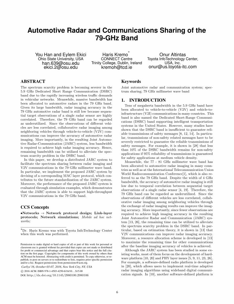
2.1 System DesignAs shown in Figure 1, the proposed JARC systems is com-
prised of the left-side control plane and the right-side dataplane. Apart from the Physical Layer block on the bottomand the Network Layer block on the top, the data plane con-sists of three core components in the MAC layer: periodicneighbor discovery, periodic link establishment/maintenanceand data delivery. Details of the all the functionality blocksin Figure 1 are as follows.
Control PlaneThe core functionality block in the control plane is a JARCcontroller, which manages the operations of the JARC sys-
1IEEE 1609.4 denotes the IEEE Standard for Wireless Ac-cess in Vehicular Environments (WAVE) (Multi-channel Op-eration) in the DSRC band2IEEE 802.11ad defines PHY and MAC layer protocols forWLAN operating in the 60 GHz millimeter wave band
tem by considering multiple factors such as distributed re-quirement, directional antennas, synchronization accuracy,identification of neighboring vehicles, high mobility of vehi-cles, QoS requirements of various wireless applications, anduse of two bands for operation 3 operation requirements. Itis the core of the JARC system. As an example, the JARCcontroller determines the multiplexing strategies in the dataplane, i.e., Channel Access Scheduling blocks in Figure 1 .
Physical LayerWe consider two options for the PHY layer waveform de-sign. The first option is to use the OFDM waveform forboth radar imaging and vehicular communications [5, 9, 10,11, 23], and the second option is to use OFDM waveformonly for vehicular communications and use the conventionalFrequency Modulated Continuous Wave (FMCW) for radarimaging. In addition to the waveform design, other PHYlayer issues include antenna design, synchronization, beam-forming etc. Similar to the fact that IEEE 802.11p is anamendment to the IEEE 802.11 standards for WLANs inthe 2.4 GHz ISM band, the design of our PHY layer canalso refer to the IEEE 802.11ad standard for WLANs in the60 GHz millimeter wave band.
Network LayerThe network layer requires an on-demand routing engine,which is able to cope with distributed and directional fea-tures of the JARC system. It first makes a routing tableusing the input from the link establishment/maintenanceblock. Then, it receives routing requests from the data de-livery block and sends the routing table back to the datadelivery block. Since building the whole routing table forall the other vehicles at every vehicle can incur a significantamount of overhead and latency, an on-demand routing pro-tocol is preferred.
Periodic Neighbor DiscoveryThe neighbor discovery block first receives channel accessscheduling decisions from the control plane, which deals withmultiplexing of the radar frequency band among neighbor-ing vehicles to avoid mutual interference. Then, neighborscanning is performed in both the DSRC band and the radarband. Specifically, the automotive radars detect neighboringvehicles through radar imaging using the 79 GHz band, andthe control radio detects neighboring vehicles through over-hearing their broadcast information in the 5.9 GHz band.The control radio itself also broadcasts its own identity in-formation such that it can be detected by the control radiosof neighboring vehicles. For the neighbor discovery in theradar band, a vehicle can only obtain location and mobil-ity information of its neighbors while the neighbor discoveryin the DSRC band enables the vehicle to obtain identityinformation of the neighbors 4. Therefore, the vehicle canidentify its neighbors by combining the detected neighborinformation in the two bands. Finally, the neighbor infor-mation is sent to the link establishment/maintenance block.
3Here, “two bands” denote the 5.9 GHz DSRC band (controlchannel) and the 79 GHz band (vehicular communicationchannels)4This minimal information collection enables the use of thissystem world-wide, including in Japan, where DSRC channelcarries only standard heartbeat messages with no additionalinformation.
7
Figure 1: The proposed JARC system
Periodic Link Establishment/MaintenanceAs shown in Figure 1, the operations for link establishmentand maintenance depend on the operating frequency band.More specifically, in the DSRC band, a vehicle can broadcastits link establishment and maintenance information whilein the radar band only directional unicast communicationis supported. Moreover, multiplexing schemes are requiredfor both bands to avoid mutual interference, which is de-termined by the JARC controller. In order to establish alink with one of its neighbors, the vehicle needs to start ahandshake with the neighbor. To verify that the previouslyestablished channel is still alive (i.e., maintain the connec-tion), the vehicle can use a simple heartbeat scheme. If not,a link outage handler is needed to deal with the link outageevent. Finally, the vehicle makes its local one-hop routingtable and sends it to the Network Layer block.
Data DeliveryAs shown in Figure 1, the Data Delivery block performsroute discovery, channel access scheduling, and data for-warding sequentially when transmission requests are receivedfrom the Network Layer. The routing table is acquired fromthe Network Layer and the multiplexing scheme is deter-mined by the JARC controller. Moreover, if a transmissionis not acknowledged by the receiver, a transmission failurehandler is used to deal with the lost frames, e.g., retrans-mit the frames before timeout or discard the frames aftertimeout.
2.2 System AnalysisThe development of the JARC system is faced with two
main challenges: the controller design as well as the routingengine design. As shown in Figure 1, the controller design is
faced with many requirements such as distributed and direc-tional operation across two bands, as well as high mobilityof vehicles. In particular, the controller must support thethree JARC modules in the data plane, i.e., neighbor dis-covery, link establishment/maintenance and data delivery.Since the three modules can use different bands and havedifferent requirements, it is a great challenge to provide ef-ficient scheduling and coordination service for them.
Since current vehicular communications use the 5.9 GHzDSRC band, most existing vehicular routing protocols arefor omnidirectional antennas. However, some distributedand directional routing protocols designed for general mobilead hoc networks can provide insights into the design of ourrouting engine, e.g., [7, 17, 18].
2.3 MAC Protocol DesignBased on the system design in Figure 1, we continue to
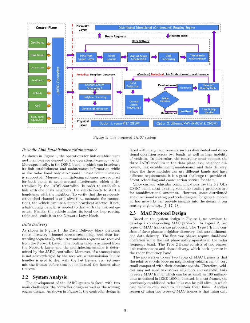
develop a corresponding MAC protocol. In Figure 2, twotypes of MAC frames are proposed. The Type 1 frame con-sists of three phases: neighbor discovery, link establishment,and data delivery. The first two phases require dual-bandoperation while the last phase solely operates in the radarfrequency band. The Type 2 frame consists of two phases:link maintenance and data delivery, which both operate inthe radar frequency band.
The motivation to use two types of MAC frames is thatthe relative speeds between neighboring vehicles can be verysmall compared with their absolute speeds. Therefore, vehi-cles may not need to discover neighbors and establish linksin every MAC frame, which can be as small as 100 millisec-onds as defined in IEEE 1609.4. Instead, in most frames, thepreviously established radar links can be still alive, in whichcase vehicles only need to maintain these links. Anotherreason of using two types of MAC frames is that using only
8
Figure 2: The proposed MAC protocol
Type 1 frames incurs a large amount of control overhead.Since both the Phase 1 and 2 intervals of the Type 1 frameare proportional to vehicle density, this can incur congestionon the JARC control channel. Hence, a large portion of theType 1 frame needs to be allocated to the two control in-tervals under high vehicle density. In contrast, the controlinterval in the Type 2 frame is rather short because the linkmaintenance is only conducted in the radar frequency band.Therefore, the Type 1 frame is used if and only if a freeradar interface needs to establish a link with its neighborswhile Type 2 frame is used when the previously establishedlink is still alive.
Details of the MAC protocol are as follows.
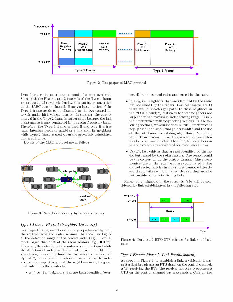
Figure 3: Neighbor discovery by radio and radars
Type 1 Frame: Phase 1 (Neighbor Discovery)In a Type 1 frame, neighbor discovery is performed by boththe control radio and radar sensors. As shown in Figure3, the detection range of the control radio (e.g., 1 km) ismuch larger than that of the radar sensors (e.g., 100 m).Moreover, the detection of the radio is omnidirectional whilethe detection of radars is directional. Therefore, differentsets of neighbors can be found by the radio and radars. LetS1 and S2 be the sets of neighbors discovered by the radioand radars, respectively, and the neighbors in S1 ∪ S2 canbe divided into three subsets:
• S1 ∩ S2, i.e., neighbors that are both identified (over-
heard) by the control radio and sensed by the radars.
• S1 \ S2, i.e., neighbors that are identified by the radiobut not sensed by the radars. Possible reasons are 1)there are no line-of-sight paths to these neighbors inthe 79 GHz band; 2) distances to these neighbors arelarger than the maximum radar sensing range; 3) mu-tual interference with neighboring vehicles. In the fol-lowing sections, we assume that mutual interference isnegligible due to small enough beamwidth and the useof efficient channel scheduling algorithms. Moreover,the first two reasons make it impossible to establish alink between two vehicles. Therefore, the neighbors inthis subset are not considered for establishing links.
• S2 \ S1, i.e., vehicles that are not identified by the ra-dio but sensed by the radar sensors. One reason couldbe the congestion on the control channel. Since com-munications on the radar band are coordinated by thecontrol radio, vehicles in this subset cannot efficientlycoordinate with neighboring vehicles and thus are alsonot considered for establishing links.
Hence, only neighbors in the subset S1 ∩ S2 will be con-sidered for link establishment in the following step.
Figure 4: Dual-band RTS/CTS scheme for link establish-ment
Type 1 Frame: Phase 2 (Link Establishment)As shown in Figure 4, to establish a link, a vehicular trans-mitter first broadcasts an RTS signal on the control channel.After receiving the RTS, the receiver not only broadcasts aCTS on the control channel but also sends a CTS on the
9
radar band. The CTS on the control channel is to: 1) verifythe RTS signal has been received; 2) broadcast informationon the radar link being established; 3) broadcast resourcereservation for the link being established in the upcomingdata delivery phase, which will be discussed in the next para-graph. The CTS on the radar band is to: 1) verify the RTSsignal has been received; 2) verify that the radar link beingestablished is valid. Note that since one of the DSRC servicechannels is used as the JARC control channel, RTS/CTS ex-change on the JARC control channel would be the exchangeof data on the actual service channel. For the multiplexingscheme in this phase, in addition to listen-before-talk, moresophisticated schemes can be used (e.g., [22][27]).
Figure 5: A TDMA-based multiplexing scheme
As shown in Figure 5, Phase 3 is divided into multipletime bursts, where a burst is defined as a resource unit inthe time domain. To transmit in Phase 3, the vehiculartransmitter must first reserve at least a burst through theCSMA/CA contention scheme in the DSRC band. Morespecifically, the burst reservation information is included inthe omnidirectional RTS/CTS messages that are broadcaston the control channel. After overhearing these messages, allvehicles mark the bursts as reserved. When a vehicle wantsto establish a link, it must find at least a burst that hasnot been reserved. Then, based on its need, it can reservea couple of bursts starting from the first available burst.Alternatively, since all the burst reservation decisions aremade by individual vehicles, every vehicle can be forced toreserve at most one burst in order to ensure fairness.
Since beamwidth of the communications links in the 79GHz is usually quite small, concurrent communications canbe adopted to leverage spatial reuse of the 79 GHz millime-ter wave band. However, the mutual interference issue alsobecomes more complicated due to the non-zero beamwidthas well as the reflection of communication signals by neigh-boring vehicles and roadside obstacles. Since the mutual in-terference issue in millimeter wave ad hoc networks is still animportant open research issue [21], as the very first step, weadopt the traditional TDMA-based multiple access schemeillustrated in Figure 5.
Type 1 Frame: Phase 3 (Data Delivery)After a link is established, a vehicle starts transmitting data.If a neighbor cannot be reached in one hop, a routing proto-col is required. For example, the directional AODV protocolcan be used to find routes in on-demand manner [16]. Fi-nally, if the data transmission is not acknowledged by thereceiver within a certain time, the transmitter can: 1) re-transmit the data on the control channel if they are urgent;2) retransmit the data in the next frame if they are not
urgent; 3) discard them if a timeout occurs.
Type 2 FrameAs shown in Figure 2, in Phase 1 of a Type 2 frame, aheartbeat scheme (similar to RTS/CTS) is used to maintainpreviously established radar links. Specifically, the trans-mitter simply sends a HELLO message to the receiver andthe receiver sends a ACK message if it receives the HELLOmessage. If the link is still alive, it will continue to be usedfor data delivery. Otherwise, the link will not be used andthe vehicle will try to establish a new link in the next frameusing the Type 1 frame. Moreover, the data delivery phaseis identical with the data delivery phase of the Type 1 frame.
3. SYSTEM EVALUATIONIn this section, we first present details on the simulation
tools used in our evaluations. Then, we explain the sim-ulation setup such as the road topology model, the radarlink model, as well as the simulation parameters. There-after, we evaluate the performance of the proposed JARCsystem through simulations. In particular, we will study twoproblems:
1. impact of radar link availability on the system perfor-mance;
2. impact of Type 1 frame control intervals on the systemperformance.
3.1 Simulation PlatformTwo simulation tools are used in our evaluations: Net-
work Simulator 3 (ns3) [2] and Simulation of Urban Mo-bility (SUMO) [3]. ns3 is a popular network simulator inboth industry and academia because it provides models ofhow packet data networks work and perform, and providesa simulation engine for users to conduct simulation exper-iments. We implemented the proposed JARC system bydeveloping a C++ JARC module in ns3.
SUMO is an open source, highly portable, microscopicand continuous road traffic simulation package designed tohandle large road networks. SUMO allows modeling of traf-fic systems including road vehicles, public transport, andpedestrians. SUMO includes many supporting tools thathandle tasks such as route finding, visualization, networkimport and emission calculation. All the road topology mod-els used in our simulations are generated using SUMO andthen ported to ns3.
3.2 Road Traffic Model
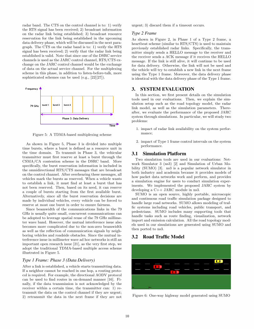
Figure 6: One-way highway model generated using SUMO
10
As an example shown in Figure 6, a one-way highwaymodel is generated using SUMO. The highway is 40,000 me-ters long and 12 meters wide. It has three straight lanes,each of which is 4 meters wide. All vehicles must move fromthe west end of the highway to the east end, and the aver-age distance between a vehicle and its front (and/or rear)vehicle is 15 meters. The number of vehicles in the networkis changed multiple times to study the performance of theJARC system under different vehicle densities. Specifically,the number of vehicles is taken from 6, 12, 18 · · · 96, 100. Notethat we also studied other road traffic models like intersec-tions with traffic lights, which are not shown in this paperdue to space constraint.
3.3 Radar Link ModelIn our simulations, a radar communication link is modeled
as a bi-directional point-to-point link. Main properties of thelink are as follows. Firstly, a link between two vehicles canbe established if and only if: 1) the distance between the twovehicles is less than the radar communication range, whichis set to 150 meters in our simulations; 2) at least one line-of-sight path exists between the two vehicles. Secondly, avehicle can establish at most four radar links simultaneouslywith neighboring vehicles. The reason is that in practiceeach vehicle only has a limited number of onboard radars,e.g., four radar sensors in the front, rear, left and right sideof the vehicle. Finally, Since vehicular radar links usuallyhave shorter lifetimes than radio-based communication links,we model the availability of a radar link as a continuoustime Markov ON-OFF process. Let E[ton], E[toff ] be theaverage ON and OFF time, respectively, and we define theLink Availability Probability (LAP) as:
LAP =E[ton]
E[ton] + E[toff ]. (1)
3.4 Simulation ParametersThe main system parameters of our simulations are as
follows.
• JARC MAC Frame. Similar to IEEE 1609.4 where aMAC frame is 100 milliseconds long, both Type 1 and2 frames are set to 200 milliseconds long. We run eachsimulation example for 10 minutes.
• Control Interval of Type 1 Frame (i.e., Phase 1 andPhase 2). Since the control interval can affect thenumber of established radar links, we consider threescenarios for (Phase 1, Phase 2) interval pairs: smallintervals (5 ms, 15 ms), medium intervals (10 ms, 30ms), and large intervals (20 ms, 60 ms). Therefore,Phase 3 is 180, 160 and 120 ms long, respectively.
• Control Interval of Type 2 Frame (i.e., Phase 1). Sincethe link maintenance is only performed on radar links,merely a short period of time is required, which is setto 2 milliseconds in our simulations.
• Link Availability Probability (LAP). Two scenariosare considered: small probability (LAP = 0.25) andlarge probability (LAP = 0.95).
• Wireless Applications. Whenever a radar link is estab-lished between two vehicles, UDP packets are trans-mitted from one vehicle to the other with Constant
Bit Rate (CBR) of 3 Gbps, e.g., using QPSK or 16-QAM modulation schemes [25].
• Routing Engine. Since only one-hop transmissions arerequired in our simulations, no routing protocol is used.Instead, vehicles only maintain their one-hop neigh-bors. Note that simulation of multi-hop networks isregarded as one of our future works.
• Performance Metrics. The performance of the pro-posed JARC system is evaluated through four metrics:1) the total number of established links in the network,2) the throughput of the whole network, 3) the aver-age number of established links at a vehicle, and 4) theaverage throughput at a vehicle.
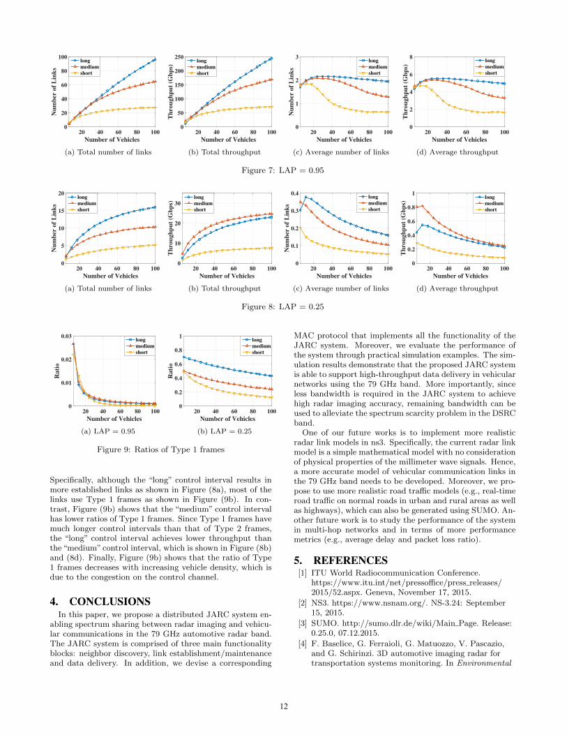
3.5 Simulation ResultsThe performance of the JARC system is shown in Figure 7
(LAP = 0.95) and Figure 8 (LAP = 0.25). In these figures,“small”, “medium” and “large” denote small, medium andlarge control intervals in Type 1 frames, respectively. Recallthat we consider three scenarios for (Phase 1, Phase 2) inter-val pairs: small intervals (5 ms, 15 ms), medium intervals (10ms, 30 ms), and large intervals (20 ms, 60 ms). ComparingFigure 7 and 8, we can find that larger LAP values lead tomore established links as well as higher throughput, whichis because the LAP value represents reliability of the radarlinks. In addition to the aforementioned four performancemetrics, the ratio of Type 1 frames over the total amount offrames is also shown in Figure 9. Since the control intervalof Type 1 frames is much longer than that of Type 2 frames,the radar link throughput of Type 1 frames is lower thanthat of Type 2 frames. Hence, the ratio of Type 1 framesaffects the throughput of the network.
Figure 7 shows that longer control intervals in Type 1frames lead to more established radar links as well as higherthroughput. The reason for more established radar links isthat more time is allocated to neighbor discovery and linkestablishment. The reason for higher throughput is morecomplicated. The trade-off of choosing the Type 1 controlintervals is that longer control intervals can help establishmore radar links, but also lead to shorter data delivery time(i.e., lower throughput). In contrast, the control intervalof Type 2 frames is fixed, which is 2 milliseconds in oursimulations. Therefore, the network throughput is not onlydependent on the number of established links, but also af-fected by the ratio of Type 1 frames. However, Figure (9a)shows that only a small ratio of links use Type 1 frames dueto the reliability of radar links (i.e., LAP = 0.95). There-fore, the throughput of the network is almost proportionalto the number of established links. It can also be seen inFigure (9a) that the ratio of Type 1 frames decreases withincreasing vehicle density. This is because the radar linksare so stable that most of them can be successfully main-tained, and thus vehicles do not need to establish new linksusing Type 1 frames.
Figure (8a) and (8c) show that longer control intervalsin Type 1 frames lead to more established radar links andhigher throughput, respectively. The reason is that moretime is allocated to neighbor discovery and link establish-ment. Figure (8b) and (8d) show that longer control in-tervals in Type 1 frames not necessarily lead to higher net-work throughput due to the trade-off of choosing the Type 1frame control intervals explained in the previous paragraph.
11
20 40 60 80 100
Number of Vehicles
0
20
40
60
80
100N
um
ber
of
Lin
ks
long
medium
short
(a) Total number of links
20 40 60 80 100
Number of Vehicles
0
50
100
150
200
250
Th
rou
gh
pu
t (G
bp
s)
long
medium
short
(b) Total throughput
20 40 60 80 100
Number of Vehicles
0
1
2
3
Nu
mb
er o
f L
ink
s
long
medium
short
(c) Average number of links
20 40 60 80 100
Number of Vehicles
0
2
4
6
8
Th
rou
gh
pu
t (G
bp
s)
long
medium
short
(d) Average throughput
Figure 7: LAP = 0.95
20 40 60 80 100
Number of Vehicles
0
5
10
15
20
Nu
mb
er o
f L
ink
s
long
medium
short
(a) Total number of links
20 40 60 80 100
Number of Vehicles
0
10
20
30
Th
rou
gh
pu
t (G
bp
s)
long
medium
short
(b) Total throughput
20 40 60 80 100
Number of Vehicles
0
0.1
0.2
0.3
0.4
Nu
mb
er o
f L
ink
s
long
medium
short
(c) Average number of links
20 40 60 80 100
Number of Vehicles
0
0.2
0.4
0.6
0.8
1
Th
rou
gh
pu
t (G
bp
s)
long
medium
short
(d) Average throughput
Figure 8: LAP = 0.25
20 40 60 80 100
Number of Vehicles
0
0.01
0.02
0.03
Ra
tio
long
medium
short
(a) LAP = 0.95
20 40 60 80 100
Number of Vehicles
0
0.2
0.4
0.6
0.8
1
Ra
tio
long
medium
short
(b) LAP = 0.25
Figure 9: Ratios of Type 1 frames
Specifically, although the “long” control interval results inmore established links as shown in Figure (8a), most of thelinks use Type 1 frames as shown in Figure (9b). In con-trast, Figure (9b) shows that the “medium” control intervalhas lower ratios of Type 1 frames. Since Type 1 frames havemuch longer control intervals than that of Type 2 frames,the “long” control interval achieves lower throughput thanthe“medium”control interval, which is shown in Figure (8b)and (8d). Finally, Figure (9b) shows that the ratio of Type1 frames decreases with increasing vehicle density, which isdue to the congestion on the control channel.
4. CONCLUSIONSIn this paper, we propose a distributed JARC system en-
abling spectrum sharing between radar imaging and vehicu-lar communications in the 79 GHz automotive radar band.The JARC system is comprised of three main functionalityblocks: neighbor discovery, link establishment/maintenanceand data delivery. In addition, we devise a corresponding
MAC protocol that implements all the functionality of theJARC system. Moreover, we evaluate the performance ofthe system through practical simulation examples. The sim-ulation results demonstrate that the proposed JARC systemis able to support high-throughput data delivery in vehicularnetworks using the 79 GHz band. More importantly, sinceless bandwidth is required in the JARC system to achievehigh radar imaging accuracy, remaining bandwidth can beused to alleviate the spectrum scarcity problem in the DSRCband.
One of our future works is to implement more realisticradar link models in ns3. Specifically, the current radar linkmodel is a simple mathematical model with no considerationof physical properties of the millimeter wave signals. Hence,a more accurate model of vehicular communication links inthe 79 GHz band needs to be developed. Moreover, we pro-pose to use more realistic road traffic models (e.g., real-timeroad traffic on normal roads in urban and rural areas as wellas highways), which can also be generated using SUMO. An-other future work is to study the performance of the systemin multi-hop networks and in terms of more performancemetrics (e.g., average delay and packet loss ratio).
5. REFERENCES[1] ITU World Radiocommunication Conference.
https://www.itu.int/net/pressoffice/press releases/2015/52.aspx. Geneva, November 17, 2015.
[4] F. Baselice, G. Ferraioli, G. Matuozzo, V. Pascazio,and G. Schirinzi. 3D automotive imaging radar fortransportation systems monitoring. In Environmental
12
Energy and Structural Monitoring Systems (EESMS),2014 IEEE Workshop on, pages 1–5, Sept 2014.
[5] M. Braun, C. Sturm, A. Niethammer, and F. K.Jondral. Parametrization of joint OFDM-based radarand communication systems for vehicular applications.In Personal, Indoor and Mobile RadioCommunications, 2009 IEEE 20th InternationalSymposium on, pages 3020–3024, Sept 2009.
[6] Q. Chen, D. Jiang, and L. Delgrossi. IEEE 1609.4DSRC multi-channel operations and its implicationson vehicle safety communications. In 2009 IEEEVehicular Networking Conference (VNC), pages 1–8,Oct 2009.
[7] L. Ding, W. Wu, J. Willson, H. Du, and W. Lee.Efficient virtual backbone construction with routingcost constraint in wireless networks using directionalantennas. Mobile Computing, IEEE Transactions on,11(7):1102–1112, July 2012.
[8] K. Fawaz, A. Ghandour, M. Olleik, and H. Artail.Improving reliability of safety applications in vehiclead hoc networks through the implementation of acognitive network. In Telecommunications (ICT), 2010IEEE 17th International Conference on, pages798–805, April 2010.
[9] D. Garmatyuk and J. Schuerger. Conceptual design ofa dual-use radar/communication system based onOFDM. In Military Communications Conference,2008. MILCOM 2008. IEEE, pages 1–7, Nov 2008.
[10] D. Garmatyuk, J. Schuerger, and K. Kauffman.Multifunctional software-defined radar sensor anddata communication system. IEEE Sensors Journal,11(1):99–106, Jan 2011.
[11] D. Garmatyuk, J. Schuerger, Y. T. Morton, K. Binns,M. Durbin, and J. Kimani. Feasibility study of amulti-carrier dual-use imaging radar andcommunication system. In Radar Conference, 2007.EuRAD 2007. European, pages 194–197, Oct 2007.
[12] A. J. Ghandour, K. Fawaz, H. Artail, M. Di Felice,and L. Bononi. Improving vehicular safety messagedelivery through the implementation of a cognitivevehicular network. Ad Hoc Netw., 11(8):2408–2422,Nov. 2013.
[13] Y. Han, E. Ekici, H. Kremo, and O. Altintas. Optimalspectrum utilization in joint automotive radar andcommunication networks. In Modeling andOptimization in Mobile, Ad Hoc, and WirelessNetworks (WiOpt), 2016 14th InternationalSymposium on, May 2016.
[14] G. Karagiannis, O. Altintas, E. Ekici, G. Heijenk,B. Jarupan, K. Lin, and T. Weil. Vehicularnetworking: A survey and tutorial on requirements,architectures, challenges, standards and solutions.Communications Surveys Tutorials, IEEE,13(4):584–616, Fourth 2011.
[15] P. Kumari, N. Gonzalez-Prelcic, and R. W. Heath.Investigating the IEEE 802.11ad standard formillimeter wave automotive radar. In VehicularTechnology Conference (VTC Fall), 2015 IEEE 82nd,pages 1–5, Sept 2015.
[16] A. N. Le, D.-W. Kum, S.-H. Lee, Y.-Z. Cho, and I.-S.Lee. Directional AODV routing protocol for wirelessmesh networks. In Personal, Indoor and Mobile Radio
[17] A. Nasipuri, J. Mandava, H. Manchala, andR. Hiromoto. On-demand routing using directionalantennas in mobile ad hoc networks. In ComputerCommunications and Networks, 2000. Proceedings.Ninth International Conference on, pages 535–541,2000.
[18] C. Papathanasiou, N. Dimitriou, T. Samios, andL. Tassiulas. On the use of distributed directiveantenna arrays in mobile OFDMA networks. InVehicular Technology Conference (VTC Spring), 2011IEEE 73rd, pages 1–5, May 2011.
[19] M. Rockl, T. Strang, and M. Kranz. V2Vcommunications in automotive multi-sensormulti-target tracking. In Vehicular TechnologyConference, 2008. VTC 2008-Fall. IEEE 68th, pages1–5, Sept 2008.
[20] C. W. Rossler, E. Ertin, and R. L. Moses. A softwaredefined radar system for joint communication andsensing. In Radar Conference (RADAR), 2011 IEEE,pages 1050–1055, May 2011.
[21] H. Shokri-Ghadikolaei and C. Fischione. Millimeterwave ad hoc networks: Noise-limited orinterference-limited? arXiv preprint arXiv:1509.04172,2015.
[22] S. Singh, R. Mudumbai, and U. Madhow. Distributedcoordination with deaf neighbors: Efficient mediumaccess for 60 GHz mesh networks. In INFOCOM, 2010Proceedings IEEE, pages 1–9, March 2010.
[23] Y. L. Sit and T. Zwick. MIMO OFDM radar withcommunication and interference cancellation features.In Radar Conference, 2014 IEEE, pages 0265–0268,May 2014.
[24] C. Sturm and W. Wiesbeck. Waveform design andsignal processing aspects for fusion of wirelesscommunications and radar sensing. Proceedings of theIEEE, 99(7):1236–1259, July 2011.
[25] X. Tie, K. Ramachandran, and R. Mahindra. Passiveand Active Measurement: 13th InternationalConference, PAM 2012, Vienna, Austria, March12-14th, 2012. Proceedings, chapter On 60 GHzWireless Link Performance in Indoor Environments,pages 147–157. Springer Berlin Heidelberg, Berlin,Heidelberg, 2012.
[26] M. Uchida, Y. Kagawa, and A. Okuno. Avehicle-to-vehicle communication and ranging systembased on spread spectrum technique-SScommunication radar. In Vehicle Navigation andInformation Systems Conference, 1994. Proceedings.,1994, pages 169–174, Aug 1994.
[27] J. Wang, Y. Fang, and D. Wu. SYN-DMAC: adirectional MAC protocol for ad hoc networks withsynchronization. In Military CommunicationsConference, 2005. MILCOM 2005. IEEE, pages2258–2263 Vol. 4, Oct 2005.
[28] Z. Wang and M. Hassan. How much of DSRC isavailable for non-safety use? In Proceedings of theFifth ACM International Workshop on VehiculArInter-NETworking, VANET ’08, pages 23–29, NewYork, NY, USA, 2008. ACM.