Approved for public release; further dissemination unlimited Preprint UCRL-JC-135060 Autonomous, Agile Micro- Satellites, and Supporting Technologies A. G. Ledebuhr, J. F. Kordas, L. C. Ng, M. S. Jones, J. C. Whitehead, E. Brietfeller, R. J. Gaughan, M. D. Dittman, B. Wilson This article was submitted to AIAA Space Technology Conference and Exposition Albuquerque, New Mexico September 28-30, 1999 July 19, 1999 Lawrence Livermore National Laboratory U.S. Department of Energy
Transcript
Approved for public release; further dissemination unlimited
PreprintUCRL-JC-135060
Autonomous, Agile Micro-Satellites, and SupportingTechnologies
A. G. Ledebuhr, J. F. Kordas, L. C. Ng, M. S. Jones, J. C.Whitehead, E. Brietfeller, R. J. Gaughan, M. D. Dittman, B.Wilson
This article was submitted toAIAA Space Technology Conference and ExpositionAlbuquerque, New MexicoSeptember 28-30, 1999
July 19, 1999LawrenceLivermoreNationalLaboratory
U.S. Department of Energy
DISCLAIMER This document was prepared as an account of work sponsored by an agency of the United StatesGovernment. Neither the United States Government nor the University of California nor any of theiremployees, makes any warranty, express or implied, or assumes any legal liability or responsibility forthe accuracy, completeness, or usefulness of any information, apparatus, product, or process disclosed, orrepresents that its use would not infringe privately owned rights. Reference herein to any specificcommercial product, process, or service by trade name, trademark, manufacturer, or otherwise, does notnecessarily constitute or imply its endorsement, recommendation, or favoring by the United StatesGovernment or the University of California. The views and opinions of authors expressed herein do notnecessarily state or reflect those of the United States Government or the University of California, andshall not be used for advertising or product endorsement purposes. This is a preprint of a paper intended for publication in a journal or proceedings. Since changes may bemade before publication, this preprint is made available with the understanding that it will not be citedor reproduced without the permission of the author.
This report has been reproduced directly from the best available copy.
Available to DOE and DOE contractors from the
Office of Scientific and Technical Information P.O. Box 62, Oak Ridge, TN 37831
Prices available from (423) 576-8401 http://apollo.osti.gov/bridge/
Available to the public from the
National Technical Information Service U.S. Department of Commerce
5285 Port Royal Rd., Springfield, VA 22161 http://www.ntis.gov/
OR
Lawrence Livermore National Laboratory
Technical Information Department’s Digital Library http://www.llnl.gov/tid/Library.html
Abstract. This paper updates the on-going effort at Lawrence Livermore National Laboratory to develop autonomous,agile micro-satellites (MicroSats). The objective of this development effort is to develop MicroSats weighing only a fewtens of kilograms, that are able to autonomously perform precision maneuvers and can be used telerobotically in a variety ofmission modes. The required capabilities include satellite rendezvous, inspection, proximity-operations, docking, andservicing. The MicroSat carries an integrated proximity-operations sensor-suite incorporating advanced avionics. A newself-pressurizing propulsion system utilizing a miniaturized pump and non-toxic mono-propellant hydrogen peroxide wassuccessfully tested. This system can provide a nominal 25 kg MicroSat with 200-300 m/s delta-v including a warm-gasattitude control system. The avionics is based on the latest PowerPC processor using a CompactPCI bus architecture, whichis modular, high-performance and processor-independent. This leverages commercial-off-the-shelf (COTS) technologiesand minimizes the effects of future changes in processors. The MicroSat software development environment uses the Vx-Works real-time operating system (RTOS) that provides a rapid development environment for integration of new softwaremodules, allowing early integration and test. We will summarize results of recent integrated ground flight testing of ourlatest non-toxic pumped propulsion MicroSat testbed vehicle operated on our unique dynamic air-rail.
IntroductionThis paper updates the on-going effort at LawrenceLivermore National Laboratory (LLNL) to developautonomous, agile micro-satellites (or MicroSats) capableof performing precision maneuvers in space.1 Itsummarizes the latest advances in the propulsion, sensor,and avionics areas. Results of recent integrated groundflight testing of our latest non-toxic pumped propulsionMicroSat testbed vehicle are reported. The objective of thisdevelopment effort is to develop MicroSats weighing only afew tens of kilograms, with 1 to 2 km/s of ∆v, capable ofperforming precision maneuvers autonomously ortelerobotically in space.
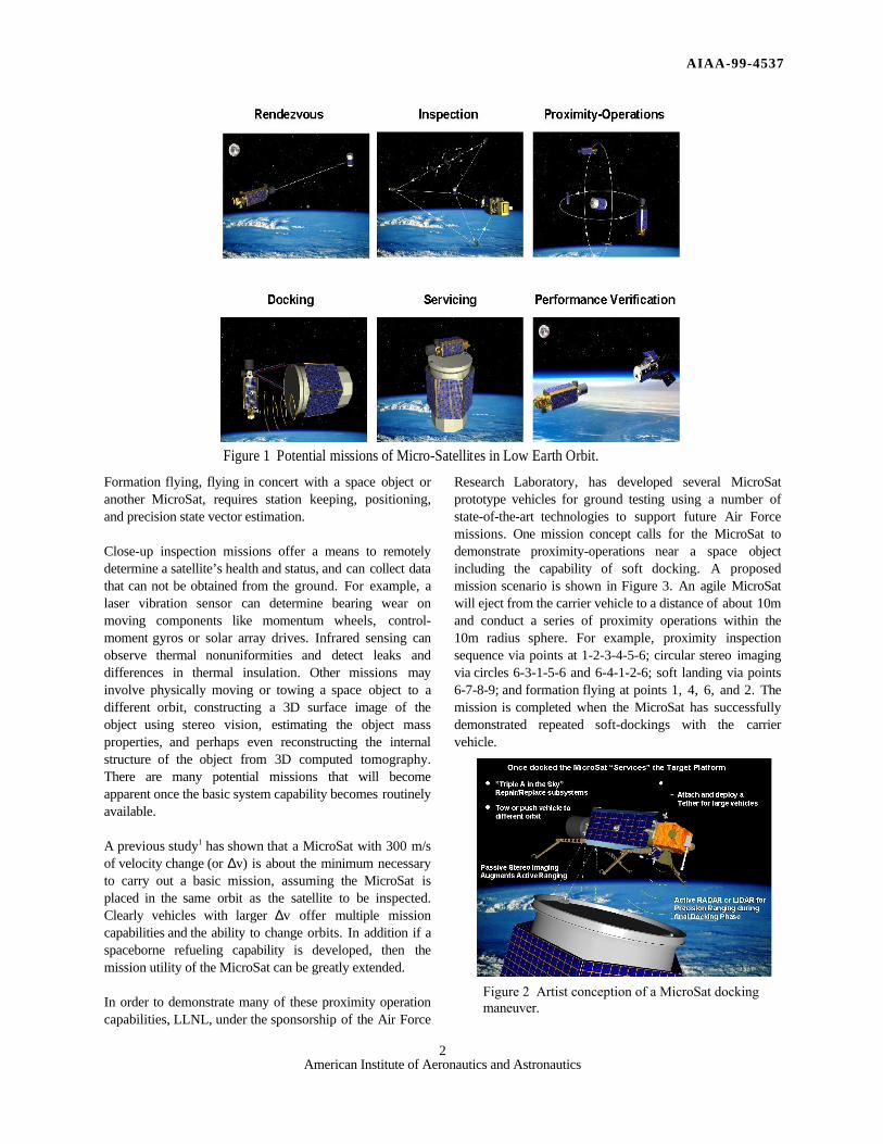
Potential MissionsPotential missions for MicroSats center on space “logistics”missions such as rescue and servicing, that will requirevehicles with the ability to perform a variety of functionsautonomously or semi-autonomously. These includerendezvous, inspection, proximity-operations (formationflying), docking, and robotic servicing functions(refueling, repowering or repairing). Figure 1 shows thevarious MicroSat missions of interest. Each of thesemission functions require key technical capabilities. Forexample, rendezvous with a space asset by performingorbit matching requires precision maneuvering. Inspection
of a space asset by flying to different view points of aninspection geometry requires precision MicroSatpositioning, pointing, tracking and imaging. A satelliterescue might involve docking, repairing or refueling thesatellite, followed by a departure, and post-rescueinspection. The rescue mission requires precision guidance,navigation, and control; precision ranging; high resolutionimaging; and some type of micro-robotic manipulation. Forexample, a variety of robotic arms could be used to enablethe MicroSat to perform a physical dock with a targetsatellite. Figure 2 illustrates one such approach. Here aMicroSat deploys four mechanical arms to grapple thelaunch vehicle interface flange as it lands on the targetsatellite. Once docked, a precision 6 degrees-of-freedommanipulator (actuator) could be used to align and plug anexternal connector into a targeted satellite’s umbilicalconnector for data collection, diagnostic measurements orre-powering. This servicing operation could be performedtelerobotically from the ground, to provide the flexibilityand problem solving of a human presence. Other spacelogistic operations such as the collection and de-orbiting ofhazardous space debris (junk) require precision vehicleguidance, navigation and control and a precision homingstrategy.
AIAA-99-4537
2American Institute of Aeronautics and Astronautics
Formation flying, flying in concert with a space object oranother MicroSat, requires station keeping, positioning,and precision state vector estimation.
Close-up inspection missions offer a means to remotelydetermine a satellite’s health and status, and can collect datathat can not be obtained from the ground. For example, alaser vibration sensor can determine bearing wear onmoving components like momentum wheels, control-moment gyros or solar array drives. Infrared sensing canobserve thermal nonuniformities and detect leaks anddifferences in thermal insulation. Other missions mayinvolve physically moving or towing a space object to adifferent orbit, constructing a 3D surface image of theobject using stereo vision, estimating the object massproperties, and perhaps even reconstructing the internalstructure of the object from 3D computed tomography.There are many potential missions that will becomeapparent once the basic system capability becomes routinelyavailable.
A previous study1 has shown that a MicroSat with 300 m/sof velocity change (or ∆v) is about the minimum necessaryto carry out a basic mission, assuming the MicroSat isplaced in the same orbit as the satellite to be inspected.Clearly vehicles with larger ∆v offer multiple missioncapabilities and the ability to change orbits. In addition if aspaceborne refueling capability is developed, then themission utility of the MicroSat can be greatly extended.
In order to demonstrate many of these proximity operationcapabilities, LLNL, under the sponsorship of the Air Force
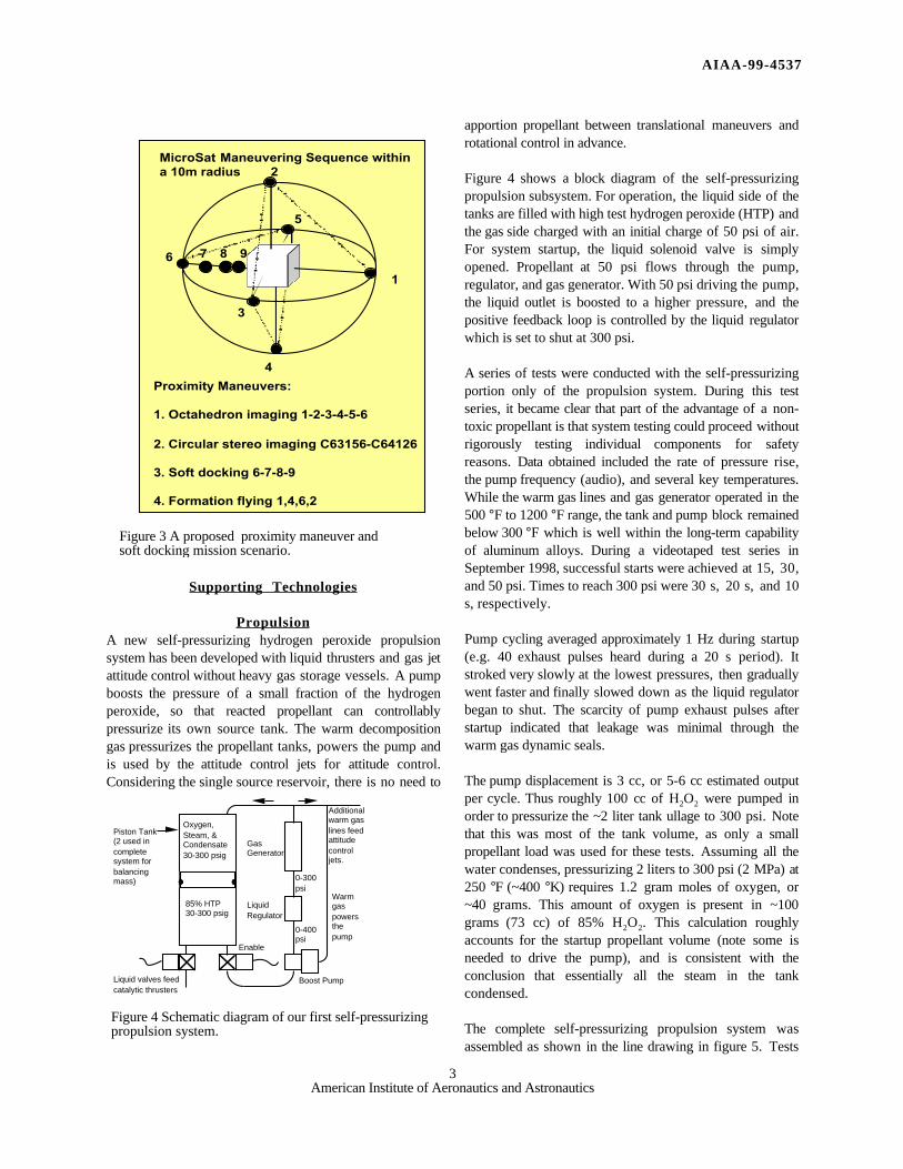
Research Laboratory, has developed several MicroSatprototype vehicles for ground testing using a number ofstate-of-the-art technologies to support future Air Forcemissions. One mission concept calls for the MicroSat todemonstrate proximity-operations near a space objectincluding the capability of soft docking. A proposedmission scenario is shown in Figure 3. An agile MicroSatwill eject from the carrier vehicle to a distance of about 10mand conduct a series of proximity operations within the10m radius sphere. For example, proximity inspectionsequence via points at 1-2-3-4-5-6; circular stereo imagingvia circles 6-3-1-5-6 and 6-4-1-2-6; soft landing via points6-7-8-9; and formation flying at points 1, 4, 6, and 2. Themission is completed when the MicroSat has successfullydemonstrated repeated soft-dockings with the carriervehicle.
Figure 1 Potential missions of Micro-Satellites in Low Earth Orbit.
Figure 2 Artist conception of a MicroSat dockingmaneuver.
AIAA-99-4537
3American Institute of Aeronautics and Astronautics
Supporting Technologies
PropulsionA new self-pressurizing hydrogen peroxide propulsionsystem has been developed with liquid thrusters and gas jetattitude control without heavy gas storage vessels. A pumpboosts the pressure of a small fraction of the hydrogenperoxide, so that reacted propellant can controllablypressurize its own source tank. The warm decompositiongas pressurizes the propellant tanks, powers the pump andis used by the attitude control jets for attitude control.Considering the single source reservoir, there is no need to
apportion propellant between translational maneuvers androtational control in advance.
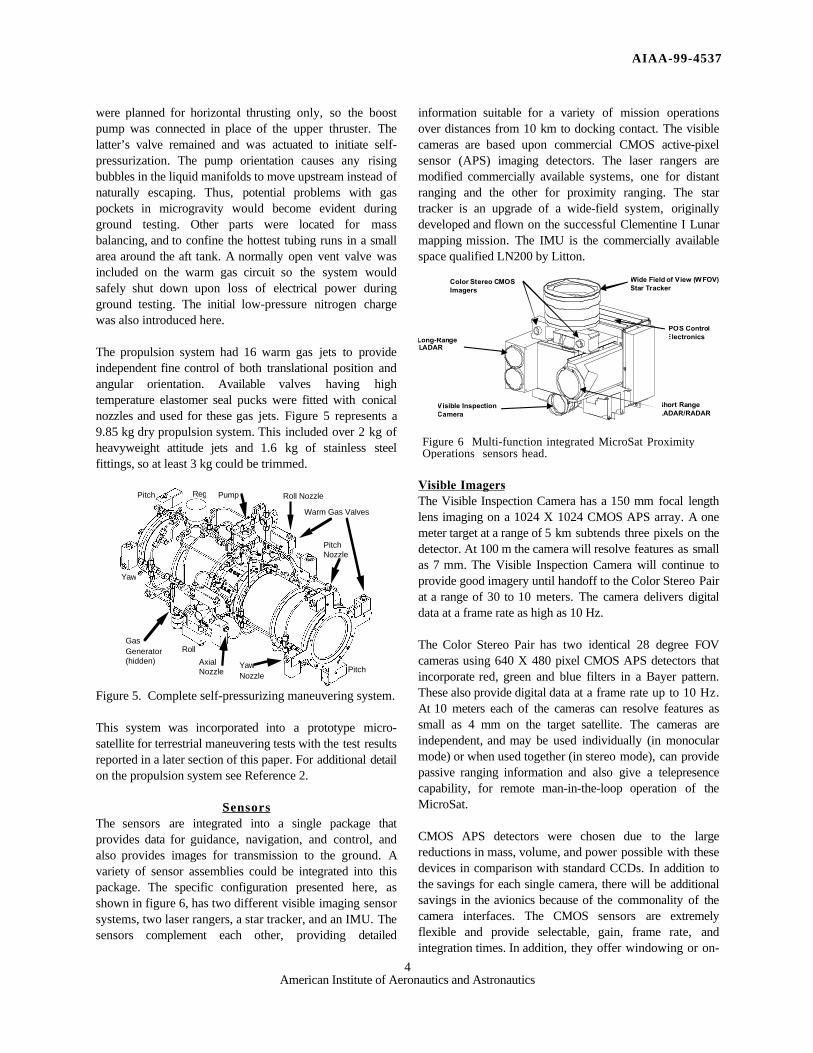
Figure 4 shows a block diagram of the self-pressurizingpropulsion subsystem. For operation, the liquid side of thetanks are filled with high test hydrogen peroxide (HTP) andthe gas side charged with an initial charge of 50 psi of air.For system startup, the liquid solenoid valve is simplyopened. Propellant at 50 psi flows through the pump,regulator, and gas generator. With 50 psi driving the pump,the liquid outlet is boosted to a higher pressure, and thepositive feedback loop is controlled by the liquid regulatorwhich is set to shut at 300 psi.
A series of tests were conducted with the self-pressurizingportion only of the propulsion system. During this testseries, it became clear that part of the advantage of a non-toxic propellant is that system testing could proceed withoutrigorously testing individual components for safetyreasons. Data obtained included the rate of pressure rise,the pump frequency (audio), and several key temperatures.While the warm gas lines and gas generator operated in the500 °F to 1200 °F range, the tank and pump block remainedbelow 300 °F which is well within the long-term capabilityof aluminum alloys. During a videotaped test series inSeptember 1998, successful starts were achieved at 15, 30,and 50 psi. Times to reach 300 psi were 30 s, 20 s, and 10s, respectively.
Pump cycling averaged approximately 1 Hz during startup(e.g. 40 exhaust pulses heard during a 20 s period). Itstroked very slowly at the lowest pressures, then graduallywent faster and finally slowed down as the liquid regulatorbegan to shut. The scarcity of pump exhaust pulses afterstartup indicated that leakage was minimal through thewarm gas dynamic seals.
The pump displacement is 3 cc, or 5-6 cc estimated outputper cycle. Thus roughly 100 cc of H2O2 were pumped inorder to pressurize the ~2 liter tank ullage to 300 psi. Notethat this was most of the tank volume, as only a smallpropellant load was used for these tests. Assuming all thewater condenses, pressurizing 2 liters to 300 psi (2 MPa) at250 °F (~400 °K) requires 1.2 gram moles of oxygen, or~40 grams. This amount of oxygen is present in ~100grams (73 cc) of 85% H2O2. This calculation roughlyaccounts for the startup propellant volume (note some isneeded to drive the pump), and is consistent with theconclusion that essentially all the steam in the tankcondensed.
The complete self-pressurizing propulsion system wasassembled as shown in the line drawing in figure 5. Tests
Enable
Boost Pump
85% HTP30-300 psig
Oxygen,Steam, &Condensate30-300 psig
GasGenerator
LiquidRegulator
0-400psi
Piston Tank(2 used incompletesystem forbalancingmass) 0-300
psi
Liquid valves feedcatalytic thrusters
Additionalwarm gaslines feedattitudecontroljets.
Warmgaspowersthepump
Figure 4 Schematic diagram of our first self-pressurizingpropulsion system.
Figure 3 A proposed proximity maneuver andsoft docking mission scenario.
1
2
3
4
5
6
MicroSat Maneuvering Sequence withina 10m radius
7 8 9
Proximity Maneuvers:
1. Octahedron imaging 1-2-3-4-5-6
2. Circular stereo imaging C63156-C64126
3. Soft docking 6-7-8-9
4. Formation flying 1,4,6,2
AIAA-99-4537
4American Institute of Aeronautics and Astronautics
were planned for horizontal thrusting only, so the boostpump was connected in place of the upper thruster. Thelatter’s valve remained and was actuated to initiate self-pressurization. The pump orientation causes any risingbubbles in the liquid manifolds to move upstream instead ofnaturally escaping. Thus, potential problems with gaspockets in microgravity would become evident duringground testing. Other parts were located for massbalancing, and to confine the hottest tubing runs in a smallarea around the aft tank. A normally open vent valve wasincluded on the warm gas circuit so the system wouldsafely shut down upon loss of electrical power duringground testing. The initial low-pressure nitrogen chargewas also introduced here.
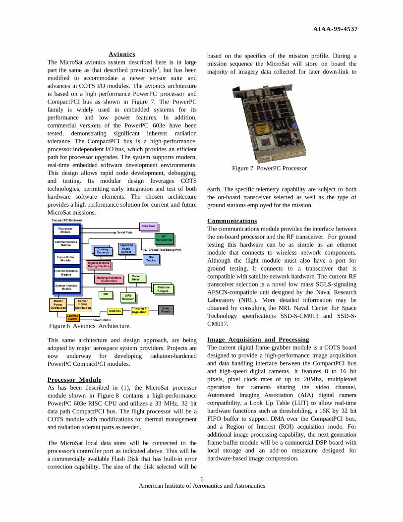
The propulsion system had 16 warm gas jets to provideindependent fine control of both translational position andangular orientation. Available valves having hightemperature elastomer seal pucks were fitted with conicalnozzles and used for these gas jets. Figure 5 represents a9.85 kg dry propulsion system. This included over 2 kg ofheavyweight attitude jets and 1.6 kg of stainless steelfittings, so at least 3 kg could be trimmed.
This system was incorporated into a prototype micro-satellite for terrestrial maneuvering tests with the test resultsreported in a later section of this paper. For additional detailon the propulsion system see Reference 2.
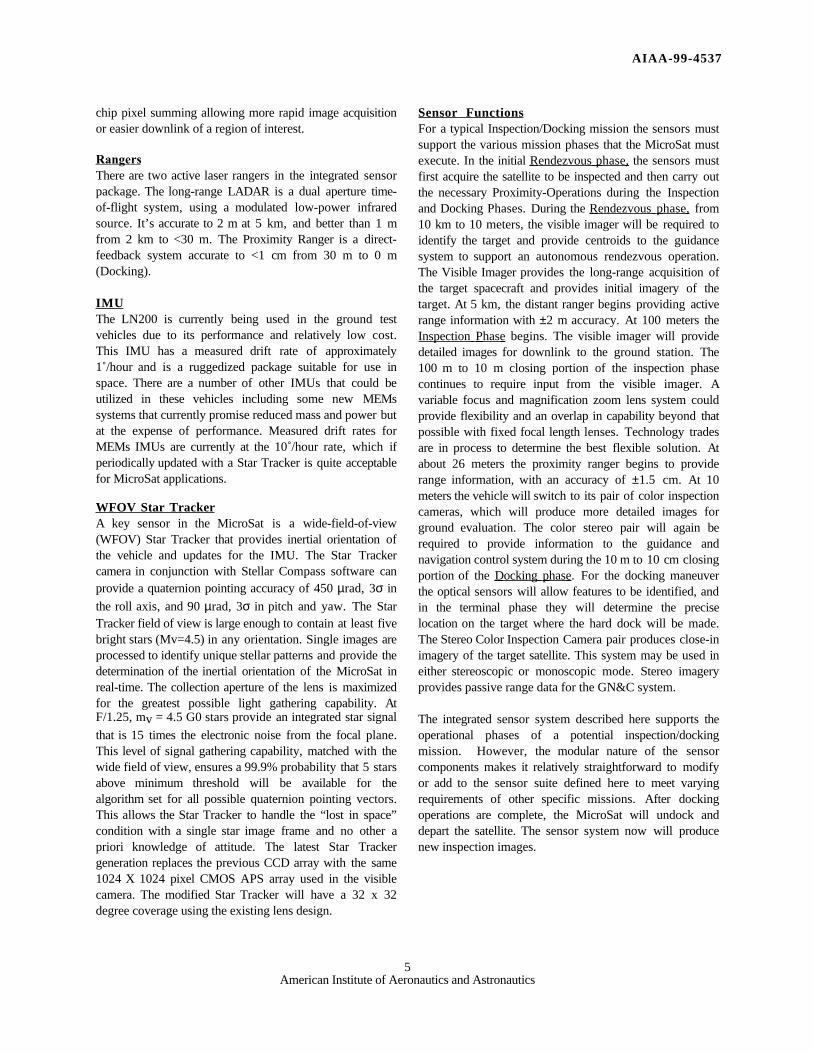
SensorsThe sensors are integrated into a single package thatprovides data for guidance, navigation, and control, andalso provides images for transmission to the ground. Avariety of sensor assemblies could be integrated into thispackage. The specific configuration presented here, asshown in figure 6, has two different visible imaging sensorsystems, two laser rangers, a star tracker, and an IMU. Thesensors complement each other, providing detailed
information suitable for a variety of mission operationsover distances from 10 km to docking contact. The visiblecameras are based upon commercial CMOS active-pixelsensor (APS) imaging detectors. The laser rangers aremodified commercially available systems, one for distantranging and the other for proximity ranging. The startracker is an upgrade of a wide-field system, originallydeveloped and flown on the successful Clementine I Lunarmapping mission. The IMU is the commercially availablespace qualified LN200 by Litton.
Visible ImagersThe Visible Inspection Camera has a 150 mm focal lengthlens imaging on a 1024 X 1024 CMOS APS array. A onemeter target at a range of 5 km subtends three pixels on thedetector. At 100 m the camera will resolve features as smallas 7 mm. The Visible Inspection Camera will continue toprovide good imagery until handoff to the Color Stereo Pairat a range of 30 to 10 meters. The camera delivers digitaldata at a frame rate as high as 10 Hz.
The Color Stereo Pair has two identical 28 degree FOVcameras using 640 X 480 pixel CMOS APS detectors thatincorporate red, green and blue filters in a Bayer pattern.These also provide digital data at a frame rate up to 10 Hz.At 10 meters each of the cameras can resolve features assmall as 4 mm on the target satellite. The cameras areindependent, and may be used individually (in monocularmode) or when used together (in stereo mode), can providepassive ranging information and also give a telepresencecapability, for remote man-in-the-loop operation of theMicroSat.
CMOS APS detectors were chosen due to the largereductions in mass, volume, and power possible with thesedevices in comparison with standard CCDs. In addition tothe savings for each single camera, there will be additionalsavings in the avionics because of the commonality of thecamera interfaces. The CMOS sensors are extremelyflexible and provide selectable, gain, frame rate, andintegration times. In addition, they offer windowing or on-
5American Institute of Aeronautics and Astronautics
chip pixel summing allowing more rapid image acquisitionor easier downlink of a region of interest.
RangersThere are two active laser rangers in the integrated sensorpackage. The long-range LADAR is a dual aperture time-of-flight system, using a modulated low-power infraredsource. It’s accurate to 2 m at 5 km, and better than 1 mfrom 2 km to <30 m. The Proximity Ranger is a direct-feedback system accurate to <1 cm from 30 m to 0 m(Docking).
IMUThe LN200 is currently being used in the ground testvehicles due to its performance and relatively low cost.This IMU has a measured drift rate of approximately1˚/hour and is a ruggedized package suitable for use inspace. There are a number of other IMUs that could beutilized in these vehicles including some new MEMssystems that currently promise reduced mass and power butat the expense of performance. Measured drift rates forMEMs IMUs are currently at the 10˚/hour rate, which ifperiodically updated with a Star Tracker is quite acceptablefor MicroSat applications.
WFOV Star TrackerA key sensor in the MicroSat is a wide-field-of-view(WFOV) Star Tracker that provides inertial orientation ofthe vehicle and updates for the IMU. The Star Trackercamera in conjunction with Stellar Compass software canprovide a quaternion pointing accuracy of 450 µrad, 3σ in
the roll axis, and 90 µrad, 3σ in pitch and yaw. The StarTracker field of view is large enough to contain at least fivebright stars (Mv=4.5) in any orientation. Single images areprocessed to identify unique stellar patterns and provide thedetermination of the inertial orientation of the MicroSat inreal-time. The collection aperture of the lens is maximizedfor the greatest possible light gathering capability. AtF/1.25, mv = 4.5 G0 stars provide an integrated star signal
that is 15 times the electronic noise from the focal plane.This level of signal gathering capability, matched with thewide field of view, ensures a 99.9% probability that 5 starsabove minimum threshold will be available for thealgorithm set for all possible quaternion pointing vectors.This allows the Star Tracker to handle the “lost in space”condition with a single star image frame and no other apriori knowledge of attitude. The latest Star Trackergeneration replaces the previous CCD array with the same1024 X 1024 pixel CMOS APS array used in the visiblecamera. The modified Star Tracker will have a 32 x 32degree coverage using the existing lens design.
Sensor FunctionsFor a typical Inspection/Docking mission the sensors mustsupport the various mission phases that the MicroSat mustexecute. In the initial Rendezvous phase, the sensors mustfirst acquire the satellite to be inspected and then carry outthe necessary Proximity-Operations during the Inspectionand Docking Phases. During the Rendezvous phase, from10 km to 10 meters, the visible imager will be required toidentify the target and provide centroids to the guidancesystem to support an autonomous rendezvous operation.The Visible Imager provides the long-range acquisition ofthe target spacecraft and provides initial imagery of thetarget. At 5 km, the distant ranger begins providing activerange information with ±2 m accuracy. At 100 meters theInspection Phase begins. The visible imager will providedetailed images for downlink to the ground station. The100 m to 10 m closing portion of the inspection phasecontinues to require input from the visible imager. Avariable focus and magnification zoom lens system couldprovide flexibility and an overlap in capability beyond thatpossible with fixed focal length lenses. Technology tradesare in process to determine the best flexible solution. Atabout 26 meters the proximity ranger begins to providerange information, with an accuracy of ±1.5 cm. At 10meters the vehicle will switch to its pair of color inspectioncameras, which will produce more detailed images forground evaluation. The color stereo pair will again berequired to provide information to the guidance andnavigation control system during the 10 m to 10 cm closingportion of the Docking phase . For the docking maneuverthe optical sensors will allow features to be identified, andin the terminal phase they will determine the preciselocation on the target where the hard dock will be made.The Stereo Color Inspection Camera pair produces close-inimagery of the target satellite. This system may be used ineither stereoscopic or monoscopic mode. Stereo imageryprovides passive range data for the GN&C system.
The integrated sensor system described here supports theoperational phases of a potential inspection/dockingmission. However, the modular nature of the sensorcomponents makes it relatively straightforward to modifyor add to the sensor suite defined here to meet varyingrequirements of other specific missions. After dockingoperations are complete, the MicroSat will undock anddepart the satellite. The sensor system now will producenew inspection images.
AIAA-99-4537
6American Institute of Aeronautics and Astronautics
AvionicsThe MicroSat avionics system described here is in largepart the same as that described previously1, but has beenmodified to accommodate a newer sensor suite andadvances in COTS I/O modules. The avionics architectureis based on a high performance PowerPC processor andCompactPCI bus as shown in Figure 7. The PowerPCfamily is widely used in embedded systems for itsperformance and low power features. In addition,commercial versions of the PowerPC 603e have beentested, demonstrating significant inherent radiationtolerance. The CompactPCI bus is a high-performance,processor independent I/O bus, which provides an efficientpath for processor upgrades. The system supports modern,real-time embedded software development environments.This design allows rapid code development, debugging,and testing. Its modular design leverages COTStechnologies, permitting early integration and test of bothhardware software elements. The chosen architectureprovides a high performance solution for current and futureMicroSat missions.
This same architecture and design approach, are beingadopted by major aerospace system providers. Projects arenow underway for developing radiation-hardenedPowerPC CompactPCI modules.
Processor ModuleAs has been described in (1), the MicroSat processormodule shown in Figure 8 contains a high-performancePowerPC 603e RISC CPU and utilizes a 33 MHz, 32 bitdata path CompactPCI bus. The flight processor will be aCOTS module with modifications for thermal managementand radiation tolerant parts as needed.
The MicroSat local data store will be connected to theprocessor's controller port as indicated above. This will bea commercially available Flash Disk that has built-in errorcorrection capability. The size of the disk selected will be
based on the specifics of the mission profile. During amission sequence the MicroSat will store on board themajority of imagery data collected for later down-link to
earth. The specific telemetry capability are subject to boththe on-board transceiver selected as well as the type ofground stations employed for the mission.
CommunicationsThe communications module provides the interface betweenthe on-board processor and the RF transceiver. For groundtesting this hardware can be as simple as an ethernetmodule that connects to wireless network components.Although the flight module must also have a port forground testing, it connects to a transceiver that iscompatible with satellite network hardware. The current RFtransceiver selection is a novel low mass SGLS-signalingAFSCN-compatible unit designed by the Naval ResearchLaboratory (NRL). More detailed information may beobtained by consulting the NRL Naval Center for SpaceTechnology specifications SSD-S-CM013 and SSD-S-CM017.
Image Acquisition and ProcessingThe current digital frame grabber module is a COTS boarddesigned to provide a high-performance image acquisitionand data handling interface between the CompactPCI busand high-speed digital cameras. It features 8 to 16 bitpixels, pixel clock rates of up to 20Mhz, multiplexedoperation for cameras sharing the video channel,Automated Imaging Association (AIA) digital cameracompatibility, a Look Up Table (LUT) to allow real-timehardware functions such as thresholding, a 16K by 32 bitFIFO buffer to support DMA over the CompactPCI bus,and a Region of Interest (ROI) acquisition mode. Foradditional image processing capability, the next-generationframe buffer module will be a commercial DSP board withlocal storage and an add-on mezzanine designed forhardware-based image compression.
CompactPCI Enclosure
Pro cessorModule
Frame BufferModule
MasterPower
Distribution
Data Store
Serial Ports
SensorPower
Distribution
StarTracker
MU
Signal/ElectricalMating Interface
RFTransponder
Batteries
LatchingSwitch Power Enable
CommunicationsModule
Ground Test/Debug Port
G PSReceiver
Charging &Regulation
SolarPanels
DockingCameras
(2)
System InterfaceModule
Docking Actuators/Controllers
External InterfaceModule
nspectionVisibleCamera
ValveDriver
MiniatureRangers
Figure 6 Avionics Architecture.
Figure 7 PowerPC Processor
AIAA-99-4537
7American Institute of Aeronautics and Astronautics
Vehicle ControlThe system interface module provides connection, control,and acquisition functions for the MicroSat guidance andnavigation elements. The current module is an IndustryPack (IP) carrier board that uses serial IP modules tocommunicate with the IMU, GPS, and Rangingcomponents. A digital I/O module controls the valvedrivers. Operations that require physical connectionsoutside the MicroSat are handled via the external interfacemodule. This includes control of mechanisms used indocking and servicing mission phases such as roboticarms, grappling fixtures, and electrical connectors.
Power Distribution SystemThe current MicroSat ground test vehicles have used lowcost rechargeable Ni-Cad cells. We plan to utilize Li-ionrechargeable batteries that are undergoing qualification forspace under Air Force sponsored efforts. There are severaladvanced solar cell technologies that can be used for futureflight vehicles. Dual-junction cells and concentrator arraysoffer the ability to maximize power generation in very lowmass and small areas. A specific choice will await futureflight design efforts.
Power ManagementThe power management scheme uses the approach asdescribed previously1. The power management controllermonitors and controls the power to all of the spacecraftloads. It communicates with the system processor toprovide the capability to make mode changes, carry outpower down commands to various components, andmonitor the power system condition. This link alsoprovides a way for the controller to signal the systemprocessor of power system alarms and to alert it to the needfor imminent shutdown. The MicroSat will enter a power-down mode autonomously by the system processor as aresult of preprogrammed mission operations or as a resultof detecting battery depletion via the master powerdistribution module. A second means is receipt andconfirmation of a power-down command from the groundstation.
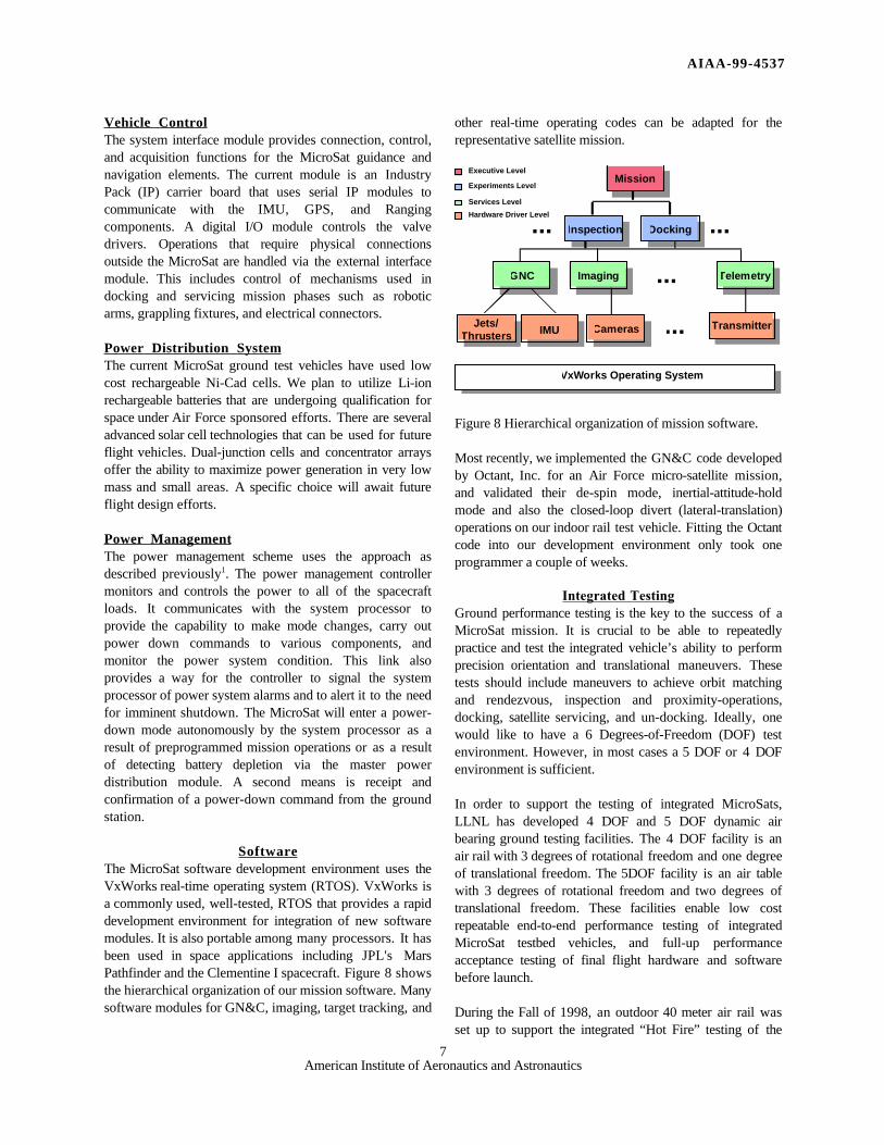
SoftwareThe MicroSat software development environment uses theVxWorks real-time operating system (RTOS). VxWorks isa commonly used, well-tested, RTOS that provides a rapiddevelopment environment for integration of new softwaremodules. It is also portable among many processors. It hasbeen used in space applications including JPL's MarsPathfinder and the Clementine I spacecraft. Figure 8 showsthe hierarchical organization of our mission software. Manysoftware modules for GN&C, imaging, target tracking, and
other real-time operating codes can be adapted for therepresentative satellite mission.
Executive Level
Experiments Level
Services Level
Hardware Driver Level
Jets/Thrusters
Mission
Inspection Docking
GNC Imaging Telemetry...
IMU Cameras Transmitter
VxWorks Operating System
...
... ...
Figure 8 Hierarchical organization of mission software.
Most recently, we implemented the GN&C code developedby Octant, Inc. for an Air Force micro-satellite mission,and validated their de-spin mode, inertial-attitude-holdmode and also the closed-loop divert (lateral-translation)operations on our indoor rail test vehicle. Fitting the Octantcode into our development environment only took oneprogrammer a couple of weeks.
Integrated TestingGround performance testing is the key to the success of aMicroSat mission. It is crucial to be able to repeatedlypractice and test the integrated vehicle’s ability to performprecision orientation and translational maneuvers. Thesetests should include maneuvers to achieve orbit matchingand rendezvous, inspection and proximity-operations,docking, satellite servicing, and un-docking. Ideally, onewould like to have a 6 Degrees-of-Freedom (DOF) testenvironment. However, in most cases a 5 DOF or 4 DOFenvironment is sufficient.
In order to support the testing of integrated MicroSats,LLNL has developed 4 DOF and 5 DOF dynamic airbearing ground testing facilities. The 4 DOF facility is anair rail with 3 degrees of rotational freedom and one degreeof translational freedom. The 5DOF facility is an air tablewith 3 degrees of rotational freedom and two degrees oftranslational freedom. These facilities enable low costrepeatable end-to-end performance testing of integratedMicroSat testbed vehicles, and full-up performanceacceptance testing of final flight hardware and softwarebefore launch.
During the Fall of 1998, an outdoor 40 meter air rail wasset up to support the integrated “Hot Fire” testing of the
AIAA-99-4537
8American Institute of Aeronautics and Astronautics
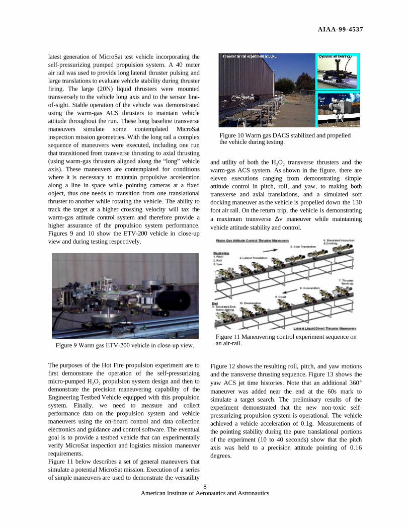
latest generation of MicroSat test vehicle incorporating theself-pressurizing pumped propulsion system. A 40 meterair rail was used to provide long lateral thruster pulsing andlarge translations to evaluate vehicle stability during thrusterfiring. The large (20N) liquid thrusters were mountedtransversely to the vehicle long axis and to the sensor line-of-sight. Stable operation of the vehicle was demonstratedusing the warm-gas ACS thrusters to maintain vehicleattitude throughout the run. These long baseline transversemaneuvers simulate some contemplated MicroSatinspection mission geometries. With the long rail a complexsequence of maneuvers were executed, including one runthat transitioned from transverse thrusting to axial thrusting(using warm-gas thrusters aligned along the “long” vehicleaxis). These maneuvers are contemplated for conditionswhere it is necessary to maintain propulsive accelerationalong a line in space while pointing cameras at a fixedobject, thus one needs to transition from one translationalthruster to another while rotating the vehicle. The ability totrack the target at a higher crossing velocity will tax thewarm-gas attitude control system and therefore provide ahigher assurance of the propulsion system performance.Figures 9 and 10 show the ETV-200 vehicle in close-upview and during testing respectively.
The purposes of the Hot Fire propulsion experiment are tofirst demonstrate the operation of the self-pressurizingmicro-pumped H2O2 propulsion system design and then todemonstrate the precision maneuvering capability of theEngineering Testbed Vehicle equipped with this propulsionsystem. Finally, we need to measure and collectperformance data on the propulsion system and vehiclemaneuvers using the on-board control and data collectionelectronics and guidance and control software. The eventualgoal is to provide a testbed vehicle that can experimentallyverify MicroSat inspection and logistics mission maneuverrequirements.Figure 11 below describes a set of general maneuvers thatsimulate a potential MicroSat mission. Execution of a seriesof simple maneuvers are used to demonstrate the versatility
and utility of both the H2O2 transverse thrusters and thewarm-gas ACS system. As shown in the figure, there areeleven executions ranging from demonstrating simpleattitude control in pitch, roll, and yaw, to making bothtransverse and axial translations, and a simulated softdocking maneuver as the vehicle is propelled down the 130foot air rail. On the return trip, the vehicle is demonstratinga maximum transverse ∆v maneuver while maintainingvehicle attitude stability and control.
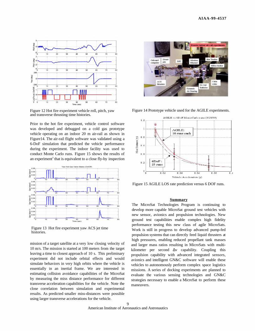
Figure 12 shows the resulting roll, pitch, and yaw motionsand the transverse thrusting sequence. Figure 13 shows theyaw ACS jet time histories. Note that an additional 360°maneuver was added near the end at the 60s mark tosimulate a target search. The preliminary results of theexperiment demonstrated that the new non-toxic self-pressurizing propulsion system is operational. The vehicleachieved a vehicle acceleration of 0.1g. Measurements ofthe pointing stability during the pure translational portionsof the experiment (10 to 40 seconds) show that the pitchaxis was held to a precision attitude pointing of 0.16degrees.
Figure 9 Warm gas ETV-200 vehicle in close-up view.Figure 11 Maneuvering control experiment sequence onan air-rail.
Figure 10 Warm gas DACS stabilized and propelledthe vehicle during testing.
AIAA-99-4537
9American Institute of Aeronautics and Astronautics
Figure 12 Hot fire experiment vehicle roll, pitch, yawand transverse thrusting time histories.
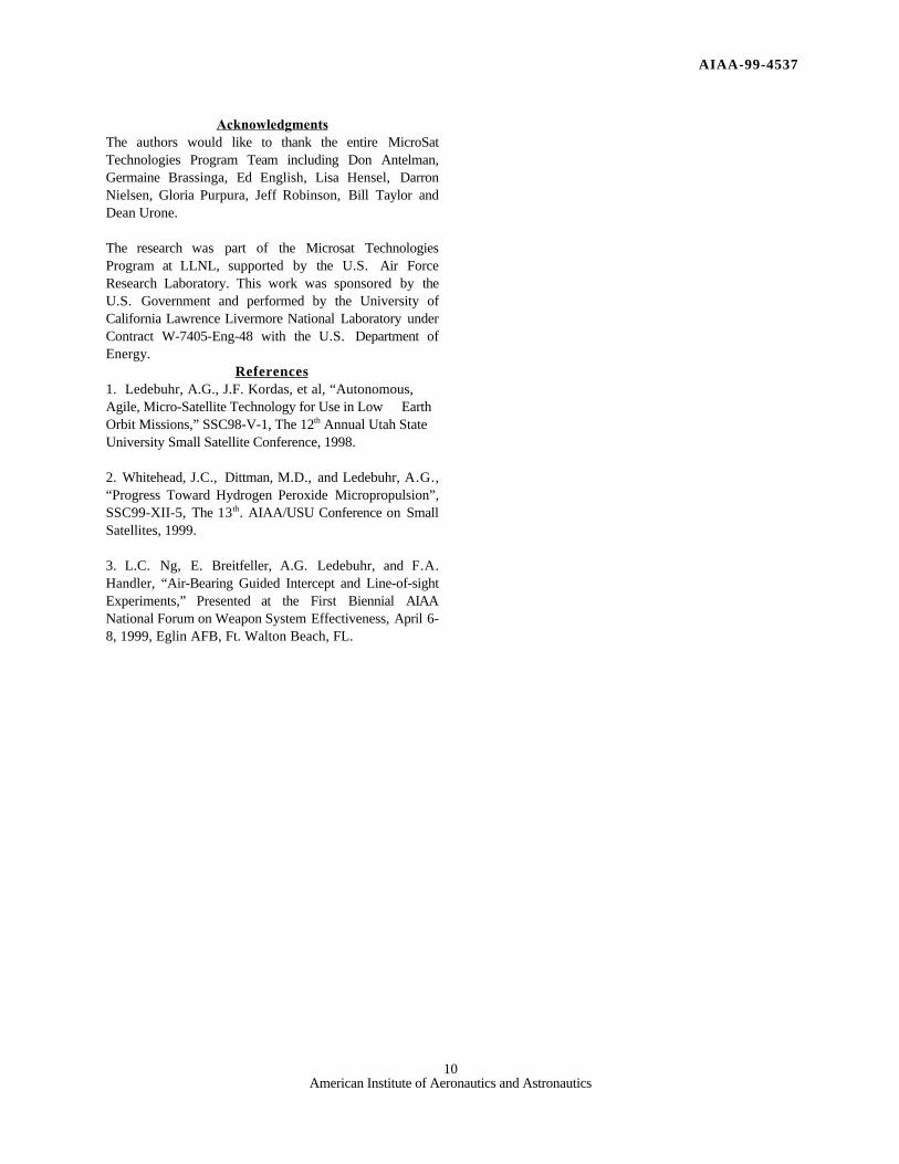
Prior to the hot fire experiment, vehicle control softwarewas developed and debugged on a cold gas prototypevehicle operating on an indoor 20 m air-rail as shown inFigure14. The air-rail flight software was validated using a6-DoF simulation that predicted the vehicle performanceduring the experiment. The indoor facility was used toconduct Monte Carlo runs. Figure 15 shows the results ofan experiment3 that is equivalent to a close fly-by inspection
mission of a target satellite at a very low closing velocity of10 m/s. The mission is started at 100 meters from the targetleaving a time to closest approach of 10 s. This preliminaryexperiment did not include orbital effects and wouldsimulate behaviors in very high orbits where the vehicle isessentially in an inertial frame. We are interested inestimating collision avoidance capabilities of the MicroSatby measuring the miss distance performance for differenttransverse acceleration capabilities for the vehicle. Note theclose correlation between simulation and experimentalresults. As predicted smaller miss-distances were possibleusing larger transverse accelerations for the vehicle.
SummaryThe MicroSat Technologies Program is continuing todevelop more capable MicroSat ground test vehicles withnew sensor, avionics and propulsion technologies. Newground test capabilities enable complex high fidelityperformance testing this new class of agile MicroSats.Work is still in progress to develop advanced pump-fedpropulsion systems that can directly feed liquid thrusters athigh pressures, enabling reduced propellant tank massesand larger mass ratios resulting in MicroSats with multi-kilometer per second ∆v capability. Coupling thispropulsion capability with advanced integrated sensors,avionics and intelligent GN&C software will enable thesevehicles to autonomously perform complex space logisticsmissions. A series of docking experiments are planned toevaluate the various sensing technologies and GN&Cstrategies necessary to enable a MicroSat to perform thesemaneuvers.
Figure 13 Hot fire experiment yaw ACS jet timehistories.
Figure 15 AGILE LOS rate prediction versus 6 DOF runs.
Figure 14 Prototype vehicle used for the AGILE experiments.
AIAA-99-4537
10American Institute of Aeronautics and Astronautics
AcknowledgmentsThe authors would like to thank the entire MicroSatTechnologies Program Team including Don Antelman,Germaine Brassinga, Ed English, Lisa Hensel, DarronNielsen, Gloria Purpura, Jeff Robinson, Bill Taylor andDean Urone.
The research was part of the Microsat TechnologiesProgram at LLNL, supported by the U.S. Air ForceResearch Laboratory. This work was sponsored by theU.S. Government and performed by the University ofCalifornia Lawrence Livermore National Laboratory underContract W-7405-Eng-48 with the U.S. Department ofEnergy.
References1. Ledebuhr, A.G., J.F. Kordas, et al, “Autonomous,Agile, Micro-Satellite Technology for Use in Low EarthOrbit Missions,” SSC98-V-1, The 12th Annual Utah StateUniversity Small Satellite Conference, 1998.
2. Whitehead, J.C., Dittman, M.D., and Ledebuhr, A.G.,“Progress Toward Hydrogen Peroxide Micropropulsion”,SSC99-XII-5, The 13th. AIAA/USU Conference on SmallSatellites, 1999.
3. L.C. Ng, E. Breitfeller, A.G. Ledebuhr, and F.A.Handler, “Air-Bearing Guided Intercept and Line-of-sightExperiments,” Presented at the First Biennial AIAANational Forum on Weapon System Effectiveness, April 6-8, 1999, Eglin AFB, Ft. Walton Beach, FL.