20
Autonomous Following RObot Initial Design Review James Tse (Leader) Wei Dai Travis Frecker Peter Verlangieri Professor John Johnson ECE 189A Fall 2012

Autonomous Following RObotInitial Design Review
James Tse (Leader)Wei Dai
Travis FreckerPeter Verlangieri
Professor John JohnsonECE 189A Fall 2012

Initial Design Review: Project Description
● Original design: a robot that autonomously draws fields. ○ Issues:
■ Locality■ Time constraint■ Expensive

Initial Design Review: Project Description (II)
● Revisited idea: a robot that follows and re-draw existing lines.
● Applications: ○ Redrawing existing sports fields, e.g.
basketball, tennis, football, soccer○ Repainting fading street lines○ Perimeter security
Initial Design Review: Project Description (III)
● Base proof of concept goals: ○ Following a line with high precision and accuracy.○ Using a set of rules to be able to find and trace
existing lines, without user input.

Initial Design Review: Project Description (IV)
● Combination of sensors and positioning systems:○ IR Sensors○ Sonar○ Reflectance Sensor Array○ Digital Compass○ Rotary Encoders
● Concept is to load the robot with as much data as possible; if we need it, then we will have it.

James (leader) - processor, optical sensor, camera, powerWei - PCB, digital compass, powerTravis - mechanical - servo, reflective sensor, powerPeter - mechanical - motor controls, sensor interface, rotary encoders
All: processor, chassis design/fabrication
Initial Design Review: Subsystem Development Responsibility
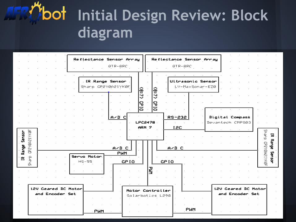
Initial Design Review: Block diagram
Initial Design Review: Basic Design
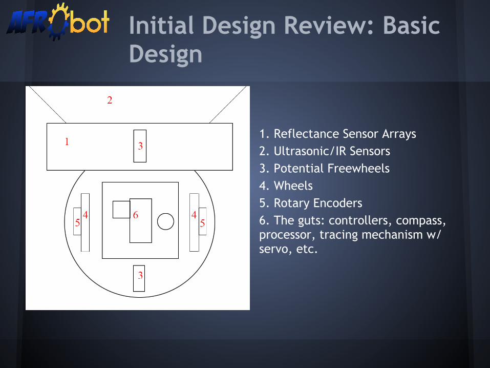
1. Reflectance Sensor Arrays2. Ultrasonic/IR Sensors3. Potential Freewheels4. Wheels5. Rotary Encoders6. The guts: controllers, compass, processor, tracing mechanism w/ servo, etc.

Parts: Digital Compass
● Devantech CMPS03 Magnetic Compass Module○ 0.1 degrees of resolution and 3 to 4 degrees of
accuracy○ Outputs heading via PWM or I2C○ 5V voltage only○ Specifically designed for use in robots as navigation
aid○ $44.61 @ www.robotshop.com

Parts: Reflectance Sensor Arrays
● QTR-8RC Reflectance Sensor Array○ Sensing distance: 3-9.5mm○ Interface directly to GPIO of microcontroller○ Operating voltage: 3.3-5.0 V○ $14.95 @ www.pololu.com
● GP2A240LCS0F○ Sensing distance: 2-22mm○ Interface directly to GPIO of microcontroller○ Operating voltage: 4.75-5.25 V○ $5.20 @ www.digikey.com
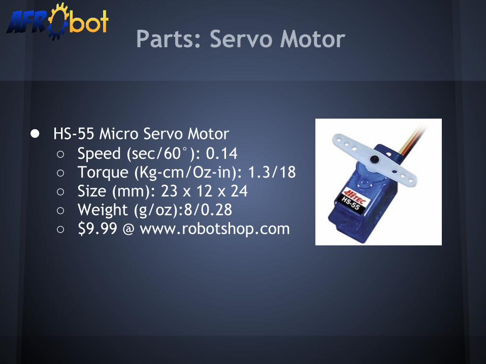
● HS-55 Micro Servo Motor○ Speed (sec/60°): 0.14○ Torque (Kg-cm/Oz-in): 1.3/18○ Size (mm): 23 x 12 x 24○ Weight (g/oz):8/0.28○ $9.99 @ www.robotshop.com
Parts: Servo Motor

● Maxbotix LV-MaxSonar-EZ0○ Object avoidance○ Detects objects of distance from 0 to 6.45 meters.
(0 to ~21 ft).○ RS-232○ 2.5 - 5.5V, at 5V - 3mA○ $26.95 @ www.robotshop.com
Parts: Ultrasonic Sensor
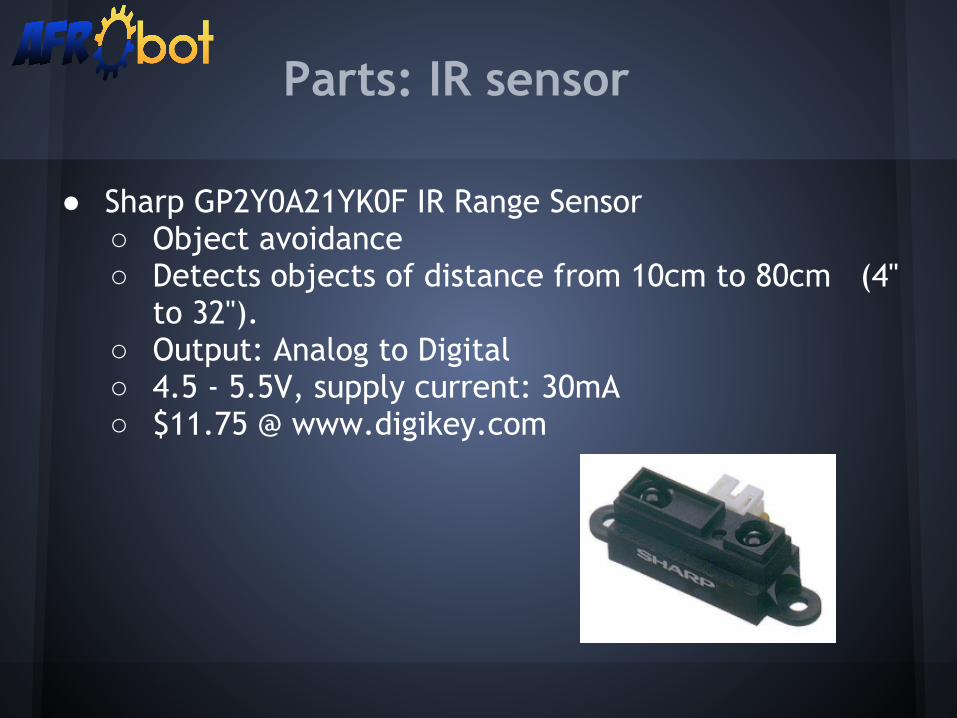
● Sharp GP2Y0A21YK0F IR Range Sensor○ Object avoidance ○ Detects objects of distance from 10cm to 80cm (4''
to 32'').○ Output: Analog to Digital ○ 4.5 - 5.5V, supply current: 30mA○ $11.75 @ www.digikey.com
Parts: IR sensor

● 2x Pololu 12V Metal Brushless DC Gear Motors○ $39.95 each○ 19:1 Gear Ratio○ 6mm diameter output shaft○ Integrated 2-Channel Hall Effect Quadrature
Encoder○ Forward/Backward/Brake/Pivot
Parts: Motors
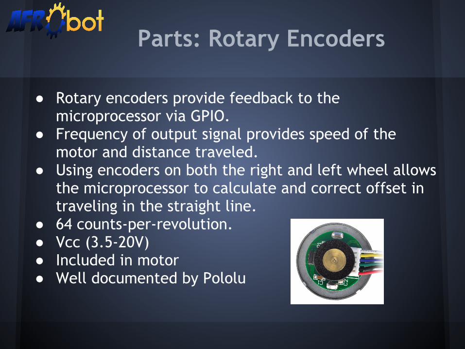
● Rotary encoders provide feedback to the microprocessor via GPIO.
● Frequency of output signal provides speed of the motor and distance traveled.
● Using encoders on both the right and left wheel allows the microprocessor to calculate and correct offset in traveling in the straight line.
● 64 counts-per-revolution.● Vcc (3.5-20V)● Included in motor● Well documented by Pololu
Parts: Rotary Encoders

● Solarbotics L298 Compact Dual Motor Driver Kit○ $18.28○ 6-50V Output○ Up to 4A total output current○ Allow us to independently control both motors with
a single chip○ Well documented○ Used by past 189 Capstone Projects
Parts:Motor Controller
Initial Design Review: Preliminary Bill of Materials
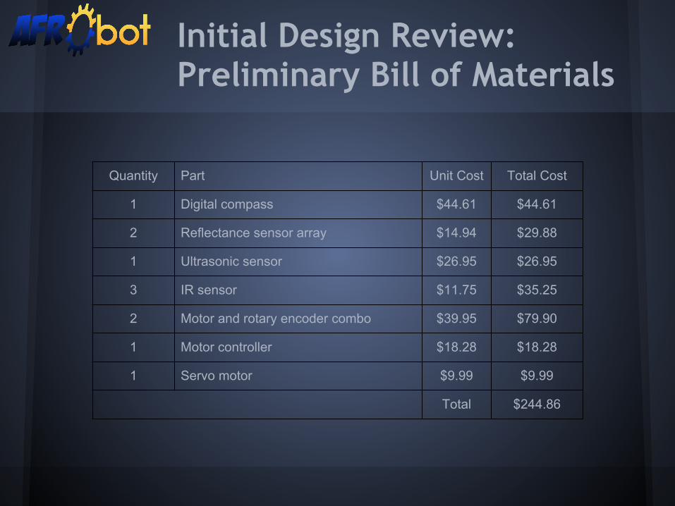
Quantity Part Unit Cost Total Cost
1 Digital compass $44.61 $44.61
2 Reflectance sensor array $14.94 $29.88
1 Ultrasonic sensor $26.95 $26.95
3 IR sensor $11.75 $35.25
2 Motor and rotary encoder combo $39.95 $79.90
1 Motor controller $18.28 $18.28
1 Servo motor $9.99 $9.99
Total $244.86
● Motor control ○ Keeping the bot in a straight path to avoid rough
traces.● Reflectance Sensor Array
○ Being able to detect a line in an outdoor environment and use that data to accurately position AFRObot. ■ Currently looking into camera modules.
Initial Design Review: Critical Elements

Initial Design Review: Schedule
11/18 - 11/24PCB layout - M5 (11/18 - 12/07)
Low level hardware implementation - M4 (11/11 - 11/28)
Verilog functional and timing simulations
Details of intended software structure
Lowest-level hardware-software interaction
MAKEPART
11/14 - 12/01Milestone #4 - (11/28)
PCB layout - Milestone #5 (11/18 - 12/07)
12/02 - 12/08Critical Design Review - (12/03)
Milestone #5 - (12/07)
12/9 - 12/15Finals
12/16 - 01/6/2013WINTER BREAK!!!
10/21 - 10/27
IDR - (10/24)
Purchase parts - (10/24)
System-level Design - M3 (10/24 - 10/31)
Component selection - BOM
Collection of data sheets
Software!
Develop parts test plan - (10/24 - 11/03)
10/28 - 11/03
Milestone #3 - (10/31)
Test parts (10/28 - 11/03)
11/04 - 11/10
Preliminary Design Review - (11/05)
11/11 - 11/17
Low level hardware implementation - M4 (11/11 - 11/28)
Verilog functional and timing simulations
lowest-level hardware-software interaction
MAKEPART

Questions?Suggestions?


