+ All Categories
Home > Documents > Autonomous Mobile Robotsallen/F15/NOTES/Lecture_5_rev_2.pdf · 2015-08-25 · Autonomous Mobile...

Autonomous Mobile Robotsallen/F15/NOTES/Lecture_5_rev_2.pdf · 2015-08-25 · Autonomous Mobile...

Date post: 29-May-2020
Category:
Upload: others
View: 5 times
Download: 0 times
Share this document with a friend
34
Autonomous Mobile Robots Autonomous Systems Lab Zürich Perception Sensors Vision Uncertainties, Line extraction from laser scans "Position" Global Map Perception Motion Control Cognition Real World Environment Localization Path Environment Model Local Map
Transcript

Autonomous Mobile Robots

Autonomous Systems LabZürich

PerceptionSensors

Vision

Uncertainties, Line extraction from laser scans

"Position"

Global Map

Perception Motion Control

Cognition

Real WorldEnvironment

Localization

PathEnvironment Model

Local Map

© R. Siegwart , D. Scaramuzza and M.Chli, ETH Zurich - ASL

One picture, a thousand words

Of all our senses, vision is the most powerful in aiding our perception of

the 3D world around us.

Retina is ~1000m2. Contains millions of photoreceptors(120 mil. rods and 7 mil. Cones for colour sampling)

Provides enormous amount of information: data-rate of ~3GBytes/s

a large proportion of our brain power is dedicated to processing the

signals from our eyes

4.2 - Perception - Vision4.2

2

http://webvision.med.utah.edu/sretina.html

© R. Siegwart , D. Scaramuzza and M.Chli, ETH Zurich - ASL

Human Visual Capabilities

4.2 - Perception - Vision4.2

3

Our visual system is very sophisticated

Humans can interpret images successfully under a wide range of

conditions – even in the presence of very limited cues

© R. Siegwart , D. Scaramuzza and M.Chli, ETH Zurich - ASL

Vision for Robotics

Enormous descriptability of images

a lot of data to process (human vision involves 60 billion neurons!)

Not sensible to copy the biology, but learn from it

Capture light Convert to digital image

Process to get „salient‟ information

Vision is increasingly popular as a sensing

modality:

compactness,

compatibility,

low cost, …

HW advances necessary to support the

processing of images

4.2 - Perception - Vision4.2

4

Image: Nicholas M. Short

© R. Siegwart , D. Scaramuzza and M.Chli, ETH Zurich - ASL

Computer Vision

4c - Perception - Vision4c

5

© R. Siegwart , D. Scaramuzza and M.Chli, ETH Zurich - ASL

Connection to other disciplines

4c - Perception - Vision4c

6

© R. Siegwart , D. Scaramuzza and M.Chli, ETH Zurich - ASL

Applications of Computer Vision

4c - Perception - Vision4c

7

© R. Siegwart , D. Scaramuzza and M.Chli, ETH Zurich - ASL

4c - Perception - Vision4c

8 Applications of Computer Vision

© R. Siegwart , D. Scaramuzza and M.Chli, ETH Zurich - ASL

Today‟s Topics

Section 4.2 in the book

Pinhole Model

Perspective Projection

Stereo Vision

Optical Flow

Color Tracking

4c

9

4c - Perception - Vision

© R. Siegwart , D. Scaramuzza and M.Chli, ETH Zurich - ASL

The camera

4c - Perception - Vision4c

10

Sony Cybershot WX1

© R. Siegwart , D. Scaramuzza and M.Chli, ETH Zurich - ASL

filmobject

How do we see the world?

Place a piece of film in front of an object

Do we get a reasonable image?

4c - Perception - Vision4c

11

© R. Siegwart , D. Scaramuzza and M.Chli, ETH Zurich - ASL

filmobject

Pinhole camera

Add a barrier to block off most of the rays

This reduces blurring

The opening known as the aperture

4c - Perception - Vision4c

12

barrier

© R. Siegwart , D. Scaramuzza and M.Chli, ETH Zurich - ASL

Camera obscura

Basic principle known to Mozi (470-

390 BC), Aristotle (384-322 BC)

Drawing aid for artists: described by

Leonardo da Vinci (1452-1519)

Depth of the room (box) is the

effective focal length

4c - Perception - Vision4c

13

© R. Siegwart , D. Scaramuzza and M.Chli, ETH Zurich - ASL

Pinhole camera model

Pinhole model:

Captures pencil of rays – all rays through a single point

The point is called Center of Projection or Optical Center

The image is formed on the Image Plane

Slide by Steve Seitz

4c - Perception - Vision4c

14

© R. Siegwart , D. Scaramuzza and M.Chli, ETH Zurich - ASL

Home-made pinhole camera

http://www.debevec.org/Pinhole/

Why soblurry?

4c - Perception - Vision4c

15

© R. Siegwart , D. Scaramuzza and M.Chli, ETH Zurich - ASL

Shrinking the aperture

Why not make the aperture as small as possible?

Less light gets through (must increase the exposure)

Diffraction effects…

Slide by Steve Seitz

4c - Perception - Vision4c

17

© R. Siegwart , D. Scaramuzza and M.Chli, ETH Zurich - ASL

filmobject Lens

Solution: adding a lens

A lens focuses light onto the film

Rays passing through the center are not deviated

4c - Perception - Vision4c

18

CS4733 Class Notes, Stereo Imaging

Figure 1: Perspective imaging geometry showing relationship between 3D points and image planepoints.

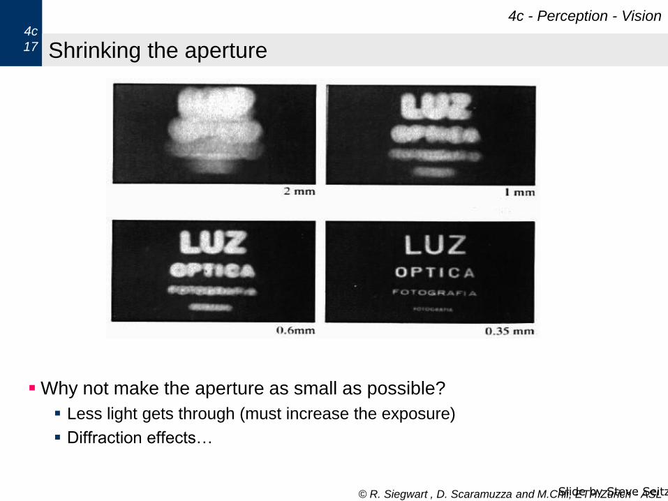
1 Stereo Imaging: Camera Model and Perspective Transform

We typically use a pinhole camera model that maps points in a 3-D camera frame to a 2-D projectedimage frame. In figure 1, we have a 3D camera coordinate frame Xc, Yc, Zc with origin Oc, and animage coordinate frame Xi, Yi, Zi with origin Oi. The focal length is f . Using similar triangles, wecan relate image plane and world space coordinates. We have a 3D point P = (X, Y, Z) which projectsonto the image plane at P ′ = (x, y, f). Oc is the origin of the camera coordinate system, known as thecenter of projection (COP) of the camera.

Using similar triangles, we can write down the folowing relationships:

X

x=

Z

f;

Y

y=

Z

f; x = f ·

X

Z; y = f ·

Y

Z

If f = 1, note that perspective projection is just scaling a world coordinate by its Z value. Alsonote that all 3D points along a line from the COP through a designated position (x, y) on the imageplane will have the same image plane coordinates.

1

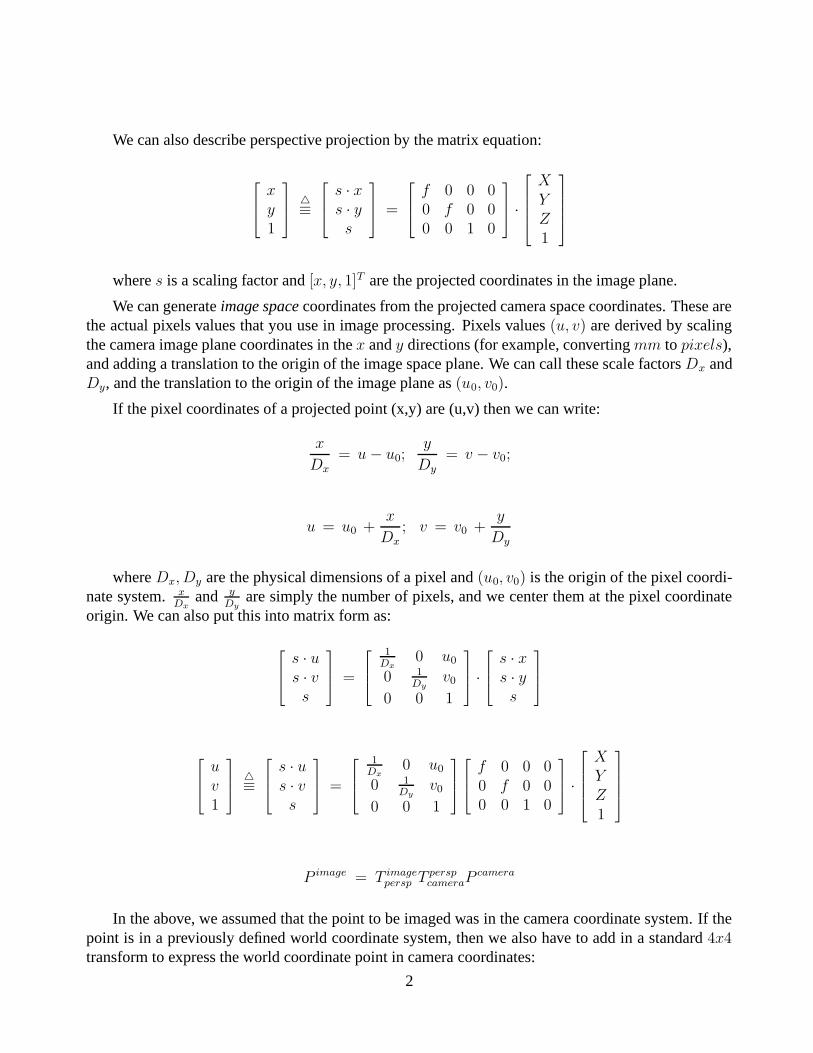
We can also describe perspective projection by the matrix equation:

x

y

1

4

s · x

s · y

s

=

f 0 0 00 f 0 00 0 1 0

·

X

Y

Z

1

where s is a scaling factor and [x, y, 1]T are the projected coordinates in the image plane.

We can generate image space coordinates from the projected camera space coordinates. These arethe actual pixels values that you use in image processing. Pixels values (u, v) are derived by scalingthe camera image plane coordinates in the x and y directions (for example, converting mm to pixels),and adding a translation to the origin of the image space plane. We can call these scale factors Dx andDy, and the translation to the origin of the image plane as (u0, v0).

If the pixel coordinates of a projected point (x,y) are (u,v) then we can write:

x

Dx

= u − u0;y

Dy

= v − v0;

u = u0 +x

Dx

; v = v0 +y

Dy

where Dx, Dy are the physical dimensions of a pixel and (u0, v0) is the origin of the pixel coordi-nate system. x

Dx

and y

Dy

are simply the number of pixels, and we center them at the pixel coordinateorigin. We can also put this into matrix form as:

s · u

s · v

s

=

1

Dx

0 u0

0 1

Dy

v0

0 0 1

·

s · x

s · y

s

u

v

1

4

s · u

s · v

s

=

1

Dx

0 u0

0 1

Dy

v0

0 0 1

f 0 0 00 f 0 00 0 1 0

·

X

Y

Z

1

P image = T imagepersp T persp

cameraPcamera

In the above, we assumed that the point to be imaged was in the camera coordinate system. If thepoint is in a previously defined world coordinate system, then we also have to add in a standard 4x4transform to express the world coordinate point in camera coordinates:

2

u

v

1

=

s · u

s · v

s

=

1

Dx

0 u0

0 1

Dy

v0

0 0 1

f 0 0 00 f 0 00 0 1 0

r11 r12 r13 txr21 r22 r23 tyr31 r32 r33 tz0 0 0 1

·

wXwYwZ

1

P image = T imagepersp T persp

cameraTcameraworld P world

Summing all this up, we can see that we need to find the following information to transform anarbitrary 3D world point to a designated pixel in a computer image:

• 6 parameters that relate the 3D world point to the 3D camera coordinate system (standard 3translation and 3 rotation): (R, T )

• Focal Length of the camera: f

• Scaling factors in the x and y direcitons on the image plane: (Dx, Dy)

• Translation to the origin of the image plane: (u0, v0).

This is 11 parameters in all. We can break these parameters down into Extrinsic parameterswhich are the 6-DOF transform between the camera coordinate system and the world coordinatesystem, and the Intrinsic parameters which are unique to the actual camera being used, andinclude the focal length, scaling factors, and location of the origin of the pixel coordinate system.

2 Camera Calibration

Camera calibration is used to find the mapping from 3D to 2D image space coordinates. There are 2approaches:

• Method I: Find both extrinsic and intrinsic parameters of the camera system. However, this canbe difficult to do. The instinsic parameters of the camera may be unknown (i.e. focal length,pixel dimension) and the 6-DOF transform also may be difficult to calculate directly.

• Method 2: An easier method is the “Lumped” transform. Rather than finding individual param-eters, we find a composite matrix that relates 3D to 2D. Given the equation below:

P image = T imagepersp T persp

cameraTcameraworld P world

we can lump the 3 T matrices into a 3x4 calibration matrix C:

P image = C P world

C = T imagepersp T persp

cameraTcameraworld

3

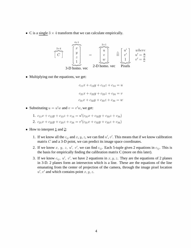
• C is a single 3 × 4 transform that we can calculate empirically.

3×4︷ ︸︸ ︷[

C]

4×1︷ ︸︸ ︷

x

y

z

1

︸ ︷︷ ︸

3-D homo. vec

=

3×1︷ ︸︸ ︷

u

v

w

︸ ︷︷ ︸

2-D homo. vec

4

u′

v′

1

︸ ︷︷ ︸

Pixels

where

u′ = uw

v′ = vw

• Multiplying out the equations, we get:

c11x + c12y + c13z + c14 = u

c21x + c22y + c23z + c24 = v

c31x + c32y + c33z + c34 = w

• Substituting u = u′w and v = v′w, we get:

1. c11x + c12y + c13z + c14 = u′(c31x + c32y + c33z + c34)

2. c21x + c22y + c23z + c24 = v′(c31x + c32y + c33z + c34)

• How to interpret 1 and 2:

1. If we know all the cij and x, y, z, we can find u′, v′. This means that if we know calibrationmatrix C and a 3-D point, we can predict its image space coordinates.

2. If we know x, y, z, u′, v′, we can find cij. Each 5-tuple gives 2 equations in cij . This isthe basis for empirically finding the calibration matrix C (more on this later).

3. If we know cij, u′, v′, we have 2 equations in x, y, z. They are the equations of 2 planesin 3-D. 2 planes form an intersecton which is a line. These are the equations of the lineemanating from the center of projection of the camera, through the image pixel locationu′, v′ and which contains point x, y, z.

4

• We can set up a linear system to solve for cij: AC = B

x1 y1 z1 1 0 0 0 0 −u′

1x −u′

1y −u′

1z

0 0 0 0 x1 y1 z1 1 −v′1x −v′1y −v′1z

x2 y2 z2 1 0 0 0 0 −u′

2x −u′

2y −u′

2z

0 0 0 0 x2 y2 z2 1 −v′2x −v′2y −v′2z

.

.

.

.

.

.

.

c11

c12

c13

c14

c21

c22

c23

c24

c31

c32

c33

︸ ︷︷ ︸

We can assume c34=1

=

u′

1

v′1u′

2

v′2u′

3

v′3.

.

.

u′

N

v′N

• Each set of points x, y, z, u′, v′ yields 2 equations in 11 unknowns (the cij’s).

• To solve for C, A needs to be invertible (square). We can overdetermine A and find a Least-Squares fit for C by using a pseudo-inverse solution.

If A is N × 11, where N > 11,AC = B

AT AC = AT B

C = (AT A)−1

︸ ︷︷ ︸

pseudo inverse

AT B

3 COMPUTATIONAL STEREO

Stereopsis is an identified human vision process. It is a passive, simple procedure that is robust tochanges in lighting, scale, etc. Humans can fuse random dot stereograms that contain no high-levelinformation about the objects in the fused images, yet they can infer depth from these stereograms.The procedure is:

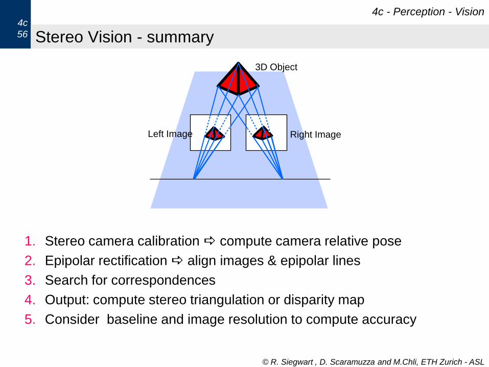
• Camera-Modeling/Image-acquisition

• Feature extraction - identify edges, corners, regions etc.

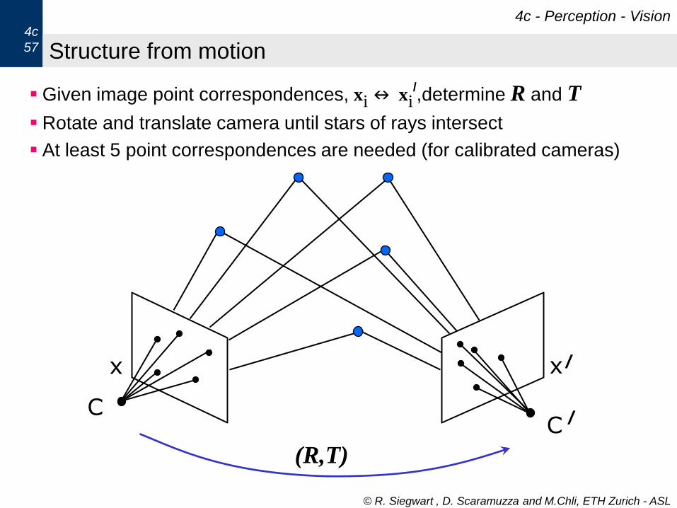
• Matching/Correspondence - find same feature in both images

• Compute depth from matches - use calibration information to back project rays from each cam-era and intersect them (triangulation)

5

• Interpolate surfaces - Matches are sparse, and constraints such as smoothness of surfaces areneeded to “fill in” the depth between match points.

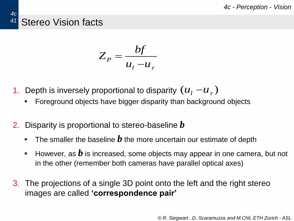
Camera Modeling: An important consideration in computational stereo is the setup of the cam-eras. The baseline between the camera centers determines the accuracy of the triangulation. Largebaseline means more accuracy; however as the baseline gets larger, the same physical event in eachimage may not be found.

The cameras also have to be calibrated and registered. Calibration is relatively straightforward,and a variety of methods exist. Some methods extend the simple least squares model we discussed toinclude non-linear effects of lens distortion (particularly true with short a focal length lens).

Registration is needed to make use of the epipolar constraint. This constraint consists of a planethat includes both camera’s optical centers and a point in 3-D space. This epilolar plane intersectsboth image planes in a straight line.

Feature Extraction: Identifying features in each image that can be matched is an important partof the stereo process. It serves 2 purposes: 1) data reduction so we are not forced to deal with everysingle pixel as a potential match, and 2) stability - features are seen to be more stable than a singlegray level pixel.

There are 2 approaches: feature-based methods which find primitives such as edges, corners, lines,arcs in each image and match them; and area-based methods that identify regions or areas of pixelsthat can be matched using correlation based methods. Sometimes both methods are used, with feature-based methods proposing a match and area-based methods centered on the feature used to verify it.

Correspondence: The heart of the stereo problem is a search procedure. Given a pixel in image1, it can potentially match each of N 2 pixels in the other image. To cut down this search space,cameras are often registered along scan lines. This means that he epipolar plane intersects each imageplane along the same scan line. A pixel in image 1 can now potentially match only a pixel along thecorresponding scan line in image 2, reducing the search from O ( N 2 ) to O ( N ). The match criteriacan include not only the location of a feature like an edge, but also the edge direction and polarity.

Problems in Matching: A number of problems occur during matching to create false matches:These are occlusions, periodic features such as texture, homogeneous regions without features, base-line separation errors, and misregistered images. Stereo can usually only provide sparse 3-D data ateasily identified feature points.

6

© R. Siegwart , D. Scaramuzza and M.Chli, ETH Zurich - ASL

How do we measure distances with cameras?

4c - Perception - Vision4c

37

Impossible to capture 3D structure from a single image. We can only

deduct the ray on which each image point lies.

Observe scene from 2 different viewpoints solve for the intersection of

the rays and recover the 3D structure

Right Image

3D Object

Left Image

© R. Siegwart , D. Scaramuzza and M.Chli, ETH Zurich - ASL

Disparity in the human retina

4c - Perception - Vision4c

38

© R. Siegwart , D. Scaramuzza and M.Chli, ETH Zurich - ASL

How do we measure distances with cameras?

4c - Perception - Vision4c

39

Structure from stereo (Stereo-vision):

use two cameras with known relative position and orientation

Structure from motion:

use a single moving camera: both 3D structure and camera motion

can be estimated up to a scale

© R. Siegwart , D. Scaramuzza and M.Chli, ETH Zurich - ASL

Stereo Vision - The simplified case

The simplified case is an ideal case. It assumes that both cameras are

identical and are aligned on a horizontal axis

4c - Perception - Vision4c

40

f

bX

Z

urul

CrCl

P

r

P

P

l

P

Xb

u

Z

f

X

u

Z

f

From Similar Triangles:

rl

Puu

bfZ

Baselinedistance between the optical centers of

the two cameras

Disparitydifference in image location of the projection

of a 3D point in two image planes

),,( PPP ZYXP

© R. Siegwart , D. Scaramuzza and M.Chli, ETH Zurich - ASL

Stereo Vision facts

1. Depth is inversely proportional to disparity

Foreground objects have bigger disparity than background objects

2. Disparity is proportional to stereo-baseline b

The smaller the baseline b the more uncertain our estimate of depth

However, as b is increased, some objects may appear in one camera, but not

in the other (remember both cameras have parallel optical axes)

3. The projections of a single 3D point onto the left and the right stereo

images are called „correspondence pair‟

4c - Perception - Vision4c

41

rl

Puu

bfZ

)( rl uu

© R. Siegwart , D. Scaramuzza and M.Chli, ETH Zurich - ASL

Correspondence Problem

Which patch in the Left image, corresponds to the projection of the same 3D

scene point on the Right image?

Correspondence search could be done by testing the query-patches at all pixel

positions in the other image. Typical similarity measures are the Cross-

Correlation and Sum of Squared Differences

Exhaustive image search can be computationally very expensive! Is there a way

to make the correspondence search 1-dimensional?

4c - Perception - Vision4c

44

© R. Siegwart , D. Scaramuzza and M.Chli, ETH Zurich - ASL

Epipolar Geometry

Triangulating 2 rays from image correspondences

Impose the epipolar constraint to aid matching: search for a

correspondence along the epipolar line

The epipolar plane is defined by a 3D point P and the optical centers.

4c - Perception - Vision4c

45

),,( zyxP

),( 111 vup ),( 222 vup

1C 2C1E 2E

epipoles

Epipolar Line 2Epipolar Line 1

© R. Siegwart , D. Scaramuzza and M.Chli, ETH Zurich - ASL

Correspondence Problem: Epipolar Constraint

Thanks to the epipolar constraint, conjugate points can be searched

along epipolar lines: this reduces the computational cost to 1 dimension!

4c - Perception - Vision4c

46

© R. Siegwart , D. Scaramuzza and M.Chli, ETH Zurich - ASL

Stereo Vision Output 1 – Disparity map

Left image Right image

Disparity map

Find the correspondent points of all

image pixels of the original images

Compute the disparity for each pair

of correspondences

Disparity map: holds the disparity

value at every pixel

Usually visualized as grey-scale

images. If lighter color corresponds

to larger disparities, then objects

closer to the camera appear lighter,

than those further away.

4c - Perception - Vision4c

55

© R. Siegwart , D. Scaramuzza and M.Chli, ETH Zurich - ASL

Stereo Vision - summary

1. Stereo camera calibration compute camera relative pose

2. Epipolar rectification align images & epipolar lines

3. Search for correspondences

4. Output: compute stereo triangulation or disparity map

5. Consider baseline and image resolution to compute accuracy

4c - Perception - Vision4c

56

Right Image

3D Object

Left Image

© R. Siegwart , D. Scaramuzza and M.Chli, ETH Zurich - ASL

Structure from motion

Given image point correspondences, xin xi/,determine R and T

Rotate and translate camera until stars of rays intersect

At least 5 point correspondences are needed (for calibrated cameras)

4c - Perception - Vision4c

57

x x/

CC

/

(R,T)


Recommended