Communications on Applied Electronics (CAE) – ISSN : 2394-4714 Foundation of Computer Science FCS, New York, USA Volume 7 – No.4, July 2017 – www.caeaccess.org 12 Autonomous, Surveillance Fire Extinguisher Robotic Vehicle with Obstacle Detection and Bypass using Arduino Microcontroller Sumanta Chatterjee Asst. Professor JIS College of Engineering Kalyani, WB, India Apurba Paul Asst. Professor JIS College of Engineering Kalyani, WB, India ABSTRACT A robotic vehicle has to move autonomously avoiding the obstacles and at the same time finding and tracking flame sources and extinguishing them. In addition to that it has to send the live feed of the surrounding. For achieving this objective the implementation has been divided into various modules such as avoiding obstacles, fire detection, fire extinguishing and wireless transmission of the visual. Keywords Microcontroller, Flame Sensor, Ultrasonic Sensor, Motor Driver, IP Webcam 1. INTRODUCTION The objectives of the project are to develop a vehicle that can run autonomously by avoiding the obstacles in its path. At the same time it should be able to track and find the fire source and extinguish without direct contact. Then the fire source can be extinguished. Apart from this live surveillance feed via the wireless camera to a PC will enable to view the surrounding. This project is an integration of various features: 1.1 Fire Detection The fire is detected using 3 flame sensors, placed in three sides- front, left and right. 1.2 Fire Extinguishing For the purpose of extinguishing the fire, a fire extinguisher can is used. It is controlled using a linear actuator. 1.3 Wireless Camera The objective of the camera is to transmit the live feed to a workstation such as laptop or PC. The cost effective solution was to make use of an Arduino camera module with Wi-Fi module. As a result the camera feeds obtained could be transmitted anywhere. 1.4Avoiding Obstacle On the way to the detected fire spot if this vehicle finds any obstacle, it can bypass that obstacle. This is achieved using ultrasonic sensors. After avoiding obstacles the vehicle reaches the exact spot. 2. HARDWARE COMPONENTS 2.1 FlameSensor This Flame Sensor can be used to detect fire source or other light sources of the wave length in the range of 760nm - 1100 nm. It is based on the YG1006 sensor which is a high speed and high sensitive NPN silicon phototransistor. Due to its black epoxy, the sensor is sensitive to infrared radiation. In fire-fighting robot game, the sensor plays a very important role; it can be used as a robot eyes to find the fire source. When detected the flame the Signal LED will on and the D0 output LOW voltage level. Features High Photo Sensitivity Fast Response Time Sensitivity adjustable Specification Working voltage: 3.3v-5v Detect range: 60 degrees Digital/Analog output On-board LM393 chip Dimension of the board: 3.2cm x 1.4cm Figure 1: Flame Sensor 2.2 Ultrasonic Sensor HC-SR04 Ultrasonic sensor are also known as transceivers as when they both send and receive. They work on the principle similar to radar or sonar. Active ultrasonic sensors generate high frequency sound waves and evaluate the echo which is received back by the sensor, measuring the time interval between sending the signal and receiving the echo to determine the distance to an object. Passive ultrasonic sensors are basically microphones that detect ultrasonic noise that is present under certain conditions. The range of the target is determined by the "time lagging" between transmitted pulse and the received "echo". Generally microwave and ultrasonic frequencies are used in radars.HC-SR04 ultrasonic sensor works similar to the radar mechanism but in a simplified manner. This sensor consists of four pins as following:
Transcript
Communications on Applied Electronics (CAE) – ISSN : 2394-4714
Foundation of Computer Science FCS, New York, USA
Volume 7 – No.4, July 2017 – www.caeaccess.org
12
Autonomous, Surveillance Fire Extinguisher Robotic
Vehicle with Obstacle Detection and Bypass using
Arduino Microcontroller
Sumanta Chatterjee Asst. Professor
JIS College of Engineering Kalyani, WB, India
Apurba Paul Asst. Professor
JIS College of Engineering Kalyani, WB, India
ABSTRACT
A robotic vehicle has to move autonomously avoiding the
obstacles and at the same time finding and tracking flame
sources and extinguishing them. In addition to that it has to
send the live feed of the surrounding. For achieving this
objective the implementation has been divided into various
modules such as avoiding obstacles, fire detection, fire
extinguishing and wireless transmission of the visual.
Keywords
Microcontroller, Flame Sensor, Ultrasonic Sensor, Motor
Driver, IP Webcam
1. INTRODUCTION The objectives of the project are to develop a vehicle that can
run autonomously by avoiding the obstacles in its path. At the
same time it should be able to track and find the fire source
and extinguish without direct contact. Then the fire source can
be extinguished. Apart from this live surveillance feed via the
wireless camera to a PC will enable to view the surrounding.
This project is an integration of various features:
1.1 Fire Detection
The fire is detected using 3 flame sensors, placed in three
sides- front, left and right.
1.2 Fire Extinguishing For the purpose of extinguishing the fire, a fire extinguisher
can is used. It is controlled using a linear actuator.
1.3 Wireless Camera The objective of the camera is to transmit the live feed to a
workstation such as laptop or PC. The cost effective solution
was to make use of an Arduino camera module with Wi-Fi
module. As a result the camera feeds obtained could be
transmitted anywhere.
1.4Avoiding Obstacle On the way to the detected fire spot if this vehicle finds any
obstacle, it can bypass that obstacle. This is achieved using
ultrasonic sensors. After avoiding obstacles the vehicle
reaches the exact spot.
2. HARDWARE COMPONENTS
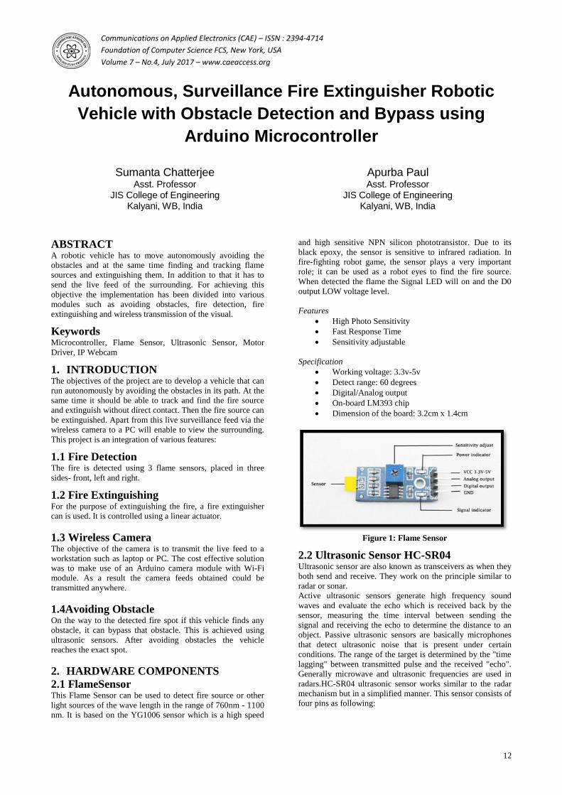
2.1 FlameSensor This Flame Sensor can be used to detect fire source or other
light sources of the wave length in the range of 760nm - 1100
nm. It is based on the YG1006 sensor which is a high speed
and high sensitive NPN silicon phototransistor. Due to its
black epoxy, the sensor is sensitive to infrared radiation. In
fire-fighting robot game, the sensor plays a very important
role; it can be used as a robot eyes to find the fire source.
When detected the flame the Signal LED will on and the D0
output LOW voltage level.
Features
High Photo Sensitivity
Fast Response Time
Sensitivity adjustable
Specification
Working voltage: 3.3v-5v
Detect range: 60 degrees
Digital/Analog output
On-board LM393 chip
Dimension of the board: 3.2cm x 1.4cm
Figure 1: Flame Sensor
2.2 Ultrasonic Sensor HC-SR04
Ultrasonic sensor are also known as transceivers as when they
both send and receive. They work on the principle similar to
radar or sonar.
Active ultrasonic sensors generate high frequency sound
waves and evaluate the echo which is received back by the
sensor, measuring the time interval between sending the
signal and receiving the echo to determine the distance to an
object. Passive ultrasonic sensors are basically microphones
that detect ultrasonic noise that is present under certain
conditions. The range of the target is determined by the "time
lagging" between transmitted pulse and the received "echo".
Generally microwave and ultrasonic frequencies are used in
radars.HC-SR04 ultrasonic sensor works similar to the radar
mechanism but in a simplified manner. This sensor consists of
four pins as following:
Communications on Applied Electronics (CAE) – ISSN : 2394-4714
Foundation of Computer Science FCS, New York, USA
Volume 7 – No.4, July 2017 – www.caeaccess.org
13
Table 1: Pin details of HC-SR04
Vcc Connect to 5V DC
Trigger Pulse input that triggers
the sensor
Echo
Indicates the reception of
echo from the target
Gnd Ground final
Figure 2: Ultrasonic Sensor
2.3 Motor IC L293D is a typical Motor driver or Motor Driver IC which
allows DC motor to drive on either direction. L293D is a 16-
pin IC which can control a set of two DC motors
simultaneously in any direction.
Figure 3. L293D Pin Diagram
The 4 input pins in L293D i.e. Pin 2 and Pin 7will regulate the
rotation of motor connected across left side and Pin 15 and
Pin 10 will regulate the rotation of motor connected across the
right side. The motors are rotated on the basis of the inputs
provided across the input pins as LOGIC 0 or LOGIC 1.
Consider a Motor is connected on left side output pins (pin
3,6). For rotating the motor in clockwise direction the input
pins has to be provided with Logic 1 and Logic 0.
Table 2: Pin details of L293D
Pin 2 Pin 7 Rotation
1 0 Clockwise
0 1 Anticlockwise
0 0 Stop
1 1 Stop
In a very similar way a motor can also operated across input
pin 15, 10 for motor on the right hand side.
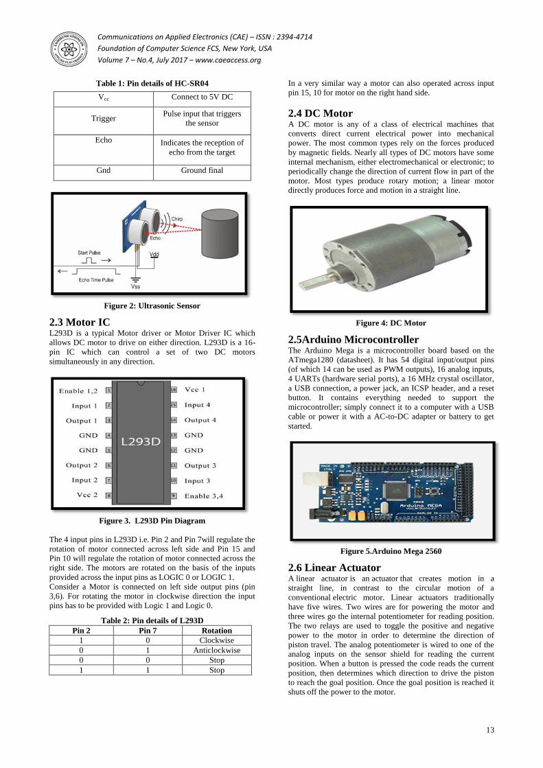
2.4 DC Motor A DC motor is any of a class of electrical machines that
converts direct current electrical power into mechanical
power. The most common types rely on the forces produced
by magnetic fields. Nearly all types of DC motors have some
internal mechanism, either electromechanical or electronic; to
periodically change the direction of current flow in part of the
motor. Most types produce rotary motion; a linear motor
directly produces force and motion in a straight line.
Figure 4: DC Motor
2.5Arduino Microcontroller The Arduino Mega is a microcontroller board based on the
ATmega1280 (datasheet). It has 54 digital input/output pins
(of which 14 can be used as PWM outputs), 16 analog inputs,
4 UARTs (hardware serial ports), a 16 MHz crystal oscillator,
a USB connection, a power jack, an ICSP header, and a reset
button. It contains everything needed to support the
microcontroller; simply connect it to a computer with a USB
cable or power it with a AC-to-DC adapter or battery to get
started.
Figure 5.Arduino Mega 2560
2.6 Linear Actuator
A linear actuator is an actuator that creates motion in a
straight line, in contrast to the circular motion of a
conventional electric motor. Linear actuators traditionally
have five wires. Two wires are for powering the motor and
three wires go the internal potentiometer for reading position.
The two relays are used to toggle the positive and negative
power to the motor in order to determine the direction of
piston travel. The analog potentiometer is wired to one of the
analog inputs on the sensor shield for reading the current
position. When a button is pressed the code reads the current
position, then determines which direction to drive the piston
to reach the goal position. Once the goal position is reached it
shuts off the power to the motor.
Communications on Applied Electronics (CAE) – ISSN : 2394-4714
Foundation of Computer Science FCS, New York, USA
Volume 7 – No.4, July 2017 – www.caeaccess.org
14
Figure 6: Linear Actuator
2.7Arduino Camera Module Arduino camera module, adopted the Surveillance cameras
digital image processing chip-OV0706, specially designed for
image acquisition and processing application, based on TTL
communication interface, very convenient to connect with
Arduino controller, able to read image and data via UART
serial port, and then perform some image processing.
Figure 7: Arduino Camera Module
2.8WiFi Module The ESP8266 Wi-Fi Module is a self-contained SOC with
integrated TCP/IP protocol stack that can give any
microcontroller access to your Wi-Fi network. The ESP8266
is capable of communicating with other microcontroller using
TX, RX ports. Each ESP8266 module comes pre-programmed
with an AT command set firmware. It connects to the internet
using IEEE 802.11 b/g/n standard.
Figure 8: ESP8266 Wi-Fi Module
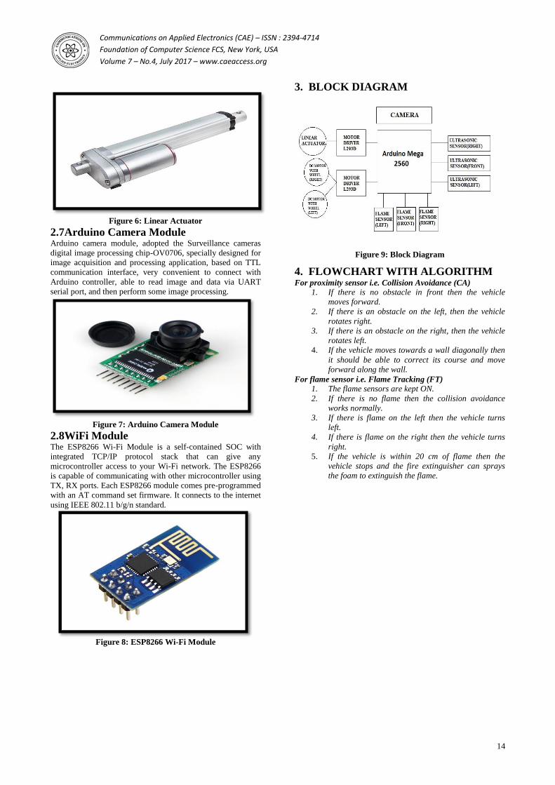
3. BLOCK DIAGRAM
Figure 9: Block Diagram
4. FLOWCHART WITH ALGORITHM For proximity sensor i.e. Collision Avoidance (CA)
1. If there is no obstacle in front then the vehicle
moves forward.
2. If there is an obstacle on the left, then the vehicle
rotates right.
3. If there is an obstacle on the right, then the vehicle
rotates left.
4. If the vehicle moves towards a wall diagonally then
it should be able to correct its course and move
forward along the wall.
For flame sensor i.e. Flame Tracking (FT)
1. The flame sensors are kept ON.
2. If there is no flame then the collision avoidance
works normally.
3. If there is flame on the left then the vehicle turns
left.
4. If there is flame on the right then the vehicle turns
right.
5. If the vehicle is within 20 cm of flame then the
vehicle stops and the fire extinguisher can sprays
the foam to extinguish the flame.
Communications on Applied Electronics (CAE) – ISSN : 2394-4714
Foundation of Computer Science FCS, New York, USA
Volume 7 – No.4, July 2017 – www.caeaccess.org
15
Figure 10: Flowchart of entire bot
5. CIRCUIT DIAGRAM In this circuit, the microcontroller is connected to two motor
drivers IC. One motor driver IC is used to control the DC
motors attached to the wheel. Another motor driver IC is used
to control the linear actuator. The three flame detectors are
connected to the analog pins of Arduino microcontroller. Also
the three ultrasonic sensors are also connected to the analog
pins of the Arduino microcontroller.
Module 1: Arduino Microcontroller with
Ultrasonic Sensors
Figure 11: Arduino Microcontroller with Ultrasonic
Sensors
Three ultrasonic sensors are used in front, left and right. The
pin connections are as follows:
Table 3: Pin connection of Ultrasonic Sensors with
Arduino Mega 2560
Sensor Sensor Pin No Arduino Pin No
Right Trigger A0
Echo A1
Front Trigger A4
Echo A5
Left Trigger A2
Echo A3
Module 2:ArduinoMicrocontroller with
Flame Sensors
Figure 12: Arduino Microcontroller with Flame Sensors
Three flame sensors are used in front, left and right. Here the
analog pin (A0) was used and the digital pin (D0) was left out.
The pin connections are as follows:
Table 4: Pin connection of flame sensors with Arduino
Mega 2560
Sensor Sensor Pin No Arduino Pin
No
Right A0 A8
Front A0 A6
Left A0 A7
Module 3: Arduino Microcontroller with
motor driver and wheel
Communications on Applied Electronics (CAE) – ISSN : 2394-4714
Foundation of Computer Science FCS, New York, USA
Volume 7 – No.4, July 2017 – www.caeaccess.org
16
Figure 13: Arduino Microcontroller with motor driver
and wheel.
In this module a motor driver is used to the control the two
DC motors attached to wheels. The pin connections are as
follows:
Table 5: Pin connection of L293D IC with Arduino Mega
2560
Motor L293D Pins Arduino
Pins
Left Motor 1 (enable pin) 10
2 (input 1) 8
7 (input 2) 9
Right
Motor
8 (enable pin) 11
12 (input 3) 12
13 (input 4) 13
Module 4: Arduino Microcontroller with
Camera Module
In this module the camera is interfaced with Arduino mega
microcontroller. The pin connections are as follows:
Table 6: Pin connection of OV0706 IC with Arduino Mega
2560
Camera
Module Pin
Arduino Pin
No
TX TX 2
RX RX 3
Figure 14:Arduino Microcontroller with Camera Module
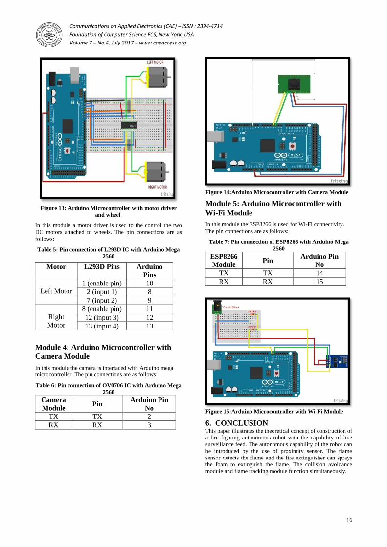
Module 5: Arduino Microcontroller with
Wi-Fi Module
In this module the ESP8266 is used for Wi-Fi connectivity.
The pin connections are as follows:
Table 7: Pin connection of ESP8266 with Arduino Mega
2560
ESP8266
Module Pin
Arduino Pin
No
TX TX 14
RX RX 15
Figure 15:Arduino Microcontroller with Wi-Fi Module
6. CONCLUSION This paper illustrates the theoretical concept of construction of
a fire fighting autonomous robot with the capability of live
surveillance feed. The autonomous capability of the robot can
be introduced by the use of proximity sensor. The flame
sensor detects the flame and the fire extinguisher can sprays
the foam to extinguish the flame. The collision avoidance
module and flame tracking module function simultaneously.
Communications on Applied Electronics (CAE) – ISSN : 2394-4714
Foundation of Computer Science FCS, New York, USA
Volume 7 – No.4, July 2017 – www.caeaccess.org
17
The live surveillance feed is obtained using a wireless camera.
The feed from the camera is provided to an interface on the