Auxetic Metamaterials under Direct Impact Loads in a Structural Health Monitoring Framework by James Ayers, Ben Chamish, Tzi-Kang Chen, Anindya Ghoshal, Chandan Kittur, Michael Coatney, Natasha Bradley, and Tyrone Jones ARL-TR-6306 January 2013 Approved for public release; distribution unlimited.
Transcript
Auxetic Metamaterials under Direct Impact Loads in a
Structural Health Monitoring Framework
by James Ayers, Ben Chamish, Tzi-Kang Chen, Anindya Ghoshal, Chandan
Kittur, Michael Coatney, Natasha Bradley, and Tyrone Jones
ARL-TR-6306 January 2013
Approved for public release; distribution unlimited.
NOTICES
Disclaimers
The findings in this report are not to be construed as an official Department of the Army position
unless so designated by other authorized documents.
Citation of manufacturer’s or trade names does not constitute an official endorsement or
approval of the use thereof.
Destroy this report when it is no longer needed. Do not return it to the originator.
Army Research Laboratory Aberdeen Proving Ground, MD 21005
ARL-TR-6306 January 2013
Auxetic Metamaterials under Direct Impact Loads in a
Structural Health Monitoring Framework
James Ayers, Tzi-Kang Chen, Anindya Ghoshal, Chandan Kittur,
Michael Coatney, and Natasha Bradley Vehicle Technology Directorate, ARL
Ben Chamish and Tyrone Jones Weapons and Materials Research Directorate, ARL
Approved for public release; distribution unlimited.
ii
REPORT DOCUMENTATION PAGE Form Approved OMB No. 0704-0188
Public reporting burden for this collection of information is estimated to average 1 hour per response, including the time for reviewing instructions, searching existing data sources, gathering and maintaining the
data needed, and completing and reviewing the collection information. Send comments regarding this burden estimate or any other aspect of this collection of information, including suggestions for reducing the
burden, to Department of Defense, Washington Headquarters Services, Directorate for Information Operations and Reports (0704-0188), 1215 Jefferson Davis Highway, Suite 1204, Arlington, VA 22202-4302.
Respondents should be aware that notwithstanding any other provision of law, no person shall be subject to any penalty for failing to comply with a collection of information if it does not display a currently valid
OMB control number.
PLEASE DO NOT RETURN YOUR FORM TO THE ABOVE ADDRESS.
1. REPORT DATE (DD-MM-YYYY)
January 2013
2. REPORT TYPE
Final
3. DATES COVERED (From - To)
1 October 2011 to 30 September 2012 4. TITLE AND SUBTITLE
Auxetic Metamaterials under Direct Impact Loads in a Structural Health
Monitoring Framework
5a. CONTRACT NUMBER
5b. GRANT NUMBER
5c. PROGRAM ELEMENT NUMBER
6. AUTHOR(S)
James Ayers, Ben Chamish, Tzi-Kang Chen, Anindya Ghoshal, Chandan Kittur,
Michael Coatney, Natasha Bradley, and Tyrone Jones
5d. PROJECT NUMBER
5e. TASK NUMBER
5f. WORK UNIT NUMBER
7. PERFORMING ORGANIZATION NAME(S) AND ADDRESS(ES)
U.S. Army Research Laboratory
ATTN: RDRL-VTM
Aberdeen Proving Ground, MD 21005
8. PERFORMING ORGANIZATION REPORT NUMBER
ARL-TR-6306
9. SPONSORING/MONITORING AGENCY NAME(S) AND ADDRESS(ES)
10. SPONSOR/MONITOR’S ACRONYM(S)
11. SPONSOR/MONITOR’S REPORT NUMBER(S)
12. DISTRIBUTION/AVAILABILITY STATEMENT
Approved for public release; distribution unlimited.
13. SUPPLEMENTARY NOTES
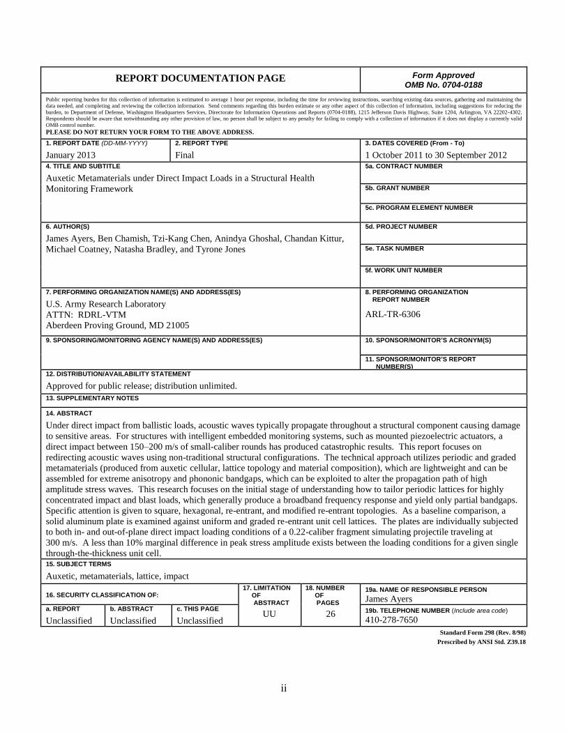
14. ABSTRACT
Under direct impact from ballistic loads, acoustic waves typically propagate throughout a structural component causing damage
to sensitive areas. For structures with intelligent embedded monitoring systems, such as mounted piezoelectric actuators, a
direct impact between 150–200 m/s of small-caliber rounds has produced catastrophic results. This report focuses on
redirecting acoustic waves using non-traditional structural configurations. The technical approach utilizes periodic and graded
metamaterials (produced from auxetic cellular, lattice topology and material composition), which are lightweight and can be
assembled for extreme anisotropy and phononic bandgaps, which can be exploited to alter the propagation path of high
amplitude stress waves. This research focuses on the initial stage of understanding how to tailor periodic lattices for highly
concentrated impact and blast loads, which generally produce a broadband frequency response and yield only partial bandgaps.
Specific attention is given to square, hexagonal, re-entrant, and modified re-entrant topologies. As a baseline comparison, a
solid aluminum plate is examined against uniform and graded re-entrant unit cell lattices. The plates are individually subjected
to both in- and out-of-plane direct impact loading conditions of a 0.22-caliber fragment simulating projectile traveling at
300 m/s. A less than 10% marginal difference in peak stress amplitude exists between the loading conditions for a given single
through-the-thickness unit cell. 15. SUBJECT TERMS
Auxetic, metamaterials, lattice, impact
16. SECURITY CLASSIFICATION OF: 17. LIMITATION OF ABSTRACT
Figure 1. Notional embedded structural health monitoring system for impact. .............................1
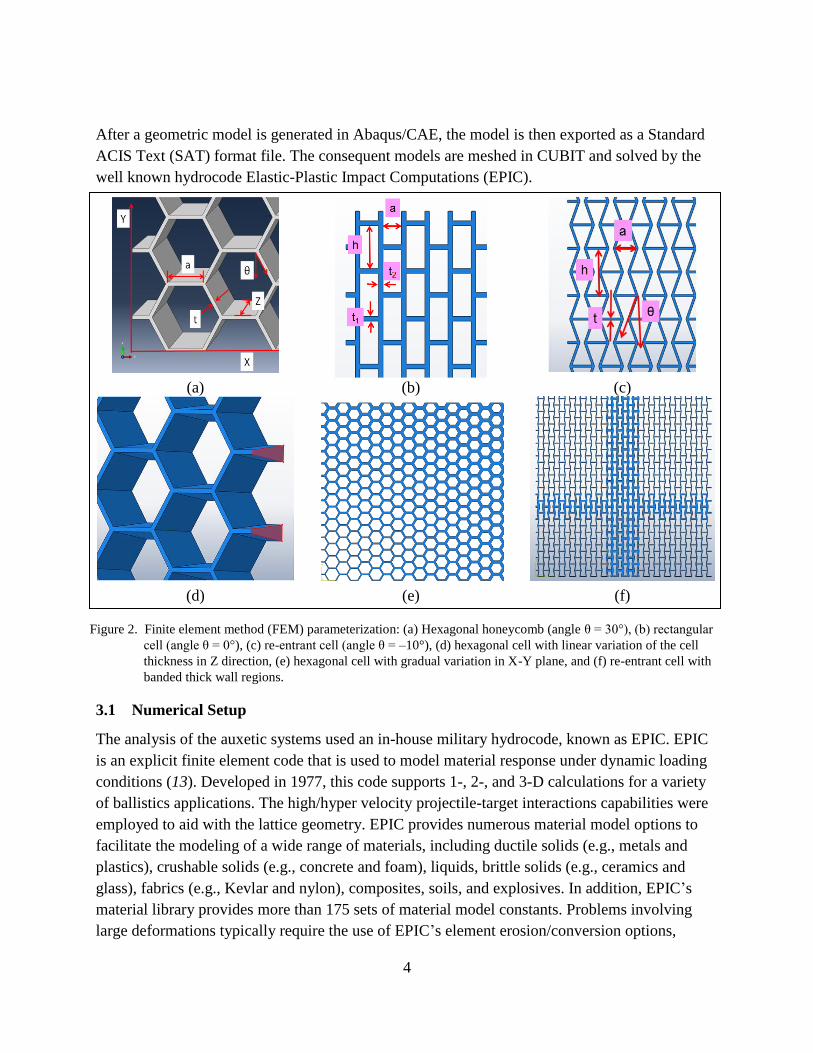
Figure 2. Finite element method (FEM) parameterization: (a) Hexagonal honeycomb (angle θ = 30°), (b) rectangular cell (angle θ = 0°), (c) re-entrant cell (angle θ = –10°), (d) hexagonal cell with linear variation of the cell thickness in Z direction, (e) hexagonal cell with gradual variation in X-Y plane, and (f) re-entrant cell with banded thick wall regions. .......................................................................................................................................4
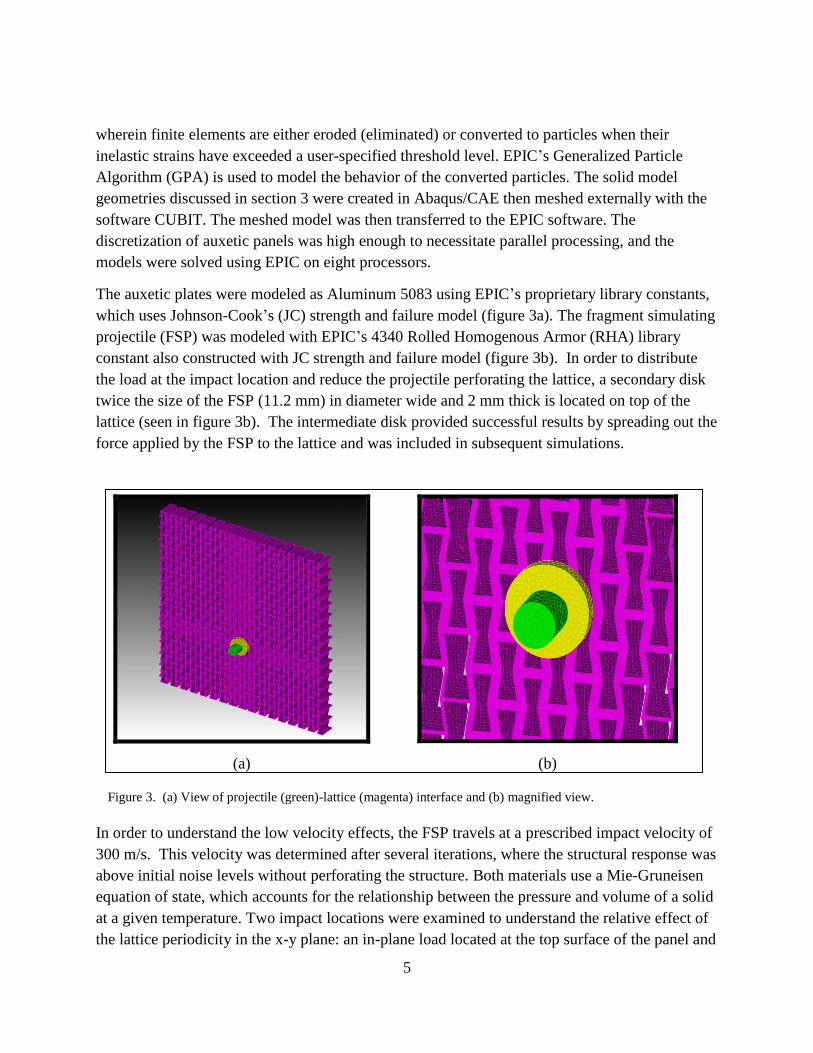
Figure 3. (a) View of projectile (green)-lattice (magenta) interface and (b) magnified view. .......5
Figure 4. Loading conditions: (a) in-plane impact and (b) out of plane impact of the FSP impacting the periodic lattice. ....................................................................................................6
Figure 5. Loading profile: (a) time domain and (b) frequency content. .........................................6
Figure 6. Comparison of time history of wave propagation for in-plane loading: (a) solid plate, (b) uniform auxetic lattice, and (c) graded T-banded auxetic lattice. ..............................8
Figure 7. Comparison of time history of wave propagation for out-of-plane loading: (a) solid plate, (b) uniform auxetic lattice, and (c) graded T-banded auxetic lattice. ..........................10
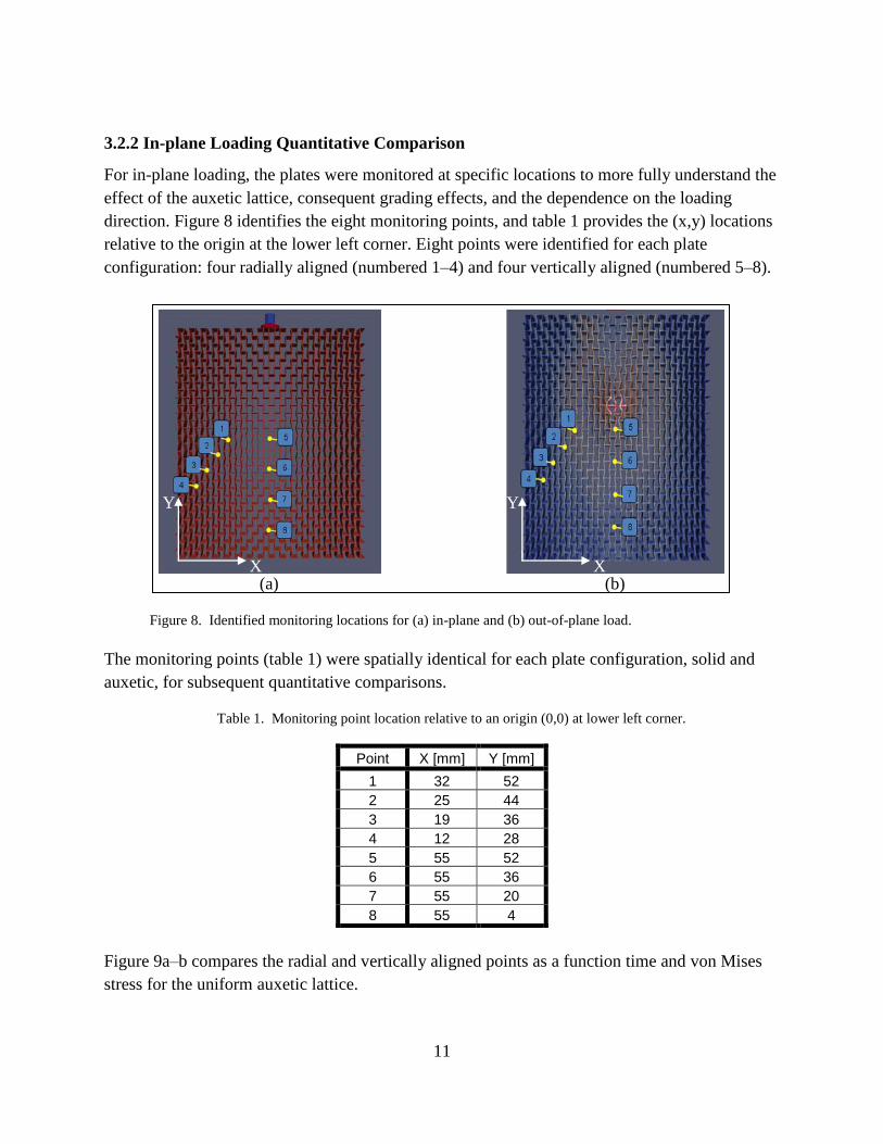
Figure 8. Identified monitoring locations for (a) in-plane and (b) out-of-plane load. ..................11
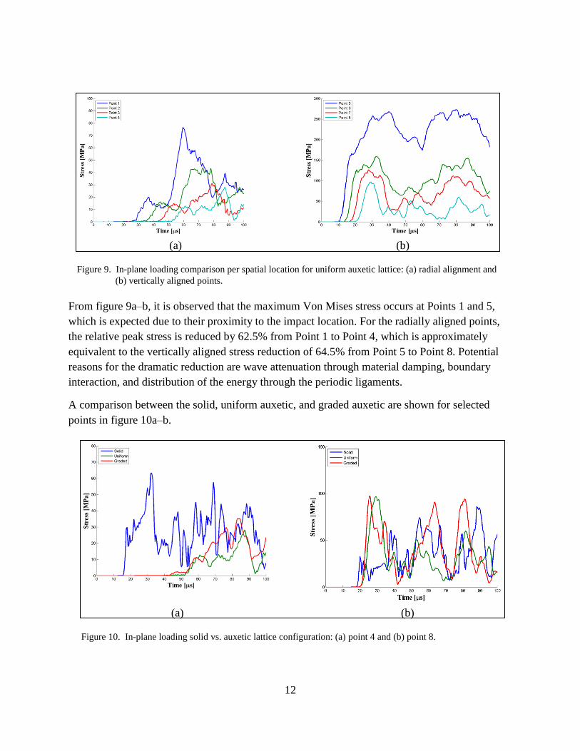
Figure 9. In-plane loading comparison per spatial location for uniform auxetic lattice: (a) radial alignment and (b) vertically aligned points. .............................................................12
Figure 10. In-plane loading solid versus auxetic lattice configuration: (a) point 4 and (b) point 8. ................................................................................................................................12
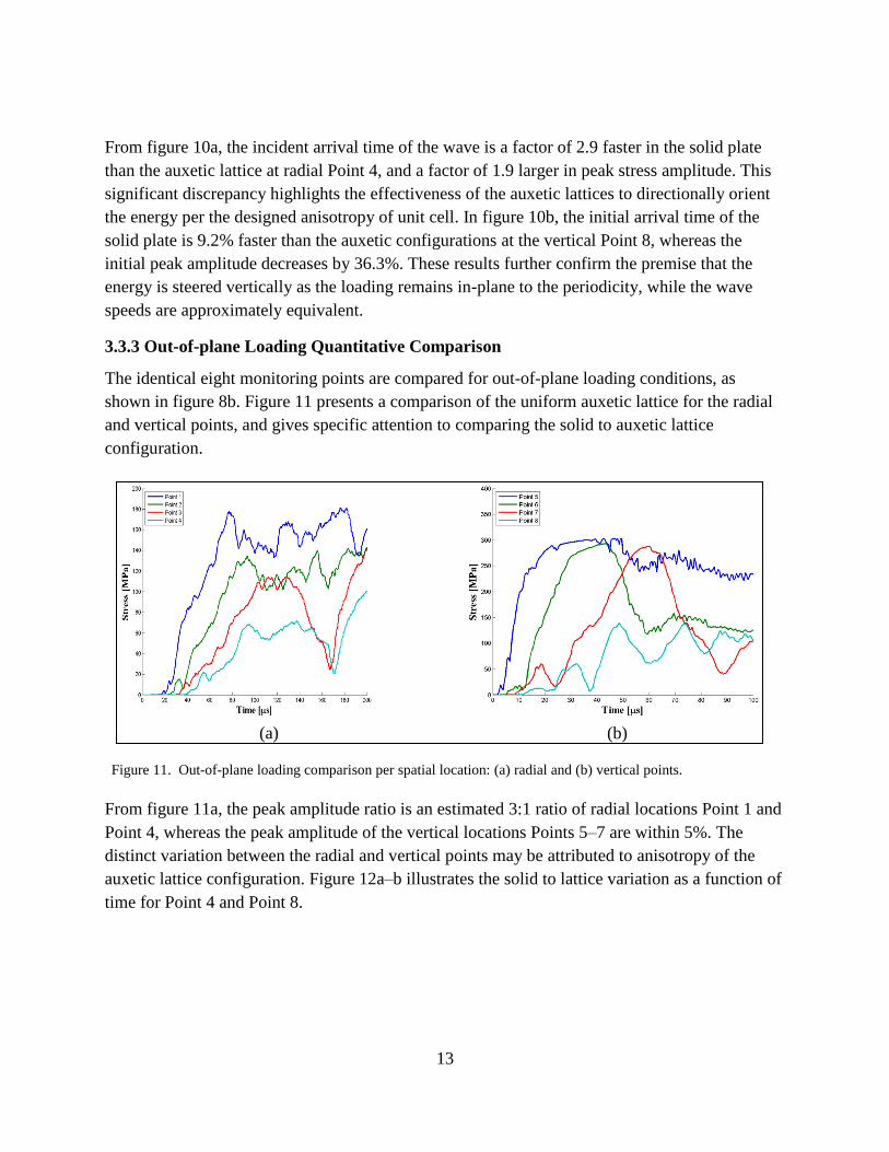
Figure 11. Out-of-plane loading comparison per spatial location: (a) radial and (b) vertical points. .......................................................................................................................................13
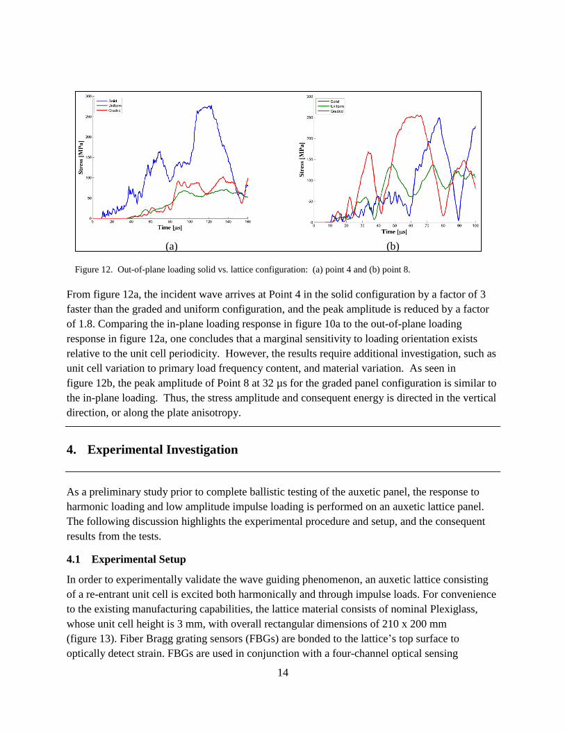
Figure 12. Out-of-plane loading solid vs. lattice configuration: (a) point 4 and (b) point 8. ......14
Figure 13. Auxetic panel: (a) schematic and (b) plexiglass panel with bonded piezoelectric actuator. ....................................................................................................................................15
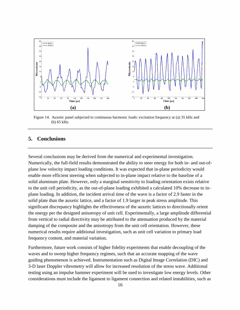
Figure 14. Auxetic panel subjected to continuous harmonic loads: excitation frequency at (a) 35 kHz and (b) 65 kHz. .....................................................................................................16
List of Tables
Table 1. Monitoring point location relative to an origin (0,0) at lower left corner. .....................11
1
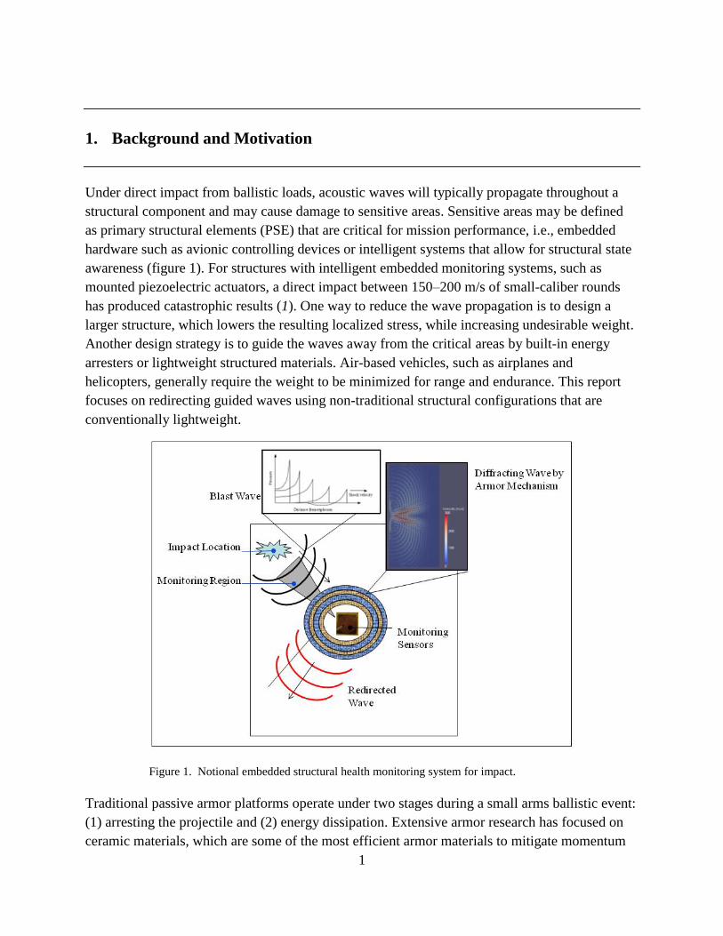
1. Background and Motivation
Under direct impact from ballistic loads, acoustic waves will typically propagate throughout a
structural component and may cause damage to sensitive areas. Sensitive areas may be defined
as primary structural elements (PSE) that are critical for mission performance, i.e., embedded
hardware such as avionic controlling devices or intelligent systems that allow for structural state
awareness (figure 1). For structures with intelligent embedded monitoring systems, such as
mounted piezoelectric actuators, a direct impact between 150–200 m/s of small-caliber rounds
has produced catastrophic results (1). One way to reduce the wave propagation is to design a
larger structure, which lowers the resulting localized stress, while increasing undesirable weight.
Another design strategy is to guide the waves away from the critical areas by built-in energy
arresters or lightweight structured materials. Air-based vehicles, such as airplanes and
helicopters, generally require the weight to be minimized for range and endurance. This report
focuses on redirecting guided waves using non-traditional structural configurations that are
conventionally lightweight.
Figure 1. Notional embedded structural health monitoring system for impact.
Traditional passive armor platforms operate under two stages during a small arms ballistic event:
(1) arresting the projectile and (2) energy dissipation. Extensive armor research has focused on
ceramic materials, which are some of the most efficient armor materials to mitigate momentum
2
transfer of a small- or medium-caliber projectile (2). Ceramic recipes rely on stiffness from
backing materials to work on arresting the projectile. These backing materials are usually bonded
behind ceramics with low-density, low-impedance, and low shear strength adhesives. The
backing is largely used to dissipate the kinetic energy in a ceramic armor system. As an example,
experimental and modeling methods have been developed to investigate mechanical responses
on sandwich composite panels subjected to the impact of explosively driven wet sand (3). Under
high-intensity dynamic loading, sandwich panels suffered 30% less deflection than equivalent
solid plates. One-dimensional studies were used to study the momentum and energy transfer to
plates in air blasts (4).
Other work investigated the dynamic behavior of two types of sandwich composites composed
of E-Glass Vinyl-Ester (EVE) face sheets and Corecell™ A-series foam with a polyurea
interlayer (5). Using a shock tube apparatus to subject samples to high-intensity impulse loading,
results show that the addition of polyurea interlayer improves the overall blast performance and
maintains structural integrity. However, ceramic armor concepts can suffer due to parasitic
weight. One method of reducing the energy is by redirecting a significant portion of the energy,
i.e., shock waves, as the projectile impacts the armor, which improves the ballistic performance
of passive armor systems (6). It is expected that the understanding and development of novel
dynamic energy dissipation mechanisms for armor systems under high ballistic loading rates will
forge the development of new and possibly improved solutions for protection (7).
Metamaterial research is an emerging area due to recent advances in additive manufacturing and
has been broadly defined as materials that have properties associated with the structure as
opposed to their inherent chemical composition. One researched metamaterial is a periodic
lattice, which has the distinct structural advantage of redundancy for load paths and contact
interface. One such periodic lattice is the auxetic configuration, which is characterized by a
negative Poisson’s ratio, where the lattice exhibits a dilatation under tensile loads and contraction
under compressive loads. Continuous periodic structures with a cell structure smaller than a
desired wavelength will attenuate and guide waves (8). Unit cells with negative internal angles
have shown to reduce the angular range of wave propagation (9). In addition, auxetic topologies
with angles between –30° and 30° have shown to propagate waves primarily in the vertical
direction. The negative internal angle has the added benefit of having significantly less
propagation in the horizontal direction. There is also a change in the directionality depending on
the frequency of the excitation.
Other work focused on in-plane wave propagation in chiral lattices using Bloch analysis, with
sets of parameters that affect the elasto-dynamic behavior, suggesting a class of lattice for
designing novel photonic metamaterials (10). Periodicity has been exploited with resistive
inductive (RL) shunted piezoelectric patches to control vibrations of a cantilever aluminum plate
(11). Results indicate that the unit cell approach can predict the actual response of the system.
3
The auxetic lattice also exhibits anisotropy, which means a dependence on direction. Since the
acoustic waves must follow a path along the structure, the energy is diverted in the path of least
resistance. Functionally graded materials (FGMs) have been modeled to investigate propagation
of large amplitude waves within layered and graded structures. Results illustrate that it involves
complex coupling of elastic and viscoelastic responses (12).
2. Objectives and Technical Approach
The primary objective of this research is to understand how waves propagate in inorganic
materials under direct impact loads. A secondary goal is to develop optimized structures that
distribute energy and stress levels to specified locations. The approach is to utilize the
anisotropic behavior of auxetic periodic lattices to redirect the energy, and then to fabricate and
test the metamaterials under prescribed loading conditions that are parallel and perpendicular to
the periodicity of the lattice. The developed configurations are evaluated against a baseline
configuration, which is a simplified metallic plate.
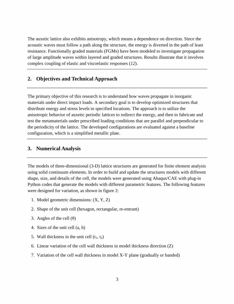
3. Numerical Analysis
The models of three-dimensional (3-D) lattice structures are generated for finite element analysis
using solid continuum elements. In order to build and update the structures models with different
shape, size, and details of the cell, the models were generated using Abaqus/CAE with plug-in
Python codes that generate the models with different parametric features. The following features
were designed for variation, as shown in figure 2:
1. Model geometric dimensions: (X, Y, Z)
2. Shape of the unit cell (hexagon, rectangular, re-entrant)
3. Angles of the cell (θ)
4. Sizes of the unit cell (a, h)
5. Wall thickness in the unit cell (t1, t2)
6. Linear variation of the cell wall thickness in model thickness direction (Z)
7. Variation of the cell wall thickness in model X-Y plane (gradually or banded)
4
After a geometric model is generated in Abaqus/CAE, the model is then exported as a Standard
ACIS Text (SAT) format file. The consequent models are meshed in CUBIT and solved by the
well known hydrocode Elastic-Plastic Impact Computations (EPIC).