Please initial and route to the following for information before filing X Service Manager X Warranty X Service Technicians - Initial Below X Service Advisor Parts Mgr. X Service Advisor Body Shop X Shop Foreman PDI Dept. « « FIX IT RIGHT THE FIRST TIME, ON TIME, EVERY TIME « « 2002 BMW of North America, LLC by: Installation Instructions Page 1 of 19 9/17/02 Lights M63 01 02 Product Development SUBJECT Auxiliary Driving Light Installation Kit P/N 63 12 0 144 132 MODEL MINI Cooper as of 1/02 Mini Cooper S as of 3/02 IMPORTANT: For cars with a combination of Xenon Light (SA 522) and High Pressure Washing System (SA 502), a different/reinforced hood damper (P/N 51 23 7 064 485), must be installed for safety reasons. Customers should check State and Local laws regarding proper operation and use of Auxiliary Driving Lamps. For example, many States prohibit more than four headlamps illuminated at the same time; other States prohibit any on-road use and require the lamps to be covered with the Auxiliary Driving Light caps when not in use. Auxiliary driving lamps enhance the "high beam" visibility provided by dual, quad and six- headlamp systems and are not a fog light or a substitute for normal headlights. Therefore these lights will only be operational in conjunction with the high beam lights. Never use the Auxiliary Driving Lights with the covers/caps attached. This may cause damage to the Auxiliary Driving Lights as well as to the covers/caps.
Transcript
Please initial and route to the following for information before filing
X Service Manager X Warranty X Service Technicians - Initial Below
X Service Advisor Parts Mgr.
X Service Advisor Body Shop
X Shop Foreman PDI Dept.
« « FIX IT RIGHT THE FIRST TIME, ON TIME, EVERY TIME « «
2002 BMW of North America, LLC by:
Installation Instructions Page 1 of 19
9/17/02
Lights M63 01 02 Product Development
SUBJECT Auxiliary Driving Light Installation Kit P/N 63 12 0 144 132 MODEL MINI Cooper as of 1/02 Mini Cooper S as of 3/02
IMPORTANT: For cars with a combination of Xenon Light (SA 522) and High Pressure Washing System (SA 502), a different/reinforced hood damper (P/N 51 23 7 064 485), must be installed for safety reasons. Customers should check State and Local laws regarding proper operation and use of Auxiliary Driving Lamps. For example, many States prohibit more than four headlamps illuminated at the same time; other States prohibit any on-road use and require the lamps to be covered with the Auxiliary Driving Light caps when not in use. Auxiliary driving lamps enhance the "high beam" visibility provided by dual, quad and six-headlamp systems and are not a fog light or a substitute for normal headlights. Therefore these lights will only be operational in conjunction with the high beam lights. Never use the Auxiliary Driving Lights with the covers/caps attached. This may cause damage to the Auxiliary Driving Lights as well as to the covers/caps.
2
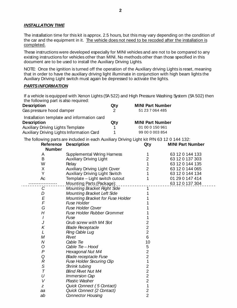
INSTALLATION TIME The installation time for this kit is approx. 2.5 hours, but this may vary depending on the condition of the car and the equipment in it. The vehicle does not need to be recoded after the installation is completed.
These instructions were developed especially for MINI vehicles and are not to be compared to any existing instructions for vehicles other than MINI. No methods other than those specified in this document are to be used to install the Auxiliary Driving Lights.
NOTE: Once the ignition is turned off the operation of the Auxiliary driving Lights is reset, meaning that in order to have the auxiliary driving light illuminate in conjunction with high beam lights the Auxiliary Driving Light switch must again be depressed to activate the lights.
PARTS INFORMATION If a vehicle is equipped with Xenon Lights (SA 522) and High Pressure Washing System (SA 502) then the following part is also required:
Description Qty MINI Part Number Gas pressure hood damper 2 51 23 7 064 485
Installation template and information card Description Qty MINI Part Number Auxiliary Driving Lights Template 1 01 00 0 150 961 Auxiliary Driving Lights Information Card 1 99 00 0 003 854
The following parts are included in each Auxiliary Driving Light kit P/N 63 12 0 144 132: Reference
Number Description Qty MINI Part Number
A Supplemental Wiring Harness 1 63 12 0 144 133 B Auxiliary Driving Light 2 63 12 0 137 303 W Relay 1 63 12 0 144 135 X Auxiliary Driving Light Cover 2 63 12 0 144 065 Y Auxiliary Driving Light Switch 1 63 12 0 144 134
C Mounting Bracket Right Side 1 D Mounting Bracket Left Side 1 E Mounting Bracket for Fuse Holder 1 F Fuse Holder 1 G Fuse Holder Cover 1 H Fuse Holder Rubber Grommet 1 I Fuse 1 J Grub screw with M4 Slot 2 K Blade Receptacle 2 L Ring Cable Lug 2 M Rivet 6 N Cable Tie 10 O Cable Tie – Hood 5 P Hexagonal Nut M4 2 Q Blade receptacle Fuse 2 R Fuse Holder Securing Clip 1 S Shrink tubing 2 T Blind Rivet Nut M4 2 U Immersion Cap 2 V Plastic Washer 2 z Quick Connect ( 5 Contact) 1
aa Quick Connect (2 Contact) 2 ab Connector Housing 2
3
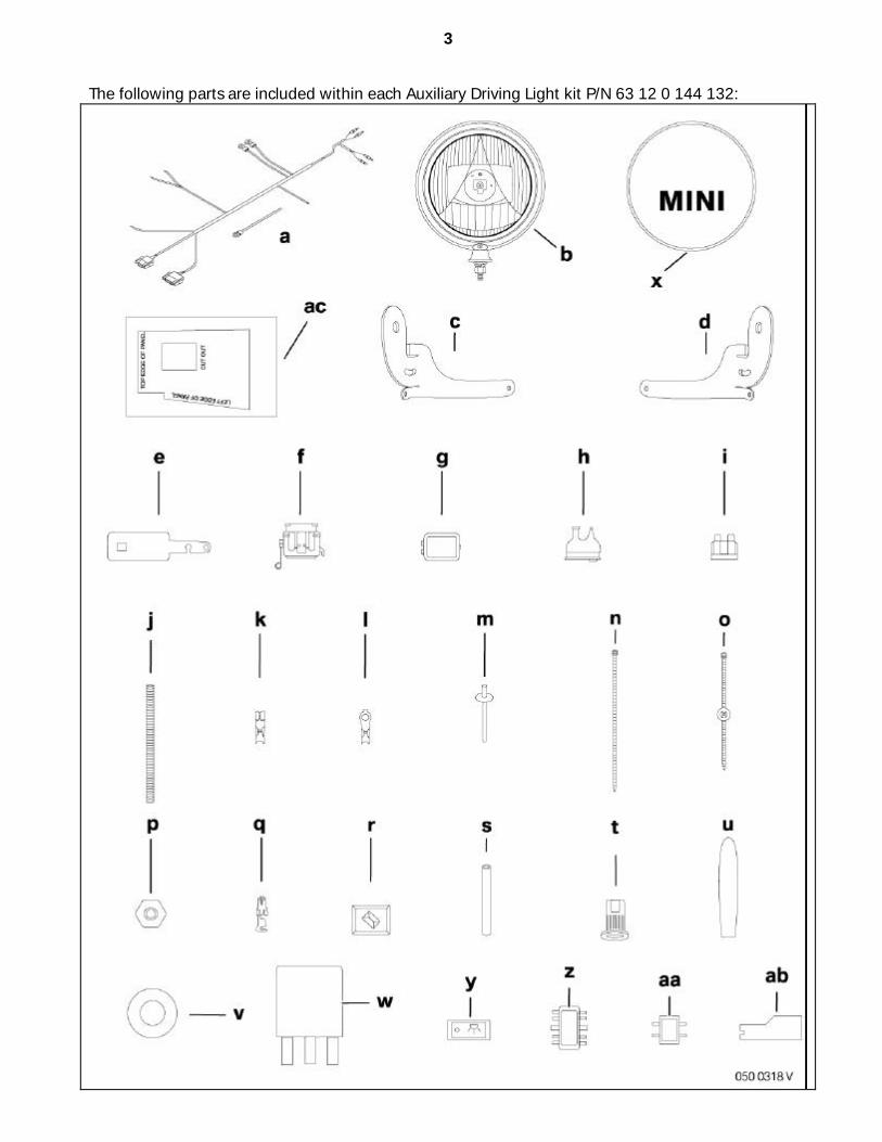
The following parts are included within each Auxiliary Driving Light kit P/N 63 12 0 144 132:
4
PROCEDURE: A. Installation and Routing Diagram for Supplemental Harness
1. Auxiliary Driving Light
2. Fuse box
3. Main Fuse box (vehicle)
4. Auxiliary Driving Light Switch
5. Cable route inside the car
6. Body Control Module (BC1)
7. Relay
8. Ground bolt
9. Main plug of radio
10. Grommet
B. Supplemental Wiring Harness Connection Overview
Item Description Color Connection location A Supplemental Wiring Harness B 2 Open Wires RT
BR Right Auxiliary Driving Light
C 2 Open Wires RT BR
Left Auxiliary Driving Light
D Ring Cable Lug BR Ground Bolt E Ring Cable Lug BR Ground Bolt F 2 Open Wires GR/RT
VI/BL Connection to Radio via “Quick Connect”
G Open Wire GE/GN Body Control Module (BC1) X322 Pin 15 H Relay Base Socket Driver’s Footwell I Light Switch Connector Auxiliary Driving Light Switch - Driver’s
Knee Bolster
J Open Wire RT Fuse Box K Open Contact RT Fuse Box L Ring Cable Lug RT Main Fuse Box
5
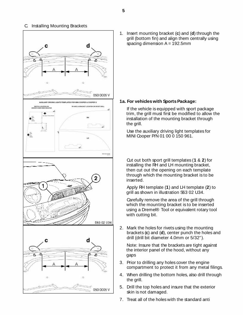
C. Installing Mounting Brackets
1. Insert mounting bracket (c) and (d) through the grill (bottom fin) and align them centrally using spacing dimension A = 192.5mm
1a. For vehicles with Sports Package:
If the vehicle is equipped with sport package trim, the grill must first be modified to allow the installation of the mounting bracket through the grill.
Use the auxiliary driving light templates for MINI Cooper P/N 01 00 0 150 961.
Cut out both sport grill templates (1 & 2) for installing the RH and LH mounting bracket, then cut out the opening on each template through which the mounting bracket is to be inserted.
Apply RH template (1) and LH template (2) to grill as shown in illustration S63 02 U34.
Carefully remove the area of the grill through which the mounting bracket is to be inserted using a Dremel® Tool or equivalent rotary tool with cutting bit.
2. Mark the holes for rivets using the mounting brackets (c) and (d), center punch the holes and drill (drill bit diameter 4.0mm or 5/32”).
Note: Insure that the brackets are tight against the interior panel of the hood, without any gaps
3. Prior to drilling any holes cover the engine compartment to protect it from any metal filings.
4. When drilling the bottom holes, also drill through the grill.
5. Drill the top holes and insure that the exterior skin is not damaged.
7. Treat all of the holes with the standard anti corrosion measures.
6
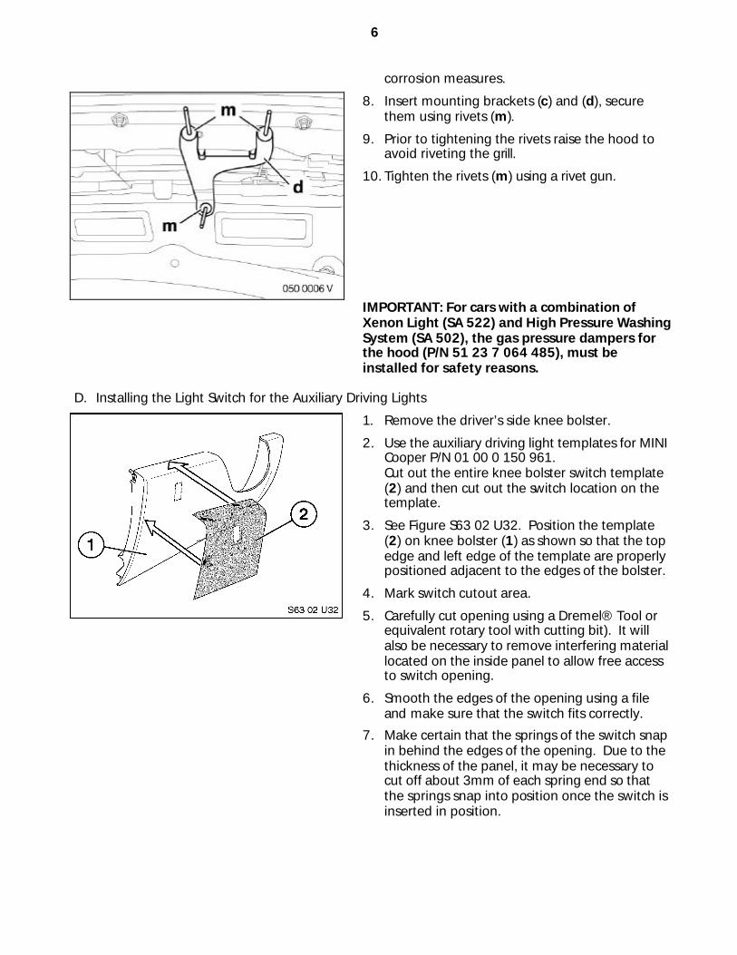
corrosion measures.
8. Insert mounting brackets (c) and (d), secure them using rivets (m).
9. Prior to tightening the rivets raise the hood to avoid riveting the grill.
10. Tighten the rivets (m) using a rivet gun.
IMPORTANT: For cars with a combination of Xenon Light (SA 522) and High Pressure Washing System (SA 502), the gas pressure dampers for the hood (P/N 51 23 7 064 485), must be installed for safety reasons.
D. Installing the Light Switch for the Auxiliary Driving Lights
1. Remove the driver’s side knee bolster.
2. Use the auxiliary driving light templates for MINI Cooper P/N 01 00 0 150 961. Cut out the entire knee bolster switch template (2) and then cut out the switch location on the template.
3. See Figure S63 02 U32. Position the template (2) on knee bolster (1) as shown so that the top edge and left edge of the template are properly positioned adjacent to the edges of the bolster.
4. Mark switch cutout area.
5. Carefully cut opening using a Dremel® Tool or equivalent rotary tool with cutting bit). It will also be necessary to remove interfering material located on the inside panel to allow free access to switch opening.
6. Smooth the edges of the opening using a file and make sure that the switch fits correctly.
7. Make certain that the springs of the switch snap in behind the edges of the opening. Due to the thickness of the panel, it may be necessary to cut off about 3mm of each spring end so that the springs snap into position once the switch is inserted in position.
7
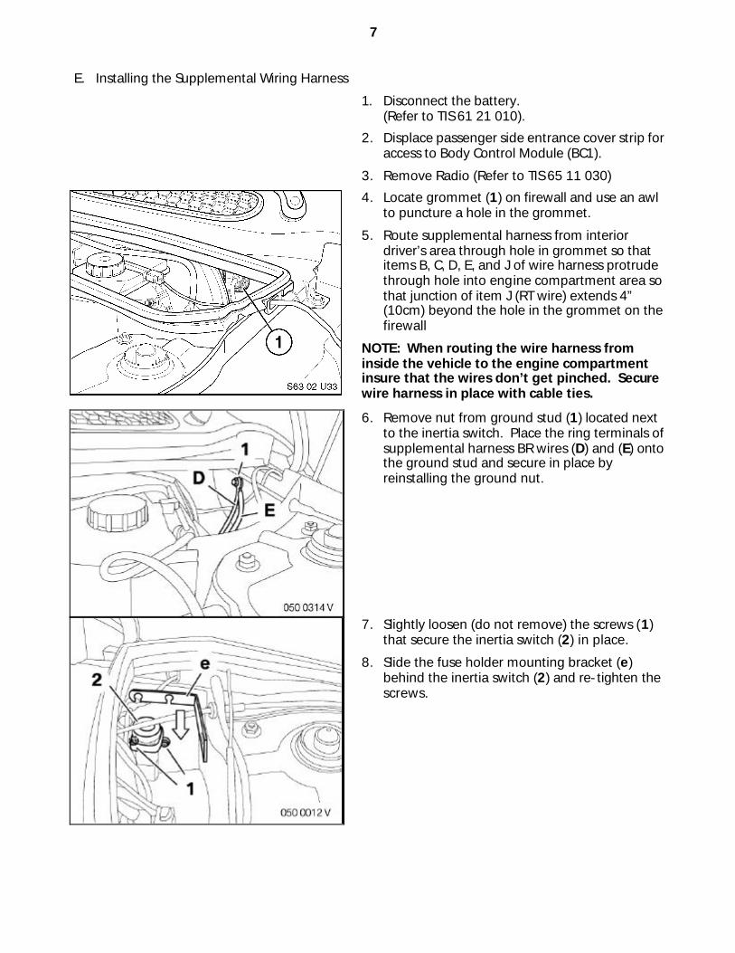
E. Installing the Supplemental Wiring Harness
1. Disconnect the battery. (Refer to TIS 61 21 010).
2. Displace passenger side entrance cover strip for access to Body Control Module (BC1).
3. Remove Radio (Refer to TIS 65 11 030)
4. Locate grommet (1) on firewall and use an awl to puncture a hole in the grommet.
5. Route supplemental harness from interior driver’s area through hole in grommet so that items B, C, D, E, and J of wire harness protrude through hole into engine compartment area so that junction of item J (RT wire) extends 4” (10cm) beyond the hole in the grommet on the firewall
NOTE: When routing the wire harness from inside the vehicle to the engine compartment insure that the wires don’t get pinched. Secure wire harness in place with cable ties.
6. Remove nut from ground stud (1) located next to the inertia switch. Place the ring terminals of supplemental harness BR wires (D) and (E) onto the ground stud and secure in place by reinstalling the ground nut.
7. Slightly loosen (do not remove) the screws (1) that secure the inertia switch (2) in place.
8. Slide the fuse holder mounting bracket (e) behind the inertia switch (2) and re-tighten the screws.
8
9. Route branches (B) and (C) through rubber seal opening (1) and along hood hinge (2). Insert push fasteners with cable ties (O) in vacant holes along hood hinge. Make sure that a portion of the harness with the fabric sleeve is inserted in the wing area of the hood, in a loop shape before securing harness in place with cable ties.
10. Route branches (B) and (C) through the longitudinal opening (1) in the respective mounting bracket (c) and (d) and secure in place using cable ties (n).
IMPORTANT: For cars with a combination of Xenon Lights (SA 522) and High Pressure Washing System (SA 502), a different reinforced hood damper (P/N 51 23 7 064 485) must be installed for safety reasons.
11. Drill a 6mm diameter hole (2) in the plastic trim (3), level with the B+ connector (1) in the main fuse box.
12. Connect ring cable lug (L) from the 20” (50cm) long heavy gauge RT wire to the B+ connector (1) of the main fuse box. Feed the other end of the heavy gauge RT wire through the hole (2) in the plastic trim (3) and route it to the inertia switch area.
13. Use a Dremel® or equivalent rotary tool with a grinding bit to place a grove (4) in plastic cover (5) of the main fuse box.
14. Cut the fuse holder rubber grommet (h) and run the two RT wires (J) and (K) through the grommet (h).
15. Strip the ends of the two RT wires (J) and (K) and crimp on the blade connectors (q).
Note: The blade receptacles (q) are different sizes and must be placed onto the appropriate sized wire.
9
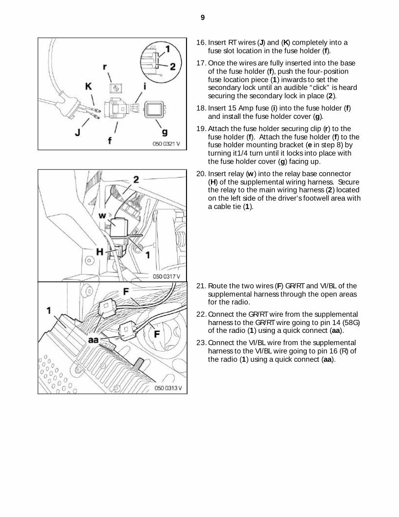
16. Insert RT wires (J) and (K) completely into a fuse slot location in the fuse holder (f).
17. Once the wires are fully inserted into the base of the fuse holder (f), push the four-position fuse location piece (1) inwards to set the secondary lock until an audible “click” is heard securing the secondary lock in place (2).
18. Insert 15 Amp fuse (i) into the fuse holder (f) and install the fuse holder cover (g).
19. Attach the fuse holder securing clip (r) to the fuse holder (f). Attach the fuse holder (f) to the fuse holder mounting bracket (e in step 8) by turning it1/4 turn until it locks into place with the fuse holder cover (g) facing up.
20. Insert relay (w) into the relay base connector (H) of the supplemental wiring harness. Secure the relay to the main wiring harness (2) located on the left side of the driver’s footwell area with a cable tie (1).
21. Route the two wires (F) GR/RT and VI/BL of the supplemental harness through the open areas for the radio.
22. Connect the GR/RT wire from the supplemental harness to the GR/RT wire going to pin 14 (58G) of the radio (1) using a quick connect (aa).
23. Connect the VI/BL wire from the supplemental harness to the VI/BL wire going to pin 16 (R) of the radio (1) using a quick connect (aa).
10
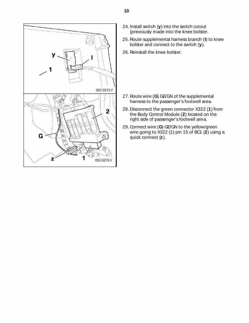
24. Install switch (y) into the switch cutout (previously made into the knee bolster.
25. Route supplemental harness branch (I) to knee bolster and connect to the switch (y).
26. Reinstall the knee bolster.
27. Route wire (G) GE/GN of the supplemental harness to the passenger’s footwell area.
28. Disconnect the green connector X322 (1) from the Body Control Module (2) located on the right side of passenger’s footwell area.
29. Connect wire (G) GE/GN to the yellow/green wire going to X322 (1) pin 15 of BC1 (2) using a quick connect (z).
11
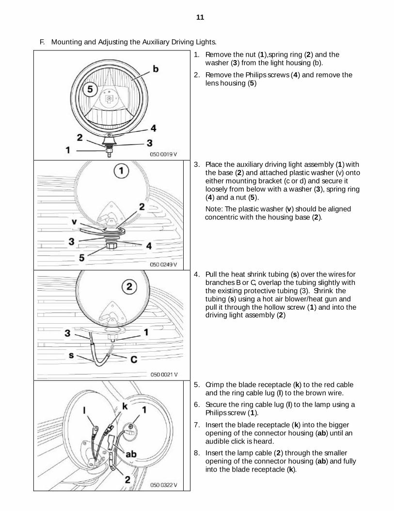
F. Mounting and Adjusting the Auxiliary Driving Lights.
1. Remove the nut (1),spring ring (2) and the washer (3) from the light housing (b).
2. Remove the Philips screws (4) and remove the lens housing (5)
3. Place the auxiliary driving light assembly (1) with the base (2) and attached plastic washer (v) onto either mounting bracket (c or d) and secure it loosely from below with a washer (3), spring ring (4) and a nut (5).
Note: The plastic washer (v) should be aligned concentric with the housing base (2).
4. Pull the heat shrink tubing (s) over the wires for branches B or C, overlap the tubing slightly with the existing protective tubing (3). Shrink the tubing (s) using a hot air blower/heat gun and pull it through the hollow screw (1) and into the driving light assembly (2)
5. Crimp the blade receptacle (k) to the red cable and the ring cable lug (l) to the brown wire.
6. Secure the ring cable lug (l) to the lamp using a Philips screw (1).
7. Insert the blade receptacle (k) into the bigger opening of the connector housing (ab) until an audible click is heard.
8. Insert the lamp cable (2) through the smaller opening of the connector housing (ab) and fully into the blade receptacle (k).
12
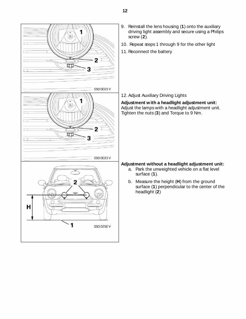
9. Reinstall the lens housing (1) onto the auxiliary driving light assembly and secure using a Philips screw (2).
10. Repeat steps 1 through 9 for the other light
11. Reconnect the battery
12. Adjust Auxiliary Driving Lights
Adjustment with a headlight adjustment unit: Adjust the lamps with a headlight adjustment unit. Tighten the nuts (3) and Torque to 9 Nm.
Adjustment without a headlight adjustment unit: a. Park the unweighted vehicle on a flat level
surface (1).
b. Measure the height (H) from the ground surface (1) perpendicular to the center of the headlight (2)
13
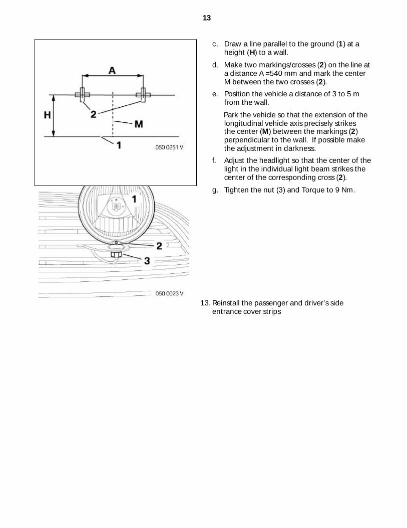
c. Draw a line parallel to the ground (1) at a height (H) to a wall.
d. Make two markings/crosses (2) on the line at a distance A =540 mm and mark the center M between the two crosses (2).
e. Position the vehicle a distance of 3 to 5 m from the wall.
Park the vehicle so that the extension of the longitudinal vehicle axis precisely strikes the center (M) between the markings (2) perpendicular to the wall. If possible make the adjustment in darkness.
f. Adjust the headlight so that the center of the light in the individual light beam strikes the center of the corresponding cross (2).
g. Tighten the nut (3) and Torque to 9 Nm.
13. Reinstall the passenger and driver’s side entrance cover strips
14
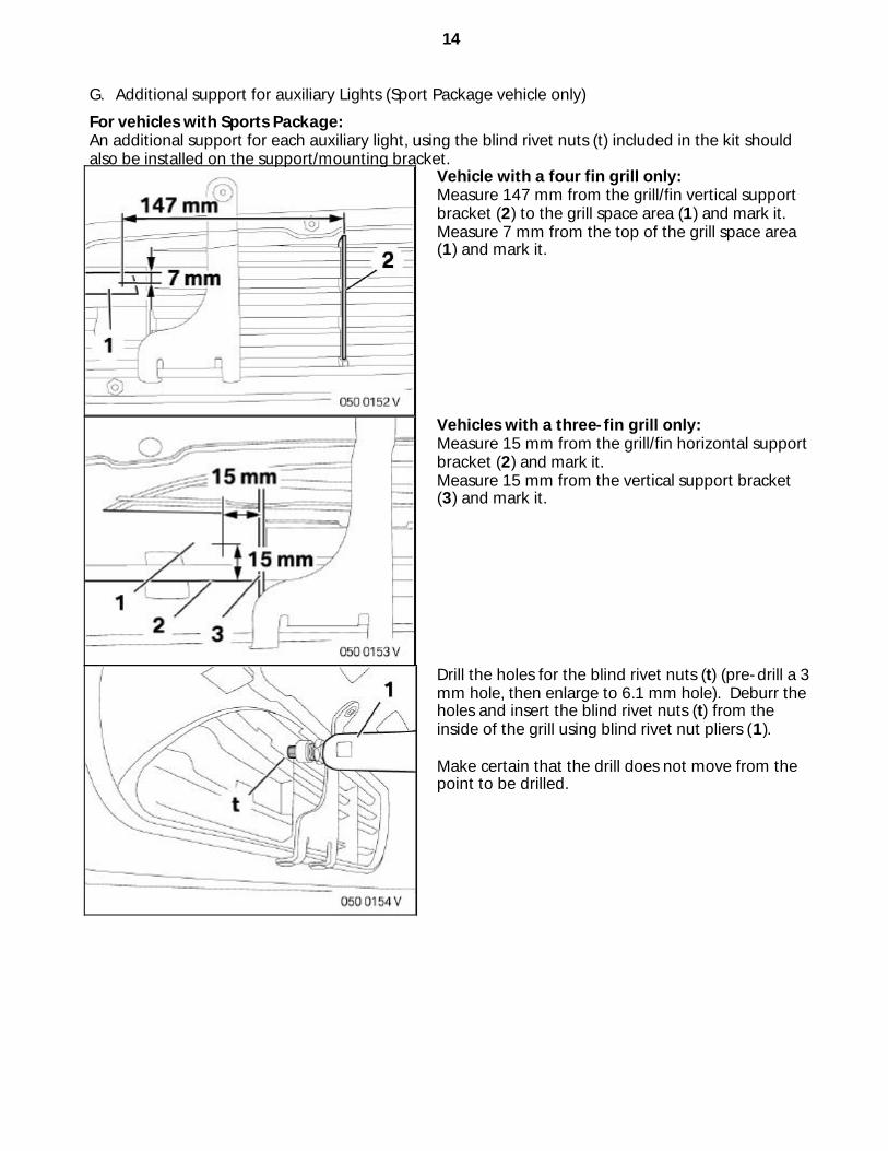
G. Additional support for auxiliary Lights (Sport Package vehicle only)
For vehicles with Sports Package: An additional support for each auxiliary light, using the blind rivet nuts (t) included in the kit should also be installed on the support/mounting bracket.
Vehicle with a four fin grill only: Measure 147 mm from the grill/fin vertical support bracket (2) to the grill space area (1) and mark it. Measure 7 mm from the top of the grill space area (1) and mark it.
Vehicles with a three-fin grill only: Measure 15 mm from the grill/fin horizontal support bracket (2) and mark it. Measure 15 mm from the vertical support bracket (3) and mark it.
Drill the holes for the blind rivet nuts (t) (pre-drill a 3 mm hole, then enlarge to 6.1 mm hole). Deburr the holes and insert the blind rivet nuts (t) from the inside of the grill using blind rivet nut pliers (1). Make certain that the drill does not move from the point to be drilled.
15
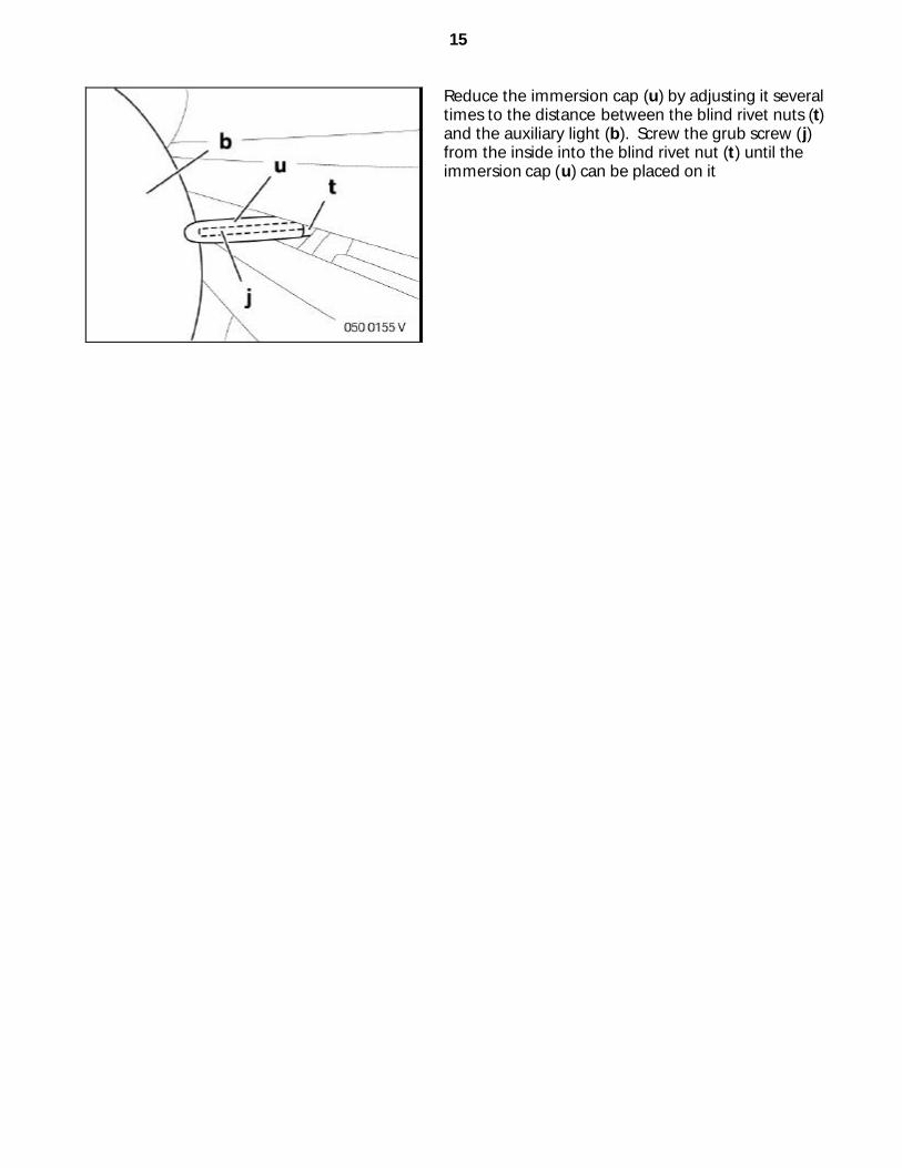
Reduce the immersion cap (u) by adjusting it several times to the distance between the blind rivet nuts (t) and the auxiliary light (b). Screw the grub screw (j) from the inside into the blind rivet nut (t) until the immersion cap (u) can be placed on it
16
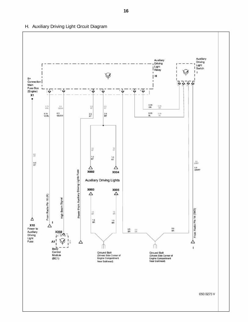
H. Auxiliary Driving Light Circuit Diagram
17
I. Information Sheet for Auxiliary Driving Lights
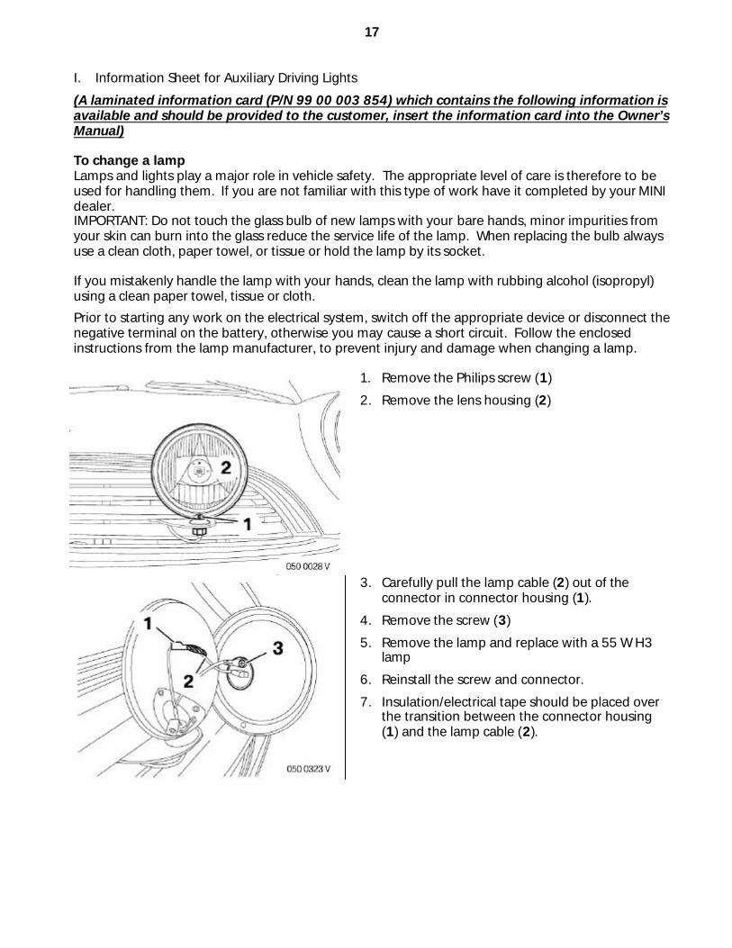
(A laminated information card (P/N 99 00 003 854) which contains the following information is available and should be provided to the customer, insert the information card into the Owner’s Manual) To change a lamp Lamps and lights play a major role in vehicle safety. The appropriate level of care is therefore to be used for handling them. If you are not familiar with this type of work have it completed by your MINI dealer. IMPORTANT: Do not touch the glass bulb of new lamps with your bare hands, minor impurities from your skin can burn into the glass reduce the service life of the lamp. When replacing the bulb always use a clean cloth, paper towel, or tissue or hold the lamp by its socket. If you mistakenly handle the lamp with your hands, clean the lamp with rubbing alcohol (isopropyl) using a clean paper towel, tissue or cloth.
Prior to starting any work on the electrical system, switch off the appropriate device or disconnect the negative terminal on the battery, otherwise you may cause a short circuit. Follow the enclosed instructions from the lamp manufacturer, to prevent injury and damage when changing a lamp.
1. Remove the Philips screw (1)
2. Remove the lens housing (2)
3. Carefully pull the lamp cable (2) out of the connector in connector housing (1).
4. Remove the screw (3)
5. Remove the lamp and replace with a 55 W H3 lamp
6. Reinstall the screw and connector.
7. Insulation/electrical tape should be placed over the transition between the connector housing (1) and the lamp cable (2).
18
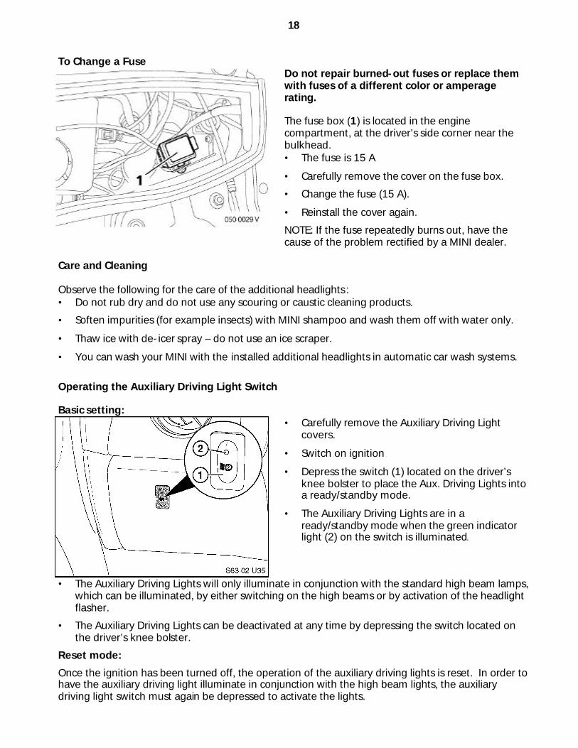
To Change a Fuse
Do not repair burned-out fuses or replace them with fuses of a different color or amperage rating. The fuse box (1) is located in the engine compartment, at the driver’s side corner near the bulkhead. • The fuse is 15 A
• Carefully remove the cover on the fuse box.
• Change the fuse (15 A).
• Reinstall the cover again.
NOTE: If the fuse repeatedly burns out, have the cause of the problem rectified by a MINI dealer.
Care and Cleaning Observe the following for the care of the additional headlights : • Do not rub dry and do not use any scouring or caustic cleaning products.
• Soften impurities (for example insects) with MINI shampoo and wash them off with water only.
• Thaw ice with de-icer spray – do not use an ice scraper.
• You can wash your MINI with the installed additional headlights in automatic car wash systems.
Operating the Auxiliary Driving Light Switch Basic setting:
• Carefully remove the Auxiliary Driving Light covers.
• Switch on ignition
• Depress the switch (1) located on the driver’s knee bolster to place the Aux. Driving Lights into a ready/standby mode.
• The Auxiliary Driving Lights are in a ready/standby mode when the green indicator light (2) on the switch is illuminated.
• The Auxiliary Driving Lights will only illuminate in conjunction with the standard high beam lamps, which can be illuminated, by either switching on the high beams or by activation of the headlight flasher.
• The Auxiliary Driving Lights can be deactivated at any time by depressing the switch located on the driver’s knee bolster.
Reset mode:
Once the ignition has been turned off, the operation of the auxiliary driving lights is reset. In order to have the auxiliary driving light illuminate in conjunction with the high beam lights, the auxiliary driving light switch must again be depressed to activate the lights.
19
IMPORTANT: Customers should check State and Local laws regarding proper operation and use of Auxiliary Driving Lamps. For example, many States prohibit more than four headlamps illuminated at the same time; other States prohibit any on-road use and require the lamps to be covered with the Auxiliary Driving Light caps when not in use. Auxiliary driving lamps enhance the "high beam" visibility provided by dual, quad and six-headlamp systems and are not a fog light or a substitute for normal headlights. Therefore these lights will only be operational in conjunction with the high beam lights. Never use the Auxiliary Driving Lights with the covers/caps attached. This may cause damage to the Auxiliary Driving Lights as well as to the covers/caps.