2 We greatly appreciate your purchase of this unit. 2 To be sure you take maximum advantage of all the features this unit has to offer, read these instructions carefully and use the set properly. Be sure to keep this manual for future reference should any questions or problems arise. “SERIAL NO. PLEASE RECORD UNIT SERIAL NUMBER ATTACHED TO THE REAR OF THE CABINET FOR FUTURE REFERENCE” “NO. DE SERIE PRIERE DE NOTER LE NUMERO DE SERIE DE L’APPAREIL INSCRIT A L’ARRIERE DU COFFRET DE FAÇON A POUVOIR LE CONSULTER EN CAS DE PROBLEME.” 2 Nous vous remercions pour l’achat de cet appareil. 2 Pour être sûr de profiter au maximum de toutes les caractéristiques qu’offre cet appareil, lire avec soin ces instructions et bien utiliser l’appareil. Toujours conserver ce mode d’emploi pour s’y référer ultérieurement en cas de question ou de problème. FOR ENGLISH READERS PAGE 2 ~ PAGE 65, 128 ~ 132 POUR LES LECTEURS FRANCAIS PAGE 2, 66 ~ PAGE 132 AV SURROUND RECEIVER RÉCEPTEUR AUDIO-VIDÉO AVR-1705/685 OPERATING INSTRUCTIONS MODE D’EMPLOI
Transcript
2 We greatly appreciate your purchase of this unit.
2 To be sure you take maximum advantage of all the
features this unit has to offer, read these instructions
carefully and use the set properly. Be sure to keep this
manual for future reference should any questions or
problems arise.
“SERIAL NO.
PLEASE RECORD UNIT SERIAL NUMBER ATTACHED TO
THE REAR OF THE CABINET FOR FUTURE REFERENCE”
“NO. DE SERIE
PRIERE DE NOTER LE NUMERO DE SERIE DE L’APPAREIL
INSCRIT A L’ARRIERE DU COFFRET DE FAÇON A POUVOIR
LE CONSULTER EN CAS DE PROBLEME.”
2 Nous vous remercions pour l’achat de cet appareil.
2 Pour être sûr de profiter au maximum de toutes les
caractéristiques qu’offre cet appareil, lire avec soin ces
instructions et bien utiliser l’appareil. Toujours
conserver ce mode d’emploi pour s’y référer
ultérieurement en cas de question ou de problème.
FOR ENGLISH READERS PAGE 2 ~ PAGE 65, 128 ~ 132 POUR LES LECTEURS FRANCAIS PAGE 2, 66 ~ PAGE 132
AV SURROUND RECEIVERRÉCEPTEUR AUDIO-VIDÉO
AVR-1705/685OPERATING INSTRUCTIONSMODE D’EMPLOI
2
ENGLISH
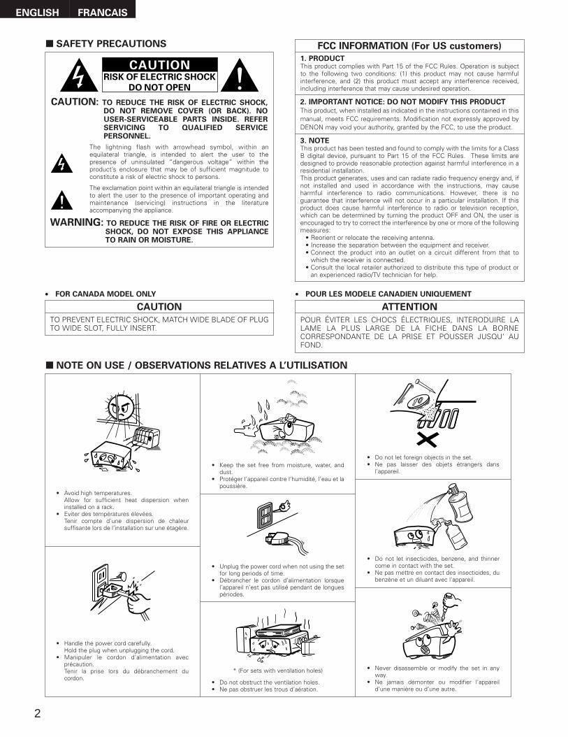
2 SAFETY PRECAUTIONS
2 NOTE ON USE / OBSERVATIONS RELATIVES A L’UTILISATION
• Avoid high temperatures.Allow for sufficient heat dispersion wheninstalled on a rack.
• Eviter des températures élevées. Tenir compte d’une dispersion de chaleursuffisante lors de l’installation sur une étagère.
• Handle the power cord carefully.Hold the plug when unplugging the cord.
• Manipuler le cordon d’alimentation avecprécaution.Tenir la prise lors du débranchement ducordon.
• Keep the set free from moisture, water, anddust.
• Protéger l’appareil contre l’humidité, l’eau et lapoussière.
• Unplug the power cord when not using the setfor long periods of time.
• Débrancher le cordon d’alimentation lorsquel’appareil n’est pas utilisé pendant de longuespériodes.
* (For sets with ventilation holes)
• Do not obstruct the ventilation holes.• Ne pas obstruer les trous d’aération.
• Do not let foreign objects in the set.• Ne pas laisser des objets étrangers dans
l’appareil.
• Do not let insecticides, benzene, and thinnercome in contact with the set.
• Ne pas mettre en contact des insecticides, dubenzène et un diluant avec l’appareil.
• Never disassemble or modify the set in anyway.
• Ne jamais démonter ou modifier l’appareild’une manière ou d’une autre.
CAUTIONRISK OF ELECTRIC SHOCK
DO NOT OPEN
CAUTION: TO REDUCE THE RISK OF ELECTRIC SHOCK,DO NOT REMOVE COVER (OR BACK). NOUSER-SERVICEABLE PARTS INSIDE. REFERSERVICING TO QUALIFIED SERVICEPERSONNEL.
The lightning flash with arrowhead symbol, within anequilateral triangle, is intended to alert the user to thepresence of uninsulated “dangerous voltage” within theproduct’s enclosure that may be of sufficient magnitude toconstitute a risk of electric shock to persons.
The exclamation point within an equilateral triangle is intendedto alert the user to the presence of important operating andmaintenance (servicing) instructions in the literatureaccompanying the appliance.
WARNING: TO REDUCE THE RISK OF FIRE OR ELECTRICSHOCK, DO NOT EXPOSE THIS APPLIANCETO RAIN OR MOISTURE.
CAUTION
TO PREVENT ELECTRIC SHOCK, MATCH WIDE BLADE OF PLUGTO WIDE SLOT, FULLY INSERT.
ATTENTION
POUR ÉVITER LES CHOCS ÉLECTRIQUES, INTERODUIRE LALAME LA PLUS LARGE DE LA FICHE DANS LA BORNECORRESPONDANTE DE LA PRISE ET POUSSER JUSQU’ AUFOND.
FRANCAIS
• FOR CANADA MODEL ONLY • POUR LES MODELE CANADIEN UNIQUEMENT
1. PRODUCTThis product complies with Part 15 of the FCC Rules. Operation is subjectto the following two conditions: (1) this product may not cause harmfulinterference, and (2) this product must accept any interference received,including interference that may cause undesired operation.
2. IMPORTANT NOTICE: DO NOT MODIFY THIS PRODUCT This product, when installed as indicated in the instructions contained in thismanual, meets FCC requirements. Modification not expressly approved byDENON may void your authority, granted by the FCC, to use the product.
3. NOTEThis product has been tested and found to comply with the limits for a ClassB digital device, pursuant to Part 15 of the FCC Rules. These limits aredesigned to provide reasonable protection against harmful interference in aresidential installation.This product generates, uses and can radiate radio frequency energy and, ifnot installed and used in accordance with the instructions, may causeharmful interference to radio communications. However, there is noguarantee that interference will not occur in a particular installation. If thisproduct does cause harmful interference to radio or television reception,which can be determined by turning the product OFF and ON, the user isencouraged to try to correct the interference by one or more of the followingmeasures:
• Reorient or relocate the receiving antenna.• Increase the separation between the equipment and receiver.• Connect the product into an outlet on a circuit different from that to
which the receiver is connected.• Consult the local retailer authorized to distribute this type of product or
an experienced radio/TV technician for help.
FCC INFORMATION (For US customers)
3
SAFETY INSTRUCTIONS1. Read Instructions – All the safety and operating instructions
should be read before the product is operated.2. Retain Instructions – The safety and operating instructions
should be retained for future reference.3. Heed Warnings – All warnings on the product and in the
operating instructions should be adhered to.4. Follow Instructions – All operating and use instructions should
be followed.5. Cleaning – Unplug this product from the wall outlet before
cleaning. Do not use liquid cleaners or aerosol cleaners.6. Attachments – Do not use attachments not recommended by
the product manufacturer as they may cause hazards.7. Water and Moisture – Do not use this product near water – for
example, near a bath tub, wash bowl, kitchen sink, or laundrytub; in a wet basement; or near a swimming pool; and the like.
8. Accessories – Do not place this product on an unstable cart,stand, tripod, bracket, or table. The product may fall, causingserious injury to a child or adult, and serious damage to theproduct. Use only with a cart, stand, tripod, bracket, or tablerecommended by the manufacturer, or sold with the product.Any mounting of the product should follow the manufacturer’sinstructions, and should use a mounting accessory recommended by the manufacturer.
9. A product and cart combination should be moved with care. Quick stops, excessive force, and uneven surfaces may cause the product and cart combination to overturn.
10. Ventilation – Slots and openings in the cabinet are provided forventilation and to ensure reliable operation of the product and toprotect it from overheating, and these openings must not beblocked or covered. The openings should never be blocked byplacing the product on a bed, sofa, rug, or other similar surface.This product should not be placed in a built-in installation suchas a bookcase or rack unless proper ventilation is provided orthe manufacturer’s instructions have been adhered to.
11. Power Sources – This product should be operated only from thetype of power source indicated on the marking label. If you arenot sure of the type of power supply to your home, consult yourproduct dealer or local power company. For products intendedto operate from battery power, or other sources, refer to theoperating instructions.
12. Grounding or Polarization – This product may be equipped witha polarized alternating-current line plug (a plug having one bladewider than the other). This plug will fit into the power outletonly one way. This is a safety feature. If you are unable toinsert the plug fully into the outlet, try reversing the plug. If theplug should still fail to fit, contact your electrician to replace yourobsolete outlet. Do not defeat the safety purpose of thepolarized plug.
13. Power-Cord Protection – Power-supply cords should be routedso that they are not likely to be walked on or pinched by itemsplaced upon or against them, paying particular attention tocords at plugs, convenience receptacles, and the point wherethey exit from the product.
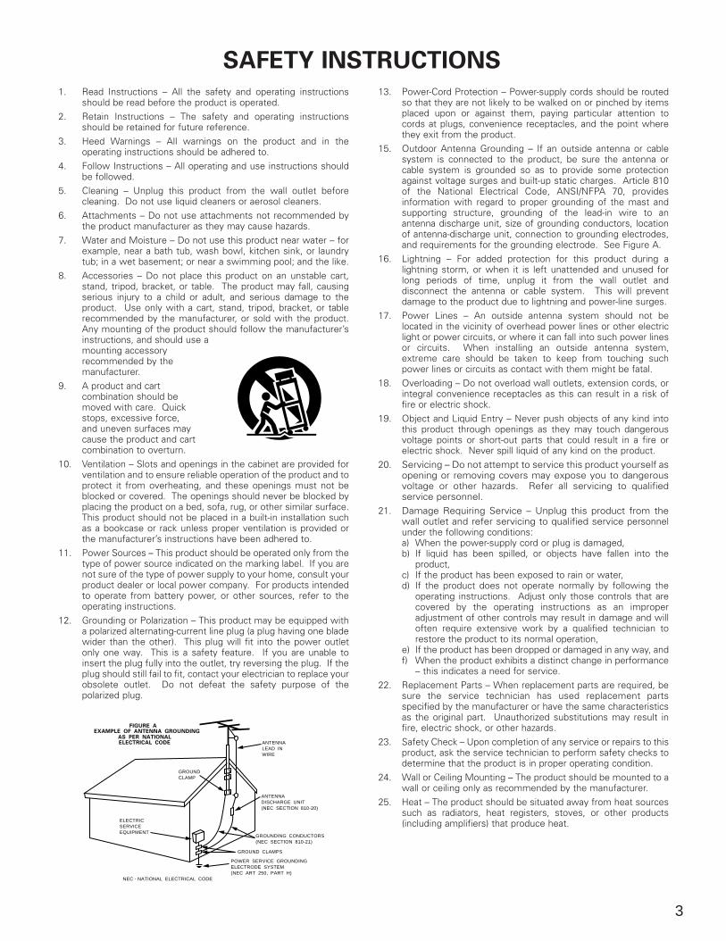
15. Outdoor Antenna Grounding – If an outside antenna or cablesystem is connected to the product, be sure the antenna orcable system is grounded so as to provide some protectionagainst voltage surges and built-up static charges. Article 810of the National Electrical Code, ANSI/NFPA 70, providesinformation with regard to proper grounding of the mast andsupporting structure, grounding of the lead-in wire to anantenna discharge unit, size of grounding conductors, locationof antenna-discharge unit, connection to grounding electrodes,and requirements for the grounding electrode. See Figure A.
16. Lightning – For added protection for this product during alightning storm, or when it is left unattended and unused forlong periods of time, unplug it from the wall outlet anddisconnect the antenna or cable system. This will preventdamage to the product due to lightning and power-line surges.
17. Power Lines – An outside antenna system should not belocated in the vicinity of overhead power lines or other electriclight or power circuits, or where it can fall into such power linesor circuits. When installing an outside antenna system,extreme care should be taken to keep from touching suchpower lines or circuits as contact with them might be fatal.
18. Overloading – Do not overload wall outlets, extension cords, orintegral convenience receptacles as this can result in a risk offire or electric shock.
19. Object and Liquid Entry – Never push objects of any kind intothis product through openings as they may touch dangerousvoltage points or short-out parts that could result in a fire orelectric shock. Never spill liquid of any kind on the product.
20. Servicing – Do not attempt to service this product yourself asopening or removing covers may expose you to dangerousvoltage or other hazards. Refer all servicing to qualifiedservice personnel.
21. Damage Requiring Service – Unplug this product from thewall outlet and refer servicing to qualified service personnelunder the following conditions:a) When the power-supply cord or plug is damaged,b) If liquid has been spilled, or objects have fallen into the
product,c) If the product has been exposed to rain or water,d) If the product does not operate normally by following the
operating instructions. Adjust only those controls that arecovered by the operating instructions as an improperadjustment of other controls may result in damage and willoften require extensive work by a qualified technician torestore the product to its normal operation,
e) If the product has been dropped or damaged in any way, andf) When the product exhibits a distinct change in performance
– this indicates a need for service.22. Replacement Parts – When replacement parts are required, be
sure the service technician has used replacement partsspecified by the manufacturer or have the same characteristicsas the original part. Unauthorized substitutions may result infire, electric shock, or other hazards.
23. Safety Check – Upon completion of any service or repairs to thisproduct, ask the service technician to perform safety checks todetermine that the product is in proper operating condition.
24. Wall or Ceiling Mounting – The product should be mounted to awall or ceiling only as recommended by the manufacturer.
25. Heat – The product should be situated away from heat sourcessuch as radiators, heat registers, stoves, or other products(including amplifiers) that produce heat.
FIGURE AEXAMPLE OF ANTENNA GROUNDING
AS PER NATIONALELECTRICAL CODE ANTENNA
LEAD INWIRE
GROUNDCLAMP
ELECTRICSERVICEEQUIPMENT
ANTENNADISCHARGE UNIT(NEC SECTION 810-20)
GROUNDING CONDUCTORS(NEC SECTION 810-21)
GROUND CLAMPS
POWER SERVICE GROUNDINGELECTRODE SYSTEM(NEC ART 250, PART H)
NEC - NATIONAL ELECTRICAL CODE
4
ENGLISH
2 INTRODUCTION
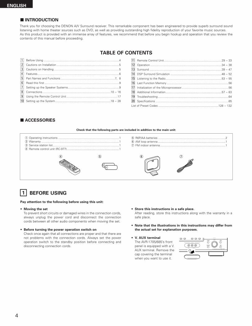
2 ACCESSORIES
Thank you for choosing the DENON A/V Surround receiver. This remarkable component has been engineered to provide superb surround soundlistening with home theater sources such as DVD, as well as providing outstanding high fidelity reproduction of your favorite music sources.As this product is provided with an immense array of features, we recommend that before you begin hookup and operation that you review thecontents of this manual before proceeding.
TABLE OF CONTENTS
Check that the following parts are included in addition to the main unit:
1 BEFORE USING
Pay attention to the following before using this unit:
• Moving the set
To prevent short circuits or damaged wires in the connection cords,always unplug the power cord and disconnect the connectioncords between all other audio components when moving the set.
• Before turning the power operation switch on
Check once again that all connections are proper and that there arenot problems with the connection cords. Always set the poweroperation switch to the standby position before connecting anddisconnecting connection cords.
• Store this instructions in a safe place.
After reading, store this instructions along with the warranty in asafe place.
• Note that the illustrations in this instructions may differ from
the actual set for explanation purposes.
• V. AUX terminal
The AVR-1705/685’s frontpanel is equipped with a V.AUX terminal. Remove thecap covering the terminalwhen you want to use it.
z Before Using ..............................................................................................4
x Cautions on Installation ..............................................................................5
c Cautions on Handling .................................................................................5
v Features......................................................................................................6
b Part Names and Functions....................................................................7, 8
n Read this first .............................................................................................9
m Setting up the Speaker Systems................................................................9
List of Preset Codes ...........................................................................128 ~ 132
q Operating instructions ............................................................................1w Warranty .................................................................................................1e Service station list...................................................................................1r Remote control unit (RC-977) .................................................................1
r t y u
t R6P/AA batteries ....................................................................................2y AM loop antenna ....................................................................................1u FM indoor antenna..................................................................................1
5
ENGLISH
3 CAUTIONS ON HANDLING
• Switching the input function when input jacks are not
connected
A clicking noise may be produced if the input function is switchedwhen nothing is connected to the input jacks. If this happens,either turn down the MASTER VOLUME control or connectcomponents to the input jacks.
• Muting of PRE OUT jack, HEADPHONE jack and SPEAKER
terminals
The PRE OUT jack, HEADPHONE jack and SPEAKER terminalsinclude a muting circuit. Because of this, the output signals aregreatly reduced for several seconds after the power operationswitch is turned on or input function, surround mode or any otherset-up is changed.If the volume is turned up during this time, the output will be veryhigh after the muting circuit stops functioning. Always wait untilthe muting circuit turns off before adjusting the volume.
• Whenever the unit is in the STANDBY state, the apparatus is
still connected on AC line voltage.
Please be sure to turn the power off (£ off) when you leave
home for, say, a vacation.
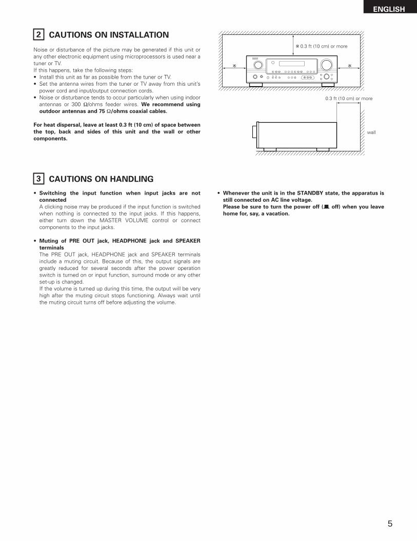
2 CAUTIONS ON INSTALLATION
Noise or disturbance of the picture may be generated if this unit orany other electronic equipment using microprocessors is used near atuner or TV.If this happens, take the following steps:• Install this unit as far as possible from the tuner or TV.• Set the antenna wires from the tuner or TV away from this unit’s
power cord and input/output connection cords.• Noise or disturbance tends to occur particularly when using indoor
antennas or 300 Ω/ohms feeder wires. We recommend using
outdoor antennas and 75 Ω/ohms coaxial cables.
For heat dispersal, leave at least 0.3 ft (10 cm) of space between
the top, back and sides of this unit and the wall or other
components.
0.3 ft (10 cm) or more
wall
0.3 ft (10 cm) or more
6
ENGLISH
4 FEATURES
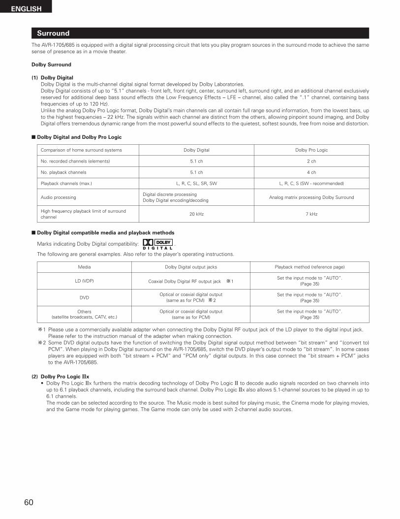
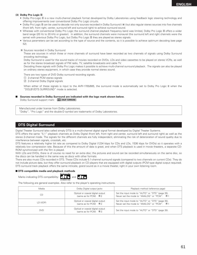
1. Dolby Digital
Using advanced digital processing algorithms, Dolby Digitalprovides up to 5.1 channels of wide-range, high fidelity surroundsound. Dolby Digital is the default digital audio delivery system forDVD and North American DTV.
2. Dolby Pro Logic IIx compatibility
Dolby Pro Logic IIx furthers the matrix decording technology ofDolby Pro Logic II to decode audio signals recorded on twochannels into up to 6.1 playback channels, including the surroundback channel.The mode can be selected according to the source. The Musicmode is best suited for playing music,the Cinema mode forplaying movies, and the Game mode for playing games. TheGame mode can only be used with 2-channel audio sources.
3. Dolby Pro Logic II Game mode compatibility
In addition to the previously offered Music and Cinema modes,the AVR-1705/685 also offers a Game mode optimum for games.
4. DTS (Digital Theater Systems)
DTS provides up to 5.1 channels of wide-range, high fidelitysurround sound, from sources such as laser disc, DVD andspecially-encoded music discs.
5. DTS-ES Extended Surround and DTS Neo:6
The AVR-1705/685 can be decoded with DTS-ES ExtendedSurround, a multi-channel format developed by Digital TheaterSystems Inc.The AVR-1705/685 can be also decoded with DTS Neo:6, asurround mode allowing 6.1 channels playback of regular stereosources.
6. DTS 96/24 compatibility
The AVR-1705/685 can be decoded with sources recorded in DTS96/24, a multi-channel digital signal format developed by DigitalTheater Systems Inc.DTS 96/24 sources can be played in the multi-channel mode onthe AVR-1705/685 with high sound quality of 96 kHz/24 bits or88.2 kHz/24 bits.
7. Video Conversion Function
The AVR-1705/685 is equipped with a function for up-convertingvideo signals.Because of this, the AVR-1705/685’s MONITOR OUT jack can beconnected to the monitor (TV) with a set of cables offering ahigher quality connection, regardless of how the player and theAVR-1705/685’s video input jacks are connected.
8. Component Video Switching
In addition to composite video and “S” video switching, the AVR-1705/685 provides 3 sets of component video (Y, PB/CB, PR/CR)inputs, and one set of component video outputs to the television,for superior picture quality.
9. Auto Surround Mode
This function stores the surround mode last used for an inputsignal in the memory and automatically sets that surround modethe next time that signal is input.
10.Front input terminal
The unit is equipped with a Front Input connector for theconvenient connection of a video camera or other equipment.
11.6CH EXT. IN jacks
This unit is equipped with 6CH EXT. IN jacks for use with audioformats of the future.
12.Personal Memory Plus function
Persinal Memory Plus is an advanced version of PersonalMemory. With Personal Memory Plus, the set automaticallymemorizes the surround mode, channel volume, surroundparameters, etc., for each of the separate input sources.
13.Preset Memory Tuning
56-Station AM/FM Random Preset Memory tuning.
7
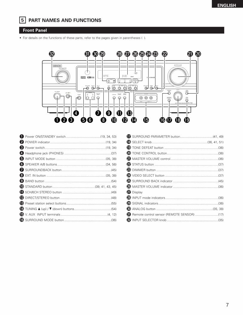
5 PART NAMES AND FUNCTIONS
Front Panel
• For details on the functions of these parts, refer to the pages given in parentheses ( ).
qwu
e ir
yo
!4t!1
@1@2@3@4@5@6@7@8@9
!2!3
!5 !6!7!0 !8
@0
!9
#0#1#2
q Power ON/STANDBY switch.......................................(19, 34, 53)
w POWER indicator...............................................................(19, 34)
e Power switch.....................................................................(19, 34)
r Headphone jack (PHONES) .....................................................(37)
t INPUT MODE button ........................................................(35, 38)
y SPEAKER A/B buttons.......................................................(34, 56)
u SURROUNDBACK button........................................................(45)
i EXT. IN button ...................................................................(35, 38)
o BAND button ...........................................................................(54)
!0 STANDARD button ................................................(39, 41, 43, 45)
LED (indicator) .............................(30, 33)
ENGLISH
9
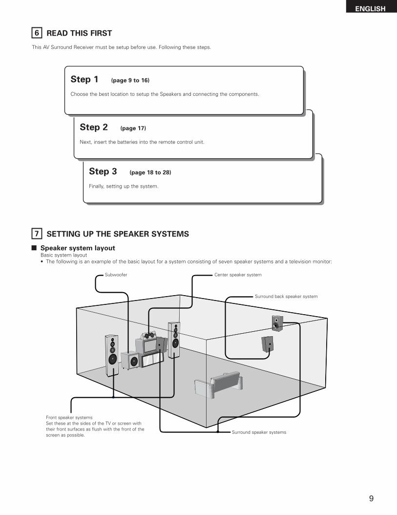
6 READ THIS FIRST
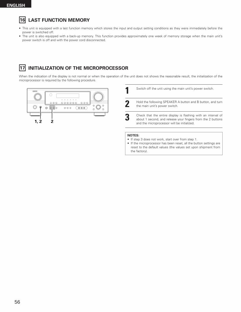
This AV Surround Receiver must be setup before use. Following these steps.
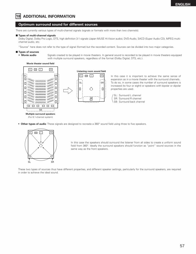
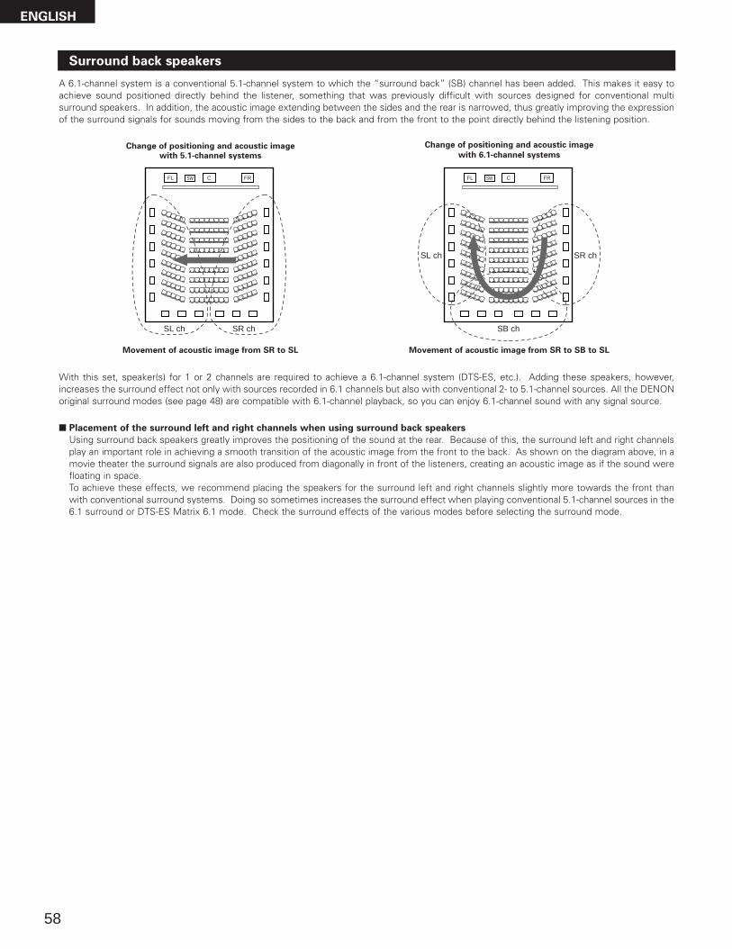
7 SETTING UP THE SPEAKER SYSTEMS
Step 3 (page 18 to 28)
Finally, setting up the system.
Step 2 (page 17)
Next, insert the batteries into the remote control unit.
Step 1 (page 9 to 16)
Choose the best location to setup the Speakers and connecting the components.
2 Speaker system layoutBasic system layout• The following is an example of the basic layout for a system consisting of seven speaker systems and a television monitor:
Subwoofer Center speaker system
Surround speaker systems
Surround back speaker system
Front speaker systemsSet these at the sides of the TV or screen withtheir front surfaces as flush with the front of thescreen as possible.
ENGLISH
10
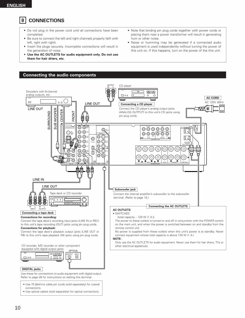
8 CONNECTIONS
• Do not plug in the power cord until all connections have beencompleted.
• Be sure to connect the left and right channels properly (left withleft, right with right).
• Insert the plugs securely. Incomplete connections will result inthe generation of noise.
• Use the AC OUTLETS for audio equipment only. Do not use
them for hair driers, etc.
• Note that binding pin plug cords together with power cords orplacing them near a power transformer will result in generatinghum or other noise.
• Noise or humming may be generated if a connected audioequipment is used independently without turning the power ofthis unit on. If this happens, turn on the power of the this unit.
Connecting the audio components
LINE OUT
SU
RR
OU
ND
SU
B W
OO
FER
CE
NT
ER
FRO
NT
LINE OUT
LINE OUT
LINE IN
ROUTPUTINPUT
L R L
ROUTPUT
L
R L
R LR L
LRLR
R L
RL
L
R
DIGITAL AUDIODIGITAL AUDIO
INPUTOUTPUT
OPTICALB
Connecting a CD player
Connect the CD player’s analog output jacks(ANALOG OUTPUT) to this unit’s CD jacks usingpin plug cords.
Decoders with 6-channel analog outputs, etc.
DIGITAL jacks
Use these for connections to audio equipment with digital output.Refer to page 26 for instructions on setting this terminal.
Connecting the AC OUTLETS
AC OUTLETS
• SWITCHED(total capacity – 120 W (1 A.))
The power to these outlets is turned on and off in conjunction with the POWER switchon the main unit, and when the power is switched between on and standby from theremote control unit. No power is supplied from these outlets when this unit’s power is at standby. Neverconnect equipment whose total capacity is above 120 W (1 A.)
NOTE:
Only use the AC OUTLETS for audio equipment. Never use them for hair driers, TVs orother electrical appliances.
AC CORD
AC 120V, 60Hz
Connect the internal amplifier’s subwoofer to the subwooferterminal. (Refer to page 15.)
Connecting a tape deck
Connections for recording:
Connect the tape deck’s recording input jacks (LINE IN or REC)to this unit’s tape recording (OUT) jacks using pin plug cords.Connections for playback:
Connect the tape deck’s playback output jacks (LINE OUT orPB) to this unit’s tape playback (IN) jacks using pin plug cords.
CD player
Tape deck or CD recorder
• Use 75 Ω/ohms cable pin cords (sold separately) for coaxialconnections.
• Use optical cables (sold separately) for optical connections.
Subwoofer jack
CD recorder, MD recorder or other componentequipped with digital output jacks.
ENGLISH
11
Connecting the video equipments
To connect the video signal, connect using a 75 Ω/ohms video signal cable cord. Using an improper cable can result in a drop in sound quality.
R OUTVIDEO
OPTICALOUT
L
AUDIOOUT
DIGITAL
INVIDEO
R
L
R
L
R
L
LR
R OUT IN
AUDIO VIDEOOUT IN
L R L
R L R L
LR
R OUTVIDEO
OPTICALOUT
L
AUDIOOUT
DIGITAL
LR
B
B
AU
DIO
OU
T
VID
EO
OU
T
VID
EO
IN
AU
DIO
OU
T
VID
EO
OU
T
AU
DIO
OU
T
AU
DIO
IN
VIDEO IN
VIDEO OUT
TV or DBS tuner
DVD player or VDP
Monitor TV
Connecting a TV/DBS tuner
TV/DBS
• Connect the TV’s or DBS tuner’s video output jack(VIDEO OUTPUT) to the (yellow) TV/DBS INjack using a 75 Ω/ohms video coaxial pin plug cord.
• Connect the TV’s or DBS tuner’s audio output jacks(AUDIO OUTPUT) to the TV/DBS IN jacksusing pin plug cords.
AUDIO
VIDEO
Connecting a DVD player or a video disc player (VDP)
• Connect the DVD player’s (video disc player’s) video output jack (VIDEO OUTPUT)to the (yellow) DVD/VDP IN jack using a 75 Ω/ohms video coaxial pin plugcord.
• Connect the DVD player’s (video disc player’s) analog audio output jacks(ANALOG AUDIO OUTPUT) to the DVD/VDP IN jacks using pin plugcords.
• For better sound quality, we recommend using the DVD player with digital ratherthan analog connections.DVD and VDP players can also be connected to the VCR terminals.
AUDIO
VIDEO
MONITOR OUT
• Connect the TV’s video input jack (VIDEOINPUT) to the MONITOR OUT jackusing a 75 Ω/ohms video coaxial pin plugcord.
VIDEO
NOTE:
Connection of the video disc Player Equipped with Dolby Digital RF Outputjack.• Please use a commercially available adaptor when connecting the Dolby
Digital RF output jack of the video disc player to the digital input jack.Please refer to the instruction manual of the adapter when makingconnections.
Video deck
Video input/output connections:
• Connect the video deck’s video output jack (VIDEO OUT) to the (yellow) VCR IN jack, and the video deck’s video input jack (VIDEO IN) to the (yellow)VCR OUT jack using 75 Ω/ohms video coaxial pin plug cords.
Connecting the audio output jacks:
• Connect the video deck’s audio output jacks (AUDIO OUT) to the VCR IN jacks, and the video deck’s audio input jacks (AUDIO IN) to the VCR OUTjacks using pin plug cords.
AUDIOAUDIO
VIDEOVIDEO
Connecting a video decks
ENGLISH
12
Connecting a video component equipped with S-video jacks
• When marking connections, also refer to the operating instructions of the other components.• A note on the S input jacks
The input selectors for the S inputs and pin jack inputs work in conjunction with each other.• Precaution when using S-jacks
This unit’s S-jacks (input and output) and video pin jacks (input and output) have independent circuit structures, so that video signals input fromthe S-jacks are only output from the S-jack outputs and video signals input from the pin jacks are only output from the pin jack outputs.When connecting this unit with equipment that is equipped with S-jacks, keep the above point in mind and make connections according to theequipment’s instruction manuals.
INS-VIDEO
OUTS-VIDEO
OUTS-VIDEO
OUT INS-VIDEO
VIDEO IN
VIDEO OUT
VID
EO
IN
VIDEO OUT
VID
EO
OU
T
B
B
DVD player, VDP, etc.
Connecting a DVD player or video disc player (VDP)
DVD/VDP
• Connect the DVD player’s or video disc player’s S-videooutput jack to the S-VIDEO DVD/VDP IN jack using an S-video connection cord.
Connecting a monitor TV
MONITOR OUT
• Connect the TV’s or DBS tuner’s S video input (S-VIDEO INPUT) to the MONITOR OUTjack using a S jack connection cord.
S-VIDEO
Monitor TV
Connecting a TV/DBS tuner
• Connect the TV’s or DBS tuner’s S-video output jack (S-VIDEOOUTPUT) to the TV/DBS IN jack using an S jackconnection cord.
S-VIDEO
TV or satellite broadcast tuner
Video deck
Connecting the video decks
• Connect the video deck’s S output jack (S-OUT) to the VCR INjack and the video deck’s S input jack (S-IN) to the VCR OUTjack using S jack connection cords.
S-VIDEO
S-VIDEO
Connect the components’ audio inputs and outputs as described on page 11.
R VIDEO OUTLOUTPUT
R VIDEO OUTLOUTPUT
LIN
E O
UT
VID
EO
OU
T
VIDEO OUTLINE OUT
L R
LR
LR
Connecting a Video game equipment
• Connect the Video game equipment’s output jacks to thisunit’s V. AUX INPUT jacks.
Video game
Video cameraConnecting a Video camera equipment
• Connect the video camera equipment’s output jacks to thisunit’s V. AUX INPUT jacks.
The V. AUX terminal is covered with a cap. Remove thiscap in order to use the terminal. (See page 4 for instructionson removing the cap.)
ENGLISH
13
VIDEO OUT
Y CRCB
COMPONENT
Y CRCB
VIDEO INCOMPONENT
B
Connecting the Video Component Equipped with Color Difference (Component - Y, PR/CR, PB/CB)
Video Jacks
• When making connections, also refer to the operating instructions of the other components.• The signals input to the color difference (component) video jacks are not outputs to the VIDEO output jack (yellow) or the S-Video output jack. • Some video sources with component video outputs are labeled Y, CB, CR or Y, Pb, Pr or Y, R-Y, B-Y. These terms all refer to component video
color difference output.
DVD player Connecting a DVD player
DVD IN jacks
• Connect the DVD player’s color difference (component) video output jacks(COMPONENT VIDEO OUTPUT) to the COMPONENT DVD IN jack using 75 Ω/ohmscoaxial video pin-plug cords.
• In the same way, another video source with component video outputs such as a TV/DBStuner, etc., can be connected to the TV/DBS color difference (component) video jacks.
Monitor TVConnecting a monitor TV
MONITOR OUT jack
• Connect the TV’s color difference (component) video input jacks (COMPONENT VIDEOINPUT) to the COMPONENT MONITOR OUT jack using 75 Ω/ohms coaxial video pin-plug cords.
• The color difference input jacks may be indicated differently onsome TVs, monitors or video components (“CR, CB and Y”, “R-Y, B-Y and Y”, “Pr, Pb and Y”, etc.). For details, carefully read theoperating instructions included with the TV or other component.
MONITOR OUT jacks
The AVR-1705/685 is equpped with a function for up-converting video signals.Because of this, the AVR-1705/685’s MONITOR OUT jack can be connected tothe monitor (TV) with a set of cables offering a higher quality connection,regardless of how the player and the AVR-1705/685’s video input jacks areconnected.Generally speaking, connections using the component video jacks offer tehighest quality playback, followed by connections using the S-Video jacks, thenconnections using regular video jacks (yellow).
NOTE:
Down-converting from the component video signal to the S-Video andcomposite video signal is not possible, so when not using the component videomonitor output terminal connect the player using the S-Video or compositevideo input terminal.
Cautions on the video conversion function:
When the component video terminals are used to connect the AVR-1705/685with a TV (or monitor, projector, etc.) and the video (yellow) or S-Video terminalsare used to connect the AVR-1705/685 with a VTR, depending on thecombination of the TV and VTR the picture may flicker in the horizontal direction,be distorted, be out of sync not display at all when playing video tapes.If this happens, connect a commercially available video stabilizer, etc., with aTBC (time base corrector) function between the AVR-1705/685 and the VTR, orif your VTR has a TBC function, turn it on.
(S-Video jack)
(Video jack) (Video jack)
(S-Video jack)
(Color Diffrence Video jack)(Color Diffrence Video jack)
The Video Conversion Function
With the AVR-1705/685, the Video signal and the S-videosignal which were inputted are converted mutually. And alsothe Video signal and the S-Video signal which were inputtedare converted into a higher quality.
This unit’s input jacks This unit’s output jacksThe flow of thethis unit’s internalsignals.
ENGLISH
14
1
4
23
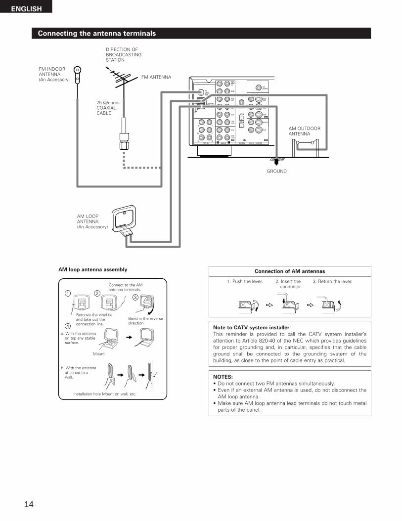
Connecting the antenna terminals
DIRECTION OF BROADCASTING STATION
AM LOOPANTENNA(An Accessory)
FM ANTENNA
GROUND
AM OUTDOORANTENNA
FM INDOOR ANTENNA(An Accessory)
75 Ω/ohms COAXIAL CABLE
AM loop antenna assembly
Connect to the AMantenna terminals.
Bend in the reversedirection.
Remove the vinyl tieand take out theconnection line.
a. With the antennaon top any stablesurface.
b. With the antennaattached to awall.
Mount
Installation hole Mount on wall, etc.
Connection of AM antennas
1. Push the lever. 2. Insert theconductor.
3. Return the lever.
Note to CATV system installer:
This reminder is provided to call the CATV system installer’sattention to Article 820-40 of the NEC which provides guidelinesfor proper grounding and, in particular, specifies that the cableground shall be connected to the grounding system of thebuilding, as close to the point of cable entry as practical.
NOTES:
• Do not connect two FM antennas simultaneously.• Even if an external AM antenna is used, do not disconnect the
AM loop antenna.• Make sure AM loop antenna lead terminals do not touch metal
parts of the panel.
ENGLISH
15
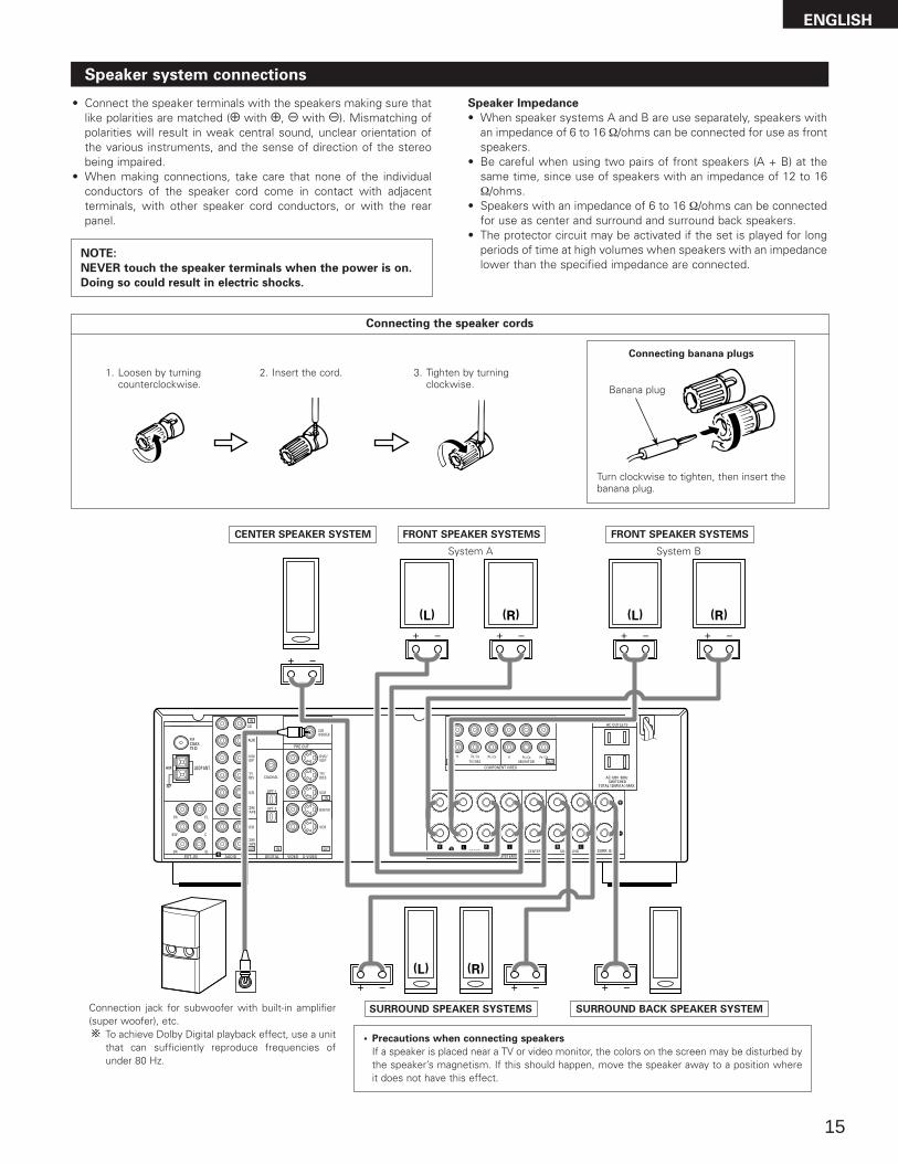
Speaker system connections
• Connect the speaker terminals with the speakers making sure thatlike polarities are matched (< with <, > with >). Mismatching ofpolarities will result in weak central sound, unclear orientation ofthe various instruments, and the sense of direction of the stereobeing impaired.
• When making connections, take care that none of the individualconductors of the speaker cord come in contact with adjacentterminals, with other speaker cord conductors, or with the rearpanel.
Speaker Impedance
• When speaker systems A and B are use separately, speakers withan impedance of 6 to 16 Ω/ohms can be connected for use as frontspeakers.
• Be careful when using two pairs of front speakers (A + B) at thesame time, since use of speakers with an impedance of 12 to 16Ω/ohms.
• Speakers with an impedance of 6 to 16 Ω/ohms can be connectedfor use as center and surround and surround back speakers.
• The protector circuit may be activated if the set is played for longperiods of time at high volumes when speakers with an impedancelower than the specified impedance are connected.
NOTE:
NEVER touch the speaker terminals when the power is on.
Doing so could result in electric shocks.
Connecting the speaker cords
1. Loosen by turning counterclockwise.
2. Insert the cord. 3. Tighten by turning clockwise.
Connecting banana plugs
Turn clockwise to tighten, then insert thebanana plug.
Banana plug
(L) (R)
(L) (R)(L) (R)
Connection jack for subwoofer with built-in amplifier(super woofer), etc.
To achieve Dolby Digital playback effect, use a unitthat can sufficiently reproduce frequencies ofunder 80 Hz.
SURROUND SPEAKER SYSTEMS
CENTER SPEAKER SYSTEM FRONT SPEAKER SYSTEMS
• Precautions when connecting speakers
If a speaker is placed near a TV or video monitor, the colors on the screen may be disturbed bythe speaker’s magnetism. If this should happen, move the speaker away to a position whereit does not have this effect.
System B
FRONT SPEAKER SYSTEMS
System A
SURROUND BACK SPEAKER SYSTEM
ENGLISH
16
Protector circuit
• This unit is equipped with a high-speed protection circuit. The purpose of this circuit is to protect the speakers undercircumstances such as when the output of the power amplifier is inadvertently short-circuited and a large current flows,when the temperature surrounding the unit becomes unusually high, or when the unit is used at high output over a longperiod which results in an extreme temperature rise. When the protection circuit is activated, the speaker output is cut off and the power supply indicator LED flashes. Shouldthis occur, please follow these steps: be sure to switch off the power of this unit, check whether there are any faults withthe wiring of the speaker cables or input cables, and wait for the unit to cool down if it is very hot. Improve the ventilationcondition around the unit and switch the power back on.If the protection circuit is activated again even though there are no problems with the wiring or the ventilation around theunit, switch off the power and contact a DENON service center.
Note on speaker impedance
• The protector circuit may be activated if the set is played for long periods of time at high volumes when speakers withan impedance lower than the specified impedance (for example speakers with an impedance of lower than 4 Ω/ohms)are connected. If the protector circuit is activated, the speaker output is cut off. Turn off the set’s power, wait for the setto cool down, improve the ventilation around the set, then turn the power back on.
ENGLISH
17
9 USING THE REMOTE CONTROL UNIT
Following the procedure outlined below, insert the batteries before using the remote control unit.
Range of operation of the remote control unit
Inserting the batteries
Point the remote control unit at the remote control sensor as shownon the diagram at the left.
NOTES:
• The remote control unit can be used from a straight distance ofapproximately 23 feet/7 meters, but this distance will shorten oroperation will become difficult if there are obstacles between theremote control unit and the remote control sensor, if the remotecontrol sensor is exposed to direct sunlight or other strong light, orif operated from an angle.
• Neon signs or other devices emitting pulse-type noise nearby mayresult in malfunction, so keep the set as far away from suchdevices as possible.Approx. 23 feet/7 m
30°30°
w Insert the R6P/AA batteries properly, asshown on the diagram.
q Press as shown by the arrow and slide off. e Close the lid.
NOTES:
• Use only R6P/AA batteries for replacement.• Be sure the polarities are correct. (See the illustration inside the battery compartment.)• Remove the batteries if the remote control transmitter will not be used for an extended period of time.• If batteries leak, dispose of them immediately. Avoid touching the leaked material or letting it come in contact with clothing, etc. Clean the
battery compartment thoroughly before installing new batteries.• Have replacement batteries on hand so that the old batteries can be replaced as quickly as possible when the time comes. • Even if less than a year has passed, replace the batteries with new ones if the set does not operate even when the remote control unit is
operated nearby the set. (The included battery is only for verifying operation. Replace it with a new battery as soon as possible.)
ENGLISH
18
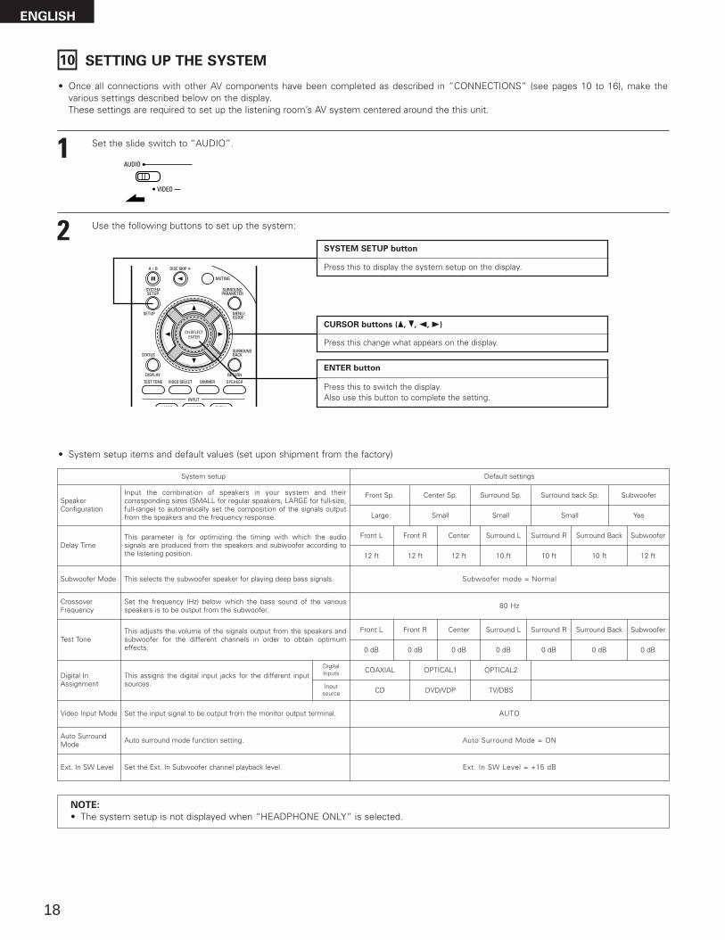
10 SETTING UP THE SYSTEM
• Once all connections with other AV components have been completed as described in “CONNECTIONS” (see pages 10 to 16), make thevarious settings described below on the display.These settings are required to set up the listening room’s AV system centered around the this unit.
SYSTEM SETUP button
Press this to display the system setup on the display.
CURSOR buttons (•, ª, 0, 1)
Press this change what appears on the display.
ENTER button
Press this to switch the display. Also use this button to complete the setting.
• System setup items and default values (set upon shipment from the factory)
System setup Default settings
SpeakerConfiguration
Subwoofer Mode
Digital InAssignment
Input the combination of speakers in your system and theircorresponding sizes (SMALL for regular speakers, LARGE for full-size,full-range) to automatically set the composition of the signals outputfrom the speakers and the frequency response.
This assigns the digital input jacks for the different inputsources. Input
source
DigitalInputs
Front Sp.
Large
Center Sp. Surround Sp. Subwoofer
Small Small Yes
CD DVD/VDP
COAXIAL OPTICAL1
Delay TimeThis parameter is for optimizing the timing with which the audiosignals are produced from the speakers and subwoofer according tothe listening position.
1 Set the slide switch to “AUDIO”.
2 Use the following buttons to set up the system:
This selects the subwoofer speaker for playing deep bass signals. Subwoofer mode = Normal
NOTE:
• The system setup is not displayed when “HEADPHONE ONLY” is selected.
CrossoverFrequency
Set the frequency (Hz) below which the bass sound of the variousspeakers is to be output from the subwoofer. 80 Hz
Auto SurroundMode Auto surround mode function setting. Auto Surround Mode = ON
Ext. In SW Level Set the Ext. In Subwoofer channel playback level. Ext. In SW Level = +15 dB
Surround back Sp.
Small
Front L Center Surround Back
12 ft 12 ft 10 ft
Subwoofer
12 ft
Front R
12 ft
Surround L
10 ft
Surround R
10 ft
Front L Front R Center
0 dB 0 dB 0 dBTest Tone
This adjusts the volume of the signals output from the speakers andsubwoofer for the different channels in order to obtain optimumeffects.
Surround L
0 dB
Surround R
0 dB
Surround Back
0 dB
Subwoofer
0 dB
Video Input Mode Set the input signal to be output from the monitor output terminal. AUTO
TV/DBS
OPTICAL2
ENGLISH
19
Before setting up the system
3
4 Press the SYSTEM SETUP button to enter the setting.
Turn on the power.Press the Power ON/STANDBY switch (button).
5 Press the ENTER or (down) button to switch to the speaker configuration set up.
*SYSTEM SET UP
NOTE:
Press the SYSTEM SETUP button again to finish system set up. System set up can be finished at any time. The changes to the settingsmade up to that point are entered.
NOTE: Please make sure the “AUDIO” position of the slide switch on the remote control unit.
(Main unit) (Remote control unit)
Setting the speaker configuration
1 Use the (left) and (right) buttons to select your front speaker type.
1 FRONT LARGELARGE SMALL
(left) button (right) button
Press the ENTER or (down) button to switch to the center speaker setting.
2 Use the (left) and (right) buttons to select your center speaker type.
2 CENTER SMALLLARGE SMALL NONE
(left) button (right) button
Press the ENTER or (down) button to switch to the surround speaker setting.
NOTE:
• When “Small” has been selected for the front speakers, “Large” cannot be selected for the center speaker.
(Initial)
(Initial)
2 Press the Power switch (button) .
(Main unit)
• ¢ ONThe power turns on and indicator is light.Set the power switch to this position to turn the power on and off from the included remote control unit.
• £ OFFThe power turns off and indicator is off.In this position, the power cannot be turned on and off from the remote control unit.
ENGLISH
1 Refer to “CONNECTIONS” (pages 10 to 16) and check that all connections are correct.
20
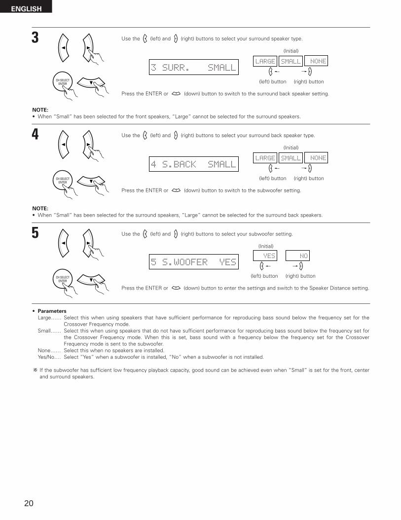
5 Use the (left) and (right) buttons to select your subwoofer setting.
5 S.WOOFER YESYES NO
(left) button (right) button
Press the ENTER or (down) button to enter the settings and switch to the Speaker Distance setting.
(Initial)
4 Use the (left) and (right) buttons to select your surround back speaker type.
4 S.BACK SMALLLARGE SMALL NONE
(left) button (right) button
Press the ENTER or (down) button to switch to the subwoofer setting.
(Initial)
NOTE:
• When “Small” has been selected for the surround speakers, “Large” cannot be selected for the surround back speakers.
3 Use the (left) and (right) buttons to select your surround speaker type.
3 SURR. SMALLLARGE SMALL NONE
(left) button (right) button
Press the ENTER or (down) button to switch to the surround back speaker setting.
(Initial)
NOTE:
• When “Small” has been selected for the front speakers, “Large” cannot be selected for the surround speakers.
ENGLISH
• Parameters
Large…… Select this when using speakers that have sufficient performance for reproducing bass sound below the frequency set for theCrossover Frequency mode.
Small…… Select this when using speakers that do not have sufficient performance for reproducing bass sound below the frequency set forthe Crossover Frequency mode. When this is set, bass sound with a frequency below the frequency set for the CrossoverFrequency mode is sent to the subwoofer.
None…… Select this when no speakers are installed.Yes/No…. Select “Yes” when a subwoofer is installed, “No” when a subwoofer is not installed.
If the subwoofer has sufficient low frequency playback capacity, good sound can be achieved even when “Small” is set for the front, centerand surround speakers.
21
3 Use the (left) and (right) buttons to set the distance from the center speaker to the listening position.
8 CENTER 12ft
• The number changes in units of 1 foot each time one of the buttons is pressed. Select the value closestto the measured distance.
Press the ENTER or (down) button to switch to the surround L speakers setting.
Setting the delay time
• Input the distance between the listening position and the different speakers to set the delay time for the surround mode.
Preparations:
Measure the distances between the listening position and the speakers (L1 to L5) on the diagram atthe right).
L1: Distance between center speaker and listening positionL2: Distance between front speakers and listening positionL3: Distance between surround speakers and listening positionL4: Distance between surround back speaker and listening positionL5: Distance between subwoofer and listening position
CAUTION:
Please note that the difference for every speaker should be 15 ft or less.
NOTE:
• No setting when “None” has been selected for the Speaker Configuration setting.
L1 L2
L5
L3 L4
Center FRFL
Subwoofer
SL
Listening position
SR
SB
1 Use the (left) and (right) buttons to set the distance from the front L speaker to the listening position.
6 FRONT L 12ft
• The number changes in units of 1 foot each time one of the buttons is pressed. Select the value closestto the measured distance.
Press the ENTER or (down) button to switch to the front R speaker setting.
2 Use the (left) and (right) buttons to set the distance from the front R speaker to the listening position.
7 FRONT R 12ft
• The number changes in units of 1 foot each time one of the buttons is pressed. Select the value closestto the measured distance.
Press the ENTER or (down) button to switch to the center speaker setting.
ENGLISH
22
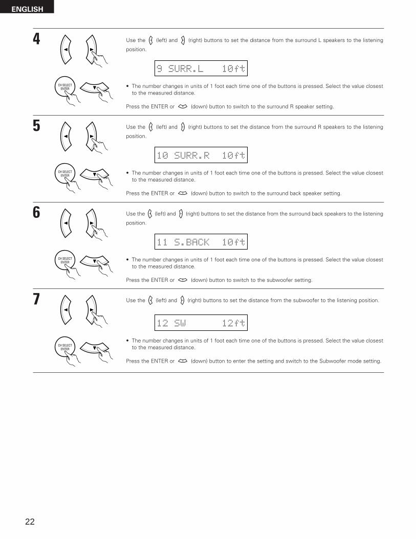
6 Use the (left) and (right) buttons to set the distance from the surround back speakers to the listening
position.
11 S.BACK 10ft
• The number changes in units of 1 foot each time one of the buttons is pressed. Select the value closestto the measured distance.
Press the ENTER or (down) button to switch to the subwoofer setting.
5 Use the (left) and (right) buttons to set the distance from the surround R speakers to the listening
position.
10 SURR.R 10ft
• The number changes in units of 1 foot each time one of the buttons is pressed. Select the value closestto the measured distance.
Press the ENTER or (down) button to switch to the surround back speaker setting.
7 Use the (left) and (right) buttons to set the distance from the subwoofer to the listening position.
12 SW 12ft
• The number changes in units of 1 foot each time one of the buttons is pressed. Select the value closestto the measured distance.
Press the ENTER or (down) button to enter the setting and switch to the Subwoofer mode setting.
4 Use the (left) and (right) buttons to set the distance from the surround L speakers to the listening
position.
9 SURR.L 10ft
• The number changes in units of 1 foot each time one of the buttons is pressed. Select the value closestto the measured distance.
Press the ENTER or (down) button to switch to the surround R speaker setting.
ENGLISH
23
NOTES:
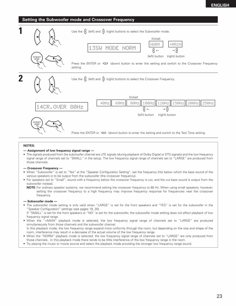
— Assignment of low frequency signal range —
• The signals produced from the subwoofer channel are LFE signals (during playback of Dolby Digital or DTS signals) and the low frequencysignal range of channels set to “SMALL” in the setup. The low frequency signal range of channels set to “LARGE” are produced fromthose channels.
— Crossover Frequency —
• When “Subwoofer” is set to “Yes” at the “Speaker Configuration Setting”, set the frequency (Hz) below which the bass sound of thevarious speakers is to be output from the subwoofer (the crossover frequency).
• For speakers set to “Small”, sound with a frequency below the crossover frequency is cut, and the cut bass sound is output from thesubwoofer instead.NOTE: For ordinary speaker systems, we recommend setting the crossover frequency to 80 Hz. When using small speakers, however,
setting the crossover frequency to a high frequency may improve frequency response for frequencies near the crossoverfrequency.
— Subwoofer mode —
• The subwoofer mode setting is only valid when “LARGE” is set for the front speakers and “YES” is set for the subwoofer in the“Speaker Configuration” settings (see pages 19, 20).If “SMALL” is set for the front speakers or “NO” is set for the subwoofer, the subwoofer mode setting does not affect playback of lowfrequency signal range.
• When the “+MAIN” playback mode is selected, the low frequency signal range of channels set to “LARGE” are producedsimultaneously from those channels and the subwoofer channel.In this playback mode, the low frequency range expand more uniformly through the room, but depending on the size and shape of theroom, interference may result in a decrease of the actual volume of the low frequency range.
• When the “NORM” playback mode is selected, the low frequency signal range of channels set to “LARGE” are only produced fromthose channels. In this playback mode there tends to be little interference of the low frequency range in the room.
• Try playing the music or movie source and select the playback mode providing the stronger low frequency range sound.
Setting the Subwoofer mode and Crossover Frequency
1 Use the (left) and (right) buttons to select the Subwoofer mode.
13SW MODE NORMNORM +MAIN
(left) button (right) button
Press the ENTER or (down) button to enter the setting and switch to the Crossover Frequencysetting.
(Initial)
2 Use the (left) and (right) buttons to select the Crossover Frequency.
Press the ENTER or (down) button to enter the setting and switch to the Test Tone setting.
(Initial)
ENGLISH
24
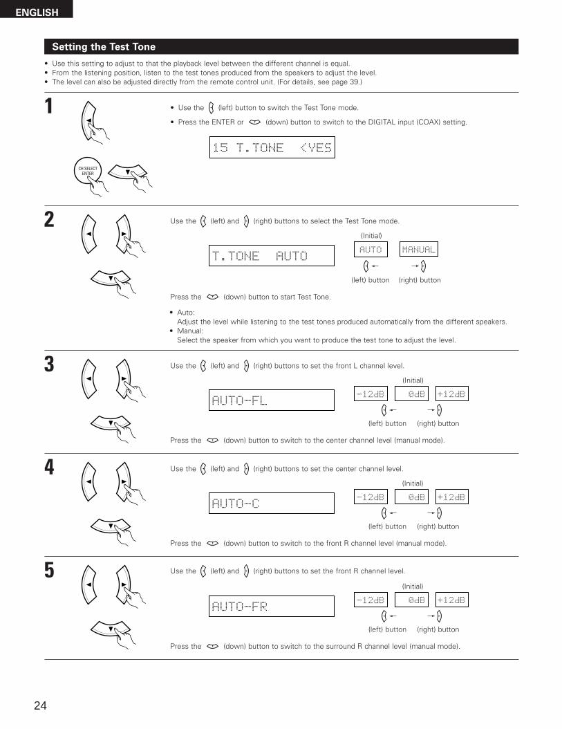
Setting the Test Tone
• Use this setting to adjust to that the playback level between the different channel is equal.• From the listening position, listen to the test tones produced from the speakers to adjust the level.• The level can also be adjusted directly from the remote control unit. (For details, see page 39.)
1 • Use the (left) button to switch the Test Tone mode.
• Press the ENTER or (down) button to switch to the DIGITAL input (COAX) setting.
15 T.TONE <YES
2 Use the (left) and (right) buttons to select the Test Tone mode.
T.TONE AUTOAUTO MANUAL
Press the (down) button to start Test Tone.
(left) button (right) button
3 Use the (left) and (right) buttons to set the front L channel level.
AUTO-FL-12dB 0dB +12dB
Press the (down) button to switch to the center channel level (manual mode).
(left) button (right) button
4 Use the (left) and (right) buttons to set the center channel level.
AUTO-C-12dB 0dB +12dB
Press the (down) button to switch to the front R channel level (manual mode).
(left) button (right) button
5 Use the (left) and (right) buttons to set the front R channel level.
AUTO-FR-12dB 0dB +12dB
Press the (down) button to switch to the surround R channel level (manual mode).
(left) button (right) button
(Initial)
• Auto:Adjust the level while listening to the test tones produced automatically from the different speakers.
• Manual:Select the speaker from which you want to produce the test tone to adjust the level.
(Initial)
(Initial)
(Initial)
ENGLISH
25
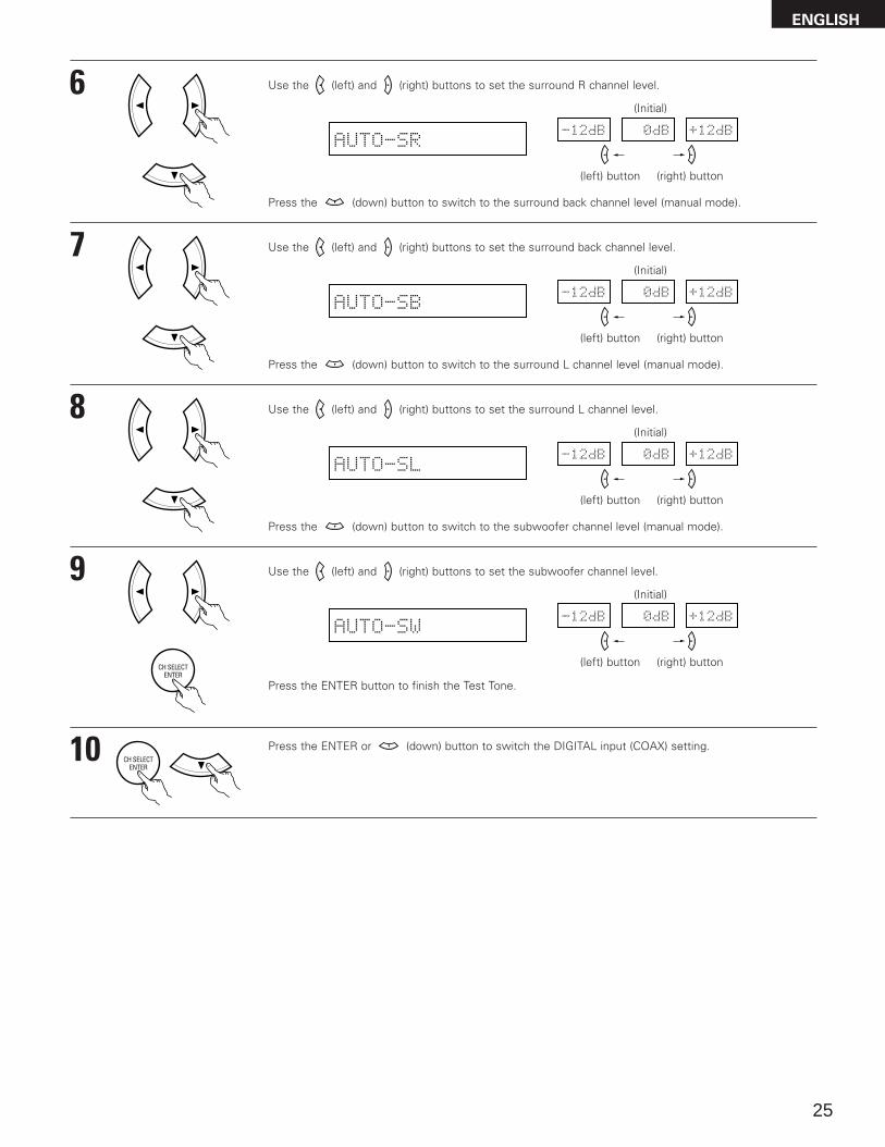
6 Use the (left) and (right) buttons to set the surround R channel level.
AUTO-SR-12dB 0dB +12dB
Press the (down) button to switch to the surround back channel level (manual mode).
(left) button (right) button
7 Use the (left) and (right) buttons to set the surround back channel level.
AUTO-SB-12dB 0dB +12dB
Press the (down) button to switch to the surround L channel level (manual mode).
(left) button (right) button
8 Use the (left) and (right) buttons to set the surround L channel level.
AUTO-SL-12dB 0dB +12dB
Press the (down) button to switch to the subwoofer channel level (manual mode).
(left) button (right) button
9 Use the (left) and (right) buttons to set the subwoofer channel level.
AUTO-SW-12dB 0dB +12dB
Press the ENTER button to finish the Test Tone.
(left) button (right) button
10 Press the ENTER or (down) button to switch the DIGITAL input (COAX) setting.
(Initial)
(Initial)
(Initial)
(Initial)
ENGLISH
26
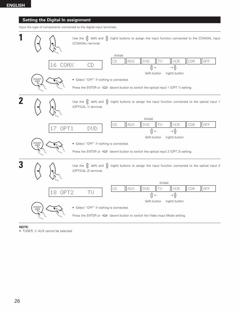
NOTE:
• TUNER, V. AUX cannot be selected.
Setting the Digital In assignment
Input the type of components connected to the digital input terminals.
1 Use the (left) and (right) buttons to assign the input function connected to the COAXIAL input
(COAXIAL) terminal.
16 COAX CDCD AUX DVD TV VCR CDR OFF
• Select “OFF” if nothing is connected.
Press the ENTER or (down) button to switch the optical input 1 (OPT 1) setting.
(left) button (right) button
2 Use the (left) and (right) buttons to assign the input function connected to the optical input 1
(OPTICAL 1) terminal.
17 OPT1 DVDCD AUX DVD TV VCR CDR OFF
• Select “OFF” if nothing is connected.
Press the ENTER or (down) button to switch the optical input 2 (OPT 2) setting.
(left) button (right) button
(Initial)
(Initial)
3 Use the (left) and (right) buttons to assign the input function connected to the optical input 2
(OPTICAL 2) terminal.
18 OPT2 TVCD AUX DVD TV VCR CDR OFF
• Select “OFF” if nothing is connected.
Press the ENTER or (down) button to switch the Video Input Mode setting.
(left) button (right) button
(Initial)
ENGLISH
27
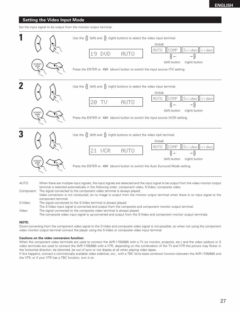
AUTO: When there are multiple input signals, the input signals are detected and the input signal to be output from the video monitor outputterminal is selected automatically in the following order: component video, S-Video, composite video.
Component: The signal connected to the component video terminal is always played.Video conversion is not conducted, so no image is output from the monitor output terminal when there is no input signal to thecomponent terminal.
S-Video: The signal connected to the S-Video terminal is always played.The S-Video input signal is converted and output from the composite and component monitor output terminal.
Video: The signal connected to the composite video terminal is always played.The composite video input signal is up-converted and output from the S-Video and component monitor output terminals.
NOTE:
Down-converting from the component video signal to the S-Video and composite video signal is not possible, so when not using the componentvideo monitor output terminal connect the player using the S-Video or composite video input terminal.
Cautions on the video conversion function:
When the component video terminals are used to connect the AVR-1705/685 with a TV (or monitor, projector, etc.) and the video (yellow) or Svideo terminals are used to connect the AVR-1705/685 with a VTR, depending on the combination of the TV and VTR the picture may flicker inthe horizontal direction, be distorted, be out of sync or not display at all when playing video tapes.If this happens, connect a commercially available video stabilizer, etc., with a TBC (time base corrector) function between the AVR-1705/685 andthe VTR, or if your VTR has a TBC function, turn it on.
Setting the Video Input Mode
Set the input signal to be output from the monitor output terminal.
1 Use the (left) and (right) buttons to select the video input terminal.
19 DVD AUTOAUTO videoSvideoCOMP
Press the ENTER or (down) button to switch the input source (TV) setting.
(left) button (right) button
2 Use the (left) and (right) buttons to select the video input terminal.
20 TV AUTOAUTO videoSvideoCOMP
Press the ENTER or (down) button to switch the input source (VCR) setting.
(left) button (right) button
(Initial)
(Initial)
3 Use the (left) and (right) buttons to select the video inpit terminal.
21 VCR AUTOAUTO videoSvideoCOMP
Press the ENTER or (down) button to switch the Auto Surround Mode setting.
(left) button (right) button
(Initial)
ENGLISH
28
After setting up the system
1 Press the SYSTEM SETUP button to finish system set up.
This completes the system setup operations. Once the system is set up, there is no need to make the settings again unless othercomponents or speakers are connected to or the speaker layout is changed.
Setting the Auto Surround Mode
For the three kinds of input signals as shown below, the surround mode played the last is stored in the memory. At next time it the same signalinputs, the memorized surround mode is automatically selected and the signal is played.Note that the surround mode setting is also stored separately for the different input function.
SIGNAL Default Auto Surround Mode
q Analog and PCM 2-channel signals STEREO
w 2-channel signals of Dolby Digital, DTS or other multichannel format Dolby PLIIx Cinema
e Multichannel signals of Dolby Digital, DTS or other multichannel format Dolby or DTS Surround
1 Use the (left) and (right) buttons to select the Auto Surround mode.
22 AUTOSURR. ON ON OFF
(left) button (right) button
Press the ENTER or (down) button to switch the Ext. In SW Level setting.
(Initial)
Setting the Ext. In SW Level
Set the method of playback of the analog input signal connected to the Ext. In terminal.
1 Use the (left) and (right) buttons to select the Ext. In Subwoofer channel Level playback.
23 EXT.IN SW +15 +00 +05 +10 +15
(left) button (right) button
Press the ENTER or (down) button if you want to start the settings over from the beginning.
(Initial)
ENGLISH
29
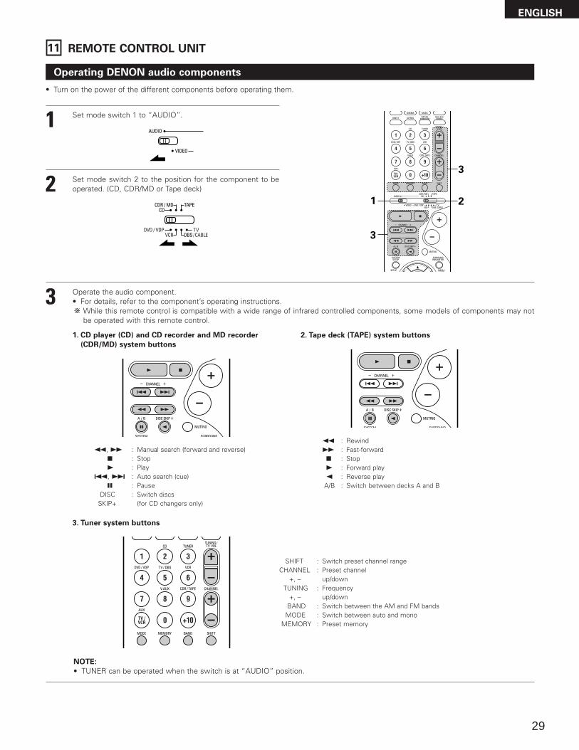
Operating DENON audio components
• Turn on the power of the different components before operating them.
1
2
3
Set mode switch 1 to “AUDIO”.
Set mode switch 2 to the position for the component to beoperated. (CD, CDR/MD or Tape deck)
Operate the audio component.• For details, refer to the component’s operating instructions.
While this remote control is compatible with a wide range of infrared controlled components, some models of components may notbe operated with this remote control.
1. CD player (CD) and CD recorder and MD recorder
(CDR/MD) system buttons
3. Tuner system buttons
2. Tape deck (TAPE) system buttons
3
21
3
6, 7 : Manual search (forward and reverse)2 : Stop1 : Play
• TUNER can be operated when the switch is at “AUDIO” position.
11 REMOTE CONTROL UNIT
ENGLISH
30
Preset memory
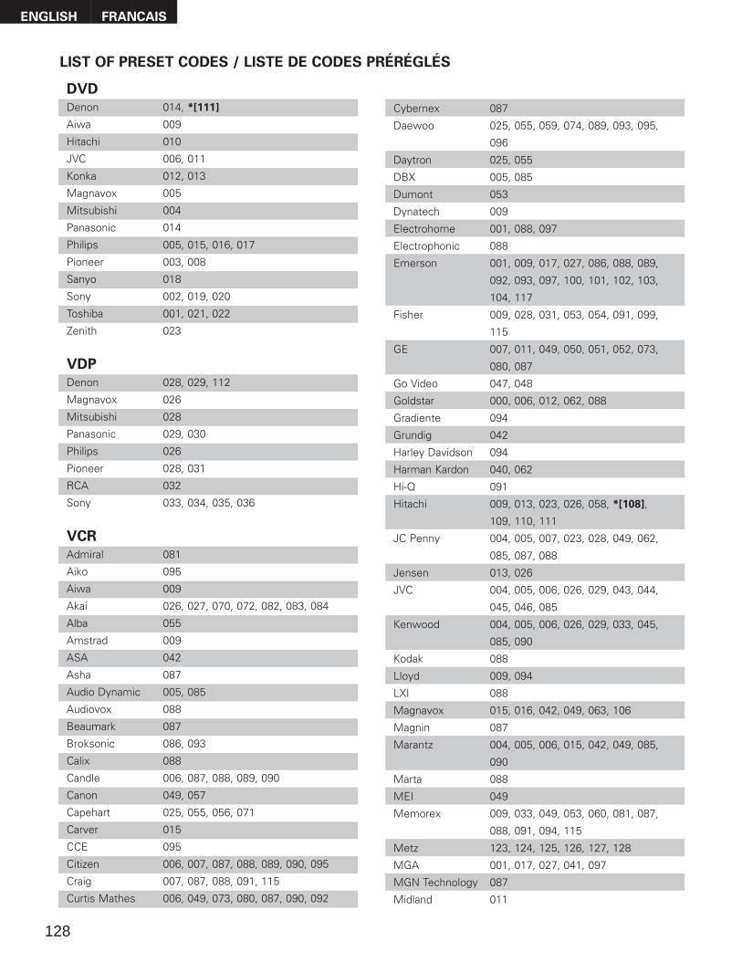
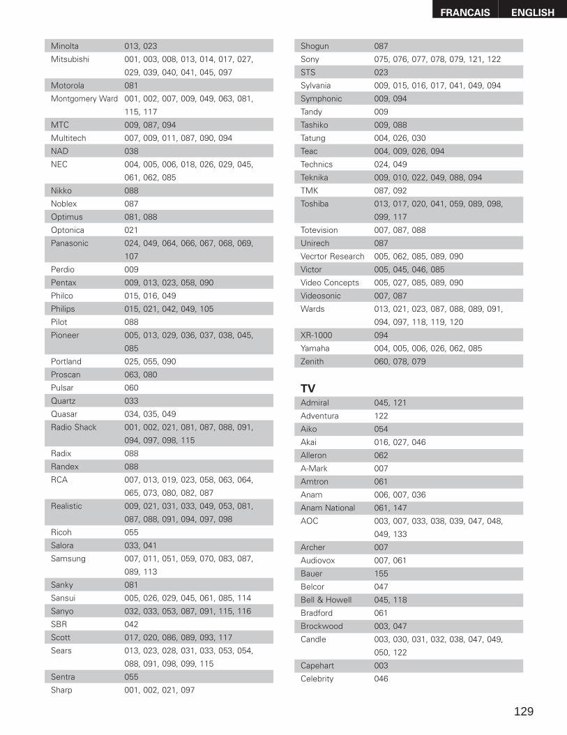
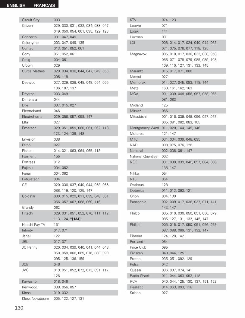
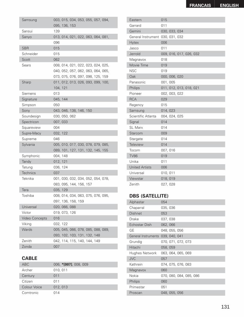
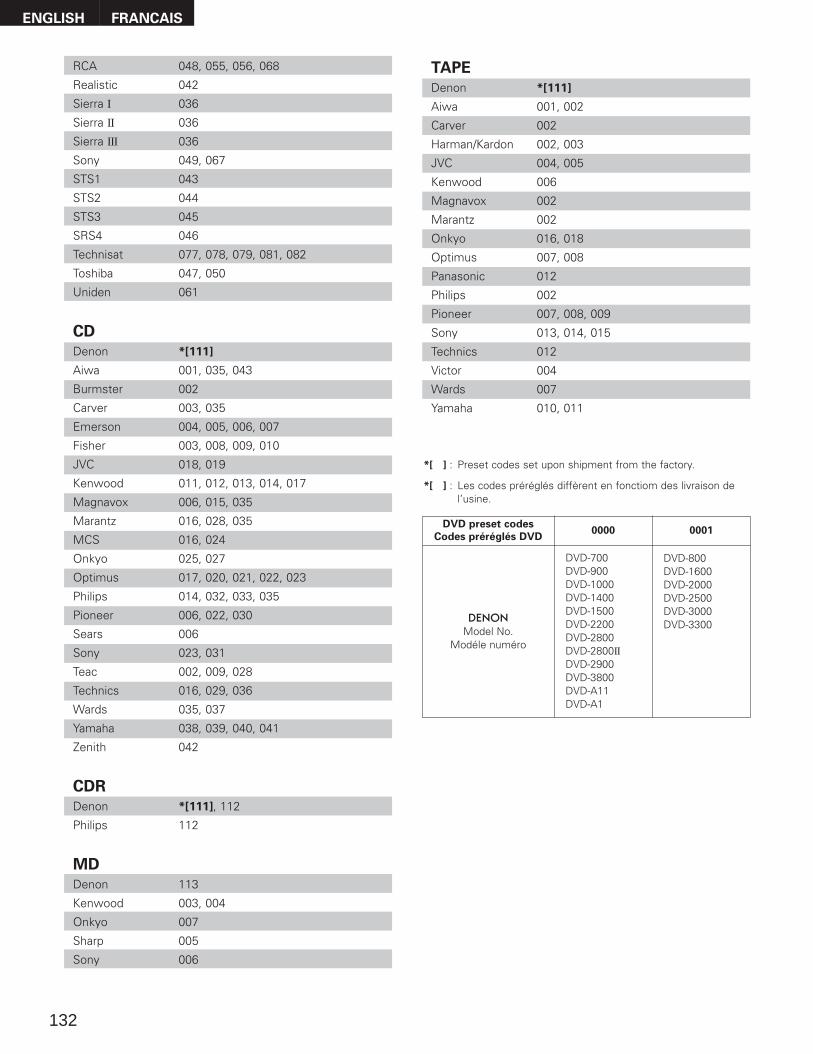
DENON and other makes of components can be operated by setting the preset memory.This remote control unit can be used to operate components of other manufacturers by registering themanufacturer of the component as shown on the List of Preset Codes (pages 128~132).Operation is not possible for some models.
1
2
Set mode switch 1 to “AUDIO” or “VIDEO”.
Set mode switch 2 to the component to be registered.
3
21
4Set the AUDIO side for the CD, Tape deck or CDR/MDposition, to the VIDEO side for the DVD/VDP, DBS/CABLE,VCR or TV position.
3 Press the ON/SOURCE button and the OFF button at thesame time.
• Indicator flash.
4
5
Referring to the included List ofPreset Codes, use the numberbuttons to input the preset code (a3-digit number) for the manufacturerof the component whose signalsyou want to store in the memory.
To store the codes of another component in the memory,repeat steps 1 to 4.
The preset codes are as follows upon shipment from the factory and after resetting:TV, VCR.....................................................HITACHICD, TAPE ..................................................DENONCDR/MD ...................................................DENON (CDR)DVD/VDP ..................................................DENON (DVD)DBS/CABLE ..............................................ABC (CABLE)
NOTES:
• The signals for the pressed buttons are emitted while setting the preset memory. To avoid accidental operation, cover the remote controlunit’s transmitting window while setting the preset memory.
• Depending on the model and year of manufacture, this function cannot be used for some models, even if they are of makes listed on theincluded list of preset codes.
• Some manufacturers use more than one type of remote control code. Refer to the included list of preset codes to change the numberand check.
• The preset memory can be set for one component only among the following: CDR/MD, DVD/VDP and DBS/CABLE.
1 2 3
4 5 6
7 8 9
0
ENGLISH
31
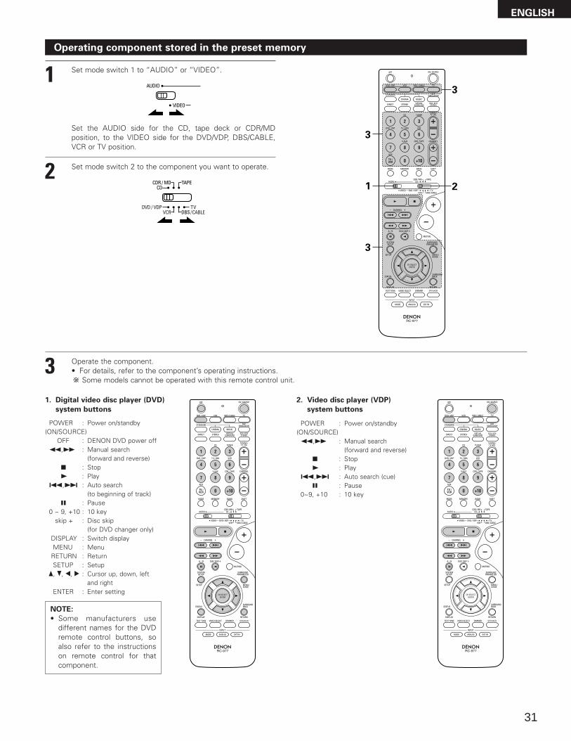
Operating component stored in the preset memory
1
2
Set mode switch 1 to “AUDIO” or “VIDEO”.
Set mode switch 2 to the component you want to operate.
3
21
3
3
Set the AUDIO side for the CD, tape deck or CDR/MDposition, to the VIDEO side for the DVD/VDP, DBS/CABLE,VCR or TV position.
1. Digital video disc player (DVD)
system buttons
POWER : Power on/standby(ON/SOURCE)
OFF : DENON DVD power off6,7 : Manual search
(forward and reverse)2 : Stop1 : Play
8,9 : Auto search (to beginning of track)
3 : Pause0 ~ 9, +10 : 10 key
skip + : Disc skip(for DVD changer only)
DISPLAY : Switch displayMENU : Menu
RETURN : ReturnSETUP : Setup
•, ª, 0, 1 : Cursor up, down, leftand right
ENTER : Enter setting
2. Video disc player (VDP)
system buttons
POWER : Power on/standby(ON/SOURCE)6,7 : Manual search
(forward and reverse)2 : Stop1 : Play
8,9 : Auto search (cue)3 : Pause
0~9, +10 : 10 key
3 Operate the component.• For details, refer to the component’s operating instructions.
Some models cannot be operated with this remote control unit.
NOTE:
• Some manufacturers usedifferent names for the DVDremote control buttons, soalso refer to the instructionson remote control for thatcomponent.
ENGLISH
32
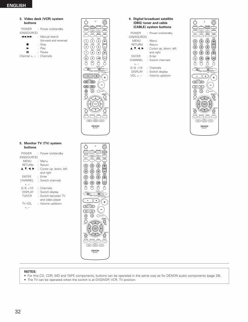
3. Video deck (VCR) system
buttons
4. Digital broadcast satellite
(DBS) tuner and cable
(CABLE) system buttonsPOWER : Power on/standby
(ON/SOURCE)6,7 : Manual search
(forward and reverse)2 : Stop1 : Play3 : Pause
Channel +, – : Channels
POWER : Power on/standby(ON/SOURCE)
MENU : MenuRETURN : Return•, ª, 0, 1 : Cursor up, down, left
and rightENTER : Enter
CHANNEL : Switch channels+, –
0~9, +10 : ChannelsDISPLAY : Switch display
VOL +, – : Volume up/down
5. Monitor TV (TV) system
buttons
POWER : Power on/standby(ON/SOURCE)
MENU : MenuRETURN : Return•, ª, 0, 1 : Cursor up, down, left
and rightENTER : Enter
CHANNEL : Switch channels+, –
0~9, +10 : ChannelsDISPLAY : Switch displayTV/VCR : Switch between TV
and video playerTV VOL : Volume up/down
+, –
NOTES:
• For this CD, CDR, MD and TAPE components, buttons can be operated in the same way as for DENON audio components (page 29).• The TV can be operated when the switch is at DVD/VDP, VCR, TV position.
ENGLISH
33
Table 1
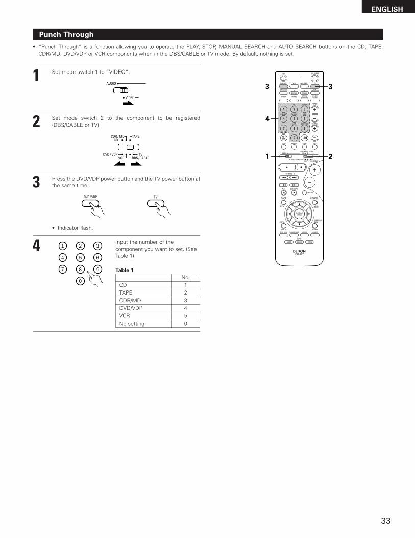
Punch Through
• “Punch Through” is a function allowing you to operate the PLAY, STOP, MANUAL SEARCH and AUTO SEARCH buttons on the CD, TAPE,CDR/MD, DVD/VDP or VCR components when in the DBS/CABLE or TV mode. By default, nothing is set.
1
2
Set mode switch 1 to “VIDEO”.
Set mode switch 2 to the component to be registered(DBS/CABLE or TV).
3
21
4
3
3 Press the DVD/VDP power button and the TV power button atthe same time.
• Indicator flash.
4 Input the number of thecomponent you want to set. (SeeTable 1)
1 2 3
4 5 6
7 8 9
0CDTAPECDR/MDDVD/VDPVCRNo setting
No.123450
ENGLISH
34
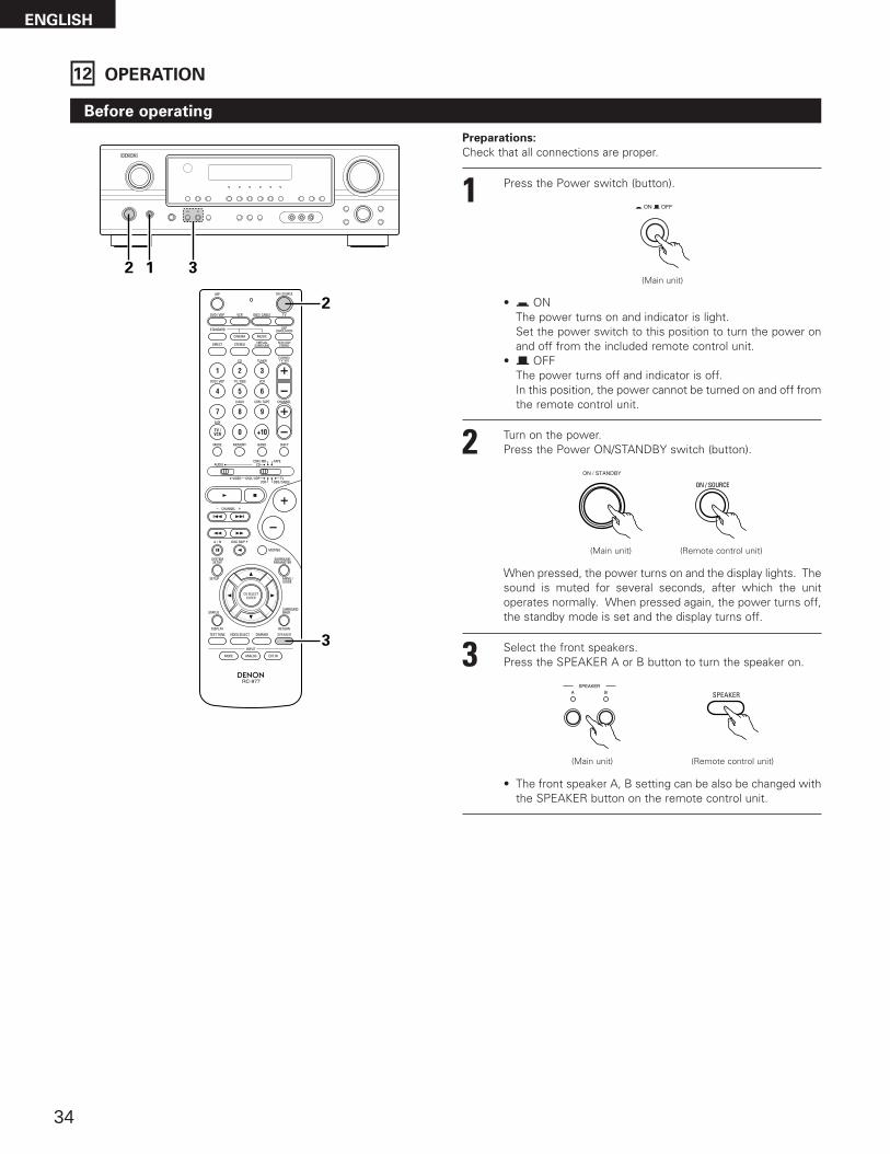
12 OPERATION
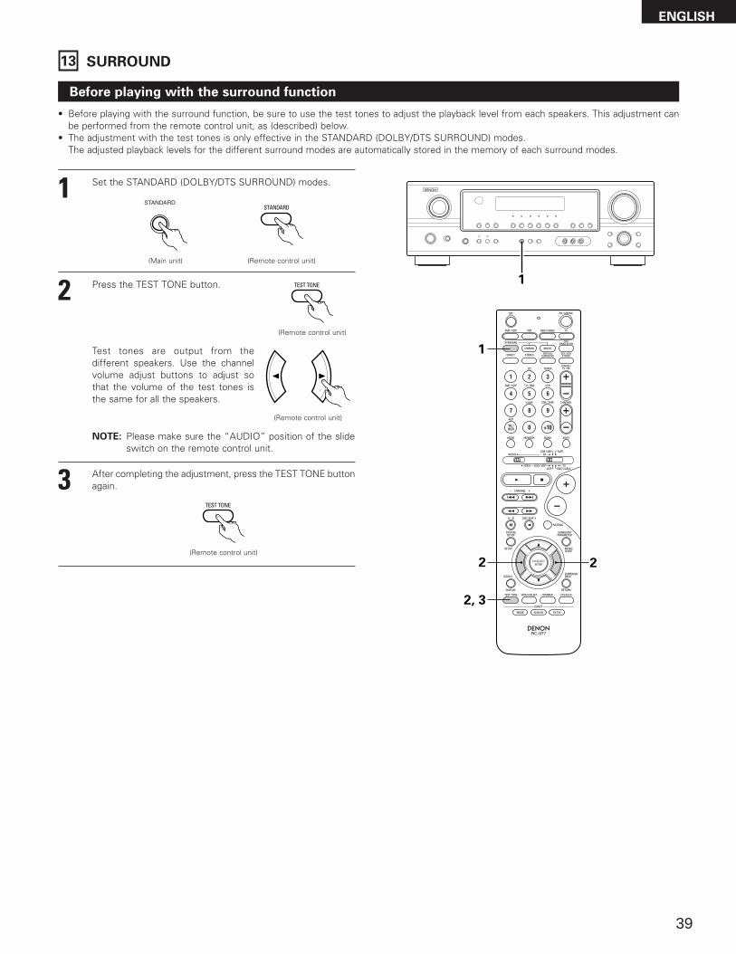
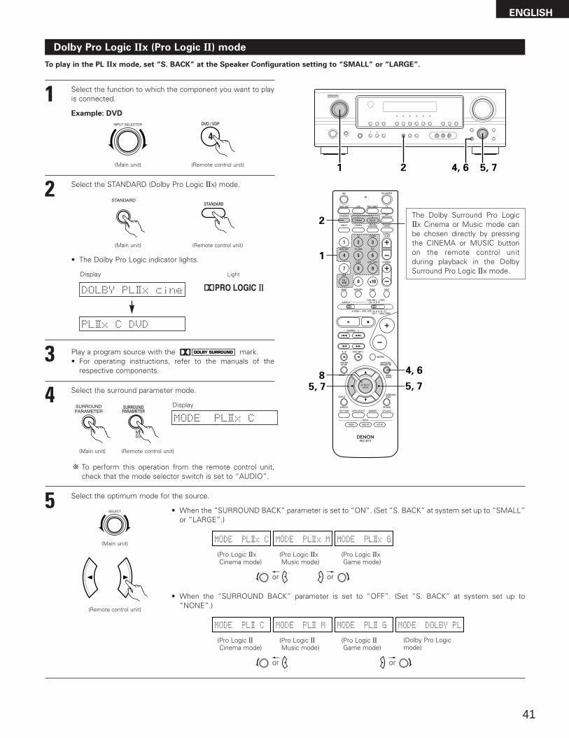
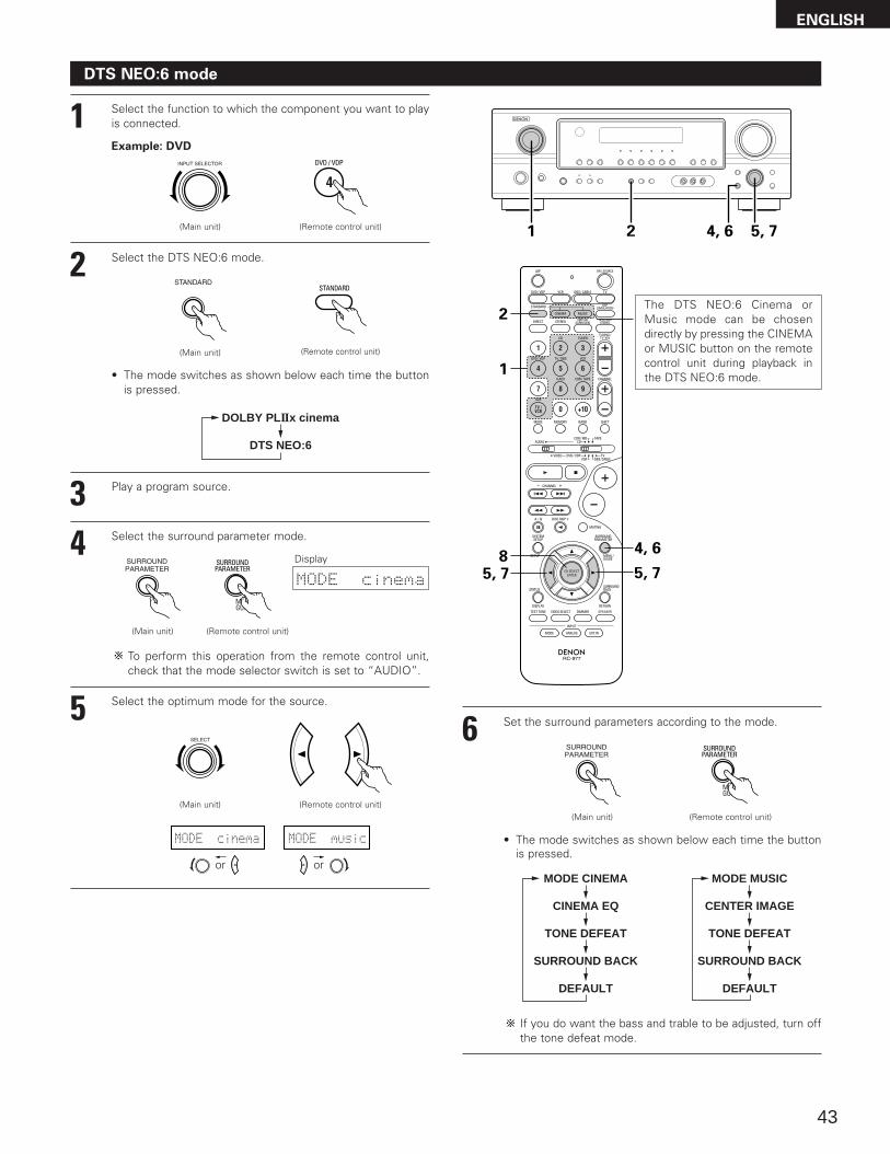
Before operating
Preparations:
Check that all connections are proper.
2 Turn on the power.Press the Power ON/STANDBY switch (button).
3 Select the front speakers.Press the SPEAKER A or B button to turn the speaker on.
(Main unit) (Remote control unit)
2 1 3
2
3
When pressed, the power turns on and the display lights. Thesound is muted for several seconds, after which the unitoperates normally. When pressed again, the power turns off,the standby mode is set and the display turns off.
(Main unit) (Remote control unit)
• The front speaker A, B setting can be also be changed withthe SPEAKER button on the remote control unit.
1 Press the Power switch (button).
(Main unit)
• ¢ ONThe power turns on and indicator is light.Set the power switch to this position to turn the power onand off from the included remote control unit.
• £ OFFThe power turns off and indicator is off.In this position, the power cannot be turned on and off fromthe remote control unit.
ENGLISH
35
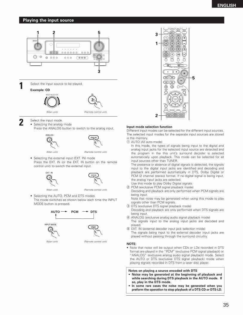
Playing the input source
3
1 2 5
Input mode selection function
Different input modes can be selected for the different input sources.The selected input modes for the separate input sources are storedin the memory.q AUTO (All auto mode)
In this mode, the types of signals being input to the digital andanalog input jacks for the selected input source are detected andthe program in the this unit’s surround decoder is selectedautomatically upon playback. This mode can be selected for allinput sources other than TUNER.The presence or absence of digital signals is detected, the signalsinput to the digital input jacks are identified and decoding andplayback are performed automatically in DTS, Dolby Digital orPCM (2 channel stereo) format. If no digital signal is being input,the analog input jacks are selected.Use this mode to play Dolby Digital signals.
w PCM (exclusive PCM signal playback mode)Decoding and playback are only performed when PCM signals arebeing input.Note that noise may be generated when using this mode to playsignals other than PCM signals.
e DTS (exclusive DTS signal playback mode)Decoding and playback are only performed when DTS signals arebeing input.
r ANALOG (exclusive analog audio signal playback mode)The signals input to the analog input jacks are decoded andplayed.
t EXT. IN (external decoder input jack selection mode)The signals being input to the external decoder input jacks areplayed without passing through the surround circuitry.
NOTE:
• Note that noise will be output when CDs or LDs recorded in DTSformat are played in the “PCM” (exclusive PCM signal playback) or“ANALOG” (exclusive analog audio signal playback) mode. Selectthe AUTO or DTS (exclusive DTS signal playback) mode whenplaying signals recorded in DTS from a laser disc player.
Notes on playing a source encoded with DTS
• Noise may be generated at the beginning of playback and
while searching during DTS playback in the AUTO mode. If
so, play in the DTS mode.
• In some rare cases the noise may be generated when you
preform the operation to stop playback of a DTS-CD or DTS-LD.
5
1
3
2
1 Select the input source to be played.
Example: CD
(Main unit) (Remote control unit)
2 Select the input mode.• Selecting the analog mode
Press the ANALOG button to switch to the analog input.
(Remote control unit)
• Selecting the external input (EXT. IN) modePress the EXT. IN (or the EXT. IN button on the remotecontrol unit) to switch the external input.
(Main unit) (Remote control unit)
• Selecting the AUTO, PCM and DTS modesThe mode switches as shown below each time the INPUTMODE button is pressed.
AUTO PCM DTS
(Main unit)
(Main unit) (Remote control unit)
ENGLISH
36
• To increase the bass or treble: Turn the control clockwise.(The bass or treble sound can be increased to up to +12 dBin steps of 2 dB.)
• To decrease the bass or treble: Turn the controlcounterclockwise. (The bass or treble sound can bedecreased to up to –12 dB in steps of 2 dB.)
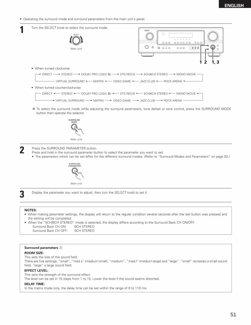
To select the surround mode while adjustingthe surround parameters, tone defeat ortone control, press the surround modebutton then operate the selector.
3 Select the play mode.Press the SURROUND MODE button, then turn the SELECTknob.
Example: Stereo
(Main unit) (Remote control unit)
4 Start playback on the selected component.• For operating instructions, refer to the component’s manual.
5 Adjust the volume.
(Main unit) (Remote control unit)
The volume level isdisplayed on themaster volume leveldisplay.
The volume can be adjusted within the range of –70 to 0 to 18 dB,in steps of 1 dB. However, when the channel level is set asdescribed on page 39, if the volume for any channel is set at +1 dBor greater, the volume cannot be adjusted up to 18 dB. (In this casethe maximum volume is adjusted to “18 dB — (Maximum value ofchannel level)”.)
Input mode when playing DTS sources• Noise will be output if DTS-compatible CDs or LDs are played in the
“ANALOG” or “PCM” mode.When playing DTS-compatible sources, be sure to connect thesource component to the digital input jacks (OPTICAL/COAXIAL)and set the input mode to “DTS”.
Input mode display
ANALOGDIGITAL
DIGITAL
DIGITAL
ANALOG
AUTO PCM DTSINPUT
AUTO PCM DTSINPUT
AUTO PCM DTSINPUT
AUTO PCM DTSINPUT
• In the AUTO mode
• In the DIGITAL PCM mode
• In the DIGITAL DTS mode
• In the ANALOG mode
One of these lights, depending onthe input signal.
Input signal display
SIGNAL
DIGITAL
DIGITAL
DIGITAL
SIGNAL
SIGNAL
• DOLBY DIGITAL
• DTS
• PCM
The indicator lights when digital signals are being input
properly. If the indicator does not light, check whether
the digital input component setup (page 26) and connections are
correct and whether the component’s power is turned on.
DIGITAL
DIGITAL
NOTE:
• The indicator will light when playing CD-ROMscontaining data other than audio signals, but no sound will beheard.
DIGITAL
After starting playback
[1] Adjusting the sound quality (tone)
1 The tone switches as follows each time the TONE CONTROLbutton is pressed.
BASS TREBLE
2 With the name of the volume to beadjusted selected, turn the SELECTknob to adjust the level.
32 1
(Main unit)
(Main unit)
3 If you do not want the bass and treble to be adjusted, turn onthe tone defeat mode.
The signals do not pass through thebass and treble adjustment circuits,so it provides higher quality sound.
(Main unit)
(Main unit)
ENGLISH
37
Using the dimmer function• Use this to change the brightness of the
display.The display brightness changes in foursteps (bright, medium, dim and off) bypressing the main unit’s DIMMER buttonrepeatedly.
Front panel display• Descriptions of the unit’s operations are
also displayed on the front panel display.In addition, the display can be switched tocheck the unit’s operating status whileplaying a source by pressing the STATUSbutton.
Simulcast playbackUse this switch to monitor a video sourceother than the audio source.Press the VIDEO SELECT button repeatedlyuntil the desired source appears on thedisplay.
Cancelling simulcast playback.• Select “SOURCE” using the video
select button.• Switch the program source to the
component connected to the videoinput jacks.
[3] Turning the sound off temporarily (muting)
1 Use this to turn off the audio outputtemporarily.Press the MUTING button.
Cancelling MUTING mode.• Press the MUTING button again.• Muting will also be cancelled when MASTER VOL is
adjusted up or down.
[4] Combining the currently playing sound with the desired image
1
[5] Checking the currently playing program source, etc.
1(Main unit)
(Remote control unit)
1
1
2
2 1
[2] Listening over headphones NOTE:
To prevent hearing loss, do not raise the volume level excessivelywhen using headphones.1 Plug the headphones’ plug into the
jack.
Connect the headphones to thePHONES jack. The speaker output is automaticallyturned off when headphones areconnected.
1
PHONES
(Main unit)
(Remote control unit)
1
1
2(Main unit)
BRIGHT MEDIUM
OFF
DIM
(Remote control unit)
ENGLISH
38
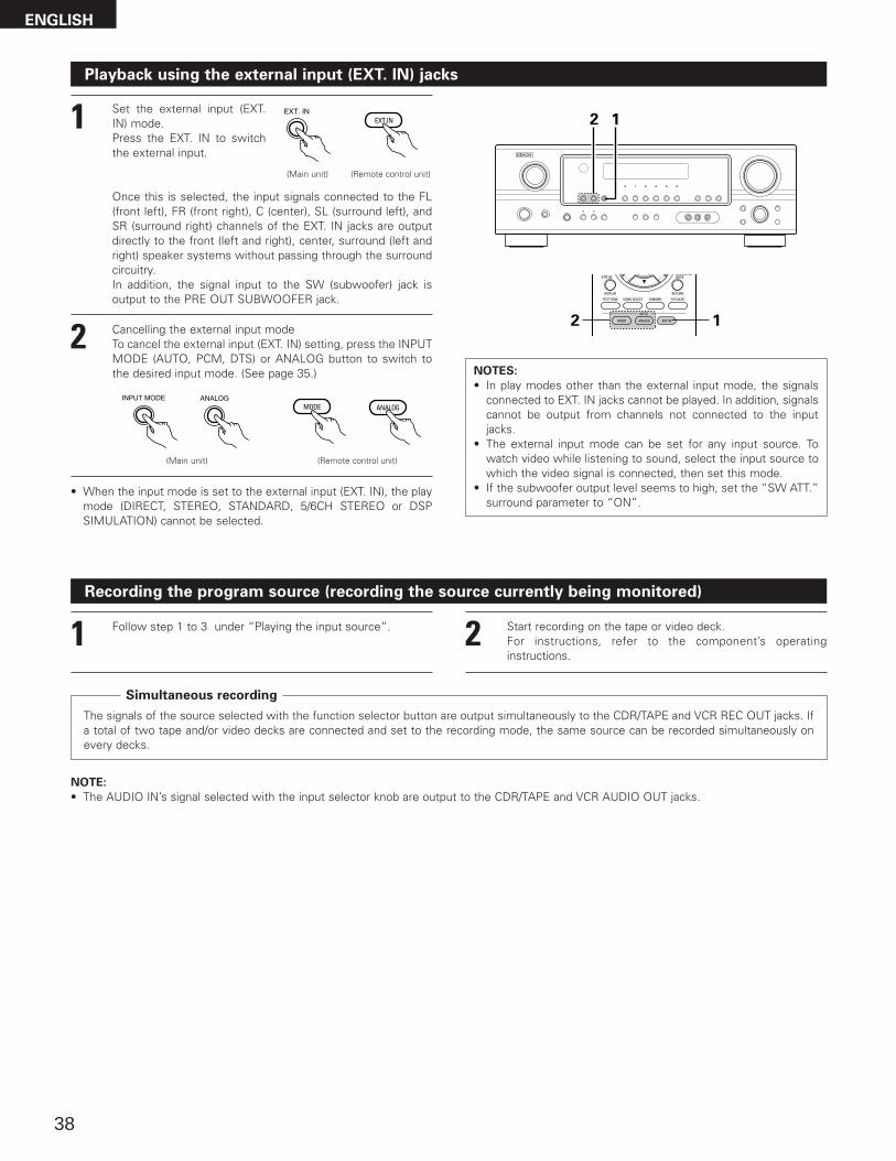
Set the external input (EXT.IN) mode.Press the EXT. IN to switchthe external input.
Once this is selected, the input signals connected to the FL(front left), FR (front right), C (center), SL (surround left), andSR (surround right) channels of the EXT. IN jacks are outputdirectly to the front (left and right), center, surround (left andright) speaker systems without passing through the surroundcircuitry.In addition, the signal input to the SW (subwoofer) jack isoutput to the PRE OUT SUBWOOFER jack.
Playback using the external input (EXT. IN) jacks
1(Main unit) (Remote control unit)
2 Cancelling the external input modeTo cancel the external input (EXT. IN) setting, press the INPUTMODE (AUTO, PCM, DTS) or ANALOG button to switch tothe desired input mode. (See page 35.)
(Remote control unit)(Main unit)
• When the input mode is set to the external input (EXT. IN), the playmode (DIRECT, STEREO, STANDARD, 5/6CH STEREO or DSPSIMULATION) cannot be selected.
NOTES:
• In play modes other than the external input mode, the signalsconnected to EXT. IN jacks cannot be played. In addition, signalscannot be output from channels not connected to the inputjacks.
• The external input mode can be set for any input source. Towatch video while listening to sound, select the input source towhich the video signal is connected, then set this mode.
• If the subwoofer output level seems to high, set the “SW ATT.”surround parameter to “ON”.
2 1
2 1
Recording the program source (recording the source currently being monitored)
1 Follow step 1 to 3 under “Playing the input source”.
The signals of the source selected with the function selector button are output simultaneously to the CDR/TAPE and VCR REC OUT jacks. Ifa total of two tape and/or video decks are connected and set to the recording mode, the same source can be recorded simultaneously onevery decks.
NOTE:
• The AUDIO IN’s signal selected with the input selector knob are output to the CDR/TAPE and VCR AUDIO OUT jacks.
2 Start recording on the tape or video deck.For instructions, refer to the component’s operatinginstructions.
Simultaneous recording
ENGLISH
39
13 SURROUND
Before playing with the surround function
• Before playing with the surround function, be sure to use the test tones to adjust the playback level from each speakers. This adjustment canbe performed from the remote control unit, as (described) below.
• The adjustment with the test tones is only effective in the STANDARD (DOLBY/DTS SURROUND) modes. The adjusted playback levels for the different surround modes are automatically stored in the memory of each surround modes.
1 Set the STANDARD (DOLBY/DTS SURROUND) modes.
2 Press the TEST TONE button.
3 After completing the adjustment, press the TEST TONE buttonagain.
(Main unit) (Remote control unit)
(Remote control unit)
Test tones are output from thedifferent speakers. Use the channelvolume adjust buttons to adjust sothat the volume of the test tones isthe same for all the speakers.
(Remote control unit)
1
2
2, 3
2
1
(Remote control unit)
NOTE: Please make sure the “AUDIO” position of the slideswitch on the remote control unit.
ENGLISH
40
• After adjusting using the test tones, adjust the channel levels either according to the playback sources or to suit your tastes, as (described)below.
1 Select the speaker whose level you want to adjust.
The channel switches as shown below each time the buttonis pressed.
3 Adjust the level of the selected speaker.
FL CNTR FR SR SB
SW SL
(Remote control unit)
(Remote control unit)
3
1, 2
3NOTE: Please make sure the “AUDIO” position of the slide
switch on the remote control unit.
Default setting of channel level is 0 dB.The level of the selected speaker can be adjusted withinthe range of +12 to –12 dB using cursor buttons.SW channel level can be turned off by decreasing one stepfrom –12 dB.
OFF ´ –12 dB ´ 12 dB
2
(Remote control unit)
ENGLISH
41
Dolby Pro Logic IIx (Pro Logic II) mode
2 Select the STANDARD (Dolby Pro Logic IIx) mode.
Light
(Main unit) (Remote control unit)
3 Play a program source with the mark.• For operating instructions, refer to the manuals of the
respective components.
5, 74, 61 2
4, 6
5, 7
1
85, 7
2
4 Select the surround parameter mode.
1 Select the function to which the component you want to playis connected.
Example: DVD
(Main unit) (Remote control unit)
Display
(Main unit) (Remote control unit)
To perform this operation from the remote control unit,check that the mode selector switch is set to “AUDIO”.
Display
5 Select the optimum mode for the source.
(Main unit)
(Remote control unit)
• The Dolby Pro Logic indicator lights.
The Dolby Surround Pro LogicIIx Cinema or Music mode canbe chosen directly by pressingthe CINEMA or MUSIC buttonon the remote control unitduring playback in the DolbySurround Pro Logic IIx mode.
To play in the PL IIx mode, set “S. BACK” at the Speaker Configuration setting to “SMALL” or “LARGE”.
• When the “SURROUND BACK” parameter is set to “ON”. (Set “S. BACK” at system set up to “SMALL”or “LARGE”.)
(Pro Logic IIx Cinema mode)
(Pro Logic IIx Music mode)
(Pro Logic IIx Game mode)
or or
• When the “SURROUND BACK” parameter is set to “OFF”. (Set “S. BACK” at system set up to“NONE”.)
(Pro Logic IICinema mode)
(Pro Logic IIMusic mode)
(Pro Logic IIGame mode)
or or
(Dolby Pro Logicmode)
ENGLISH
42
7 Set the various surround parameters.
• CINEMA EQ setting
ON OFF
or or
CINEMA EQ OFF
• PANORAMA setting
ON OFF
or or
PANORAMA OFF
• DIMENSION setting
0 3 6
or or
DIMENSION 3
• TONE DEFEAT setting
ON OFF
or or
TONE DEF. ON
• DEFAULT setting
YES Y/N NO
or or
DEFAULT Y/N
Select “Yes” to reset to the factory defaults.
• CENTER WIDTH setting
0
CENTER WIDTH 3
4 7
or or
• SURROUND BACK SPEAKER setting
ON OFF
or or
SB : ON
MODE CINEMA
CINEMA EQ
TONE DEFEAT
DEFAULT
MODE MUSIC
TONE DEFEAT
SURROUND BACK
PANORAMA
DEFAULT
DIMENSION
MODE Dolby PL
CINEMA EQ
TONE DEFEAT
SURROUND BACK
DEFAULT
SURROUND BACK
CENTER WIDTH
MODE GAME
TONE DEFEAT
SURROUND BACK
DEFAULT
6 Set the surround parameters according to the mode.
(Main unit)
(Remote control unit)
• The mode switches as shown below each time the button is pressed.
If you do want the bass and trable to be adjusted, turn off the tone defeat mode.
ENGLISH
• D. COMP. setting
OFF LOW MID HIGH
oror
D.COMP. OFF
• LFE setting
-10dB -5dB 0dB
oror
LFE 0dB
NOTE:
This parameter is displayed during DOLBY DIGITAL playback.
NOTE:
This parameter is displayed during DOLBY DIGITAL playback.
NOTE:
• When making parameter settings, the display will return to the regular condition several seconds after the last button was pressed andthe setting will be completed.
8 Press the ENTER button to finish surround parameter mode.
(Remote control unit)
43
MODE CINEMA
SURROUND BACK
DEFAULT
MODE MUSIC
SURROUND BACK
DEFAULT
CINEMA EQ CENTER IMAGE
TONE DEFEAT TONE DEFEAT
or or
MODE musicMODE cinema
5 Select the optimum mode for the source.
(Main unit) (Remote control unit)
6 Set the surround parameters according to the mode.
(Main unit) (Remote control unit)
• The mode switches as shown below each time the buttonis pressed.
If you do want the bass and trable to be adjusted, turn offthe tone defeat mode.
DTS NEO:6 mode
5, 74, 61 2
1 Select the function to which the component you want to playis connected.
Example: DVD
(Main unit) (Remote control unit)
4, 6
5, 7
1
85, 7
2The DTS NEO:6 Cinema orMusic mode can be chosendirectly by pressing the CINEMAor MUSIC button on the remotecontrol unit during playback inthe DTS NEO:6 mode.
3 Play a program source.
4 Select the surround parameter mode.
(Main unit) (Remote control unit)
To perform this operation from the remote control unit,check that the mode selector switch is set to “AUDIO”.
Display
• The mode switches as shown below each time the buttonis pressed.
DOLBY PLIIx cinema
DTS NEO:6
2 Select the DTS NEO:6 mode.
(Main unit) (Remote control unit)
MODE cinema
ENGLISH
44
Surround parameters q
Pro Logic IIx and Pro Logic II Mode:
• The Cinema mode is for use with stereo television shows andall programs encoded in Dolby Surround.
• The Music mode is recommended as the standard mode forauto sound music systems (no video), and is optional for A/Vsystems.
• The Pro Logic mode offers the same robust surroundprocessing as original Pro Logic in case the source contents isnot of optimum quality.
• The Game mode for playing games.The game mode can only beused with 2-channel audio sources.Select one of the modes (“Cinema”, “Music”, “Pro Logic”or“Game”).Panorama Control:
This mode extends the front stereo image to include thesurround speakers for an exciting “wraparound” effect withside wall imaging.Select “OFF” or “ON”.Dimension Control:
This control gradually adjust the soundfield either towards thefront or towards the rear.The control can be set in 7 steps from 0 to 6.Center Width Control:
This control adjust the center image so it may be heard onlyfrom the center speaker; only from the left/right speakers as aphantom image; or from all three front speakers to varyingdegrees.The control can be set in 8 steps from 0 to 7.
DTS NEO:6 Mode:
• Cinema
This mode is optimum for playing movies. Decoding isperformed with emphasis on separation performance toachieve the same atmosphere with 2-channel sources as with6.1-channel sources.This mode is effective for playing sources recorded inconventional surround formats as well, because the in-phasecomponent is assigned mainly to the center channel (C) and thereversed phase component to the surround (SL, SR and SBchannels).
• Music
This mode is suited mainly for playing music. The front channel(FL and FR) signals bypass the decoder and are played directlyso there is no loss of sound quality, and the effect of thesurround signals output from the center (C) and surround (SL,SR and SB) channels add a natural sense of expansion to thesound field.
CENTER IMAGE (0.0 to 1.0: default 0.3):The center image parameter for adjusting the expansion of thecenter channel in the DTS NEO:6 MUSIC mode has been added.
7 Set the various surround parameters.
• CINEMA EQ setting
ON OFF
or or
CINEMA EQ OFF
• CENTER IMAGE setting
0.0
C.IMAGE 0.3
0.3 1.0
or or
• DEFAULT setting
YES Y/N NO
or or
DEFAULT Y/N
Select “Yes” to reset to the factory defaults.
• TONE DEFEAT setting
ON OFF
or or
TONE DEF. ON
• SURROUND BACK SPEAKER setting
ON OFF
or or
SB : ON
ENGLISH
• D. COMP. setting
OFF LOW MID HIGH
oror
D.COMP. OFF
• LFE setting
-10dB -5dB 0dB
oror
LFE 0dB
NOTE:
This parameter is displayed during DOLBY DIGITAL playback.
NOTE:
This parameter is displayed during DOLBY DIGITAL playback.
8 Press the ENTER button to finish surround parameter mode.
(Remote control unit)
NOTE:
• When making parameter settings, the display will return to theregular condition several seconds after the last button waspressed and the setting will be completed.
45
Dolby Digital mode (only with digital input) and DTS Surround (only with digital input)
1 Select the input source.
q Select an input source set to digital (COAXIAL/OPTICAL)(see page 26).
(Main unit) (Remote control unit)
w Set the input mode to “AUTO” or DTS.
2 Select the STANDARD (Dolby/DTS Surround) mode.
(Remote control unit)
4 Play a program source with the , mark.
• The Dolby Digital indicator lights whenplaying Dolby Digital sources.
DIGITAL
Light
2 5 63
1 1 4
5
3
66
1
1
7
2
Playback with a digital input
• The DTS indicator lights when playingDTS sources.Light
Example: DVD
(Main unit) (Remote control unit)
(Main unit)
Operate the SURROUND BACK button to switch SurroundBack CH ON/OFF.
(Remote control unit)(Main unit)
• Lights when the Surround Back CH ison.Light
3
ENGLISH
46
ENGLISH
5 Set the surround parameter according to the source.
NOTE:
Please make sure the “AUDIO” position of the slide switch on the remote control unit.
(Remote control unit)
(Main unit)
• The parameter switches as shown below each time the button is pressed.
CINEMA EQ
TONE DEFEAT
SURROUND BACK
DEFAULT
D.COMP.
LFE
If you do want the bass and trable to be adjusted, turn off the tone defeat mode.
6 Set the various surround parameters.
• CINEMA EQ setting
ON OFF
or or
CINEMA EQ OFF
• D. COMP. setting
OFF LOW MID HIGH
oror
D.COMP. OFF
• DEFAULT setting
YES NO
or or
DEFAULT Y/N
Select “Yes” to reset to the factory defaults.
7 Press the ENTER button to finish surround parameter mode.
(Remote control unit)
• LFE setting
-10dB -5dB 0dB
oror
LFE 0dB
• TONE DEFEAT setting
ON OFF
or or
TONE DEF. ON
NOTE:
• When making parameter settings, the display will return to the regular condition several seconds after the last button was pressed andthe setting will be completed.
NOTE:
This parameter is displayed during DOLBY DIGITAL playback.
• SURROUND BACK SPEAKER setting
MTRX ON NON MTRX OFF
oror
SB : MTRX ON
NOTE:
This parameter is displayed during DOLBY DIGITAL playback.
47
2 Dialogue Normalization
The dialogue normalization function is activated automatically when playing Dolby Digital program sources.Dialogue normalization is a basic function of Dolby Digital which automatically normalizes the dialog level (standard level) of the signals which arerecorded at different levels for different program sources, such as DVD, DTV and other future formats that will use Dolby Digital.These contents can be verified with the STATUS button.
The number indicates the normalization level when the currently playing program is normalized tothe standard level.OFFSET - 4dB
Display
Surround parameters w
CINEMA EQ. (Cinema Equalizer):
The Cinema EQ function gently decreases the level of the extreme high frequencies, compensating for overly-bright sounding motionpicture soundtracks. Select this function if the sound from the front speakers is too bright.This function only works in the Dolby Pro Logic IIx, Dolby Digital, DTS Surround and DTS NEO:6 modes. (The same contents are set for alloperating modes.)
D.COMP. (Dynamic Range Compression):
Motion picture soundtracks have tremendous dynamic range (the contrast between very soft and very loud sounds). For listening late atnight, or whenever the maximum sound level is lower than usual, the Dynamic Range Compression allows you to hear all of the sounds inthe soundtrack (but with reduced dynamic range). (This only works when playing program sources recorded in Dolby Digital or DTS.) Selectone of the four parameters (“OFF”, “LOW”, “MID” (middle) or “HI” (high)). Set to OFF for normal listening.
LFE (Low Frequency Effect):
This sets the level of the LFE (Low Frequency Effect) sounds included in the source when playing program sources recorded in Dolby Digitalor DTS.If the sound produced from the subwoofer sounds distorted due to the LFE signals when playing Dolby Digital or DTS sources when thepeak limiter is turned off with the subwoofer peak limit level setting (system setup menu), adjust the level as necessary.Program source and adjustment range:1. Dolby Digital: –10 dB to 0 dB2. DTS Surround: –10 dB to 0 dB
When DTS encoded movie software is played, it is recommended that the LFE LEVEL be set to 0 dB for correct DTS playback.
When DTS encoded music software is played, it is recommended that the LFE LEVEL be set to –10 dB for correct DTS playback.
TONE:
This adjusts the tone control. This can be set individually for the separate shroud mode other than Direct mode.
SB CH OUT (Surround Back):
(1) (Multi channel source)“OFF” ..................Playback is conducted without using the surround back speaker.“NON MTRX”......The same signals those of the surround channels are output from the surround back channels.“MTRX ON” ........Surround back channel is reproduced using digital matrix processing.“ES MTRX” .........When playing DTS signals, the surround back signals undergo digital matrix processing for playback.“ES DSCRT”........When a signal identifying the source as a discrete 6.1-channel source is included in the DTS signals, the surround back
signals included in the source are played.“PL IIx Music” ....Processing is performed with the Music mode of the PL IIx decoder and the Surround Back channel is reproduced.
(2) (2ch source)“OFF” ..................Playback is conducted without using the surround back speaker.“ON” ...................Playback is conducted using the surround back speaker.
NOTE: This operation can be performed directly using the SURROUND BACK button on the main unit‘s panel.
ENGLISH
48
14 DSP SURROUND SIMULATION
• This unit is equipped with a high performance DSP (Digital Signal Processor) which uses digital signal processing to synthetically recreate thesound field. One of 7 preset surround modes can be selected according to the program source and the parameters can be adjusted accordingto the conditions in the listening room to achieve a more realistic, powerful sound.
Surround modes and their features
1
2
3
4
5
6
7 VIRTUAL
ROCK ARENA
JAZZ CLUB
VIDEO GAME
MONO MOVIE(NOTE 1)
MATRIX
5CH/6CHSTEREO
Select this mode to enjoy a virtual sound field, produced from the front 2-channel speakers.
Use this mode to achieve the feeling of a live concert in an arena with reflected sounds coming from all directions.
This mode creates the sound field of a live house with a low ceiling and hard walls. This mode gives jazz a veryvivid realism.
Use this to enjoy video game sources.
Select this when watching monaural movies for a greater sense of expansion.
Select this to emphasize the sense of expansion for music sources recorded in stereo. Signals consisting of thedifference component of the input signals (the component that provides the sense of expansion) processed fordelay are output from the surround channel.
In this mode, the signals of the front left channel are output from the left surround channel, the signals of the frontright channel are output from the right surround channel, and the same (in-phase) component of the left and rightchannels is output from the center channel. This mode provides all speaker surround sound, but without directionalsteering effects, and works with any stereo program source.
Depending on the program source being played, the effect may not be very noticeable. In this case, try other surround modes, without worrying about their names, to create a sound field suited to your tastes.
NOTE 1: When playing sources recorded in monaural, the sound will be one-sided if signals are only input to one channel (left or right), so inputsignals to both channels. If you have a source component with only one audio output (monophonic camcorder, etc.) obtain a “Y” adaptorcable to split the mono output to two outputs, and connect to the L and R inputs.
Personal Memory Plus
This set is equipped with a personal memorize function that automatically memorizes the surround modes and input modes selected forthe input different sources. When the input source is switched, the modes set for that source last time it was used are automaticallyrecalled.
The surround parameters, tone control settings and playback level balance for the different output channels are memorized for eachsurround mode.
ENGLISH
49
ENGLISH
DSP surround simulation
1 Select the surround mode for the input channel.
(Remote control unit)
The surround mode switches in the following order each timethe DSP SIMULATION button is pressed:
2
334
1
2 To enter the surround parameter setting mode, press theSURROUND PARAMETER button.• The surround parameter switches in the following order
each time the SURROUND PARAMETER button is pressedfor the different surround modes.
MONO MOVIE ROCK ARENA
JAZZ CLUBVIDEO GAMEMATRIX
• To operate the surround mode and surround parameters from theremote control unit.
(Remote control unit) ROOM SIZE
EFFECT LEVEL
TONE DEFEAT
SURROUND BACK
DEFAULT
DELAY
TONE DEFEAT
SURROUND BACK
DEFAULT
TONE DEFEAT
DEFAULT
• MONO MOVIE• ROCK ARENA• JAZZ CLUB• VIDEO GAME • MATRIX • VIRTUAL
If you do want the bass and trable to be adjusted, turn off the tone defeat mode.
3 Set the various surround parameters.
• ROOM SIZE setting
SMALL MED-S MED MED-L LARGE
oror
ROOM SIZE MED
• EFFECT LEVEL setting
1 10 15
oror
EFFECT LEVEL 10
• DELAY TIME setting
0ms 30ms 110ms
oror
DELAY 30ms
• D. COMP. setting
OFF LOW MID HIGH
oror
D.COMP. OFF
• LFE setting
-10dB -5dB 0dB
oror
LFE 0dB
NOTE:
This parameter is displayed during DOLBY DIGITAL playback.
NOTE:
This parameter is displayed during DOLBY DIGITAL and DTSplayback.
50
• SURROUND BACK SPEAKER setting
ON OFF
or or
SB : ON
• DEFAULT setting
YES NO
or or
DEFAULT Y/N
• TONE DEFEAT setting
ON OFF
or or
TONE DEF. ON
Select “Yes” to reset to the factory defaults.
NOTE:
• When making parameter settings, the display will return to the regular condition several seconds after the last button was pressed andthe setting will be completed.
4 Press the ENTER button to finish surround parameter mode.
(Remote control unit)
ENGLISH
51
1 Turn the SELECT knob to select the surround mode.
(Main unit)
• When turned clockwise
2 Press the SURROUND PARAMETER button.Press and hold in the surround parameter button to select the parameter you want to set.• The parameters which can be set differ for the different surround modes. (Refer to “Surround Modes and Parameters” on page 52.)
DIRECT STEREO DOLBY PRO LOGIC IIx 5CH/6CH STEREO MONO MOVIE
JAZZ CLUB ROCK ARENAVIDEO GAMEMATRIXVIRTUAL SURROUND
DTS NEO:6
DIRECT STEREO DOLBY PRO LOGIC IIx 5CH/6CH STEREO MONO MOVIE
JAZZ CLUB ROCK ARENAVIDEO GAMEMATRIXVIRTUAL SURROUND
DTS NEO:6
• Operating the surround mode and surround parameters from the main unit‘s panel.
1, 321
• When turned counterclockwise
To select the surround mode while adjusting the surround parameters, tone defeat or tone control, press the SURROUND MODEbutton then operate the selector.
(Main unit)
(Main unit)
3 Display the parameter you want to adjust, then turn the SELECT knob to set it.
Surround parameters e
ROOM SIZE:
This sets the size of the sound field.There are five settings: “small”, “med.s” (medium-small), “medium”, “med.l” (medium-large) and “large”. “small” recreates a small soundfield, “large” a large sound field.
EFFECT LEVEL:
This sets the strength of the surround effect.The level can be set in 15 steps from 1 to 15. Lower the level if the sound seems distorted.
DELAY TIME:
In the matrix mode only, the delay time can be set within the range of 0 to 110 ms.
NOTES:
• When making parameter settings, the display will return to the regular condition several seconds after the last button was pressed andthe setting will be completed.
• When the “5CH/6CH STEREO” mode is selected, the display differs according to the Surround Back CH ON/OFF.Surround Back CH ON: 6CH STEREOSurround Back CH OFF: 5CH STEREO
ENGLISH
52
CCEC *C *C *CECCCCCCC
2 Surround modes and parameters
Channel output
BBBBBBBBBBBBBBB
SUBWOOFER
EEBBBBBBBBBBBBE
SURROUND L/R
EEBBBBBBBBBBBBE
CENTER
CCCCCCCCCCCCCCC
FRONT L/RMode
DIRECT
STEREO
EXTERNAL INPUT
DOLBY PRO LOGIC II
DOLBY PRO LOGIC IIx
DTS NEO:6
DOLBY DIGITAL
DTS SURROUND
5CH/6CH STEREO
ROCK ARENA
JAZZ CLUB
VIDEO GAME
MONO MOVIE
MATRIX
VIRTUAL
C : Signal / AdjustableE : No signalB : Turned on or off by speaker configuration setting
When playing Dolby Digital
signals
When playing DTS signals
CCEC *CC *ECCCCCCCC
SURROUND PARAMETER
EEEEEEEEEEEEE
C (30msec)
E
DELAY TIME
EEEEEEEEE
C (10)
C (10)
C (10)
C (10)
EE
EFFECT LEVEL
EEEEEEEEE
C (Medium)
C (Medium)
C (Medium)
C (Medium)
EE
ROOM SIZEMode
DIRECT
STEREO
EXTERNAL INPUT
DOLBY PRO LOGIC II
DOLBY PRO LOGIC IIx
DTS NEO:6
DOLBY DIGITAL
DTS SURROUND
5CH/6CH STEREO
ROCK ARENA
JAZZ CLUB
VIDEO GAME
MONO MOVIE
MATRIX
VIRTUAL
C : AdjustableE : Not adjustable
When playing PCM signals
CCECCCEECCCCCCC
When playing ANALOG signals
CCCCCCEECCCCCCC
C : AbleE : Unable* Only for 2 ch contents
EEE
C (OFF)
C (OFF)
EEEEEEEEEE
PANORAMA
EEE
C (3)
C (3)
EEEEEEEEEE
DIMENSION
EEE
C (3)
C (3)
EEEEEEEEEE
CENTER WIDTH
EECEEEEEEEEEEEE
SW ATT
PRO LOGIC II / IIx ONLY
EEBBBBBBBBBBBBE
SURROUNDBACK L/R
EEEEE
C (0.3)
EEEEEEEEE
CENTER IMAGE
NEO:6 MUSIC
C (OFF)
EEEEEEEEEEEEEE
SUBWOOFERON/OFF
Signals and adjustability in the different modes
Signals and adjustability in the different modes
EEECCCEEEEEEEEE
When playing Dolby Digital and DTS signals
EEE
C (OFF)
C (OFF)
C (OFF)
C (OFF)
C (OFF)
EEEEEEE
CINEMA EQ.
EEECCCCCCCCCCCE
SB CH OUT(MODE)
C (0 dB)
C (0 dB)
EC (0 dB)
C (0 dB)
C (0 dB)
C (0 dB)
C (0 dB)
C (0 dB)
C (0 dB)
C (0 dB)
C (0 dB)
C (0 dB)
C (0 dB)
C (0 dB)
LFE
C (OFF)
C (OFF)
EC (OFF)
C (OFF)
C (OFF)
C (OFF)
C (OFF)
C (OFF)
C (OFF)
C (OFF)
C (OFF)
C (OFF)
C (OFF)
C (OFF)
D. COMP.Mode
DIRECT
STEREO
EXTERNAL INPUT
DOLBY PRO LOGIC II
DOLBY PRO LOGIC IIx
DTS NEO:6
DOLBY DIGITAL
DTS SURROUND
5CH/6CH STEREO
ROCK ARENA
JAZZ CLUB
VIDEO GAME
MONO MOVIE
MATRIX
VIRTUAL
C : AbleE : Unable
MODE
C : AdjustableE : Not adjustable
EC (0 dB)
EC (0 dB)
C (0 dB)
C (0 dB)
C (0 dB)
C (0 dB)
C (0 dB)
C (0 dB)
C (0 dB)
C (0 dB)
C (0 dB)
C (0 dB)
E
TONE CONTROL
Signals and adjustability in the different modes
EXT. IN
ENGLISH
53
15 LISTENING TO THE RADIO
Auto preset memory
1 When the main unit’s power operation switch turn on whilepressing the set’s PRESET • (+) button the unit automaticallybegins searching for FM broadcast stations.
2 When the first FM broadcast station is found, that station isstored in the preset memory at channel A1. Subsequentstations are automatically stored in order at preset channelsA1 to A8, B1 to B8, C1 to C8, D1 to D8, E1 to E8, F1 to F8and G1 to G8, for a maximum of 56 stations.
3 Channel A1 is tuned in after the auto preset memoryoperation is completed.
NOTES:
• If an FM station cannot be preset automatically due to poorreception, use the “Manual tuning” operation to tune in thestation, then preset it using the manual “Preset memory”operation.
• To interrupt this function, press the power operation button.
1
1
This unit is equipped with a function for automatically searching for FM broadcast stations and storing them in the preset memory.
Press the TUNING • (+) or ª (–) button to tune in the desiredstation. The frequency changes continuously when the button is heldin.
Auto tuning
1 Set the input source to “TUNER”.
2 Watching the display, press the BAND button to select thedesired band (AM or FM).
3 Press the MODE button to set the auto tuning mode.
Lit
4 Press the TUNING • (+) or ª (–) button.
• Automatic searching begins, then stops when a station istuned in.
NOTE:
• When in the auto tuning mode on the FM band, the “STEREO”indicator lights on the display when a stereo broadcast is tuned in.At open frequencies, the noise is muted and the “TUNED” and“STEREO” indicators turn off.
2 41
Manual tuning
1 Set the input function to “TUNER”.
2 Watching the display, press the BAND button to select thedesired band (AM or FM).
3 Press the MODE button to set the manual tuning mode. Check that the display’s “AUTO” indicator turns off.
4
NOTE:
• When the manual tuning mode is set, FM stereo broadcasts are received in monaural and the “STEREO” indicator turns off.
3
1
4
2
(Remote control unit)
(Main unit)
(Main unit) (Remote control unit)
(Remote control unit)(Main unit)
(Remote control unit)
ENGLISH
55
Preset stations
1 Press the MEMORY button.
2 Press the SHIFT button and select the desired memory block(A to G).
(Main unit) (Remote control unit)
3 Press the PRESET • (+) or ª (–) button to select the desiredpreset channel (1 to 8).
(Main unit) (Remote control unit)
4 Press the MEMORY button again tostore the station in the presetmemory.
To preset other channels, repeat steps 1 to 4.A total of 56 broadcast stations can be preset – 8 stations(channels 1 to 8) in each of blocks A to G.
32
1, 4
3
2
Recalling preset stations
Preparations:
Use the “Auto tuning” or “Manual tuning” operation to tune in thestation to be preset in the memory.
(Remote control unit)
(Remote control unit)
1 Watching the display, press the SHIFT button to select thepreset memory block.
(Main unit) (Remote control unit)
2 Watching the display, press the PRESET • (+) or ª (–) buttonto select the desired preset channel.
(Main unit) (Remote control unit)
21
2
1
NOTE: Please make sure the “AUDIO” position of the slideswitch on the remote control unit.
NOTE: Please make sure the “AUDIO” position of the slideswitch on the remote control unit.
ENGLISH
56
16 LAST FUNCTION MEMORY
• This unit is equipped with a last function memory which stores the input and output setting conditions as they were immediately before thepower is switched off.
• The unit is also equipped with a back-up memory. This function provides approximately one week of memory storage when the main unit’spower switch is off and with the power cord disconnected.
17 INITIALIZATION OF THE MICROPROCESSOR
When the indication of the display is not normal or when the operation of the unit does not shows the reasonable result, the initialization of themicroprocessor is required by the following procedure.
1 Switch off the unit using the main unit’s power switch.
2 Hold the following SPEAKER A button and B button, and turnthe main unit’s power switch.
3 Check that the entire display is flashing with an interval ofabout 1 second, and release your fingers from the 2 buttonsand the microprocessor will be initialized.
NOTES:
• If step 3 does not work, start over from step 1.• If the microprocessor has been reset, all the button settings are
reset to the default values (the values set upon shipment fromthe factory).
21, 2
ENGLISH
57
18 ADDITIONAL INFORMATION
Optimum surround sound for different sources
There are currently various types of multi-channel signals (signals or formats with more than two channels).
2 Types of multi-channel signals
Dolby Digital, Dolby Pro Logic, DTS, high definition 3-1 signals (Japan MUSE Hi-Vision audio), DVD-Audio, SACD (Super Audio CD), MPEG multi-channel audio, etc.
“Source” here does not refer to the type of signal (format) but the recorded content. Sources can be divided into two major categories.
2 Types of sources
• Movie audio Signals created to be played in movie theaters. In general sound is recorded to be played in movie theaters equippedwith multiple surround speakers, regardless of the format (Dolby Digital, DTS, etc.).
FL CSW FR
FL CSW FRSL SR
SB
SL SR
SB
Multiple surround speakers
Movie theater sound field
Listening room sound field
In this case it is important to achieve the same sense ofexpansion as in a movie theater with the surround channels.To do so, in some cases the number of surround speakers isincreased (to four or eight) or speakers with bipolar or dipolarproperties are used.
• Other types of audio These signals are designed to recreate a 360° sound field using three to five speakers.
In this case the speakers should surround the listener from all sides to create a uniform soundfield from 360°. Ideally the surround speakers should function as “point” sound sources in thesame way as the front speakers.
FL CSW FR
SL SR
These two types of sources thus have different properties, and different speaker settings, particularly for the surround speakers, are requiredin order to achieve the ideal sound.
SL: Surround L channelSR: Surround R channelSB: Surround back channel
(For 6.1-channel system)
ENGLISH
58
Surround back speakers
A 6.1-channel system is a conventional 5.1-channel system to which the “surround back” (SB) channel has been added. This makes it easy toachieve sound positioned directly behind the listener, something that was previously difficult with sources designed for conventional multisurround speakers. In addition, the acoustic image extending between the sides and the rear is narrowed, thus greatly improving the expressionof the surround signals for sounds moving from the sides to the back and from the front to the point directly behind the listening position.
FL CSW FR FL CSW FR
SR chSL ch
SL ch SR ch
SB ch
Change of positioning and acoustic image with 5.1-channel systems
With this set, speaker(s) for 1 or 2 channels are required to achieve a 6.1-channel system (DTS-ES, etc.). Adding these speakers, however,increases the surround effect not only with sources recorded in 6.1 channels but also with conventional 2- to 5.1-channel sources. All the DENONoriginal surround modes (see page 48) are compatible with 6.1-channel playback, so you can enjoy 6.1-channel sound with any signal source.
Movement of acoustic image from SR to SL
Change of positioning and acoustic image
with 6.1-channel systems
Movement of acoustic image from SR to SB to SL
2 Placement of the surround left and right channels when using surround back speakers
Using surround back speakers greatly improves the positioning of the sound at the rear. Because of this, the surround left and right channelsplay an important role in achieving a smooth transition of the acoustic image from the front to the back. As shown on the diagram above, in amovie theater the surround signals are also produced from diagonally in front of the listeners, creating an acoustic image as if the sound werefloating in space.To achieve these effects, we recommend placing the speakers for the surround left and right channels slightly more towards the front thanwith conventional surround systems. Doing so sometimes increases the surround effect when playing conventional 5.1-channel sources in the6.1 surround or DTS-ES Matrix 6.1 mode. Check the surround effects of the various modes before selecting the surround mode.
ENGLISH
59
• Set the front speakers, center speaker and subwoofer in the samepositions as in example (1).
• It is best to place the surround speakers directly at the side or slightlyto the front of the viewing position, and 2 to 3 feet (60 to 90 cm)above the ears.
• Same as surround back speaker installation method (1). Using dipolar speakers for the surround back speakers as well ismore effective.
• Connect the surround speakers to the surround speaker jacks.• The signals from the surround channels reflect off the walls as
shown on the diagram at the left, creating an enveloping and realisticsurround sound presentation.For multi-channel music sources however, the use of bipolar or dipolar speakers mounted at the sides of the listening position may not be satisfactory in order to create a coherent 360 degreesurround sound field. Connect another pair of direct radiating speakers as described in example (3) and place them atthe rear corners of the room facing towards the prime listening position.
• Set the front speakers with their front surfaces as flush with the TVor monitor screen as possible. Set the center speaker between thefront left and right speakers and no further from the listening positionthan the front speakers.
• Consult the owner’s manual for your subwoofer for advice on placingthe subwoofer within the listening room.
• If the surround speakers are direct-radiating (monopolar) then placethem slightly behind and at an angle to the listening position andparallel to the walls at a position 2 to 3 feet (60 to 90 cm) above earlevel at the prime listening position.
• When using one surround back speaker, place it at the rear centerfacing the front at a slightly higher position (0 to 20 cm) than the surround speakers.
• We recommend installing the surround back speaker(s) at a slightly downward facing angle. This effectively preventsthe surround back channel signals from reflecting off the monitor or screen at the front center, resulting in interferenceand making the sense of movement from the front to the back less sharp.
Speaker setting examples
Here we describe a number of speaker settings for different purposes. Use these examples as guides to set up your system according to the typeof speakers used and the main usage purpose.
1. DTS-ES compatible system (using surround back speakers)
(1) Basic setting for primarily watching movies
(2) Setting for primarily watching movies using diffusion type speakers for the surround speakers
For the greatest sense of surround sound envelopment, diffuse radiation speakers such as bipolar types, or dipolar types, provide a widerdispersion than is possible to obtain from a direct radiating speaker (monopolar). Place these speakers at either side of the prime listeningposition, mounted above ear level.
Subwoofer
Surround speaker
Front speaker
2 to 3 feet(60 to 90 cm)
Surround speaker
Front speaker
2 to 3 feet(60 to 90 cm)
Surround back speakers(1 spkr)
Front speakers
60°
Monitor
Center speaker
As seen from above
As seen from above
As seen from the side
As seen from the side
Path of the surround sound from the
speakers to the listening position
Surround speakers
Surround back speakers(1 spkr)
Surround speakers
Surround backspeaker
Surround backspeaker
Point slightlydownwards
Point slightlydownwards
2. When not using surround back speakers
• Set the front speakers with their front surfaces as flush with the TV ormonitor screen as possible. Set the center speaker between the front leftand right speakers and no further from the listening position than the frontspeakers.
• Consult the owner’s manual for your subwoofer for advice on placing thesubwoofer within the listening room.
• If the surround speakers are direct-radiating (monopolar) then place themslightly behind and at an angle to the listening position and parallel to thewalls at a position 2 to 3 feet (60 to 90 cm) above ear level at the primelistening position.
Subwoofer
Surround speaker
Front speaker
2 to 3 feet(60 to 90 cm)
Surround speakers
120°
Front speakers
60°
Monitor
Center speaker
As seen from above
As seen from the side
ENGLISH
60
Surround
The AVR-1705/685 is equipped with a digital signal processing circuit that lets you play program sources in the surround mode to achieve the samesense of presence as in a movie theater.
Dolby Surround
(1) Dolby Digital
Dolby Digital is the multi-channel digital signal format developed by Dolby Laboratories. Dolby Digital consists of up to “5.1” channels - front left, front right, center, surround left, surround right, and an additional channel exclusivelyreserved for additional deep bass sound effects (the Low Frequency Effects – LFE – channel, also called the “.1” channel, containing bassfrequencies of up to 120 Hz). Unlike the analog Dolby Pro Logic format, Dolby Digital’s main channels can all contain full range sound information, from the lowest bass, upto the highest frequencies – 22 kHz. The signals within each channel are distinct from the others, allowing pinpoint sound imaging, and DolbyDigital offers tremendous dynamic range from the most powerful sound effects to the quietest, softest sounds, free from noise and distortion.
2 Dolby Digital and Dolby Pro Logic
Comparison of home surround systems Dolby Digital Dolby Pro Logic
Audio processingDigital discrete processing Dolby Digital encoding/decoding
Analog matrix processing Dolby Surround
High frequency playback limit of surroundchannel
20 kHz 7 kHz
2 Dolby Digital compatible media and playback methods
Marks indicating Dolby Digital compatibility: .
The following are general examples. Also refer to the player’s operating instructions.
LD (VDP) Coaxial Dolby Digital RF output jack 1Set the input mode to “AUTO”.
(Page 35)
DVDOptical or coaxial digital output
(same as for PCM) 2Set the input mode to “AUTO”.
(Page 35)
Others(satellite broadcasts, CATV, etc.)
Optical or coaxial digital output (same as for PCM)
Set the input mode to “AUTO”.(Page 35)
Media Dolby Digital output jacks Playback method (reference page)
1 Please use a commercially available adapter when connecting the Dolby Digital RF output jack of the LD player to the digital input jack.Please refer to the instruction manual of the adapter when making connection.
2 Some DVD digital outputs have the function of switching the Dolby Digital signal output method between “bit stream” and “(convert to)PCM”. When playing in Dolby Digital surround on the AVR-1705/685, switch the DVD player’s output mode to “bit stream”. In some casesplayers are equipped with both “bit stream + PCM” and “PCM only” digital outputs. In this case connect the “bit stream + PCM” jacksto the AVR-1705/685.
ENGLISH
(2) Dolby Pro Logic IIx
• Dolby Pro Logic IIx furthers the matrix decoding technology of Dolby Pro Logic II to decode audio signals recorded on two channels intoup to 6.1 playback channels, including the surround back channel. Dolby Pro Logic IIx also allows 5.1-channel sources to be played in up to6.1 channels.The mode can be selected according to the source. The Music mode is best suited for playing music, the Cinema mode for playing movies,and the Game mode for playing games. The Game mode can only be used with 2-channel audio sources.
61
Manufactured under license from Dolby Laboratories.“Dolby”, “Pro Logic” and the double-D symbol are trademarks of Dolby Laboratories.
ENGLISH
(3) Dolby Pro Logic II• Dolby Pro-Logic II is a new multi-channel playback format developed by Dolby Laboratories using feedback logic steering technology and
offering improvements over conventional Dolby Pro Logic circuits.• Dolby Pro Logic II can be used to decode not only sources recorded in Dolby Surround ( ) but also regular stereo sources into five channels
(front left, front right, center, surround left and surround right) to achieve surround sound.• Whereas with conventional Dolby Pro Logic the surround channel playback frequency band was limited, Dolby Pro Logic II offers a wider
band range (20 Hz to 20 kHz or greater). In addition, the surround channels were monaural (the surround left and right channels were thesame) with previous Dolby Pro Logic, but Dolby Pro Logic II they are played as stereo signals.
• Various parameters can be set according to the type of source and the contents, so it is possible to achieve optimum decoding (see page52).
Sources recorded in Dolby SurroundThese are sources in which three or more channels of surround have been recorded as two channels of signals using Dolby Surroundencoding technology.Dolby Surround is used for the sound tracks of movies recorded on DVDs, LDs and video cassettes to be played on stereo VCRs, as wellas for the stereo broadcast signals of FM radio, TV, satellite broadcasts and cable TV.Decoding these signals with Dolby Pro Logic makes it possible to achieve multi-channel surround playback. The signals can also be playedon ordinary stereo equipment, in which case they provide normal stereo sound.
There are two types of DVD Dolby surround recording signals.q 2-channel PCM stereo signalsw 2-channel Dolby Digital signals
When either of these signals is input to the AVR-1705/685, the surround mode is automatically set to Dolby Pro Logic II when the“DOLBY/DTS SURROUND” mode is selected.
2 Sources recorded in Dolby Surround are indicated with the logo mark shown below.
Dolby Surround support mark:
DTS Digital Surround
Digital Theater Surround (also called simply DTS) is a multi-channel digital signal format developed by Digital Theater Systems.DTS offers the same “5.1” playback channels as Dolby Digital (front left, front right and center, surround left and surround right) as well as thestereo 2-channel mode. The signals for the different channels are fully independent, eliminating the risk of deterioration of sound quality due tointerference between signals, crosstalk, etc.DTS features a relatively higher bit rate as compared to Dolby Digital (1234 kbps for CDs and LDs, 1536 kbps for DVDs) so it operates with arelatively low compression rate. Because of this the amount of data is great, and when DTS playback is used in movie theaters, a separate CD-ROM synchronized with the film is played.With LDs and DVDs, there is of course no need for an extra disc; the pictures and sound can be recorded simultaneously on the same disc, sothe discs can be handled in the same way as discs with other formats.There are also music CDs recorded in DTS. These CDs include 5.1-channel surround signals (compared to two channels on current CDs). They donot include picture data, but they offer surround playback on CD players that are equipped with digital outputs (PCM type digital output required).DTS surround track playback offers the same intricate, grand sound as in a movie theater, right in your own listening room.
2 DTS compatible media and playback methods
Marks indicating DTS compatibility: and .
The following are general examples. Also refer to the player’s operating instructions.
CDOptical or coaxial digital output
(same as for PCM) 2Set the input mode to “AUTO” or “DTS” (page 35). Never set the mode to “ANALOG” or “PCM”. 1
LD (VDP)Optical or coaxial digital output
(same as for PCM) 2Set the input mode to “AUTO” or “DTS” (page 35). Never set the mode to “ANALOG” or “PCM”. 1
DVDOptical or coaxial digital output
(same as for PCM) 3 Set the input mode to “AUTO” or “DTS” (page 35).
Media Dolby Digital output jacks Playback method (reference page)
1 DTS signals are recorded in the same way on CDs and LDs as PCM signals. Because of this, the un-decoded DTS signals are output asrandom “hissy” noise from the CD or LD player’s analog outputs. If this noise is played with the amplifier set at a very high volume, it maypossibly cause damage to the speakers. To avoid this, be sure to switch the input mode to “AUTO” or “DTS” before playing CDs or LDsrecorded in DTS. Also, never switch the input mode to “ANALOG” or “PCM” during playback. The same holds true when playing CDs orLDs on a DVD player or LD/DVD compatible player. For DVDs, the DTS signals are recorded in a special way so this problem does not occur.
2 The signals provided at the digital outputs of a CD or LD player may undergo some sort of internal signal processing (output leveladjustment, sampling frequency conversion, etc.). In this case the DTS-encoded signals may be processed erroneously, in which case theycannot be decoded by the AVR-1705/685, or may only produce noise. Before playing DTS signals for the first time, turn down the mastervolume to a low level, start playing the DTS disc, then check whether the DTS indicator on the AVR-1705/685 (see page 36) lights beforeturning up the master volume.
3 A DVD player with DTS-compatible digital output is required to play DTS DVDs. A DTS Digital Output logo is featured on the front panelof compatible DVD players. Recent DENON DVD player models feature DTS-compatible digital output – consult the player’s owner’s manualfor information on configuring the digital output for DTS playback of DTS-encoded DVDs.
DTS-ES Extended Surround™
DTS-ES Extended Surround is a new multi-channel digital signal format developed by Digital Theater Systems Inc. While offering high compatibilitywith the conventional DTS Digital Surround format, DTS-ES Extended Surround greatly improves the 360-degree surround impression and spaceexpression thanks to further expanded surround signals. This format has been used professionally in movie theaters since 1999.In addition to the 5.1 surround channels (FL, FR, C, SL, SR and LFE), DTS-ES Extended Surround also offers the SB (Surround Back, sometimesalso referred to as “surround center”) channel for surround playback with a total of 6.1 channels. DTS-ES Extended Surround includes two signalformats with different surround signal recording methods, as described below.
2 DTS-ES™ Discrete 6.1
DTS-ES Discrete 6.1 is the newest recording format. With it, all 6.1 channels (including the SB channel) are recorded independently using adigital discrete system. The main feature of this format is that because the SL, SR and SB channels are fully independent, the sound can bedesigned with total freedom and it is possible to achieve a sense that the acoustic images are moving about freely among the backgroundsounds surrounding the listener from 360 degrees.Though maximum performance is achieved when sound tracks recorded with this system are played using a DTS-ES decoder, when playedwith a conventional DTS decoder the SB channel signals are automatically down-mixed to the SL and SR channels, so none of the signalcomponents are lost.
2 DTS-ES™ Matrix 6.1
With this format, the additional SB channel signals undergo matrix encoding and are input to the SL and SR channels beforehand. Uponplayback they are decoded to the SL, SR and SB channels. The performance of the encoder used at the time of recording can be fully matchedusing a high precision digital matrix decoder developed by DTS, thereby achieving surround sound more faithful to the producer’s sound designaims than with conventional 5.1- or 6.1-channel systems.In addition, the bit stream format is 100% compatible with conventional DTS signals, so the effect of the Matrix 6.1 format can be achievedeven with 5.1-channel signal sources. Of course it is also possible to play DTS-ES Matrix 6.1 encoded sources with a DTS 5.1-channel decoder.
When DTS-ES Discrete 6.1 or Matrix 6.1 encoded sources are decoded with a DTS-ES decoder, the format is automatically detected upondecoding and the optimum playing mode is selected. However, some Matrix 6.1 sources may be detected as having a 5.1-channel format,so the DTS-ES Matrix 6.1 mode must be set manually to play these sources.(For instructions on selecting the surround mode, see page 45.)
The DTS-ES decoder includes another function, the DTS Neo:6 surround mode for 6.1-channel playback of digital PCM and analog signalsources.
2 DTS Neo:6™ surround
This mode applies conventional 2-channel signals to the high precision digital matrix decoder used for DTS-ES Matrix 6.1 to achieve 6.1-channel surround playback. High precision input signal detection and matrix processing enable full band reproduction (frequency response of20 Hz to 20 kHz or greater) for all 6.1 channels, and separation between the different channels is improved to the same level as that of a digitaldiscrete system.DTS Neo:6 surround includes two modes for selecting the optimum decoding for the signal source.• DTS Neo:6 Cinema
This mode is optimum for playing movies. Decoding is performed with emphasis on separation performance to achieve the sameatmosphere with 2-channel sources as with 6.1-channel sources.This mode is effective for playing sources recorded in conventional surround formats as well, because the in-phase component is assignedmainly to the center channel (C) and the reversed phase component to the surround (SL, SR and SB channels).
• DTS Neo:6 Music
This mode is suited mainly for playing music. The front channel (FL and FR) signals bypass the decoder and are played directly so there isno loss of sound quality, and the effect of the surround signals output from the center (C) and surround (SL, SR and SB) channels add anatural sense of expansion to the sound field.
63
ENGLISH
DTS 96/24
The sampling frequency, number of bits and number of channels used for recording of music, etc., in studios has been increasing in recent years,and there are a growing number of high quality signal sources, including 96 kHz/24 bit 5.1-channel sources.
For example, there are high picture/sound quality DVD video sources with 96 kHz/24 bit stereo PCM audio tracks.However, because the data rate for these audio tracks is extremely high, there are limits to recording them on two channels only, and since thequality of the pictures must be restricted it is common to only include still pictures.In addition, 96 kHz/24 bit 5.1-channel surround is possible with DVD audio sources, but DVD audio players are required to play them with this highquality.
DTS 96/24 is a multi-channel digital signal format developed by Digital Theater Systems Inc. in order to deal with this situation.
Conventional surround formats used sampling frequencies of 48 or 44.1 kHz, so 20 kHz was about the maximum playback signal frequency. WithDTS 96/24, the sampling frequency is increased to 96 or 88.2 kHz to achieve a wide frequency range of over 40 kHz.In addition, DTS 96/24 has a resolution of 24 bits, resulting in the same frequency band and dynamic range as 96 kHz/24 bit PCM.
As with conventional DTS Surround, DTS 96/24 is compatible with a maximum of 5.1 channels, so sources recorded using DTS 96/24 can beplayed in high sampling frequency, multiple channel audio with such normal media as DVD videos and CDs.Thus, with DTS 96/24, the same 96 kHz/24 bit multi-channel surround sound as with DVD-Audio can be achieved while viewing DVD-Video imageson a conventional DVD-Video player ( 1). Furthermore, with DTS 96/24 compatible CDs, 88.2 kHz/24 bit multi-channel surround can be achievedusing normal CD/LD players ( 1).
Even with the high quality multi-channel signals, the recording time is the same as with conventional DTS surround sources.What’s more, DTS 96/24 is fully compatible with the conventional DTS surround format, so DTS 96/24 signal sources can be played with asampling frequency of 48 kHz or 44.1 kHz on conventional DTS or DTS-ES surround decoders ( 2).
1 A DVD player with DTS digital output capabilities (for CD/LD players, a player with digital outputs for conventional DTS CDs/LDs) and adisc recorded in DTS 96/24 are required.
2 The resolution is 24 or 20 bits, depending on the decoder.
64
ENGLISH
19 TROUBLESHOOTING
If a problem should arise,first check the following.
1. Are the connections correct ?
2. Have you operated the receiver according to the Operating Instructions ?
3. Are the speakers and other components operating property ?
If this unit is not operating properly, check the items listed in the table below. Should the problem persist, there may be a malfunction. Disconnect the power immediately and contact your store of purchase.
Symptom Cause Measures Page
DISPLAY not lit and sound not producedwhen power switch set to on.
• Power cord not plugged in securely. • Check the insertion of the power cord plug.• Turn the power off with the remote control
unit after turning the POWER operationswitch on.
1034
DISPLAY lit but sound not produced.
• Speaker cords not securely connected.• Improper position of the audio function
button.• Volume control set to minimum.• MUTING is on.• Digital signals not input Digital input
selected.
• Connect securely.• Set to a suitable position.
• Turn volume up to suitable level.• Switch off MUTING.• Input digital signals or select input jacks to
which digital signals are being input.
15, 1635
363736
DISPLAY not displayed and the“ON/STANDBY” LED flashes at a highrate
• Speaker terminals are short-circuited.
• Block the ventilation holes of the set.
• The unit is operating at continuous highpower conditions and/or inadequateventilation.
• Switch power off, connect speakersproperly, then switch power back on.
• Turn off the set’s power, then ventilate itwell to cool it down.Once the set is cooled down, turn thepower back on.
• Turn off the set’s power, then ventilate itwell to cool it down.Once the set is cooled down, turn thepower back on.
15, 16
4, 16
4, 16
Sound produced only from one channel.• Incomplete connection of speaker cords.• Incomplete connection of input/output
cords.
• Connect securely.• Connect securely.
15, 1610 ~ 16
Positions of instruments reversed duringstereo playback.
• Reverse connections of left and rightspeakers or left and right input/outputcords.
• Check left and right connections. 10, 15
This unit does not operate properly whenremote control unit is used.
• Batteries dead.• Remote control unit too far from this unit.• Obstacle between this unit and remote
control unit.• Different button is being pressed.• < and > ends of battery inserted in reverse.
• Replace with new batteries.• Move closer.• Remove obstacle.
• Press the proper button.• Insert batteries properly.
171717
—17
Com
mon
pro
blem
s ar
isin
g w
hen
liste
ning
to
the
CD
, rec
ords
, tap
es, a
nd F
M b
road
cast
s, e
tc.
Rem
ote
cont
rol
unit.
Note:
When a subwoofer has been connected and the virtual surround function is being used, the signal played from the subwoofer channel isLFE only (only when playing Dolby Digital or DTS signals) for initial factory settings (i.e., the setting of the front speaker is “LARGE” andthe setting of the subwoofer mode is “NORM”).When subwoofer effects are felt to be weak, while in the system setup mode try setting the subwoofer mode to “+MAIN”, or the frontspeaker to “SMALL” in the system setup “Speaker Configuration” settings.Making these settings will result in the low-frequency sounds of the front channel being played from the subwoofer.
65
ENGLISH
20 SPECIFICATIONS
2 Audio section
• Power amplifier
Rated output: Front: 75 W + 75 W (8 Ω/ohms, 20 Hz ~ 20 kHz with 0.08% T.H.D.)110 W + 110 W (6 Ω/ohms, 1 kHz with 0.7% T.H.D.)
Center: 75 W (8 Ω/ohms, 20 Hz ~ 20 kHz with 0.08% T.H.D.)110 W (6 Ω/ohms, 1 kHz with 0.7% T.H.D.)
Surround: 75 W + 75 W (8 Ω/ohms, 20 Hz ~ 20 kHz with 0.08% T.H.D.)110 W + 110 W (6 Ω/ohms, 1 kHz with 0.7% T.H.D.)
Surround back: 75W (8 Ω/ohms, 20 Hz ~ 20 kHz with 0.08% T.H.D.)110 W (6 Ω/ohms, 1 kHz with 0.7% T.H.D.)
Output terminals: Front: A or B 16 to 16 Ω/ohmsA + B 12 to 16 Ω/ohms
Center/Surround/Surr. Back: 16 to 16 Ω/ohms• Analog
STEREO 72 dB (IHF-A weighted) Total harmonic distortion: MONO 0.15% (1kHz)
STEREO 0.3% (1kHz)2 General
Power supply: AC 120 V, 60 HzPower consumption: 4.0 A Maximum external dimensions: 434 (W) x 147 (H) x 417 (D) mm (17-3/32” x 5-25/32” x 1-23/64”)Mass: 10.9 kg (24 lbs 49 oz)
2 Remote control unit (RC-977)
Batteries: R6P/AA Type (two batteries) External dimensions: 55 (W) x 225 (H) x 34.5 (D) mm (2-11/64” x 8-55/64” x 1-9/64”) Mass: 165 g (Approx. 5.8 oz) (including batteries)
* For purposes of improvement, specifications and design are subject to change without notice.
66
2 INTRODUCTION
2 ACCESSOIRES
Nous vous remercions d‘avoir choisi l’ampli-tuner A/V Surround de DENON.Ce remarquable composant a été fabriqué pour fournir une superbe écoute de sons d’ambiance avec des sources de cinéma domestique tellesque DVD, ainsi que pour assurer une formidable reproduction haute fidélité de vos sources musicales favorites.Ce produit étant équipé d’une immense foule de caractéristiques, nous vous recommandons avant de commencer l’installation et l’utilisation del’appareil de bien lire le contenu de ce manuel avant de procéder.
TABLE DES MATIERES
Vérifier que les articles suivants sont inclus dans le carton en plus de l’unité principale:
1 AVANT L‘UTILISATION
Faire attention au points suivants avant d’utiliser cet appareil:
• Déplacement de l’appareil
Pour éviter des court-circuits ou des fils endommagés dans lescâbles de connexion, toujours débrancher le cordon d’alimentation,et déconnecter les câbles de connexion entre tous les autrescomposants audio lors du déplacement de l’appareil.
• Avant de mettre sous tension
Vérifier une nouvelle fois si toutes les connexions sont bonnes ets’il n’y a pas de problèmes avec les câbles de connexion. Toujoursplacer l’interrupteur de mise sous tension en position d’attenteavant de connecter et de déconnecter les câbles de connexion.
• Ranger ces instructions dans un endroit sûr.
Après les avoir lues, ranger ces instructions en même temps quela garantie dans un endroit sûr.
• Noter que les illustrations de ces instructions peuvent varier
de l’appareil actuel dans un but d’explication.
• Borne V. AUX
Le panneau avant du AVR-1705/685 est équipé d'uneborne V. AUX. Retirer lecapuchon recouvrant la borneen cas d'utilisation.
z Avant L’utilisation......................................................................................66
x Précautions D’installation .........................................................................67
c Précautions de Manipulation ....................................................................67
v Caractéristiques........................................................................................68
b Nomenclature et Fonctions................................................................69, 70
n A lire en premier.......................................................................................71
m Réglage des systèmes d’enceinte ...........................................................71
⁄9 Dépistage des Pannes............................................................................126
¤0 Spécifications…………………………………………………………………127
Liste de codes préréglés.......................................................................128~132
q Mode d’emploi........................................................................................1w Certificat de garantie...............................................................................1e Liste des centres d’entretien..................................................................1r Télécommande (RC-977) ........................................................................1
r t y u
t Piles R6P/AA...........................................................................................2y Antenne-cadre AM..................................................................................1u Antenne intérieure FM............................................................................1