Available online at www.pelagiaresearchlibrary.com Pelagia Research Library Advances in Applied Science Research, 2015, 6(9):89-100 ISSN: 0976-8610 CODEN (USA): AASRFC 89 Pelagia Research Library A review on recent advances in proton exchange membrane fuel cells: Materials, technology and applications Shahrukh Shamim 1 , K. Sudhakar 2 , Brajesh Choudhary 3 and Jamil Anwar 3 1 Department of Material Science and Metallurgical Engineering, National Institute of Technology- Bhopal 2 Energy Centre, National Institute of Technology- Bhopal 3 Department of Mechanical Engineering, National Institute of Technology- Bhopal _____________________________________________________________________________________________ ABSTRACT Proton Exchange Membrane Fuel Cell (PEMFCs) has acquired importance as a promising technology due to its high energy conversion efficiency. Proton Exchange Membrane fuel cells involves the conversion of the chemical energy stored in fuel cell to electrical energy with minimal or no pollution. It has the ability to reduce the energy usage and dependence on the conventional fuels like fossils. During last few years, a great effort has been made in the field of Proton Exchange Membrane fuel cell technology. There are many challenges to be overcome for the commercialization of fuel cells for traditional energy systems, regardless of the promising achievements and reasonable prospects of PEMFCs. An effective PEM must exhibit high proton conductivity, good mechanical and thermal stability, low electro-osmotic drag coefficient and most importantly must be of low cost. This paper gives an overview of the recent advancements in the development of Proton Exchange Membrane Fuel cells, which will operate at both elevated as well as at low temperatures. Keywords: Energy, PEM Fuel Cell, Proton Exchange Membrane, Fuel Cell Application _____________________________________________________________________________________________ INTRODUCTION Scarcity of Energy and environmental pollutions are the matter of greatest importance. Promising solution to these challenges is Fuel cell technology which can generate electricity efficiently without any release of pollutants since the by-product is water [1-3]. Fuel cell technologies have received much attention in recent years due to the growing concerns on the depletion of petroleum based energy resources and climate change. The efficiency of Fuel cell can reach as high as 60% in electrical energy conversion and overall 80% in co-generation of electrical and thermal energies. The reduction in major pollutants is more than 90% [4].Kwak et al. [5] indicate that new hydrogen powered fuel cell technologies in both its high and low-temperature derivatives are more effective and cleaner than conventional energy technologies, and can be considered one of the pillars of a future sustainable energy system. Barreto et al. [6] examine future perspectives for fuel cells and develop a long-term hydrogen-based scenario of the global energy system. Figure 1 illustrates their scenario. Midilli et al. [7], increasing concerns about urban air pollution, energy security, and climate change will expedite the transition to “hydrogen economy.” Hart [8] states that hydrogen from renewable, coupled with fuel cell generation on demand, provides an elegant and complementary solution to this problem. According to the major field of research, Fuel cells are categorized as: polymer electrolyte membrane (PEM) fuel cells, solid oxide fuel cells (SOFCs), alkaline fuel cells (AFCs), phosphoric acid fuel cells (PAFCs) and molten carbonate fuel cells (MCFCs) [9] and is shown in Table 1. An SOFC essentially consists of two porous electrodes separated by a dense, oxide ion conducting electrolyte. Solid oxide fuel cells (SOFCs) offer a clean, low-pollution technology to electrochemically generate electricity at high efficiencies; since their efficiencies are not limited by the Carnot cycle of a heat engine [11-13]. These fuel cells provide many advantages over traditional energy conversion systems including high efficiency, reliability, modularity, fuel adaptability, and very low levels of NO x
Transcript
Available online at www.pelagiaresearchlibrary.com
Pelagia Research Library
Advances in Applied Science Research, 2015, 6(9):89-100
ISSN: 0976-8610 CODEN (USA): AASRFC
89 Pelagia Research Library
A review on recent advances in proton exchange membrane fuel cells: Materials, technology and applications
Shahrukh Shamim1, K. Sudhakar2, Brajesh Choudhary3 and Jamil Anwar3
1Department of Material Science and Metallurgical Engineering, National Institute of Technology- Bhopal
2Energy Centre, National Institute of Technology- Bhopal 3Department of Mechanical Engineering, National Institute of Technology- Bhopal
_____________________________________________________________________________________________ ABSTRACT Proton Exchange Membrane Fuel Cell (PEMFCs) has acquired importance as a promising technology due to its high energy conversion efficiency. Proton Exchange Membrane fuel cells involves the conversion of the chemical energy stored in fuel cell to electrical energy with minimal or no pollution. It has the ability to reduce the energy usage and dependence on the conventional fuels like fossils. During last few years, a great effort has been made in the field of Proton Exchange Membrane fuel cell technology. There are many challenges to be overcome for the commercialization of fuel cells for traditional energy systems, regardless of the promising achievements and reasonable prospects of PEMFCs. An effective PEM must exhibit high proton conductivity, good mechanical and thermal stability, low electro-osmotic drag coefficient and most importantly must be of low cost. This paper gives an overview of the recent advancements in the development of Proton Exchange Membrane Fuel cells, which will operate at both elevated as well as at low temperatures. Keywords: Energy, PEM Fuel Cell, Proton Exchange Membrane, Fuel Cell Application _____________________________________________________________________________________________
INTRODUCTION
Scarcity of Energy and environmental pollutions are the matter of greatest importance. Promising solution to these challenges is Fuel cell technology which can generate electricity efficiently without any release of pollutants since the by-product is water [1-3]. Fuel cell technologies have received much attention in recent years due to the growing concerns on the depletion of petroleum based energy resources and climate change. The efficiency of Fuel cell can reach as high as 60% in electrical energy conversion and overall 80% in co-generation of electrical and thermal energies. The reduction in major pollutants is more than 90% [4].Kwak et al. [5] indicate that new hydrogen powered fuel cell technologies in both its high and low-temperature derivatives are more effective and cleaner than conventional energy technologies, and can be considered one of the pillars of a future sustainable energy system. Barreto et al. [6] examine future perspectives for fuel cells and develop a long-term hydrogen-based scenario of the global energy system. Figure 1 illustrates their scenario. Midilli et al. [7], increasing concerns about urban air pollution, energy security, and climate change will expedite the transition to “hydrogen economy.” Hart [8] states that hydrogen from renewable, coupled with fuel cell generation on demand, provides an elegant and complementary solution to this problem. According to the major field of research, Fuel cells are categorized as: polymer electrolyte membrane (PEM) fuel cells, solid oxide fuel cells (SOFCs), alkaline fuel cells (AFCs), phosphoric acid fuel cells (PAFCs) and molten carbonate fuel cells (MCFCs) [9] and is shown in Table 1. An SOFC essentially consists of two porous electrodes separated by a dense, oxide ion conducting electrolyte. Solid oxide fuel cells (SOFCs) offer a clean, low-pollution technology to electrochemically generate electricity at high efficiencies; since their efficiencies are not limited by the Carnot cycle of a heat engine [11-13]. These fuel cells provide many advantages over traditional energy conversion systems including high efficiency, reliability, modularity, fuel adaptability, and very low levels of NOx
Shahrukh Shamim et al Adv. Appl. Sci. Res., 2015, 6(9):89-100 _____________________________________________________________________________
90 Pelagia Research Library
and SOx emissions. Alkaline Fuel cell is one of the oldest designs and the first practical fuel cells to be developed for powering electrical system on space crafts. High boiling point and high conductivity of concentrated alkaline solution is utilized by AFCs with operating temperature of 100-250 °C. Materials used for electrodes are Nickel and Silver [14]. Phosphoric Acid Fuel cell consist of a pair of porous electrodes namely the fuel electrode and the air electrode, formed from carbon material. An electrolyte layer consisting of a matrix impregnated with highly concentrated phosphoric acid is present in between the electrodes. The operating temperature of phosphoric acid fuel cell is about 200 °C [15].
Table 1: Fuel Cell Classification (modified from [10])
Molten Carbonate Fuel Cell (MCFC) is a fuel cell which electrolyte is a ceramic matrix filled of sodium and potassium carbonates, in molten form. The operating temperature is usually between 600 °C and 700 °C in order to allow effective ion conduction and prevent from rapid voltage degradation [16]. Proton Membrane Exchange Fuel cell is most widely used among all other fuel cell system for portable power generation due to compactness, quick start-up, high output power density, clean by-product, silent operation and suitability for discontinuous operations [17-18]. New Generation of Vehicle Program (PNGV) in U.S. in 1993 initially reported the applications of proton exchange membrane fuel cell system[19].It almost took 10 years to reach the partial commercialization stage [19].The PEMFC surpassed the solar cells and other alternatives over a period of time mainly due to simplicity of design and weight advantages [20]. General Electric (GE) in 1959 incorporated an ion-exchange resin as an electrolyte in PEM fuel cell for space application which gained prominence. The main goal of this paper is to discuss the role of PEM fuel cell system for sustainable future and discusses some cases of the latest research on the application tests of PEMFCs to real systems such as transportation, residential power generator (RPG), and portable computers. In addition, this paper describes and summarizes the relative prospects and the competitive force of PEMFCs in these fields.
Fig 1: Evolution of global market shares of different final energy carriers for the period 1990-2100 based on the scenario by Barreto et al.
[6]
PROTON EXCHANGE MEMBRANEFOR FUEL CELL Proton Exchange Membrane in Fuel cell plays multiple roles like, charge carriers for proton, separation of the reactant gases and electronic insulation for not passing electrons through the membrane. In general the membrane is the core component of PEM Fuel Cell. DuPont, in 1970s, developed a perfluorosulfonic acid membrane with polytetrafluoroethylene as support, which is called “Nafion”. It not only showed extended lifetime but also a two fold increase in the specific conductivity. The Nafion membrane has a structure of copolymer from flouoro 3, 6-
Shahrukh Shamim et al Adv. Appl. Sci. Res., 2015, 6(9):89-100 _____________________________________________________________________________
91 Pelagia Research Library
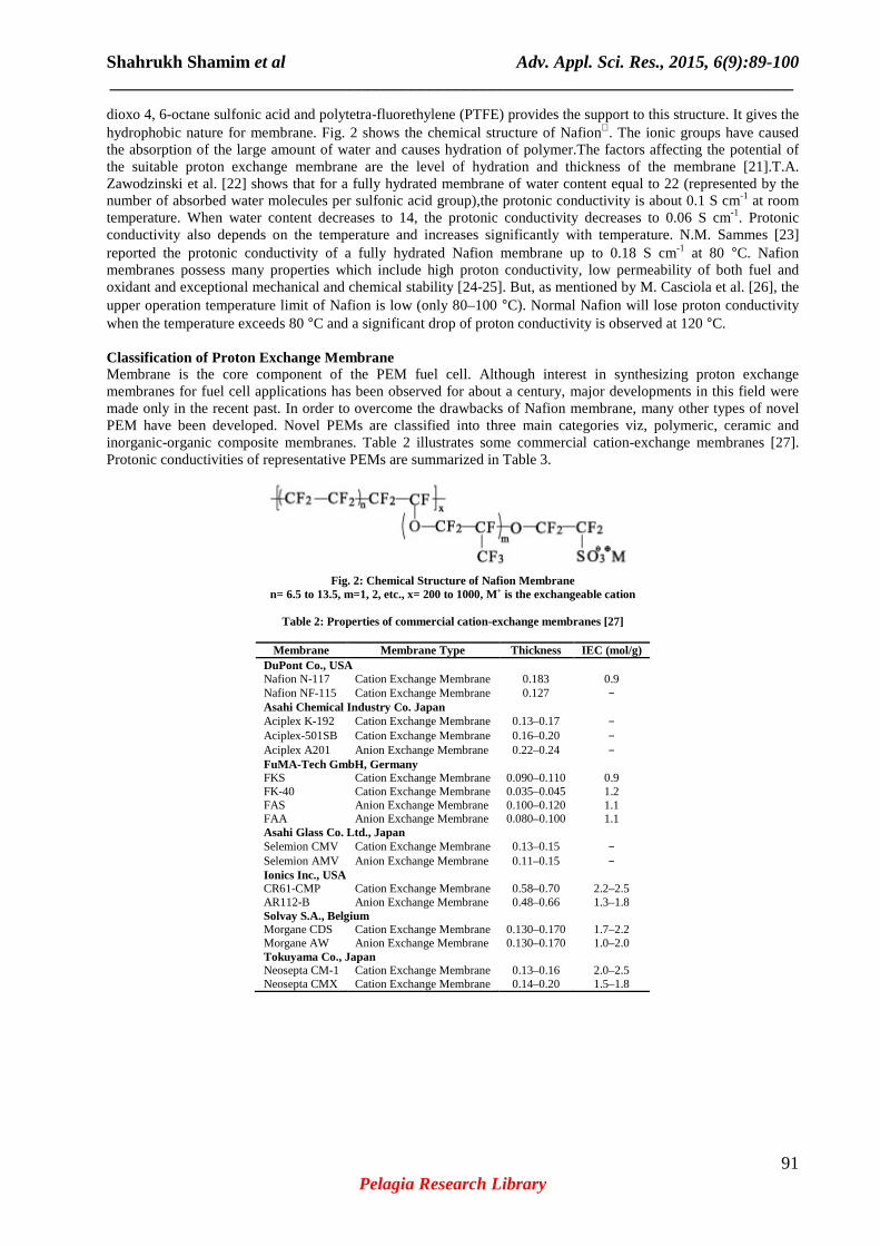
dioxo 4, 6-octane sulfonic acid and polytetra-fluorethylene (PTFE) provides the support to this structure. It gives the hydrophobic nature for membrane. Fig. 2 shows the chemical structure of Nafion. The ionic groups have caused the absorption of the large amount of water and causes hydration of polymer.The factors affecting the potential of the suitable proton exchange membrane are the level of hydration and thickness of the membrane [21].T.A. Zawodzinski et al. [22] shows that for a fully hydrated membrane of water content equal to 22 (represented by the number of absorbed water molecules per sulfonic acid group),the protonic conductivity is about 0.1 S cm-1 at room temperature. When water content decreases to 14, the protonic conductivity decreases to 0.06 S cm-1. Protonic conductivity also depends on the temperature and increases significantly with temperature. N.M. Sammes [23] reported the protonic conductivity of a fully hydrated Nafion membrane up to 0.18 S cm-1 at 80 °C. Nafion membranes possess many properties which include high proton conductivity, low permeability of both fuel and oxidant and exceptional mechanical and chemical stability [24-25]. But, as mentioned by M. Casciola et al. [26], the upper operation temperature limit of Nafion is low (only 80–100 °C). Normal Nafion will lose proton conductivity when the temperature exceeds 80 °C and a significant drop of proton conductivity is observed at 120 °C. Classification of Proton Exchange Membrane Membrane is the core component of the PEM fuel cell. Although interest in synthesizing proton exchange membranes for fuel cell applications has been observed for about a century, major developments in this field were made only in the recent past. In order to overcome the drawbacks of Nafion membrane, many other types of novel PEM have been developed. Novel PEMs are classified into three main categories viz, polymeric, ceramic and inorganic-organic composite membranes. Table 2 illustrates some commercial cation-exchange membranes [27]. Protonic conductivities of representative PEMs are summarized in Table 3.
Fig. 2: Chemical Structure of Nafion Membrane
n= 6.5 to 13.5, m=1, 2, etc., x= 200 to 1000, M+ is the exchangeable cation
Table 2: Properties of commercial cation-exchange membranes [27]
Shahrukh Shamim et al Adv. Appl. Sci. Res., 2015, 6(9):89-100 _____________________________________________________________________________
92 Pelagia Research Library
Table 3: Summary of Protonic conductivities of various PEMs
Proton Exchange Membrane Protonic Conductivity Nafion 0.13 S/cm at 75 °C and 100% relative humidity [28]; less than 0.01 s/cm at 20 °C [29] Modified Nafion (Hyflon) 0.013 s/cm at 20 °C [29] Hydrophilic–hydrophobic copolymer 0.09 s/cm at 30 °C and 100% relative humidity [30] Acid–base blends 0.046 s/cm at 165 °C [31] Side-modified hydrocarbons (SPEEK-based PEMs) Around 0.1 s/cm at 100 °C [32]
TiO2-based PEM 5.5x10⁻⁶ s/cm under normal ambient humidity environment (∼70%) [33] Nafion-inorganic solid acid composite conductivity can reach 0.1 s/cm at 90 °C and 0.02 s/cm at 120 °C [34] Ferroxane (carboxylate-FeOOH)-PVA composite
0.0025 s/cm at 100% RH and room temperature; lower than 10-5 s/cm at 33% RH and room temperature [35]
Polymeric PEM Most widely used membrane in fuel cells is Polymeric PEM. Proton-conductive groups like sulfonic acid are predominantly introduced to the main chain or side chains of the polymer. I order to obtain thermal and chemical stability the main chain of the polymer is often fluorinated. As discussed earlier, Nafion is the most widely used PEM in fuel cells. It is more desirable for proton conduction under elevated temperature and low humidity. There were extensive studies on the practicability to reform the properties of Nafion membrane. In order to increase thermal stability of Nafion, researchers modified the side chains of Nafion and produced a new perfluorinated membrane named Hyflon (Fig. 3) which possesses a higher ionic glass-transition temperature than Nafion, and enables operation at a higher temperature without impairing the membrane [29,36]. Furthermore, S.J. Paddison et al. [37] found that the number of –CF2 groups in the backbone of Hyflon influences the hydrogen bonding network of the water-sulfonic acid groups and leads to an increase in the number of water molecules required for functional proton transport.A. Roy et al. [38] have developed novel hydrophilic–hydrophobic perfluorinated block copolymers that provide enhanced proton transport, particularly at low relative humidity. The acid–base blend PEMs for fuel cell applications involves the addition of an acid component into an alkaline polymer, so as to encourage protonic conductivity [1]. These membranes are very stable in oxidizing or reducing environments and maintain relatively high conductivity at very high temperatures without significant dehydration effects [1]. Guo et al. [39] developed new acid–base blends that have a better performance than PBI/H3PO4. The membrane composed of a sulfonated poly (aryl ether ketone) (6FSPEEK) as an acidic component and an aminated poly (aryl ether ketone) with a naphthyl group (AmPEEKK-NA) as a basic component and this membrane attained a maximum protonic conductivity of 8.7 x
Fig. 3: Chemical Structure of Hyflon
10-2 S cm-1 at 80 °C, and is expected to increase at higher temperatures. Moreover, this membrane has high water uptake capacity and has an oxidative stability even higher than that of sulfonated polyether ether ketone membranes.Another type of acid–base blend PEM with SPEEK as an acid polymer and various amounts of polysulfone tethered with 5-aminobenzotriazole as a basic polymer was synthesized by Li et al. [40] for direct methanol fuel cell applications. Ceramic PEM Polymeric membranes play the dominant role in the PEM Fuel cell. But, over recent decade, Ceramic materials as possible proton exchange membranes for fuel cell applications have captivated the interest of researchers [41,42,43].The ceramic PEM can be classified into two main categories: (1) non-metal ceramic PEM and (2) hydrated metal oxide/oxyhydroxide ceramic PEM. The non-metal ceramic PEM, such as porous silica glass, has good chemical and mechanical stability, low material cost and endurance to high temperature. However,M. Nogami et al. [44] showed that the protonic conductivity of non-metal ceramic PEM tends to be much lower than Nafion (10-6 – 10-3 S cm-1 at 400–800 °C). Metal oxide ceramic membranes are mainly used in solid oxide fuel cells (SOFCs) and O2- ions are the main transfer ions in the membranes. For becoming a good candidate for PEMFCs, a metal oxide must have high water absorption capacity on its surface. Various metal oxides and metal oxyhydroxides have shown the capacity to conduct protons at different humidities, like TiO2, Al2O3, BaZrO3 and FeOOH [45, 41]. F.M. Vichi [42] reported the maximum protonic conductivities of TiO2 and Al2O3 are 1.1x10⁻³ S cm-1 at 97% RH and 5.5x10⁻⁴ S cm-1 at 81% RH, respectively, which are about one order of magnitude less than that of Nafion. As shown by E.M. Tsui et al. [46] the protonic conductivity of FeOOH is much higher than TiO2 and Al2O3 and even higher than that of Nafion.
Shahrukh Shamim et al Adv. Appl. Sci. Res., 2015, 6(9):89-100 _____________________________________________________________________________
93 Pelagia Research Library
The sol–gel process is the traditional approach to prepare ceramic thin films with nano-sized pores [41]. The most widely-used preparation method of FeOOH ceramics is to make coarse FeOOH particles (lepidocrocite) react with carboxylic acid to form nano-sized ferroxane (carboxylate-FeOOH) ceramics (Fig.4). The proton conductivity of the ferroxane ceramic membrane becomes low at low RHs, due to the presence of acetic acid groups. The existence of acetic acid groups hinders the transfer of protons among physisorbed water molecules. A sintering process is required to remove these acetic acid groups from the surface of the ceramic membrane. Sintering at 300 °C for several hours increases the protonic conductivity of the membrane [41]. The advantages of ceramic membranes include: excellent thermal and chemical stability, which enables the membrane to be used at high temperature, low material cost, and high proton conductivity [41]. Ferroxane ceramic membranes have both poor ductility and compression resistance. Due to the precursor of these membranes, lepidocrocite, which has very poor mechanical properties, the membranes are quite brittle and can be easily broken to very small pieces. The hardness of lepidocrocite is 5 GPa, which is very less than Al2O3 (20.6 GPa)and α-SiO2 (30.6 GPa) [47,48].
Fig. 4: Production Method of Ferroxane Membrane (modified from [41])
Solid acid PEM Solid Acid PEM is a promising class of materials for fuel cell membranes. The general formula for these materials is AxHy(XO4)(x+y)/2,where A = K, Rb, Cs, Tl, Li, or NH4and X = P, S, As or Se. Due to the phase transition in these materials, the proton conductivity increases by 2-3 orders of magnitude, reaching values as high as 10-1 S/cm. Hence they are called ‘‘superprotonic conductors’’. Solid acid PEM Fuel cell operate at medium temperatures (100-250 °C) since their superprotonic transition temperature is generally between 350 and 500 K (Table 4). This class of materials has been known for a long time by solid state physics due to their fascinating phase transitions. Many works have been done till now addressing the aspects like nature of the hydrogen bonding in the material and its effect on the macroscopic properties, e.g. on NaHSO4 [49], NH4HSeO4 [50], KHSO4 [51], TlHSO4 [52]. The superprotonic solid acids have been only recently considered for applications as fuel cell membranes, despite of their excellent proton transport properties. Haile SM et al. [53]showed the applicability of CsHSO4as fuel cell membrane material. Though, some technological challenges are remaining like processing of thin, impermeable solid-acid membranes, enhancement of electrode performance, and system design to protect the electrolyte from liquid water during fuel cell shut-off [53]. In addition to that, solid acids have some limitations like brittleness, water solubility and poor mechanical behaviour [54], and chemical instability [55]. Proton conduction in solid acid PEM is explained by two competing models [56].
Shahrukh Shamim et al Adv. Appl. Sci. Res., 2015, 6(9):89-100 _____________________________________________________________________________
94 Pelagia Research Library
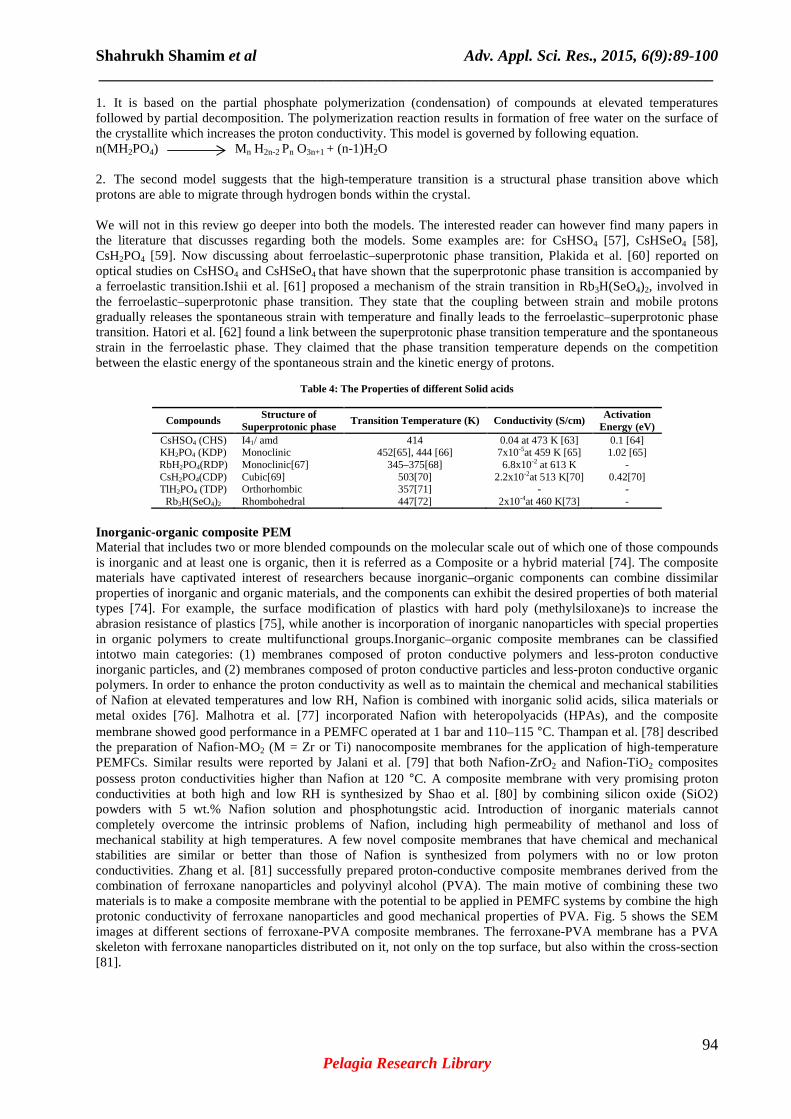
1. It is based on the partial phosphate polymerization (condensation) of compounds at elevated temperatures followed by partial decomposition. The polymerization reaction results in formation of free water on the surface of the crystallite which increases the proton conductivity. This model is governed by following equation. n(MH2PO4) Mn H2n-2 Pn O3n+1 + (n-1)H2O 2. The second model suggests that the high-temperature transition is a structural phase transition above which protons are able to migrate through hydrogen bonds within the crystal. We will not in this review go deeper into both the models. The interested reader can however find many papers in the literature that discusses regarding both the models. Some examples are: for CsHSO4 [57], CsHSeO4 [58], CsH2PO4 [59]. Now discussing about ferroelastic–superprotonic phase transition, Plakida et al. [60] reported on optical studies on CsHSO4 and CsHSeO4 that have shown that the superprotonic phase transition is accompanied by a ferroelastic transition.Ishii et al. [61] proposed a mechanism of the strain transition in Rb3H(SeO4)2, involved in the ferroelastic–superprotonic phase transition. They state that the coupling between strain and mobile protons gradually releases the spontaneous strain with temperature and finally leads to the ferroelastic–superprotonic phase transition. Hatori et al. [62] found a link between the superprotonic phase transition temperature and the spontaneous strain in the ferroelastic phase. They claimed that the phase transition temperature depends on the competition between the elastic energy of the spontaneous strain and the kinetic energy of protons.
Table 4: The Properties of different Solid acids
Compounds Structure of Superprotonic phase
Transition Temperature (K) Conductivity (S/cm) Activation Energy (eV)
Inorganic-organic composite PEM Material that includes two or more blended compounds on the molecular scale out of which one of those compounds is inorganic and at least one is organic, then it is referred as a Composite or a hybrid material [74]. The composite materials have captivated interest of researchers because inorganic–organic components can combine dissimilar properties of inorganic and organic materials, and the components can exhibit the desired properties of both material types [74]. For example, the surface modification of plastics with hard poly (methylsiloxane)s to increase the abrasion resistance of plastics [75], while another is incorporation of inorganic nanoparticles with special properties in organic polymers to create multifunctional groups.Inorganic–organic composite membranes can be classified intotwo main categories: (1) membranes composed of proton conductive polymers and less-proton conductive inorganic particles, and (2) membranes composed of proton conductive particles and less-proton conductive organic polymers. In order to enhance the proton conductivity as well as to maintain the chemical and mechanical stabilities of Nafion at elevated temperatures and low RH, Nafion is combined with inorganic solid acids, silica materials or metal oxides [76]. Malhotra et al. [77] incorporated Nafion with heteropolyacids (HPAs), and the composite membrane showed good performance in a PEMFC operated at 1 bar and 110–115 °C. Thampan et al. [78] described the preparation of Nafion-MO2 (M = Zr or Ti) nanocomposite membranes for the application of high-temperature PEMFCs. Similar results were reported by Jalani et al. [79] that both Nafion-ZrO2 and Nafion-TiO2 composites possess proton conductivities higher than Nafion at 120 °C. A composite membrane with very promising proton conductivities at both high and low RH is synthesized by Shao et al. [80] by combining silicon oxide (SiO2) powders with 5 wt.% Nafion solution and phosphotungstic acid. Introduction of inorganic materials cannot completely overcome the intrinsic problems of Nafion, including high permeability of methanol and loss of mechanical stability at high temperatures. A few novel composite membranes that have chemical and mechanical stabilities are similar or better than those of Nafion is synthesized from polymers with no or low proton conductivities. Zhang et al. [81] successfully prepared proton-conductive composite membranes derived from the combination of ferroxane nanoparticles and polyvinyl alcohol (PVA). The main motive of combining these two materials is to make a composite membrane with the potential to be applied in PEMFC systems by combine the high protonic conductivity of ferroxane nanoparticles and good mechanical properties of PVA. Fig. 5 shows the SEM images at different sections of ferroxane-PVA composite membranes. The ferroxane-PVA membrane has a PVA skeleton with ferroxane nanoparticles distributed on it, not only on the top surface, but also within the cross-section [81].
Shahrukh Shamim et al Adv. Appl. Sci. Res., 2015, 6(9):89-100 _____________________________________________________________________________
95 Pelagia Research Library
PEM FUEL CELL TECHNOLOGY: APPLICATIONS PEM fuel cells are being applied in the following three areas: transportation, stationary and portable power generation. The power of electric passenger car, utility vehicles, and bus ranges from 20 kW to 250 kW. The stationary power by general fuel cells has a wide range, 1–50 MW. Some small-scale stationary generation, e.g. for the remote telecommunication application, is 100–1 kW [82].
Fig. 5: SEM images of ferroxane-PVA composite, (a) surface of ferroxane-PVA composite membrane, (b) cross-sections of ferroxane-PVA composite membrane [81]
Transportation Among the many applications of PEMFCs, transportation is the most competitive and promising. Several concerns arise from the global, fast-growing vehicle market, such as air pollution, climate change (due to the greenhouse gases), and fuel sustainability. Most issues are associated with the conventional engines, i.e. ICEs (internal-combustion engines), which primarily depend on hydrocarbon fuels. PEM fuel cells have the potential to replace ICEs due to their potentials of achieving higher efficiency and lower GHG emissions. The typical power range for this type of applications, such as passenger cars, utility vehicles, and buses, ranges from 20 kW to 250 kW [82]. Fig. 6 shows the Transit vehicle Fuel types installed around the world in each category in 2010 [83]. McNicol et al. [84] reported that PEM fuel cells can be superior to ICEs in several aspects except the initial cost. Fig. 7 illustrates the manufacturing cost of Fuel cell in the year 2011 by Strategic Analysis Inc. [85]. Kazim [86] proposed a scheme with which the United Arab Emirates government can achieve greater economic and environmental benefits associated with the introduction of fuel-cell vehicles.
.
Fig. 6: Transit vehicle Fuel Types installedFig. 7: Manufacturing cost of Fuel cells in around the world in 2010 (modified from [84])2011 (modified from [85])
Light-weight Vehicles The production of regular automobiles increases steadily in early 2000s but becomes fluctuated in recent years. In the past few years, the fuel cell light-weight vehicle market has been led by Honda, General Motors, and others. Electric powered bicycles are commonly used on a daily basis for commuting in Taiwan and China. In 2004, Hwang et al. [87] published the test results of a prototype of electric bicycle powered by a PEMFC. According to the
10%
2%
8% 1%
16%63%
Diesel Electric LNG
Bio-Diesel Other
CNG Diesel
11%3%
18%
4%
3%
61%
Fuel Cell Stack Fuel Processor
Power Electronics Heat Exchanger
Assembly Balance of Plant
Shahrukh Shamim et al Adv. Appl. Sci. Res., 2015, 6(9):89-100 _____________________________________________________________________________
96 Pelagia Research Library
authors, the efficiency of the fuel-cell system reached up to 35%, which was significantly higher than that of an ICE, and a total of 6.8 g hydrogen covered the driving distance of 9.18 km, clearly demonstrating the distance-to-fuel ratio of 1.35 km/g. Meanwhile In 2007 General Motors, through its ‘‘Project Driveway” program, delivered over 100 units of its Chevrolet Equinox fuel-cell vehicles to California, Washington DC, and New York, which as of September 2009 had accumulated over 1,000,000 miles of driving [88]. Table 5 documents the key parameters of several fuel-cell vehicles.
Table 5: Specifications of several fuel-cell vehicles [89, 90]
Vehicle Name Type Year Power (kW) Hydrogen storage and capacity Driving Range Honda FCX-V3 Compact Car 2000 60 100 L at 250 atm 180 km Honda FCX-V4 Compact Car 2002 60 137 L at 350 atm 315 km Honda FCX 2nd Generation Compact Car 2004 80 156.6 L at 350 atm 430 km Honda FCX Clarity FCEV Compact Car 2007 100 3.92 kg at 5000 psi 240 miles Chevrolet HydroGen3 Minivan 2001 60 3.1 kg at 700 bar/4.6 kg at -253 °C 270 km/400 km Chevrolet Sequel Cross-over SUV 2005 73 8 kg at 700 bar 300 miles Chevrolet Equinox FCV Sport utility vehicle 2008 93 4.2 kg at 700 bar 200 mile Toyota FCHV Sport utility vehicle 2001 90 350 bar 180 miles Toyota FCHV-adv Sport utility vehicle 2009 90 156 L at 700 bar 430 miles Daimler B-Class Compact car 2009 100 700 bar 400 km
Buses Fig. 8 shows the number of fuel-cell buses commercialized each year from 1994 through 2008. In Fig. 8, the peak in 2003 corresponds to Daimler’s introduction of its 33-bus fleet for the European CUTE (Clean Urban Transport for Europe) and ECTOS (Ecological City Transport System) and Australian STEP (Sustainable Transport Energy Project) programs. In the CUTE program each participating city has different buses. Stockholm city runs the Mercedes-Benz Citaro fuel cell buses, which has two fuel cell stacks that produce a total power of 250 kW and capacity of 40 kg hydrogen stored at 350 bar that provides fuel for about 200 km operation [91]. At low power operation the fuel cell stack efficiency is over 65% based on the lower heat value. Due to the CUTE and similar programs, over half of the commercialized fuel-cell buses are running in Europe, a quarter in Asia, and 15% in North America.
Fig. 8: Number of Fuel Cell powered Buses manufactured (modified from [92])
Portable Application The fast-growing power demand by portable electronic devices is unlikely satisfied by current battery technology because of its low energy power capability and long charging time. These two issues can be well resolved by using portable/micro PEM fuel cells. The typical power range for portable electronic devices is 5–50 W and several developments focus on a level of <5 W for micro power application [93]. A wider range of power, 100–500 W, has also been considered[94]. Many researchers have advanced towards the fabrication of portable/micro fuel cell. Lee et al. [95] employed LIGA (which refers to the German acronym for X-ray lithography-technique: X-ray LIthographie, Galvanoformung (electro-deposition), and Abformtechnik (molding)) to fabricate flow channels in metallic bipolar plates. Ito et al. [96] utilized a technique similar to that used for machining of compact disks to create micro grooves in metal plates. Hahn et al. [97] used reactive ion etching (RIE) to machine microchannels in stainless steel plates. Hsieh et al. [98] proposed a SU-8 photoresist microfabrication process for the fuel cell flow structures. Cha et al. [99] employed various micro/nanofabrication processes, such as lithography, physical vapor
Shahrukh Shamim et al Adv. Appl. Sci. Res., 2015, 6(9):89-100 _____________________________________________________________________________
97 Pelagia Research Library
deposition (PVD), and focused ion beam (FIB) etch/deposition, to fabricate flow field plates.Madou et al. [100] used carbon obtained by pyrolyzing polymer precursors (called the ‘‘C-MEMS process) for the bipolar fluidic plates. Fig. 9 shows the peak power generated by bipolar fluidic plates.
Fig. 9: Peak Power generated as reported by various researchers
In addition to mobile phones and laptops, portable fuel cells can be used to power toys and utilities such as RC (radio control) cars, boats, robot toys, and emergency lights. Stationary Applications In general, due to priorbenefits of PEMFC, it is known that PEMFC technology is one of the more favourable candidates for a main or APU in the field of a stationary power plant. In 2005, Wang et al. [106] reported the development of the key components, specifications, configuration and operation characteristics of a 5 kW H2/air PEMFC system for a stationary power generator. It exhibits a quick start-up at room temperature (<1 min) and the efficiency of over 30%. Ladewig et al. [107] investigated another 5 kW stack system with 75 cells and 342 cm 2 active areas (supplied from Hélion Fuel Cell Company). It works with a natural gas reformer and hydrogen purification membrane unit. The DC output from the stack was converted to 240 V AC as output. The system was installed in Belfort, France with natural gas from the local supply. Hwang and Zou investigated the CHP efficiency and achieved a CHP efficiency of ∼81% [108]. It is worthy to note that there is competition from other types of fuel cells, notably MCFCs and SOFCs. Despite their low energy efficiency, MCFC or SOFC are currently believed to be one of the best technologies for stationary applications for reasons such as the use of a more available fuel such as methane than pure hydrogen [109]. Table 6 shows a list of companies working on the stationary applications.
Table 6: Several major fuel cell companies in the small stationary sector [110]
Company Location Details Altergy USA Fuel cell stacks and systems for the UPS market ClearEdge USA 5 kW CE5 natural gas fuelled CHP unit Ebara Ballard Japan JV between Ballard and Ebara, 1 kWe PEM system EneosCelltech Japan JV between Sanyo Electric and Nippon Oil P21 Germany Spin out from Vodaphone, supplies PEM UPS systems Matsushita Japan Delivered 650–1 kWe stacks
CONCLUSION
Today energy crises and environmental pollution has turned into a great problem for human. For solving these problems vast efforts to replace fossil fuels with other energy sources such as its connotation clean fuel have been taken. Fuel cells due to their particular properties are on the verge of creating a vast revolutionary change in the field of electricity. In the PEM fuel cells, from solid polymer electrolytes which have the ability to transfer of proton, has used as membrane. Ion exchange membranes especially proton exchange membrane, has an important role in the proton transferring in PEM fuel cells electrolyte. The desirable ion exchange membrane should be having the higher selectivity, suitable proton conductivity, good mechanical and chemical stability.Cation exchange membranes were obtained from the attachment of the acidic functional groups and the anion exchange membranes from the attachment of the alkaline functional groups into polymer backbone of membrane. The most important goals of modification of the proton exchange membranes in PEM fuel cells can be mentioned such as synthesis of the proton exchange membranes with lower cost compared to the other membranes (e.g. fluorinated). Based on a literature survey, this paper reviews the definition, principles and classification of potential materials used for the synthesis of
Shahrukh Shamim et al Adv. Appl. Sci. Res., 2015, 6(9):89-100 _____________________________________________________________________________
98 Pelagia Research Library
proton exchange membranes. The recent progress in development of proton exchange membranes that can work at high temperature and low relative humidity conditions is the main focus of this paper, and the categories of newly developed PEMs like polymeric PEM, ceramic PEM, Solid acid PEM and inorganic–organic composite PEM are discussed in detail. The review reveals that Nafion® is a more reliable membrane. Much research has been conducted on the details of the transport of protons through the polymer matrix and on novel methods of improving its properties but development of a sturdy inexpensive substitute to Nafion® is yet to materialize. SPEEK and acid–base blends show a great potential to substitute Nafion in high-temperature operating conditions, and although the synthesis processes are simple, the material costs must to be further reduced. For ceramic PEMs, poor ductility and compression resistance are the main obstacles for their application in commercial fuel cell systems. The durability of ceramic PEMs under prolonged fuel cell operation needs to be researched since under high moisture operation conditions the materials may disintegrate or dissolve. For the composite membranes with proton-conductive inorganic nanoparticles and organic polymers, Nafion-based composite PEMs have shown great potential to replace Nafion in high temperature and low RH operation conditions. As mentioned in the review, ferroxane sintered at 300 °C has a much higher protonic conductivity than the ferroxane green body. However, ferroxane-PVA composites cannot withstand high sintering temperatures. Therefore, polymers that can resist high temperatures, such as Teflon and PFA, may be used to prepare ferroxane-based composites. There are several issues to be solved before PEMFC can be properly commercialized like the stable and economical supply of high-purity hydrogen, existence of more efficient competitive power sources than the PEMFC system and the social viewpoints such as the health and environmental benefits as well as the infrastructural aspects of traditional power supply and demand. In conclusion, considering these issues, buses, portable, lightweight vehicles powered by PEMFC are the most promising applications. A PEMFC-based hybrid system should be used as the main substitution for traditional power sources in the near future due to their unique and relative advantages.
REFERENCES
[1] B.Smitha, S. Sridhar, A.A. Khan, J. Membr. Sci. 259 (2005) 10–26. [2] J. Zaidi, Polymer Membranes for Fuel Cells, Springer, New York, 2008. [3] N.M. Sammes, Springer, London, 2006 [4] Papageorgopoulos D. DOE fuel cell technology program overview and introduction to the 2010 fuel cell pre-solicitation workshop in DOE fuel cell pre-solicitation workshop. Department of Energy, Lakewood, Colorado; 2010 [5] Kwak, H.-Y., Lee, H.-S., Jung, J.-Y., Jeon, J.-S. and Park, D.-R., Fuel, Vol.83, No. 14-15, 2004, 2087-2094 [6] Baretto, L., Makihira, A., and Riahi, K., International Journal of Hydrogen Energy, Vol. 28, 2003, 267-284. [7] Midilli, A., Ay, M., Dincer, I. and Rosen, M.A., Renewable and Sustainable Energy Reviews Vol.9, No.3, 2005a, 291-307. [8] Hart, D., Journal of Power Sources, Vol. 86, 2000, 23-27. [9] Y. Wang et al., Applied Energy 88 (2011) 981–1007 [10] B.C.H. Steele, A. Heinzel, Materials for fuel-cell technologies, Nature 414 (2001) 345–352. [11] S. C. Singhal and K. Kendall, Elsevier, Oxford, UK, (2003) [12] S. C. Singhal, Solid State Ionics, 135, 305 (2000) [13] S. C. Singhal, Advances in Science and Technology, 45, 1837 (2006) [14] Mohammed ALHASSAN, Mohammed UMAR GARBA, Leonardo Electronic Journal of Practices and Technologies, Issue 9, July-December 2006, p. 99-106 [15] Hiroko Sotouchi and Akifusa Hagiwara, Energy Carriers and Conversion Systems- Vol. II [16] V. Verda, A. Sciacovelli, Applied Thermal Engineering, 31 (2011) pp. 2740-2748 [17] B. Gou, W.K. Na, B. Diong, CRC Press, Boca Raton, 2010 [18]Barbir F, Go´mez T., Int J Hydrogen Energy, 1996; 21: 891–901. [19]Costamagna P, Srinivasan S., J Power Sources 2001; 102: 242–52 [20] V. Guarau, F. Barbir, H. Liu, J. Electrochem. Soc., 147 (7) (2000) 2468 [21] Appleby AJ, Foulkes FR. Fuel cell handbook. New York: Van Nostrand Reinhold; 1989 [22] T.A. Zawodzinski, T.E. Springer, J. Davey, R. Jestel, C. Lopez, J. Valerio, S. Gottesfeld, J. Electrochem. Soc. 140 (1993) 1981–1985 [23] N.M. Sammes, Fuel Cell Technology: Reaching Towards Commercialization, Springer, London, 2006 [24] S. Motupally, A.J. Becker, J.W. Weidner, J. Electrochem. Soc. 147 (2000) 3171–3177. [25] S. Schlick, Ionomers: Characterization, Theory, and Applications, CRC Press, Boca Raton, 1996 [26] M. Casciola, G. Alberti, M. Sganappa, R. Narducci, J. Power Sources 162 (2006) 141–145. [27] T. Xu, Journal of Membrane Science 263 (2005) 1–29
Shahrukh Shamim et al Adv. Appl. Sci. Res., 2015, 6(9):89-100 _____________________________________________________________________________
99 Pelagia Research Library
[28] F. Bauer, S. Denneler, M. Willert-Porada, J. Polym. Sci. Pol. Phys. 43 (2005) 786–795. [29] L. Merlo, A. Ghielmi, L. Cirillo, M. Gebert, V. Arcella, Sep. Sci. Technol. 42 (2007) 2891–2908. [30] H. Ghassemi, J.E. McGrath, T.A. Zawodzinski, Polymer 47 (2006) 4132–4139. [31] Q.F. Li, H.A. Hjuler, N.J. Bjerrum, J. Appl. Electrochem. 31 (2001) 773–779 [32] J. Zaidi, Polymer Membranes for Fuel Cells, Springer, New York, 2008. [33] A. Thorne, A. Kruth, D. Tunstall, J.T.S. Irvine, W.Z. Zhou, J. Phys. Chem. B 109 (2005) 5439–5444 [34] N.H. Jalani, K. Dunn, R. Datta, Electrochim. Acta 51 (2005) 553–560. [35] S.-R.C. Liwei Zhang, Shihong Lin, Mark R. Wiesner, Environ. Eng. Sci. 29 (2012) 124–132. [36] V. Arcella, C. Troglia, A. Ghielmi, Ind. Eng. Chem. Res. 44 (2005) 7646–7651. [37] S.J. Paddison, J.A. Elliott, J. Phys. Chem. A 109 (2005) 7583–7593. [38] A. Roy, H.S. Lee, J.E. McGrath, Polymer 49 (2008) 5037–5044. [39] M.M. Guo, B.J. Liu, Z. Liu, L.F. Wang, Z.H. Jiang, J. Power Sources 189 (2009) 894–901 [40] W. Li, A. Manthiram, M.D. Guiver, J. Membr. Sci. 362 (2010) 289–297. [41] E.M. Tsui, M.M. Cortalezzi, M.R. Wiesner, J. Membr. Sci. 306 (2007) 8–15. [42] F.M. Vichi, M.T. Colomer, M.A. Anderson, Electrochemical Solid State Letter 2 (1999) 313–316. [43] F.M. Vichi, M.I. Tejedor-Tejedor, M.A. Anderson, Chem. Mater. 12 (2000) 1762–1770. [44] M. Nogami, R. Nagao, C. Wong, J. Phys. Chem. B 102 (1998) 5772–5775 [45] S.M. Haile, Acta Mater. 51 (2003) 5981–6000 [46] E.M. Tsui, M.R. Wiesner, J. Membr. Sci. 318 (2008) 79–83. [47] G. Kickelbick, Hybrid Materials: Synthesis, Characterization, and Applications, Wiley – VCH, Weinheim, 2007. [48] F.M. Gao, J.L. He, E.D. Wu, S.M. Liu, D.L. Yu, D.C. Li, S.Y. Zhang, Y.J. Tian, Phys. Rev. Lett. 91 (2003) [49] Zangmeister CD, Pemberton JE., J Solid State Chem2007;180(6):1826–31 [50] Lim AR, Jang SW, Chang JH., J PhysChem Solids 2008; 69(10):2360–5. [51] Yoshida Y, Matsuo Y, Ikehata S., Ferroelectrics 2004; 302:331–6 [52] Yoshida Y, Matsuo Y, Ikehata S., Ferroelectrics 2003; 285:487–92. [53] Haile SM, Boysen DA, Chisholm CRI, Merle RB, Nature 2001; 410(6831):910–3 [54] Boysen DA, Uda T, Chisholm CRI, Haile SM, Science 2004; 303(5654):68–70 [55] Baranov AI, Grebenev VV, Khodan AN, Dolbinina VV, Efremova EP, Solid State Ionics 2005; 176(39–40):2871–4. [56] Vijayakumar M, Bain AD, Goward GR., J PhysChem C 2009; 113(41):17950–7 [57] Ortiz E, Vargas RA, MellanderBE., J Phys – Condens Matter 2006; 18(42):9561–73 [58] Ortiz E, Trochez JC, Vargas RA., J Phys – Condense Matter, 2008; 20(36). [59] Park J-H., Phys Rev B 2004; 69(5):054104 [60]Plakida NM. Superionic, Phys Status Solidi B – Basic Res 1986; 135(1):133–9 [61] Ishii T., Solid State Ionics 2007; 178(7–10):667–70. [62] Hatori J, Matsuo Y, Ikehata S., Solid State Commun2006; 140(9–10):452–4 [63] Yang C, Costamagna P, Srinivasan S, Benziger J, Bocarsly AB., J Power Sources 2001; 03(1):1–9 [64] Belushkin AV, Carlile CJ, Shuvalov LA., J PhysCondens Matter 1992; 4:389–98 [65] Chen RH, Yen CC, Shern CS, Fukami T., Solid State Ionics 2006; 177(33–34):2857–64 [66] Baranov AI, Khiznichenko VP, Shuvalov LA., Ferroelectrics 1989; 100:135–41 [67] Kumukae M, Kawashima K, Osaka T., J PhysSocJpn 2000; 69:2076–81. [68] hapira Y, Levin S, Gerlich D, Szapiro S., Ferroelectrics 1978; 17(3–4):459–64 [69] Botez CE, Hermosillo JD, Zhang JZ, Qian J, Zhao YS, J Chem Phys 2007; 127(19) [70] Haile SM, Chisholm CRI, Sasaki K, Boysen DA, Uda T., Faraday Discuss 2007; 134:17–39 [71]Hanazawa K, Komukae M, Okasa T, Makita Y, Arai M, Yagi T, et al., J PhysSocJpn 1991;60: 188–95 [72] Plakida NM, Salejda W.,Phys Status Solidi B – Basic Res 1988; 148(2):473–81. [73] Pawlowski A, Polomska M, Hilczer B, Szczesniak L, Pietraszko A., J Power Sources 2007; 173(2):781–7 [74] G. Kickelbick, Hybrid Materials: Synthesis, Characterization, and Applications, Wiley – VCH, Weinheim, 2007 [75] G. Schottner, Chem. Mater. 13 (2001) 3422–3435 [76] J. Zaidi, Polymer Membranes for Fuel Cells, Springer, New York, 2008. [77] S. Malhotra, R. Datta, J. Electrochem. Soc. 144 (1997) L23–L26. [78] T.M. Thampan, N.H. Jalani, P. Choi, R. Datta, J. Electrochem. Soc. 152 (2005) A316– A325. [79] N.H. Jalani, K. Dunn, R. Datta, Electrochim. Acta 51 (2005) 553–560 [80] Z.G. Shao, P. Joghee, I.M. Hsing, J. Membr. Sci. 229 (2004) 43–51. [81] S.-R.C. Liwei Zhang, Shihong Lin, Mark R. Wiesner, Environ. Eng. Sci. 29 (2012) 124–132 [82] Lipman T, Sperling D. Market concepts, competing technologies and cost challenges for automotive and stationary applications. In: Vielstich W, Gasteiger H, Lamm A, editors. Handbook of fuel cells: fundamentals, technology and applications. John Wiley & Sons Ltd.; 2003. p. 1318–28.
Shahrukh Shamim et al Adv. Appl. Sci. Res., 2015, 6(9):89-100 _____________________________________________________________________________
100 Pelagia Research Library
[83] The Path to Commercial Fuel Cell Buses: Applying Lessons from History, Hosted by National Fuel Cell Bus Program, Sponsored by Ballard. [84]McNicol BD, Rand DAJ, Williams KR., J Power Sources 2001;100(1–2):47–59 [85] B.D. James, J. Perez, K.N. Baum, A. Spisak, M. Sanders, Presentation at the Fuel Cell Seminar & Exposition, Orlando, FL, 2011. [86]Kazim A., Appl Energy 2003; 74(1–2):125–33. [87] Hwang JJ, Wang DY, Shih NC, Lai DY, Chen CK., J Power Sources 2004; 133:223–8. [88] Vann M. Chevrolet project driveway fuel cell program passes 1 million miles this week. GM fastlane blog; 2009 http://fastlane.gmblogs.com/archives/2009/09/chevrolet_project_driveway_fuel_cell_program_passes_1_million_miles_this_week.html [02.12.09] [89] Honda. Honda fuel cell power FCX; December 2004. http://world.honda. com/FuelCell/FCX/FCXPK.pdf. [02.12.2010] [90] Fuel cell vehicles (from Auto Manufacturers), Fuel cells;2000. <http://www.fuelcells.org/info/charts/carchart.pdf> [91] Haraldsson K, Folkesson A, Alvfors P., J Power Sources 2005;145(2):620–31. [92] Jerram LC., 2008 Bus survey, Fuel Cell Today 2008. [93] Lipman T, Sperling D. Market concepts, competing technologies and cost challenges for automotive and stationary applications. In: Vielstich W, Gasteiger H, Lamm A, editors. Handbook of fuel cells: fundamentals, technology and applications, John Wiley & Sons, Ltd.; 2003. p. 1318–28 [94] Narayanan SR, Valdez TI, Rohatgi N. Portable direct methanol fuel cell system. In: Vielstich W, Gasteiger HA, Lamm A, editor, Handbook of fuel cells, John Wiley and Sons; 2003. [95] Lee S-J, Chen Y-P, Huang C-H, J Power Sources 2005; 145(2):369–75. [96] Ito T, Kaneko S, Kunimatsu M.,Electrochem Solid-State Lett2009; 12(11):B154–7. [97] Hahn R et al., J Power Sources 2004; 131(1–2):73–8. [98] Hsieh SS et al., J Solid State Electrochem 2005; 9:121–31. [99] Cha SW et al., J Power Sources 2004; 134(1):57–71. [100] Park BY, MadouMJ., J Power Sources 2006; 162(1):369–79. [101] SiewHwa C et al., J Micromech Microeng 2005; 15(1):231. [102] Müller M et al.,MicrosystTechnol 2003; 9(3):159–62. [103] Hsieh SS et al., J Solid StateElectrochem, 2005; 9:121–31 [104] Heinzel A et al., J Power Sources 2002; 105(2):250–5. [105] Wang Y et al., J Power Sources 2010. [106] Wang C, Mao Z, Bao F, Li X, Xie X.,Int J Hydrogen Energy 2005; 30:1031–4. [107] Ladewig BP, Lapicque F., Fuel Cells 2009; 9(2):157–63. [108] Hwang JJ, Zou ML, J Power Sources 2010; 195(9):2579–85 [109]Cacciola G, Antonucci V, Freni S., J Power Sources 2001; 100:67–79. [110] Adamson K-A, Fuel Cell Today 2009:11–2.