58
Avalon Interface Specifications Subscribe Send Feedback MNL- AVABUSREF 2015.03.04 101 Innovation Drive San Jose, CA 95134 www.altera.com

Avalon Interface Specifications
Subscribe
Send Feedback
MNL-AVABUSREF
2015.03.04
101 Innovation DriveSan Jose, CA 95134www.altera.com

Contents
1. Introduction to the Avalon Interface Specifications...................................... 1-11.1 Avalon Properties and Parameters......................................................................................................1-41.2 Signal Roles ............................................................................................................................................1-41.3 Interface Timing ................................................................................................................................... 1-41.4 Related Documents ...............................................................................................................................1-4
2. Avalon Clock and Reset Interfaces .................................................................2-12.1 Avalon Clock Sink Signal Roles .......................................................................................................... 2-12.2 Clock Sink Properties ...........................................................................................................................2-22.3 Associated Clock Interfaces .................................................................................................................2-22.4 Avalon Clock Source Signal Roles ......................................................................................................2-22.5 Clock Source Properties........................................................................................................................2-32.6 Reset Sink ...............................................................................................................................................2-32.7 Reset Sink Interface Properties............................................................................................................ 2-32.8 Associated Reset Interfaces ..................................................................................................................2-42.9 Reset Source ...........................................................................................................................................2-42.10 Reset Source Interface Properties......................................................................................................2-4
3. Avalon Memory-Mapped Interfaces............................................................... 3-13.1 Introduction to Avalon Memory-Mapped Interfaces ..................................................................... 3-13.2 Avalon Memory-Mapped Interface Signal Roles.............................................................................. 3-33.3 Interface Properties .............................................................................................................................. 3-83.4 Timing ..................................................................................................................................................3-113.5 Transfers .............................................................................................................................................. 3-11
3.5.1 Typical Read and Write Transfers .....................................................................................3-123.5.2 Read and Write Transfers with Fixed Wait-States ..........................................................3-133.5.3 Pipelined Transfers ..............................................................................................................3-143.5.4 Burst Transfers .....................................................................................................................3-16
3.6 Address Alignment .............................................................................................................................3-193.7 Avalon-MM Slave Addressing ..........................................................................................................3-19
4. Avalon Interrupt Interfaces ............................................................................4-14.1 Interrupt Sender ....................................................................................................................................4-1
4.1.1 Avalon Interrupt Sender Signal Roles .................................................................................4-14.1.2 Interrupt Sender Properties ..................................................................................................4-1
4.2 Interrupt Receiver .................................................................................................................................4-24.2.1 Avalon Interrupt Receiver Signal Roles ..............................................................................4-24.2.2 Interrupt Receiver Properties ...............................................................................................4-24.2.3 Interrupt Timing ....................................................................................................................4-3
TOC-2
Altera Corporation
5. Avalon Streaming Interfaces .......................................................................... 5-15.1 Terms and Concepts .............................................................................................................................5-25.2 Avalon Streaming Interface Signal Roles .......................................................................................... 5-35.3 Signal Sequencing and Timing ........................................................................................................... 5-4
5.3.1 Synchronous Interface .......................................................................................................... 5-45.3.2 Clock Enables ......................................................................................................................... 5-4
5.4 Avalon-ST Interface Properties .......................................................................................................... 5-45.5 Typical Data Transfers ......................................................................................................................... 5-55.6 Signal Details ......................................................................................................................................... 5-65.7 Data Layout ............................................................................................................................................5-65.8 Data Transfer without Backpressure ..................................................................................................5-75.9 Data Transfer with Backpressure ....................................................................................................... 5-75.10 Packet Data Transfers ........................................................................................................................ 5-95.11 Signal Details ..................................................................................................................................... 5-105.12 Protocol Details .................................................................................................................................5-10
6. Avalon Conduit Interfaces ............................................................................. 6-16.1 Avalon Conduit Signal Roles .............................................................................................................. 6-26.2 Conduit Properties ............................................................................................................................... 6-2
7. Avalon Tristate Conduit Interface ................................................................. 7-17.1 Avalon Tristate Conduit Signal Roles ................................................................................................7-37.2 Tristate Conduit Properties .................................................................................................................7-47.3 Tristate Conduit Timing ......................................................................................................................7-4
A. Deprecated Signals.........................................................................................A-1
B. Additional Information................................................................................. B-1B.1 How to Contact Altera......................................................................................................................... B-2B.2 Typographic Conventions................................................................................................................... B-3
TOC-3
Altera Corporation

Introduction to the Avalon InterfaceSpecifications 1
2015.03.04
MNL-AVABUSREF Subscribe Send Feedback
Avalon® interfaces simplify system design by allowing you to easily connect components in an Altera®
FPGA. The Avalon interface family defines interfaces appropriate for streaming high-speed data, readingand writing registers and memory, and controlling off-chip devices. These standard interfaces aredesigned into the components available in Qsys. You can also use these standardized interfaces in yourcustom components. By using these standard interfaces, you enhance the interoperability of your designs.
This specification defines all of the Avalon interfaces. After reading it, you should understand whichinterfaces are appropriate for your components and which signal roles to use for particular behaviors.This specification defines the following seven interfaces:
• Avalon Streaming Interface (Avalon-ST)—an interface that supports the unidirectional flow of data,including multiplexed streams, packets, and DSP data.
• Avalon Memory Mapped Interface (Avalon-MM)—an address-based read/write interface typical ofmaster–slave connections.
• Avalon Conduit Interface— an interface type that accommodates individual signals or groups ofsignals that do not fit into any of the other Avalon types. You can connect conduit interfaces inside aQsys system. Or, you can export them to make connections to other modules in the design or to FPGApins.
• Avalon Tri-State Conduit Interface (Avalon-TC) —an interface to support connections to off-chipperipherals. Multiple peripherals can share pins through signal multiplexing, reducing the pin count ofthe FPGA and the number of traces on the PCB.
• Avalon Interrupt Interface—an interface that allows components to signal events to other components.• Avalon Clock Interface—an interface that drives or receives clocks.• Avalon Reset Interface—an interface that provides reset connectivity.
A single component can include any number of these interfaces and can also include multiple instances ofthe same interface type. For example, in the first figure below, the Ethernet Controller includes thefollowing six different interface types:
• Avalon-MM• Avalon-ST• Avalon Conduit• Avalon-TC• Avalon Interrupt• Avalon Clock.
© 2015 Altera Corporation. All rights reserved. ALTERA, ARRIA, CYCLONE, ENPIRION, MAX, MEGACORE, NIOS, QUARTUS and STRATIX words and logos aretrademarks of Altera Corporation and registered in the U.S. Patent and Trademark Office and in other countries. All other words and logos identified astrademarks or service marks are the property of their respective holders as described at www.altera.com/common/legal.html. Altera warrants performanceof its semiconductor products to current specifications in accordance with Altera's standard warranty, but reserves the right to make changes to anyproducts and services at any time without notice. Altera assumes no responsibility or liability arising out of the application or use of any information,product, or service described herein except as expressly agreed to in writing by Altera. Altera customers are advised to obtain the latest version of devicespecifications before relying on any published information and before placing orders for products or services.
ISO9001:2008Registered
www.altera.com101 Innovation Drive, San Jose, CA 95134
Note: Avalon interfaces are an open standard. No license or royalty is required to develop and sellproducts that use, or are based on Avalon interfaces.
The following figures illustrate the use of the Avalon interfaces in system designs.
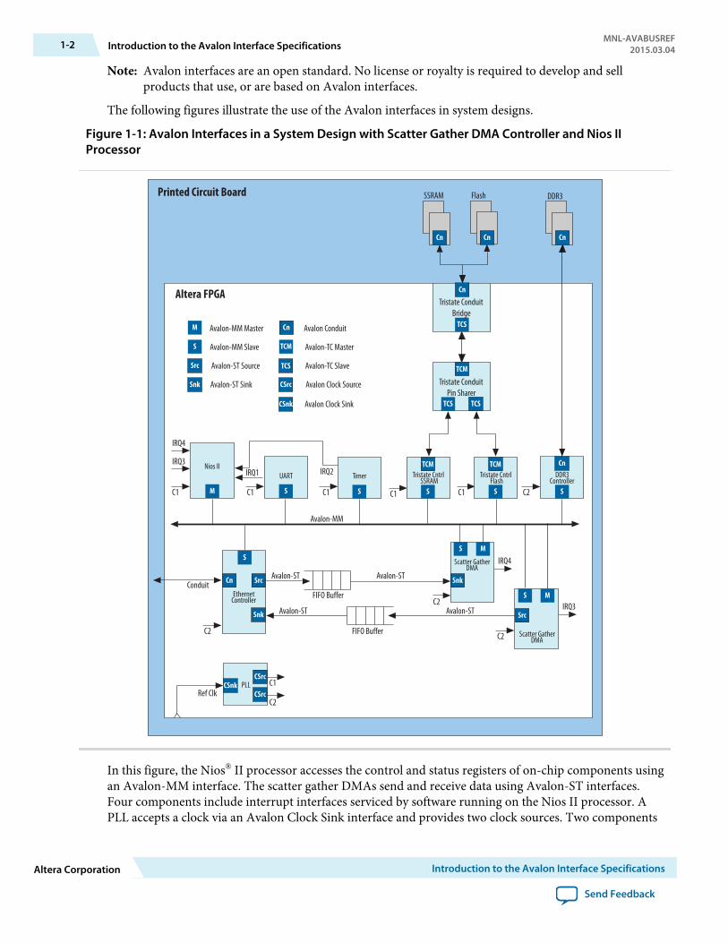
Figure 1-1: Avalon Interfaces in a System Design with Scatter Gather DMA Controller and Nios IIProcessor
IRQ1 IRQ2
C1
Conduit
Avalon-MM
C2
Avalon-ST
C1C1
Avalon-ST
FIFO Buffer
FIFO Buffer
Avalon-ST Avalon-ST
C2
C2C2
C1
C2Ref Clk
FlashSSRAM DDR3
Altera FPGA
Printed Circuit Board
IRQ3
IRQ4
IRQ3
IRQ4
TimerUARTNios II
C1C1
Tristate Cntrl SSRAM
PLL
TCM
TCM
TCSTCS
M S
S
S S
MS
MS
TCM
S S
Cn
Cn
Cn
CSnkCSrc
CSrc
CSnk
CSrc
Src
SrcSnk
Snk
Avalon-MM Master
Avalon-MM Slave
Avalon-ST Source
Avalon Conduit
Avalon-TC Master
Avalon-TC Slave
Avalon Clock Source
Avalon Clock Sink
Avalon-ST Sink
TCS
TCM
M
S
Cn
Src
Snk
Cn Cn Cn
TCS
Tristate Cntrl Flash
DDR3Controller
Scatter GatherDMA
Scatter GatherDMA
EthernetController
Tristate ConduitBridge
Tristate ConduitPin Sharer
In this figure, the Nios® II processor accesses the control and status registers of on-chip components usingan Avalon-MM interface. The scatter gather DMAs send and receive data using Avalon-ST interfaces.Four components include interrupt interfaces serviced by software running on the Nios II processor. APLL accepts a clock via an Avalon Clock Sink interface and provides two clock sources. Two components
1-2 Introduction to the Avalon Interface SpecificationsMNL-AVABUSREF
2015.03.04
Altera Corporation Introduction to the Avalon Interface Specifications
Send Feedback

include Avalon-TC interfaces to access off-chip memories. Finally, the DDR3 controller accesses externalDDR3 memory using an Avalon Conduit interface.
Figure 1-2: Avalon Interfaces in a System Design with PCI Express Endpoint and External Processor
Avalon-MM
C1C1
C1
C2Ref Clk
Altera FPGA
Printed Circuit Board
IRQ1 IRQ2 IRQ3
C1
CustomLogic
EthernetMAC
PLL
M M
S
Cn
CSnkCSrc
CSrc
SDRAMController
IRQ4
C2
IRQ5
C2
FlashSSRAM
C1
TCS
TCM TCM
TCS TCS
Cn
TCM
S
UART
S
CustomLogic
SDRAM
CnCn Cn
SS
Tristate Cntrl SSRAM
Tristate Cntrl Flash
Tristate ConduitPin Sharer
Tristate ConduitBridge
C1
PCI ExpressEndpoint
MIRQ1IRQ2IRQ3IRQ4IRQ5
External BusProtocol
Bridge
M
PCI ExpressRoot Port
ExternalCPU
In the previous figure, an external processor accesses the control and status registers of on-chipcomponents via an external bus bridge with an Avalon-MM interface. The PCI Express Root Port controlsdevices on the printed circuit board and the other components of the FPGA by driving an on-chip PCIExpress Endpoint with an Avalon-MM master interface. An external processor handles interrupts fromfive components. A PLL accepts a reference clock via a Avalon Clock sink interface and provides twoclock sources. The flash and SRAM memories use an Avalon-TC interface to share FPGA pins. Finally, anSDRAM controller accesses an external SDRAM memory using an Avalon Conduit interface.
MNL-AVABUSREF2015.03.04 Introduction to the Avalon Interface Specifications 1-3
Introduction to the Avalon Interface Specifications Altera Corporation
Send Feedback
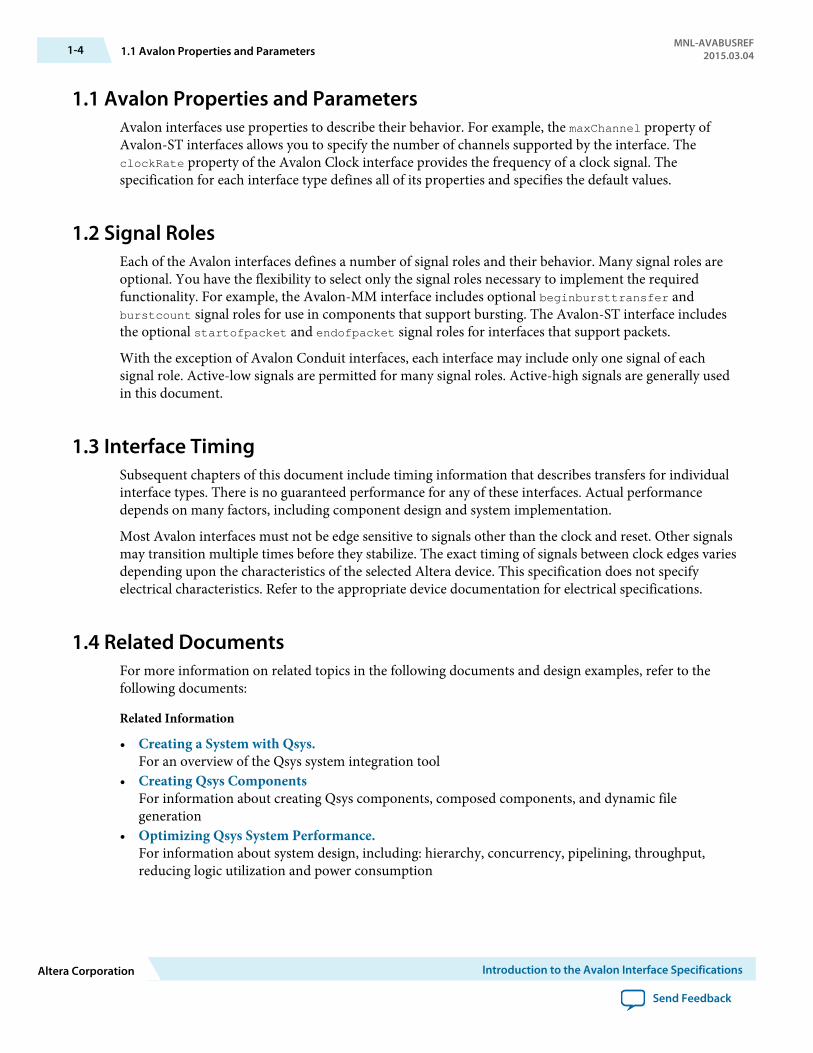
1.1 Avalon Properties and ParametersAvalon interfaces use properties to describe their behavior. For example, the maxChannel property ofAvalon-ST interfaces allows you to specify the number of channels supported by the interface. TheclockRate property of the Avalon Clock interface provides the frequency of a clock signal. Thespecification for each interface type defines all of its properties and specifies the default values.
1.2 Signal RolesEach of the Avalon interfaces defines a number of signal roles and their behavior. Many signal roles areoptional. You have the flexibility to select only the signal roles necessary to implement the requiredfunctionality. For example, the Avalon-MM interface includes optional beginbursttransfer andburstcount signal roles for use in components that support bursting. The Avalon-ST interface includesthe optional startofpacket and endofpacket signal roles for interfaces that support packets.
With the exception of Avalon Conduit interfaces, each interface may include only one signal of eachsignal role. Active-low signals are permitted for many signal roles. Active-high signals are generally usedin this document.
1.3 Interface TimingSubsequent chapters of this document include timing information that describes transfers for individualinterface types. There is no guaranteed performance for any of these interfaces. Actual performancedepends on many factors, including component design and system implementation.
Most Avalon interfaces must not be edge sensitive to signals other than the clock and reset. Other signalsmay transition multiple times before they stabilize. The exact timing of signals between clock edges variesdepending upon the characteristics of the selected Altera device. This specification does not specifyelectrical characteristics. Refer to the appropriate device documentation for electrical specifications.
1.4 Related DocumentsFor more information on related topics in the following documents and design examples, refer to thefollowing documents:
Related Information
• Creating a System with Qsys.For an overview of the Qsys system integration tool
• Creating Qsys ComponentsFor information about creating Qsys components, composed components, and dynamic filegeneration
• Optimizing Qsys System Performance.For information about system design, including: hierarchy, concurrency, pipelining, throughput,reducing logic utilization and power consumption
1-4 1.1 Avalon Properties and ParametersMNL-AVABUSREF
2015.03.04
Altera Corporation Introduction to the Avalon Interface Specifications
Send Feedback

• Component Interface Tcl ReferenceFor information about defining Qsys components and a reference for component Tool CommandLanguage (Tcl)
• Qsys System Design ComponentsFor information about system design components available in the IP Catalog
• Qsys Tutorial Design ExampleFor tutorial that shows how to build a memory test system using components with Avalon interfaces
MNL-AVABUSREF2015.03.04 1.4 Related Documents 1-5
Introduction to the Avalon Interface Specifications Altera Corporation
Send Feedback

Avalon Clock and Reset Interfaces 22015.03.04
MNL-AVABUSREF Subscribe Send Feedback
Avalon Clock interfaces define the clock or clocks used by a component. Components can have clockinputs, clock outputs, or both. A phase locked loop (PLL) is an example of a component that has both aclock input and clock outputs.
The following figure is a simplified illustration showing the most important inputs and outputs of a PLLcomponent.
Figure 2-1: PLL Core Clock Outputs and Inputs
PLL Core
altpll Megafunction
ref_clk
Clock Output Interface1
Clock Output Interface2
Clock Output Interface_n
reset
ClockSink
ClockSource
ClockSource
ClockSource
ResetSink
2.1 Avalon Clock Sink Signal RolesA clock sink provides a timing reference for other interfaces and internal logic.
Table 2-1: Clock Sink Signal Roles
Signal Role Width Direction Required Description
clk 1 Input Yes A clock signal. Provides synchronization forinternal logic and for other interfaces.
© 2015 Altera Corporation. All rights reserved. ALTERA, ARRIA, CYCLONE, ENPIRION, MAX, MEGACORE, NIOS, QUARTUS and STRATIX words and logos aretrademarks of Altera Corporation and registered in the U.S. Patent and Trademark Office and in other countries. All other words and logos identified astrademarks or service marks are the property of their respective holders as described at www.altera.com/common/legal.html. Altera warrants performanceof its semiconductor products to current specifications in accordance with Altera's standard warranty, but reserves the right to make changes to anyproducts and services at any time without notice. Altera assumes no responsibility or liability arising out of the application or use of any information,product, or service described herein except as expressly agreed to in writing by Altera. Altera customers are advised to obtain the latest version of devicespecifications before relying on any published information and before placing orders for products or services.
ISO9001:2008Registered
www.altera.com101 Innovation Drive, San Jose, CA 95134
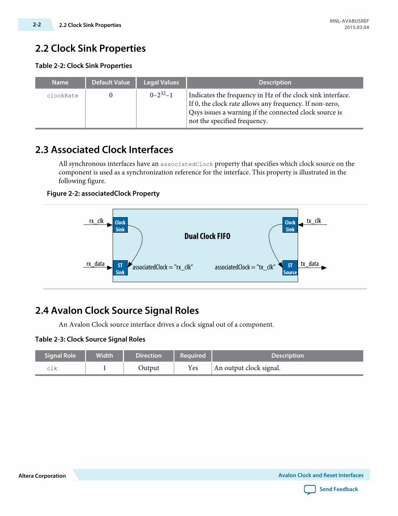
2.2 Clock Sink Properties
Table 2-2: Clock Sink Properties
Name Default Value Legal Values Description
clockRate 0 0–232–1 Indicates the frequency in Hz of the clock sink interface.If 0, the clock rate allows any frequency. If non-zero,Qsys issues a warning if the connected clock source isnot the specified frequency.
2.3 Associated Clock InterfacesAll synchronous interfaces have an associatedClock property that specifies which clock source on thecomponent is used as a synchronization reference for the interface. This property is illustrated in thefollowing figure.
Figure 2-2: associatedClock Property
Dual Clock FIFO
rx_clk
STSink
ClockSink
tx_clk
STSource
associatedClock = "rx_clk" associatedClock = "tx_clk"
ClockSink
rx_data tx_data
2.4 Avalon Clock Source Signal RolesAn Avalon Clock source interface drives a clock signal out of a component.
Table 2-3: Clock Source Signal Roles
Signal Role Width Direction Required Description
clk 1 Output Yes An output clock signal.
2-2 2.2 Clock Sink PropertiesMNL-AVABUSREF
2015.03.04
Altera Corporation Avalon Clock and Reset Interfaces
Send Feedback
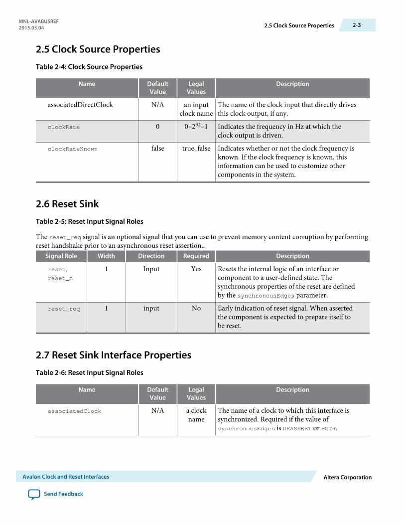
2.5 Clock Source Properties
Table 2-4: Clock Source Properties
Name DefaultValue
LegalValues
Description
associatedDirectClock N/A an inputclock name
The name of the clock input that directly drivesthis clock output, if any.
clockRate 0 0–232–1 Indicates the frequency in Hz at which theclock output is driven.
clockRateKnown false true, false Indicates whether or not the clock frequency isknown. If the clock frequency is known, thisinformation can be used to customize othercomponents in the system.
2.6 Reset Sink
Table 2-5: Reset Input Signal Roles
The reset_req signal is an optional signal that you can use to prevent memory content corruption by performingreset handshake prior to an asynchronous reset assertion..
Signal Role Width Direction Required Description
reset,
reset_n
1 Input Yes Resets the internal logic of an interface orcomponent to a user-defined state. Thesynchronous properties of the reset are definedby the synchronousEdges parameter.
reset_req 1 input No Early indication of reset signal. When assertedthe component is expected to prepare itself tobe reset.
2.7 Reset Sink Interface Properties
Table 2-6: Reset Input Signal Roles
Name DefaultValue
LegalValues
Description
associatedClock N/A a clockname
The name of a clock to which this interface issynchronized. Required if the value ofsynchronousEdges is DEASSERT or BOTH.
MNL-AVABUSREF2015.03.04 2.5 Clock Source Properties 2-3
Avalon Clock and Reset Interfaces Altera Corporation
Send Feedback
Name DefaultValue
LegalValues
Description
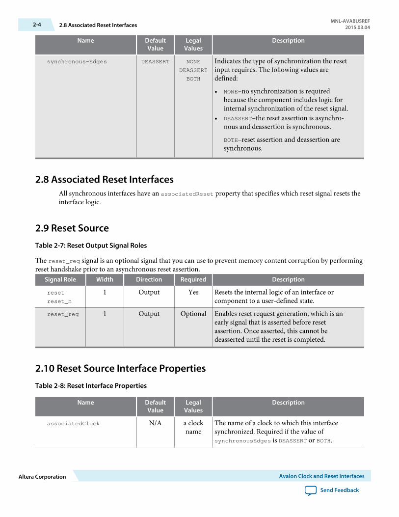
synchronous-Edges DEASSERT NONE
DEASSERT
BOTH
Indicates the type of synchronization the resetinput requires. The following values aredefined:
• NONE–no synchronization is requiredbecause the component includes logic forinternal synchronization of the reset signal.
• DEASSERT–the reset assertion is asynchro‐nous and deassertion is synchronous.
BOTH–reset assertion and deassertion aresynchronous.
2.8 Associated Reset InterfacesAll synchronous interfaces have an associatedReset property that specifies which reset signal resets theinterface logic.
2.9 Reset Source
Table 2-7: Reset Output Signal Roles
The reset_req signal is an optional signal that you can use to prevent memory content corruption by performingreset handshake prior to an asynchronous reset assertion.
Signal Role Width Direction Required Description
reset
reset_n
1 Output Yes Resets the internal logic of an interface orcomponent to a user-defined state.
reset_req 1 Output Optional Enables reset request generation, which is anearly signal that is asserted before resetassertion. Once asserted, this cannot bedeasserted until the reset is completed.
2.10 Reset Source Interface Properties
Table 2-8: Reset Interface Properties
Name DefaultValue
LegalValues
Description
associatedClock N/A a clockname
The name of a clock to which this interfacesynchronized. Required if the value ofsynchronousEdges is DEASSERT or BOTH.
2-4 2.8 Associated Reset InterfacesMNL-AVABUSREF
2015.03.04
Altera Corporation Avalon Clock and Reset Interfaces
Send Feedback

Name DefaultValue
LegalValues
Description
associatedDirectReset N/A a resetname
The name of the reset input that directly drivesthis reset source through a one-to-one link.
associatedResetSinks N/A a resetname
Specifies reset inputs which will eventuallycause a reset source to assert reset. For example,a reset synchronizer ORs a number of resetinputs to generate a reset output.
synchronousEdges DEASSERT NONE
DEASSERT
BOTH
Indicates the reset output's synchronization.The following values are defined:
• NONE–The reset interface is asynchronous.• DEASSERT–the reset assertion is asynchro‐
nous and deassertion is synchronous.• BOTH–reset assertion and deassertion are
synchronous.
MNL-AVABUSREF2015.03.04 2.10 Reset Source Interface Properties 2-5
Avalon Clock and Reset Interfaces Altera Corporation
Send Feedback

Avalon Memory-Mapped Interfaces 32015.03.04
MNL-AVABUSREF Subscribe Send Feedback
3.1 Introduction to Avalon Memory-Mapped InterfacesYou can use Avalon Memory-Mapped (Avalon-MM) interfaces to implement read and write interfacesfor master and slave components. The following are examples of component that typically includememory-mapped interfaces:
• Microprocessors• Memories• UARTs• DMAs• Timers
Avalon-MM interfaces range from simple to complex. For example, SRAM interfaces that have fixed-cycleread and write transfers have simple Avalon-MM interfaces. Pipelined interfaces capable of burst transfersare complex.
© 2015 Altera Corporation. All rights reserved. ALTERA, ARRIA, CYCLONE, ENPIRION, MAX, MEGACORE, NIOS, QUARTUS and STRATIX words and logos aretrademarks of Altera Corporation and registered in the U.S. Patent and Trademark Office and in other countries. All other words and logos identified astrademarks or service marks are the property of their respective holders as described at www.altera.com/common/legal.html. Altera warrants performanceof its semiconductor products to current specifications in accordance with Altera's standard warranty, but reserves the right to make changes to anyproducts and services at any time without notice. Altera assumes no responsibility or liability arising out of the application or use of any information,product, or service described herein except as expressly agreed to in writing by Altera. Altera customers are advised to obtain the latest version of devicespecifications before relying on any published information and before placing orders for products or services.
ISO9001:2008Registered
www.altera.com101 Innovation Drive, San Jose, CA 95134

Figure 3-1: Focus on Avalon-MM Slave Transfers
The following figure shows a typical system, highlighting the Avalon-MM slave interface connection tothe interconnect fabric.
RS-232
Avalon-MM System
Interconnect
EthernetPHY
AvalonSlave Port
Avalon-MMSlave
Avalon-MMSlave
RAMMemory
Avalon-MMMaster
Processor
FlashMemory
TristateConduit
Slave
TristateConduit
Slave
SRAMMemory
Avalon-MMMaster
Avalon-MMMaster
Ethernet MAC Custom Logic
RAMController
UART CustomLogic
FlashController
Avalon-MMSlave
Tristate Conduit Pin Sharer &Tristate Conduit Bridge
Tristate Conduit Slave
Tristate Conduit Master
SRAMController
Avalon-MMSlave
Avalon-MMSlave
CustomLogic
Avalon-MM components typically include only the signals required for the component logic.
3-2 3.1 Introduction to Avalon Memory-Mapped InterfacesMNL-AVABUSREF
2015.03.04
Altera Corporation Avalon Memory-Mapped Interfaces
Send Feedback
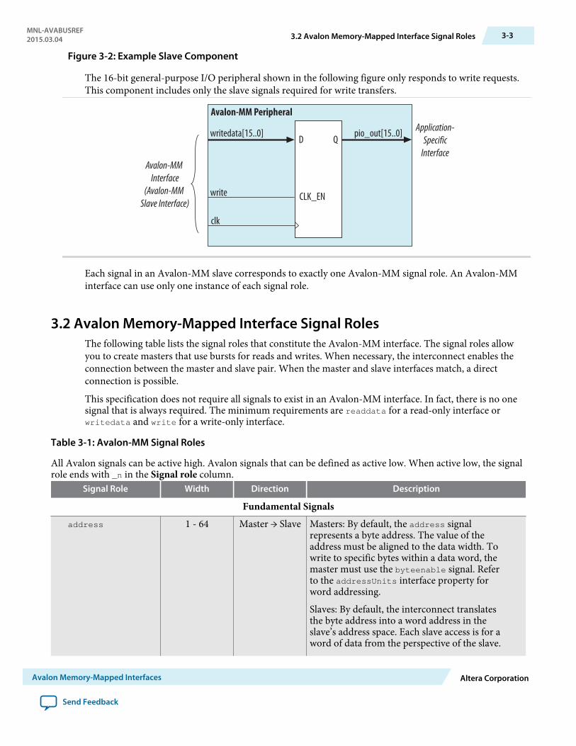
Figure 3-2: Example Slave Component
The 16-bit general-purpose I/O peripheral shown in the following figure only responds to write requests.This component includes only the slave signals required for write transfers.
Avalon-MM Interface
(Avalon-MM Slave Interface)
Application-Specific
Interface
writedata[15..0]
write
clk
pio_out[15..0]
CLK_EN
D Q
Avalon-MM Peripheral
Each signal in an Avalon-MM slave corresponds to exactly one Avalon-MM signal role. An Avalon-MMinterface can use only one instance of each signal role.
3.2 Avalon Memory-Mapped Interface Signal RolesThe following table lists the signal roles that constitute the Avalon-MM interface. The signal roles allowyou to create masters that use bursts for reads and writes. When necessary, the interconnect enables theconnection between the master and slave pair. When the master and slave interfaces match, a directconnection is possible.
This specification does not require all signals to exist in an Avalon-MM interface. In fact, there is no onesignal that is always required. The minimum requirements are readdata for a read-only interface orwritedata and write for a write-only interface.
Table 3-1: Avalon-MM Signal Roles
All Avalon signals can be active high. Avalon signals that can be defined as active low. When active low, the signalrole ends with _n in the Signal role column.
Signal Role Width Direction Description
Fundamental Signalsaddress 1 - 64 Master → Slave Masters: By default, the address signal
represents a byte address. The value of theaddress must be aligned to the data width. Towrite to specific bytes within a data word, themaster must use the byteenable signal. Referto the addressUnits interface property forword addressing.
Slaves: By default, the interconnect translatesthe byte address into a word address in theslave’s address space. Each slave access is for aword of data from the perspective of the slave.
MNL-AVABUSREF2015.03.04 3.2 Avalon Memory-Mapped Interface Signal Roles 3-3
Avalon Memory-Mapped Interfaces Altera Corporation
Send Feedback

Signal Role Width Direction Description
For example, address = 0= 0 selects the firstword of the slave. address = 1 selects thesecond word of the slave. Refer to theaddressUnits interface property for byteaddressing.
byteenable
byteenable_n
2, 4, 8, 16, 32,64, 128
Master → Slave Enables specific byte lane(s) during transfers oninterfaces of width greater than 8 bits. Each bitin byteenable corresponds to a byte inwritedata and readdata. The master bit <n>of byteenable indicates whether byte <n> isbeing written to. During writes, byteenablesspecify which bytes are being written to. Otherbytes should be ignored by the slave. Duringreads, byteenables indicate which bytes themaster is reading. Slaves that simply returnreaddata with no side effects are free to ignorebyteenables during reads. If an interface doesnot have a byteenable signal, the transferproceeds as if all byteenables are asserted.
When more than one bit of the byteenablesignal is asserted, all asserted lanes are adjacent.The number of adjacent lines must be a powerof 2. The specified bytes must be aligned on anaddress boundary for the size of the data. Forexample, the following values are legal for a 32-bit slave:
• 1111 writes full 32 bits• 0011 writes lower 2 bytes• 1100 writes upper 2 bytes• 0001 writes byte 0 only• 0010 writes byte 1 only• 0100 writes byte 2 only• 1000 writes byte 3 only
To avoid unintended side effects, Alterastrongly recommends that you use thebyteenable signal in systems with differentword sizes.
debugaccess 1 Master → Slave When asserted, allows the Nios II processor towrite on-chip memories configured as ROMs.
read
read_n
1 Master → Slave Asserted to indicate a read transfer. If present,readdata is required.
readdata 8,16, 32, 64,128, 256, 512,
1024
Slave → Master The readdata driven from the slave to themaster in response to a read transfer.
3-4 3.2 Avalon Memory-Mapped Interface Signal RolesMNL-AVABUSREF
2015.03.04
Altera Corporation Avalon Memory-Mapped Interfaces
Send Feedback
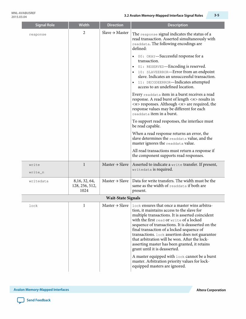
Signal Role Width Direction Description
response 2 Slave → Master The response signal indicates the status of aread transaction. Asserted simultaneously withreaddata. The following encodings aredefined:
• 00: OKAY—Successful response for atransaction.
• 01: RESERVED—Encoding is reserved.• 10: SLAVEERROR—Error from an endpoint
slave. Indicates an unsuccessful transaction.• 11: DECODEERROR—Indicates attempted
access to an undefined location.
Every readdata item in a burst receives a readresponse. A read burst of length <n> results in<n> responses. Although <n> are required, theresponse values may be different for eachreaddata item in a burst.
To support read responses, the interface mustbe read capable.
When a read response returns an error, theslave determines the readdata value, and themaster ignores the readdata value.
All read transactions must return a response ifthe component supports read responses.
write
write_n
1 Master → Slave Asserted to indicate a write transfer. If present,writedata is required.
writedata 8,16, 32, 64,128, 256, 512,
1024
Master → Slave Data for write transfers. The width must be thesame as the width of readdata if both arepresent.
Wait-State Signalslock 1 Master → Slave lock ensures that once a master wins arbitra‐
tion, it maintains access to the slave formultiple transactions. It is asserted coincidentwith the first read or write of a lockedsequence of transactions. It is deasserted on thefinal transaction of a locked sequence oftransactions. lock assertion does not guaranteethat arbitration will be won. After the lock-asserting master has been granted, it retainsgrant until it is deasserted.
A master equipped with lock cannot be a burstmaster. Arbitration priority values for lock-equipped masters are ignored.
MNL-AVABUSREF2015.03.04 3.2 Avalon Memory-Mapped Interface Signal Roles 3-5
Avalon Memory-Mapped Interfaces Altera Corporation
Send Feedback

Signal Role Width Direction Description
lock is particularly useful for read-modify-write (RMW) operations. The typical read-modify-write operation includes the followingsteps:
1. Master A asserts lock and reads 32-bit datathat has multiple bit fields.
2. Master A deasserts lock, changes one bitfield, and writes the 32-bit data back.
lock prevents master B from performing awrite between Master A’s read and write.
waitrequest
waitrequest_n
1 Slave → Master Asserted by the slave when it is unable torespond to a read or write request. Forces themaster to wait until the interconnect is ready toproceed with the transfer. At the start of alltransfers, a master initiates the transfer andwaits until waitrequest is deasserted. A mastermust make no assumption about the assertionstate of waitrequest when the master is idle:waitrequest may be high or low, dependingon system properties.
When waitrequest is asserted, master controlsignals to the slave are to remain constant withthe exception of beginbursttransfer. For atiming diagram illustrating the beginburst-transfer signal, refer to the figure in ReadBursts.An Avalon-MM slave may assert waitrequestduring idle cycles. An Avalon-MM master mayinitiate a transaction when waitrequest isasserted and wait for that signal to bedeasserted. To avoid system lockup, a slavedevice should assert waitrequest when inreset.
Pipeline Signals
3-6 3.2 Avalon Memory-Mapped Interface Signal RolesMNL-AVABUSREF
2015.03.04
Altera Corporation Avalon Memory-Mapped Interfaces
Send Feedback

Signal Role Width Direction Description
readdatavalid
readdatavalid_n
1 Slave → Master Used for variable-latency, pipelined readtransfers. When asserted, indicates that thereaddata signal contains valid data. A slavewith readdatavalid must assert this signal forone cycle for each read access received. Theremust be at least one cycle of latency betweenacceptance of the read and assertion ofreaddatavalid. For a timing diagramillustrating the readdatavalid signal, refer toPipelined Read Transfer with Variable Latency.
A slave may assert readdatavalid to transferdata to the master independently of whether ornot the slave is stalling a new command withwaitrequest.
Required if the master supports pipelined reads.Bursting masters with read functionality mustinclude the readdatavalid signal.
Burst Signalsburstcount 1 – 11 Master → Slave Used by bursting masters to indicate the
number of transfers in each burst. The value ofthe maximum burstcount parameter must be apower of 2. A burstcount interface of width <n>can encode a max burst of size 2(<n>-1). Forexample, a 4-bit burstcount signal can supporta maximum burst count of 8. The minimumburstcount is 1. The constantBurstBehaviorproperty controls the timing of the burstcountsignal. Bursting masters with read functionalitymust include the readdatavalid signal.
For bursting masters and slaves using byteaddresses, the following restriction applies tothe width of the address:
<address_w> >= <burstcount_w>
+log2(<symbols_per_word_of_interface>).
For bursting masters and slaves using wordaddresses, the log2 term above is omitted.
MNL-AVABUSREF2015.03.04 3.2 Avalon Memory-Mapped Interface Signal Roles 3-7
Avalon Memory-Mapped Interfaces Altera Corporation
Send Feedback
Signal Role Width Direction Description
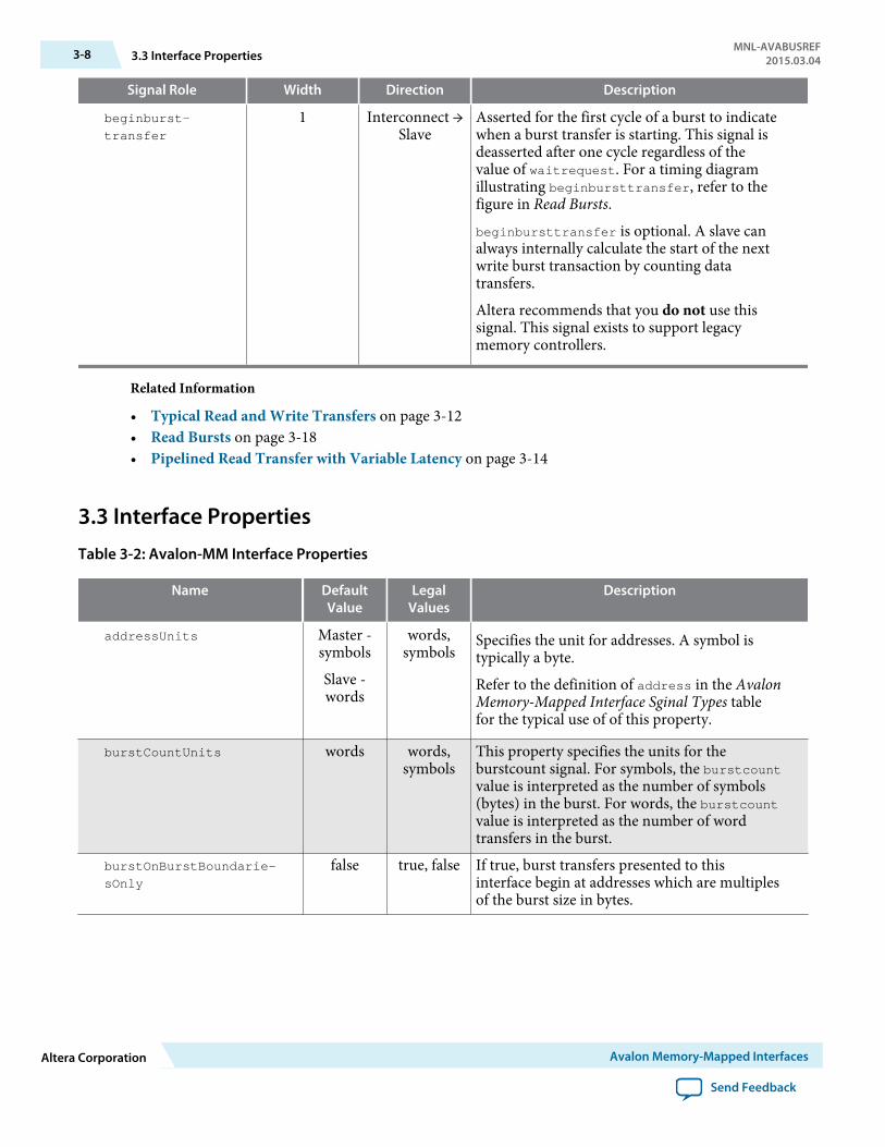
beginburst-
transfer
1 Interconnect →Slave
Asserted for the first cycle of a burst to indicatewhen a burst transfer is starting. This signal isdeasserted after one cycle regardless of thevalue of waitrequest. For a timing diagramillustrating beginbursttransfer, refer to thefigure in Read Bursts.beginbursttransfer is optional. A slave canalways internally calculate the start of the nextwrite burst transaction by counting datatransfers.
Altera recommends that you do not use thissignal. This signal exists to support legacymemory controllers.
Related Information
• Typical Read and Write Transfers on page 3-12• Read Bursts on page 3-18• Pipelined Read Transfer with Variable Latency on page 3-14
3.3 Interface PropertiesTable 3-2: Avalon-MM Interface Properties
Name DefaultValue
LegalValues
Description
addressUnits Master -symbols
Slave -words
words,symbols
Specifies the unit for addresses. A symbol istypically a byte.
Refer to the definition of address in the AvalonMemory-Mapped Interface Sginal Types tablefor the typical use of of this property.
burstCountUnits words words,symbols
This property specifies the units for theburstcount signal. For symbols, the burstcountvalue is interpreted as the number of symbols(bytes) in the burst. For words, the burstcountvalue is interpreted as the number of wordtransfers in the burst.
burstOnBurstBoundarie-
sOnly
false true, false If true, burst transfers presented to thisinterface begin at addresses which are multiplesof the burst size in bytes.
3-8 3.3 Interface PropertiesMNL-AVABUSREF
2015.03.04
Altera Corporation Avalon Memory-Mapped Interfaces
Send Feedback

Name DefaultValue
LegalValues
Description
constantBurstBehavior Master -false
Slave -false
true, false Masters: When true, declares that the masterholds address and burstcount constantthroughout a burst transaction. When false(default), declares that the master holds addressand burstcount constant only for the first beatof a burst.
Slaves: When true, declares that the slaveexpects address and burstcount to be heldconstant throughout a burst. When false(default), declares that the slave samplesaddress and burstcount only on the first beat ofa burst.
holdTime(1) 0 0 – 1000cycles
Specifies time in timingUnits between thedeassertion of write and the deassertion ofaddress and data. (Only applies to writetransactions.)
linewrapBursts false true, false Some memory devices implement a wrappingburst instead of an incrementing burst. When awrapping burst reaches a burst boundary, theaddress wraps back to the previous burstboundary. Only the low-order bits are requiredfor address counting. For example, a wrappingburst to address 0xC with burst boundariesevery 32 bytes across a 32-bit interface writes tothe following addresses:
• 0xC• 0x10• 0x14• 0x18• 0x1C• 0x0• 0x4• 0x8
MNL-AVABUSREF2015.03.04 3.3 Interface Properties 3-9
Avalon Memory-Mapped Interfaces Altera Corporation
Send Feedback

Name DefaultValue
LegalValues
Description
maximumPendingReadTran-
sactions (1)
1(2) 1 – 64 Slaves: This parameter is the maximum numberof pending reads that the slave can queue. For atiming diagram that illustrates this property,refer to Figure 3-5. Do not set this parameter to0. (For backwards compatibility, the softwaresupports a parameter setting of 0. However,you should not use this setting in new designs).Refer to Pipelined Read Transfer withVariable Latency on page 3-14 for additionalinformation about using waitrequest andreaddatavalid with multiple outstandingreads.
Masters: This property is the maximumnumber of outstanding read transactions thatthe master can generate. Do not set thisparameter to 0. (For backwards compatibility,the software supports a parameter setting of 0.However, you should not use this setting innew designs).
readLatency(1) 0 0 – 63 Read latency for fixed-latency Avalon-MMslaves. Not used on interfaces that include thereaddatavalid signal. For a timing diagramthat uses a fixed latency read, refer to Figure3-6.
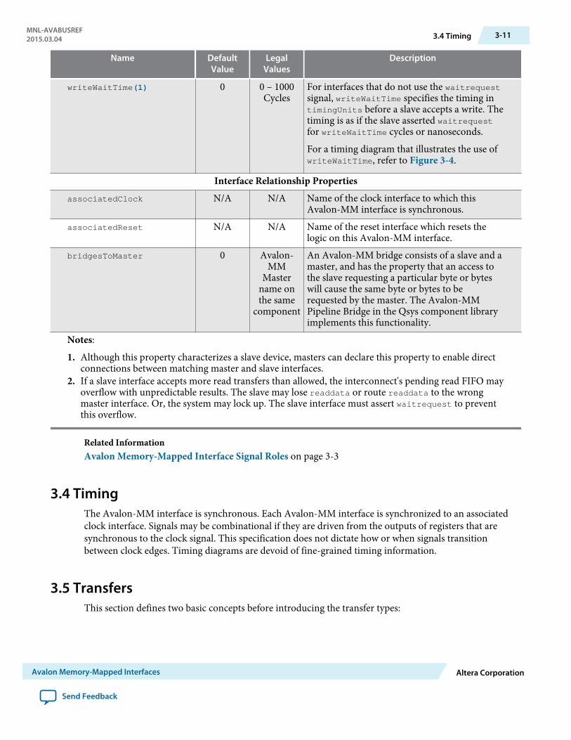
readWaitTime(1) 1 0 – 1000cycles
For interfaces that don’t use the waitrequestsignal. readWaitTime indicates the timing intimingUnits before the slave accepts a readcommand. The timing is as if the slave assertedwaitrequest for readWaitTime cycles.
setupTime(1) 0 0 – 1000cycles
Specifies time in timingUnits between theassertion of address and data and assertion ofread or write.
timingUnits(1) cycles cycles,nanosecon
ds
Specifies the units for setupTime, holdTime,writeWaitTime and readWaitTime. Use cyclesfor synchronous devices and nanoseconds forasynchronous devices. Almost all Avalon-MMslave devices are synchronous.
An Avalon-MM component that bridges froman Avalon-MM slave interface to an off-chipdevice may be asynchronous. That off-chipdevice might have a fixed settling time for busturnaround.
3-10 3.3 Interface PropertiesMNL-AVABUSREF
2015.03.04
Altera Corporation Avalon Memory-Mapped Interfaces
Send Feedback
Name DefaultValue
LegalValues
Description
writeWaitTime(1) 0 0 – 1000Cycles
For interfaces that do not use the waitrequestsignal, writeWaitTime specifies the timing intimingUnits before a slave accepts a write. Thetiming is as if the slave asserted waitrequestfor writeWaitTime cycles or nanoseconds.
For a timing diagram that illustrates the use ofwriteWaitTime, refer to Figure 3-4.
Interface Relationship PropertiesassociatedClock N/A N/A Name of the clock interface to which this
Avalon-MM interface is synchronous.associatedReset N/A N/A Name of the reset interface which resets the
logic on this Avalon-MM interface.bridgesToMaster 0 Avalon-
MMMaster
name onthe same
component
An Avalon-MM bridge consists of a slave and amaster, and has the property that an access tothe slave requesting a particular byte or byteswill cause the same byte or bytes to berequested by the master. The Avalon-MMPipeline Bridge in the Qsys component libraryimplements this functionality.
Notes:
1. Although this property characterizes a slave device, masters can declare this property to enable directconnections between matching master and slave interfaces.
2. If a slave interface accepts more read transfers than allowed, the interconnect's pending read FIFO mayoverflow with unpredictable results. The slave may lose readdata or route readdata to the wrongmaster interface. Or, the system may lock up. The slave interface must assert waitrequest to preventthis overflow.
Related InformationAvalon Memory-Mapped Interface Signal Roles on page 3-3
3.4 TimingThe Avalon-MM interface is synchronous. Each Avalon-MM interface is synchronized to an associatedclock interface. Signals may be combinational if they are driven from the outputs of registers that aresynchronous to the clock signal. This specification does not dictate how or when signals transitionbetween clock edges. Timing diagrams are devoid of fine-grained timing information.
3.5 TransfersThis section defines two basic concepts before introducing the transfer types:
MNL-AVABUSREF2015.03.04 3.4 Timing 3-11
Avalon Memory-Mapped Interfaces Altera Corporation
Send Feedback

• Transfer—A transfer is a read or write operation of a word or one or more symbol of data. Transfersoccur between an Avalon-MM interface and the interconnect. Transfers take one or more clock cyclesto complete.
Both masters and slaves are part of a transfer. The Avalon-MM master initiates the transfer and theAvalon-MM slave responds to it.
• Master-slave pair—This term refers to the master interface and slave interface involved in a transfer.During a transfer, the master interface control and data signals pass through the interconnect fabricand interact with the slave interface.
3.5.1 Typical Read and Write TransfersThis section describes a typical Avalon-MM interface that supports read and write transfers with slave-controlled waitrequest. The slave can stall the interconnect for as many cycles as required by assertingthe waitrequest signal. If a slave uses waitrequest for either read or write transfers, it must usewaitrequest for both.
A slave typically receives address, byteenable, read or write, and writedata after the rising edge of theclock. A slave asserts waitrequest before the rising clock edge to hold off transfers. When the slaveasserts waitrequest, the transfer is delayed. While waitrequest is asserted, the address and othercontrol signals are held constant. Transfers complete on the rising edge of the first clk after the slaveinterface deasserts waitrequest.
There is no limit on how long a slave interface can stall. Therefore, you must ensure that a slave interfacedoes not assert waitrequest indefinitely. The following figure shows read and write transfers usingwaitrequest. In this example, the master and slave both have a readdatavalid signal.
Note: waitrequest can be decoupled from the read and write request signals. waitrequest may beasserted during idle cycles. An Avalon-MM master may initiate a transaction when waitrequest isasserted and wait for that signal to be deasserted. Decoupling waitrequest from read and writerequests may improve system timing. Decoupling eliminates a combinational loop including theread, write, and waitrequest signals.
Figure 3-3: Read and Write Transfers with Waitrequest
clk
address
byteenable
read
write
waitrequest
readdata
writedata
address
byteenable
readdata
writedata
1 2 3 4 5 76
response
readdatavalid
response
3-12 3.5.1 Typical Read and Write TransfersMNL-AVABUSREF
2015.03.04
Altera Corporation Avalon Memory-Mapped Interfaces
Send Feedback
The numbers in this timing diagram, mark the following transitions:
1. address, byteenable, and read are asserted after the rising edge of clk. The slave assertswaitrequest, stalling the transfer.
2. waitrequest is sampled. Because waitrequest is asserted, the cycle becomes a wait-state. address,read, write, and byteenable remain constant.
3. The slave deasserts waitrequest after the rising edge of clk.4. readdata, response and deasserted waitrequest are sampled, completing the transfer.5. address, writedata, byteenable, and write signals are asserted after the rising edge of clk. The slave
asserts waitrequest stalling the transfer.6. The slave deasserts waitrequest after the rising edge of clk.7. The slave captures write data ending the transfer.
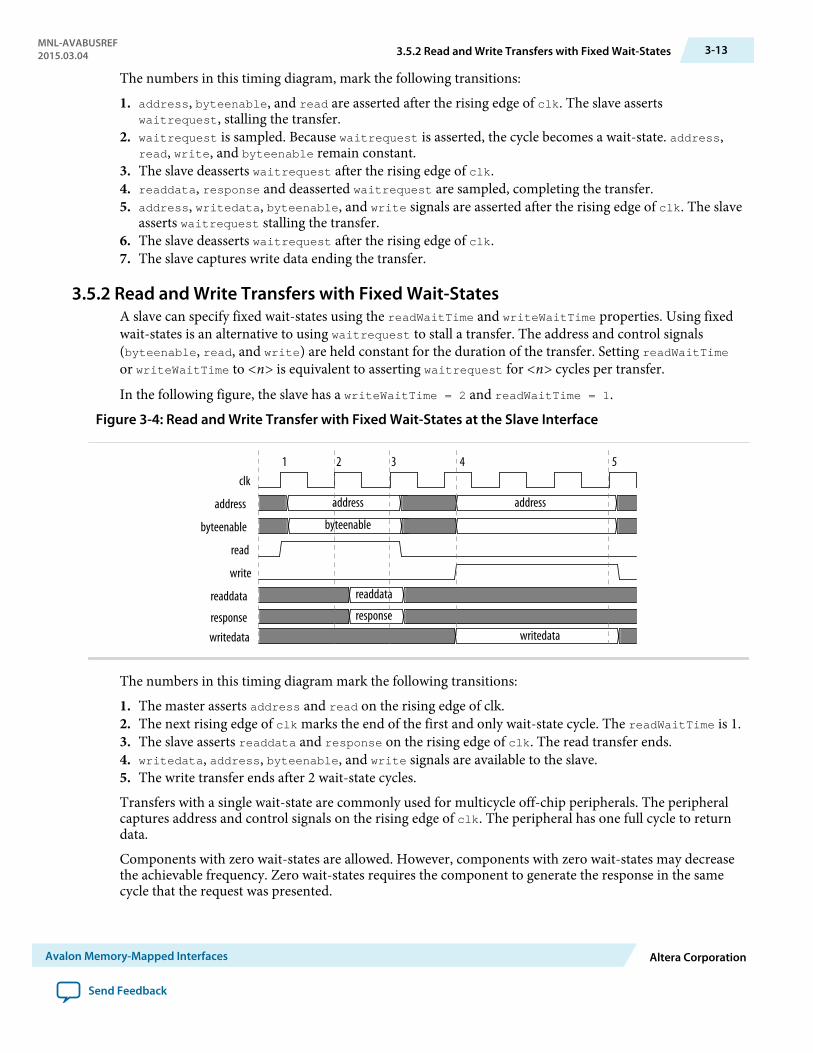
3.5.2 Read and Write Transfers with Fixed Wait-StatesA slave can specify fixed wait-states using the readWaitTime and writeWaitTime properties. Using fixedwait-states is an alternative to using waitrequest to stall a transfer. The address and control signals(byteenable, read, and write) are held constant for the duration of the transfer. Setting readWaitTimeor writeWaitTime to <n> is equivalent to asserting waitrequest for <n> cycles per transfer.
In the following figure, the slave has a writeWaitTime = 2 and readWaitTime = 1.
Figure 3-4: Read and Write Transfer with Fixed Wait-States at the Slave Interface
clk
address
byteenable byteenable
read
write
readdata
writedata
address address
readdata
response response
writedata
4 51 2 3
The numbers in this timing diagram mark the following transitions:
1. The master asserts address and read on the rising edge of clk.2. The next rising edge of clk marks the end of the first and only wait-state cycle. The readWaitTime is 1.3. The slave asserts readdata and response on the rising edge of clk. The read transfer ends.4. writedata, address, byteenable, and write signals are available to the slave.5. The write transfer ends after 2 wait-state cycles.
Transfers with a single wait-state are commonly used for multicycle off-chip peripherals. The peripheralcaptures address and control signals on the rising edge of clk. The peripheral has one full cycle to returndata.
Components with zero wait-states are allowed. However, components with zero wait-states may decreasethe achievable frequency. Zero wait-states requires the component to generate the response in the samecycle that the request was presented.
MNL-AVABUSREF2015.03.04 3.5.2 Read and Write Transfers with Fixed Wait-States 3-13
Avalon Memory-Mapped Interfaces Altera Corporation
Send Feedback

3.5.3 Pipelined TransfersAvalon-MM pipelined read transfers increase the throughput for synchronous slave devices that requireseveral cycles to return data for the first access. Such devices can can typically return one data value percycle for some time thereafter. New pipelined read transfers can start before readdata for the previoustransfers is returned. Write transfers cannot be pipelined.
A pipelined read transfer has an address phase and a data phase. A master initiates a transfer bypresenting the address during the address phase. A slave fulfills the transfer by delivering the data duringthe data phase. The address phase for a new transfer (or multiple transfers) can begin before the dataphase of a previous transfer completes. The delay is called pipeline latency. The pipeline latency is theduration from the end of the address phase to the beginning of the data phase.
Transfer timing for wait-states and pipeline latency have the following key differences:
• Wait-states—Wait-states determine the length of the address phase. Wait-states limit the maximumthroughput of a . If a slave requires one wait-state to respond to a transfer request, the requires twoclock cycles per transfer.
• Pipeline Latency—Pipeline latency determines the time until data is returned independently of theaddress phase. A pipelined slave with no wait-states can sustain one transfer per cycle. However, it mayrequire several cycles of latency to return the first unit of data.
Wait-states and pipelined reads can be supported concurrently. Pipeline latency can be either fixed orvariable.
3.5.3.1 Pipelined Read Transfer with Variable LatencyAfter capturing address and control signals, an Avalon-MM pipelined slave takes one or more cycles toproduce data. A pipelined slave may have multiple pending read transfers at any given time. Variable-latency pipelined read transfers require one additional signal, readdatavalid. readdatavalid indicateswhen read data is valid. Variable-latency pipelined read transfers also include the same set of signals asnon-pipelined read transfers. Slave peripherals that use readdatavalid are considered pipelined withvariable latency. The readdata and readdatavalid signals corresponding to a particular read commandcan be asserted the cycle after that read command is asserted, at the earliest.
The slave must return readdata in the same order that it accepted the read commands. Pipelined slaveports with variable latency must use waitrequest. The slave can assert waitrequest to stall transfers tomaintain an acceptable number of pending transfers. A slave may assert readdatavalid to transfer datato the master independently of whether or not the slave is stalling a new command with waitrequest.
Note: The maximum number of pending transfers is a property of the slave interface. The interconnectfabric builds logic to route readdata to requesting masters using this number. The slave interface,not the interconnect fabric, must track the number of pending reads. The slave must assertwaitrequest to prevent the number of pending reads from exceeding the maximum number.
3-14 3.5.3 Pipelined TransfersMNL-AVABUSREF
2015.03.04
Altera Corporation Avalon Memory-Mapped Interfaces
Send Feedback
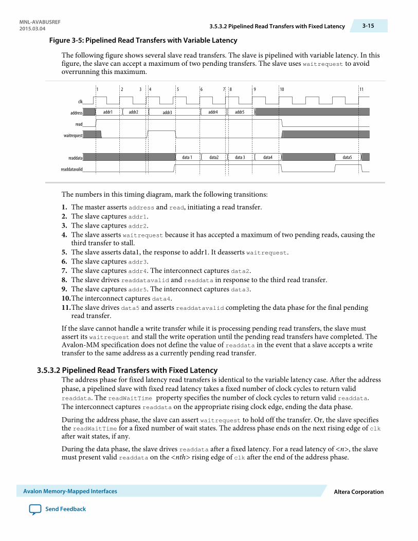
Figure 3-5: Pipelined Read Transfers with Variable Latency
The following figure shows several slave read transfers. The slave is pipelined with variable latency. In thisfigure, the slave can accept a maximum of two pending transfers. The slave uses waitrequest to avoidoverrunning this maximum.
clk
address
read
waitrequest
readdata
readdatavalid
addr1 addr2 addr3 addr4 addr5
data 1 data2 data 3 data4 data5
1 2 3 4 6 115 9 1087
The numbers in this timing diagram, mark the following transitions:
1. The master asserts address and read, initiating a read transfer.2. The slave captures addr1.3. The slave captures addr2.4. The slave asserts waitrequest because it has accepted a maximum of two pending reads, causing the
third transfer to stall.5. The slave asserts data1, the response to addr1. It deasserts waitrequest.6. The slave captures addr3.7. The slave captures addr4. The interconnect captures data2.8. The slave drives readdatavalid and readdata in response to the third read transfer.9. The slave captures addr5. The interconnect captures data3.10.The interconnect captures data4.11.The slave drives data5 and asserts readdatavalid completing the data phase for the final pending
read transfer.
If the slave cannot handle a write transfer while it is processing pending read transfers, the slave mustassert its waitrequest and stall the write operation until the pending read transfers have completed. TheAvalon-MM specification does not define the value of readdata in the event that a slave accepts a writetransfer to the same address as a currently pending read transfer.
3.5.3.2 Pipelined Read Transfers with Fixed LatencyThe address phase for fixed latency read transfers is identical to the variable latency case. After the addressphase, a pipelined slave with fixed read latency takes a fixed number of clock cycles to return validreaddata. The readWaitTime property specifies the number of clock cycles to return valid readdata.The interconnect captures readdata on the appropriate rising clock edge, ending the data phase.
During the address phase, the slave can assert waitrequest to hold off the transfer. Or, the slave specifiesthe readWaitTime for a fixed number of wait states. The address phase ends on the next rising edge of clkafter wait states, if any.
During the data phase, the slave drives readdata after a fixed latency. For a read latency of <n>, the slavemust present valid readdata on the <nth> rising edge of clk after the end of the address phase.
MNL-AVABUSREF2015.03.04 3.5.3.2 Pipelined Read Transfers with Fixed Latency 3-15
Avalon Memory-Mapped Interfaces Altera Corporation
Send Feedback
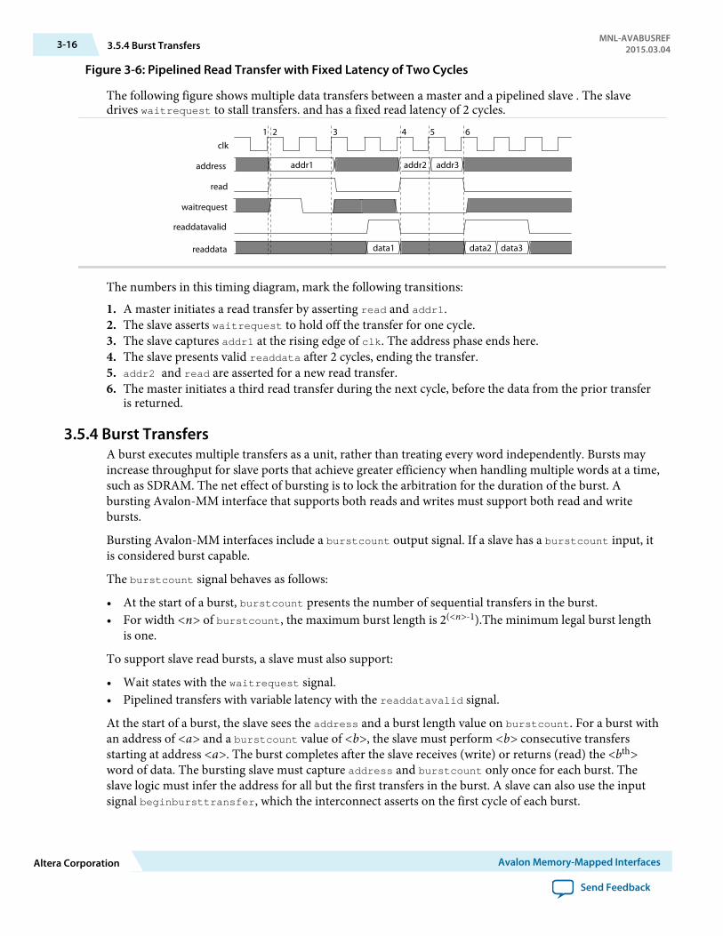
Figure 3-6: Pipelined Read Transfer with Fixed Latency of Two Cycles
The following figure shows multiple data transfers between a master and a pipelined slave . The slavedrives waitrequest to stall transfers. and has a fixed read latency of 2 cycles.
clk
address
read
waitrequest
readdata
addr1 addr2 addr3
data1 data2 data3
1 2 3 4 5 6
readdatavalid
The numbers in this timing diagram, mark the following transitions:
1. A master initiates a read transfer by asserting read and addr1.2. The slave asserts waitrequest to hold off the transfer for one cycle.3. The slave captures addr1 at the rising edge of clk. The address phase ends here.4. The slave presents valid readdata after 2 cycles, ending the transfer.5. addr2 and read are asserted for a new read transfer.6. The master initiates a third read transfer during the next cycle, before the data from the prior transfer
is returned.
3.5.4 Burst TransfersA burst executes multiple transfers as a unit, rather than treating every word independently. Bursts mayincrease throughput for slave ports that achieve greater efficiency when handling multiple words at a time,such as SDRAM. The net effect of bursting is to lock the arbitration for the duration of the burst. Abursting Avalon-MM interface that supports both reads and writes must support both read and writebursts.
Bursting Avalon-MM interfaces include a burstcount output signal. If a slave has a burstcount input, itis considered burst capable.
The burstcount signal behaves as follows:
• At the start of a burst, burstcount presents the number of sequential transfers in the burst.• For width <n> of burstcount, the maximum burst length is 2(<n>-1).The minimum legal burst length
is one.
To support slave read bursts, a slave must also support:
• Wait states with the waitrequest signal.• Pipelined transfers with variable latency with the readdatavalid signal.
At the start of a burst, the slave sees the address and a burst length value on burstcount. For a burst withan address of <a> and a burstcount value of <b>, the slave must perform <b> consecutive transfersstarting at address <a>. The burst completes after the slave receives (write) or returns (read) the <bth>word of data. The bursting slave must capture address and burstcount only once for each burst. Theslave logic must infer the address for all but the first transfers in the burst. A slave can also use the inputsignal beginbursttransfer, which the interconnect asserts on the first cycle of each burst.
3-16 3.5.4 Burst TransfersMNL-AVABUSREF
2015.03.04
Altera Corporation Avalon Memory-Mapped Interfaces
Send Feedback
3.5.4.1 Write BurstsThese rules apply when a write burst begins with burstcount greater than one:
• When a burstcount of <n> is presented at the beginning of the burst, the slave must accept <n>successive units of writedata to complete the burst. Arbitration between the master-slave pair islocked until the burst completes. This lock guarantees that no other master can execute transactions onthe slave until the write burst is completes.
• The slave must only capture writedata when write is asserted. During the burst, the master candeassert write indicating that writedata is invalid. Deasserting write does not terminate the burst.It delays it. When a burst is delayed, no other masters can access the slave, reducing the transferefficiency.
• The constantBurstBehavior property specifies the behavior of the burst signals. When constant-BurstBehavior is true for a master, it indicates that the master holds address and burstcount stablethroughout a burst. When constantBurstBehavior is false, it indicates that the master holds addressand burstcount stable only for the first transaction of a burst. When true for a slave, constantBurst-Behavior declares that the slave expects address and burstcount to be held stable throughout aburst. When constantBurstBehavior is false, it indicates that the slave samples address andburstcount only on the first transaction of a burst.
• The slave can delay a transfer by asserting waitrequest forcing writedata, write, burstcound, andbyteenable to be held constant.
• The functionality of the byteenable signal is the same for bursting and non-bursting slaves. For a 32-bit master burst-writing to a 64-bit slave, starting at byte address 4, the first write transfer seen by theslave is at its address 0, with byteenable = 8'b11110000. The byteenables can change for differentwords of the burst.
• The byteenable signals do not all have to be asserted. A burst master writing partial words can use thebyteenable signal to identify the data being written.
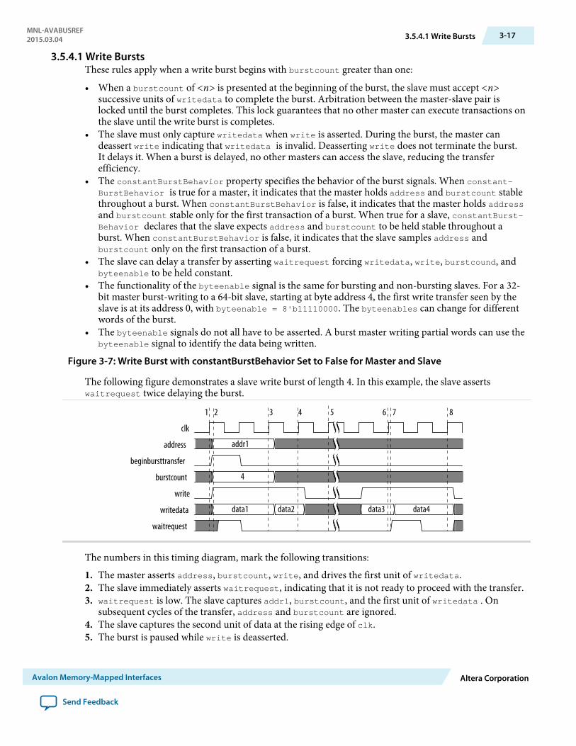
Figure 3-7: Write Burst with constantBurstBehavior Set to False for Master and Slave
The following figure demonstrates a slave write burst of length 4. In this example, the slave assertswaitrequest twice delaying the burst.
clk
address
beginbursttransfer
burstcount
write
writedata
waitrequest
addr1
4
data1 data2 data3 data4
1 2 3 4 5 76 8
The numbers in this timing diagram, mark the following transitions:
1. The master asserts address, burstcount, write, and drives the first unit of writedata.2. The slave immediately asserts waitrequest, indicating that it is not ready to proceed with the transfer.3. waitrequest is low. The slave captures addr1, burstcount, and the first unit of writedata . On
subsequent cycles of the transfer, address and burstcount are ignored.4. The slave captures the second unit of data at the rising edge of clk.5. The burst is paused while write is deasserted.
MNL-AVABUSREF2015.03.04 3.5.4.1 Write Bursts 3-17
Avalon Memory-Mapped Interfaces Altera Corporation
Send Feedback
6. The slave captures the third unit of data at the rising edge of clk.7. The slave asserts waitrequest. In response, all outputs are held constant through another clock cycle.8. The slave captures the last unit of data on this rising edge of clk. The slave write burst ends.
In the figure above, the beginbursttransfer signal is asserted for the first clock cycle of a burst and isdeasserted on the next clock cycle. Even if the slave asserts waitrequest, the beginbursttransfer signalis only asserted for the first clock cycle.
For information about Avalon-MM properties, refer to Table 3-2.
Related InformationInterface Properties on page 3-8
3.5.4.2 Read BurstsRead bursts are similar to pipelined read transfers with variable latency. A read burst has distinct addressand data phases. readdatavalid indicates when the slave is presenting valid readdata. Unlike pipelinedread transfers, a single read burst address results in multiple data transfers.
These rules apply to read bursts:
• When burstcount is <n>, the slave must return <n> words of readdata to complete the burst.• The slave presents each word by providing readdata and asserting readdatavalid for a cycle.
Deassertion of readdatavalid delays but does not terminate the burst data phase.• The byteenables presented with a read burst command apply to all cycles of the burst. A byteenable
value of 1 means that the least significant byte is being read across all of the read cycles.
Note: Altera recommends that burst capable slaves not have read side effects. (This specification does notguarantee how many bytes will be read from the slave in order to satisfy a request.)
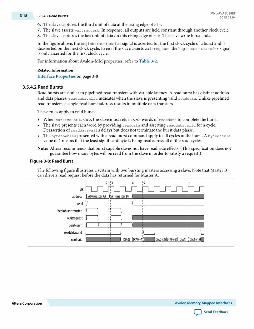
Figure 3-8: Read Burst
The following figure illustrates a system with two bursting masters accessing a slave. Note that Master Bcan drive a read request before the data has returned for Master A.
clk
address
read
beginbursttransfer
waitrequest
burstcount
readdatavalid
readdata
A0 (master A) A1 (master B)
4 2
D(A0) D(A0+1) D(A0+2) D(A0+3) D(A1) D(A1+1)
2 3 5 61 4
3-18 3.5.4.2 Read BurstsMNL-AVABUSREF
2015.03.04
Altera Corporation Avalon Memory-Mapped Interfaces
Send Feedback
The numbers in this timing diagram, mark the following transitions:
1. Master A asserts address (A0), burstcount, and read after the rising edge of clk. The slave assertswaitrequest, causing all inputs except beginbursttransfer to be held constant through anotherclock cycle.
2. The slave captures A0 and burstcount at this rising edge of clk. A new transfer could start on the nextcycle.
3. Master B drives address (A1), burstcount, and read. The slave asserts waitrequest, causing allinputs except beginbursttransfer to be held constant. The slave could have returned read data fromthe first read request at this time, at the earliest.
4. The slave presents valid readdata and asserts readdatavalid, transferring the first word of data formaster A.
5. The second word for master A is transferred. The slave deasserts readdatavalid pausing the readburst. The slave port can keep readdatavalid deasserted for an arbitrary number of clock cycles.
6. The first word for master B is returned.
3.5.4.3 Line–Wrapped BurstsProcessors with instruction caches gain efficiency by using line-wrapped bursts. When a processorrequests data that is not in the cache, the cache controller must refill the entire cache line. For a processorwith a cache line size of 64 bytes, a cache miss causes 64 bytes to be read from memory. If the processorreads from address 0xC when the cache miss occurred, then an inefficient cache controller could issue aburst at address 0, resulting in data from read addresses 0x0, 0x4, 0x8, 0xC, 0x10, 0x14, 0x18, . . . 0x3C.The requested data is not available until the fourth read. With line-wrapping bursts, the address order is0xC, 0x10, 0x14, 0x18, . . . 0x3C, 0x0, 0x4, and 0x8. The requested data is returned first. The entire cacheline is eventually refilled from memory.
3.6 Address AlignmentThe interconnect only supports aligned accesses. A master can only issue addresses that are a multiple ofits data width in symbols. A master can write partial words by deasserting some byteenables. Forexample, a write of 2 bytes at address 2 would have 4’b1100 for the byteenables.
3.7 Avalon-MM Slave AddressingDynamic bus sizing manages data during transfers between master-slave pairs of differing data widths.Slave data are aligned in contiguous bytes in the master address space.
If the master data width is wider than the slave data width, words in the master address space map tomultiple locations in the slave address space. For example, a 32-bit master read from a 16-bit slave resultsin two read transfers on the slave side. The reads are to consecutive addresses.
If the master is narrower than the slave, then the interconnect manages the slave byte lanes. Duringmaster read transfers, the interconnect presents only the appropriate byte lanes of slave data to thenarrower master. During master write transfers, the interconnect automatically asserts the byteenablesignals to write data only to the specified slave byte lanes.
Slaves must have a data width of 8, 16, 32, 64, 128, 256, 512 or 1024 bits. The following table shows howslave data of various widths is aligned within a 32-bit master performing full-word accesses. In this table,OFFSET[N] refers to a slave word size offset into the slave address space.
MNL-AVABUSREF2015.03.04 3.5.4.3 Line–Wrapped Bursts 3-19
Avalon Memory-Mapped Interfaces Altera Corporation
Send Feedback

Table 3-3: Dynamic Bus Sizing Master-to-Slave Address Mapping
Master ByteAddress (1) Access
32-Bit Master Data
When Accessing an 8-Bit Slave Interface
When Accessing a 16-Bit Slave Interface
When Accessing a 64-Bit Slave Interface
0x00
1 OFFSET[0]7..0 OFFSET[0]15..0 (2) OFFSET[0]31..0
2 OFFSET[1]7..0 OFFSET[1]15..0 —3 OFFSET[2]7..0 — —4 OFFSET[3]7..0 — —
0x04
1 OFFSET[4]7..0 OFFSET[2]15..0 OFFSET[0]63..32
2 OFFSET[5]7..0 OFFSET[3]15..0 —3 OFFSET[6]7..0 — —4 OFFSET[7]7..0 — —
0x08
1 OFFSET[8]7..0 OFFSET[4]15..0 OFFSET[1]31..0
2 OFFSET[9]7..0 OFFSET[5]15..0 —3 OFFSET[10]7..0 — —4 OFFSET[11]7..0 — —
0x0C
1 OFFSET[12]7..0 OFFSET[6]15..0 OFFSET[1]63..32
2 OFFSET[13]7..0 OFFSET[7]15..0 —3 OFFSET[14]7..0 — —4 OFFSET[15]7..0 — —
... ... ...
Notes:
1. Although the master is issuing byte addresses, it is accessing full 32-bit words.2. For all slave entries, [<n>] is the word offset and the subscript values are the bits in the word.
3-20 3.7 Avalon-MM Slave AddressingMNL-AVABUSREF
2015.03.04
Altera Corporation Avalon Memory-Mapped Interfaces
Send Feedback
Avalon Interrupt Interfaces 42015.03.04
MNL-AVABUSREF Subscribe Send Feedback
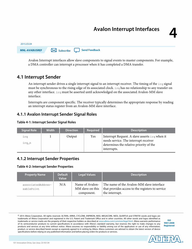
Avalon Interrupt interfaces allow slave components to signal events to master components. For example,a DMA controller can interrupt a processor when it has completed a DMA transfer.
4.1 Interrupt SenderAn interrupt sender drives a single interrupt signal to an interrupt receiver. The timing of the irq signalmust be synchronous to the rising edge of its associated clock. irq has no relationship to any transfer onany other interface. irq must be asserted until acknowledged on the associated Avalon-MM slaveinterface.
Interrupts are component specific. The receiver typically determines the appropriate response by readingan interrupt status register from an Avalon-MM slave interface.
4.1.1 Avalon Interrupt Sender Signal Roles
Table 4-1: Interrupt Sender Signal Roles
Signal Role Width Direction Required Description
irq
irq_n
1 Output Yes Interrupt Request. A slave asserts irq when itneeds service. The interrupt receiverdetermines the relative priority of theinterrupts.
4.1.2 Interrupt Sender Properties
Table 4-2: Interrupt Sender Properties
Property Name DefaultValue
Legal Values Description
associatedAddres-
sablePoint
N/A Name of Avalon-MM slave on this
component.
The name of the Avalon-MM slave interfacethat provides access to the registers to servicethe interrupt.
© 2015 Altera Corporation. All rights reserved. ALTERA, ARRIA, CYCLONE, ENPIRION, MAX, MEGACORE, NIOS, QUARTUS and STRATIX words and logos aretrademarks of Altera Corporation and registered in the U.S. Patent and Trademark Office and in other countries. All other words and logos identified astrademarks or service marks are the property of their respective holders as described at www.altera.com/common/legal.html. Altera warrants performanceof its semiconductor products to current specifications in accordance with Altera's standard warranty, but reserves the right to make changes to anyproducts and services at any time without notice. Altera assumes no responsibility or liability arising out of the application or use of any information,product, or service described herein except as expressly agreed to in writing by Altera. Altera customers are advised to obtain the latest version of devicespecifications before relying on any published information and before placing orders for products or services.
ISO9001:2008Registered
www.altera.com101 Innovation Drive, San Jose, CA 95134
Property Name DefaultValue
Legal Values Description
associatedClock N/A Name of a clockinterface on this
component.
The name of the clock interface to which thisinterrupt sender is synchronous. The senderand receiver may have different values for thisproperty.
associatedReset N/A Name of a resetinterface on this
component.
The name of the reset interface to which thisinterrupt sender is synchronous.
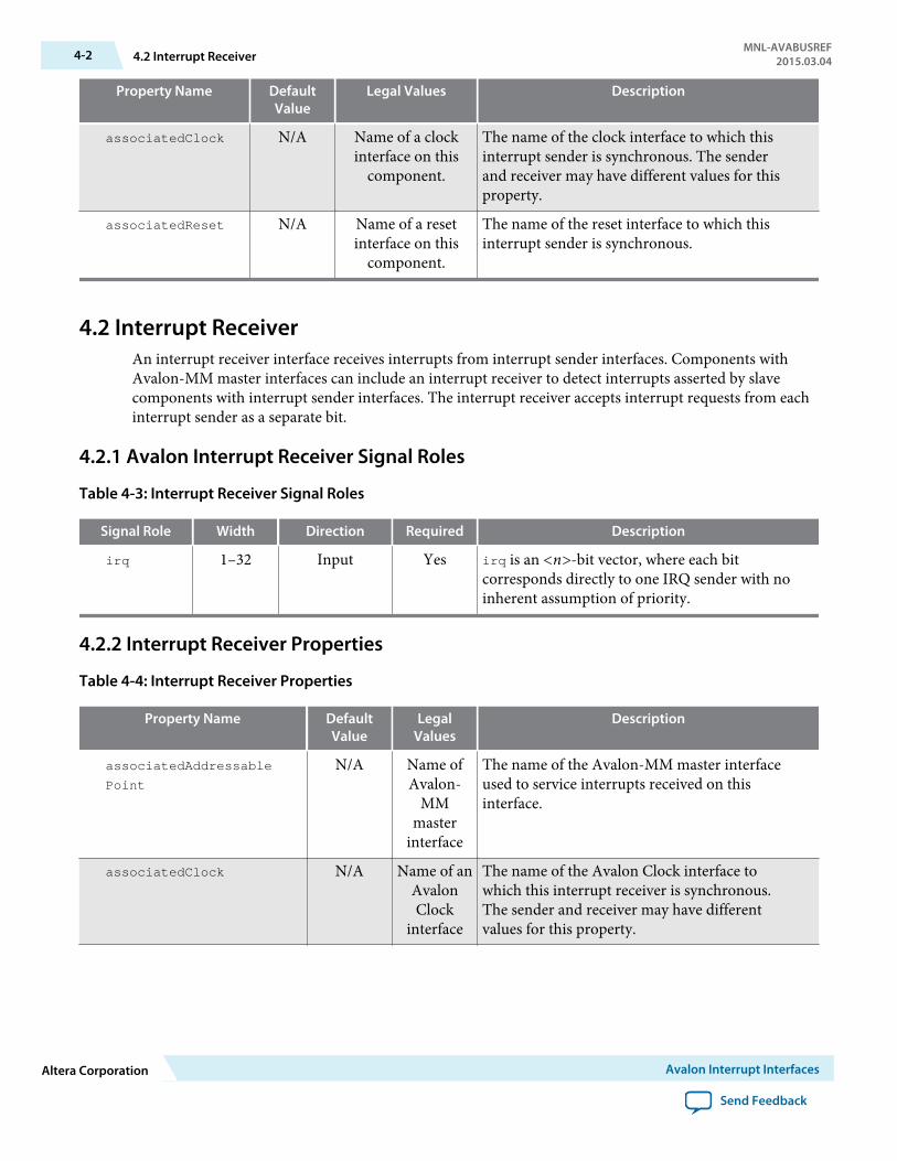
4.2 Interrupt ReceiverAn interrupt receiver interface receives interrupts from interrupt sender interfaces. Components withAvalon-MM master interfaces can include an interrupt receiver to detect interrupts asserted by slavecomponents with interrupt sender interfaces. The interrupt receiver accepts interrupt requests from eachinterrupt sender as a separate bit.
4.2.1 Avalon Interrupt Receiver Signal Roles
Table 4-3: Interrupt Receiver Signal Roles
Signal Role Width Direction Required Description
irq 1–32 Input Yes irq is an <n>-bit vector, where each bitcorresponds directly to one IRQ sender with noinherent assumption of priority.
4.2.2 Interrupt Receiver Properties
Table 4-4: Interrupt Receiver Properties
Property Name DefaultValue
LegalValues
Description
associatedAddressable
Point
N/A Name ofAvalon-
MMmaster
interface
The name of the Avalon-MM master interfaceused to service interrupts received on thisinterface.
associatedClock N/A Name of anAvalonClock
interface
The name of the Avalon Clock interface towhich this interrupt receiver is synchronous.The sender and receiver may have differentvalues for this property.
4-2 4.2 Interrupt ReceiverMNL-AVABUSREF
2015.03.04
Altera Corporation Avalon Interrupt Interfaces
Send Feedback

Property Name DefaultValue
LegalValues
Description
associatedReset N/A Name of anAvalonReset
interface
The name of the reset interface to which thisinterrupt receiver is synchronous.
4.2.3 Interrupt TimingThe Avalon-MM master services the priority 0 interrupt before the priority 1 interrupt.
Figure 4-1: Interrupt Timing
In the following figure, interrupt 0 has higher priority. The interrupt receiver is in the process of handlingint1 when int0 is asserted. The int0 handler is called and completes. Then, the int1 handler resumes.The diagram shows int0 deasserts at time 1. int1 deasserts at time 2.
clk
int0
int1
1 2
IndividualRequests
MNL-AVABUSREF2015.03.04 4.2.3 Interrupt Timing 4-3
Avalon Interrupt Interfaces Altera Corporation
Send Feedback
Avalon Streaming Interfaces 52015.03.04
MNL-AVABUSREF Subscribe Send Feedback
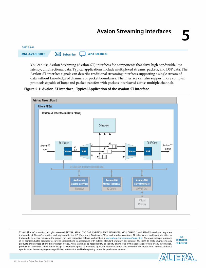
You can use Avalon Streaming (Avalon-ST) interfaces for components that drive high bandwidth, lowlatency, unidirectional data. Typical applications include multiplexed streams, packets, and DSP data. TheAvalon-ST interface signals can describe traditional streaming interfaces supporting a single stream ofdata without knowledge of channels or packet boundaries. The interface can also support more complexprotocols capable of burst and packet transfers with packets interleaved across multiple channels.
Figure 5-1: Avalon-ST Interface - Typical Application of the Avalon-ST Interface
SDRAMMemory
Avalon-MMMaster Interface
Processor
Avalon-MM Interface (Control Plane)
Avalon-MMMaster Interface
IO Control
Avalon-MMSlave Interface
SDRAM Cntl
Source Sink SinkSourcech 0-2
2
1
0
Scheduler
Tx IF CoreRx IF CoreAvalon-ST
InputAvalon-ST
Output
Avalon-ST Interfaces (Data Plane)
Altera FPGA
Printed Circuit Board
© 2015 Altera Corporation. All rights reserved. ALTERA, ARRIA, CYCLONE, ENPIRION, MAX, MEGACORE, NIOS, QUARTUS and STRATIX words and logos aretrademarks of Altera Corporation and registered in the U.S. Patent and Trademark Office and in other countries. All other words and logos identified astrademarks or service marks are the property of their respective holders as described at www.altera.com/common/legal.html. Altera warrants performanceof its semiconductor products to current specifications in accordance with Altera's standard warranty, but reserves the right to make changes to anyproducts and services at any time without notice. Altera assumes no responsibility or liability arising out of the application or use of any information,product, or service described herein except as expressly agreed to in writing by Altera. Altera customers are advised to obtain the latest version of devicespecifications before relying on any published information and before placing orders for products or services.
ISO9001:2008Registered
www.altera.com101 Innovation Drive, San Jose, CA 95134

All Avalon-ST source and sink interfaces are not necessarily interoperable. However, if two interfacesprovide compatible functions for the same application space, adapters are available to allow them tointeroperate.
Avalon-ST interfaces support datapaths requiring the following features:
• Low latency, high throughput point-to-point data transfer• Multiple channel support with flexible packet interleaving• Sideband signaling of channel, error, and start and end of packet delineation• Support for data bursting• Automatic interface adaptation
5.1 Terms and ConceptsThe Avalon-ST interface protocol defines the following terms and concepts:
• Avalon Streaming System—An Avalon Streaming system contains one or more Avalon-STconnections that transfer data from a source interface to a sink interface. The system shown aboveconsists of Avalon-ST interfaces to transfer data from the system input to output. Avalon-MM controland status register interfaces provide for software control.
• Avalon Streaming Components—A typical system using Avalon-ST interfaces combines multiplefunctional modules, called components. The system designer configures the components and connectsthem together to implement a system.
• Source and Sink Interfaces and Connections—When two components are connected, the data flowsfrom the source interface to the sink interface. The combination of a source interface connected to asink interface is referred to as a connection.
• Backpressure—Backpressure allows a sink to signal a source to stop sending data. Support forbackpressure is optional. The sink uses backpressure to stop the flow of data for the following reasons:
• When its FIFOs are full• When there is congestion on its output interface.
• Transfers and Ready Cycles—A transfer results in data and control propagation from a sourceinterface to a sink interface. For data interfaces, a ready cycle is a cycle during which the sink canaccept a transfer.
• Symbol—A symbol is the smallest unit of data. For most packet interfaces, a symbol is a byte. One ormore symbols make up the single unit of data transferred in a cycle.
• Channel—A channel is a physical or logical path or link through which information passes betweentwo ports.
• Beat—A beat is a single cycle transfer between a source and sync interface made up of one or moresymbols.
• Packet—A packet is an aggregation of data and control signals that is transmitted together. A packetmay contain a header to help routers and other network devices direct the packet to the correctdestination. The packet format is defined by the application, not this specification. Avalon-ST packetscan be variable in length and can be interleaved across a connection. With an Avalon-ST interfaces, theuse of packets is optional.
5-2 5.1 Terms and ConceptsMNL-AVABUSREF
2015.03.04
Altera Corporation Avalon Streaming Interfaces
Send Feedback

5.2 Avalon Streaming Interface Signal RolesEach signal in an Avalon-ST source or sink interface corresponds to one Avalon-ST signal role. AnAvalon-ST interface may contain only one instance of each signal role. All Avalon-ST signal roles apply toboth sources and sinks and have the same meaning for both.
Table 5-1: Avalon-ST Interface Signals
In the following table, all signal roles are active high.Signal Role Width Direction Description
Fundamental Signalschannel 1 – 128 Source → Sink The channel number for data being transferred
on the current cycle.
If an interface supports the channel signal, it mustalso define the maxChannel parameter.
data 1 – 4,096 Source → Sink The data signal from the source to the sink,typically carries the bulk of the information beingtransferred.
The contents and format of the data signal isfurther defined by parameters.
error 1 – 256 Source → Sink A bit mask used to mark errors affecting the databeing transferred in the current cycle. A single bitin error is used for each of the errors recognizedby the component, as defined by the errorDe-scriptor property.
ready 1 Sink → Source Asserted high to indicate that the sink can acceptdata. ready is asserted by the sink on cycle <n> tomark cycle <n + readyLatency> as a ready cycle.The source may only assert valid and transferdata during ready cycles.
Sources without a ready input cannot bebackpressured. Sinks without a ready outputnever need to backpressure.
valid 1 Source → Sink Asserted by the source to qualify all other sourceto sink signals. The sink samples data othersource-to-sink signals on ready cycles wherevalid is asserted. All other cycles are ignored.
Sources without a valid output implicitlyprovide valid data on every cycle that they are notbeing backpressured. Sinks without a valid inputexpect valid data on every cycle that they are notbackpressuring.
Packet Transfer Signals
MNL-AVABUSREF2015.03.04 5.2 Avalon Streaming Interface Signal Roles 5-3
Avalon Streaming Interfaces Altera Corporation
Send Feedback
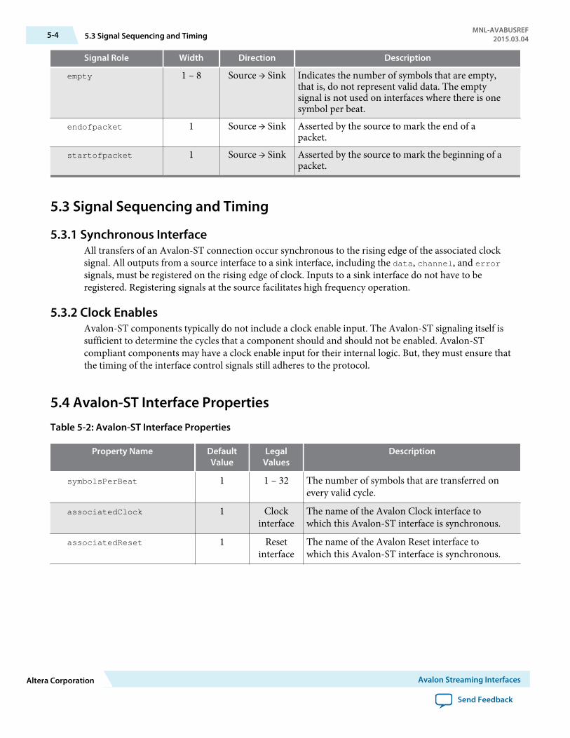
Signal Role Width Direction Description
empty 1 – 8 Source → Sink Indicates the number of symbols that are empty,that is, do not represent valid data. The emptysignal is not used on interfaces where there is onesymbol per beat.
endofpacket 1 Source → Sink Asserted by the source to mark the end of apacket.
startofpacket 1 Source → Sink Asserted by the source to mark the beginning of apacket.
5.3 Signal Sequencing and Timing
5.3.1 Synchronous InterfaceAll transfers of an Avalon-ST connection occur synchronous to the rising edge of the associated clocksignal. All outputs from a source interface to a sink interface, including the data, channel, and errorsignals, must be registered on the rising edge of clock. Inputs to a sink interface do not have to beregistered. Registering signals at the source facilitates high frequency operation.
5.3.2 Clock EnablesAvalon-ST components typically do not include a clock enable input. The Avalon-ST signaling itself issufficient to determine the cycles that a component should and should not be enabled. Avalon-STcompliant components may have a clock enable input for their internal logic. But, they must ensure thatthe timing of the interface control signals still adheres to the protocol.
5.4 Avalon-ST Interface Properties
Table 5-2: Avalon-ST Interface Properties
Property Name DefaultValue
LegalValues
Description
symbolsPerBeat 1 1 – 32 The number of symbols that are transferred onevery valid cycle.
associatedClock 1 Clockinterface
The name of the Avalon Clock interface towhich this Avalon-ST interface is synchronous.
associatedReset 1 Resetinterface
The name of the Avalon Reset interface towhich this Avalon-ST interface is synchronous.
5-4 5.3 Signal Sequencing and TimingMNL-AVABUSREF
2015.03.04
Altera Corporation Avalon Streaming Interfaces
Send Feedback

Property Name DefaultValue
LegalValues
Description
beatsPerCycle 8 Specifies the number of beats that aretransferred in a single cycle. This propertyallows you to transfer 2 separate, but correlatedstreams using the same start_of_packet,end_of_packet, ready and valid signals.
beatsPerCycle is a rarely used feature of theAvalon-ST protocol.
dataBitsPerSymbol 8 1 – 512 Defines the number of bits per symbol. Forexample, byte-oriented interfaces have 8-bitsymbols. This value is not restricted to be apower of 2.
emptyWithinPacket false true, false When true, empty is valid for the entire packet.
errorDescriptor 0 List ofstrings
A list of words that describe the errorassociated with each bit of the error signal. Thelength of the list must be the same as thenumber of bits in the error signal. The firstword in the list applies to the highest order bit.For example, “crc, overflow" means that bit[1]of error indicates a CRC error. Bit[0] indicatesan overflow error.
firstSymbolInHigh
OrderBits
true true, false When true, the first-order symbol is driven tothe most significant bits of the data interface.The highest-order symbol is labeled D0 in thisspecification. When this property is set to false,the first symbol appears on the low bits. D0appears at data[7:0]. For a 32-bit bus, if true,D0 appears on bits[31:24].
maxChannel 0 0 – 255 The maximum number of channels that a datainterface can support.
readyLatency 0 0 – 8 Defines the relationship between assertion anddeassertion of ready and cycles which areconsidered to be available for data transfer. ThereadyLatency is defined separately for eachinterface.
5.5 Typical Data TransfersThis section defines the transfer of data from a source interface to a sink interface. In all cases, the datasource and the data sink must comply with the specification. It is not the responsibility of the data sink todetect source protocol errors.
MNL-AVABUSREF2015.03.04 5.5 Typical Data Transfers 5-5
Avalon Streaming Interfaces Altera Corporation
Send Feedback
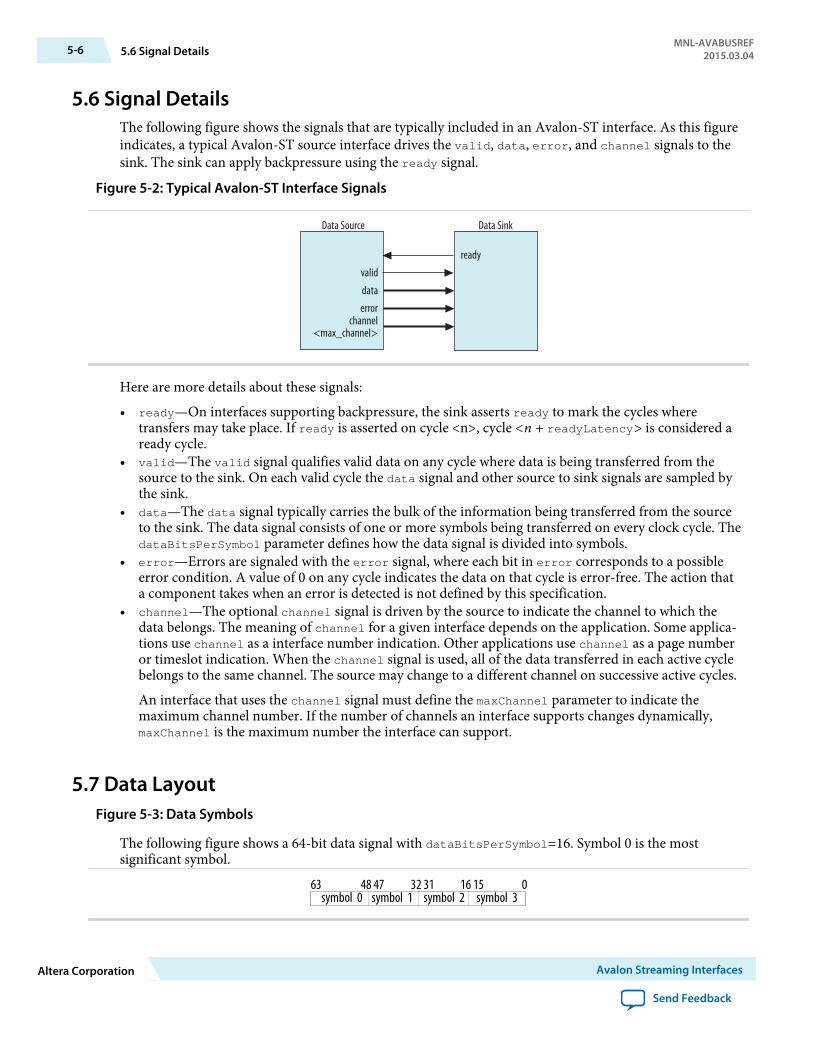
5.6 Signal DetailsThe following figure shows the signals that are typically included in an Avalon-ST interface. As this figureindicates, a typical Avalon-ST source interface drives the valid, data, error, and channel signals to thesink. The sink can apply backpressure using the ready signal.
Figure 5-2: Typical Avalon-ST Interface Signals
valid
data
error
ready
Data SinkData Source
channel<max_channel>
Here are more details about these signals:
• ready—On interfaces supporting backpressure, the sink asserts ready to mark the cycles wheretransfers may take place. If ready is asserted on cycle <n>, cycle <n + readyLatency> is considered aready cycle.
• valid—The valid signal qualifies valid data on any cycle where data is being transferred from thesource to the sink. On each valid cycle the data signal and other source to sink signals are sampled bythe sink.
• data—The data signal typically carries the bulk of the information being transferred from the sourceto the sink. The data signal consists of one or more symbols being transferred on every clock cycle. ThedataBitsPerSymbol parameter defines how the data signal is divided into symbols.
• error—Errors are signaled with the error signal, where each bit in error corresponds to a possibleerror condition. A value of 0 on any cycle indicates the data on that cycle is error-free. The action thata component takes when an error is detected is not defined by this specification.
• channel—The optional channel signal is driven by the source to indicate the channel to which thedata belongs. The meaning of channel for a given interface depends on the application. Some applica‐tions use channel as a interface number indication. Other applications use channel as a page numberor timeslot indication. When the channel signal is used, all of the data transferred in each active cyclebelongs to the same channel. The source may change to a different channel on successive active cycles.
An interface that uses the channel signal must define the maxChannel parameter to indicate themaximum channel number. If the number of channels an interface supports changes dynamically,maxChannel is the maximum number the interface can support.
5.7 Data LayoutFigure 5-3: Data Symbols
The following figure shows a 64-bit data signal with dataBitsPerSymbol=16. Symbol 0 is the mostsignificant symbol.
symbol 0 symbol 3symbol 2symbol 163 48 47 32 31 16 15 0
5-6 5.6 Signal DetailsMNL-AVABUSREF
2015.03.04
Altera Corporation Avalon Streaming Interfaces
Send Feedback
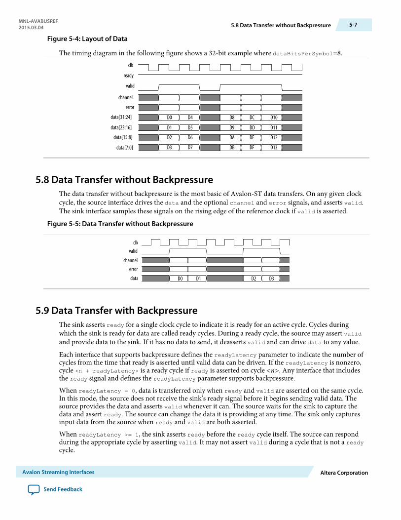
Figure 5-4: Layout of Data
The timing diagram in the following figure shows a 32-bit example where dataBitsPerSymbol=8.clk
ready
valid
channel
error
data[31:24]
data[23:16]
data[15:8]
data[7:0]
D0 D4 D8
D1
D2
D3
D5
D6
D7
D9
DA
DD
DC
DE
DF
D11
D12
DB
D10
D13
5.8 Data Transfer without BackpressureThe data transfer without backpressure is the most basic of Avalon-ST data transfers. On any given clockcycle, the source interface drives the data and the optional channel and error signals, and asserts valid.The sink interface samples these signals on the rising edge of the reference clock if valid is asserted.
Figure 5-5: Data Transfer without Backpressure
clkvalid
channel
error
data D1 D2 D3D0
5.9 Data Transfer with BackpressureThe sink asserts ready for a single clock cycle to indicate it is ready for an active cycle. Cycles duringwhich the sink is ready for data are called ready cycles. During a ready cycle, the source may assert validand provide data to the sink. If it has no data to send, it deasserts valid and can drive data to any value.
Each interface that supports backpressure defines the readyLatency parameter to indicate the number ofcycles from the time that ready is asserted until valid data can be driven. If the readyLatency is nonzero,cycle <n + readyLatency> is a ready cycle if ready is asserted on cycle <n>. Any interface that includesthe ready signal and defines the readyLatency parameter supports backpressure.
When readyLatency = 0, data is transferred only when ready and valid are asserted on the same cycle.In this mode, the source does not receive the sink’s ready signal before it begins sending valid data. Thesource provides the data and asserts valid whenever it can. The source waits for the sink to capture thedata and assert ready. The source can change the data it is providing at any time. The sink only capturesinput data from the source when ready and valid are both asserted.
When readyLatency >= 1, the sink asserts ready before the ready cycle itself. The source can respondduring the appropriate cycle by asserting valid. It may not assert valid during a cycle that is not a readycycle.
MNL-AVABUSREF2015.03.04 5.8 Data Transfer without Backpressure 5-7
Avalon Streaming Interfaces Altera Corporation
Send Feedback
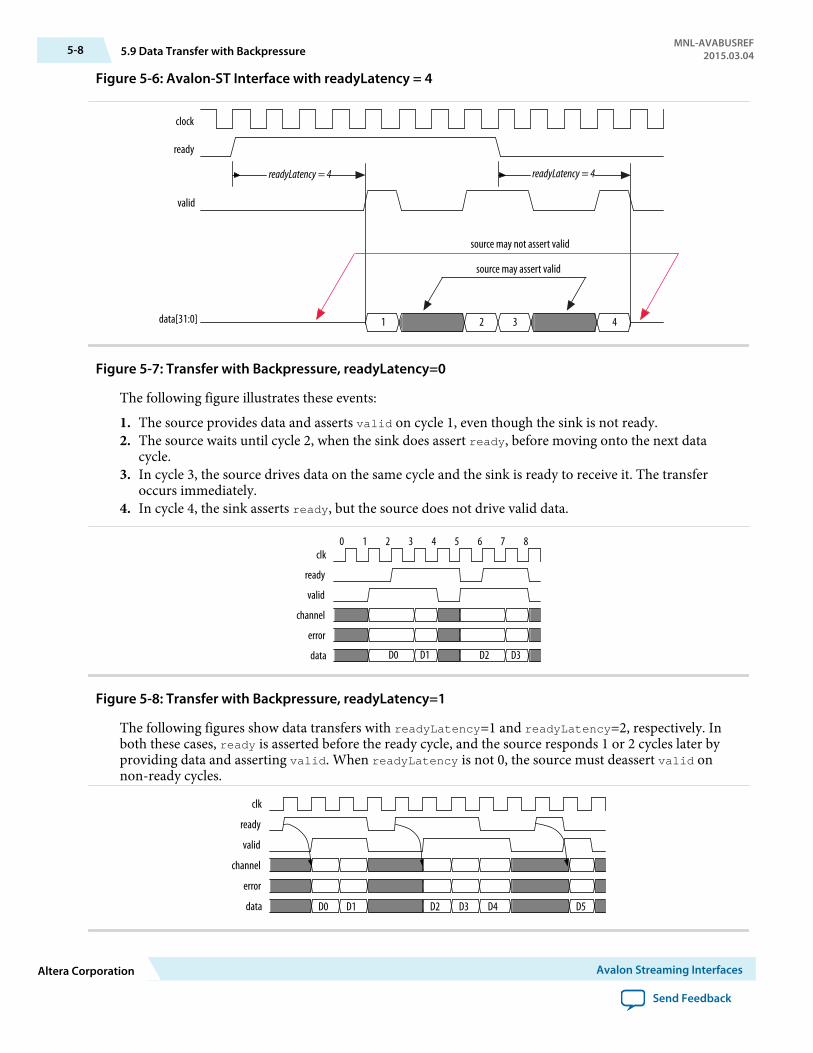
Figure 5-6: Avalon-ST Interface with readyLatency = 4
clock
ready
valid
data[31:0]
readyLatency = 4 readyLatency = 4
1 2 3 4
source may not assert valid
source may assert valid
Figure 5-7: Transfer with Backpressure, readyLatency=0
The following figure illustrates these events:
1. The source provides data and asserts valid on cycle 1, even though the sink is not ready.2. The source waits until cycle 2, when the sink does assert ready, before moving onto the next data
cycle.3. In cycle 3, the source drives data on the same cycle and the sink is ready to receive it. The transfer
occurs immediately.4. In cycle 4, the sink asserts ready, but the source does not drive valid data.
clk
ready
valid
channel
error
data
0 1 2 3 5 6 7 84
D0 D1 D2 D3
Figure 5-8: Transfer with Backpressure, readyLatency=1
The following figures show data transfers with readyLatency=1 and readyLatency=2, respectively. Inboth these cases, ready is asserted before the ready cycle, and the source responds 1 or 2 cycles later byproviding data and asserting valid. When readyLatency is not 0, the source must deassert valid onnon-ready cycles.
clk
ready
valid
channel
error
data D0 D1 D2 D3 D4 D5
5-8 5.9 Data Transfer with BackpressureMNL-AVABUSREF
2015.03.04
Altera Corporation Avalon Streaming Interfaces
Send Feedback
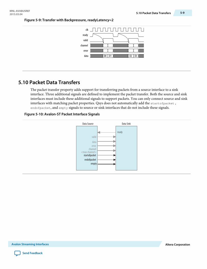
Figure 5-9: Transfer with Backpressure, readyLatency=2
clk
ready
valid
channel
error
data D0 D1 D2 D3
5.10 Packet Data TransfersThe packet transfer property adds support for transferring packets from a source interface to a sinkinterface. Three additional signals are defined to implement the packet transfer. Both the source and sinkinterfaces must include these additional signals to support packets. You can only connect source and sinkinterfaces with matching packet properties. Qsys does not automatically add the startofpacket ,endofpacket, and empty signals to source or sink interfaces that do not include these signals.
Figure 5-10: Avalon-ST Packet Interface Signals
channel<max channel>
valid
dataerror
ready
Data Source Data Sink
empty
startofpacketendofpacket
MNL-AVABUSREF2015.03.04 5.10 Packet Data Transfers 5-9
Avalon Streaming Interfaces Altera Corporation
Send Feedback

5.11 Signal Details• startofpacket—All interfaces supporting packet transfers require the startofpacket signal.
startofpacket marks the active cycle containing the start of the packet. This signal is only interpretedwhen valid is asserted.
• endofpacket—All interfaces supporting packet transfers require the endofpacket signal.endofpacket marks the active cycle containing the end of the packet. This signal is only interpretedwhen valid is asserted. startofpacket and endofpacket can be asserted in the same cycle. No idlecycles are required between packets. The startofpacket signal can follow immediately after theprevious endofpacket signal.
• empty—The optional empty signal indicates the number of symbols that are empty the endofpacketcycle. The sink only checks the value of the empty during active cycles that have endofpacket asserted.The empty symbols are always the last symbols in data, those carried by the low-order bits whenfirstSymbolInHighOrderBits = true. The empty signal is required on all packet interfaces whosedata signal carries more than one symbol of data and have a variable length packet format. The size ofthe empty signal in bits is log2(<symbols per cycle>) - 1.
5.12 Protocol DetailsPacket data transfer follows the same protocol as the typical data transfer with the addition of thestartofpacket, endofpacket, and empty.
Figure 5-11: Packet Transfer
The following figure illustrates the transfer of a 17-byte packet from a source interface to a sink interface,where readyLatency=0. It illustrates the following events:
1. Data transfer occurs on cycles 1, 2, 4, 5, and 6, when both ready and valid are asserted.2. During cycle 1, startofpacket is asserted. The first 4 bytes of packet are transferred.3. During cycle 6, endofpacket is asserted. empty has a value of 3. This value indicates that this is the end
of the packet and that 3 of the 4 symbols are empty. In cycle 6, the high-order byte, data[31:24] drivesvalid data.
clk
ready
valid
startofpacket
endofpacket
empty
channel
error
data[31:24]
data[23:16]
data[15:8]
data[7:0]
0 0 0 0 0
0 0 0 0 0
D0 D4 D8 D12 D16
D1 D5 D9 D13
D2 D6 D10 D14
D3 D7 D11 D15
3
1 2 3 4 5 6 7
5-10 5.11 Signal DetailsMNL-AVABUSREF
2015.03.04
Altera Corporation Avalon Streaming Interfaces
Send Feedback

Avalon Conduit Interfaces 62015.03.04
MNL-AVABUSREF Subscribe Send Feedback
Avalon Conduit interfaces group an arbitrary collection of signals. You can specify any role for conduitsignals. However, when you connect conduits, the roles and widths must match and the directions mustbe opposite. An Avalon Conduit interface can include input, output, and bidirectional signals. A modulecan have multiple Avalon Conduit interfaces to provide a logical signal grouping. Conduit interfaces candeclare an associated clock. When connected conduit interfaces are in different clock domains, Qsysgenerates an error message.
Note: If possible, you should use the standard Avalon-MM or Avalon-ST interfaces instead of creating anAvalon Conduit interface. Qsys provides validation and adaptation for these interfaces. It cannotprovide validation or adaptation for Avalon Conduit interfaces.
Conduit interfaces typically used to drive off-chip device signals, such as an SDRAM address, data andcontrol signals.
© 2015 Altera Corporation. All rights reserved. ALTERA, ARRIA, CYCLONE, ENPIRION, MAX, MEGACORE, NIOS, QUARTUS and STRATIX words and logos aretrademarks of Altera Corporation and registered in the U.S. Patent and Trademark Office and in other countries. All other words and logos identified astrademarks or service marks are the property of their respective holders as described at www.altera.com/common/legal.html. Altera warrants performanceof its semiconductor products to current specifications in accordance with Altera's standard warranty, but reserves the right to make changes to anyproducts and services at any time without notice. Altera assumes no responsibility or liability arising out of the application or use of any information,product, or service described herein except as expressly agreed to in writing by Altera. Altera customers are advised to obtain the latest version of devicespecifications before relying on any published information and before placing orders for products or services.
ISO9001:2008Registered
www.altera.com101 Innovation Drive, San Jose, CA 95134

Figure 6-1: Focus on the Conduit Interface
Avalon-MM System
System Interconnect Fabric
EthernetPHY
AvalonSlave
Avalon-MMSlave
SDRAMMemory
Avalon-MMMaster
Processor
Avalon-MMMaster
Avalon-MMMaster
Ethernet MAC Custom Logic
SDRAMController
CustomLogic
ConduitInterface
CustomLogic
6.1 Avalon Conduit Signal Roles
Table 6-1: Conduit Signal Roles
Signal Role Width Direction Description
<any> <n> In, out, orbidirectional
A conduit interface consists of one or more input, output, orbidirectional signals of arbitrary width. Conduits can have anyuser-specified role. You can connect compatible Conduitinterfaces inside a Qsys system provided the roles and widthsmatch and the directions are opposite.
6.2 Conduit PropertiesThere are no properties for conduit interfaces.
6-2 6.1 Avalon Conduit Signal RolesMNL-AVABUSREF
2015.03.04
Altera Corporation Avalon Conduit Interfaces
Send Feedback

Avalon Tristate Conduit Interface 72015.03.04
MNL-AVABUSREF Subscribe Send Feedback
The Avalon Tristate Conduit Interface (Avalon-TC) is a point-to-point interface designed for on-chipcontrollers that drive off-chip components. This interface allows data, address, and control pins to beshared across multiple tristate devices. Sharing conserves pins in systems that have multiple externalmemory devices.
The Avalon-TC interface restricts the more general Avalon Conduit Interface in two ways:
• The Avalon-TC requires request and grant signals. These signals enable bus arbitration whenmultiple Tristate Conduit Masters (TCM) are requesting access to a shared bus.
• The pin type of a signal must be specified using suffixes appended to a signal’s role. The three suffixesare: _out, _in, and _outen. Matching role prefixes identify signals that share the same I/O Pin. Thefollowing illustrates the naming conventions for Avalon-TC shared pins.
Figure 7-1: Shared Pin Types
data_out datadata_in
data_outen
Altera FPGABidirectional Pin
busy_in busy
Altera FPGAInput Only Pin
reset_out reset
Altera FPGATri-State Output Only Pin
reset_outen ~reset
Altera FPGAOutput Only Pin
write_out write
The next figure illustrates pin sharing using Avalon-TC interfaces. This figure illustrates the followingpoints.
© 2015 Altera Corporation. All rights reserved. ALTERA, ARRIA, CYCLONE, ENPIRION, MAX, MEGACORE, NIOS, QUARTUS and STRATIX words and logos aretrademarks of Altera Corporation and registered in the U.S. Patent and Trademark Office and in other countries. All other words and logos identified astrademarks or service marks are the property of their respective holders as described at www.altera.com/common/legal.html. Altera warrants performanceof its semiconductor products to current specifications in accordance with Altera's standard warranty, but reserves the right to make changes to anyproducts and services at any time without notice. Altera assumes no responsibility or liability arising out of the application or use of any information,product, or service described herein except as expressly agreed to in writing by Altera. Altera customers are advised to obtain the latest version of devicespecifications before relying on any published information and before placing orders for products or services.
ISO9001:2008Registered
www.altera.com101 Innovation Drive, San Jose, CA 95134

• The Tristate Conduit Pin Sharer includes separate Tristate Conduit Slave Interfaces for each TristateConduit Master. Each master and slave pair has its own request and grant signals.
• The Tristate Conduit Pin Sharer identifies signals with identical roles as tristate signals that share thesame FPGA pin. In this example, the following signals are shared: addr_out, data_out, data_in,read_out, and write_out.
• The Tristate Conduit Pin Sharer drives a single bus including all of the shared signals to the TristateConduit Bridge. If the widths of shared signals differ, the Tristate Conduit Pin Sharer aligns them ontheir 0th bit. It drives the higher-order pins to 0 whenever the smaller signal has control of the bus.
• Signals that are not shared propagate directly through the Tristate Conduit Pin Sharer. In this example,the following signals are not shared: chipselect0_out, irq0_out, chipselect1_out, and irq1_out.
• All Avalon-TC interfaces connected to the same Tristate Conduit Pin Sharer must be in the same clockdomain.
7-2 Avalon Tristate Conduit InterfaceMNL-AVABUSREF
2015.03.04
Altera Corporation Avalon Tristate Conduit Interface
Send Feedback
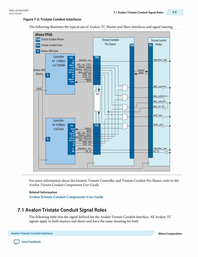
Figure 7-2: Tristate Conduit Interfaces
The following illustrates the typical use of Avalon-TC Master and Slave interfaces and signal naming.
Altera FPGA
TCM
Tristate ConduitPin Sharer TCS
Tristate ConduitBridge
S
Controller for 2 MBytex32 SSRAM
CSIRQ
A[20:0]D_EN
D[31:0]DI[31:0]
RdWr
RequestGrant
TCM
S
GrantReq
A[22:0]D_EN
D[15:0]DI[15:0]
RdWr
TCM
chipselect_out
dataout_outendataout_out[31:0]
data_in[31:0]read_outwrite_out
requestgrant
requestgrant
addr_out_[20:0]
chipselect_outirq_in
Controller for 8 MByte
x16 Flash
addr_out<n>
data_out<n>
data_in<n>
data_outen<n>
chipselect_out
requestgrant
irq_inchipselect_out
write_out
read_out
clock
Avalon-MM Master
TCS
TCS
CSIRQ
Avalon-MM SlaveS
TCM Tristate Conduit Master
Tristate Conduit SlaveTCS
Arb
dataout_outendataout_out[15:0]
data_in[15:0]read_outwrite_out
addr_out_[22:0]
For more information about the Generic Tristate Controller and Tristate Conduit Pin Sharer, refer to theAvalon Tristate Conduit Components User Guide.
Related InformationAvalon Tristate Conduit Components User Guide
7.1 Avalon Tristate Conduit Signal RolesThe following table lists the signal defined for the Avalon Tristate Conduit interface. All Avalon-TCsignals apply to both masters and slaves and have the same meaning for both
MNL-AVABUSREF2015.03.04 7.1 Avalon Tristate Conduit Signal Roles 7-3
Avalon Tristate Conduit Interface Altera Corporation
Send Feedback
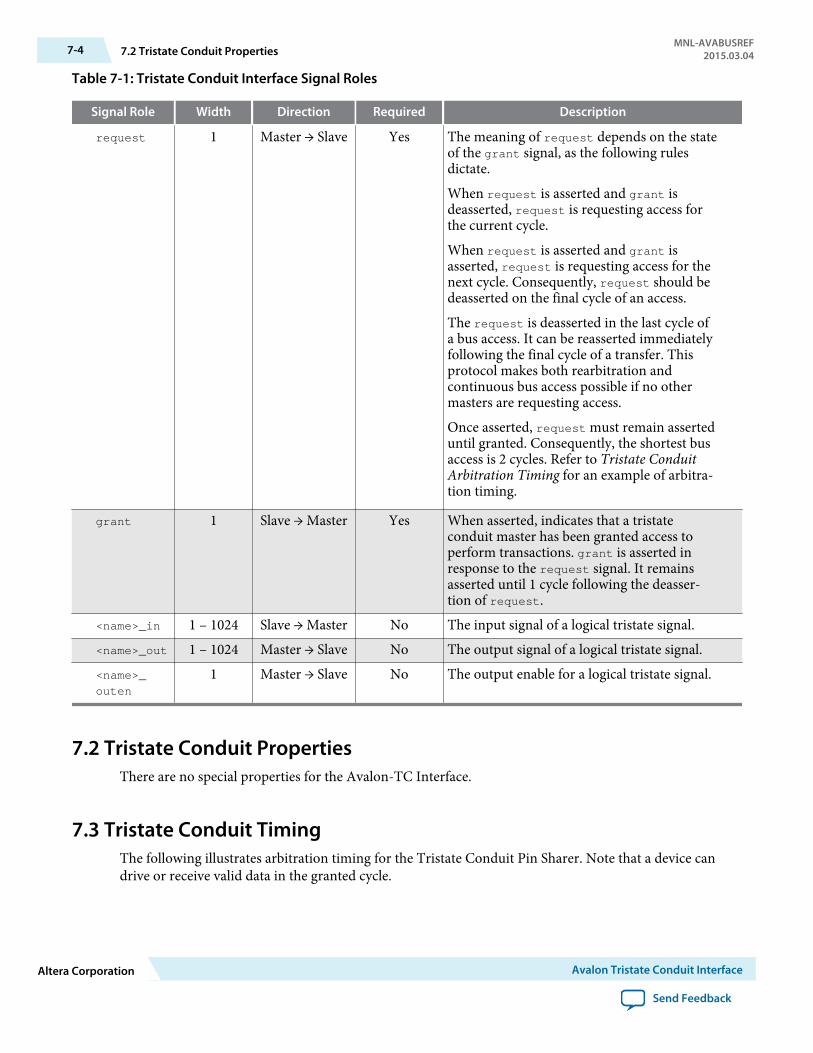
Table 7-1: Tristate Conduit Interface Signal Roles
Signal Role Width Direction Required Description
request 1 Master → Slave Yes The meaning of request depends on the stateof the grant signal, as the following rulesdictate.
When request is asserted and grant isdeasserted, request is requesting access forthe current cycle.
When request is asserted and grant isasserted, request is requesting access for thenext cycle. Consequently, request should bedeasserted on the final cycle of an access.
The request is deasserted in the last cycle ofa bus access. It can be reasserted immediatelyfollowing the final cycle of a transfer. Thisprotocol makes both rearbitration andcontinuous bus access possible if no othermasters are requesting access.
Once asserted, request must remain asserteduntil granted. Consequently, the shortest busaccess is 2 cycles. Refer to Tristate ConduitArbitration Timing for an example of arbitra‐tion timing.
grant 1 Slave → Master Yes When asserted, indicates that a tristateconduit master has been granted access toperform transactions. grant is asserted inresponse to the request signal. It remainsasserted until 1 cycle following the deasser‐tion of request.
<name>_in 1 – 1024 Slave → Master No The input signal of a logical tristate signal.<name>_out 1 – 1024 Master → Slave No The output signal of a logical tristate signal.<name>_
outen
1 Master → Slave No The output enable for a logical tristate signal.
7.2 Tristate Conduit PropertiesThere are no special properties for the Avalon-TC Interface.
7.3 Tristate Conduit TimingThe following illustrates arbitration timing for the Tristate Conduit Pin Sharer. Note that a device candrive or receive valid data in the granted cycle.
7-4 7.2 Tristate Conduit PropertiesMNL-AVABUSREF
2015.03.04
Altera Corporation Avalon Tristate Conduit Interface
Send Feedback

Figure 7-3: Tristate Conduit Arbitration Timing
This figure shows the following sequence of events:
1. In cycle 1, the tristate conduit slave asserts grant. The slave drives valid data in cycles1 and 2.2. In cycle 4, the tristate conduit slave asserts grant. The slave drives valid data in cycles 5–8.3. In cycle 9, the tristate conduit slave asserts grant. The slave drives valid data in cycles 10–17.4. Cycles 3, 4 and 9 do not contain valid data.
clk
request
grant
data_out[31:0] 0 a b c d e f 10 11 12 13 14 15 16 17
1 3 62 74 5 8 10 139 1411 12 16 1715
.
MNL-AVABUSREF2015.03.04 7.3 Tristate Conduit Timing 7-5
Avalon Tristate Conduit Interface Altera Corporation
Send Feedback
Deprecated Signals A2015.03.04
MNL-AVABUSREF Subscribe Send Feedback
Deprecated signals implement functionality that is no longer required or has been superceded.
begintransfer
An output of Avalon-MM masters. Asserted for a single cycle at the beginning of a transfer. This is signalis not used and not necessary.
chipselect or chipselect_n
chipselect or chipselect_n: The chip select signal as described below was deprecated with the releaseof the Avalon Tristate Conduct (Avalon-TC) interface type which includes a chip select signal.
Formerally chipselect was a 1-bit input to an Avalon Memory-Mapped (Avalon-MM) slave interfacesignalling the beginning of a read or write transfer. The current Qsys interconnect filters read and writesignals from masters according to the address and address map. The Qsys interconnect only drives readand write signals to the appropriate Avalon-MM slave, making a chip select unnecessary.
This signal dates from very early microprocessor designs. CPLDs decoded microprocessor addresses andgenerated chip selects for peripherals that typically were frequently asynchronous. With synchronoussystems this signal is typically unnecessary.
flush
This signal was removed version 1.2 of the Avalon Interface Specifications. Formerly available to mastersto clear pending transfers for pipelined reads.
© 2015 Altera Corporation. All rights reserved. ALTERA, ARRIA, CYCLONE, ENPIRION, MAX, MEGACORE, NIOS, QUARTUS and STRATIX words and logos aretrademarks of Altera Corporation and registered in the U.S. Patent and Trademark Office and in other countries. All other words and logos identified astrademarks or service marks are the property of their respective holders as described at www.altera.com/common/legal.html. Altera warrants performanceof its semiconductor products to current specifications in accordance with Altera's standard warranty, but reserves the right to make changes to anyproducts and services at any time without notice. Altera assumes no responsibility or liability arising out of the application or use of any information,product, or service described herein except as expressly agreed to in writing by Altera. Altera customers are advised to obtain the latest version of devicespecifications before relying on any published information and before placing orders for products or services.
ISO9001:2008Registered
www.altera.com101 Innovation Drive, San Jose, CA 95134
Additional Information B2015.03.04
MNL-AVABUSREF Subscribe Send Feedback
Table B-1: Document Revision History
Date Version Changes
March 2015 14.1 Fixed typo in Figure 1-1.
January 2015 14.1 Made the following changes:
• Clarified address alignment example. The Avalon-MM masterand slave interfaces are different widths.
• Improved discussion of Pipelined read Transfers with VariableLatency. Corrected timing marker 2 which should be exactlyon the rising edge of clock.
• Improved discussion of Pipelined Read Transfer with FixedLatency of Two Cycles.
• Clarified use of beatsPerCycle property.• Corrected the address range for line-wrapped bursts. The
correct address range for a 64-byte burst is 0x0–0x3C, not0x0–0x1C.
• Corrected description of the Tristate Conduit ArbitrationTiming diagram in the following ways:
• The tristate conduit slave asserts grant, not the tristateconduit master.
• The final grant comes in cycle 9, not cycle 8.• Added a Deprecated Signals appendix.• Added read response signal.• Improved definitions of clock and reset signal types.• Corrected definition of clock sink properties.• Corrected definition of synchronousEdges for reset source
interface.• Clarified the Avalon-MM response signal type.• Updated definition of empty. The signal must be interpreted
emptyWithinPacket is true.• Edited for clarity and consistency.
© 2015 Altera Corporation. All rights reserved. ALTERA, ARRIA, CYCLONE, ENPIRION, MAX, MEGACORE, NIOS, QUARTUS and STRATIX words and logos aretrademarks of Altera Corporation and registered in the U.S. Patent and Trademark Office and in other countries. All other words and logos identified astrademarks or service marks are the property of their respective holders as described at www.altera.com/common/legal.html. Altera warrants performanceof its semiconductor products to current specifications in accordance with Altera's standard warranty, but reserves the right to make changes to anyproducts and services at any time without notice. Altera assumes no responsibility or liability arising out of the application or use of any information,product, or service described herein except as expressly agreed to in writing by Altera. Altera customers are advised to obtain the latest version of devicespecifications before relying on any published information and before placing orders for products or services.
ISO9001:2008Registered
www.altera.com101 Innovation Drive, San Jose, CA 95134

Date Version Changes
June 2014 14.0 • Updated the Avalon-MM Signals table, begintransfer,readdatavalid, and readdatavalid_n.
• Updated the Read and Write Transfers with Waitrequestfigure:
• Moved deassertion of write to cycle 6.• Moved assertion of readdatavalid and readdata to cycle
4.• Updated the Pipelined Read Transfers with Variable Latency
figure:
• Moved assertion of data1 to just after cycle 5, andassertion of data2 to cycle 6.
• Moved assertion of readdatavalid to match data1 anddata2.
April 2014 13.01 Corrected Read and Write Transfers with Waitrequest In AvalonMemory-Mapped Interfaces chapter .
May 2013 13.0 Made the following changes:
• Minor updates to Avalon Memory-Mapped Interfaces.• Minor updates to Avalon Streaming Interfaces.• Updated Avalon Conduit Interfaces to describe the signal roles
supported by Avalon conduit interfaces.• Updated Shared Pin Types figure in the Avalon Tristate
Conduit Interface chapter.
May 2011 11.0 Initial release of the Avalon Interface Specifications supported byQsys.
B.1 How to Contact AlteraTo locate the most up-to-date information about Altera products, refer to the following table.
Table B-2: Altera Contact Information
Contact (1) Contact Method Address
Technical support Website www.altera.com/support
Technical trainingWebsite www.altera.com/training
Email [email protected]
Product literature Website www.altera.com/literature
B-2 B.1 How to Contact AlteraMNL-AVABUSREF
2015.03.04
Altera Corporation Additional Information
Send Feedback

Contact (1) Contact Method Address
Nontechnical support (general) Email [email protected]
Nontechnical support (softwarelicensing)
Email [email protected]
Note to Table:
1. You can also contact your local Altera sales office or sales representative.
Related Information
• www.altera.com/support• www.altera.com/training• [email protected]• www.altera.com/literature• [email protected]• [email protected]
B.2 Typographic ConventionsThe following table shows the typographic conventions this document uses.
Visual Cue Meaning
Bold Type with InitialCapital Letters
Indicate command names, dialog box titles, dialog box options, andother GUI labels. For example, Save As dialog box. For GUIelements, capitalization matches the GUI.
bold type Indicates directory names, project names, disk drive names, filenames, file name extensions, software utility names, and GUI labels.For example, \qdesigns directory, D: drive, and chiptrip.gdf file.
Italic Type with InitialCapital Letters
Indicate document titles. For example, Stratix IV Design Guidelines.
italic type Indicates variables. For example, n + 1.
Variable names are enclosed in angle brackets (< >). For example,<file name> and <project name>.pof file.
Initial Capital Letters Indicate keyboard keys and menu names. For example, the Deletekey and the Options menu.
“Subheading Title” Quotation marks indicate references to sections within a documentand titles of Quartus II Help topics. For example, “TypographicConventions.”
MNL-AVABUSREF2015.03.04 B.2 Typographic Conventions B-3
Additional Information Altera Corporation
Send Feedback
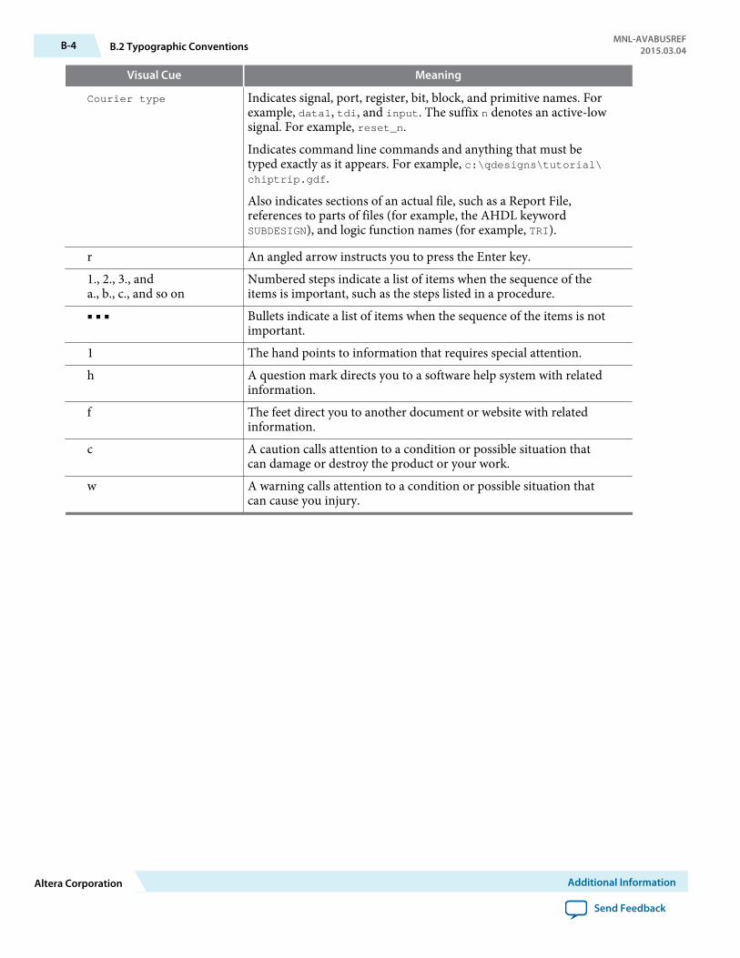
Visual Cue Meaning
Courier type Indicates signal, port, register, bit, block, and primitive names. Forexample, data1, tdi, and input. The suffix n denotes an active-lowsignal. For example, reset_n.
Indicates command line commands and anything that must betyped exactly as it appears. For example, c:\qdesigns\tutorial\chiptrip.gdf.
Also indicates sections of an actual file, such as a Report File,references to parts of files (for example, the AHDL keywordSUBDESIGN), and logic function names (for example, TRI).
r An angled arrow instructs you to press the Enter key.1., 2., 3., anda., b., c., and so on
Numbered steps indicate a list of items when the sequence of theitems is important, such as the steps listed in a procedure.
■ ■ ■ Bullets indicate a list of items when the sequence of the items is notimportant.
1 The hand points to information that requires special attention.h A question mark directs you to a software help system with related
information.f The feet direct you to another document or website with related
information.c A caution calls attention to a condition or possible situation that
can damage or destroy the product or your work.w A warning calls attention to a condition or possible situation that
can cause you injury.
B-4 B.2 Typographic ConventionsMNL-AVABUSREF
2015.03.04
Altera Corporation Additional Information
Send Feedback


