92
Release 2.0 555-233-758 Issue 6 November 2003 Avaya Communication Manager Little Instruction Book for Basic Diagnostics
Release 2.0555-233-758
Issue 6November 2003
Avaya Communication Manager
Little Instruction Book
for Basic Diagnostics
233758_6.book Page 1 Tuesday, August 5, 2003 6:22 AM
Copyright 2003, Avaya Inc.All Rights Reserved
Notice
Every effort was made to ensure that the information in this document was complete and accurate at the time of printing. However, information is subject to change.
Warranty
Avaya Inc. provides a limited warranty on this product. Refer to your sales agreement to establish the terms of the limited warranty. In addition, Avaya’s standard warranty language as well as information regarding support for this product, while under warranty, is available through the following Web site:http://www.avaya.com/support.
Preventing Toll Fraud
“Toll fraud” is the unauthorized use of your telecommunications system by an unauthorized party (for example, a person who is not a corporate employee, agent, subcontractor, or is not working on your company's behalf). Be aware that there may be a risk of toll fraud associated with your system and that, if toll fraud occurs, it can result in substantial additional charges for your telecommunications services.
Avaya Fraud Intervention
If you suspect that you are being victimized by toll fraud and you need technical assistance or support, in the United States and Canada, call the Technical Service Center's Toll Fraud Intervention Hotline at 1-800-643-2353.
How to Get Help
For additional support telephone numbers, go to the Avaya support Web site: http://www.avaya.com/support.
If you are:
• Within the United States, click the Escalation Management link. Then click the appropriate link for the type of support you need.
• Outside the United States, click the Escalation Management link. Then click the International Services link that includes telephone numbers for the international Centers of Excellence.
Providing Telecommunications Security
Telecommunications security (of voice, data, and/or video communications) is the prevention of any type of intrusion to (that is, either unauthorized or malicious access to or use of) your company's telecommunications equipment by some party.
Your company's “telecommunications equipment” includes both this Avaya product and any other voice/data/video equipment that could be accessed via this Avaya product (that is, “networked equipment”).
An “outside party” is anyone who is not a corporate employee, agent, subcontractor, or is not working on your company's behalf. Whereas, a “malicious party” is anyone (including someone who may be otherwise authorized) who accesses your telecommunications equipment with either malicious or mischievous intent.
233758_6.book Page 2 Tuesday, August 5, 2003 6:22 AM
Such intrusions may be either to/through synchronous (time-multiplexed and/or circuit-based) or asynchronous (character-, message-, or packet-based) equipment or interfaces for reasons of:
• Utilization (of capabilities special to the accessed equipment)• Theft (such as, of intellectual property, financial assets, or toll facility access)• Eavesdropping (privacy invasions to humans)• Mischief (troubling, but apparently innocuous, tampering)• Harm (such as harmful tampering, data loss or alteration, regardless of motive or intent)
Be aware that there may be a risk of unauthorized intrusions associated with your system and/or its networked equipment. Also realize that, if such an intrusion should occur, it could result in a variety of losses to your company (including but not limited to, human/data privacy, intellectual property, material assets, financial resources, labor costs, and/or legal costs).
Responsibility for Your Company’s Telecommunications Security
The final responsibility for securing both this system and its networked equipment rests with you - Avaya’s customer system administrator, your telecommunications peers, and your managers. Base the fulfillment of your responsibility on acquired knowledge and resources from a variety of sources including but not limited to:
• Installation documents• System administration documents• Security documents• Hardware-/software-based security tools• Shared information between you and your peers• Telecommunications security experts
To prevent intrusions to your telecommunications equipment, you and your peers should carefully program and configure:
• Your Avaya-provided telecommunications systems and their interfaces• Your Avaya-provided software applications, as well as their underlying hardware/software
platforms and interfaces• Any other equipment networked to your Avaya products
TCP/IP Facilities
Customers may experience differences in product performance, reliability and security depending upon network configurations/design and topologies, even when the product performs as warranted.
Standards Compliance
Avaya Inc. is not responsible for any radio or television interference caused by unauthorized modifications of this equipment or the substitution or attachment of connecting cables and equipment other than those specified by Avaya Inc. The correction of interference caused by such unauthorized modifications, substitution or attachment will be the responsibility of the user. Pursuant to Part 15 of the Federal Communications Commission (FCC) Rules, the user is cautioned that changes or modifications not expressly approved by Avaya Inc. could void the user’s authority to operate this equipment.
233758_6.book Page 3 Tuesday, August 5, 2003 6:22 AM
Product Safety Standards
This product complies with and conforms to the following international Product Safety standards as applicable:
Safety of Information Technology Equipment, IEC 60950, 3rd Edition including all relevant national deviations as listed in Compliance with IEC for Electrical Equipment (IECEE) CB-96A.
Safety of Information Technology Equipment, CAN/CSA-C22.2No. 60950-00 / UL 60950, 3rd Edition
Safety Requirements for Customer Equipment, ACA Technical Standard (TS) 001 - 1997
One or more of the following Mexican national standards, as applicable: NOM 001 SCFI 1993, NOM SCFI 016 1993, NOM 019 SCFI 1998
The equipment described in this document may contain Class 1 LASER Device(s). These devices comply with the following standards:
• EN 60825-1, Edition 1.1, 1998-01• 21 CFR 1040.10 and CFR 1040.11.
The LASER devices operate within the following parameters:
• Maximum power output: -5 dBm to -8 dBm• Center Wavelength: 1310 nm to 1360 nm
Luokan 1 LaserlaiteKlass 1 Laser Apparat
Use of controls or adjustments or performance of procedures other than those specified herein may result in hazardous radiation exposures. Contact your Avaya representative for more laser product information.
Electromagnetic Compatibility (EMC) Standards
This product complies with and conforms to the following international EMC standards and all relevant national deviations:
Limits and Methods of Measurement of Radio Interference of Information Technology Equipment, CISPR 22:1997 and EN55022:1998.
Information Technology Equipment – Immunity Characteristics – Limits and Methods of Measurement, CISPR 24:1997 and EN55024:1998, including:
• Electrostatic Discharge (ESD) IEC 61000-4-2• Radiated Immunity IEC 61000-4-3• Electrical Fast Transient IEC 61000-4-4• Lightning Effects IEC 61000-4-5• Conducted Immunity IEC 61000-4-6• Mains Frequency Magnetic Field IEC 61000-4-8• Voltage Dips and Variations IEC 61000-4-11• Powerline Harmonics IEC 61000-3-2• Voltage Fluctuations and Flicker IEC 61000-3-3
233758_6.book Page 4 Tuesday, August 5, 2003 6:22 AM
Federal Communications Commission Statement
Part 15:
Part 68: Answer-Supervision Signaling
Allowing this equipment to be operated in a manner that does not provide proper answer-supervision signaling is in violation of Part 68 rules. This equipment returns answer-supervision signals to the public switched network when:
• answered by the called station,• answered by the attendant, or• routed to a recorded announcement that can be administered by the customer premises equipment
(CPE) user.
This equipment returns answer-supervision signals on all direct inward dialed (DID) calls forwarded back to the public switched telephone network. Permissible exceptions are:
• A call is unanswered.• A busy tone is received.• A reorder tone is received.
Avaya attests that this registered equipment is capable of providing users access to interstate providers of operator services through the use of access codes. Modification of this equipment by call aggregators to block access dialing codes is a violation of the Telephone Operator Consumers Act of 1990.
REN Number
For MCC1, SCC1, CMC1, G600, and G650 Media Gateways:
This equipment complies with Part 68 of the FCC rules. On either the rear or inside the front cover of this equipment is a label that contains, among other information, the FCC registration number, and ringer equivalence number (REN) for this equipment. If requested, this information must be provided to the telephone company.
For G350 and G700 Media Gateways:
This equipment complies with Part 68 of the FCC rules and the requirements adopted by the ACTA. On the rear of this equipment is a label that contains, among other information, a product identifier in the format US:AAAEQ##TXXXX. The digits represented by ## are the ringer equivalence number (REN) without a decimal point (for example, 03 is a REN of 0.3). If requested, this number must be provided to the telephone company.
Note: This equipment has been tested and found to comply with the limits for a Class A digital device, pursuant to Part 15 of the FCC Rules. These limits are designed to provide reasonable protection against harmful interference when the equipment is operated in a commercial environment. This equipment generates, uses, and can radiate radio frequency energy and, if not installed and used in accordance with the instruction manual, may cause harmful interference to radio communications. Operation of this equipment in a residential area is likely to cause harmful interference in which case the user will be required to correct the interference at his own expense.
233758_6.book Page 5 Tuesday, August 5, 2003 6:22 AM
The REN is used to determine the quantity of devices that may be connected to the telephone line. Excessive RENs on the telephone line may result in devices not ringing in response to an incoming call. In most, but not all areas, the sum of RENs should not exceed 5.0. To be certain of the number of devices that may be connected to a line, as determined by the total RENs, contact the local telephone company.
REN is not required for some types of analog or digital facilities.
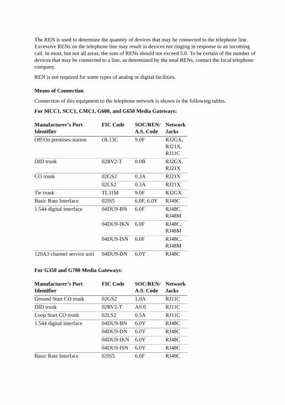
Means of Connection
Connection of this equipment to the telephone network is shown in the following tables.
For MCC1, SCC1, CMC1, G600, and G650 Media Gateways:
For G350 and G700 Media Gateways:
Manufacturer’s PortIdentifier
FIC Code SOC/REN/A.S. Code
Network Jacks
Off/On premises station OL13C 9.0F RJ2GX, RJ21X, RJ11C
DID trunk 02RV2-T 0.0B RJ2GX, RJ21X
CO trunk 02GS2 0.3A RJ21X
02LS2 0.3A RJ21X
Tie trunk TL31M 9.0F RJ2GX
Basic Rate Interface 02IS5 6.0F, 6.0Y RJ49C
1.544 digital interface 04DU9-BN 6.0F RJ48C, RJ48M
04DU9-IKN 6.0F RJ48C, RJ48M
04DU9-ISN 6.0F RJ48C, RJ48M
120A3 channel service unit 04DU9-DN 6.0Y RJ48C
Manufacturer’s PortIdentifier
FIC Code SOC/REN/A.S. Code
Network Jacks
Ground Start CO trunk 02GS2 1.0A RJ11C
DID trunk 02RV2-T AS.0 RJ11C
Loop Start CO trunk 02LS2 0.5A RJ11C
1.544 digital interface 04DU9-BN 6.0Y RJ48C
04DU9-DN 6.0Y RJ48C
04DU9-IKN 6.0Y RJ48C
04DU9-ISN 6.0Y RJ48C
Basic Rate Interface 02IS5 6.0F RJ49C
233758_6.book Page 6 Tuesday, August 5, 2003 6:22 AM
If the terminal equipment (for example, the media server or media gateway) causes harm to the telephone network, the telephone company will notify you in advance that temporary discontinuance of service may be required. But if advance notice is not practical, the telephone company will notify the customer as soon as possible. Also, you will be advised of your right to file a complaint with the FCC if you believe it is necessary.
The telephone company may make changes in its facilities, equipment, operations or procedures that could affect the operation of the equipment. If this happens, the telephone company will provide advance notice in order for you to make necessary modifications to maintain uninterrupted service.
If trouble is experienced with this equipment, for repair or warranty information, please contact the Technical Service Center at 1-800-242- 2121 or contact your local Avaya representative. If the equipment is causing harm to the telephone network, the telephone company may request that you disconnect the equipment until the problem is resolved.
A plug and jack used to connect this equipment to the premises wiring and telephone network must comply with the applicable FCC Part 68 rules and requirements adopted by the ACTA. A compliant telephone cord and modular plug is provided with this product. It is designed to be connected to a compatible modular jack that is also compliant. It is recommended that repairs be performed by Avaya certified technicians.
The equipment cannot be used on public coin phone service provided by the telephone company. Connection to party line service is subject to state tariffs. Contact the state public utility commission, public service commission or corporation commission for information.
This equipment, if it uses a telephone receiver, is hearing aid compatible.
Canadian Department of Communications (DOC) Interference Information
This Class A digital apparatus complies with Canadian ICES-003.
Cet appareil numérique de la classe A est conforme à la norme NMB-003 du Canada.
This equipment meets the applicable Industry Canada Terminal Equipment Technical Specifications. This is confirmed by the registration number. The abbreviation, IC, before the registration number signifies that registration was performed based on a Declaration of Conformity indicating that Industry Canada technical specifications were met. It does not imply that Industry Canada approved the equipment.
DECLARATIONS OF CONFORMITY
United States FCC Part 68 Supplier’s Declaration of Conformity (SDoC)
Avaya Inc. in the United States of America hereby certifies that the equipment described in this document and bearing a TIA TSB-168 label identification number complies with the FCC’s Rules and Regulations 47 CFR Part 68, and the Administrative Council on Terminal Attachments (ACTA) adopted technical criteria.
Avaya further asserts that Avaya handset-equipped terminal equipment described in this document complies with Paragraph 68.316 of the FCC Rules and Regulations defining Hearing Aid Compatibility and is deemed compatible with hearing aids.
Copies of SDoCs signed by the Responsible Party in the U. S. can be obtained by contacting your local sales representative and are available on the following Web site: http://www.avaya.com/support.
233758_6.book Page 7 Tuesday, August 5, 2003 6:22 AM
All Avaya media servers and media gateways are compliant with FCC Part 68, but many have been registered with the FCC before the SDoC process was available. A list of all Avaya registered products may be found at: http://www.part68.org by conducting a search using “Avaya” as manufacturer.
European Union Declarations of Conformity
Avaya Inc. declares that the equipment specified in this document bearing the “CE” (Conformité Europeénne) mark conforms to the European Union Radio and Telecommunications Terminal Equipment Directive (1999/5/EC), including the Electromagnetic Compatibility Directive (89/336/EEC) and Low Voltage Directive (73/23/EEC). This equipment has been certified to meet CTR3 Basic Rate Interface (BRI) and CTR4 Primary Rate Interface (PRI) and subsets thereof in CTR12 and CTR13, as applicable.
Copies of these Declarations of Conformity (DoCs) can be obtained by contacting your local sales representative and are available on the following Web site: http://www.avaya.com/support.
Japan
This is a Class A product based on the standard of the Voluntary Control Council for Interference by Information Technology Equipment (VCCI). If this equipment is used in a domestic environment, radio disturbance may occur, in which case, the user may be required to take corrective actions.
To order copies of this and other documents:
Call: Avaya Publications CenterVoice 1.800.457.1235 or 1.207.866.6701FAX 1.800.457.1764 or 1.207.626.7269
Write: Globalware Solutions200 Ward Hill AvenueHaverhill, MA 01835 USAAttention: Avaya Account Management
E-mail: [email protected]
For the most current versions of documentation, go to the Avaya support Web site:http://www.avaya.com/support.
233758_6.book Page 8 Tuesday, August 5, 2003 6:22 AM
9Contents
November 2003
Contents
Welcome 13
• Why this book? 13
• We wrote this book for you! 13
• Information contained in this book 14
• How to use this book 15
Systems, circuit packs, and media modules 16
• Admonishments 17
• Security concerns 18
• Trademarks 18
• Related books 18
• Tell us what you think! 19
• How to get this book on the Web 20
• How to order more copies 20
• How to get help 21
1 Keeping system information 23
• Keeping baseline information 23
• Retrieving baseline information 24
• Securing backups 27
2 Checking system status 29
• Problem solving strategies 29
233758_6.book Page 9 Tuesday, August 5, 2003 6:22 AM
10 Contents
November 2003
Viewing the system status 30
Viewing general system operations 31
Viewing the status of a station 32
Viewing the status of your cabinets 33
Viewing changes to the system (history report) 34
• How can Avaya help? 35
3 Solving common problems 37
• Diagnosing a problem 37
• Solving common phone problems 38
The user cannot dial out 39
Incoming calls ring but do not reach the user 40
The message lamp on the phone does not go out 40
Diagnosing general trunk problems 41
Diagnosing tie trunk problems 41
Diagnosing modem problems 42
Diagnosing printer troubles 42
Diagnosing password, login, andterminal access problems 43
Diagnosing SAT problems 43
• Solving call center problems 43
Can’t record an announcement onIntegrated Announcement Boards 44
Callers don’t hear announcement 45
A device in an Auto Answer hunt group doesn’t respond 46
Too many abandoned calls 46
Customers complain they get a busy signal 47
233758_6.book Page 10 Tuesday, August 5, 2003 6:22 AM
11Contents
November 2003
4 Alarms and errors 49
• Maintenance reports 49
Alarm logs 54
Clearing alarm logs 57
Assigning alarm buttons 58
• Understanding common error types 58
Error type 18 – busied out 58
Error type 513 – equipment “missing” 60
Error type 1 — circuit pack removed 61
• Preventing alarms and errors 61
Turn off maintenance 61
Remove unused circuit packs 62
DS1 administration 63
5 Using features to troubleshoot 65
• Troubleshooting 65
Automatic Circuit Assurance 66
Busy Verify 67
Facility Busy Indication 70
Facility Test Calls 71
Trunk Identification 73
6 Solving IP and H.323 problems 75
• Solving Softphone problems 75
Users cannot login (register) with IP Softphone 76
User is logged in, but cannot use Softphone for calls 76
233758_6.book Page 11 Tuesday, August 5, 2003 6:22 AM
12 Contents
November 2003
Cannot listen to messages withINTUITY Message Manager 77
Users get message “Action cannot be completed” 77
User cannot conference or transfer 77
Users cannot use Directory 78
Other tips 78
• Sound quality problems 78
Isolating problems in the LANor the Communication Manager setup 78
Running a mute test 79
Checking the PC volume control 79
Checking for packet loss and jitter 80
Other possible causes 80
• Basic troubleshooting tools 81
Using ping 81
Using trace-route 82
Finding the IP address 83
Verifying the IP Softphone registration 83
Verifying the trunk type 84
When all else fails 84
7 Contacting Avaya 85
• Preparing to contact Avaya 85
• Contacting Avaya 87
Index 89
233758_6.book Page 12 Tuesday, August 5, 2003 6:22 AM

13Welcome
November 2003
Welcome
Why this book?
You’ve told us that you want more information on how to keep your system up and running. This book contains the basic technical knowledge you need to understand your phone system running Avaya Communication Manager. There are some differences between the different versions of the software, but the information provided will help you with the most basic operations.
We wrote this book for you!
Use this book if you are a system administrator. Use it before you attend training, and take it with you to your class. Mark it up, make notes in it, and use it daily even after you complete training.
This book is for you if:
• You are a new administrator taking over from someone else.
• You are filling in for your company’s regular administrator.
• You want to refresh your memory.
233758_6.book Page 13 Tuesday, August 5, 2003 6:22 AM
14 Information contained in this book
November 2003
Information contained in this book
The Little Instruction Book for Basic Diagnostics is divided into sections to guide you through your day-to-day operations.
Keeping system information explains what kind of baseline information you should keep and how to retrieve the information from your switch. It also shows you how to verify that your backups are successful.
Checking system status explains different problem-solving strategies. It also tells you how to view the status of your system and any changes that have been made.
Solving common problems tells you what questions to ask to solve common problems. It walks you through examples of diagnosing and correcting typical problems, and explains how to solve basic call center problems.
Alarms and errors provides information on maintenance reports, frequently- encountered error types, and how to prevent some alarms and errors.
Using features to troubleshoot explains how to use specific features to determine the status of phones, trunk lines, and facilities.
Solving IP and H.323 problems tells you how to solve basic IP softphone and IP trunk and H.323 trunk problems.
Contacting Avaya explains how to escalate problems to Avaya and lists what information you should gather before you call.
233758_6.book Page 14 Tuesday, August 5, 2003 6:22 AM
15Welcome
November 2003
How to use this book
Become familiar with the following terms and conventions. They help you use this book with Communication Manager.
• A “form” is the display of fields and prompts that appear on a terminal monitor screen. See Figure 1, Help form for status command, on page 30 for an example of a form and how it is shown in this book.
• We use the term “phone” in this book. Other Avaya books might refer to phones as telephones, voice terminals, stations, or endpoints.
• Keys and buttons are printed as follows: KEY.
• Titles of forms are printed in a bold constant width italic font, as follows: FORM DISPLAY.
• To move to a certain field on a form, you can use the TAB key, directional arrows, or the ENTER key on your keyboard.
• If you use terminal emulation software, you need to determine what keys correspond to ENTER, RETURN, CANCEL, HELP, NEXT PAGE, etc.
• Commands are printed in a bold constant width font, as follows: command.
• Variables are printed in a bold constant width italic font, as follows: variable.
• We show complete commands in this book, but you can always use an abbreviated version of the command. For example, list configuration station can be typed as list config sta.
• We show commands and forms from the newest release of Communication Manager and refer to the most current books. Substitute the appropriate commands for your system and refer to the manuals you have available.
233758_6.book Page 15 Tuesday, August 5, 2003 6:22 AM
16 How to use this book
November 2003
• If you need help constructing a command or completing a field, remember to use HELP.
— When you press HELP at any point on the command line, a list of available commands appears.
— When you press HELP with your cursor in a field on a form, a list of valid entries for that field appears.
• Text (other than commands) you should type in a form are printed in a bold font, as follows: text.
• The status line or message line can be found near the bottom of your monitor. This is where the system displays messages for you. Check the message line to see how the system responds to your input. Write down the message if you need to call the helpline.
• When a procedure requires you to press ENTER to save your changes, the form you were on clears. The cursor then returns to the command prompt. The message line shows “command successfully completed” to indicate that the system accepted your changes.
Systems, circuit packs, and media modules
• The word “system” is a general term encompassing all references to an Avaya media server running Communication Manager.
• Circuit pack codes (for example, TN780 or TN2182B) are shown with the minimum acceptable alphabetic suffix (like the “B” in the code TN2182B). Generally, an alphabetic suffix higher than that shown is also acceptable. However, not every vintage of either the minimum suffix or a higher suffix code is necessarily acceptable. A suffix of “P” means that firmware can be downloaded to that circuit pack.
233758_6.book Page 16 Tuesday, August 5, 2003 6:22 AM
17Welcome
November 2003
• The term “cabinet” refers to the external casing (shell) of an MCC1, SCC1, CMC1, G600, or G650 Media Gateway. Circuit packs are installed in the cabinet in a specific carrier (row), and in a specific slot within that carrier.
• The designation “UUCSSpp” refers to the location (address) of a circuit pack in cabinet-carrier-slot-port order. In this address designation, UU is the cabinet number, C is the carrier letter, SS is the slot number of a specific circuit pack, and pp (if applicable) is a specific port on the circuit pack. A sample address for port 4 on a circuit pack on an MCC1 Media Gateway might look like this: 02A0704.
• A G350 or G700 Media Gateway uses media modules instead of circuit packs. The media module address is designated as XXXVSpp, where XXX is the administered number of the media gateway, VS is the slot number of a specific media module location on the media gateway, and pp (if applicable) is a specific port on the media module. The V is not a variable and needs to be included in the command exactly where shown. A sample address for port 4 in slot V3 on an MM711 Media Module on a G700 Media Gateway might look like this: 002V304.
If an S8300 Media Server is installed in a G700 Media Gateway, it must be installed in slot number V1.
Admonishments
We use the following icons in this book:
NOTE:Draws attention to information.
233758_6.book Page 17 Tuesday, August 5, 2003 6:22 AM
18 Security concerns
November 2003
CAUTION:Indicates possible harm to software, possible loss of data, or possible service interruptions.
SECURITY ALERT: !Indicates when system administration might leave your system open to toll fraud.
Security concerns
Toll fraud is the theft of long distance service. When toll fraud occurs, your company is responsible for charges. See the Avaya Toll Fraud and Security Handbook, 555-025-600, for information on how to prevent toll fraud. You can also call the Avaya Security Hotline at 1 800 643 2353 or contact your Avaya representative.
Trademarks
All trademarks identified by ® or ™ are registered trademarks or trademarks, respectively, of Avaya, Inc. All other trademarks are the property of their respective owners.
Related books
There are two companions to this book:
• The Avaya Communication Manager Little Instruction Book for Basic Administration, 555-233-756
• The Avaya Communication Manager Little Instruction Book for Advanced Administration, 555-233-757
233758_6.book Page 18 Tuesday, August 5, 2003 6:22 AM
19Welcome
November 2003
The Administrator’s Guide for Avaya Communication Manager,555-233-506, explains system features and interactions in greater detail. The Administrator’s Guide provides a reference how to plan, operate, and administer your system.
NOTE:Prior to April 1997, this same information was in two separate books: the DEFINITY Implementation and the DEFINITY Feature Description books.
We also refer to the Overview for Avaya Communication Manager, 555-233-767, Administration for Network Connectivity for Avaya MultiVantage™ Software, 555-233-504, and the Avaya Products Security Handbook, 555-025-600.
Tell us what you think!
Tell us what you like or do not like about this book. Although we cannot respond personally to all your feedback, we read each response. Your suggestions make this book more useful for everyone.
Write to us at: AvayaProduct Documentation GroupRoom B3-H131300 W. 120th AvenueDenver, CO 80234 USA
Fax to: 1 303 538 1741
Send e-mail to: [email protected]
233758_6.book Page 19 Tuesday, August 5, 2003 6:22 AM
20 How to get this book on the Web
November 2003
How to get this book on the Web
If you have internet access, you can view and download the latest version of Avaya Communication Manager Little Instruction Book for Basic Diagnostics. To view this book, you must have a copy of Acrobat Reader.
NOTE:If you do not have Acrobat Reader, you can get a free copy at http://www.adobe.com.
To get the latest version of this book:
1 Go to the Avaya customer support Web site at http://www.avaya.com/support/.
2 Click the Product Documentation link.
3 Type 555-233-758 (the document number) in the Search
Support text box, then click Go.
How to order more copies
Call: Avaya Publications CenterVoice: 1-800-457-1235 or 1-207-866-6701Fax: 1-800-457-1764 or 1-207-626-7269
Write: Globalware SolutionsAttn: Avaya Account Management200 Ward Hill AveHaverhill, MA 01835 USA
E-mail: [email protected]
233758_6.book Page 20 Tuesday, August 5, 2003 6:22 AM
21Welcome
November 2003
Order: Document No. 555-233-758, Issue 6, November 2003
We can put your name on an order list so you will automatically receive updated versions of this book. For more information and to receive future issues of this book, contact the Avaya Publications Center.
How to get help
If you need additional help, go to the Avaya customer support Web site at http://www.avaya.com/support/.
If you are:
• Within the United States, click the Escalation Management link. Then click the appropriate link for the type of support you need.
• Outside the United States, click the Escalation Management link. Then click the International Services link, which includes phone numbers for the international Centers of Excellence.
You can also access the following services in the USA. You might need to purchase an extended service agreement to use some of these services. Contact your Avaya representative for more information.
Avaya Communication Manager Helpline (for help with feature administration and system applications)
1 800 225 7585
233758_6.book Page 21 Tuesday, August 5, 2003 6:22 AM

22 How to get help
November 2003
Avaya National Customer Care Center Support Line (for help with maintenance and repair)
1 800 242 2121
Avaya Toll Fraud Intervention 1 800 643 2353
Avaya Corporate Security 1 800 822 9009
233758_6.book Page 22 Tuesday, August 5, 2003 6:22 AM
23Keeping system information
November 2003
info
rmat
ion
1 Keeping system information
This section explains what kind of system records to keep and how to collect the data. It also tells you how to make sure your backups are successful.
Keeping baseline information
Baseline information consists of:
• the original switch configuration
• any upgrades and changes
• switch capabilities (for example, if your company uses a call center or telecommuting)
The very best set of records starts with information on the original set up of your switch. Most companies keep at least one paper copy of baseline information, with duplicate paper or electronic copies kept off site. Update this information any time you make changes to your switch.
233758_6.book Page 23 Tuesday, August 5, 2003 6:22 AM

24 Retrieving baseline information
November 2003
Use baseline information to help you diagnose problems with your phone system. Also, this information is crucial in the event you need to reconstruct the information on your switch, such as in a disaster recovery.
NOTE:Avaya Warranty and Service Agreement customers are automatically enrolled in the Emergency Service Plan. The plan provides coverage for disasters such as fire, flood, and storms. Under this plan, Avaya restores basic phone service on a priority basis. We can also lease a system running Communication Manager to Warranty and Service Agreement customers or can ship a replacement system, if necessary.
Retrieving baseline information
You can retrieve much of the hardware and configuration information you need right from your System Administration Terminal (SAT).
• Use display commands to see individual records.
• Use list commands to view a group of records.
If you are using an SAT with a local printer attached, you can also:
• Add print to display or list commands to create paper copies of the records from your switch.
• Add schedule to a display or list command to create paper copies of the records at the system printer (if administered).
233758_6.book Page 24 Tuesday, August 5, 2003 6:22 AM
25Keeping system information
November 2003
info
rmat
ion
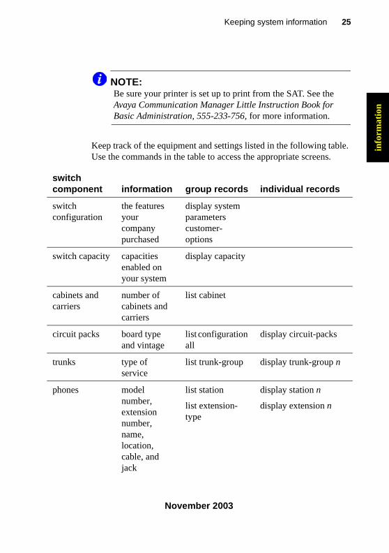
NOTE:Be sure your printer is set up to print from the SAT. See the Avaya Communication Manager Little Instruction Book for Basic Administration, 555-233-756, for more information.
Keep track of the equipment and settings listed in the following table. Use the commands in the table to access the appropriate screens.
switch component information group records individual records
switch configuration
the features your company purchased
display system parameters customer-options
switch capacity capacities enabled on your system
display capacity
cabinets and carriers
number of cabinets and carriers
list cabinet
circuit packs board type and vintage
list configuration all
display circuit-packs
trunks type of service
list trunk-group display trunk-group n
phones model number, extension number, name, location, cable, and jack
list station
list extension-type
display station n
display extension n
233758_6.book Page 25 Tuesday, August 5, 2003 6:22 AM
26 Retrieving baseline information
November 2003
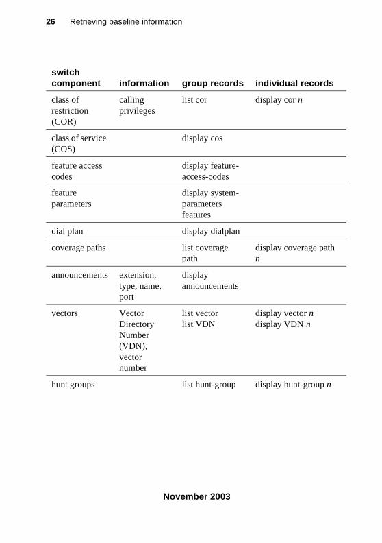
class of restriction (COR)
calling privileges
list cor display cor n
class of service (COS)
display cos
feature access codes
display feature-access-codes
feature parameters
display system-parameters features
dial plan display dialplan
coverage paths list coverage path
display coverage path n
announcements extension, type, name, port
display announcements
vectors Vector Directory Number (VDN), vector number
list vector list VDN
display vector ndisplay VDN n
hunt groups list hunt-group display hunt-group n
switch component information group records individual records
233758_6.book Page 26 Tuesday, August 5, 2003 6:22 AM
27Keeping system information
November 2003
info
rmat
ion
Securing backups
Backup your system regularly to keep your records up to date.
• Use save translations to backup changes to your switch.
• Use save announcements to backup changes to announcements.
To verify that a backup was successful, review the Command Completion Status field.
• If the status field says Success, then the backup of the translations or the announcements was successful.
• If the status field does not say Success, record the Error Code and use the following list to determine what happened:
— 1 = unable to save to active-spe device
— 2 = unable to save to standby-spe device
NOTE:See the Avaya Communication Manager Little Instruction Book for Basic Administration, 555-233-756, for more information on performing backups.
233758_6.book Page 27 Tuesday, August 5, 2003 6:22 AM

28 Securing backups
November 2003
233758_6.book Page 28 Tuesday, August 5, 2003 6:22 AM
29Checking system status
November 2003
stat
us
2 Checking system status
This section explains how to use switch information to keep track of the general health and status of your system. It tells you how to access system-wide and individual information, and describes how to check when changes are made to your system.
Problem solving strategies
As an administrator, one of your responsibilities is to check the status of your switch to determine whether it is performing properly. This is a proactive approach to system diagnostics.
• Use the status command to check on the operation of your system. See Viewing the system status on page 30 for more information.
• Use display alarms and display errors to closely monitor your switch. See Alarms and errors on page 49 for more information.
Another of your responsibilities is to respond to reports of phone problems from your users. You generally have to use a reactive approach to system diagnostics to perform this important function. See Solving common problems on page 37 for more information.
233758_6.book Page 29 Tuesday, August 5, 2003 6:22 AM
30 Problem solving strategies
November 2003
Viewing the system status
Use system status screens to monitor various parts of your system. To be prepared for problems, you’ll want to become familiar with what these reports look like when your system is operating well.
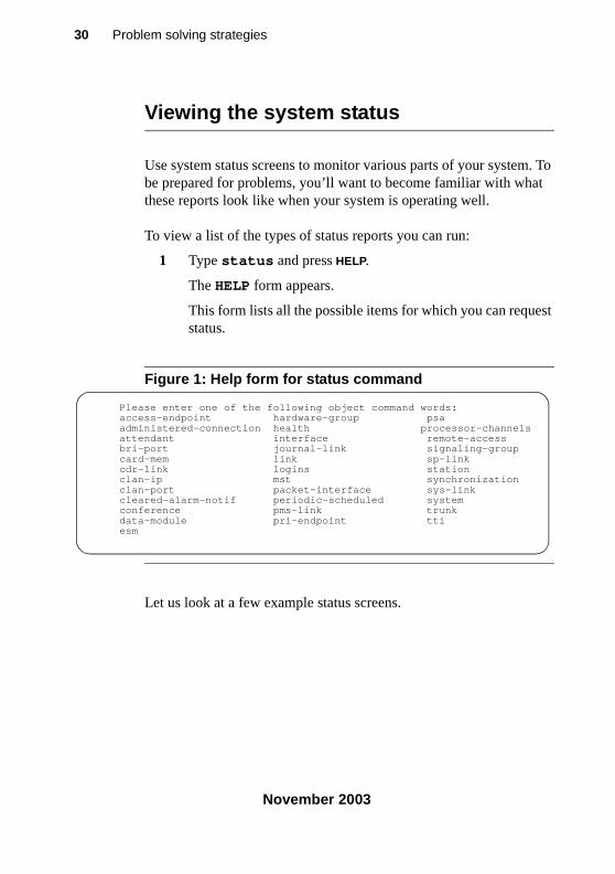
To view a list of the types of status reports you can run:
1 Type status and press HELP.
The HELP form appears.
This form lists all the possible items for which you can request status.
Figure 1: Help form for status command
Let us look at a few example status screens.
Please enter one of the following object command words:access-endpoint hardware-group psaadministered-connection health processor-channelsattendant interface remote-accessbri-port journal-link signaling-groupcard-mem link sp-linkcdr-link logins stationclan-ip mst synchronizationclan-port packet-interface sys-linkcleared-alarm-notif periodic-scheduled systemconference pms-link trunkdata-module pri-endpoint ttiesm
233758_6.book Page 30 Tuesday, August 5, 2003 6:22 AM
31Checking system status
November 2003
stat
us
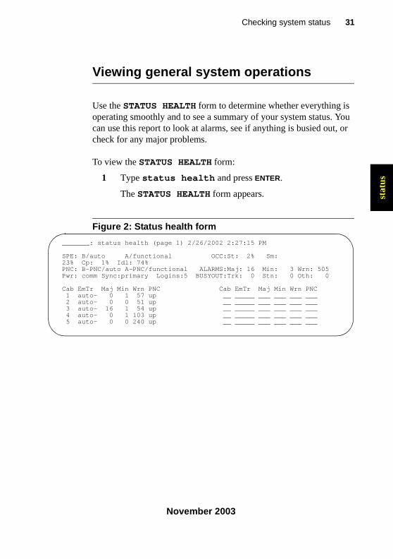
Viewing general system operations
Use the STATUS HEALTH form to determine whether everything is operating smoothly and to see a summary of your system status. You can use this report to look at alarms, see if anything is busied out, or check for any major problems.
To view the STATUS HEALTH form:
1 Type status health and press ENTER.
The STATUS HEALTH form appears.
Figure 2: Status health form
_______: status health (page 1) 2/26/2002 2:27:15 PM
SPE: B/auto A/functional OCC:St: 2% Sm: 23% Cp: 1% Idl: 74%PNC: B-PNC/auto A-PNC/functional ALARMS:Maj: 16 Min: 3 Wrn: 505Pwr: comm Sync:primary Logins:5 BUSYOUT:Trk: 0 Stn: 0 Oth: 0
Cab EmTr Maj Min Wrn PNC Cab EmTr Maj Min Wrn PNC1 auto- 0 1 57 up __ _____ ___ ___ ___ ___2 auto- 0 0 51 up __ _____ ___ ___ ___ ___3 auto- 16 1 54 up __ _____ ___ ___ ___ ___4 auto- 0 1 103 up __ _____ ___ ___ ___ ___5 auto- 0 0 240 up __ _____ ___ ___ ___ ___
233758_6.book Page 31 Tuesday, August 5, 2003 6:22 AM
32 Problem solving strategies
November 2003
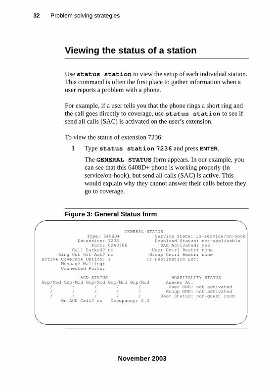
Viewing the status of a station
Use status station to view the setup of each individual station. This command is often the first place to gather information when a user reports a problem with a phone.
For example, if a user tells you that the phone rings a short ring and the call goes directly to coverage, use status station to see if send all calls (SAC) is activated on the user’s extension.
To view the status of extension 7236:
1 Type status station 7236 and press ENTER.
The GENERAL STATUS form appears. In our example, you can see that this 6408D+ phone is working properly (in-service/on-hook), but send all calls (SAC) is active. This would explain why they cannot answer their calls before they go to coverage.
Figure 3: General Status form
GENERAL STATUS Type: 6408D+ Service State: in-service/on-hook Extension: 7236 Download Status: not-applicable Port: 02A0306 SAC Activated? yes Call Parked? no User Cntrl Restr: none Ring Cut Off Act? no Group Cntrl Restr: noneActive Coverage Option: 1 CF Destination Ext: Message Waiting: Connected Ports:
ACD STATUS HOSPITALITY STATUSGrp/Mod Grp/Mod Grp/Mod Grp/Mod Grp/Mod Awaken At: / / / / / User DND: not activated / / / / / Group DND: not activated / / / / / Room Status: non-guest room On ACD Call? no Occupancy: 0.0
233758_6.book Page 32 Tuesday, August 5, 2003 6:22 AM

33Checking system status
November 2003
stat
us
Viewing the status of your cabinets
Use the SYSTEM STATUS CABINET form to become familiar with the service state of your individual cabinets. This form also reports any alarms against your cabinets.
To view the status of your system cabinets:
1 Type status system all-cabinets and press ENTER.
The SYSTEM STATUS CABINET form appears.
Figure 4: System Status Cabinet form
Using a number of the status commands can go a long way in helping you know if your system is running OK.
SYSTEM STATUS CABINET 1 SELECT SPE ALARMS TONE/ SERVICE SYSTEM SYSTEMSPE MODE SWITCH MAJOR MINOR CLOCK STATE CLOCK TONE1A standby auto 0 0 1A in standby standby1B active spe b 0 0 1B in active active SERVICE CONTROL DEDICATED SERVICE BUS ALARMS BUS OPEN BUSTDM STATE CHANNEL TONES PKT STATE MAJOR MINOR FAULTS LEADS1A in n n1B in y y 1 in n n 0 0
EMERGENCY SELECT SERVICE CABINETTRANSFER SWITCH EXP-LINK STATE MODE TYPE1A on 01A01-02A01 in active MCC1B auto-off 01B01-02B02 in standby
233758_6.book Page 33 Tuesday, August 5, 2003 6:22 AM
34 Problem solving strategies
November 2003
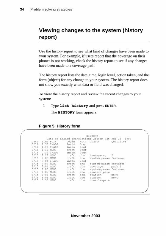
Viewing changes to the system (history report)
Use the history report to see what kind of changes have been made to your system. For example, if users report that the coverage on their phones is not working, check the history report to see if any changes have been made to a coverage path.
The history report lists the date, time, login level, action taken, and the form (object) for any change to your system. The history report does not show you exactly what data or field was changed.
To view the history report and review the recent changes to your system:
1 Type list history and press ENTER.
The HISTORY form appears.
Figure 5: History form
HISTORY Date of Loaded Translation: 2:48pm Sat Jul 26, 1997 Date Time Port Login Actn Object Qualifier 3/16 2:33 INADS inads logn 3/16 1:16 INADS inads logf 3/16 1:16 MGR1 craft logf 3/16 0:39 INADS inads logn 3/15 7:17 MGR1 craft cha hunt-group 2 3/15 7:05 MGR1 craft cha system-param features 3/15 7:04 INADS inads logf 3/15 7:04 MGR1 craft cha system-param features 3/15 7:04 MGR1 craft cha coverage path 1 3/15 7:03 MGR1 craft cha system-param features 3/15 6:09 MGR1 craft cha console-para 3/15 6:06 MGR1 craft add station next 3/15 6:06 MGR1 craft add station next 3/15 5:35 MGR1 craft cha console-para
233758_6.book Page 34 Tuesday, August 5, 2003 6:22 AM
35Checking system status
November 2003
stat
us
How can Avaya help?
With an Avaya Service Agreement or warranty coverage, your system running Communication Manager is linked to Avaya Expert Systems for constant remote monitoring, proactive diagnosis and trouble resolution. This electronic monitoring is so effective that 70% of all troubles are remotely identified, diagnosed, and resolved. This round-the-clock coverage is the best in the industry, helping to provide maximum up-time for your voice communication system.
Also, Avaya is the first in the industry to provide Power Surge Protection, completely covering the costs of product damage due to power surges. You are automatically covered if your system is under Warranty or Service Agreement, and power protection has been installed, all local and national electrical codes have been followed, and Avaya site requirements have been met. Service Agreement and warranty customers will receive first priority toward resolution of these problems.
233758_6.book Page 35 Tuesday, August 5, 2003 6:22 AM

36 How can Avaya help?
November 2003
233758_6.book Page 36 Tuesday, August 5, 2003 6:22 AM
37Solving common problems
November 2003
solv
ing
3 Solving common problems
This section tells you the questions to ask and the information to gather to solve some of the most basic phone problems. It also describes how to solve common call-center problems.
Diagnosing a problem
As a system administrator, an important part of your job is to respond to trouble calls from users. You can identify some of the most common of these problems by following a few simple steps, asking the right questions, and trying to recreate the problem.
Use a set of questions to determine if:
• the equipment or process has worked before and is now broken, or if this is a new set-up that you need to correct
• the problem comes from your company’s own equipment, or if the problem comes from your vendor
• the problem originates within your switch, or if the source of the problem is outside of your own facility
233758_6.book Page 37 Tuesday, August 5, 2003 6:22 AM
38 Solving common phone problems
November 2003
Ask the following basic questions of yourself, your users, and other switch administrators who work with you:
• Is this a new feature or piece of equipment, or did it work before but does not work now?
• Does the trouble arise when dialing outside the switch, dialing into the switch, or dialing inside the switch?
• Can we duplicate the problem?
Solving common phone problems
This section describes the approach that many administrators take to diagnose and correct common problems. Following is a list of suggested actions you can take if you have a problem.
• ask for the exact symptoms
• try to duplicate the problem or have the user show you the problem
• look at the phone
• find out if the phone was swapped out
• check the physical connections (for example, see if the phone is plugged in)
• check that the phone is where it is supposed to be
• try the phone at another location
• ask if the cord or handset was changed
• check status station
• use display station to look at the station screens page-by-page
• check the station screens for SAC, coverage paths
• look at printed switch records for discrepancies
• check the alarms and errors logs
233758_6.book Page 38 Tuesday, August 5, 2003 6:22 AM
39Solving common problems
November 2003
solv
ing
• clear any alarms and errors
• test the circuit packs
Let’s take a look at the types of problems users report to their system administrators, and see how to diagnose and correct the problem.
The user cannot dial out
A user calls to report that his phone “does not work.” Strangely enough, this seems to be the most commonly reported problem! Ask questions to find out what is really wrong and how to fix it.
To find out why a phone “does not work,” ask these questions:
• How does the phone “not work?” Does the problem occur when:
— they try to answer a ringing incoming call
— they try to make a call
• If the problem occurs when they try to make a call, is the call
— internal, station to station
— external, to an outside phone
• Is the problem with just one number, or are they unable to place any outgoing calls?
• Is this a new phone, or is this a new problem with an existing phone (were they able to call out before)
• Do they hear dial tone before they try to call?
• What do they hear after they dial?
— a tone of some kind
— a message
— static
— nothing
233758_6.book Page 39 Tuesday, August 5, 2003 6:22 AM
40 Solving common phone problems
November 2003
• If they hear a message after they dial, what is the exact message?
If the message says that the call cannot be completed as dialed, the problem is likely your ARS programming. See the Avaya Communication Manager Little Instruction Book for Basic Administration, 555-233-756, for more information on changing your outbound routing.
Incoming calls ring but do not reach the user
Another user calls to report that his phone “does not work.” Ask questions similar to the ones listed above. You determine that the user can call out, and that the phone rings but there is no call on the line when the user picks up.
Type status station to see if Send All Calls (SAC) is activated.
The message lamp on the phone does not go out
This problem often occurs even when the messages associated with the phone have been cleared.
To clear a message waiting light:
1 At the command prompt, type clear amw all n, where n is the extension, and press ENTER.
233758_6.book Page 40 Tuesday, August 5, 2003 6:22 AM
41Solving common problems
November 2003
solv
ing
Diagnosing general trunk problems
The following questions help you determine a problem with a trunk.
• Is the trouble on every call or is the trouble intermittent?
• Are you getting any sort of recordings when you try to dial out on this trunk?
• Can you identify the trunk in question?
Use a trunk access code (tac) to identify the trunk, especially if the console has a trunk ID button.
• Is there static on the call?
This is likely a problem with the trunk external to the switch.
• Have you notified your vendor of this problem?
Diagnosing tie trunk problems
The following questions help you determine a problem with a tie trunk.
• Is the problem on incoming calls only?
• Is the problem on outgoing calls only?
• What happens when you try to use this trunk?
• Have you notified the T1 vendor?
• Does this trunk connect to another location?
If so, try to determine the IL number of that location.
• Do you know the circuit ID of this trunk?
233758_6.book Page 41 Tuesday, August 5, 2003 6:22 AM
42 Solving common phone problems
November 2003
Diagnosing modem problems
The following questions help you determine a problem with a modem.
• What is the extension of the modem?
• Is the modem connected through the switch?
• What is the modem connected to?
For example, computer, fax, or CMS?
• Have the setup options been changed or checked recently?
• What company manufactures the modem?
• What is the model number?
Diagnosing printer troubles
The following questions help you determine a problem with a printer.
• What is the problem with the printer?
• What is the printer used for?
For example, is it connected to the switch, CMS, CAS, or maybe AUDIX?
• Who manufactures the printer?
• What is the model number?
233758_6.book Page 42 Tuesday, August 5, 2003 6:22 AM
43Solving common problems
November 2003
solv
ing
Diagnosing password, login, andterminal access problems
If the problem is with remote dial-in access, ask:
• How do you dial in?
• What type of software or dialing program do you use?
• What error messages do you see when you try to dial in?
If your password expired, is not working, or is incorrect, call Avaya for assistance in getting the issue resolved.
Diagnosing SAT problems
If the problem is with the System Access Terminal (SAT), ask:
• What type of terminal is it?
• What type of trouble are you having?
Solving call center problems
This section helps you identify and solve common problems affecting hunt groups, splits, announcements, and caller access.
The tables below describe symptoms and solutions for common problems in call centers not using ACD or call vectoring.
233758_6.book Page 43 Tuesday, August 5, 2003 6:22 AM
44 Solving call center problems
November 2003
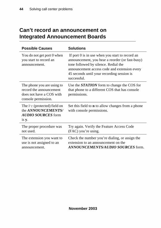
Can’t record an announcement onIntegrated Announcement Boards
Possible Causes Solutions
You do not get port 0 when you start to record an announcement.
If port 0 is in use when you start to record an announcement, you hear a reorder (or fast-busy) tone followed by silence. Redial the announcement access code and extension every 45 seconds until your recording session is successful.
The phone you are using to record the announcement does not have a COS with console permission.
Use the STATION form to change the COS for that phone to a different COS that has console permissions.
The Pr (protected) field on the ANNOUNCEMENTS/AUDIO SOURCES form is y.
Set this field to n to allow changes from a phone with console permissions.
The proper procedure was not used.
Try again. Verify the Feature Access Code (FAC) you’re using.
The extension you want to use is not assigned to an announcement.
Check the number you’re dialing, or assign the extension to an announcement on the ANNOUNCEMENTS/AUDIO SOURCES form.
233758_6.book Page 44 Tuesday, August 5, 2003 6:22 AM
45Solving common problems
November 2003
solv
ing
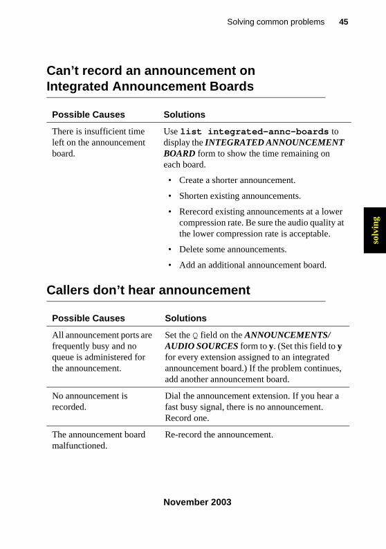
There is insufficient time left on the announcement board.
Use list integrated-annc-boards to display the INTEGRATED ANNOUNCEMENT BOARD form to show the time remaining on each board.
• Create a shorter announcement.
• Shorten existing announcements.
• Rerecord existing announcements at a lower compression rate. Be sure the audio quality at the lower compression rate is acceptable.
• Delete some announcements.
• Add an additional announcement board.
Can’t record an announcement onIntegrated Announcement Boards
Possible Causes Solutions
Callers don’t hear announcement
Possible Causes Solutions
All announcement ports are frequently busy and no queue is administered for the announcement.
Set the Q field on the ANNOUNCEMENTS/AUDIO SOURCES form to y. (Set this field to y for every extension assigned to an integrated announcement board.) If the problem continues, add another announcement board.
No announcement is recorded.
Dial the announcement extension. If you hear a fast busy signal, there is no announcement. Record one.
The announcement board malfunctioned.
Re-record the announcement.
233758_6.book Page 45 Tuesday, August 5, 2003 6:22 AM
46 Solving call center problems
November 2003
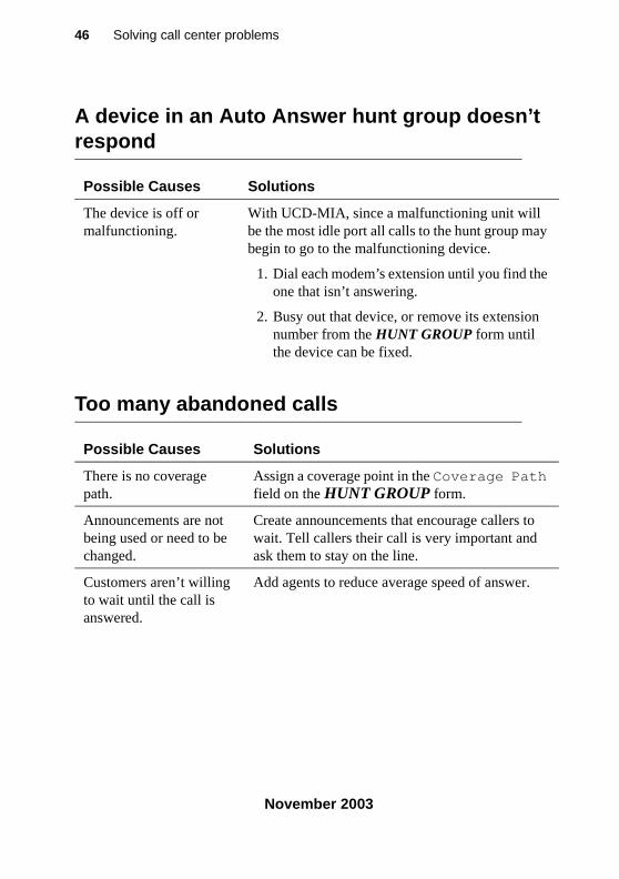
A device in an Auto Answer hunt group doesn’t respond
Possible Causes Solutions
The device is off or malfunctioning.
With UCD-MIA, since a malfunctioning unit will be the most idle port all calls to the hunt group may begin to go to the malfunctioning device.
1. Dial each modem’s extension until you find the one that isn’t answering.
2. Busy out that device, or remove its extension number from the HUNT GROUP form until the device can be fixed.
Too many abandoned calls
Possible Causes Solutions
There is no coverage path.
Assign a coverage point in the Coverage Path field on the HUNT GROUP form.
Announcements are not being used or need to be changed.
Create announcements that encourage callers to wait. Tell callers their call is very important and ask them to stay on the line.
Customers aren’t willing to wait until the call is answered.
Add agents to reduce average speed of answer.
233758_6.book Page 46 Tuesday, August 5, 2003 6:22 AM
47Solving common problems
November 2003
solv
ing
l
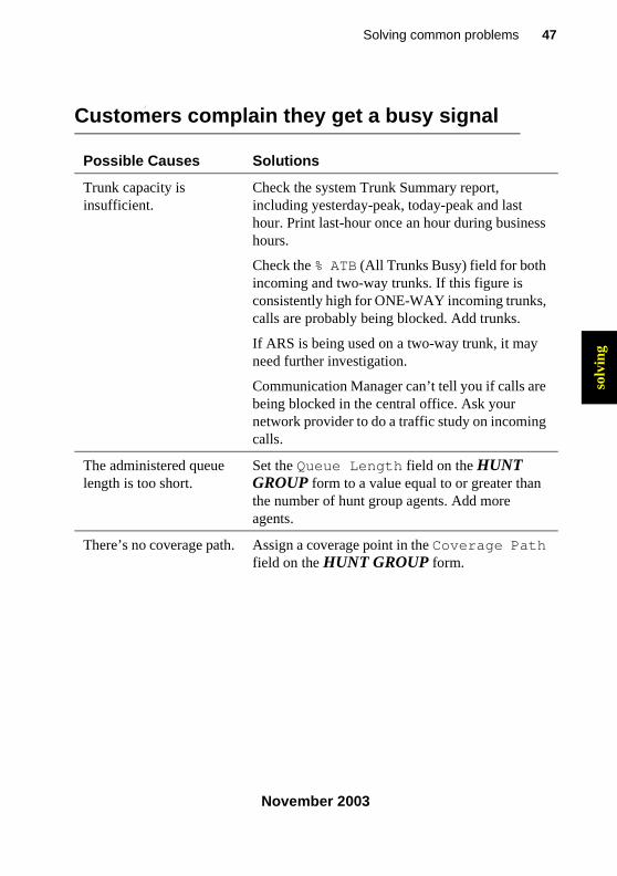
Customers complain they get a busy signal
Possible Causes Solutions
Trunk capacity is insufficient.
Check the system Trunk Summary report, including yesterday-peak, today-peak and last hour. Print last-hour once an hour during business hours.
Check the % ATB (All Trunks Busy) field for both incoming and two-way trunks. If this figure is consistently high for ONE-WAY incoming trunks, calls are probably being blocked. Add trunks.
If ARS is being used on a two-way trunk, it may need further investigation.
Communication Manager can’t tell you if calls are being blocked in the central office. Ask your network provider to do a traffic study on incoming calls.
The administered queue length is too short.
Set the Queue Length field on the HUNT GROUP form to a value equal to or greater than the number of hunt group agents. Add more agents.
There’s no coverage path. Assign a coverage point in the Coverage Path field on the HUNT GROUP form.
233758_6.book Page 47 Tuesday, August 5, 2003 6:22 AM

48 Solving call center problems
November 2003
233758_6.book Page 48 Tuesday, August 5, 2003 6:22 AM
49Alarms and errors
November 2003
alar
ms/
erro
rs
4 Alarms and errors
This section is for adventurous administrators who are curious about how to diagnose and fix common problems. The information here will help you understand how to read and interpret:
• error logs
• alarm logs
Maintenance reports
Avaya Communication Manager monitors many switch components. When a component fails or performs unacceptably, the subsystem generates two kinds of reports:
• detailed reports in the error log
• general reports in the alarm log
The system detects error conditions in its components through Maintenance Objects (MO). MOs are the software modules that monitor, test, and report possible fault conditions.
233758_6.book Page 49 Tuesday, August 5, 2003 6:22 AM
50 Maintenance reports
November 2003
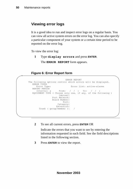
Viewing error logs
It is a good idea to run and inspect error logs on a regular basis. You can view all active system errors on the error log. You can also specify a particular component of your system or a certain time period to be reported on the error log.
To view the error log:
1 Type display errors and press ENTER.
The ERROR REPORT form appears.
Figure 6: Error Report form
2 To see all current errors, press ENTER OR
Indicate the errors that you want to see by entering the information requested in each field. See the field descriptions listed in the following section.
3 Press ENTER to view the report.
ERROR REPORT The following options control which errors will be displayed. ERROR TYPES Error Type: Error List: active-alarms REPORT PERIOD Interval: a From: / / : To: / / : EQUIPMENT TYPE ( Choose only one, if any, of the following ) Cabinet: Port Network: Board Number: Port: Category: Extension: Trunk ( group/member ): /
233758_6.book Page 50 Tuesday, August 5, 2003 6:22 AM
51Alarms and errors
November 2003
alar
ms/
erro
rs
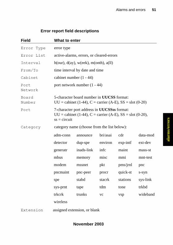
Error report field descriptions
Field What to enter
Error Type error type
Error List active-alarms, errors, or cleared-errors
Interval h(our), d(ay), w(eek), m(onth), a(ll)
From/To time interval by date and time
Cabinet cabinet number (1 - 44)
Port Network
port network number (1 - 44)
Board Number
5-character board number in UUCSS format:UU = cabinet (1-44), C = carrier (A-E), SS = slot (0-20)
Port 7-character port address in UUCSSss format:UU = cabinet (1-44), C = carrier (A-E), SS = slot (0-20), ss = circuit
Category category name (choose from the list below):
adm-conn announce bri/asai cdr data-mod
detector dup-spe environ exp-intf ext-dev
generatr inads-link infc maint mass-st
mbus memory misc mmi mnt-test
modem mssnet pkt pms/jrnl pnc
pncmaint pnc-peer procr quick-st s-syn
spe stabd stacrk stations sys-link
sys-prnt tape tdm tone trkbd
trkcrk trunks vc vsp wideband
wireless
Extension assigned extension, or blank
233758_6.book Page 51 Tuesday, August 5, 2003 6:22 AM
52 Maintenance reports
November 2003
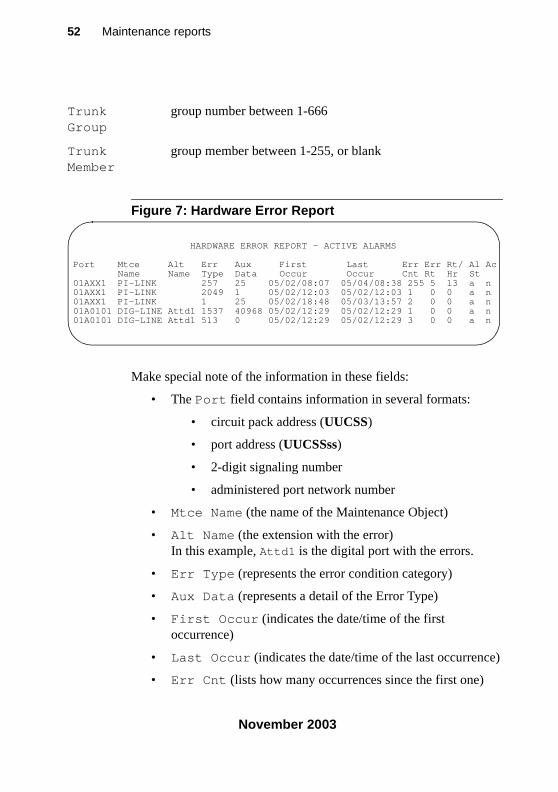
Figure 7: Hardware Error Report
Make special note of the information in these fields:
• The Port field contains information in several formats:
• circuit pack address (UUCSS)
• port address (UUCSSss)
• 2-digit signaling number
• administered port network number
• Mtce Name (the name of the Maintenance Object)
• Alt Name (the extension with the error)In this example, Attd1 is the digital port with the errors.
• Err Type (represents the error condition category)
• Aux Data (represents a detail of the Error Type)
• First Occur (indicates the date/time of the first occurrence)
• Last Occur (indicates the date/time of the last occurrence)
• Err Cnt (lists how many occurrences since the first one)
Trunk Group
group number between 1-666
Trunk Member
group member between 1-255, or blank
HARDWARE ERROR REPORT - ACTIVE ALARMS
Port Mtce Alt Err Aux First Last Err Err Rt/ Al AcName Name Type Data Occur Occur Cnt Rt Hr St
01AXX1 PI-LINK 257 25 05/02/08:07 05/04/08:38 255 5 13 a n01AXX1 PI-LINK 2049 1 05/02/12:03 05/02/12:03 1 0 0 a n01AXX1 PI-LINK 1 25 05/02/18:48 05/03/13:57 2 0 0 a n01A0101 DIG-LINE Attd1 1537 40968 05/02/12:29 05/02/12:29 1 0 0 a n01A0101 DIG-LINE Attd1 513 0 05/02/12:29 05/02/12:29 3 0 0 a n
233758_6.book Page 52 Tuesday, August 5, 2003 6:22 AM
53Alarms and errors
November 2003
alar
ms/
erro
rs
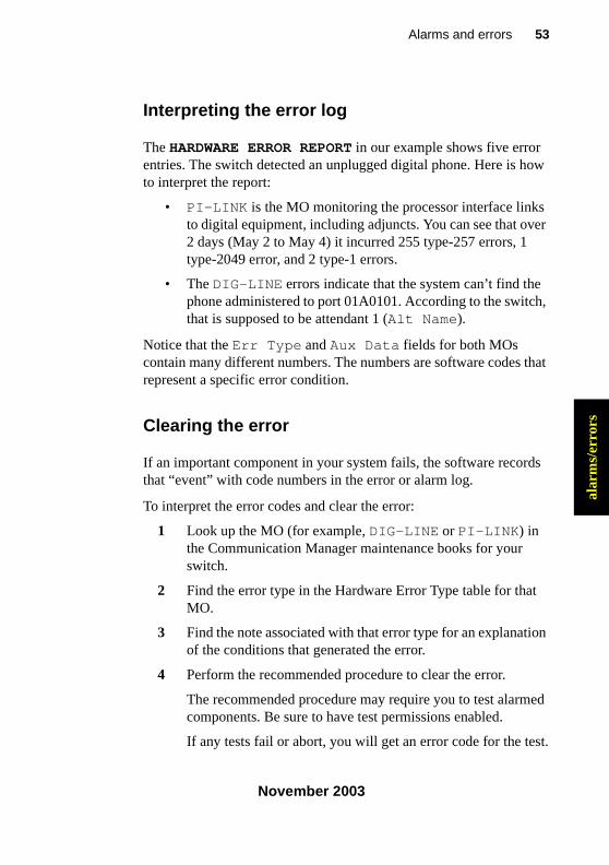
Interpreting the error log
The HARDWARE ERROR REPORT in our example shows five error entries. The switch detected an unplugged digital phone. Here is how to interpret the report:
• PI-LINK is the MO monitoring the processor interface links to digital equipment, including adjuncts. You can see that over 2 days (May 2 to May 4) it incurred 255 type-257 errors, 1 type-2049 error, and 2 type-1 errors.
• The DIG-LINE errors indicate that the system can’t find the phone administered to port 01A0101. According to the switch, that is supposed to be attendant 1 (Alt Name).
Notice that the Err Type and Aux Data fields for both MOs contain many different numbers. The numbers are software codes that represent a specific error condition.
Clearing the error
If an important component in your system fails, the software records that “event” with code numbers in the error or alarm log.
To interpret the error codes and clear the error:
1 Look up the MO (for example, DIG-LINE or PI-LINK) in the Communication Manager maintenance books for your switch.
2 Find the error type in the Hardware Error Type table for that MO.
3 Find the note associated with that error type for an explanation of the conditions that generated the error.
4 Perform the recommended procedure to clear the error.
The recommended procedure may require you to test alarmed components. Be sure to have test permissions enabled.
If any tests fail or abort, you will get an error code for the test.
233758_6.book Page 53 Tuesday, August 5, 2003 6:22 AM
54 Maintenance reports
November 2003
5 Look up the test error code by MO in your Communication Manager maintenance books.
6 Find the numbered test listed in the test results.
7 Look for the correct combination of error code and test result in the numbered-test tables.
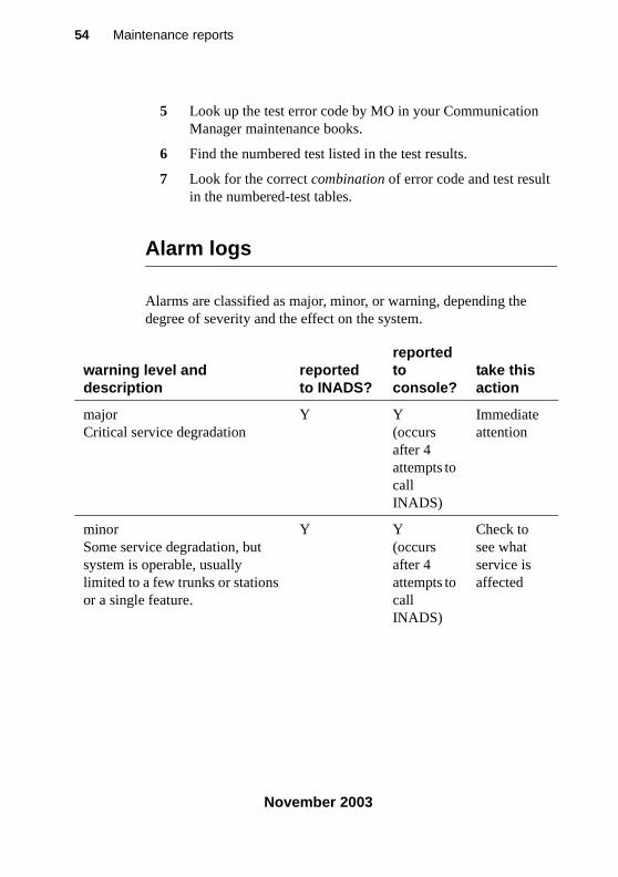
Alarm logs
Alarms are classified as major, minor, or warning, depending the degree of severity and the effect on the system.
warning level and description
reported to INADS?
reported to console?
take this action
majorCritical service degradation
Y Y(occurs after 4 attempts to call INADS)
Immediate attention
minorSome service degradation, but system is operable, usually limited to a few trunks or stations or a single feature.
Y Y(occurs after 4 attempts to call INADS)
Check to see what service is affected
233758_6.book Page 54 Tuesday, August 5, 2003 6:22 AM
55Alarms and errors
November 2003
alar
ms/
erro
rs
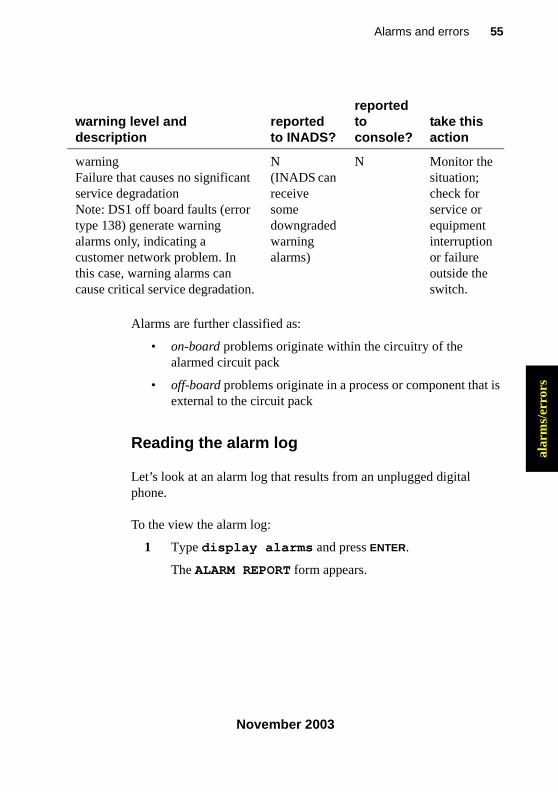
Alarms are further classified as:
• on-board problems originate within the circuitry of the alarmed circuit pack
• off-board problems originate in a process or component that is external to the circuit pack
Reading the alarm log
Let’s look at an alarm log that results from an unplugged digital phone.
To the view the alarm log:
1 Type display alarms and press ENTER.
The ALARM REPORT form appears.
warningFailure that causes no significant service degradationNote: DS1 off board faults (error type 138) generate warning alarms only, indicating a customer network problem. In this case, warning alarms can cause critical service degradation.
N(INADS can receive some downgraded warning alarms)
N Monitor the situation; check for service or equipment interruption or failure outside the switch.
warning level and description
reported to INADS?
reported to console?
take this action
233758_6.book Page 55 Tuesday, August 5, 2003 6:22 AM
56 Maintenance reports
November 2003
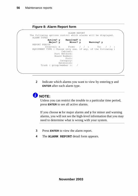
Figure 8: Alarm Report form
2 Indicate which alarms you want to view by entering y and ENTER after each alarm type.
NOTE:Unless you can restrict the trouble to a particular time period, press ENTER to see all active alarms.
If you choose n for major alarms and y for minor and warning alarms, you will not see the high-level information that you may need to determine what is wrong with your system.
3 Press ENTER to view the alarm report.
4 The ALARM REPORT detail form appears.
ALARM REPORT The following options control which alarms will be displayed. ALARM TYPES Active? y Resolved? n Major? y Minor? y Warning? y REPORT PERIOD Interval: m From: / / : To: / / : EQUIPMENT TYPE ( Choose only one, if any, of the following ) Cabinet: Port Network: Board Number: Port: Category: Extension: Trunk ( group/member ): /
233758_6.book Page 56 Tuesday, August 5, 2003 6:22 AM
57Alarms and errors
November 2003
alar
ms/
erro
rs
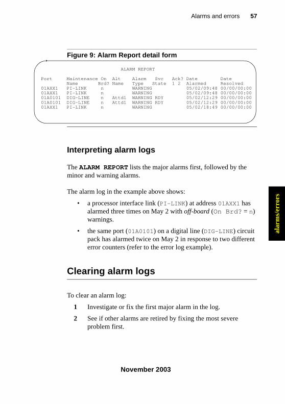
Figure 9: Alarm Report detail form
Interpreting alarm logs
The ALARM REPORT lists the major alarms first, followed by the minor and warning alarms.
The alarm log in the example above shows:
• a processor interface link (PI-LINK) at address 01AXX1 has alarmed three times on May 2 with off-board (On Brd? = n) warnings.
• the same port (01A0101) on a digital line (DIG-LINE) circuit pack has alarmed twice on May 2 in response to two different error counters (refer to the error log example).
Clearing alarm logs
To clear an alarm log:
1 Investigate or fix the first major alarm in the log.
2 See if other alarms are retired by fixing the most severe problem first.
ALARM REPORT
Port Maintenance On Alt Alarm Svc Ack? Date DateName Brd? Name Type State 1 2 Alarmed Resolved
01AXX1 PI-LINK n WARNING 05/02/09:48 00/00/00:0001AXX1 PI-LINK n WARNING 05/02/09:48 00/00/00:0001A0101 DIG-LINE n Attd1 WARNING RDY 05/02/12:29 00/00/00:0001A0101 DIG-LINE n Attd1 WARNING RDY 05/02/12:29 00/00/00:0001AXX1 PI-LINK n WARNING 05/02/18:49 00/00/00:00
233758_6.book Page 57 Tuesday, August 5, 2003 6:22 AM
58 Understanding common error types
November 2003
Assigning alarm buttons
You can administer feature button lamps on any phone to act as alarm indicators, similar to the alarm lamp on the attendant console. The following table describes the meaning of the green light associated with an alarm button.
Press the alarm button to turn off the light. The light flashes again if the alarm is still active when the next maintenance routine runs.
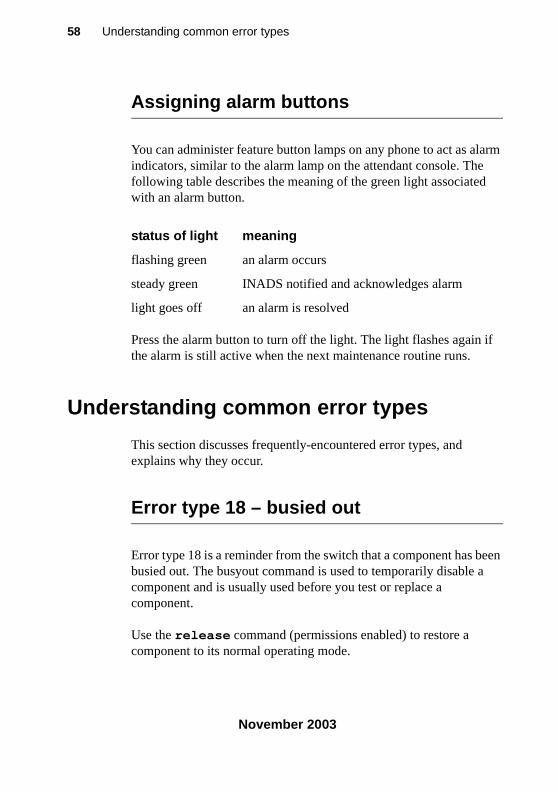
Understanding common error types
This section discusses frequently-encountered error types, and explains why they occur.
Error type 18 – busied out
Error type 18 is a reminder from the switch that a component has been busied out. The busyout command is used to temporarily disable a component and is usually used before you test or replace a component.
Use the release command (permissions enabled) to restore a component to its normal operating mode.
status of light meaning
flashing green an alarm occurs
steady green INADS notified and acknowledges alarm
light goes off an alarm is resolved
233758_6.book Page 58 Tuesday, August 5, 2003 6:22 AM
59Alarms and errors
November 2003
alar
ms/
erro
rs
For example, you receive a complaint that a phone does not work. As part of your diagnosis, you:
• use status station
OR
• view the hardware error report for error 18
To view a hardware error report for error 18:
1 Type display errors and press ENTER.
The HARDWARE ERROR REPORT form appears.
2 Fill in the Err Type field and press ENTER.
In our example, type 18.
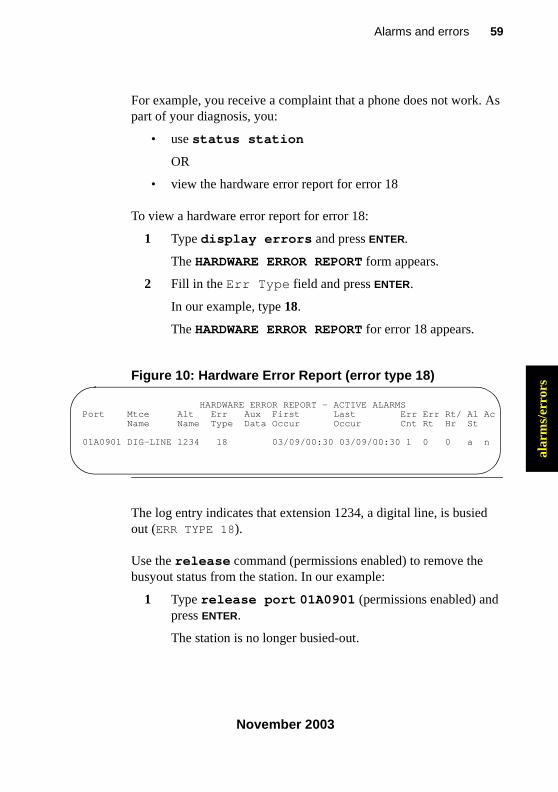
The HARDWARE ERROR REPORT for error 18 appears.
Figure 10: Hardware Error Report (error type 18)
The log entry indicates that extension 1234, a digital line, is busied out (ERR TYPE 18).
Use the release command (permissions enabled) to remove the busyout status from the station. In our example:
1 Type release port 01A0901 (permissions enabled) and press ENTER.
The station is no longer busied-out.
HARDWARE ERROR REPORT - ACTIVE ALARMS Port Mtce Alt Err Aux First Last Err Err Rt/ Al Ac
Name Name Type Data Occur Occur Cnt Rt Hr St
01A0901 DIG-LINE 1234 18 03/09/00:30 03/09/00:30 1 0 0 a n
233758_6.book Page 59 Tuesday, August 5, 2003 6:22 AM
60 Understanding common error types
November 2003
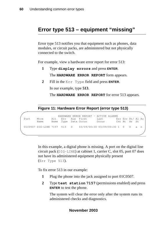
Error type 513 – equipment “missing”
Error type 513 notifies you that equipment such as phones, data modules, or circuit packs, are administered but not physically connected to the switch.
For example, view a hardware error report for error 513:
1 Type display errors and press ENTER.
The HARDWARE ERROR REPORT form appears.
2 Fill in the Err Type field and press ENTER.
In our example, type 513.
The HARDWARE ERROR REPORT for error 513 appears.
Figure 11: Hardware Error Report (error type 513)
In this example, a digital phone is missing. A port on the digital line circuit pack (DIG-LINE) at cabinet 1, carrier C, slot 05, port 07 does not have its administered equipment physically present (Err Type 513).
To fix error 513 in our example:
1 Plug the phone into the jack assigned to port 01C0507.
2 Type test station 7157 (permissions enabled) and press ENTER to test the phone.
The system will clear the error only after the system runs its administered checks and diagnostics.
HARDWARE ERROR REPORT - ACTIVE ALARMS Port Mtce Alt Err Aux First Last Err Err Rt/ Al Ac
Name Name Type Data Occur Occur Cnt Rt Hr St
01C0507 DIG-LINE 7157 513 0 03/09/00:30 03/09/00:30 1 0 0 a n
233758_6.book Page 60 Tuesday, August 5, 2003 6:22 AM
61Alarms and errors
November 2003
alar
ms/
erro
rs
Error type 1 — circuit pack removed
Error type 1 often indicates that an administered circuit pack has been removed.
To correct the problem and clear Error type 1:
1 Replace and latch the circuit pack in its administered slot.
The next time the system runs its routine maintenance program, it should be able to “see” the circuit pack and the error will not appear.
Preventing alarms and errors
This section lists a few common causes of unnecessary alarms.
Turn off maintenance
The Remote Loop-Around Test sends a burst of current to activate a phone’s ringer. If the ringer responds, the test detects the return. Data modules, fax machines and modems do not have ringers and do not respond to this test. This generates an error on that port.
You should turn off this test for data modules, fax machines and modems. Turning off the test does not affect the performance of any of these devices.
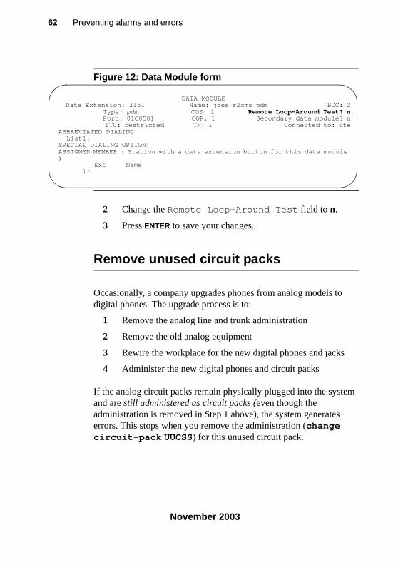
To turn off the maintenance test:
1 Type change data-module n, where n is the extension number, and press ENTER.
The DATA MODULE form appears.
233758_6.book Page 61 Tuesday, August 5, 2003 6:22 AM
62 Preventing alarms and errors
November 2003
Figure 12: Data Module form
2 Change the Remote Loop-Around Test field to n.
3 Press ENTER to save your changes.
Remove unused circuit packs
Occasionally, a company upgrades phones from analog models to digital phones. The upgrade process is to:
1 Remove the analog line and trunk administration
2 Remove the old analog equipment
3 Rewire the workplace for the new digital phones and jacks
4 Administer the new digital phones and circuit packs
If the analog circuit packs remain physically plugged into the system and are still administered as circuit packs (even though the administration is removed in Step 1 above), the system generates errors. This stops when you remove the administration (change circuit-pack UUCSS) for this unused circuit pack.
DATA MODULE Data Extension: 3151 Name: joes r2cms pdm BCC: 2 Type: pdm COS: 1 Remote Loop-Around Test? n Port: 01C0501 COR: 1 Secondary data module? n ITC: restricted TN: 1 Connected to: dteABBREVIATED DIALING List1: SPECIAL DIALING OPTION: ASSIGNED MEMBER ( Station with a data extension button for this data module ) Ext Name 1:
233758_6.book Page 62 Tuesday, August 5, 2003 6:22 AM
63Alarms and errors
November 2003
alar
ms/
erro
rs
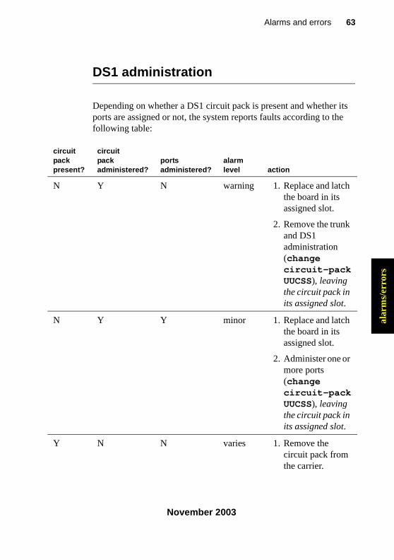
DS1 administration
Depending on whether a DS1 circuit pack is present and whether its ports are assigned or not, the system reports faults according to the following table:
circuitpackpresent?
circuitpackadministered?
portsadministered?
alarmlevel action
N Y N warning 1. Replace and latch the board in its assigned slot.
2. Remove the trunk and DS1 administration (change circuit-pack UUCSS), leaving the circuit pack in its assigned slot.
N Y Y minor 1. Replace and latch the board in its assigned slot.
2. Administer one or more ports (change circuit-pack UUCSS), leaving the circuit pack in its assigned slot.
Y N N varies 1. Remove the circuit pack from the carrier.
233758_6.book Page 63 Tuesday, August 5, 2003 6:22 AM

64 Preventing alarms and errors
November 2003
233758_6.book Page 64 Tuesday, August 5, 2003 6:22 AM
65Using features to troubleshoot
November 2003
feat
ures
5 Using features to troubleshoot
Troubleshooting
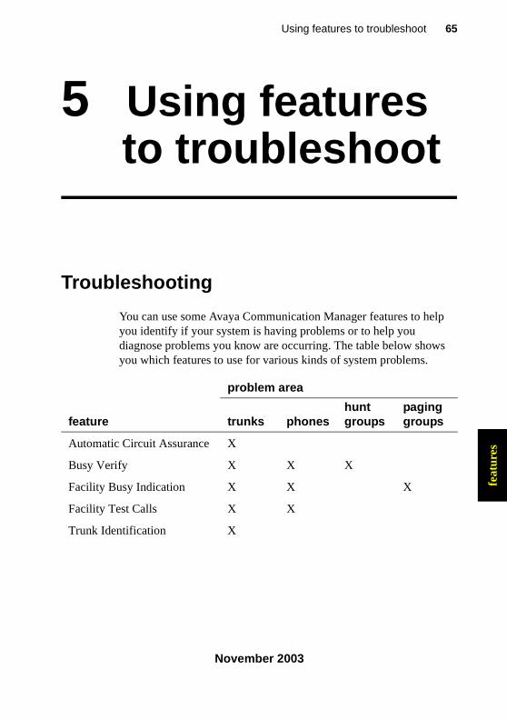
You can use some Avaya Communication Manager features to help you identify if your system is having problems or to help you diagnose problems you know are occurring. The table below shows you which features to use for various kinds of system problems.
feature
problem area
trunks phoneshuntgroups
paginggroups
Automatic Circuit Assurance X
Busy Verify X X X
Facility Busy Indication X X X
Facility Test Calls X X
Trunk Identification X
233758_6.book Page 65 Tuesday, August 5, 2003 6:22 AM
66 Troubleshooting
November 2003
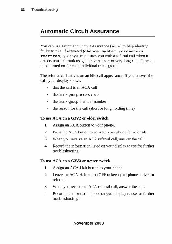
Automatic Circuit Assurance
You can use Automatic Circuit Assurance (ACA) to help identify faulty trunks. If activated (change system-parameters features), your system notifies you with a referral call when it detects unusual trunk usage like very short or very long calls. It needs to be turned on for each individual trunk group.
The referral call arrives on an idle call appearance. If you answer the call, your display shows:
• that the call is an ACA call
• the trunk-group access code
• the trunk-group member number
• the reason for the call (short or long holding time)
To use ACA on a G3V2 or older switch
1 Assign an ACA button to your phone.
2 Press the ACA button to activate your phone for referrals.
3 When you receive an ACA referral call, answer the call.
4 Record the information listed on your display to use for further troubleshooting.
To use ACA on a G3V3 or newer switch
1 Assign an ACA-Halt button to your phone.
2 Leave the ACA-Halt button OFF to keep your phone active for referrals.
3 When you receive an ACA referral call, answer the call.
4 Record the information listed on your display to use for further troubleshooting.
233758_6.book Page 66 Tuesday, August 5, 2003 6:22 AM
67Using features to troubleshoot
November 2003
feat
ures
Busy Verify
You can use Busy Verify to place test calls to check the busy condition of trunks, phones, or hunt groups. This test helps you determine if the trunk, phone, or hunt group is busy because of heavy use or appears busy because of a problem.
To use Busy Verify, you should administer a Busy Verify button on your phone.
To busy-verify a phone
1 Press the Busy Verify button on your phone.
The busy verify light turns green.
2 Dial the extension of the phone you want to test.
You hear a tone and see a display. The following table describes what the tone and display indicate and how to respond.
display tone frequencypattern(seconds)
status of extension next step
Invalid intercept 440 Hzalternating620 Hz
.25 on
.25 onrepeated
invalid number cancel and try again
Terminated
ringback combined440 Hz +480 Hz
1 on3 offrepeated
idle and ringing (working properly)
release the call
Bridged none bridged onto active call (working properly)
release the call
233758_6.book Page 67 Tuesday, August 5, 2003 6:22 AM
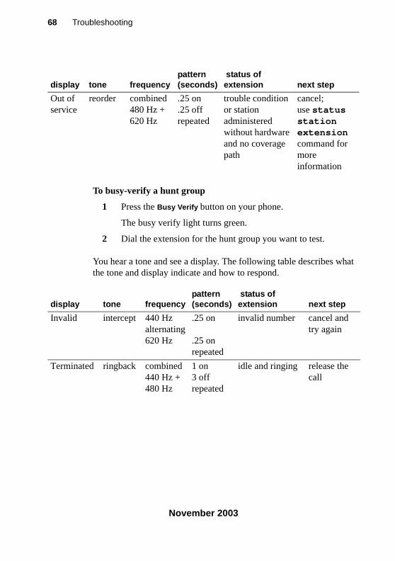
68 Troubleshooting
November 2003
To busy-verify a hunt group
1 Press the Busy Verify button on your phone.
The busy verify light turns green.
2 Dial the extension for the hunt group you want to test.
You hear a tone and see a display. The following table describes what the tone and display indicate and how to respond.
Out of service
reorder combined480 Hz +620 Hz
.25 on
.25 offrepeated
trouble condition or station administered without hardware and no coverage path
cancel;use status station extensioncommand for more information
display tone frequencypattern(seconds)
status of extension next step
display tone frequencypattern(seconds)
status of extension next step
Invalid intercept 440 Hzalternating620 Hz
.25 on
.25 onrepeated
invalid number cancel and try again
Terminated ringback combined440 Hz +480 Hz
1 on3 offrepeated
idle and ringing release the call
233758_6.book Page 68 Tuesday, August 5, 2003 6:22 AM
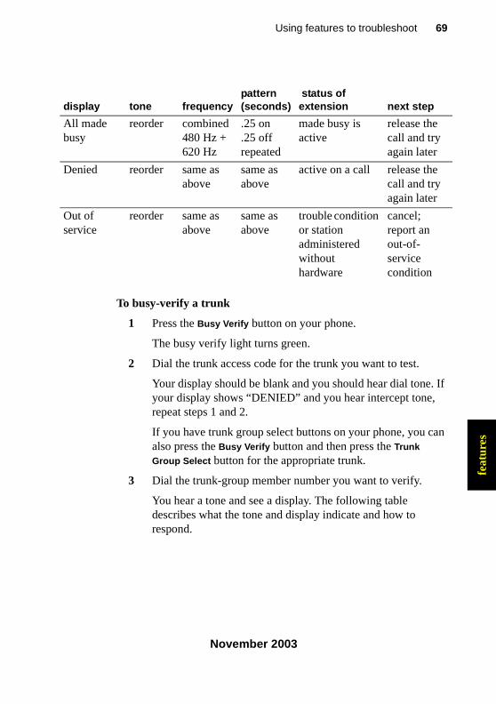
69Using features to troubleshoot
November 2003
feat
ures
To busy-verify a trunk
1 Press the Busy Verify button on your phone.
The busy verify light turns green.
2 Dial the trunk access code for the trunk you want to test.
Your display should be blank and you should hear dial tone. If your display shows “DENIED” and you hear intercept tone, repeat steps 1 and 2.
If you have trunk group select buttons on your phone, you can also press the Busy Verify button and then press the Trunk
Group Select button for the appropriate trunk.
3 Dial the trunk-group member number you want to verify.
You hear a tone and see a display. The following table describes what the tone and display indicate and how to respond.
All made busy
reorder combined480 Hz +620 Hz
.25 on
.25 offrepeated
made busy is active
release the call and try again later
Denied reorder same as above
same as above
active on a call release the call and try again later
Out of service
reorder same as above
same as above
trouble condition or station administered without hardware
cancel; report an out-of-service condition
display tone frequencypattern(seconds)
status of extension next step
233758_6.book Page 69 Tuesday, August 5, 2003 6:22 AM
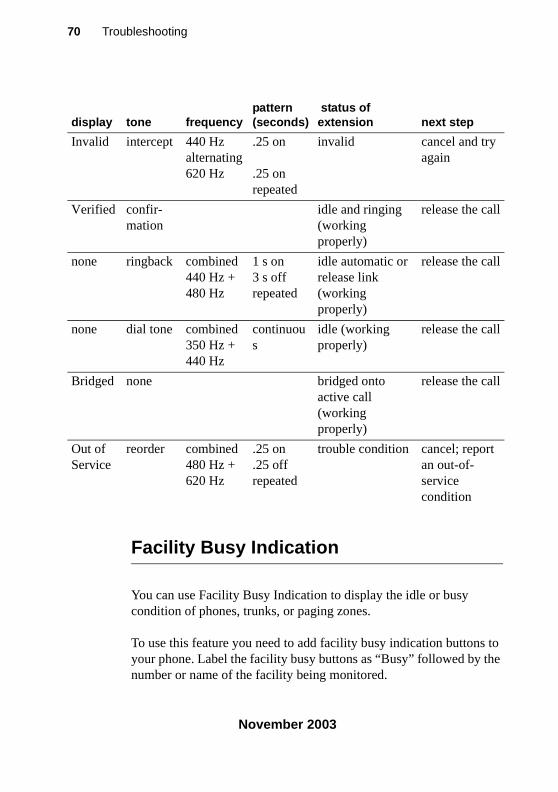
70 Troubleshooting
November 2003
Facility Busy Indication
You can use Facility Busy Indication to display the idle or busy condition of phones, trunks, or paging zones.
To use this feature you need to add facility busy indication buttons to your phone. Label the facility busy buttons as “Busy” followed by the number or name of the facility being monitored.
display tone frequencypattern(seconds)
status of extension next step
Invalid intercept 440 Hzalternating620 Hz
.25 on
.25 on repeated
invalid cancel and try again
Verified confir-mation
idle and ringing (working properly)
release the call
none ringback combined440 Hz +480 Hz
1 s on3 s offrepeated
idle automatic or release link(working properly)
release the call
none dial tone combined350 Hz +440 Hz
continuous
idle (working properly)
release the call
Bridged none bridged onto active call (working properly)
release the call
Out ofService
reorder combined480 Hz +620 Hz
.25 on
.25 offrepeated
trouble condition cancel; report an out-of-service condition
233758_6.book Page 70 Tuesday, August 5, 2003 6:22 AM
71Using features to troubleshoot
November 2003
feat
ures
If the green light associated with the Facility Busy Indication button stays lit for a long time, the facility may have a problem.
Facility Test Calls
You can use Facility Test Calls to place test calls to specific trunks or phones. Because this feature bypasses the regular system traffic, it is very helpful in finding noisy lines and other problems. However, this feature can be easily misused by outside parties. Disable this feature when you are not using it.
SECURITY ALERT: !Whenever you use this feature, enable the feature access code only for the tests you want to make. Be sure to immediately remove the access code when you are through testing because leaving this feature enabled can leave you open to security breaches.
To place a test call to a trunk or touch-tone phone
1 At the system terminal, enable a feature access code for Facility Test Call.
2 At your phone, dial the feature access code for Facility Test Call. Listen for dial tone.
3 Dial the 6- or 7-digit port address in UUCSSss format, where:
UU = cabinet number (01, 02, etc.)C = carrier number (A=1, B=2, C=3, D=4, E=5)SS = slot number (depends on system)ss = port number (depends on circuit pack)
233758_6.book Page 71 Tuesday, August 5, 2003 6:22 AM
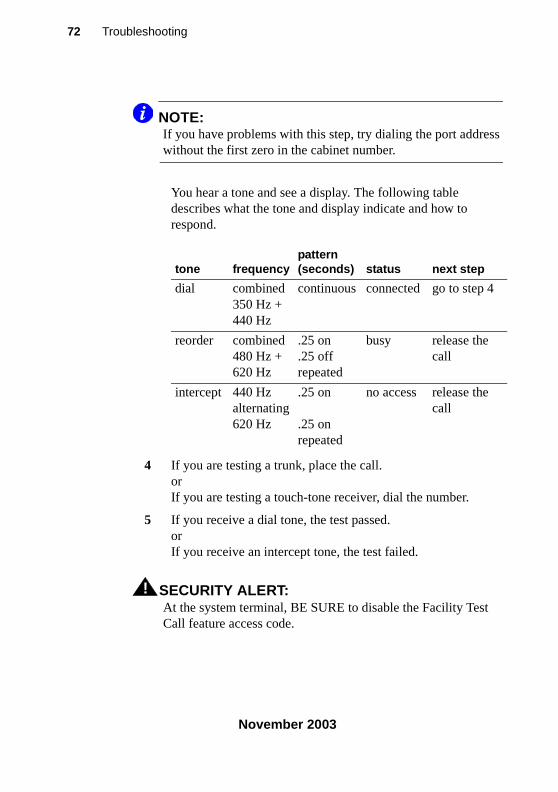
72 Troubleshooting
November 2003
NOTE:If you have problems with this step, try dialing the port address without the first zero in the cabinet number.
You hear a tone and see a display. The following table describes what the tone and display indicate and how to respond.
4 If you are testing a trunk, place the call.orIf you are testing a touch-tone receiver, dial the number.
5 If you receive a dial tone, the test passed.orIf you receive an intercept tone, the test failed.
SECURITY ALERT: !At the system terminal, BE SURE to disable the Facility Test Call feature access code.
tone frequencypattern(seconds) status next step
dial combined350 Hz +440 Hz
continuous connected go to step 4
reorder combined480 Hz +620 Hz
.25 on
.25 offrepeated
busy release the call
intercept 440 Hzalternating620 Hz
.25 on
.25 onrepeated
no access release the call
233758_6.book Page 72 Tuesday, August 5, 2003 6:22 AM
73Using features to troubleshoot
November 2003
feat
ures
Trunk Identification
You can identify a faulty or noisy trunk with Trunk Identification. You can use Trunk Identification:
• on an active call
• while accessing a trunk
To identify the specific trunk used on a call:
1 Press the Trunk ID button.
Trunk access code and trunk group member number appears on the display.
If 2 trunks are used on the call, the identification of the last trunk added to the call displays. If more than 2 trunks are on a call, Trunk Identification is denied.
2 See if there are any on-board alarms against a trunk circuit pack.
If no, report the trunk problem to the appropriate vendor.
If yes, report the trunk problem and the identification information to Avaya.
233758_6.book Page 73 Tuesday, August 5, 2003 6:22 AM

74 Troubleshooting
November 2003
233758_6.book Page 74 Tuesday, August 5, 2003 6:22 AM
75Solving IP and H.323 problems
November 2003
IP &
H.3
23
6 Solving IP and H.323 problems
This section describes some basic troubleshooting tips and tools that may help you solve problems with IP (internet protocol) phones, Softphones, and IP and H.323 trunk issues.
In addition to using this section, you may want to refer to Administration for Network Connectivity for Avaya MultiVantage™ Software, 555-233-504, for basic IP administration.
Solving Softphone problems
This section discusses some common problems you or your users may encounter while using IP Softphones (telecommuter or RoadWarrior types).
NOTE:R1 and R2 IP Softphone and IP Agent, which use a dual connect (two extensions) architecture, are no longer supported. R3 and R4 IP Softphone and IP Agent, which use a single connect (one extension) architecture, continue to be supported. This applies to the RoadWarrior configuration and the Native H.323 configuration for the IP Softphone.
233758_6.book Page 75 Tuesday, August 5, 2003 6:22 AM
76 Solving Softphone problems
November 2003
Users cannot login (register) with IP Softphone
The user’s password needs to be the same as the administered station security code. So, the first thing to verify is whether or not the user is using the correct password. If they are using the correct password, then you should determine if the problem is with their PC.
To determine if the problem is related to the user’s PC, try to register (login) this extension from another PC. If you can successfully register, then the problem is within the user’s PC. If you cannot register, then the extension may not be administered correctly or you may have a network problem.
User is logged in, but cannot use Softphone for calls
If you see the message “Telephony is not available” in the call status area, then you may have COR to COR restrictions between the IP Softphone and the actual hard phone used to make calls.
If you do not have restrictions, then try logging off and back in again. If that fails, reboot the PC that the Softphone is running on.
! WARNING:Some system platforms also run on a PC. If you reboot a system PC that is running a D1, all calls will be lost. In that case, you might want to wait until after normal business hours to reboot the PC.
233758_6.book Page 76 Tuesday, August 5, 2003 6:22 AM
77Solving IP and H.323 problems
November 2003
IP &
H.3
23
Cannot listen to messages withINTUITY Message Manager
When a user is logged in to IP Softphone in the roadwarrior application, the Softphone has control of the PC sound card. Since only one application can control the PC sound card at a time, the sound card will not be available to Message Manager.
Users get message “Action cannot be completed”
The user may have a button on the IP Softphone that is not actually administered on the STATION form for the extension. Or the user is trying to dial a feature access code that is not administered in the system.
User cannot conference or transfer
Both the conference and the transfer operations require at least two lines. Make sure the user has more than one line available to place calls. To determine if the user has more than one line appearance, complete the following steps:
1 At the IP Softphone, select Number of Calls from the Options menu.
2 Verify that the Minimum or Default number of lines to be displayed is more than one.
233758_6.book Page 77 Tuesday, August 5, 2003 6:22 AM
78 Sound quality problems
November 2003
Users cannot use Directory
In order to use the directory, users must have a Directory, Normal, and Next button available.
Other tips
If your users get the message “Communication to the server has been lost. You will be logged off by the server,” the only option is to click OK. However, if the user is active on a call, they can finish the call before they click OK.
Sound quality problems
Because of the myriad of networks and equipment involved in an IP call, there are a lot of factors that may contribute to sound quality problems. This section contains tips for how to determine the source of the problem, and some things you can do that may help.
Isolating problems in the LANor the Communication Manager setup
There are a few easy things you can do to determine if a voice quality problem is in the Communication Manager setup or in your LAN or PC.
To check the PC sound quality, create and play back a sound file using the PC sound recorder. If the sound quality is unacceptable, the problem is somewhere in your headset or sound card.
233758_6.book Page 78 Tuesday, August 5, 2003 6:22 AM
79Solving IP and H.323 problems
November 2003
IP &
H.3
23
To check sound quality over the LAN, shut down IP Softphone. Now start up NetMeeting and initiate a call. This completely bypasses the Communication Manager. Therefore, if you are still experiencing sound quality problems, the source must be somewhere within the LAN. If this resolves the sound quality problem, the issue is with the Communication Manager setup.
NOTE:For more information on NetMeeting, see Microsoft’s Web site at www.microsoft.com.
Running a mute test
The mute test can also help determine the source of a sound quality problem. To run this test, set up an IP softphone test call between two users who are experiencing voice quality problems. Have one user mute their phone and have the other user count aloud to 10. If the sound quality improves, then the problem is in the sound card, microphone, or headset of the muted phone. If the sound quality does not improve, try the test again, but this time mute the other phone.
Checking the PC volume control
Softphone has its own volume controls, but sometimes the volume controls on the PC need to be adjusted. If the PC volume controls are set too loud, it can cause sound quality to be distorted. If the PC volume controls are set too low, it may be difficult to hear clearly. Try adjusting the volume control on the PC to resolve the problem.
233758_6.book Page 79 Tuesday, August 5, 2003 6:22 AM
80 Sound quality problems
November 2003
Checking for packet loss and jitter
Packet loss and jitter can cause a noisy connection that eventually breaks up, creating gaps in the conversation and making speech unintelligible. Use status station to check for station-side IP problems, including problems with an IP phone, and use status trunk to check for trunk-side IP problems.
Each command generates snapshot jitter buffer size (ms) and packet loss report for a particular station or trunk group member that shows:
• the number of packets that are lost or corrupted
• amount of jitter on the connection
In this instance, jitter is the variability in the amount of time (in milliseconds) that packets are received over the network. When jitter increases, the user experiences a noisy connection, delays, and a general loss of quality, making speech unintelligible.
NOTE:If you issue a status station or status trunk command for a non-IP station, or the connection is hairpinned or shuffled, then the packet loss and jitter size information does not appear. See the Administration for Network Connectivity for Avaya MultiVantage™ Software, 555-233-504, for more information.
Other possible causes
If a user is browsing the web while using softphone and they are accessing web sites with large graphics, they may experience an interruption in voice transmission.
233758_6.book Page 80 Tuesday, August 5, 2003 6:22 AM
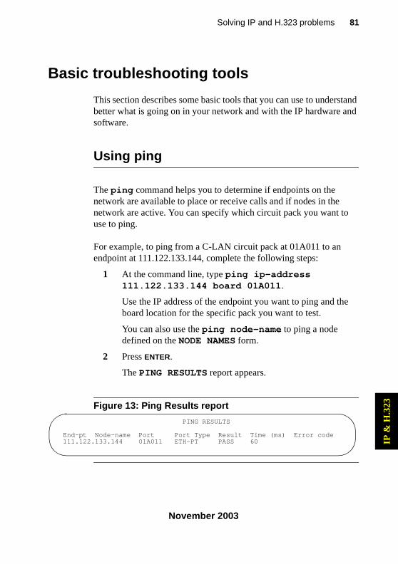
81Solving IP and H.323 problems
November 2003
IP &
H.3
23
Basic troubleshooting tools
This section describes some basic tools that you can use to understand better what is going on in your network and with the IP hardware and software.
Using ping
The ping command helps you to determine if endpoints on the network are available to place or receive calls and if nodes in the network are active. You can specify which circuit pack you want to use to ping.
For example, to ping from a C-LAN circuit pack at 01A011 to an endpoint at 111.122.133.144, complete the following steps:
1 At the command line, type ping ip-address 111.122.133.144 board 01A011.
Use the IP address of the endpoint you want to ping and the board location for the specific pack you want to test.
You can also use the ping node-name to ping a node defined on the NODE NAMES form.
2 Press ENTER.
The PING RESULTS report appears.
Figure 13: Ping Results report
PING RESULTS
End-pt Node-name Port Port Type Result Time (ms) Error code111.122.133.144 01A011 ETH-PT PASS 60
233758_6.book Page 81 Tuesday, August 5, 2003 6:22 AM
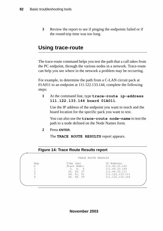
82 Basic troubleshooting tools
November 2003
3 Review the report to see if pinging the endpoints failed or if the round-trip time was too long.
Using trace-route
The trace-route command helps you test the path that a call takes from the PC endpoint, through the various nodes in a network. Trace-route can help you see where in the network a problem may be occurring.
For example, to determine the path from a C-LAN circuit pack at 01A011 to an endpoint at 111.122.133.144, complete the following steps:
1 At the command line, type trace-route ip-address 111.122.133.144 board 01A011.
Use the IP address of the endpoint you want to reach and the board location for the specific pack you want to test.
You can also use the trace-route node-name to test the path to a node defined on the Node Names form.
2 Press ENTER.
The TRACE ROUTE RESULTS report appears.
Figure 14: Trace Route Results report
TRACE ROUTE RESULTS
Hop Time (ms) IP Address0 Start Addr: 111.44.33.1221 5, 6, 6 111.44.33.1442 35, 36, 37 111.44.33.1113 49, 51, 51 111.122.133.1114 58, 58, 59 111.122.133.144
233758_6.book Page 82 Tuesday, August 5, 2003 6:22 AM
83Solving IP and H.323 problems
November 2003
IP &
H.3
23
3 Verify that the last IP address on the report is the same as the IP endpoint you specified in Step 1.
If the system was unable to follow the full path, it lists the last address that it could successfully reach. This information may help you narrow which part of the network is experiencing problems.
Finding the IP address
In some cases, you will want to know the IP address of a PC so that you can ping it or trace the route of a call to it. To determine the IP address, complete the following steps:
1 At the PC, open a Command Prompt (DOS) window.
Typically you can access the command prompt by selecting Start > Programs > Command Prompt.
2 At the Command prompt, type winnt\system32\ipconfig (Windows NT/2000) or winipcfg (Windows 95/98).
3 Record the IP address for the PC.
Verifying the IP Softphone registration
Sometimes you will need to know whether or not an IP Softphone is registered. For example, to determine whether the Softphone at extension 4455 is registered, complete the following steps:
1 Type status station 4455 and press ENTER.
The GENERAL STATUS form appears.
2 Look at the Registration Status field on the second page. If the word “authenticated” appears, the Softphone is registered.
233758_6.book Page 83 Tuesday, August 5, 2003 6:22 AM
84 Basic troubleshooting tools
November 2003
Verifying the trunk type
Sometimes you will need to know whether or not a trunk group is an IP type endpoint. For example, to determine whether the trunk member 01 of trunk group 40 is an IP endpoint, complete the following steps:
1 Type status trunk 40/01 and press ENTER.
The TRUNK STATUS form appears.
2 Verify that the Port field is T000nn.
If this field displays a standard port address (for example, 01A0210), then the trunk is not an IP endpoint.
When all else fails
Reboot the PC. When you are experiencing unexpected behavior that you cannot easily fix, you may want to close all your applications and reboot the machine.
! WARNING:Some system platforms also run on a PC. If you reboot a system PC that is running a D1, all calls will be lost. In that case, you might want to wait until after normal business hours to reboot the PC.
233758_6.book Page 84 Tuesday, August 5, 2003 6:22 AM
85Contacting Avaya
November 2003
cont
acti
ng
7 Contacting Avaya
This section describes what information you should have handy when you need to contact the Avaya Technical Service Center (TSC). This section also provides a list of phone numbers you can call when you have a problem with your system.
Preparing to contact Avaya
Do you need to call Avaya for additional information or help in solving a problem? If you do, please have the following information handy. This helps the person taking your call.
• your name and number (in case we need to call you back)
• your installation location number (also called your IL)
_________________________________________________(Write your IL number here for easy reference)
• your company’s main phone number
• the type of your switch
• the number of trunks on your system
• the number of stations on your system
233758_6.book Page 85 Tuesday, August 5, 2003 6:22 AM
86 Preparing to contact Avaya
November 2003
Also, use the information in this book to determine the possible source of your problem. It always helps to keep a log of the steps you took and the information you gathered while performing your diagnosis. This information is extremely helpful when you partner with an Avaya representative in solving your switch problems.
Remember, if the problem is with equipment or service outside of your own equipment, you need to call your vendor or service provider. If you determine that the problem is with your own equipment, such as on your own stations, switch, or trunks, give Avaya a call.
If you are not sure where the problem is located, double-check your system information. Refer to Problem solving strategies on page 29 for more information.
Be ready to talk about:
• the problem you want to solve
• if the problem is with a new component or feature
• if something that used to work now does not work
• any numbers involved with the problem (for example, extensions or phone numbers, trunk group numbers, phone types, or report types)
• the contents of any recorded messages received
• error messages from the switch
• type of ringback tones received on phones
• the names and numbers of your vendors
• any other pertinent information
233758_6.book Page 86 Tuesday, August 5, 2003 6:22 AM
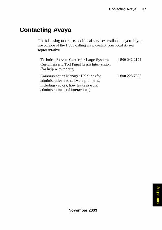
87Contacting Avaya
November 2003
cont
acti
ng
Contacting Avaya
The following table lists additional services available to you. If you are outside of the 1 800 calling area, contact your local Avaya representative.
Technical Service Center for Large-Systems Customers and Toll Fraud Crisis Intervention (for help with repairs)
1 800 242 2121
Communication Manager Helpline (for administration and software problems, including vectors, how features work, administration, and interactions)
1 800 225 7585
233758_6.book Page 87 Tuesday, August 5, 2003 6:22 AM

88 Contacting Avaya
November 2003
233758_6.book Page 88 Tuesday, August 5, 2003 6:22 AM
89Index
November 2003
Index
A
about this book intended audience, 13 purpose, 13
address/location designation circuit packs, 17 media modules, 17
admonishments, 17 alarm buttons, 58 alarm logs, 54 alarms
classifications of, 54 clearing, 57 DS1, 63 off-board, 55 on-board, 55 preventing, 61
Automatic Circuit Assurance (ACA), 66 Avaya support Web site, 20, 21
B
backups, 27 baselining
definition, 23 retrieving information, 24
books how to order more copies, 20
busy-verify hunt groups, 68 trunks, 69
buttons Alarm, 58 Busy Verify, 67 help, 16 Trunk ID, 73
C
cabinet status, viewing, 33 cabinet, definition of, 17 call center, problems, 43 calling Avaya, 85 circuit pack codes, 16 circuit packs, removing, 62 clearing alarms, 57 clearing errors, 53 commands
change circuit-pack, 63 change data-module extension, 61 display alarms, 29, 55 display errors, 29, 50 list history, 34 ping, 81 save announcements, 27 save translations, 27 status, 29 status health, 31 status station, 32, 80 status station extension, 32 status system all-cabinets, 33 status trunk, 80 test station extension, 60 trace-route, 82
233758_6.book Page 89 Tuesday, August 5, 2003 6:22 AM
90 D
November 2003
D
diagnosing problems, 37 dialing out, problems, 39 DS1, alarms, 63
E
error logs interpreting, 53 viewing, 50
error types, 58 1 – circuit pack removed, 61 18 – busied out, 58 513 – equipment missing, 60
errors clearing, 53 preventing, 61
F
Facility Busy Indication, 70 Facility Test Calls, 71 forms, 15
Alarm Report, 56 Alarm Report detail, 57 Data Module, 62 Error Report, 50 General Status, 32 Hardware Error Report, 52, 59, 60 Help, 30 History, 34 Status Health, 31 System Status Cabinet, 33
H
H.323 trunk, 75 help
buttons, 16 numbers to call, 21
history, viewing, 34 hunt groups, busy-verify, 68
I
IL number. See installation location (IL) number
incoming calls, problems, 40 installation location (IL) number, 85 intended audience, 13 internet protocol (IP), 75 IP address, 83 IP Softphone, 75
L
login, problems, 43 logs
alarms, 54 clearing alarms, 57 error, 50
M
maintaining records, 24 Maintenance Objects (MO), 49 message lamp problems, 40 message line, 16 modem problems, 42
233758_6.book Page 90 Tuesday, August 5, 2003 6:22 AM
91Index
November 2003
P
password, problems, 43 phone problems, solving, 38 phones, busy-verify, 67 printer problems, 42 problems
call center, 43 diagnosing, 37 dialing out, 39 incoming calls, 40 login, 43 message lamp, 40 modem, 42 password, 43 phone, 38 printer, 42 SAT, 43 Softphone, 75 sound quality, 78 terminal access, 43 tie trunks, 41 trunks, 41
problem-solving, strategies, 29
R
records, maintaining, 24 removing circuit packs, 62 reports
error, 50 history, 34
S
SAT problems, 43 screens, see forms, 15 security
access codes, 71 concerns, 18
Softphone, 75 solving problems, 75
status cabinet, 33 station, 32 system health, 31
status line, 16 strategies, problem-solving, 29 system backups, 27 system changes, viewing, 34 system health, viewing, 31 system logs
alarms, 49 errors, 49
system status, viewing, 30 system, definition of, 16
T
terminal access, problems, 43 testing
phones, 71 trunks, 71
testing, busy phones, 67 tests, 61 tie trunk problems, 41 toll fraud, 18 trademarks, 18
233758_6.book Page 91 Tuesday, August 5, 2003 6:22 AM
92 U
November 2003
troubleshooting phone problems, 38 trunks, 73 using features, 65
Trunk Identification, 73 trunks
busy-verify, 69 identifying problems, 41, 80 troubleshooting, 73
turning off tests, 61 turning-off, 61
U
UUCSSpp designation, 17
V
viewing error logs, 50 station status, 32 system changes, 34 system status, 30
voice terminals, see phones
W
Web sites Avaya support, 20, 21
X
XXXVSpp designation, 17
233758_6.book Page 92 Tuesday, August 5, 2003 6:22 AM


