Avo CT-160 in use Avo CT-160 in use - last updated 26/08/06 21:34:52 This page contains instructions on how to use the Avo CT-160 portable tube tester. It's a rough guide, no more, but will get you up an running. It will also show you how to test the tubes with no manual. WARNING Warning - the CT-160 generates high voltages which are present within the test area and accessible to the operator. Do not insert or remove tubes with the power switched on. In addition, the mains voltage selector presents mains voltage to the operator if the flap is lifted - there are no safety interlocks. Again, do not adjust the mains voltage taps with the unit switched on. An Example For this example, we will test a 6BQ5/EL84 tube using nothing other than information available in a standard tube manual. In the USA, Essential Characteristics [General Electric] is an excellent book. For UK/European tubes, Radio Valve and Transistor Data [Ball, A.M.] will provide you with plenty of information. If you don't have any tube manuals, you can visit the Tube Data Sheet Locator online which provides sufficient information to test many vacuum tubes. For our example, we will do just that. On the right is the pinout diagram for the 6BQ5. From the TDSL we can obtain some characteristic data on this tube. First the ratings and filament voltages: Vh V Ih A Va max V Vg2 max V Vh-k max V Pa max W Pg2 max W Ik max mA Notes 6.3 0.76 300 300 100 12 2 65 Max Pg2 = 4W for music/speech short term The useful information here, is that Vh (heater or filament voltage is 6.3). Now we need to gather some static test data: Mode Va V Vg2 V Vg1 V Ia mA Ig2 mA Ra Ohms S ma/V Rk Ohms Zout Ohms Pout W THD % A S/E 250 250 -7.3 48 5.5 38,000 11 135 5,200 5.7 10 http://www.duncanamps.com/technical/ct160use.html (1 of 4)28/06/10 3:46:37 PM
Transcript
Avo CT-160 in use
Avo CT-160 in use - last updated 26/08/06 21:34:52
This page contains instructions on how to use the Avo CT-160 portable tube tester. It's a rough guide, no more, but will get you up an running. It will also show you how to test the tubes with no manual.
WARNING
Warning - the CT-160 generates high voltages which are present within the test area and accessible to the operator. Do not insert or remove tubes with the power switched on.
In addition, the mains voltage selector presents mains voltage to the operator if the flap is lifted - there are no safety interlocks. Again, do not adjust the mains voltage taps with the unit switched on.
An Example
For this example, we will test a 6BQ5/EL84 tube using nothing other than information available in a standard tube manual. In the USA, Essential Characteristics [General Electric] is an excellent book. For UK/European tubes, Radio Valve and Transistor Data [Ball, A.M.] will provide you with plenty of information.
If you don't have any tube manuals, you can visit the Tube Data Sheet Locator online which provides sufficient information to test many vacuum tubes.
For our example, we will do just that. On the right is the pinout diagram for the 6BQ5.
From the TDSL we can obtain some characteristic data on this tube. First the ratings and filament voltages:
Vh V
Ih A
Va max V
Vg2 max V
Vh-k max V
Pa max W
Pg2 max W
Ik max mA Notes
6.3 0.76 300 300 100 12 2 65 Max Pg2 = 4W for music/speech short term
The useful information here, is that Vh (heater or filament voltage is 6.3). Now we need to gather some static test data:
Mode
Va V
Vg2 V
Vg1 V
Ia mA
Ig2 mA
Ra Ohms
S ma/V
Rk Ohms
Zout Ohms
Pout W
THD %
A S/E 250 250 -7.3 48 5.5 38,000 11 135 5,200 5.7 10 http://www.duncanamps.com/technical/ct160use.html (1 of 4)28/06/10 3:46:37 PM
Only the first three lines are of interest, the remainder are for push-pull applications. The first line provides some class A static conditions which will be ideal for our test purposes.
Testing preamp and power tubes
1. Setting up. With the power switched off, plug the tube to be tested into an appropriate socket, and set all of the following switches.
2a. Circuit switch. Ensure this is on "Set~".
2b. Pinout thumbwheel switches. These must be set to match the pinout of the tube. There are nine thumbwheel switches which correspond to up to 9 pins on a tube. Please ignore the numbers on the thumbwheel switches - they are not the tube pin numbers!
Running through the nine switches, we get the following mapping onto the 6BQ5 pinout:
Switch Setting
1 [O] (open circuit)
2 [4G] G = grid
3 [1C] C = cathode
4 [2H-] H- = heater -
5 [3H+] H+ = heater +
6 [O]
7 [6A] A = anode (plate)
8 [O]
9 [5S] S = screen
Again, ignoring the numbers on the wheels (they are for correlation with the handbook), the markings around each thumbwheel are [O] = Open circuit, [1C] = Cathode, [2H-] = Heater-, [3H+] = Heater+, [4G] = Grid, [5S] = Screen, [6A] = Anode (plate), [7A2] = Anode2, [8D1] = Diode anode 1, [9D2] = Diode anode 2.
http://www.duncanamps.com/technical/ct160use.html (2 of 4)28/06/10 3:46:37 PM
Avo CT-160 in use
You will notice A1 and A2 links within the test area. These are for putting resistors in while testing magic eye tubes. Careful, the links are "hot".
2c. Voltages. Set the neg grid volts, heater volts, anode volts and screen volts to appropriate values. From the table above, these would be -7.3, 6.3, 250 and 250. Take care with the toggle switch above the heater voltage selector - this flips in a whole different set of heater voltages.
2d. Current. The CT-160 (and other Avo tube testers) measure current by using a bridge method. The two current switches are set to where you think the current will be, then adjusted to balance the bridge - more on this later. In the meantime, we are looking for 48mA or thereabouts, so set the units dial to 8 and the tens dial to 40.
3 Power up. Switch on the mains supply, and wait for the unit to stabilise for a couple of minutes. At the top of the meter is a red ~ at the end of the scale. This is the calibration point. Should it read a little low after warming up, switch off and knock the mains tap down to the next lower voltage. Equally, if it is reading high, then knock it up a little.
Note that if the meter is reading really low, and you feel that the mains voltage is about right, then your CT-160 may be in need of repair or service. Don't tap down any further than what you believe is a reasonable value for your local mains supply.
4a. Heater continuity. Rotate the circuit selector to H/CONT. This will test the heater continuity. If the meter drops down to zero, then you have an open circuit heater. Bye bye tube...
4b. Electrode insulation. Ensure the electrode selector is at A1 (for anode 1), and rotate the circuit selector to A/R. this measures the insulation between the Anode/Rest of the electrodes. You can read the number of megohms of insulation of the dial. Treat any movement with total suspicion. Flip between A1 and A2 for twin triodes etc.
Rotate the circuit selector to S/R (Screen/Rest) and C.H/R (Cathode+Heater/Rest). Again, there should be no noticeable movement of the meter.
4c. Cathode/Heater insulation. Rotate the circuit selector to C/H (Cathode/Heater) - the tube heater will be energised at this point. Keep an eye on the meter as the tube warms up.
You will have to use your own judgement on what is acceptable as leakage between cathode and heater. 0.25meg might be acceptable for a power tube in a fixed-bias configuration, but no good for a cascode amplifier.
4d. Anode current. When the tube has warmed up for a couple of minutes, rotate the circuit selector to TEST. At this point, the high voltages will be applied to the tube. If the buzzer sounds and the dial lights up red, then there is likely a fault with the tube (like grid shorted to cathode) - check this with a multimeter.
If the tube lights up like a firework or UV lamp, then it's full of gas - throw it away...
Balancing the bridge - at this point, our desire is to have the meter reading zero. That's right, zero! If the meter goes off the right hand side of the scale, increase the current units/tens switches to compensate. If the meter goes off the left hand side of the scale, reduce the current switches.
Hover around zero, and let the tube stabilise for a little longer. This is especially important if a power tube is being tested, as the internal structure will move around a little due to the increase heat from having B+ applied. Make minor adjustments to the current as necessary, and finally read the current off the two current controls, not the meter!
http://www.duncanamps.com/technical/ct160use.html (3 of 4)28/06/10 3:46:37 PM
Avo CT-160 in use
4e. Mutual conductance. Or gm, or transconductance - an important measure of the effectiveness of a tube to amplify a signal. Assuming that the current from step 4d is in the right ball park, rotate the Set ma/V dial slightly so that the pointer is in the set zero range. This intensifies the sensitivity of the bridge, and while holding in this position, make further fine adjustments to the current controls to bring back our zero balance.
In our 6BQ5 example, we are looking for around 11 mA/V on a good tube. Continue to rotate the Set mA/V dial round to correspond to 11 on the dial - this is somewhere between the markings of 10.0 and 12.5 on the dial.
The meter needle will rise, and you can use the Replace and Good indicators on the meter to give an indication of the effectiveness of the tube. If you want to measure gm more accurately, alter the Set mA/V dial to a point where the meter needle lines up with 1mA/V above the Good section. Simply read the actual gm off the Set mA/V dial.
4f. Gas test. Release the Set mA/V dial and rotate the circuit selector to Gas. The lowest scale on the meter shows the amount of grid current. Note that it is not unusual for preamp tubes to go slightly negative at this point.
5. Finishing off. If the tube contained two devices (e.g. 12AX7), repeat steps 4d to 4f with the electrode selector set to A2.
Finally, rotate the circuit selector back round to Set~ and switch off. The tube will be hot, especially if a power tube, so take care when removing it.
Testing Rectifiers
This is a little different, and is a more basic go/no go test. Ignore the anode screen and grid voltages, and make absolutely sure that the pinouts correspond to D1 and D2 not A1 and A2. Set the silver portion of the current dial to a test current for the rectifier, and hit test.
http://www.duncanamps.com/technical/ct160use.html (4 of 4)28/06/10 3:46:37 PM
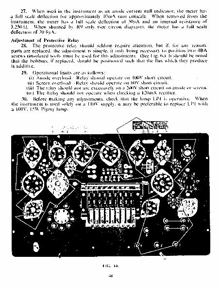
NOTES FOR THE USE OF AVO CT160 VALVE TEST METER FROM THE UK MILITARY MANUAL AP117L-0101-1(Pt.2), ALSO KNOWN AS BR1171(13)B.
What follows in the manual is 106 pages of valve set up data for the CT160 which I have not scanned!