58
AVR 435 Power for the Digital Revolution ® AVR 435 Audio/ Video Receiver OWNER’S MANUAL
| Date post: | 12-Dec-2015 |
| Category: |
Documents |
| Upload: | homofaberhu |
| View: | 220 times |
| Download: | 0 times |

AVR 435
Power for the Digital Revolution®
AVR 435 Audio/VideoReceiverOWNER’S MANUAL

2 TABLE OF CONTENTS
3 Introduction4 Safety Information4 Unpacking5 Front Panel Controls7 Rear Panel Connections
10 Main Remote Control Functions14 Zone II Remote Control Functions15 Installation and Connections15 Audio Connections15 Video Connections16 SCART A/V Connections18 System and Power Connections19 Speaker Selection19 Speaker Placement20 System Configuration20 First Turn On20 Using the On-Screen Display20 System Setup20 Input Setup21 Audio Setup22 Surround Setup23 Night Mode Settings23 Using EzSet/EQ26 Manual Setup26 Speaker Setup28 Speaker Crossover Setting29 Delay Settings30 Output Level Adjustment33 Operation33 Surround Mode Chart35 Basic Operation35 Source Selection35 6/8-Channel Direct Input35 Controls and Use of Headphones36 Surround Mode Selection36 Digital Audio Playback36 Dolby Digital37 DTS37 PCM Audio Playback37 MP3 Audio Playback38 Selecting a Digital Source38 Digital Bitstream Indicators38 Speaker/Channel Indicators39 Night Mode39 Tape Recording40 Output Level Adjustment
With Source Signals40 Dim Function40 Memory backup41 Advanced Features41 Front Panel Display Fade41 Display Brightness41 Turn-On Volume Level41 Semi-OSD Settings42 Full-OSD Time Out Adjustment42 Digital Auto-Poll Settings42 Multiroom Operation44 Tuner Operation44 Basic Tuner Operation44 Station Selection44 Preset Tuning45 RDS Operation45 RDS Tuning45 RDS Display Options45 Program Search
Table of Contents
Typographical ConventionsIn order to help you use this manual with the remote control, front-panel controls and rear-panelconnections, certain conventions have been used.
EXAMPLE – (bold type) indicates a specific remote control or front-panel button, or rear-panel connection jack
EXAMPLE – (OCR type) indicates a message that is visible on the front-panel information display
EXAMPLE – (Synchro type) indicates a message that is displayed on the remote control’s LCD screen
1 – (number in a square) indicates a specific front-panel control
� – (number in a circle) indicates a rear-panel connection
0 – (number in an oval) indicates a button or indicator on the remote
å – (letter in an oval) indicates a button on the Zone II remote
46 Programming the Remote46 Preprogrammed Code Entry47 Automatic Code Entry47 Learning Commands48 Learning Remote Codes for an Input
Selector48 Device Priority48 Changing Devices49 Macro Programming51 Punch-Through Configuration
52 Renaming54 Resetting the Remote54 Backlight Options56 Troubleshooting Guide56 Processor Reset57 Technical Specifications
Declaration of Conformity
We, Harman Consumer Group International2, route de Tours72500 Château-du-Loir,FRANCE
declare in own responsibility, that the product describedin this owner’s manual is in compliance with technicalstandards:
EN 55013:2001+A1:2003
EN 55020:2002+A1:2003
EN 61000-3-2:2000
EN 61000-3-3.1995+A1:2001
EN 60065:2002
Jurjen AmsterdamHarman Consumer Group International
01/05
The appearance of the text or cursor for your receiver’s on-screen menus may vary slightly from the illustrations inthis manual. Whether the text appears in all uppercase or upper- and lowercase characters, performance andoperation remain the same.

INTRODUCTION 3
Introduction
Thank you for choosing Harman Kardon! With the purchase of a Harman Kardon AVR 435you are about to begin many years of listeningenjoyment.
Designed to provide all the excitement and detailof movie soundtracks and every nuance of musi-cal selections, the AVR 435 is truly a multichan-nel receiver for the new millennium. In additionto the traditional 5.1 digital decoding modessuch as Dolby Digital and DTS, it offers the latestadvancements in surround technology such asDolby Pro Logic IIx, the full suite of DTS-ES 6.1modes, DTS Neo:6 and the latest 7.1 channelversions of Harman's own Logic 7 technology.
The AVR 435 has been engineered so that it iseasy to take advantage of all the power of itsdigital technology. To obtain the maximumenjoyment from your new receiver, we urge youto read this manual. A few minutes spentlearning the functions of the various controlswill enable you to take advantage of all thepower the AVR is able to deliver.
If you have any questions about this product, itsinstallation or its operation, please contact yourretailer or custom installer. They are your bestlocal sources of information.
Description and FeaturesThe AVR 435 is among the most versatile andmultifeatured A/V receivers available, incorporat-ing a wide range of listening options. In additionto Dolby Digital and DTS decoding for digitalsources, a broad choice of surround modes forMatrix surround-encoded or Stereo recordingsare available for use with sources such as CD,VCR, TV broadcasts and the AVR’s own FM/AMtuner. Along with Dolby Digital EX, DTS-ES®,Dolby Pro Logic IIx, DTS Neo:6, Dolby 3 Stereo,5 Channel or 7 Channel Stereo and Hall andTheater modes, the AVR 435 offers HarmanInternational’s exclusive Logic 7 process in both5.1 and 7.1 versions to create a wider, moreenveloping field environment and more definedfly-overs and pans. Although the AVR 435’sprimary use will be in multichannel systems,advanced technology is at work even when onlytwo speakers are used. Dolby Virtual Speaker isavailable to create enveloping sound fields fromfront left and right speakers, and the latest DolbyHeadphone circuitry creates an amazing sense ofopenness with headphones.Two-channel listening with analog sources isavailable with full bass management or in a tra-ditional “bypass” mode that creates a straightsignal path from the gain stage to the volumecontrol.
Finally, the AVR is among the very few A/Vreceivers that offer decoding of MP3 data, sothat you may listen to the latest music selectionsdirectly from compatible computers or playbackdevices with the power and fidelity you expectfrom Harman Kardon.
An important addition to the AVR 435’s impres-sive list of features is EzSet/EQ,™ which auto-mates the configuration process to make itquicker, easier and more precise. Using the spe-cial microphone supplied with the unit, EzSet/EQtakes the guesswork out of entering speaker“size” and crossover information, delay times forall channels and output levels. In addition to theconfiguration settings, EzSet/EQ also includesroom equalization so that the signals sent toeach speaker are tailored to provide accuratesonic quality with your specific combination ofspeaker type, room size and other factors thatinfluence room acoustics. With EzSet/EQ, yoursystem is custom-configured in a few minuteswith accuracy that previously required expensiveand hard-to-use test equipment.
In tandem with EzSet/EQ, the AVR 435 includes afull set of manual configuration settings forthose who wish to custom-trim their system evenfurther. A Quadruple Crossover bass manage-ment system makes it possible to enter differentcrossover settings for each speaker group.
Video connections and system integration is asnap with the AVR 435. For those sourcesalready in component form, three assignable,wide-bandwidth inputs are available, and theVideo inputs are renameable. To further enhancethe viewing experience with digital sources ordisplays, the AVR 435’s A/V Sync Delay featureallows you to compensate for the loss of lip syncdue to digital video delays individually for eachinput. A bi-directional RS-232 port and a learn-ing remote with a two-line display are amongthe many other features that make theAVR 435’s power simple to use.
Coax and optical digital outputs are available fordirect connection to digital recorders, and twovideo recording outputs, preamp-out and a color-coded eight-channel input make the AVR virtual-ly future-proof, with everything needed toaccommodate tomorrow’s new formats right onboard.
The AVR 435’s flexibility and power extendbeyond your main home theater or listeningroom. The AVR includes a sophisticated multi-zone control system that allows you to selectone source for use in the main room and a dif-ferent one (Audio only) in a second room.Complete control over volume is possible with aseparate infrared control link. To make it easy tooperate the AVR from a remote room, a separate
“Zone II” remote is included.Additional multiroom options include the optionto assign two of the AVR’s output channels to themultiroom system and the ability to link the AVRto innovative A-BUS® keypads for multiroom oper-ation without the need for external amplifiers.
The AVR 435’s powerful amplifier uses traditionalHarman Kardon high-current design technologiesto meet the wide dynamic range of any programselection.
Harman Kardon invented the high-fidelityreceiver more than fifty years ago. With state-of-the-art circuitry and time-honored circuit designs,the AVR is the perfect combination of the latest indigital audio technology, a quiet yet powerfulanalog amplifier in an elegant, easy-to-usepackage.
� Dolby* Digital, Dolby Digital EX andDolby Pro Logic* IIx Decoding, and thefull suite of DTS® modes, including DTS-ES® 6.1 Discrete & Matrix andNeo:6® and DTS 96/24
� Seven channels of high-current amplifi-cation with two channels assignable toeither surround back or multiroomapplications
� Harman Kardon’s exclusive Logic 7®
processing, along with a choice ofDolby Virtual Speaker processing foruse when only two speakers areavailable
� Dolby Headphone to create spacious,open sound fields when using head-phones
� MP3 decoding for use with compatiblecomputers and digital audio players
� Harman Kardon’s advanced EzSet/EQ™automatically configures speaker set-tings and sets room equalization forquick, easy and accurate system setup
� High-bandwidth, HDTV-compatible com-ponent video switching
� Front panel analog A/V inputs
� Front panel digital inputs for easy con-nection to portable digital devices andthe latest video game consoles
� Multiple digital inputs and outputs
� On-screen menu and display system
� Extensive multiroom options, includinga standard Zone II remote, assignableamplifier channels and A-BUS Ready®
capability for listening to a separatesource in a remote zone
� 6-Channel/8-Channel Direct Input and

4 INTRODUCTION / SAFETY INFORMATION
Introduction / Safety Information
Preamp Outputs for Easy Expansion andUse with Future Audio Formats
� Extensive bass management options,6/8-channel direct inputs for use withDVD-Audio or SACD players, includingQuadruple Crossover and individualsettings for each input
� A/V Sync delay adjustable for eachinput delivers perfect lip sync withdigital programs or video displays
� Main Backlit Remote with InternalCodes and Learning Capability
Important Safety Information
Verify Line Voltage Before UseYour AVR 435 has been designed for use with220-240-Volt AC current. Connection to a linevoltage other than that for which it is intendedcan create a safety and fire hazard and maydamage the unit.
If you have any questions about the voltagerequirements for your specific model, or aboutthe line voltage in your area, contact your dealerbefore plugging the unit into a wall outlet.
Do Not Use Extension CordsTo avoid safety hazards, use only the power cordattached to your unit. We do not recommendthat extension cords be used with this product.As with all electrical devices, do not run powercords under rugs or carpets or place heavyobjects on them. Damaged power cords shouldbe replaced immediately by an authorized serv-ice depot with a cord meeting factory specifica-tions.
Handle the AC Power Cord GentlyWhen disconnecting the power cord from an ACoutlet, always pull the plug, never pull the cord.If you do not intend to use the unit for anyconsiderable length of time, disconnect the plugfrom the AC outlet.
Do Not Open the CabinetThere are no user-serviceable components insidethis product. Opening the cabinet may present ashock hazard, and any modification to the prod-uct will void your guarantee. If water or anymetal object such as a paper clip, wire or astaple accidentally falls inside the unit, discon-nect it from the AC power source immediately,and consult an authorized service station.
Installation Location� To assure proper operation and to avoid the
potential for safety hazards, place the unit ona firm and level surface. When placing theunit on a shelf, be certain that the shelf andany mounting hardware can support theweight of the product.
� Make certain that proper space is providedboth above and below the unit for ventilation.If this product will be installed in a cabinet orother enclosed area, make certain that thereis sufficient air movement within the cabinet.Under some circumstances a fan may berequired.
� Do not place the unit directly on a carpetedsurface.
� Avoid installation in extremely hot or coldlocations, or an area that is exposed to directsunlight or heating equipment.
� Avoid moist or humid locations.
� Do not obstruct the ventilation slots on thetop of the unit, or place objects directly overthem.
CleaningWhen the unit gets dirty, wipe it with a clean,soft, dry cloth. If necessary, wipe it with a softcloth dampened with mild soapy water, then afresh cloth with clean water. Wipe dry immedi-ately with a dry cloth. NEVER use benzene,aerosol cleaners, thinner, alcohol or any othervolatile cleaning agent. Do not use abrasivecleaners, as they may damage the finish of metalparts. Avoid spraying insecticide near the unit.
Moving the UnitBefore moving the unit, be certain to disconnectany interconnection cords with other compo-nents, and make certain that you disconnect theunit from the AC outlet.
Unpacking
The carton and shipping materials used to pro-tect your new receiver during shipment werespecially designed to cushion it from shock andvibration. We suggest that you save the cartonand packing materials for use in shipping if youmove, or should the unit ever need repair.
To minimize the size of the carton in storage,you may wish to flatten it. This is done by care-fully slitting the tape seams on the bottom andcollapsing the carton. Other cardboard insertsmay be stored in the same manner. Packingmaterials that cannot be collapsed should besaved along with the carton in a plastic bag.
If you do not wish to save the packaging materi-als, please note that the carton and other sec-tions of the shipping protection are recyclable.Please respect the environment and discardthose materials at a local recycling center.

FRONT PANEL CONTROLS 5
1 Main Power Switch: Press this button toapply power to the AVR. When the switch ispressed in, the unit is placed in a Standbymode, as indicated by the orange LED 3surrounding the System Power Control 2.This button MUST be pressed in to operate theunit. To turn the unit off completely and preventthe use of the remote control, this switchshould be pressed until it pops out from thefront panel so that the word “OFF” may be read at the top of the switch.NOTE: This switch is normally left in the “ON”position.
2 System Power Control: When the MainPower Switch 1 is “ON,” press this button toturn on the AVR; press it again to turn the unitoff (to Standby). Note that the Power Indicatorsurrounding the switch 3 will turn blue whenthe unit is on.
3 Power Indicator: This LED will be illuminated in orange when the unit is in theStandby mode to signal that the unit is ready tobe turned on. When the unit is in operation, theindicator will turn blue.
4 Headphone Jack: This jack may be used tolisten to the AVR’s output through a pair of head-phones. Be certain that the headphones have astandard 6.3 mm stereo phone plug. Note thatthe main room speakers and all PreampOutputs � will automatically be turned offwhen the headphone jack is in use.
5 Surround Mode Group Selector: Press thisbutton to select the top-level group of surroundmodes. Each press of the button will select amajor mode grouping in the following order:
Dolby Modes ➜ DTS Digital Modes ➜ DSPModes ➜ Stereo Modes ➜ Logic 7 Modes
Once the button is pressed so that the name ofthe desired surround mode group appears in theon-screen display and in the Lower Display Line˜, press the Surround Mode Selector 9 tocycle through the individual modes available. Forexample, press this button to select Dolby modes,and then press the Surround Mode Selector9 to choose from the various mode options.
6 Speaker Selector: Press this button tobegin the process of configuring the AVR for thetype of speakers it is being used with. For com-plete information on configuring the speaker set-tings using the front-panel controls see page 27.
7 ‹ Button: When an adjustment is beingmade using the Channel Select Ù or DigitalSelect Û buttons, this button may be pressedto scroll through the available options.
8 Tone Mode: Pressing this button enables ordisables the Balance, Bass and Treble tone controls. When the button is pressed so that thewords TONEIN appear in the Main Infor-mation Display ˜, the settings of the Bassand Treble controls and of the Balance controlwill affect the output signals. When the button ispressed so that the words TONEOUT appearin the Main Information Display ˜, theoutput signal will be “flat,” without any balance,bass or treble alteration, no matter how theactual Controls are adjusted. (For more infor-mation, see page 22).
Front Panel Controls
1234 5 67 8 9 )!
@ # $ % ^ & * ( Ó Ô
Ò Ú Û Ù ı ˆ ˜ ¯
Main Power SwitchSystem Power ControlPower IndicatorHeadphone JackSurround Mode Group SelectorSpeaker Selector‹ ButtonTone ModeSurround Mode SelectorTuning SelectorTuner Band Selector
Set ButtonPreset Station Selector› ButtonInput Source SelectorRDS SelectorDelay Adjust SelectorDigital Optical 4 InputEzSet/EQ Microphone JacksDigital Coax 4 JackVideo 4 Input/Output JacksFront Panel Control Door
Surround Mode IndicatorsSpeaker/Channel Input IndicatorsDigital Select ButtonChannel Select ButtonVolume ControlInput IndicatorsMain Information DisplayRemote Sensor Window
3
2 1 4 5 8
9 ) ! # % ^
6 Ù Û & 7 @ $ ( * Ó Ô
Ò ˜ Ú ˆ¯ ı
AVR 435

6 FRONT PANEL CONTROLS
Front Panel Controls
9 Surround Mode Selector: Press thisbutton to cycle through the individual surroundmodes available after the Surround ModeGroup Selector 5 was pressed (see item 5above). Note that depending on the type ofinput, some modes are not always available. (Seepage 36 for more information about surroundmodes).
) Tuning Selector: Press the left side of thebutton to tune lower frequency stations and theright side of the button to tune higher frequencystations. When a station with a strong signal isreached, MANUALTUNED or AUTOTUNEDwill appear in the Main InformationDisplay ˜ (see page 44 for more informationon tuning stations).
! Tuner Band Selector: Pressing this buttonwill automatically switch the AVR to the Tunermode. Pressing it again will switch between theAM and FM frequency bands, holding it pressedfor some seconds will switch between stereo andmono receiving and between automatic andmanual tuning mode (See page 44 for moreinformation on the tuner).
@ Set Button: When making choices during the setup and configuration process, press thisbutton to enter the desired setting as shown inthe Main Information Display ˜ into theAVR’s memory.
# Preset Stations Selector: Press thisbutton to scroll up or down through the list ofstations that have been entered into the presetmemory. (See page 44 for more information ontuner programming.)
$ › Button: When an adjustment is beingmade using the Channel Select Ù or DigitalSelect Û buttons, this button may be pressedto scroll through the available options.
% Input Source Selector: Press this button tochange the input by scrolling through the list ofinput sources.
^ RDS Select Button: Press this button to dis-play the various messages that are part of the RDSdata system of the AVR’s tuner. (See page 45 formore information on RDS).
& Delay Adjust Selector: Press this button tobegin the process of adjusting the delay settingsfor Dolby surround modes. See page 29 for moreinformation on delay adjustments.
* Digital Optical 4 Input: Connect the opticaldigital audio output of an audio or video productto this jack. When the Input is not in use, be certain to keep the plastic cap installed to avoiddust contamination that might degrade future performance.
( EzSet/EQ Microphone Jack: Beforestarting the EzSet/EQ automated setup process,plug the microphone into this jack. The micro-phone does not need to be plugged in at othertimes.
Ó Digital Coax 4 Jack: This jack is normallyused for connection to the output of portableaudio devices, video game consoles or otherproducts that have a coax digital jack.
Ô Video 4 Input/Output Jacks: Theseaudio/video jacks may be used for temporaryconnection to video games or portable audio/video products such as camcorders and portableaudio players.
Front-Panel Control Door: To open thedoor so that the front-panel jacks and controlsbehind this door may be accessed, gently pull thedoor down and towards you using either uppercorner of the door.
Ò Surround Mode Indicators: The currentselected mode or function will appear as one ofthese indicators. Note that when the unit isturned on, the entire list of available modes willlight briefly, and then revert to normal operationwith only the active mode indicator illuminated.
Ú Speaker/Channel Input Indicators: Theseindicators are multipurpose, indicating either thespeaker type selected for each channel or theincoming data-signal configuration. The left, center,right, right surround and left surround speakerindicators are composed of three boxes, while thesubwoofer is a single box. The center box lightswhen a “Small” speaker is selected, and the twoouter boxes light when “Large” speakers areselected. When none of the boxes are lit for thecenter, surround or subwoofer channels, no speakerhas been selected for that position. (See page 27for more information on configuring speakers.) Theletters inside each of the center boxes displayactive input channels. For standard analog inputs,only the L and R will light, indicating a stereoinput. When a digital source is playing, the indica-tors will light to display the channels beginreceived at the digital input. When the lettersflash, the digital input has been interrupted. (Seepage 38 for more information on the ChannelIndicators).
Û Digital Select Button: When playing asource that has a digital output, press this buttonto select between the Optical *� andCoaxial Ó� Digital inputs (See page 36 formore information).
Ù Channel Select Button: Press this buttonto begin the process of trimming the channeloutput levels using an external audio source.(For more information on output level trimadjustment, see page 40).
ı Volume Control: Turn this knob clockwiseto increase the volume, counterclockwise todecrease the volume. If the AVR is muted,adjusting volume control will automaticallyrelease the unit from the silenced condition.
ˆ Input indicators: The current selectedmode or function will appear as one of theseindicators. Note that when the unit is turned on,the entire list of available modes will light briefly,and then revert to normal operation with onlythe active mode indicator illuminated.
˜ Main Information Display: This displaydelivers messages and status indications to helpyou operate the receiver.
¯ Remote Sensor Window: The sensorbehind this window receives infrared signals fromthe remote control. Aim the remote at this areaand do not block or cover it unless an externalremote sensor is installed.

REAR PANEL CONNECTIONS 7
Rear Panel Connections
230 V/50Hz
�
� � � � � �� � � � � � � �
� � � � � � � � � � � !
" � # $ % & ' ( ) * +,
~230V/50Hz
�"�#���$� �!&(
%*+,������ ����
�������) � ' � �
AM AntennaFM AntennaTape InputsTape OutputsSubwoofer OutputDVD Audio InputsCD InputsMultiroom OutputsA-BUS Connector8-Channel Direct InputsDigital Audio OutputsVideo Monitor OutputsDVD Video InputsFront Speaker OutputsCenter Speaker Outputs
Surround Speaker OutputsSwitched AC Accessory OutletUnswitched AC Accessory OutletAC Power Cord JackVideo 2 Component Video InputsComponent Video OutputsVideo 1 Component Video InputsRemote IR OutputRemote IR InputMultiroom IR InputVideo 1 Video OutputsVideo 1 Video InputsVideo 2 Video OutputsVideo 3 Video InputsVideo 2 Video Inputs
Optical Digital InputsCoaxial Digital InputsVideo 2 Audio OutputsVideo 2 Audio InputsVideo 3 Audio InputsVideo 1 Audio InputsVideo 1 Audio OutputsPreamp OutputsSurround Back/Multiroom Speaker OutputsRS-232 PortFan VentsDVD Component Video InputsRemote IR Carrier Output
NOTE: To assist in making the correct connec-tions for multichannel input/output and speakerconnections, all connection jacks and terminalshave been color coded in conformance with thelatest CEA standards as follows:Front Left: WhiteFront Right: RedCenter: GreenSurround Left: BlueSurround Right: GraySurround Back Left: BrownSurround Back Right: TanSubwoofer (LFE): PurpleDigital Audio: OrangeComposite Video: YellowComponent Video “Y”: GreenComponent Video “Pr”: RedComponent Video “Pb”: Blue
� AM Antenna: Connect the AM loop antennasupplied with the receiver to these terminals. If anexternal AM antenna is used, make connections tothe AM and GND terminals in accordance withthe instructions supplied with the antenna.
" FM Antenna: Connect the supplied indoor oran optional external FM antenna to this terminal.
Tape Inputs: Connect these jacks to thePLAY/OUT jacks of an audio recorder.
� Tape Outputs: Connect these jacks to theRECORD/INPUT jacks of an audio recorder.
# Subwoofer Output: Connect this jack tothe line-level input of a powered subwoofer. If anexternal subwoofer amplifier is used, connect thisjack to the subwoofer amplifier input.
� DVD Audio Inputs: Connect these jacks tothe analog audio jacks on a DVD or other audioor video source.
� CD Inputs: Connect these jacks to the analog output of a compact disc player or CDchanger or any other audio source.
� Multiroom Outputs: Connect these jacksto an optional audio power amplifier to listen tothe source selected by the multiroom system in aremote room.
$ A-BUS Connector: Connect this jack to anoptional A-BUS-certified remote room keypad oramplifier to extend the multiroom capabilities ofyour AVR. See page 18 for more information onA-BUS.
� 8-Channel Direct Inputs: These jacks areused for connection to source devices such asDVD-Audio or SACD players with discrete analogoutputs. Depending on the source device in use,all eight jacks may be used, though in manycases only connections to the front left/right,center, surround left/right and LFE (subwooferinput) jacks will be used for standard 5.1 audiosignals.
Digital Audio Outputs: Connect thesejacks to the matching digital input connector ona digital recorder such as a CD-R or MiniDiscrecorder.

8 REAR PANEL CONNECTIONS
Rear Panel Connections
� Video Monitor Outputs: Connect this jackto the composite and/or S-Video input of a TVmonitor or video projector to view the on-screenmenus and the output of any standard Video orS-Video source selected by the receiver’s videoswitcher.
! DVD Video Inputs: Connect these jacks tothe composite or S-Video output jacks on a DVDplayer or other video source.
& Front Speaker Outputs: Connect theseoutputs to the matching + or – terminals onyour left and right speakers. In conformance withthe new CEA color code specification, the Whiteterminal is the positive, or "+" terminal thatshould be connected to the red (+) terminal onFront Left speaker with the older color coding,while the Red terminal is the positive, or "+"terminal that should be connected to the red (+)terminal on Front Right speaker. Connect theblack (–) terminals on the AVR to the black (–)terminals on the speakers. See page 15 for moreinformation on speaker polarity.
( Center Speaker Outputs: Connect theseoutputs to the matching + and – terminals onyour center channel speaker. In conformancewith the new CEA color code specification, theGreen Terminal is the positive, or "+" terminalthat should be connected to the red (+) terminalon speakers with the older color coding. Connectthe black (–) terminal on the AVR to the blacknegative (–) terminal on your speaker. (See page15 for more information on speaker polarity.)
% Surround Speaker Outputs: Connectthese outputs to the matching + and – terminalson your surround channel speakers. In confor-mance with the new CEA color code specifica-tion, the Blue terminal is the positive, or "+"terminal that should be connected to the red (+)terminal on the Surround Left speaker with oldercolor coding, while the Gray terminal should beconnected to the red (+) terminal on theSurround Right speaker with the older color cod-ing. Connect the black (–) terminal on the AVRto the matching black negative (–) terminals foreach surround speaker. (See page 15 for moreinformation on speaker polarity.)
* Switched AC Accessory Outlet: This out-let may be used to power any device that youwish to have turn on when the AVR is turned onwith the System Power Control switch 2.
+ Unswitched AC Accessory Outlet: Thisoutlet may be used to power any AC device. Thepower will remain on at this outlet regardless ofwhether the AVR is on or off (in Standby), pro-vided that the Main Power switch 1 is on.
Note: The total power consumption of alldevices connected to the accessory outletsshould not exceed 100 watts from theUnswitched Outlet + and 50 W from theSwitched Outlet *.
, AC Power Cord Jack: Connect the ACpower cord to this jack when the installation iscomplete. To ensure safe operation, use only thepower cord supplied with the unit. If a replace-ment is required it must be of the same type andcapacity.
� Component Video 2 Inputs: These inputsmay be used with any video source deviceequipped with analog Y/Pr/Pb or RGB com-ponent video outputs. The factory default is forthese jacks to be a linked to the Video 2 input,but you may change the setting at any timethrough the IN/OUTSETUPmenu. Seepage 15 for more information on configuring thecomponent video inputs.
� Monitor Component Video Outputs:Connect these outputs to the component videoinputs of a video projector or monitor. When asource connected to one of the twoComponent Video Inputs �� is selectedthe signal will be sent to these jacks.
� Component Video 1 Inputs: These inputsmay be used with any source device equippedwith analog Y/Pr/Pb or RGB component videooutputs. The factory default is for these jacks tobe a linked to the Video 1 input, but you maychange the setting at any time through theIN/OUTSETUPmenu. See page 15 formore information on configuring the componentvideo inputs.
Note: All component inputs/outputs can beused for RGB signals too, in the same way asdescribed for the Y/Pr/Pb signals, then connectedto the jacks with the corresponding color.RGB connection is not possible if the source out-puts a separate sync signal (see page 16).
� Remote IR Output: This connection permitsthe IR sensor in the receiver to serve otherremote controlled devices. Connect this jack tothe “IR IN” jack on Harman Kardon or othercompatible equipment.
� Remote IR Input: If the AVR’s front-panelIR sensor is blocked due to cabinet doors orother obstructions, an external IR sensor maybe used. Connect the output of the sensor tothis jack.
� Multiroom IR Input: Connect the output ofan IR sensor in a remote room to this jack tooperate the AVR’s multiroom control system.
Video 1 Video Outputs: Connect thesejacks to the RECORD/INPUT composite or S-Video jack on a VCR.
� Video 1 Video Inputs: Connect these jacksto the PLAY/OUT composite or S-Video jacks ona VCR or other video source.
� Video 2 Video Outputs: Connect thesejacks to the RECORD/INPUT composite or S-Video jacks on a second VCR.
� Video 3 Video Inputs: Connect these jacksto the PLAY/OUT composite or S-Video jacks onany video source.
� Video 2 Video Inputs: Connect these jacksto the PLAY/OUT composite or S-Video jacks ona second VCR or other video source.
Optical Digital Inputs: Connect the optical digital output from a DVD player, HDTVreceiver, the S/PDIF output of a compatible com-puter sound card playing MP3 files or streams,LD player, MD player or CD player to these jacks.The signal may be either a Dolby Digital signal, aDTS signal, a 2 channel MPEG 1 signal or MP3data stream or a standard PCM digital source.
� Coaxial Digital Inputs: Connect the coaxdigital output from a DVD player, HDTV receiver,the S/PDIF output of a compatible computersound card playing MP3 files or streams, LDplayer, MD player or CD player to these jacks.The signal may be either a Dolby Digital signal,DTS signal, a 2 channel MPEG 1 signal or MP3data stream or a standard PCM digital source.Do not connect the RF digital output of an LDplayer to these jacks.
� Video 2 Audio Outputs: Connect thesejacks to the RECORD/INPUT audio jacks on aVCR or any Audio recorder.
� Video 2 Audio Inputs: Connect these jacksto the PLAY/OUT audio jacks on a second VCRor other audio or video source.
� Video 3 Audio Inputs: Connect these jacksto the PLAY/OUT audio jacks on any audio orvideo source.
� Video 1 Audio Inputs: Connect these jacksto the PLAY/OUT audio jacks on a VCR or otheraudio or video source.
� Video 1 Audio Outputs: Connect thesejacks to the RECORD/INPUT audio jacks on a VCR or any other Audio recorder.
REAR PANEL CONNECTIONS 9
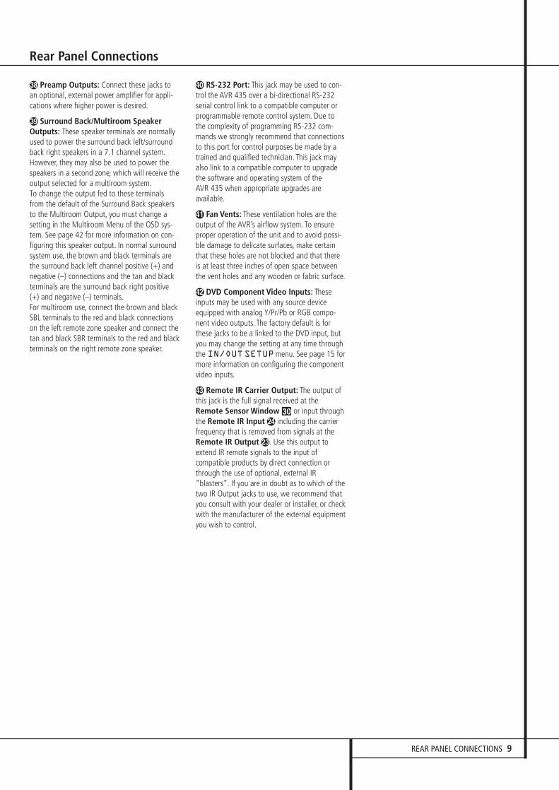
� Preamp Outputs: Connect these jacks toan optional, external power amplifier for appli-cations where higher power is desired.
) Surround Back/Multiroom SpeakerOutputs: These speaker terminals are normallyused to power the surround back left/surroundback right speakers in a 7.1 channel system.However, they may also be used to power thespeakers in a second zone, which will receive theoutput selected for a multiroom system.To change the output fed to these terminalsfrom the default of the Surround Back speakersto the Multiroom Output, you must change asetting in the Multiroom Menu of the OSD sys-tem. See page 42 for more information on con-figuring this speaker output. In normal surroundsystem use, the brown and black terminals arethe surround back left channel positive (+) andnegative (–) connections and the tan and blackterminals are the surround back right positive(+) and negative (–) terminals.For multiroom use, connect the brown and blackSBL terminals to the red and black connectionson the left remote zone speaker and connect thetan and black SBR terminals to the red and blackterminals on the right remote zone speaker.
� RS-232 Port: This jack may be used to con-trol the AVR 435 over a bi-directional RS-232serial control link to a compatible computer orprogrammable remote control system. Due tothe complexity of programming RS-232 com-mands we strongly recommend that connectionsto this port for control purposes be made by atrained and qualified technician. This jack mayalso link to a compatible computer to upgradethe software and operating system of the AVR 435 when appropriate upgrades areavailable.
' Fan Vents: These ventilation holes are theoutput of the AVR’s airflow system. To ensureproper operation of the unit and to avoid possi-ble damage to delicate surfaces, make certainthat these holes are not blocked and that thereis at least three inches of open space betweenthe vent holes and any wooden or fabric surface.
� DVD Component Video Inputs: Theseinputs may be used with any source deviceequipped with analog Y/Pr/Pb or RGB compo-nent video outputs. The factory default is forthese jacks to be a linked to the DVD input, butyou may change the setting at any time throughthe IN/OUTSETUPmenu. See page 15 formore information on configuring the componentvideo inputs.
� Remote IR Carrier Output: The output ofthis jack is the full signal received at theRemote Sensor Window ¯ or input throughthe Remote IR Input � including the carrierfrequency that is removed from signals at theRemote IR Output �. Use this output toextend IR remote signals to the input ofcompatible products by direct connection orthrough the use of optional, external IR“blasters”. If you are in doubt as to which of thetwo IR Output jacks to use, we recommend thatyou consult with your dealer or installer, or checkwith the manufacturer of the external equipmentyou wish to control.
Rear Panel Connections

0123456789ABCDEFGHIJKLMNOPQ��� !"#$%&'()*+,-
10 MAIN REMOTE CONTROL FUNCTIONS
Main Remote Control Functions
Power Off ButtonIR Transmitter WindowLCD Information DisplayPower On ButtonInput SelectorsAVR SelectorAM/FM Tuner Select6-Channel/8-Channel Direct InputTest ButtonSleep ButtonSurround Mode SelectorNight ModeChannel Select ButtonDim ButtonNavigation ButtonSet ButtonDigital SelectNumeric KeysTuner ModeDirect ButtonTuning Up/DownOSD ButtonDolby Mode Select ButtonDTS Digital Mode SelectorLogic 7 Mode Select ButtonTransport ControlsLight ButtonSkip Up/Down ButtonsStereo Mode Select ButtonDTS Neo:6 Mode SelectMacro ButtonsRDS Selector ButtonPreset Up/DownClear ButtonMemory ButtonDelay/Prev. Ch.Program ButtonSpeaker SelectMultiroomVolume Up/DownVideo Input ButtonChannel Up/Down SelectorMuteTone Control Button
NOTE: The function names shown here are eachbutton’s feature when used with the AVR. Mostbuttons have additional functions when usedwith other devices.
The jack on the upper right side of the remote isreserved for future use. Do not remove the plugprovided or connect any device to the jack.
0
2
5
A
J
H
D
E
F
P
�
&
(
B
-
6
P
'
�
N
7
9
L
K
+
%
$
�
M
,
1
3
4
8
O
#
I
C
G
)
P
"
!
Q
MUTE
*

MAIN REMOTE CONTROL FUNCTIONS 11
Main Remote Control Functions
IMPORTANT NOTE: The AVR 435’s remote maybe programmed to control up to seven devices,including the AVR. Before using the remote, it isimportant to remember to press the InputSelector button 4 that corresponds to theunit you wish to operate. In addition, the AVR’sremote is shipped from the factory to operate theAVR and most Harman Kardon CD or DVD play-ers and cassette decks. The remote is also capa-ble of operating a wide variety of other productsusing the control codes that are part of theremote or by learning commands from otherremotes. Before using the remote with otherproducts, follow the instructions on pages 46-49to program the proper codes for the products inyour system.
It is also important to remember that many ofthe buttons on the remote take on different functions, depending on the product selectedusing the Input Selector Button 4. Thedescriptions shown here primarily detail thefunctions of the remote when it is used tooperate the AVR.
0 Power Off Button: Press this button toplace the AVR or a selected device unit in theStandby mode. Note that when the AVR isswitched off this will turn off the main room functions, but if the Multiroom system is activated,it will continue to function.
1 IR Transmitter Window: Point this windowtowards the AVR when pressing buttons on theremote to make certain that infrared commandsare properly received.
2 LCD Information Display: This two-linescreen displays various information dependingon the commands that have been entered intothe remote.
3 Power On Button: Press this button to turnon the power to a device selected by pressing oneof the Input Selectors 4 (except Tape).
4 Input Selectors: Pressing one of thesebuttons will perform three actions at the sametime. First, if the AVR is not turned on, this willpower up the unit. Next, it will select the sourceshown on the button as the input to the AVR.Finally, it will change the remote control so thatit controls the device selected. After pressing oneof these buttons you must press the AVRSelector button 5 again to operate the AVR’sfunctions with the remote.
5 AVR Selector: Pressing this button willswitch the remote so that it will operate the AVR’sfunctions. If the AVR is in the Standby mode, it willalso turn the AVR on.
6 AM/FM Tuner Select: Press this button toselect the AVR’s tuner as the listening choice.Pressing this button when the tuner is in use willselect between the AM and FM bands.
7 6-Channel/8 Channel Direct Input:Press this button to select the device connectedto the 6-Channel Direct Inputs or the 8-Channel Direct Inputs � (the input available will depend on the selection 5.1 or6.1/7.1 made in the surround mode setting,see page 24 for more information).
8 Test Tone: Press this button to begin thesequence used to calibrate the AVR’s output lev-els. (See page 27 for more information on calibrat-ing the AVR.)
9 Sleep Button: Press this button to placethe unit in the Sleep mode. After the time shownin the display, the AVR will automatically go intothe Standby mode. Each press of the buttonchanges the time until turn-off in the followingorder:
Hold the button pressed for two seconds to turnoff the Sleep mode setting.Note that this button is also used to changechannels on your TV, VCR and Sat receiver whenthe appropriate source is selected, using thedevice Input Selectors 4.
A Surround Mode Selector: Press this but-ton to select any of the HALL, THEATER surroundmodes. Note that depending on the type ofinput, some modes are not always available. (Seepage 33 for more information about surroundmodes.) Note that this button is also used totune channels on your TV, VCR and Sat receiverwhen the appropriate source is selected usingthe device Input Selector 4.
B Night Mode: Press this button to activatethe Night mode. This mode is available only withDolby Digital encoded sources, and it preservesdialog (center channel) intelligibilty at low vol-ume levels (See page 23 for more information).
C Channel Select Button: This button isused to start the process of setting the AVR’soutput levels with an external source. Once thisbutton is pressed, use the ⁄/¤ buttons E toselect the channel being adjusted, then press theSet button F, followed by the ⁄/¤ buttonsE again, to change the level setting. (See page40 for more information.)
D Dim Button: Press this button to activatethe Dimmer function, which reduces the bright-ness of the front-panel display, or turns it offentirely. Press the button once to change the dis-play to reduce the brightness by 50%, and pressit again within five seconds and the main display
will go completely dark. Note that this setting istemporary; regardless of any changes, the displaywill always return to full brightness when theAVR is turned on. The blue illumination aroundthe Standby/On Button 1 will always remainat full brightness regardless of the setting toremind you that the AVR is still turned on. Theblue accent lighting inside the volume controlwill also remain at full brightness when thepanel is at 50%, but go out when the panellights are fully dimmed.
E Navigation Button: This single disc-likebutton is used to change or scroll through itemsin the on-screen menus or on the front panel orto make configuration settings such as digitalinputs or delay timing. When changing a setting,first press the button for the function or settingto be changed (e.g., press the Digital SelectButton G to change a digital input) and thenpress one of these buttons to scroll through thelist of options or to increase or decrease a set-ting. The sections in this manual describing theindividual features and functions contain specificinformation on using these buttons for eachapplication.
F Set Button: This button is used to enter settings into the AVR’s memory. It is also used inthe setup procedures for delay time, speaker con-figuration and channel output level adjustment.
G Digital Select: Press this button to assignone of the digital inputs �*Ó to a source.(See page 37 for more information on using digital inputs.)
H Numeric Keys: These buttons serve as aten-button numeric keypad to enter tuner presetpositions. They are also used to select channelnumbers when TV, VCR or Sat receiver hasbeen selected on the remote, or to select tracknumbers on a CD, DVD or LD player, dependingon how the remote has been programmed.
I Tuner Mode: Press this button when thetuner is in use to select between automatictuning and manual tuning. When the button ispressed so MANUAL appears in the MainInformation Display ˜, pressing the Tuningbuttons K) will move the frequency up ordown in single-step increments. When the FMband is in use and AUTO appears in the MainInformation Display ˜, pressing this buttonwill change to monaural reception making evenweek stations audible. (See page 44 for moreinformation.)
J Direct Button: Press this button when thetuner is in use to start the sequence for directentry of a station’s frequency. After pressing thebutton simply press the proper Numeric KeysH to select a station (See page 44 for moreinformation on the tuner).
90min
80min
70min
60min
50min
40min
30min
20min
10min OFF

12 MAIN REMOTE CONTROL FUNCTIONS
K Tuning Up/Down: When the tuner is in use,these buttons will tune up or down through theselected frequency band. If the Tuner Mode but-ton I has been pressed or the Band button! on the front panel was held pressed so thatAUTO appears in the Main InformationDisplay ˜, pressing either of the buttons willcause the tuner to seek the next station withacceptable signal strength for quality reception.When the MANUAL appears in the MainInformation Display ˜, pressing these but-tons will tune stations in single-step increments.(See page 44 for more information.)
L OSD Button: Press this button to activatethe On Screen Display (OSD) system used to setup or adjust the AVR’s parameters.
M Dolby Mode Selector: This button is usedto select one of the available Dolby Surround processing modes. Each press of this button willselect one of the Dolby Pro Logic II modes, Dolby3 Stereo or Dolby Digital. Note that the DolbyDigital mode is only available with a digital inputselected and the other modes only as long as aDolby Digital source is not playing (except ProLogic II with Dolby Digital 2.0 recordings, seeNote on page 7). See page 23 for the availableDolby surround mode options.
N DTS Digital Mode Selector: When a DTSsource is in use the AVR will select the appropri-ate mode automatically and no other mode willbe available. Pressing this button will display themode currently selected by the AVR´s decoder,depending on the surround material played andthe speaker setting (see item 6, page 5). Whena DTS source is not in use, this button has nofunction. (See page 23, 33 for the available DTSoptions.)
O Logic 7 Selector: Press this button toselect one of the available Logic 7 surroundmodes. (See page 33 for the available Logic 7options.)
P Transport Control Buttons: These but-tons do not have any functions for the AVR, butthey may be programmed for the forward/reverseplay operation of a wide variety of CD or DVDplayers, and audio or video- cassette recorders.(See page 46 for more information on program-ming the remote.)
Q Light Button: Press this button to activatethe remote’s built-in backlight for better legibilityof the buttons in a darkened room.
� Skip Up/Down Buttons: These buttons donot have a direct function with the AVR, butwhen used with a compatibly programmed CD orDVD player/changer they will change the trackson the disc currently being played.
� Stereo Mode Selector: Press this buttonto select a stereo playback mode. When the but-ton is pressed so that DSPSURROFFappears in the Main Information Display ˜,the AVR will operate in a bypass mode with truefully analog, two-channel left/right stereo modewith no surround processing or bass manage-ment as opposed to other modes where digitalprocessing is used. When the button is pressedso that SURROUNDOFF appears in theMain Information Display ˜, you may enjoya two-channel presentation of the sound alongwith the benefits of bass management. Whenthe button is pressed so that 5 CHSTEREOor 7 CHSTEREO appears, the stereo signalis routed to all five speakers, if installed. (Seepage 24 for more information on stereo playbackmodes).
� DTS Neo:6 Mode Selector: Pressing thisselector button cycles the AVR through the various DTS Neo:6 modes, which extract a five-or seven-channel surround field from two-chan-nel program material (from PCM source or ana-log input signal). The first press selects the lastDTS Neo:6 surround mode that was in use, andeach subsequent press selects the next mode inthe following order:
Macro Buttons: Press these buttons tostore or recall a “Macro”, which is a pre-pro-grammed sequence of commands stored in theremote. (See page 49 for more information onstoring and recalling macros.)
! RDS Select Button: Press this button todisplay the various messages that are part of theRDS data system of the AVR’s tuner. (See page 45for more information on RDS).
" Preset Up/Down: When the tuner is inuse, press these buttons to scroll through thestations programmed into the AVR’s memory.When CD or DVD is selected using the InputSelector button 4, these buttons may func-tion as Slow Fwd/Rev (DVD) or ”+10” (CD,CDR).
# Clear Button: Press this button to clearincorrect entries when using the remote to directlyenter a radio station’s frequency.
$ Memory Button: Press this button to entera radio station into the AVR’s preset memory. Twounderline indicators will flash at the right side ofthe Main Information Display ˜, you thenhave five seconds to enter a preset memorylocation using the Numeric Keys H. (Seepage 44 for more information.)
% Delay Select Button: This button selectsadjustments to the A/V Sync Delay and the indi-vidual channel displays. The first press of the but-ton displays an A/VSYNCDELAYmessagein the Lower Display Line ˜ and in the on-screen display, which means that you maychange the amount of time that all channels aredelayed together behind the video. This enablesyou to compensate for the loss of lip sync thatmay be caused by digital video processing inyour display or by television stations. To changethe A/V Sync Delay, press the Set Button Fwhile the A/VSYNCDELAYmessage isvisible and then use the ⁄/¤ NavigationButton E to change the setting so that thesound and the video image are in sync. Tochange the delay for an individual output chan-nel, press the ⁄/¤ Navigation Button Euntil the desired channel name is shown, andthen press the Set Button F. Use the ⁄/¤
Navigation Buttons E to change the delayamount. (See page 29 for more information ondelay options.)
& Program Button: This button is used tobegin the process of programming the remote.Press and hold this button for three seconds toplace the remote in the programming mode.Once the red LED under the Set Button Flights, release the button. You may then selectfrom the desired option. (See pages 46-54 formore information on configuring the remote.)
' Speaker Select: Press this button to beginthe process of configuring the AVR’s BassManagement System for use with the type ofspeakers used in your system. Once the buttonhas been pressed, use the ⁄/¤ buttons E toselect the channel you wish to set up. Press theSet Button F and then select the speakertype (Large, Small or None) appropriate with thespeaker in use. (See page 27 for more informa-tion.)
( Multi-Room: Press this button to activatethe Multiroom system or to begin the process ofchanging the input or volume level for the sec-ond zone. (See page 42 for more information onthe Multiroom system.)
)Volume Up/Down: Press these buttons toraise or lower the system volume.
DTS Neo:6 MUSIC
DTS Neo:6 MOVIES
Main Remote Control Functions

MAIN REMOTE CONTROL FUNCTIONS 13
Main Remote Control Functions
* VDI Button: This button does not have anyfunction for the AVR, but is provided for your usein programming the codes that are used to scrollup or down through the available inputs on yourvideo display. This allows you to switch videoinputs that are directly connected to your videodisplay. Alternatively, you may program any com-patible remote code into the “up” and “down”portions of this button. For information on“learning” remote codes into a button on theAVR remote, follow the instructions shown on page 48.
+ Channel Up/Down Selector: This buttonhas no function when the AVR is being con-trolled, but when programmed for use with aVCR, TV, cable box, satellite receiver or othersimilar product it will change the channel up ordown. See pages 46-54 for more information onprogramming the remote.
, Mute: Press this button to momentarilysilence the AVR or TV set being controlled,depending on which device has been selected.When the AVR remote is being programmed tooperate another device, this button is pressed withthe Input Selector button 4 to begin theprogramming process. (See page 46 for moreinformation on programming the remote.)
- Tone Control Button: This button controlsthe tone mode settings, enabling adjustment ofthe bass and treble boost/cut. You may also useit to take the tone controls out of the signal pathcompletely for “flat” response. The first press ofthe button displays a TONEINmessage inthe Lower Display Line ˜ and in the on-screen display. To take the controls out of thesignal path press either of the ⁄/¤ NavigationButtons E until the display reads TONEOUT. To change the bass or treble settings,press the button again until the desired optionappears in the Lower Display Line ˜ and inthe on-screen display and then press either ofthe ⁄/¤ Navigation Buttons E to enter thedesired boost or cut setting. See page 22 formore information on the tone controls.
NOTE: With the press of any remote button theInput Selector button 45 associatedwith the botton pressed will briefly flash red toconfirm the transmission of the command, aslong as there is a function for that button withthe device selected.

14 ZONE II REMOTE CONTROL FUNCTIONS
Zone II Remote Control Functions
å Power Off∫ AVR Selectorç AM/FM Tuner Select∂ Input Selectors≠ Tuning Up/Down – Fast Playƒ Record/Pause© Preset/Track Skip˙ Disc Skipî Volume Up/Down∆ Play Forward/Reverse/StopK Mute
NOTE: The Zone II remote may be used in eitherthe same room where the AVR is located, or itmay be used in a separate room with an option-al infrared sensor that is connected to the AVR’sMulti IR input jack f. When it is used in thesame room as the AVR, it will control the func-tions of the AVR or any compatible HarmanKardon products in that room. When it is used ina separate room via a sensor connected to theMulti IR Jack f, the buttons for power, inputsource, volume and mute will control the source
and volume for the second zone, as connectedto the Multi Out Jacks •. (See page 42 forcomplete information on using the Multiroomsystem.)
The Zone II remote may be used in either thesame room where the AVR is located, or it maybe used in a separate room with an optionalinfrared sensor that is connected to the AVR’sMulti IR input jack �.
å Power Off: When used in the room wherethe AVR is located, press this button to place theunit in Standby. When it is used in a remoteroom with a sensor that is connected to theMulti IR jack �, this button turns the Multi-Room system off.
∫ AVR Selector: Press this button to turn onthe AVR. The input in use when the unit was laston will be selected.
ç AM/FM Tuner Select: Press this button toselect the Tuner as the input to the Multiroomsystem. Press it again to change between theAM and FM bands.
∂ Input Selectors: When the AVR is off,press one of these buttons to turn the unit onand to select a specific input. When the unit isalready in use, pressing one of these buttons willchange the input.
≠ Tuning Up/Down – Fast Play: These but-tons may be used to change the frequency ofthe tuner. These buttons may also control theFast Play or Fast Reverse functions of compatibleHarman Kardon CD, DVD or cassette decks inthe same room, or from a remote room when anIR link is connected to the AVR.
ƒ Record/Pause: Press this button to acti-vate the Record or Pause function on compatibleHarman Kardon CD, DVD or Cassette Deckproducts.
© Preset Up/Down – Track Skip: When theAVR’s tuner is selected as the input source, thesebuttons will move up or down through the list ofstations that have been stored in the presetmemory. When a CD or DVD player is selected,these buttons activate the forward or reversetrack or chapter skip functions.
˙ Disc Skip: Press this button to changediscs on compatible Harman Kardon CD or DVDchangers.
î Volume Up/Down: When used in theroom where the AVR is located, press this buttonto raise or lower the volume in that room. Whenit is used in a remote room with a sensor that isconnected to the Multi IR Jack �, this buttonwill raise or lower the volume in the remoteroom.
∆ Play Forward/Reverse/Stop: Press thesebuttons to control compatible Harman KardonCD, DVD or cassette players.
K Mute: When used in the room where theAVR is located, press this button to temporarilysilence the unit. When it is used in a remoteroom with a sensor that is connected to theMulti IR Jack �, this button will temporarilysilence the feed to the remote room only. Pressthe button again to return to the previous vol-ume level.Important Note: No matter in which room theZone II remote is used, as with the main remoteit is important to remember to press the InputSelector button ∂ that corresponds to theunit you wish to operate befor you change thedevice to be controlled.
POWER
OFF
MUTE
AVR
AM//FM
VID 1
VID 3
DVD CD TAPE
DN TUNING
PRESET
VOLUME
DISC SKIP
DISC SKIP
UPDN
UP
VID 4
VID 2
G
A
B
C
D
E
F
H
I
K
J

INSTALLATION AND CONNECTIONS 15
After unpacking the unit, and placing it on a solidsurface capable of supporting its weight, you willneed to make the connections to your audio andvideo equipment.
Audio Equipment Connections
We recommend that you use high-quality inter-connect cables when making connections tosource equipment and recorders to preserve theintegrity of the signals.
When making connections to audio sourceequipment or speakers it is always a good practice to unplug the unit from the AC wall outlet. This prevents any possibility ofaccidentally sending audio or transient signals tothe speakers that may damage them.
1. Connect the analog output of a CD player tothe CD inputs �.
NOTE: When the CD player has both fixed andvariable audio outputs it is best to use the fixedoutput unless you find that the input to thereceiver is so low that the sound is noisy, or sohigh that the signal is distorted.
2. Connect the analog Play/Out jacks of a cas-sette deck, MD, CD-R or other audio recorder tothe Tape Input jacks . Connect the analogRecord/In jacks on the recorder to the TapeOutput jacks � on the AVR.
3. Connect the digital output of any digitalsources such as a CD or DVD changer or player,advanced video game, a digital satellite receiver,HDTV tuner or digital cable set-top box or theoutput of a compatible computer sound card tothe Optical and Coaxial Digital Inputs�*Ó.
4. Connect the Coaxial or Optical DigitalOutputs on the rear panel of the AVR to thematching digital input connections on a CD-R orMiniDisc recorder.
5. Assemble the AM Loop Antenna supplied withthe unit as shown below. Connect it to the AMand GND screw terminals �.
6. Connect the supplied FM antenna to the FM(75 ohm) connection ". The FM antenna maybe an external roof antenna, an inside poweredor wire lead antenna or a connection from acable system. Note that if the antenna or connec-tion uses 300-ohm twin-lead cable, you shoulduse a 300-ohm-to-75-ohm adapter to make theconnection.
7. Connect the front, center and surroundspeaker outputs &(%) to the respectivespeakers.
To assure that all the audio signals are carried toyour speakers without loss of clarity or resoluti-on, we suggest that you use high-quality speakercable. Many brands of cable are available andthe choice of cable may be influenced by the dis-tance between your speakers and the receiver,the type of speakers you use, personal prefer-ences and other factors. Your dealer or installer isa valuable resource to consult in selecting theproper cable.
Regardless of the brand of cable selected, we recommend that you use a cable constructed offine, multistrand copper with an area greater than2 mm2.
Cable with an area of 1.5 mm2 may be used forshort runs of less than 4 m. We do not recom-mend that you use cables with an area less than1mm2 due to the power loss and degradation inperformance that will occur.
Cables that are run inside walls should have theappropriate markings to indicate listing with anyappropriate testing agency standards. Questionsabout running cables inside walls should bereferred to your installer or a licensed electricianwho is familiar with the applicable local buildingcodes in your area.
When connecting wires to the speakers, be cer-tain to observe proper polarity. Note that thepositive (+) terminal of each speaker connectionnow carries a specific color code as noted onpage 7. However, most speakers will still use ared terminal for the postive (+) connection. Con-nect the “negative” or “black” wire to the sameterminal on both the receiver and the speaker.
NOTE: While most speaker manufacturersadhere to an industry convention of using blackterminals for negative and red ones for positive,some manufacturers may vary from this configu-ration. To assure proper phase and optimal per-formance, consult the identification plate on yourspeaker or the speaker’s manual to verify polarity.If you do not know the polarity of your speaker,ask your dealer for advice before proceeding, orconsult the speaker’s manufacturer.
We also recommend that the length of cableused to connect speaker pairs be identical. Forexample, use the same length piece of cable toconnect the front-left and front-right or sur-round-left and surround-right speakers, even ifthe speakers are a different distance from theAVR.
8. Connections to a subwoofer are normallymade via a line level audio connection from theSubwoofer Output # to the line-level inputof a subwoofer with a built-in amplifier. When apassive subwoofer is used, the connection first
goes to a power amplifier, which will be connect-ed to one or more subwoofer speakers. If you areusing a powered subwoofer that does not haveline-level input connections, follow the instruc-tions furnished with the speaker for connectioninformation.
9. If an external multi-channel audio source with5.1 or 7.1 outputs such as an external digitalprocessor/decoder, DVD-Audio or SACD player isused, connect the outputs of that device to the8-Channel Direct Inputs �.
Video Equipment Connections
Video equipment is connected in the same manneras audio components. Again, the use of high-quality interconnect cables is recommended topreserve signal quality.
1. Connect a VCR’s audio and video Play/Outjacks to the Video 1 or Video 2 In jacks ���� on the rear panel. The Audio and VideoRecord/In jacks on the VCR should be connectedto the Video 1 or Video 2 Out jacks ��� on the AVR.
2. Connect the analog audio and video outputsof a satellite receiver, cable TV converter or televi-sion set or any other video source to the Video3 �� jacks.
3. Connect the analog audio and video outputsof a DVD or laser disc player to the DVD jacks�! .
4. Connect the digital audio outputs of a CD, MDor DVD player, satellite receiver, cable box orHDTV converter to the appropriate Optical orCoaxial Digital Inputs �*Ó.
NOTE: When connecting a device such as a digi-tal cable box or other set-top tuner product witha digital audio output, we recommend that youconnect both the digital and analog outputs ofthe product to your AVR. The audio input pollingfeature of the AVR will then be able to make cer-tain that you have a constant audio feed, since itwill automatically switch the audio input to theanalog jacks if the digital feed is interrupted ornot available for a particular channel.
If your system requires direct connection of avideo source to your display, we suggest that youconsider programming the VDI Buttons * sothat you may change the input used by your dis-play from the AVR’s remote. For information on“learning” remote codes into a button on theAVR remote, follow the instructions shown onpage 48.
5. Connect the Composite and S-Video (if S-Video device is in use) Monitor Output �jacks on the receiver to the composite and S-Video input of your television monitor or videoprojector.
Installation and Connections

16 INSTALLATION AND CONNECTIONS
Installation and Connections
SCART A/V Connections
For the connections described above your videodevice needs RCA (cinch) connectors or/and S-Video connectors for all Audio and Video signals:Any normal video device (Not SVHS or High 8)for only playback needs 3 RCA jacks, VCRs forrecord and playback even 6 RCA jacks. Any S-Video device (SVHS, High 8) needs 2 RCA(Audio) and 1 S-Video jack (Video), if it´s aplayback unit, or 4 RCA (Audio In/Out) and 2 S-Video (Video In/Out) jacks, if it´s a recordingVCR.
Many european video devices are equipped withRCA (Cinch) or S-Video jacks only partially, notfor all audio and video in/outputs needed asdescribed above, but with a so called Scart orEuro-AV connector (almost rectangular jack with21 pins, see drawings on next page).
In that case the following Scart to Cinchadapters or cables are needed:
• Units for playback, such as satellite receivers,camcorders, DVD or LD players, need anadapter from Scart to 3 RCA plugs, see fig. 1(normal video devices) or from Scart to 2RCA+1 S-Video plugs, see fig. 4 (S-Videodevices).
• HiFi VCRs need an adapter from Scart to 6RCA plugs, see fig. 2 (normal video), or fromScart to 4 Audio+2S-Video jacks, see fig. 5 (S-Video VCR). Read carefully the instructionattached to the adapter to find which of thesix plugs is used for the record signal to theVCR (connect with the AVR´s Out jacks) andfor the playback signal from the VCR (connectwith the AVR´s In jacks). Do not misconnectAudio and Video signals. Don´t hesitate toconsult your dealer, if you are uncertain.
• If you use only normal video devices the TVmonitor needs an adapter from 3 RCA plugsto Scart (fig. 3) only. If also S-Video devices areused an adapter from 2 RCA+1S-Video plugsto Scart is needed additionally (fig. 6),connected to the SCART input on your TV thatis provided for S-Video.
Note that only the video plugs (the "yellow"cinch plug in fig. 3 and the S-Video plug in fig. 6) must be connected to the TV MonitorOutput �, and the volume on the TV must bereduced to minimum.
Important Note for Adapter Cables:If the cinch connectors of the adapter you’ll useare labeled, connect the Audio and Video ”In”plugs with the corresponding Audio and Video”In” jacks on the AVR (and with a VCR connectthe ”Out” plugs to the ”Out” jacks on the AVR).Note that with some adapter types it may bejust turned around: If no signal is audible/ visiblewhen the VCR is playing connect the “Out”plugs to the ”In” jacks on the AVR and turnedaround. If the adapter plugs are not labeled inthat way, pay attention to the signal flow direc-tions as shown in the diagrams above and in theinstruction attached to the adapter. If uncertain,don’t hesitate to consult your dealer.
Important Notes for S-Video connections:1. Only the S-Video In/Out of S-Video devicesmust be connected to the AVR, NOT both,normal video and S-Video In/Outputs (except theTV, see item below).When both connections are made, only the S-Video signal will be viewed on the screen.
2. Like most common AV units the AVR does notconvert the Video signal to S-Video, only viceversa. Thus both connections must be made fromthe AVR to the TV if both, Video and S-Videosources, are used, and the appropriate input onthe TV must be selected.
6. If your DVD Player has Y/Pr/Pb analog compo-nent video outputs, connect them to theComponent DVD Inputs �. Although this setof inputs may be assigned to any of the fourvideo inputs on the AVR 435, the factory defaultis for this input to be assigned to the DVDAudio Inputs � Remember to make a digitalaudio connection between the DVD player andthe AVR, with the Coaxial Digital Input 1 �being the factory default. For information onchanging the input assignments for either thecomponent video jacks or the DVD player’s audioconnection, see page 20.
7. If you have other devices with Y/Pr/Pb or RGBcomponent video outputs, connect the sourcedevice to the Component Video 1 and 2Inputs ��. The audio connections may be toany of the Video Audio Inputs ���Ô orthe Optical or Coaxial Digital Inputs �*Ó. When using either of the ComponentVideo Inputs, make certain that the audio andvideo inputs are properly configured in theIN/OUTSETUPmenu, as described onpage 20.
8. If the component video inputs are used,connect the Component Video Output � tothe component video inputs of your TV, projectoror display device.
9. If you have a camcorder, video game or otheraudio/video device that is connected to the AVRon a temporary, rather than permanent basis,connect the audio, video and digital audio out-puts of that device to the Front Panel Inputs*ÓÔ. A device connected to the Video 4jacks Ô is selected as the Video 4 input, andconnected to the digital jacks *Ó it is selectedas "Optical 4" or "Coaxial 4" input. (See page20 for more information on input configuration.)
Video Connection Notes:• Y/Pr/Pb Component, RGB (see page 17), or
Composite video signals may only be viewed intheir native formats and will not be convertedto the other formats. S-Video signals will beconverted to composite signal. The OSD can beviewed on the TV screen in any case, with Videoor S-Video input selected on the TV.
• When the component video jacks are used, theon-screen menus will not be visible. You mustswitch to the standard composite or S-Videoinput on your TV to view those menus.
• All component inputs/outputs can be used forRGB signals too, in the same way as describedfor the Y/Pr/Pb signals, then connected to thejacks with the corresponding color. But this isonly correct as long as only the three RGBvideo signals are output by the video source,with a sync signal in the "G" signal only, with-out any sync signal output separately by thesource.

INSTALLATION AND CONNECTIONS 17
Installation and Connections
Black
Yellow
Red
Figure 1:SCART/Cinch-Adapter for
playback;signal flow:
SCART � Cinch
Black
Red
Blue
Yellow
Green
White
Figure 2:SCART/Cinch-Adapter for
record and playback;signal flow:
SCART ↔ Cinch
Black
Yellow
Red
Figure 3:Cinch/SCART-Adapter for
playback;signal flow:
Cinch � SCART
Rot
Schwarz
S-Video In
Figure 4:SCART/S-Video Adapter
for playback;signal flow:
SCART � Cinch
Schwarz
Rot
Blau
Gelb
S-Video In
S-Video Out
Figure 5:SCART/S-Video Adapterfor record and playback;
signal flow:SCART ↔ Cinch
Rot
Schwarz
S-Video Out
Figure 6:SCART/S-Video Adapter
for playback;signal flow:
Cinch � SCART
Black
Yellow
Red
Black
Red
Blue1
Yellow
Green1
White
Black
Yellow
Red
Red
Black
S-Video In
Red
Black
S-Video Out
Black
Red
Blue1
Yellow
S-Video In
S-Video Out
1 Also other colours possible, e.g. brown and grey.
Important Note for the Use of SCART-Cinch Adapters:When video sources are connected to the TVdirectly with a SCART cable, specific controlsignals apart from Audio/Video signals will befed to the TV. These specific signals are: With allvideo sources, the signal for automatic inputselection that switches the TV automatically tothe appropriate input as soon as the videosource is started. And with DVD players, thesignals automatically turning the TV to 4:3/16:9format (with 16:9 TVs or with 4:3 TVs withselectable 16:9 format) and turning the RGBvideo decoder of the TV on or off, depending onthe DVD player´s setting. With any adapter cable,these control signals will be lost and theappropriate setting of the TV must be mademanually.
Note for RGB signal with SCART:If you use a unit providing RGB signals on aSCART output (as e.g. most DVD players do) andyou want to use that RGB signal, this SCARToutput must be connected directly to your TV.Although the AVR can switch three-way videosignals (like component signals Y/Pb/Pr), mostTVs need separate sync signals for RGB (alsowith SCART) that cannot be switched and pro-vided by the AVR.RGB signals can be pathed through the AVR onlywhen no separate sync signal is needed (see last”Video Connection Note” on page 16).

18 INSTALLATION AND CONNECTIONS
System and Power ConnectionsThe AVR 435 is designed for flexible use withmultiroom systems, external control componentsand power amplifiers.
Main Room Remote Control ExtensionIf the receiver is placed behind a solid or smokedglass cabinet door, the obstruction may preventthe remote sensor from receiving commands. Inthis event, the remote sensor of any HarmanKardon or other compatible device, not coveredby the door, or an optional remote sensor maybe used. Connect the Remote IR Output ofthat device or the output of the remote sensor tothe Remote IR Input jack �.
If other components are also prevented fromreceiving remote commands, only one sensor isneeded. Simply use this unit’s sensor or a remoteeye by running a connection from the RemoteIR Output jack � to the Remote IR Inputjack on Harman Kardon or other compatibleequipment.
Multiroom IR LinkThe key to remote room operation is to link theremote room to the AVR’s location with wire foran infrared receiver and speakers or an amplifier.The remote room IR receiver (this can be anoptional IR receiver or any other remotableHarman Kardon device in the remote room withIR sensor integrated) should be connected to theAVR via standard coaxial cable. Connect theRemote IR Output of the device or of theoptional sensor with the Multiroom IR Inputjack � on the AVR’s rear panel.
If other Harman Kardon compatible sourceequipment is part of the main room installation,the Remote IR Output jack � on the rearpanel should be connected to the IR IN jack onthat source device. This will enable the remoteroom location to control source equipmentfunctions.
When a remote IR sensor is used to control non-Harman Kardon source equipment, we recom-mend that you make a direct connection or usean optional, external IR “blaster” connected tothe Remote IR Carrier Output Jack �. If youare in doubt as to which IR Output jack to usefor the equipment in your system, contact yourdealer or installer, or the manufacturer’s supportsite and ask whether the unit to be controlleduses “full carrier” or “stripped” carrier IR com-mands. When “full carrier commands” are used,make the connection to the Remote IR CarrierOutput Jack �. Otherwise, make the connec-tion to the Remote IR Output Jack � asnoted above.
NOTE: All remotely controlled components mustbe linked together in a “daisy chain”. Connectthe IR OUT jack of one unit to the IR IN of thenext to establish this chain.
Multiroom Audio ConnectionsDepending on your system`s requirement anddistance from the AVR to the remote room, threeoptions are available for audio connection:
Option 1: Use high-quality, shielded audiointerconnect phono cable from the AVR’s loca-tion to the remote room. In the remote room,connect the interconnect cable to a stereopower amplifier. The amplifier will be connectedto the room’s speakers. At the AVR, plug theaudio interconnect cables into the MultiroomOutput Jacks � on the AVR’s rear panel.
Option 2: Place the amplifier that will providepower to the remote location speakers in thesame room as the AVR, and connect theMultiroom Output jacks � on the rear panelof the AVR to the audio input of the remoteroom amplifier. Use the appropriate speaker wireto connect the optional power amplifier to theremote speakers. High-quality wire of at least 2.5 mm2 is recommended for long multiroomconnections.
Option 3: Taking advantage of the AVR’s built-in seven-channel amplifier, it is possible to usetwo of the amplifier channels to power speakersin the remote room. When using this option youwill not be able to use the full 7.1-channelcapabilities of the AVR in the main listeningroom, but you will be able to add anotherlistening room without additional externalpower amplifiers. To use the internal amplifiersto power a remote zone, connect the speakersfor the remote room location to the SurroundBack/Multiroom Speaker Outputs ).Before using the remote room you will need toconfigure the amplifiers for surround operationby changing a setting in the Multiroom menu,following the instructions shown on page 42.
NOTE: For all options, you may connect anoptional IR sensor (Harman Kardon He 1000) inthe remote room to the AVR via an appropriatecable. Connect the sensor’s cable to theMultiroom IR Input � on the AVR and usethe Zone II remote to control the room volume.Alternatively, you may install an optional volumecontrol between the output of the amplifiers andthe speakers.
A-BUS Installation ConnectionsThe AVR is among the very few receiversavailable today that offers built-in A-BUS Ready®
operation. When used with an optional A-BUSkeypad or control module, you have all thebenefits of remote zone operation without theneed for an external power amplifier.
To use the AVR with an approved A-BUSproduct, simply connect the keypad or modulethat is in the remote room to the AVR usingstandard “Category 5” wiring that is properlyrated for the inwall use specific to the installa-tion. Terminate the wiring at the receiver end to
a standard RJ-45 jack in compliance with theinstructions furnished with the A-BUS module.
No further installation or adjustment is needed,as the A-BUS connector on the AVR routes thesignals in and out of the keypad to their properdestination for power, signal source and control.The output fed to the A-BUS jack is determinedby the AVR’s multiroom system, and the menusmay be used as is.
RS-232 ConnectionsThe AVR is equipped with an RS-232 SerialConnection Port � that may be used for twopurposes. When the port is connected to a com-patible, optional, external computer, keypad orcontrol system the AVR is capable of bi-direc-tional communications that enable the externalsystem to control the AVR, and for the AVR toreport status and handshake data back to thecontroller. Use of the RS-232 port for this type ofcontrol requires specific technical knowledge,and we recommend that any connection andprogramming for control be made by a trainedinstaller or technician familiar with the equip-ment being used. The RS-232 port may also beused as an access point through which the AVR’soperating system and surround mode memoriesmay be updated via connection to a compatiblecomputer. At the time that any upgrade is avail-able, instructions for making the connection andinstalling the upgrade will be available throughthe Product Support area of the Harman KardonWeb site at www.harmankardon.com.
The physical connection to the AVR’s RS-232port is a standard D-9 connection but to assurecompatible and proper operation, specific soft-ware commands and pin wiring schemes may berequired.
AC Power ConnectionsThis unit is equipped with two accessory ACoutlets. They may be used to power accessorydevices, but they should not be used with high-current draw equipment such as poweramplifiers. The total power draw to theUnswitched Outlet + must not exceed 100 watts, that to the Switched Outlet *50 watts.
The Switched * outlet will receive power onlywhen the unit is on completely. This is recom-mended for devices that have no power switchor a mechanical power switch that may be left inthe “ON” position.
NOTE: Many audio and video products go into aStandby mode when they are used withswitched outlets, and cannot be fully turned onusing the outlet alone without a remote controlcommand.
The Unswitched + outlet will receive poweras long as the unit is plugged into a powered ACoutlet and the Main Power Switch 1 is on.
Installation and Connections

INSTALLATION AND CONNECTIONS 19
Installation and Connections
The AVR features a removable power cord thatallows wires to be run to a complex installationso that the unit, itself, need not be installed untilit is ready for connection. When all connectionsdescribed above have been made, connect theAC Power cord to the AC Power Cord Jack,.
The AVR draws significantly more current thanother household devices such as computers thatuse removable power cords. For that reason, it isimportant that only the cord supplied with theunit (or a direct replacement of identical capa-city) be used.
Once the power cord is connected, you arealmost ready to enjoy the AVR’s incredible powerand fidelity!
Speaker Selection
No matter which type or brand of speakers isused, the same model or brand of speakershould be used for the front-left, center andfront-right speakers. This creates a seamlessfront soundstage and eliminates the possibilityof distracting sonic disturbances that occur whena sound moves across mismatched front-channelspeakers.
Speaker Placement
The placement of speakers in a multichannelhome-theater system can have a noticeableimpact on the quality of sound reproduced.
Depending on the type of center-channel speak-er in use and your viewing device, place the cen-ter speaker either directly above or below yourTV, or in the center behind a perforated front-projection screen.
Once the center-channel speaker is installed,position the left-front and right-front speakers sothat they are as far away from one another asthe center-channel speaker is from the preferredlistening position. Ideally, the front-channelspeakers should be placed so that their tweetersare no more than 60cm above or below thetweeter in the center-channel speaker.
They should also be at least 0.5 meter from yourTV set unless the speakers are magneticallyshielded to avoid colourings on the TV screen.Note that most speakers are not shielded, evenwith complete surround sets only the Centerspeaker may be.
Depending on the specifics of your roomacoustics and the type of speakers in use, youmay find that imaging is improved by moving thefront-left and front-right speakers slightly for-ward of the center-channel speaker. If possible,adjust all front loudspeakers so that they areaimed at ear height when you are seated in thelistening position.
Using these guidelines, you’ll find that it takessome experimentation to find the correct loca-tion for the front speakers in your particularinstallation. Don’t be afraid to move thingsaround until the system sounds correct. Optimizeyour speakers so that audio transitions acrossthe front of the room sound smooth.
When the AVR is used in 5.1-channel operation,the preferred location for surround speakers ison the side walls of the room, at or slightlybehind the listening position. In a 7.1-channelsystem, both side surround and back surroundspeakers are required. The center of the speakershould face you (see below).
Rear surround speakers are required when a full7.1-channel system is installed, and they mayalso be used in 5.1 channel mode as an alterna-tive mounting position when it is not practical toplace the main surround speakers at the sides ofthe room. Speakers may be placed on a rearwall, behind the listening position. As with theside speakers, the center of the rear surroundsshould face you. The speakers should be no morethan 2 meters behind the rear of the seatingarea.
Subwoofers produce largely nondirectionalsound, so they may be placed almost anywherein a room. Actual placement should be based onroom size and shape and the type of subwooferused. One method of finding the optimal loca-tion for a subwoofer is to begin by placing it inthe front of the room, about 15cm from a wall,or near the front corner of the room. Anothermethod is to temporarily place the subwoofer inthe spot where you will normally sit, and thenwalk around the room until you find a spotwhere the subwoofer sounds best. Place thesubwoofer in that spot. You should also followthe instructions of the subwoofer’s manufacturer,or you may wish to experiment with the bestlocation for a subwoofer in your listening room.
Right FrontSpeaker
Left FrontSpeaker
No more than 60cm
Center Front Speaker
A) Front Channel Speaker Installation withDirect-View TV Sets or Rear-Screen Projectors
Center FrontSpeaker
Optional Rear-Wall Mounting
TV or Projection Screen
Right FrontSpeaker
Left FrontSpeaker
No
mor
e th
an 2
mw
hen
rear
-mou
nted
spea
kers
are
use
d
B) The distance between the left and rightspeakers should be equal to the distance fromthe seating position to the viewing screen. You may also experiment with placing the leftand right speakers slightly forward of the centerspeaker.Rear speaker mounting is an alternate locationfor 5.1 systems. It is required for 7.1 operation.

20 SYSTEM CONFIGURATION
System Configuration
Once the speakers have been placed in the roomand connected, the remaining steps are to pro-gram the system configuration memories.
Although it is necessary to assign input/outputsettings and surround mode choices manually, werecommend that you take advantage of thepower and precision of EzSet/EQ to automaticallyselect and enter the settings for all other audioparameters. This will not only save you time; it willensure that your room is calibrated and equalizedwith an accuracy not possible when these settingsare made manually. You are now ready to powerup the AVR 435 to begin these final adjustments.
First Turn OnYou are now ready to power up the AVR to beginthese final adjustments.
1. Make certain that the AC power cord is firmlyinserted in to the AC Power cord Recepticle, and plug the cord into an unswitched ACoutlet. To maintian the unit's safety rating,DO NOT substitute the power cord for one withlower current capacity.
2. Press the Main Power Switch 1 in until itlatches and the word “OFF” on the top of theswitch disappears inside the front panel. Notethat the Power Indicator 3 will turnorange, indicating that the unit is in theStandby mode.
3. Remove the protective plastic film from themain front-panel lens. If left in place, the filmmay affect the performance of your remote control.
4. Install the four supplied AAA batteries in theremote as shown. Be certain to follow the (+)and (–) polarity indicators that are on the topof the battery compartment.
5. Turn the AVR on either by pressing the SystemPower Control 2 or the Input SourceSelector % on the front panel, or via theremote by pressing the Power On Button3, AVR Selector 5 or any of the InputSelectors 46 on the remote. The PowerIndicator 3 will turn blue to confirm that theunit is on, and the Main InformationDisplay ˜ will also light up.
NOTE: After pressing one of the Input Selectorbuttons 4 to turn the unit on, press the AVRSelector 5 to have the remote control the AVRfunctions.
Using the On-Screen DisplayWhen making the following adjustments, you may
find them easier to make via the unit’s on-screendisplay system. These easy-to-read displays giveyou a clear picture of the current status of theunit and facilitate speaker, delay, input or digitalselection you are making.
To view the on-screen displays, make certain youhave made a connection from the VideoMonitor Out jack � on the rear panel to thecomposite or S-Video input of your TV or projec-tor. In order to view the AVR’s displays, the correctvideo input must be selected on your video dis-play. Note that the on-screen menus are notavailable when a component video display is inuse.
IMPORTANT NOTE: When viewing the on-screenmenus using a CRT-based projector, plasma displayor any direct-view CRT monitor or television, it isimportant that they not be left on the screen for anextended period of time.As with any video display,but particularly with projectors, constant display ofa static image such as these menus or video gameimages may cause the image to be permanently“burned into” the CRT. This type of damage is notcovered by the AVR warranty and may not be cov-ered by the projector TV set’s warranty.
The AVR has two on-screen display modes, “Semi-OSD” and “Full-OSD.” When making configura-tion adjustments, it is recommended that the Full-OSD mode be used. This will place a completestatus report or option listing on the screen, mak-ing it easier to view the available options andmake the settings on the screen. The Semi-OSDmode uses one-line displays only.
Note that when the full OSD system is in use, themenu selections are not shown in the Informa-tion Display ˜. When the full OSD menu sys-tem is used, OSD ON will appear in the UpperDisplay Line ˜.
When the semi-OSD system is used in conjunctionwith the discrete configuration buttons, the onscreen display will show a single line of text withthe current menu selection. That selection will alsobe shown in the Upper or Lower Display Line˜.The full OSD system can always be turned on oroff by pressing the OSD button L. When thisbutton is pressed the MASTERMENU(Figure 1) will appear, and adjustments are madefrom the individual menus. Note that the menuswill remain on the screen for 20 seconds after thelatest action was made on the screen menu, thenthey will “time-out” and disappear from the screen.The time-out may be increased to as much as 50 seconds by going to the ADVANCEDSELECTmenu, and changing the item titledFULLOSDTIMEOUT.
The semi-OSD system is also available as a systemdefault, although it may be turned off by usingthe ADVANCEDSELECTmenu. (See page41). With the semi-OSD system, you may makeadjustments directly, by pressing the buttons onthe front panel or remote control for the specificparameter to be adjusted. For example, to change
the digital input for any of the sources, press theDigital Select Button ÛG and then any ofthe Selector buttons ‹/› 7$ or ⁄/¤ Eon the front panel or remote.
Figure 1
System SetupThe AVR 435 features an advanced memory sys-tem that enables you to establish different confi-gurations for speaker ”size”, component videoassignment, digital input, surround mode andcrossover frequency for each input source. To easethe speaker setting, the same speaker setting canalso be made for all inputs. This flexibility enablesyou to custom tailor the way in which you listento each source and have the AVR memorize them.This means, for example, that you may associatedifferent surround modes and analog or digitalinputs with different sources, or set differentspeaker configurations with the resultant changesto the bass management system or the use of thecenter speaker and/or the Subwoofer. Once thesesettings are made, they will automatically berecalled whenever you select that input.
The factory default settings for the AVR have allinputs configured for an analog audio inputexcept for the DVD and Video 3 input, where theCoaxial Digital Input � and Optical DigitalInput 1 are the default. Once the DSP pro-cessing system is used for the first time for anyinput, the speaker settings will automaticallydefault to “Small” at all positions with the sub-woofer set to “LFE.” The default setting for thesurround modes is “Surround Off,” or two-chan-nel stereo, although Dolby Digital or DTS willautomatically be selected as appropriate when asource with digital encoding is in use.
Before using the unit, you will probably want tochange the settings for most inputs so that theyare properly configured to reflect the use of digi-tal or analog inputs and the surround mode asso-ciated with the input. Remember that since theAVR memorizes the settings for each input indi-vidually, you will need to make these adjustmentsfor each input used. However, once they aremade, further adjustment is only required whensystem components are changed.
To make this process as quick and as easy as pos-sible, we suggest that you use the full-OSD sys-tem with the on-screen menus, and step througheach input.
Input SetupThe first step in configuring the AVR is to selectan input, i.e. to associate an analog or digitalinput with each input source in use, e.g. CD or
* * M A S T E R M E N U * *
I N / O U T S E T U P
A U D I O S E T U P
S U R R O U N D S E L E C T
E Z S E T / E Q
M A N U A L S E T U P
M U L T I - R O O M
A D V A N C E D
→

SYSTEM CONFIGURATION 21
DVD. Note that once an input is selected, all set-tings for the Digital Input, Speaker Configurationand Surround Mode will ”attach” themselves tothat input and be stored in a non-volatile memo-ry. This means that once made, the selection of aninput will automatically recall those settings. Forthat reason, the procedures described below mustbe repeated for each input source so that youhave the opportunity to custom tailor each sourceto your specific listening requirements. However,once made they need not be changed againunless you need to alter a setting.
When using the full-OSD system to make thesetup adjustments, press the OSD button Lonce so that the MASTERMENU (Figure 1)appears. Note that the � cursor will be next tothe IN/OUTSETUP line. Press the Set but-ton F to enter the menu and the IN/OUTSETUPmenu (Figure 2) will appear on thescreen. Press the ‹/› buttons E until thedesired input name appears in the highlightedvideo, as well as being indicated in the frontpanel Input Indicators ˆ. If the input will usethe standard left/right analog inputs, no furtheradjustment is needed (except with DVD).When you are scrolling through the list of avail-able inputs, it is possible that you hear a slightclick from time to time. This is normal, as it iscaused by the relay that is used to switchbetween the two Component Video Inputs.
Figure 2
When one of the four Video inputs is selected asthe source, you have the option of renaming theinput as it appears in the on-screen and frontpanel messages. This is helpful if you have morethan one VCR, if you wish to associate a specificproduct brand name with the input, or to simplyenter any name that will help you to rememberwhich source is being selected.
To change the input name, press the ⁄/¤Navigation Button E on the remote so thatthe � cursor is pointing to TITLE. Next, pressand hold the Set Button F for a few secondsuntil a flashing box appears to the right of thecolon. Immediately release the Set Button F,as you are now ready to enter the device name.
Press the ⁄/¤ Navigation Button E andnote that a complete set of alpha-numeric charac-ters will appear with the start of the alphabet incapital letters followed by the lower-case lettersand then numbers and symbols. When you pressthe ¤ Navigation Button E, a series of sym-bols and numbers will appear, followed by areverse list of the alphabet in lower-case letters.
Press the button either way until the first letter ofthe desired name appears. If you wish to enter ablank space as the first character, press the ›Navigation Button E.
When the desired character appears, press the ›Navigation Button E and repeat the processfor the next letter, and continue until the desiredname is entered, up to a maximum of fourteencharacters.
Press the Set Button F to enter the inputname into the system memory and to proceedwith the configuration process.
If your system includes any sources that areequipped with Y/Pr/Pb component video outputs,the AVR is able to switch them to send the propersignals to your video display. Each of the threeComponent Video Inputs ��� may beassigned to any source for added system flexibili-ty. The default setting is for the ComponentDVD Jacks � to be assigned to the DVD and6/8-Channel Direct Inputs, with the ComponentVideo 1 Jacks � assigned to the other inputs. Ifyour system does not include component video atthis time, or if you do not need to change thesedefaults, press the ¤ Navigation Button Eto go to the next setting.
To change the Component Video assignment, firstmake certain that the � cursor is pointing to theCOMPONENTIN line on the menu screen,and then press the ‹/› Navigation Button Euntil you see the desired input in the highlightedvideo. The clicking noise that you will hear whenthe component video inputs is switched is nor-mal, due to the relay used to ensure proper isola-tion between the three inputs.
When the desired component input has beenselected, press the ¤ Navigation Button Ego to the next setting.
If you wish to associate one of the digital inputswith the selected input source, press the ¤Button E on the remote while the IN/OUTSETUPmenu (Figure 2) is on the screen, andnote that the on-screen cursor will drop down tothe DIGITALIN line. Press the ‹/› ButtonsE until the name of the desired digital inputappears. To return to the Analog input, press thebuttons until the word ANALOG appears.
To associate an analog or digital input with theinput source currently selected at any time usingthe discrete function buttons, press the DigitalInput Select Button ÛG on the front panelor the remote while the full-OSD is not in use.Within five seconds, make your input selectionusing the Selector buttons on the front panel7$ or the ⁄/¤ E Buttons on the remoteuntil the desired digital or analog input is shownin the Main Information Display ˜ and inthe lower third of the video display connected tothe AVR. Press the Set Button F to enter thenew input assignment.
Some digital video input sources, such as a cablebox or HDTV set-top may change between analogand digital outputs, depending on which channel
is in use. The AVR 435’s Auto Polling featureallows you to avoid losing the audio feed whenthis happens by permitting both analog and digi-tal connections to the same source on the AVR.Digital audio is the default, and the unit will auto-matically switch to the analog audio if the digitalaudio stream stops.
In cases where only a digital source is used, youmay wish to disable the Auto Polling feature toprevent the AVR from trying to “find” an analogsource when the digital source is paused. To turnAuto Polling off for any input, please refer to theexplanations on page 42.
The AVR 435 uses high-quality video decodingcircuitry that makes it possible to convert compo-nent inputs to an S-video or composite video out-put when a receiver that is capable of displayinga component signal is not available.
When all needed adjustments have been made,press the ¤ Navigation Button E until the➔ cursor is next to BACKTOMASTERMENU to continue with the system configura-tion.
Audio SetupThis menu allows you to configure the tone con-trols and to turn the upsampling on or off. If youdo not wish to change any of those settings atthis time, proceed to the next menu screen.However, to make configuration changes to thoseparameters, make certain that the MASTERMENU is on the screen with the � cursor point-ing to the AUDIOSETUP line, and press theSet Button F. The AUDIOSETUPmenu(Figure 3) will appear.
Figure 3
The first line controls whether or not the bass/tre-ble tone controls are in the signal path. The nor-mal default is for them to be in-line, but if youwish to remove them from the circuit for “flat”response, first make certain that the � cursor ispointing to the TONE line on the menu and pressthe ‹/› Navigation Button E so that OUTis highlighted in reverse video.
If you wish to leave the tone controls in the signalpath, the amount off boost or cut for bass andtreble may be adjusted by pressing the ⁄/¤Navigation Button E so that the � cursor isnext to the line for the setting you wish to adjust.Next, press the ‹/› Navigation Button Euntil the desired setting is shown.
This menu also includes a setting to turn theunit’s upsampling feature on or off. In normal use,this feature is turned off, which means that digital
* A U D I O S E T U P *
T O N E : I N O U T
B A S S : 0
T R E B L E : 0
A D C S A M P L I N G : 4 8 k 9 6 k
B A C K T O M A S T E R M E N U
→
* I N / O U T S E T U P *
S O U R C E : V I D E O 1
T I T L E :
C O M P O N E N T I N : C O M P V 1
D I G I T A L I N : A N A L O G
B A C K T O M A S T E R M E N U
→
System Configuration

22 SYSTEM CONFIGURATION
System Configuration
sources are processed at their native sample rate.For example, a 48kHz digital source will beprocessed at 48kHz. However, the AVR allows youto upsample the incoming 48kHz signals to 96kHzfor added resolution.
To take advantage of this feature, press the ⁄/¤Navigation Button E so that the � cursor isnext to the UPSAMPLING line and press the‹/› Navigation Button E so that ON ishighlighted in reverse video. Note that this featureis only available for the Dolby Pro Logic II-Music,Dolby Pro Logic II Movie, Dolby Pro Logic andDolby 3 Stereo modes.
When all desired changes have been made on this menu, press the ⁄/¤ Navigation ButtonE so that the � cursor is next to the BACK TO MAIN MENU line and press the Set Button F.
Surround SetupThe next step for that input is to set the surroundmode you wish to use with that input. Since sur-round modes are a matter of personal taste, feelfree to select any mode you wish – you maychange it later. The Surround Mode chart on page33 may help you select the mode best suited tothe input source selected. For example you mayselect Dolby Pro Logic II or Logic 7 for most ana-log inputs and Dolby Digital for inputs connectedto digital sources. In the case of inputs such as aCD Player, Tape Deck or Tuner, you may wish to setthe mode to Stereo, if that is your preferred listen-ing mode for standard stereo sources, where it isunlikely that surround encoded material will beused. Alternatively, the 5 Channel Stereo or Logic 7Music mode may also be a good choice forstereo-only source material.
It is easiest to complete the surround setup usingthe full-OSD on-screen menus. From theMASTERmenu (Figure 1), press the ⁄/¤ but-tons E until the ➝ cursor is next to theSURROUNDSELECTmenu. Press the Set Button F so that the SURROUNDSELECTmenu (Figure 4) is on the screen.
Figure 4
Each of the option lines on this menu (Figure 4)selects the surround mode category, and withineach of those categories there will be a choice ofthe specific mode options. The choice of modeswill vary according to the speaker configuration inyour system.
When the SURRBACK line of theSPEAKERSETUPmenu (Figure 9) is set toNONE the AVR will be configured for 5.1-chan-nel operation, and only the modes appropriate toa five-speaker system will appear.
When the SURRBACK line of theSPEAKERSETUPmenu (Figure 9) is set toSMALL or LARGE the AVR will be configuredfor 6.1/7.1-channel operation, and additionalmodes such as Dolby Digital EX and 7 STEREO orLogic 7 7.1 will appear, as they are only availablewhen seven main speakers are present. Inaddition, the modes DTS ES (Discrete) andDTS+NEO:6 (DTS ES Matrix) available in the AVRwill not appear unless a digital source is playingthe correct bitstream.
Note: When a Dolby Digital or DTS source isselected and playing, the AVR will select the appro-priate surround mode automatically, no matterwhich surround mode was selected for that inputas default. Then no other surround modes will beavailable, except all Pro Logic II modes with DolbyDigital 2 channel (2.0) recordings.
To select the mode that will be used as the initialdefault for an input, first press the ⁄/¤ buttonsE until the on-screen cursor is next to thedesired mode’s master category name. Next, pressthe Set Button F to view the sub-menu. Pressthe ‹/› Buttons E to scroll through the avail-able choices, and then press the ¤ Button Eso that the cursor is next to BACKTOMASTERMENU to continue the setup process.
On the Dolbymenu (Figure 5), the selectionchoices include Dolby Digital, Dolby Pro Logic IIand IIx Music, Dolby Pro Logic II and IIx Cinema,Dolby Pro Logic, Dolby Virtual Speaker Referenceand Wide, and Dolby 3 Stereo. A complete expla-nation of these modes is found on Page 33.The Dolby Digital EX mode is only available whenthe system is set for 6.1/7.1 operation by config-uring the Surround Back speakers to “Small” or“Large” as described on page 27. When a disc isplaying that contains a special “flag” signal in thedigital audio data stream, the EX mode will beselected automatically. It may also be selectedusing this menu or through the front panel orremote controls. A complete explanation of thesemodes is found on page 33.When the � cursor is pointing to the MODEline, press the ‹/› Navigation Buttons E toselect the desired Dolby surround mode, againremembering that the choice of available modeswill vary with the type of program material beingplayed and the number of speakers in your systemconfiguratioin.
Figure 5
When Dolby Pro Logic II Music or Dolby Pro LogicIIx Music is selected as the listening mode, threespecial settings are available to tailor the soundfield to your listening room environment and yourindividual taste and preferences. (When otherDolby Surround modes are selected, dotted lineswill indicate that these settings are not active.)
• Center Width: This setting adjusts the balance ofthe vocal information in the front soundstagebetween the center and front left/right speakers.The lower settings spread the center channelsound more broadly into the left and right chan-nels. A higher number (up to “7”) produces atighter center channel presentatioin.
• Dimension: This setting alters the perceiveddepth of the surround field by creating a shal-lower presentation that appears to movesounds toward the front of the room, or a deep-er presentation that appears to move the centerof the sound field toward the back of the room.The setting of “O” is a neutral default, with therange of adjustment shown as “R-3” for adeeper, rear-oriented sound to “F-3” for a shal-lower, front-oriented sound.
• Panorama: Switch this setting on or off to addan enveloping wrap-around presentation thatincreases the perception of sound along thesides of the room.
To change these parameters, press the ⁄/¤Navigation Buttons E while the DOLBYSURROUNDmenu is on the screen until the �cursor is pointing to the line on the menu with theparameter you wish to change. Then, press the‹/› Navigation Buttons E to alter the set-ting to your taste.
Note that when the Dolby Digital mode is selectedthere are additional settings available for theNight mode that are associated with the surroundmode only, not with the input. That´s why thesesettings must be made only once, not with eachinput in use.
Figure 6
* * D O L B Y S U R R O U N D * *
M O D E : D O L B Y D I G I T A L
C E N T E R W I D T H : - - -
D I M E N S I O N : - - -
P A N O R A M A : - - -
N I G H T : O F F M I D M A X
B A C K T O S U R R S E L E C T
→
* * D O L B Y S U R R O U N D * *
M O D E : D O L B Y P L I I
M U S I C
C E N T E R W I D T H : 3
D I M E N S I O N : 0
P A N O R A M A : O F F O N
N I G H T : - - - - -
B A C K T O S U R R S E L E C T
→
* * S U R R O U N D S E L E C T * *
D O L B Y S U R R O U N D
D T S
L O G I C 7
D S P ( S U R R )
S T E R E O
B A C K T O M A S T E R M E N U
�
SYSTEM CONFIGURATION 23
Night Mode SettingsThe Night mode is a feature of Dolby Digital thatuses special processing to preserve the dynamicrange and full intelligibility of a movie sound trackwhile reducing the peak level. This prevents abrupt-ly loud transitions from disturbing others, withoutreducing the sonic impact of a digital source. Notethat the Night mode is only available when theDolby Digital surround mode is selected.
To adjust the Night mode setting from the menupress the OSD Button L so that theMASTERmenu appears. Then press the ¤ but-ton E to access the AUDIOSETUP andpress Set F to select the SURROUNDSETUPmenu. Press Set F to select theDOLBYmenu (see fig. 5).
To adjust the Night mode setting, make certainthat the › cursor is on the NIGHT line of theDOLBYmenu. Next, press ‹/› Buttons Eto choose between the following settings.
OFF: When OFF is highlighted, the Night modewill not function.
MID: When MID is in the highlighted video,a mild compression will be applied.
MAX: When MAX is in the highlighted video,a more severe compression algorithm will beapplied.
When you want to use the Night mode feature,we recommend that you select the MID setting asa starting point and change to the MAX settinglater, if desired.
Note that the Night mode may be adjusted direct-ly any time that Dolby Digital surround mode isselected by pressing the Night button B. Whenthe button is pressed, the words D-RANGE fol-lowed by the current setting (MID, MAX, OFF)will appear in the lower third of the video screenand in the Main Information Display ˜.Press the ⁄/¤ buttons E within five secondsto select the desired setting, then press Set Fto confirm the setting.
On the DTSmenu, the selection choices madewith the ‹/› Buttons E on the remote aredetermined by a combination of the type of DTSprogram material in use and whether the 5.1 or6.1/7.1 speaker output configuration is in use.
When the 5.1 configuration is in use the AVR willautomatically select the 5.1 version of DTSprocessing when a DTS data stream is received.When the 6.1/7.1 mode is selected, the DTS-ESDiscrete mode will automatically be activatedwhen a DTS source with the ES Discrete “flag” isin use and the DTS-ES Matrix mode will be acti-vated when an ES-Matrix encoded audio track isreceived. In both cases the appropriate surroundmode will be indicated in the Lower DisplayLine ˜ in the front panel display and on thescreen. When a non-ES DTS disc is in use, whenthe 6.1/7.1 mode is chosen the unit automaticallywill select the DTS + NEO:6 mode to create a fulleight-speaker surround mode. See page 33 for acomplete explanation of the DTS modes.
On the Logic7 menu, the selection choicesmade with the ‹/› Buttons E on the remoteare determined by whether the 5.1 or 6.1/7.1speaker output configuration is in use. In eithercase, the selection of a Logic 7 mode enablesHarman Kardon’s exclusive Logic 7 processing tocreate fully enveloping, multichannel surround fromeither two-channel Stereo or Matrix-encoded pro-gramming such as VHS cassettes, laserdiscs or tele-vision broadcasts produced with Dolby surround.
In the 5.1 configuration you may select the Logic7/5.1 Music, Cinema or Enhanced modes. Theywork best with two-channel music, surround-encoded programs or standard two-channel pro-gramming of any type, respectively. When the6.1/7.1 mode is selected, the Logic 7/7.1 Music orCinema modes are available, but the output will bein a full eight-channel sound field. Note that theLogic 7 modes are not available when either DolbyDigital or DTS Digital soundtracks are in use.
On the DSP(SURR) menu, the selectionchoices made with the ‹/› Buttons E on theremote select one of the DSP surround modesthat are designed for use with two-channel stereoprograms to create a variety of sound field pre-sentations. The choices available are Hall 1, Hall 2,or Theater. The Hall and Theater modes aredesigned for multichannel installations. See pages33 and 34 for a complete explanation of the DSPsurround modes. Note that the Hall and Theatermodes are not available when a Dolby Digital orDTS soundtrack is played.
On the STEREOmenu, the selection choicesmade with the ‹/› Buttons E on the remotemay either turn the surround processing off for atraditional two-channel stereo presentation, orselect 5 Stereo or 7 Stereo dependingon whether the 5.1 or 6.1/7.1 output is in use.The latter modes feed the stereophonic input sig-nal to both front speakers, to the rear speakersand to both surround back speakers (if in use),while the monophonic signal parts are spreadover all speakers, also the Center. See page 30 fora complete explanation of the 5 Stereo and 7Stereo modes.
To listen to an analog stereo source without anybass management, so that the left and right frontspeakers receive a full-range signal, straightthrough from the input gain section to the volumecontrol, press the ‹/› Navigation Button Eso that SURROUNDOFF appears in the high-lighted video. To listen to two-channel analogsources while taking advantage of the AVR’s bass-management system, press the ‹/› NavigationButton E so that SURROUNDOFF+DSPappears in the highlighted video.
After the selections are made in the Dolby, DTS,Logic 7, DSP (Surround) or Stereo menus, pressthe ⁄/¤ buttons E so that the cursor movesto the BACKTOSURRSELECT line andpresss the Set Button F.
Using EzSet/EQ
The AVR 435 uses Harman Kardon’s EzSet/EQtechnology to automatically configure your systemto deliver the best possible performance based onyour specific speaker selection, where the speak-ers are placed in the room and the acoustic influ-ences in your listening room. By using a series oftest signals and the processing power of the TexasInstruments DA 610 digital signal processor,EzSet/EQ eliminates the need for manual adjust-ment of speaker “size”, crossover, delay and out-put level settings while it adds the power of amulti-band parametric equalizer to smooth outthe frequency settings for optimal sound repro-duction.
In addition to making system setup quick andeasy, EzSet/EQ is more precise than manual set-tings. With EzSet/EQ you are able to calibrate yoursystem in a fraction of the time it would take toenter the settings manually, and with results thatrival those achieved with expensive test equip-ment and time consuming procedures. The endresult is a system calibration profile that enablesyour new receiver to deliver the best possiblesound no matter what type of speakers you haveor what the dimensions of your listening roomare.
We recommend that you take advantage of theprecision of EzSet/EQ to calibrate your system, butif desired you may also make any of the configu-ration settings manually, or trim the settings pro-vided by EzSet/EQ by following the instructions onpages 26–31.
Before starting the EzSet/EQ process, make certainthat you have connected all speakers for your sys-tem and that you have both the EzSet/EQ micro-phone and the extender rod handy. If you have astandard camera tripod, attach the extender rodto the tripod, and then screw the microphone tothe top of the rod. Place the tripod at your pri-mary listening position, at least one meter fromthe nearest speaker and adjust it so that micro-phone is at least one meter above ear level. If youdo not have a tripod, simply screw the extenderrod into the bottom of the EzSet/EQ microphone.
Next, plug the microphone into the EzSet/EQMicrophone Jack ( located behind the FrontPanel Control Door. The microphone cable isapproximately 6 meters long, which shouldaccommodate most listening room situations. Ifrequired, you may use an optional extensioncable, available at most electronics stores, for usein larger rooms. However, we recommend that youmake every effort to avoid using extension cordsfor the microphone cable as they may adverselyaffect the test results.
System Configuration

24 SYSTEM CONFIGURATION
System Configuration
You are now ready to start the EzSet/EQ processby following these steps:
Step 1. Navigate to the EZSET/EQMODEmenu (Fig. 7) by first pressing the OSD ButtonL on the remote. Press the ¤ NavigationButton E until the ➔ cursor is pointing toEZSET/EQ in the MASTERMENU. Pressthe Set Button F to bring the menu to thescreen.
Figure 7
Step 2. Select one of the two options shownbased on the way you wish to have the systemsettings entered:
• In most cases, you will want to use theAutomatic mode, which calibrates the systemfor speaker presence, speaker “size”, speakercrossover, channel output level, speaker-to-lis-tener delay time and room equalization. Tochoose this mode simply press the Set ButtonF, as the cursor is already pointing toAutomatic when the menu appears on thescreen.
• If you wish to enter the speaker crossover fre-quencies yourself, but want to have theEzSet/EQ system test for and calibrate all theother functions listed above, press the ¤Navigation Button E to point the cursor atBACKTOMASTERMENU and then pressthe Set Button F. At the Master Menu,press the ¤ Navigation Button E againso that the cursor is pointing to MANUALSETUP and then press the Set Button F.Once the MANUALSETUPmenu (Fig. 16)appears, follow the instructions on page 28 toenter your desired settings for the CrossoverFrequencies, and then return to theEZSET/EQMODEmenu. Press the ¤Navigation Button E again so that thecursor is pointing to MANUAL and then pressthe Set Button F. When the interim mes-sage screen appears to remind you to set thecrossovers, make sure that the cursor is pointingto CONTINUE and press the Set ButtonF again since you have already set thecrossovers.
Step 3. The FARFIELDMEASURE screen(Figure 7a) will appear with instructions to placethe microphone, if you have not already done so.This screen is also the place to set the master vol-ume level. As noted on the screen, use theVolume Control ı) to adjust the volumelevel to –28dB, as shown on the line that appears
at the bottom of the menu when the volume isadjusted. Press the Set Button F when thevolume is set to the proper level.
Figure 7a
Step 4. The final menu screen before theEzSet/EQ process starts is a warning screen(Figure 7b) that serves as a reminder to keep theroom as quiet as possible while the system is inuse. Extraneous noise of any kind may adverselyaffect the accuracy of the system’s results. Do nottalk while the test tones are circulating, and ifpossible, turn off any ventilation systems if thenoise form the air flow is loud enough for you tohear. Should an outside noise such as a phoneringing occur during the test process, we recom-mend that you rerun EzSet/EQ. This screen is alsoyour reminder that the test tones used byEzSet/EQ are somewhat loud. Anyone with sensi-tive hearing should leave the room or use hearingprotection before moving to the next step. If youdo not wish to start the test process at this time,press the ⁄/¤ Navigation Button E toreturn to either the EzSet/EQ menu or the MasterMenu, and press the Set Button F. To beginthe EzSet/EQ Near Field measurements, press the‹/› Navigation Button E so that ON ishighlighted in reverse video, and press the SetButton F.
NOTE: Once the EzSet/EQ process starts, the vol-ume control and Standby/Off switches are tem-porarily disabled while the tests are in progress.Do not adjust the volume or turn the unit off untilyou see the on-screen message change to indi-cate that EzSet/EQ is finished.
Figure 7b
IMPORTANT NOTE: Anyone with hearing that issensitive to loud noises should leave the room atthis point, or use ear protection sufficient toreduce the noise level at their ears. Inexpensivefoam-style ear plugs, available at most drugstores, may be used to reduce the sound level toa tolerable level for anyone who has a problemwith loud noise. If you are uncomfortable with, or
cannot tolerate loud sounds and do not use somesort of ear protection we strongly recommendthat you leave the room and ask someone else tobe present while the EzSet/EQ process takesplace, or that you do not use EzSet/EQ and enterthe configuration settings manually, as describedon pages 26 through 31.
Step 5. At this point you will begin to hear aseries of test tones circulate among all the speak-ers in your system. While this is happening, theAVR 435 is reading the signal to determine whichspeaker positions are active, what type of speakeris present at each active position, what the dis-tance is from the listening position to each speak-er, and to begin to build a profile of the impact ofthe room’s acoustics on the quality of audioreproduction. When the test is completed you willhear the tones stop, and the system will pausefors long as a minute while the processor makesits calculations. Do not be alarmed if the “WARN-ING” message remains on the screen after tonesstop until a results message is displayed as shownin Step 6 or 7, below.
NOTE: While these tests detect whether a speak-er is connected to a particular output, they cannotdetermine whether the speaker is in the correctposition. (For example, it can tell whether aspeaker is connected to the Surround Right out-put, but it cannot tell whether the speaker is onthe right or left side of your listening room.) Forthat reason, we strongly recommend that you tryto listen as the tone circulates, matching thename shown for each channel to the location ofthe speaker. If a tone is heard from a speakerposition that does not match the on-screen mes-sage, make a note of the incorrect speaker con-nections. When the test process stops you will seea message indicating the they Far Field measure-ments are complete, but since there is a connec-tion error press the ¤ Navigation Button Eso that the on-screen cursor in Fig. 7 is pointingto RETURNTOMASTERMENU and pressthe Set Button F. At this point, exit all menusand turn the receiver off. Check all speaker wireconnections and then rerun EzSet/EQ.
Step 6. When the Far Field tests are complete amessage screen will appear to confirm if the pro-cedure was successful or not. In most cases therewill not be any problems and you will see themessage shown in Figure 7c on your screen. If thespeaker positions shown match the actual speak-er layout in your system, press the Set ButtonF to complete EzSet/EQ by performing theNear Field Measurements. Continue the EzSet/EQprocess by pressing the Set Button F to takethe Near Field measurements from the front left,center and right speakers. By taking this separateset of measurements, the AVR 435 is able to com-plete its view of the room’s sonic signature andapply equalization as needed to correct spikesand dips in the system’s response. Continue theseinstructions with Step 8.
WARNING !!
During measurement
Please maintain silence
While several loud sound
bursts are heard.
START : OFF ON
BACK TO EZSET/EQ MENU
BACK TO MASTER MENU
→
* FAR FIELD MEASURE *
Place microphone 3ft/1m
above ear level at
listening position, at
least 3 ft/1m away from
the closest speaker.
Set volume to -28dB
CONTINUE
BACK TO EZSET/EQ MODE
BACK TO MASTER MENU
VOLUME: -28dB
→
* E Z S E T / E Q M O D E *
A U T O M A T I C
M A N U A L
B A C K T O M A S T E R M E N U
→

SYSTEM CONFIGURATION 25
System Configuration
Figure 7c
Step 7a. If the measurements are not successfuldue to a missing or malfunctioning speaker, theFARFIELDEQERRORmessage willappear as shown in Figure 7d. EzSet/EQ is pro-grammed to look for speaker pairs at the frontleft/front right, surround left/surround right andsurround back left/surround back right positions.If the test results indicate that one, but not bothof the speakers in any of these pairs is present,the menu will show NO next to the speaker posi-tion where the tests did not report back that aspeaker is present. Should this message appear,make note of the suspect speaker location, exit allmenus and turn the receiver off. Check all speakerwire connections and then rerun EzSet/EQ.
Figure 7d
Step 7b. In some cases, the system may notfunction properly due to overly high output levels.When this occurs, you will see the messageshown in Figure 7e. If you see this message verifythat that the microphone is in the correct posi-tion, and not too close to any one speaker. Thenpress the Set Button F to go back to theMASTERMENU. From there, return to theEzSet/EQ system and when you are once again atthe FARFIELDMEASURE screen, reducethe system volume level by 3dB before tryingEzSet/EQ again.
Figure 7e
Step 8. When the Far Field measurements arecompleted, the system will ask you to take threeNear Field measurements, one at each frontspeaker position. These measurements enable
EzSet/EQ to produce the most accurate settingsfor both high and low frequency equalization. TheNear Field measurements are similar to the FarField tests, except that the system will “listen” toonly one speaker at a time, rather than sendingthe test signals to all speakers in rotation. At theNEARFIELDEQSELECTmenu (Figure7f), you will see an instruction to place the micro-phone in a different position than the one usedfor the initial Far Field measurements. This time,place the microphone close to the speaker to bemeasured, at a distance of about 1 meter. In addi-tion, the top of the microphone should be pointedtowards the speaker, rather than pointing up aswas done for the Far Field tests. For the firstmeasurement, place the microphone so that it isclose to, and pointing towards, the front leftspeaker, and with the on-screen ➔ cursor point-ing to 1.FLSPEAKER, and press the SetButton F.
Figure 7f
Step 9. You will now see a Warning message similar to the one shown in Figure 7 except that itwill contain an option to return to the NEARFIELDEQSELECTmenu (Figure 7f) aswell as the ability to return to the MASTERMENU. If you are ready to proceed with the test,make certain that the microphone is properlypointed toward the speaker selected for calibra-tion, press the › Navigation Button E sothat ON is highlighted and press the Set ButtonF.
Step 10. One short test signal will be sent to thespeaker position being calibrated and after aslight pause fro the system to calculate the testresults, you will see either a “Near FieldComplete” message or a “Near Field Error” mes-sage. In most cases, the “Complete” message willappear, in which case you should proceed to Step11, if an “Error” message appears, go to Step 12.
Step 11. If the test results were successful, themessage shown in Figure 7g will appear. In orderto properly calibrate the system, you will need torun the Near Field tests for all three front channelspeakers (left, center and right). After running thetest for the front left speaker, make certain thatthe cursor is pointing towards BACKTONEARFIELD and press the Set ButtonF. When you are taken back to the Near FieldSelect menu (Figure 7f) where you should repeatSteps 8 through 11 until all three front speakershave been calibrated. When that is done the
EzSet/EQ process is complete and you shouldpress the ¤ Navigation Button E to returnto the Master Menu.
Figure 7g
Step 12. If a “Near Field Error” messageappears, as shown in Figure 7h, you should checkto make certain that the microphone is about onemeter from the speaker being tested and that thetop of the microphone unit is pointing towardsthe speaker. You may also have to raise or lowerthe master volume to achieve accurate readings.After checking these two items, as needed, makecertain that the cursor is pointing to the BACKTONEARFIELD line and press the SetButton F. This will return you to the NEARFIELDEQSELECTmenu (Figure 7f) whereyou should repeat Steps 8 through 11, adjustingthe mike placement and volume level as neededuntil the NEARFIELDCOMPLETEmenu(Figure 7g) appears after the test tone stops.
Figure 7h
When both the Far Field and Near Field measure-ments have been successfully completed your sys-tem is ready for use. Thanks to EzSet/EQ, the set-tings for speaker “size”, speaker crossover, chan-nel output and individual channel delay time havebeen automatically set and require no furtheradjustment. In addition, EzSet/EQ also performs acomplete room equalization that tailors the sys-tem’s performance for the best possible soundwith your combination of speakers, speaker place-ment and room acoustics. The next few pages inthis manual detail the procedure for manuallyentering system data, but unless you want toview the setting information and make an adjust-ment, you are now ready to enjoy the finest inhome theater and music reproduction. Go topage 35 for complete information on operatingyour AVR 435.
* NEAR FIELD ERROR *
Near Field Eq was not
successful.
Please check mic
Placement and volume
Setting
BACK TO NEAR FIELD
BACK TO MASTER MENU
→
* NEAR FIELD COMPLETE *
EZSET/EQ has success-
Fully performed
Near Field Eq for
the selected speaker.
BACK TO NEAR FIELD
BACK TO MASTER MENU
→
* NEAR FIELD EQ SELECT *
Please select
1. FL Speaker
2. C Speaker
3. FR Speaker
BACK TO MASTER MENU
→
* EZSET/EQ ERROR *
An overload detected.
Please verify mic
position.
Reduce the volume by
3 dB and repeat the
procedure.
→ BACK TO MASTER MENU
* FAR FIELD EQ ERROR *
Detected speaker config
FL : YES SBR: YES
CEN : YES SBL: YES
FR : YES SL : YES
SR : NO SUB: YES
Verify spkr connections
Verify mic position
Reduce background noise
→ BACK TO MASTER MENU
* FAR FIELD COMPLETE *
Detected speaker config
FL : YES SBR: YES
CEN : YES SBL: YES
FR : YES SL : YES
SR : YES SUB: YES
→ DO NEAR FIELD
BACK TO MASTER MENU

26 SYSTEM CONFIGURATION
System Configuration
Manual Setup
In most cases it is simpler, easier and more accu-rate to let EzSet/EQ take care of entering the sys-tem parameters for speaker “size”, speakercrossover, channel output and individual channeldelay time. However, if you feel that your listen-ing room or system components are best suitedto manual entry of these settings, the AVR 435also allows you to enter or trim any of these tra-ditional system parameters. Even if you do makethe settings manually, we recommend that yourun the EzSet/EQ tests first so that a baseline set-ting is established, and then make your adjust-ments from there. Note that once EzSet/EQ hasbeen run you do not need to adjust all systemsettings, only those that you want to adjust.
To view or change the current settings, press the OSD Button L on the remote to bring up theMASTERMENU (Figure 1). Next, press the ¤Navigation Button E as needed until thecursor is on the MANUALSETUP line. Pressthe Set Button F to view the MANUALSETUPmenu (Figure 8).
Figure 8
If you have already run the EzSet/EQ calibrationsystem, the first line of the menu enables you tohear the difference between the settings estab-lished by EzSet/EQ. The default setting is ON,which plays the incoming source with theEzSet/EQ settings. To hear the system in a Bypassmode, with none of the equalization filters in thecircuit path, press the ‹/› Navigation ButtonE so that OFF is highlighted. Note that oncechanged, this setting will remain until youchange it again in this menu. While you maywant to use this menu option to hear the differ-ence that EzSet/EQ makes, we recommend thatyou leave the setting on to take advantage of thebenefits of EzSet/EQ’s advanced room correctiontechnology.
The EZSETADJUST line on the menuenables you to set the system’s Tilt, or high-fre-quency boost. To make this adjustment, firstmake sure that EZSETEQ line is set to ON, asthis item is not available when EzSet EQ is not inthe signal path. When the cursor is on theEZSETADJUST line, press the Set ButtonF, and then press the ‹/› NavigationButton E to enter the desired setting. Whenyou have completed your adjustment, press the ›Navigation Button E to move the cursor
down to the BACKTOMANUALSETUPline and press the Set Button F.
Note on Manual Setup Menus: Each of thefour major manual setup menus (Speaker Size,Speaker Crossover, Delay Adjust and ChannelAdjust) includes a line that reads EZSETSETTINGS. When the default setting ofOFF is shown you are able to make anyrequired adjustments that are available on thatmenu. However, you may change the setting toON at any time to recall the settings establishedwhen EzSet/EQ was last run. It is also importantto note that when the EzSet/EQ settings are inuse, the AVR will not allow any changes to bemade. To trim the settings press the ‹/›
Navigation Button E until the cursor is onthe EZSETSETTINGS line on the menu inuse and press the ‹/› Navigation Button Eto change the setting to OFF. This will allowyou to make changes to the settings on thatmenu.
Speaker SetupAlthough using EzSet/EQ to enter the settings forspeaker “size” and crossover point, you maywish to make changes to those settings, or tomanually enter a complete speaker profile foryour system. In addition, for systems where youwith to have separate speaker configuration set-tings for each input, rather than use the samesettings for all inputs, you may also configurethat option in these menus. Two separate menusare used to enter this information, and you maychange the data on either or both, as needed.
The SPEAKERSIZEmenu tells the AVRabout the bass reproduction capabilities of yourspeakers. This, in turn, determines which speakersreceive bass information that is derived fromaudio tracks or specifically intended for reproduc-tion by low-frequency-capable speakers by theuse of a low-frequency effects (“LFE”) channel indigital program sources. In addition, by tellingthe AVR whether speakers are available for theSurround Back channels, the information on thismenu is used to determine which surroundmodes may be used (e.g., modes such as DolbyDigital EX, Dolby Pro Logic IIx, or DTS-ES, requir-ing SBL/SBR speakers, are only available when aspeaker is present in those channels).
The SPEAKERX-OVERmenu is used tofurther tailor the bass management system bydetermining the frequencies at which bass infor-mation is sent to a specific speaker position. Thismenu also contains settings to route LFE infor-mation and to set the subwoofer high-pass filterorder.
To configure the speakers in your system for usewith the AVR 435, or to check the settingsentered by EzSet/EQ, check the settings on thevarious sub-menu groups on the MANUALSETUPmenu, starting with the SPEAKERSIZEmenu (Figure 9) and then check theother menus’ settings. To do this, go to theManual Setup Menu (Figure 8) by first pressingthe OSD Button L to recall the Master Menu(Figure 1). Next, press the ‹/› NavigationButton E until the cursor is on the MANU-ALSETUP line on the menu in use and pressthe Set Button F. When the MANUALSETUPMenu is shown, press the ‹/›
Navigation Button E again until the cursoris on the SPEAKERSIZE line and press theSet Button F.
Figure 9
On the SPEAKERSIZEmenu (Figure 9),you will see either the factory default settings or,if EzSet/EQ has been run, the settings recordedby the test results. In the case for the mainspeaker channels, each speaker position (frontleft/right, center, surround left/right and surroundback left/right) you have the option of telling thesystem if the speakers used are “small” or“large”. These descriptions do not describe theactual physical size of the speakers, but ratherrefer to the type of speaker. For each of thesesettings, select LARGEwhen the speakers in aparticular position are traditional full-range loud-speakers. Use the SMALL setting for smaller,frequency-limited “satellite” speakers that do notreproduce sounds below 60Hz. In all casesexcept the front left/right speakers you may alsoselect NONE. This tells the system that nospeakers are present at the particular position,allowing the AVR to select the correct surroundmodes that are compatible with the number ofspeakers installed. For example, in order to usethe Dolby Digital EX, Dolby Pro Logic IIx, DTS-ESLogic 7/7-channel and 7 Stereo modes, you musthave either Large or Small speakers entered asthe setting for the Surround Back channels.
* SPEAKER SIZE *
→ LEFT/RIGHT: SMALL
CENTER : SMALL
SURROUND : SMALL
SURR BACK : NONE MAIN
SUB MODE : SUB
SUB SIZE : 10in/250mm
EZSET SETTINGS: OFF ON
BACK TO MANUAL SETUP
* MANUAL SETUP *
→ EZSET EQ : OFF ON
EZSET ADJUST
SPEAKER SIZE
SPEAKER XOVER
DELAY ADJUST
CHANNEL ADJUST
BACK TO MASTER MENU
SYSTEM CONFIGURATION 27
System Configuration
If you are in doubt as to which setting bestdescribes your speakers consult the specificationsin the speakers’ owner’s manual, visit the speak-er manufacturer’s web site or ask the dealer orinstaller from whom you purchased the speakers.
Begin your changes to the speaker setup processby making certain that the cursor is pointing atthe LEFT/RIGHT line, which sets the con-figuration for the front left and right speakers. Ifyou wish to make a change to the front speakers’configuration, press the ‹/› NavigationButton E so that either LARGE orSMALL appears, matching the appropriatedescription from the definitions shown above.
IMPORTANT NOTE: If a change is made to this,or any speaker position, when you press the ‹/›
Navigation Button E, an on-screen warningmessage will appear reminding you thatEzSet/EQ must be run. This is necessary to inte-grate the changed parameter with the EzSet/EQtest results. Make all desired setting changes onthe SPEAKERSETUP and SPEAKERX-OVERmenus once, and then run EzSet/EQafter all manual adjustments are completed.
When SMALL is selected, low-frequency frontchannel sounds will be sent only to the subwooferoutput. If you choose this option and there is nosubwoofer connected, you will not hear any low-frequency sounds with front channel signals.
When LARGE is selected, a full-range outputwill be sent to the front left and front right out-puts. Depending on the choice made in theSUBWOOFER line in this menu (see below),the front left and right bass information may alsobe directed to the subwoofer.
Important Note: When a speaker set with a sub-woofer and two front satellites connected to theSub´s speaker outputs is used, the Sub´s inputsmust be connected to the Front speaker out-puts & and LARGEmust be selected for thefront speakers (and NONE for the subwoofer, seebelow).
3. When you have completed your selection for thefront channel, press the ¤ Button E on theremote to move the cursor to CENTER.
4. Press the ‹/› Buttons E on the remote toselect the option that best describes your centerspeaker, based on the speaker definitions shownbelow.
When SMALL is selected, low-frequency centerchannel sounds will be sent to the Fronts, if theyare set to LARGE and Sub is turned off (seebelow). When Sub is on, low frequency centerchannel sounds will be sent to the subwooferonly.
When LARGE is selected, a full-range outputwill be sent to the center speaker output, and NOcenter channel signal will be sent to the sub-woofer output (except when the Pro Logic IIMusic mode is in use).
NOTE: If you choose Logic 7 as the surroundmode for the particular input source for whichyou are configuring your speakers, the AVR willnot make the LARGE option available for thecenter speaker. This is due to the requirements ofLogic 7 processing, and does not indicate a prob-lem with your receiver.
When NONE is selected, no signals will be sentto the center-channel output. The receiver willoperate in a “phantom” center channel mode.Center-channel information will be sent to theleft and right front channel outputs and the cen-ter channel bass will be sent to the subwooferoutput when SUBL/R+LFE is selected inthe SUBWOOFER line in this menu (seebelow). This mode is needed if no Center speakeris used. Note that when the Logic 7 Cinema orEnhanced surround modes are selected a Centerspeaker must be used, the Logic 7 Music modeworks well without a Center too.
5. When you have completed your selection forthe center channel, press the ¤ Button E onthe remote to move the cursor toSURROUND.
6. Press the ‹/› Buttons E on the remote toselect the option that best describes the surroundspeakers in your system based on the speakerdefinitions shown on page 27.
When SMALL is selected, with all digital sur-round modes low-frequency surround channelsounds will be sent to the Fronts when Sub isturned off or to the subwoofer output when Subis on. With any analog surround mode the rearbass feed depends on the mode selected and thesetting of the Sub and front speakers.
When LARGE is selected, a full-range outputwill be sent to the surround channel outputs (withall analog and digital surround modes), and,except with Hall and Theater modes, NO surroundchannel bass will be sent to the subwoofer output.
When NONE is selected, surround-sound infor-mation will be split between the front left andfront right outputs. For optimal performancewhen no surround speakers are in use, the Dolby3 Stereo mode should be used.
When you are using surround back speakers withyour system, press the ¤ Button E on theremote to move the cursor to SURRBACK.This line serves two functions in that it not onlyconfigures the setting for the surround backchannels when they are present, it also tells theAVR’s processing system to configure the unit foreither 5.1 or 6.1/7.1 operation.
Press the ‹/› Buttons on the remote to selectthe option that best describes the speakers in useat the left and right back surround positionsbased on the definitions on this page:
When NONE is selected, the system will adjustso that only 5.1-channel surround processing/decoding modes are available and the surroundback amplifier channels will not be used. Whenthis is the case for your system you may wish totake advantage of the availability of this amplifierchannel pair for use in powering a second set ofspeakers that have their source selected by theAVR’s multiroom control system. See page 38 formore information.
When SMALL is selected the system will adjustso that the full complement of 6.1/7.1 surroundprocessing/decoding modes are available, andlow-frequency information below the crossoverpoint (identical with the one for the surroundspeakers) will be sent to the subwoofer outputwhen the subwoofer is set to ON, or to the FrontLEFT/RIGHT when subwoofer is set to OFF.
When LARGE is selected the system will adjustso that the full complement of 6.1/7.1 surroundprocessing/decoding modes are available, and afull-range signal will be sent to the surroundback channels, with no low-frequency informa-tion sent to the subwoofer output.
7. When you have completed your selection forthe surround channels, press the ¤ Button Eon the remote to move the cursor to SUBMODE.
8. Press the ‹/› Buttons E on the remote toselect the option that best describes your system.
The choices available for the subwoofer positionwill depend on the settings for the other speak-ers, particularly the front left/right positions.
If the front left/right speakers are set toSMALL, the subwoofer will automatically beset to SUB, which is the “on” position.
If the front left/right speakers are set toLARGE, three options are available:
• If no subwoofer is connected to the AVR, pressthe ‹/› Buttons E on the remote so thatNONE appears in the on-screen menu. Whenthis option is selected, all bass information willbe routed to the front left/right “main” speakers.
• If a subwoofer is connected to the AVR, youhave the option to have the front left/right“main” speakers reproduce bass frequencies atall times, and have the subwoofer operate onlywhen the AVR is being used with a digitalsource that contains a dedicated LowFrequency Effects, or LFE soundtrack. Thisallows you to use both your main and sub-woofer speakers to take advantage of the spe-cial bass created for certain movies. To selectthat option press the ‹/› Buttons E on theremote so that SUB(LFE) appears in theon-screen menu.

28 SYSTEM CONFIGURATION
• If a subwoofer is connected and you wish touse it for bass reproduction in conjunction withthe main front left/right speakers, regardless ofthe type of program source or Surround modeyou are listening to, press the ‹/› ButtonsE on the remote so that SUBL/R+LFEappears in the on-screen menu. When thisoption is selected, a full-range signal will besent to the front left/right “main” speakers. Thesubwoofer will receive the front left and rightbass frequencies under the crossover frequencyselected in another setting on this menu, asdescribed below, and also the LFE soundtrack.
After making any required changes to the Sub-woofer Mode line, press the ⁄/¤ NavigationButton E to move the cursor to the SUBSIZE line. The setting on this line enters thedata of the size of your subwoofer’s driver so thatthe proper gain, filters and equalization settingswill be used with EzSet/EQ.
To change the setting, make certain that the cur-sor is on the SUBSIZE line and press the⁄/¤ Navigation Button E, so that the set-ting appears that matches the diameter of yoursubwoofer’s driver. If you do not remember whatthe size is, you can either measure the driver’sdiameter or consult the owner’s manual for thespeaker.
When you have completed the settings for speak-er “size”, press the ⁄/¤ Navigation ButtonE to move the cursor to the BACKTOMANUALSETUP line to continue youradjustments. It is also important to remember tore-run the EzSet/EQ system if any changes havebeen made to the settings on this menu, follow-ing the instructions shown on page 26 for usingthe Manual mode.
Speaker Crossover SettingWhen all initial speaker “size” settings have beenmade, you now have the option to take advantageof the AVR’s Quadruple Crossover system, whichallows individual crossover settings to be made foreach speaker grouping set to "Small". The low-fre-quency crossover point is set by the design of yourspeakers.Note: if the Speaker is set to Large in SpeakerSize menu the crossover is automatically set to40Hz when EzSet/EQ runs.It is defined as the frequency which is the lowestpossible frequency the speaker is capable of repro-ducing, or the frequency at which sound is sent tothe speaker’s internal low-frequency driver, asopposed to the mid-range driver. The settings onthe SPKRX-OVERmenu also allow you toset the high pass filter that determines which fre-quencies go to the subwoofer when the AVR 435is playing back the low frequency effects (LFE)channel from a digital soundtrack.
Before making any changes to the settings for thecrossover point we suggest that you find thecrossover point for the speakers in each of the fourgroupings, front left/right, center, surround and
surround back by looking at the specificationspage of the speaker’s owner’s manual, by gettingthat information from the manufacturer’s Web site,or by contacting your dealer or the manufacturer’scustomer service department. You will need thisfigure to accurately configure the next group ofsettings.
The factory default setting for all speaker positions is100Hz. If that setting is acceptable for all channels,then no adjustments are needed and you may skipthis section.
To make changes to the speaker crossovers or LFE high-pass filter setting, go to the SPKRX-OVER submenu within the MANUALSETUPmenu (Fig. 8). To do this, first press theOSD Button L so that the MASTERMENU (Figure 1) appears. Next, press the ‹/›
Navigation Button E until the cursor is onthe MANUALSETUP line on the menu in useand press the Set Button F. When theMANUALSETUPmenu is shown, press the‹/› Navigation Button E again until thecursor is on the SPEAKERX-OVER lineand press the Set Button F to view theSPKRX-OVERmenu (Figure 10).
Figure 10
To change the setting for any of the four speakergroups Left/Right, Center, Surrounds or SurroundBack, press the ⁄/¤ Buttons E until the cur-sor is next to the line where you wish to make achange and then press the ‹/› Buttons Euntil the desired setting appears. The availablechoices at which point low-frequency informationwill be sent to the subwoofer (or to the FrontLeft/Right speakers in case subwoofer is set toOFF), rather than to the speaker channel, are40Hz, 60Hz, 80Hz, 100Hz, 120Hz, 150Hz and200Hz. Pick the choice that is identical to theinformation for the speakers, or if an exact matchis not possible, pick the closest choice that isABOVE the speaker’s lowfrequency limit to avoidthe creation of a low-frequency “hole” whereyour system will have no bass information.
When any needed adjustments are made to thecrossovers, one additional adjustment is availableto custom tailor the way information is sent tothe subwoofer. The LFE LP FLT lineadjusts the frequency cutoff of the low pass filterthat determines the frequency at which informa-tion is sent to the subwoofer when playing a digi-tal soundtrack that has a dedicated low frequen-cy effects channel. In most cases the default fre-quency of 120Hz is appropriate, since that is the
frequency most commonly used in the creation ofLFE channels during a movie’s sound mixingprocess. However, you may wish to change thesetting based on your individual preference or thecharacteristics and capabilities of your subwoofer.
To change this setting when the SPEAKERX-OVERmenu is on the screen, press the⁄/¤ Navigation Button E until the cursoris on the LFE LP FLT line and then pressthe ‹/› Navigation Button E until thedesired setting is shown in highlighted video.
When all changes to Speaker Crossover settingshave been made, press the ⁄/¤ NavigationButton E until the cursor is on the BACKTOMANUALSETUPmenu and then press-ing the Set Button F so that you may makeany other adjustments to the system parameters.It is also important to remember to rerun theEzSet/EQ system if any changes have been madeto the settings on this menu, following theinstructions shown on page 26 for using theManual mode.
The Speaker Configuration may also be changedat any time without using the full-OSD on-screenmenu system by pressing the Speaker Selector6 on the front panel or ' on the remote con-trol. Once the button is pressed, FRONTSPEAKERwill appear in both the lower thirdof the video display and the Main InformationDisplay ˜.
Within five seconds, either press the ‹/› buttons7$ on the front panel or the ⁄/¤ buttonsE on the remote to select a different speakerposition, or press the Set Button @F to beginthe adjustment process for the front left and rightspeakers.
When the Set button @ F has been pressedand the system is ready for a change to the frontspeaker setting, the on-screen display and MainInformation Display ˜ will read FRONTLARGE or FRONTSMALL depending onthe current setting. Press the ‹/› buttons 7 $on the front panel or the ⁄/¤ buttons E onthe remote until the desired setting is shown,using the instructions for “large” or “small”shown earlier, then press the Set button @F.
If another speaker position needs to be changed,press the ‹/› buttons 7 $ on the front panelor the ⁄/¤ buttons E on the remote to selecta different speaker position, press the Set button@ F and then the ‹/› buttons 7 $ on thefront panel or the ⁄/¤ buttons E on theremote until the correct speaker setting is shownand press the Set button @ F again to con-firm the selection.
* SPEAKER X-OVER *
→ LEFT/RIGHT: 100 Hz
CENTER : 100 Hz
SURROUND : 100 Hz
SURR BACK : 100 Hz
LFE LP FLT: 120 Hz
EZSET SETTINGS: OFF ON
BACK TO MANUAL SETUP
System Configuration

SYSTEM CONFIGURATION 29
System Configuration
To assist in making these settings, the icons in theSpeaker/Channel Input Indicators Ú willchange as the speaker type is selected at eachposition. When only the inner icon box is lit, thespeaker is set for “small.” When the inner box andthe two outer boxes with circles inside them arelit, the speaker is set for “large." When no indica-tor appears at a speaker location, that position isset for “none” or “no” speaker.
Note: These icons are available only whenmaking setup changes without the use of the fullOSD mode.
As an example, in the Figure below, all speakersare set for “large,” and a subwoofer is set.
Delay Settings Due the different distances between the listeningposition for the front channel speakers and thesurround speakers, the amount of time it takes forsound to reach your ears from the front or sur-round speakers is different. You may compensatefor this difference through the use of the delaysettings to adjust the timing for the specificspeaker placement and acoustic conditions in yourlistening room or home theater.
To re-synchronize the front, center and surroundchannels at first measure and note the distancefrom the listening/viewing position to the front,center, surround and surround back (if any) speak-ers in meters.
If you have already calibrated your system usingEzSet/EQ the delay settings shown will reflect theresults of the measurements made by EzSet/EQ.No further changes are needed unless you wish tochange an item to reflect your taste or a nonstan-dard system configuration. To change the settings,follow the instructions below to enter the distancebetween the speaker’s location and your main lis-tening position. The measurements need not beaccurate to the inch, as the system is designed toaccommodate typical listening rather than a spe-cific “sweet spot” position.
In addition to adjusting the delay time for eachindividual speaker position, the AVR is among thefew A/V receivers that allows you to adjust thedelay for the combined output of all speakers as agroup. This feature is called A/V Sync Delay; itallows you to compensate for delays to the videoimage that may be caused by the processing inproducts such as digital video displays, videoscalers, digital cable or satellite systems, or per-sonal video recorders. With proper adjustment ofthe setting for A/V Sync Delay, you can eliminatethe loss of lip sync that may be caused by digitalvideo applications.
The Delay setting for all speakers configured foryour system will be available only (with 5.1 orwith 6.1/7.1 configuration) when any Dolby sur-round mode is selected (except Dolby-3-Stereo).In addition they are selectable with these modesonly, with all other modes the delay times arefixed. Note that the Delay settings are "Global"for all inputs, using those Dolby modes, and neednot to be repeated with any input.
To start with the delay settings at first select anyinput associated with such a Dolby mode. Next,continue within the MANUALSETUPmenu(Figure 8). If the system is not already at thatpoint, press the OSD button L to bring up themaster menu. Press the ¤ Button E threetimes or until the on-screen › cursor is pointing atthe DELAYADJUST line. Press the SetButton F to call up the menu.
Figure 11
Next move the › cursor to the UNIT line andselect the unit for distances you prefer to enter,feet or meter. Then move the › cursor to the FLline where the first adjustment is made. Nowpress the ‹/› Buttons E until the distancefrom the front left speaker to the preferred listen-ing position is entered. Next press the ¤ ButtonE once to move to the next line.
Now the › cursor will be at the CEN line so thatthe delay for the center speaker may be set. Pressthe ‹/› Buttons E until the distance from themain listening position to the center speaker isentered. Repeat the procedure for all activespeaker positions by pressing the ¤ Button Eagain and use the ‹/› Buttons E to changethe setting.
When the delay time for all speaker positions hasbeen set you may return to the master menu bypressing the ⁄/¤ Navigation Button E untilthe � cursor is pointing to BACK TOMANUAL SETUP and then pressing the SetButton F. However, if you have a digital videosource or a digital video display that causes lack oflip sync you may use the A/V Sync adjust feature todelay the audio signal as it is sent to all channels(as opposed to the individual settings) so that thepicture and sound are brought back together. Werecommend that this adjustment be made usingthe direct access controls on the remote, as shownbelow. That enables you to see the image whilemaking the adjustment; however, you may alsoadjust it here using the menu system.
To adjust the A/V Sync delay, press the ⁄/¤Navigation Button E so that the � cursor ispointing to the A/VSYNCDELAY line onthe menu and then press the ‹/› NavigationButton E to delay the sound sufficiently sothat it matches the on-screen video.
Note that the A/V Sync delay setting is unique toeach video input source, so you may enter a dif-ferent set-ting to compensate for the differencesbetween any product attached to the Video 1, 2, 3or 4 inputs.
* DELAY ADJUST *
→ FL :12.0 ft SBR:10.0 ft
CEN:12.0 ft SBL:10.0 ft
FR :12.0 ft SL :10.0 ft
SR :10.0 ft SUB:12.0 ft
UNIT: FEET METER
A/V SYNC DELAY : 0Ms
EZSET SETTINGS : OFF ON
BACK TO MANUAL SETUP

30 SYSTEM CONFIGURATION
System Configuration
When the delay settings are complete, press the¤ Button E once so that the cursor is next tothe BACKTOMANUALSETUPmenu lineand press the Set Button p to return to theMANUALSETUPmenu.
Note that the delay settings may also be adjustedat any time when the Dolby Digital or Dolby ProLogic II modes are in use by pressing the Delaybutton on the remote %. Then press the ⁄/¤E buttons on the remote to select the Centeror Rear channels for adjustment, followed by apress of the Set button F. Next, press the⁄/¤ buttons E on the remote until thedesired figure appears in the Main InformationDisplay ˜ and press the Set button ptwice to confirm the setting and return to thenormal display.
Output Level AdjustmentOutput level adjustment is a key part of the con-figuration of any surround-sound product. It isparticularly important for a digital receiver suchas the AVR, as correct outputs ensure that youhear sound tracks with the proper directionalityand intensity.
In most cases, you will not need to make any adjustments to the output level, as the settings made by running EzSet/EQ are as accurate asthose made manually. However, you are able touse the CHANNELADJUSTmenu to trimthe settings to suit your personal preferences orto configure the system so that the output set-tings are different from one input source toanother. The ability to make individual outputlevel adjustments on a per-input basis is usefulfor listeners who may prefer different settings forthe subwoofer or an individual channel groupsuch as the front speakers when playing musicalselections via the CD input as opposed to themovie soundtracks more frequently used with theDVD input. This menu also allows you to adjustthe output levels using external sources such as atest disc or other program material that you useas a standard, rather than the system’s test tone.
NOTE: Listeners are often confused about theoperation of the surround channels. While someassume that sound should always be comingfrom each speaker, most of the time there will belittle or no sound in the surround channels. Thisis because they are only used when a moviedirector or sound mixer specifically places soundthere to create ambience, a special effect or tocontinue action from the front of the room to therear. When the output levels are properly set, itis normal for surround speakers to operate onlyoccasionally. Artificially increasing the volume tothe rear speakers may destroy the illusion of anenveloping sound field that duplicates the wayyou hear sound in a movie theater or concert hall.
Before beginning the output level adjustmentprocess, make certain that all speaker connec-tions have been properly made. The systemvolume should be turned down at first.
Manual output level adjustment is most easilydone through the CHANNELADJUSTmenu(Figure 12). If you are already at the MANUALSETUPmenu, press the ¤ Button E untilthe on-screen › cursor is next to the CHAN-NEL ADJUST line. If you are not at the mainmenu, press the OSD Button v to bring up theMASTER MENU (Figure 1), and then pressthe ¤ Button E four times so that the on-screen › cursor is next to the MANUALSETUP line. Press the Set Button F, selectthe CHANNELADJUST line and press theSet Button F to bring the CHANNELADJUST menu (Figure 12) to the screen.
Figure 12
When the CHANNELADJUSTmenu firstappears, the test tone is off. Use the ⁄/¤Navigation Button E to select any channelfor adjustment using an external source, such asa test disc, from which to judge the output levels.After the ➔ cursor is pointing to the channel tobe adjusted, press the ‹/› Navigation ButtonE to raise or lower the output level. However,before proceeding with any manual adjustmentwe recommend that you first use the AVR’s inter-nal test tone generator and automatic sequencerto send a tone to each channel so that you mayverify that all speaker connections have beenproperly made.
To turn the test tone on and have it automaticallycirculate among the channels where a speakerhas previously been configured (see page 27),press the ⁄/¤ Navigation Button E untilthe ➔ cursor is pointing to the TESTTONEline on the menu. Next, press the ‹/›Navigation Button E until AUTO is shown.This will cause the test tone to circulate, startingat the Front Left speaker. It will circulate clock-wise around the room, playing for two seconds ineach speaker before switching to the next speak-er position. The ➔ cursor will blink next to theactive speaker to indicate which speaker thesound should be coming from.
IMPORTANT NOTE: Because this test noise willhave a much lower level than normal music, thevolume must be lowered after the adjustment forall channels is made, but BEFORE you return tothe main menu and the test tone turns off.
NOTE: Remember to verify that the speakershave been properly connected. As the test noisecirculates, listen to make certain that the soundcomes from the speaker position shown in theMain Information Display ˜. If the soundcomes from a speaker location that does NOTmatch the position indicated in the display, turnthe AVR off using the Main Power Switch 1and check the speaker wiring or connections toexternal power amplifiers to make certain thateach speaker is connected to the correct outputterminal.
* CHANNEL ADJUST *
→ FL : 0 dB SBR: 0 dB
CEN: 0 dB SBL: 0 dB
FR : 0 dB SL : 0 dB
SR : 0 dB SUB: 0 dB
TEST TONE : AUTO OFF MAN
LEVEL RESET: OFF ON
LEVEL TRIM: GLOBAL
EZSET SETTINGS: OFF ON
BACK TO MANUAL SETUP

SYSTEM CONFIGURATION 31
System Configuration
After checking for speaker placement, let the testnoise circulate again, and listen to see whichchannels sound louder than the others. Using thefront left speaker as a reference, press the ‹/›
Buttons E on the remote to bring all speakersto the same volume level. When one of the ‹/›
buttons is pushed, the test noise circulation willpause on the channel being adjusted to give youtime to make the adjustment. When you releasethe button, the circulation will resume after fiveseconds. The on-screen cursor › and the testnoise can also be moved directly to the speakerto be adjusted by pressing the ⁄/¤ buttonsE on the remote.
Continue to adjust the individual channels untilthe volume level sounds the same from eachspeaker. Note that adjustments should be madewith the ‹/› Buttons E on the remote only,NOT the main volume controls.
If you are using a sound-pressure level (SPL)meter for precise level adjustment with the testtone, open the main Volume Control ) to -15dB and set the individual output level for eachchannel so that the meter reads 75dB, C-Weighted Slow. After all settings are made turnthe main volume down.
You may also make these same adjustments withcomplete manual control over the channel beingadjusted by pressing the⁄/¤ NavigationButton E until the ➔ cursor is pointing to theTEST TONE line on the menu and then usingthe ‹/› Navigation Button E to select MANin the highlighted video. In the MANmode, thetest tone will also start immediately, but the tonewill only be moved to another channel by pressingthe ⁄/¤ Navigation Button E.When themanual sequencing mode is active, the tone isturned off by pressing the ⁄/¤ NavigationButton E until the ➔ cursor is pointing to theTEST TONE line and the ‹/› NavigationButton E is then pressed to select OFF in thehighlighted video.
The final option for tone adjustment using themenu system is to not use the internal test toneat all. To do this, simply use the ⁄/¤
Navigation Button E to change the channeland then use the ⁄/¤ Navigation ButtonE to change the output level. When makingchannel output adjustments without the internaltest tone we strongly recommend that you use atest disc in the “repeat” mode on your DVD orCD player so that the signal being used is con-stant throughout the adjustment process.
NOTE: The subwoofer output level is notadjustable using the test tone. To change thesubwoofer level, follow the steps for Output LevelTrim Adjustment on page 40.
When all channels have an equal volume level,the adjustment is complete. Now turn theVolume ) down to about -40dB, otherwisethe listening level may be too high as soon as the
source’s music starts to play. To exit this menu,press the ⁄/¤ buttons E until the on-screen› cursor is next to the BACKTOMANUALSETUP line, and then press the Set ButtonF to return to the MANUALSETUP.
The output levels may also be adjusted at anytime using the remote control and semi-OSD sys-tem. To adjust the output levels in this fashion,press the Test Button 8. As soon as the button is pressed, the test tone will begin to circulate as indicated earlier. The correct channelfrom which the test noise should be heard will beshown in the lower third of the video screen andin the Main Information Display ˜. Whilethe test noise is circulating, the proper channelposition will also be indicated in theSpeaker/Channel Input Indicators Ú by ablinking letter within the correct channel. Turn upthe Volume ) until you can hear the testnoise clearly.
To adjust the output level, press the ⁄/¤ but-tons E until the desired level is shown in thedisplay or on screen. Once the buttons arereleased, the test noise will begin to circulateagain in five seconds.
When all channels have the same output level,turn the Volume ) down to about -40dB, oth-erwise the listening level may be too high assoon as the source’s music starts to play.Afterwards press the Test Tone Selector 8button again to turn the test tone off and complete the process.
IMPORTANT NOTE: The Output level adjust-ment made will be effective for all inputs, butonly for the actual surround mode selected. To beeffective for any other mode select that mode(with any input) and repeat the level adjustmentdescribed above. This will also allow you to com-pensate level differences between speakers, thatmay be different with each surround mode, or toincrease or decrease the level of certain speakersintentionally, depending on the surround modeselected.
Note: Output level adjustment is not availablefor the Surround Off mode, as no surround speak-ers are used (so level differences between thespeakers in the room cannot occur). But to com-pensate level differences between stereo andother surround modes (independently from theinput selected) the outputs can be adjusted withthe Level Trim Adjustment procedure, see page40, also for the Surround Off (Stereo) modes.
In addition to the controls for selecting channelsand the test tone operation, the settings on thismenu also allow you to reset the level settings toeither the factory default of 0dB or to re-establishthe settings that were entered by runningEzSet/EQ.
To reset all channel levels to 0dB press ⁄/¤Navigation Button E so that the cursor ispointing to the LEVELRESET line and thenpress the ⁄/¤ Navigation Button E onceso ON appears in highlighted video.
To return to the settings established by EzSet/EQ,even if you have made manual changes to theoutput trims using the steps shown above, press⁄/¤ Navigation Button E so that the cur-sor is pointing to the EZSETSETTINGSline and then press the ⁄/¤ NavigationButton E once so ON appears in highlightedvideo. Remember that after turning the EzSet/EQsettings back on you must turn return to thismenu line and change the setting to OFF if youwish to make any manual trim adjustments.
The final setting in this menu enables you to havethe output levels remain the same for all inputsor to be adjusted differently for each (or any)input. While most listeners prefer to keep thesame output levels for all sources, you may wishto raise or lower some channels, particularly thesubwoofer output for a specific source such as aCD that is primarily used for music playback.
To enter individual settings for a specific channel,first make sure that you have either run EzSet/EQand/or made any desired manual trim adjust-ments to set a baseline for all channels. After thatis done, press the OSD Button L to exit themenu system and then select the input for whichyou wish to enter different level settings by usingeither the Input Source Selectors % on thefront panel or the buttons on the remote that areused to select an input source467ç∂. Next, return to theCHANNELOUTPUT submenu using thesteps outlined above.
At the CHANNELOUTPUTmenu press⁄/¤ Navigation Button E until the cursoris pointing to the LEVELTRIM line and thenpress the ⁄/¤ Navigation Button E onceso that INDEPENDENT appears in high-lighted video. When this setting is active you maychange the channel output levels for any inputwithout changing the settings previously estab-lished for another.

32 SYSTEM CONFIGURATION
System Configuration
When all changes to the Channel Output levelsand the associated level trim settings have beenmade press the ⁄/¤ Navigation Button Euntil the cursor is on the BACKTOMANUALSETUPmenu and then pressing the SetButton F so that you may make any otheradjustments to the system parameters. If thechanges just made complete the manual adjust-ments needed, press the OSD Button L toexit the menu system and resume normal systemoperation.
Additional Input AdjustmentsAfter one input has been adjusted for Surroundmode, digital input (if any), speaker type, andoutput levels, go back to the IN/OUTSETUP line on the MASTERMENU (Figure1) and enter the settings for each input that youwill use. In most cases, only the digital input andsurround mode will be different from one input tothe next, while the speaker type, crossover fre-quency, Night mode and output level settings willusually be the same and may be quickly enteredby entering the same data used for the originalinput.
Once the settings outlined on the previous pageshave been made, the AVR is ready for operation.While there are some additional settings to bemade, these are best done after you have had anopportunity to listen to a variety of sources anddifferent kinds of program material. Theseadvanced settings are described on pages 41 to42 of this manual. In addition, any of the settingsmade in the initial configuration of the unit maybe changed at any time. As you add new or dif-ferent sources or speakers, or if you wish tochange a setting to better reflect your listeningtaste, simply follow the instructions for changingthe settings for that parameter as shown in thissection.
Note that any settings changed at any time, alsowhen the discrete buttons are used only, will bestored in memory in the AVR, also if it´s turned offcompletely, unless it will be reset (see page 56).
Having completed the setup and configurationprocess for your AVR, you are about to experiencethe finest in music and home-theater listening.Enjoy!
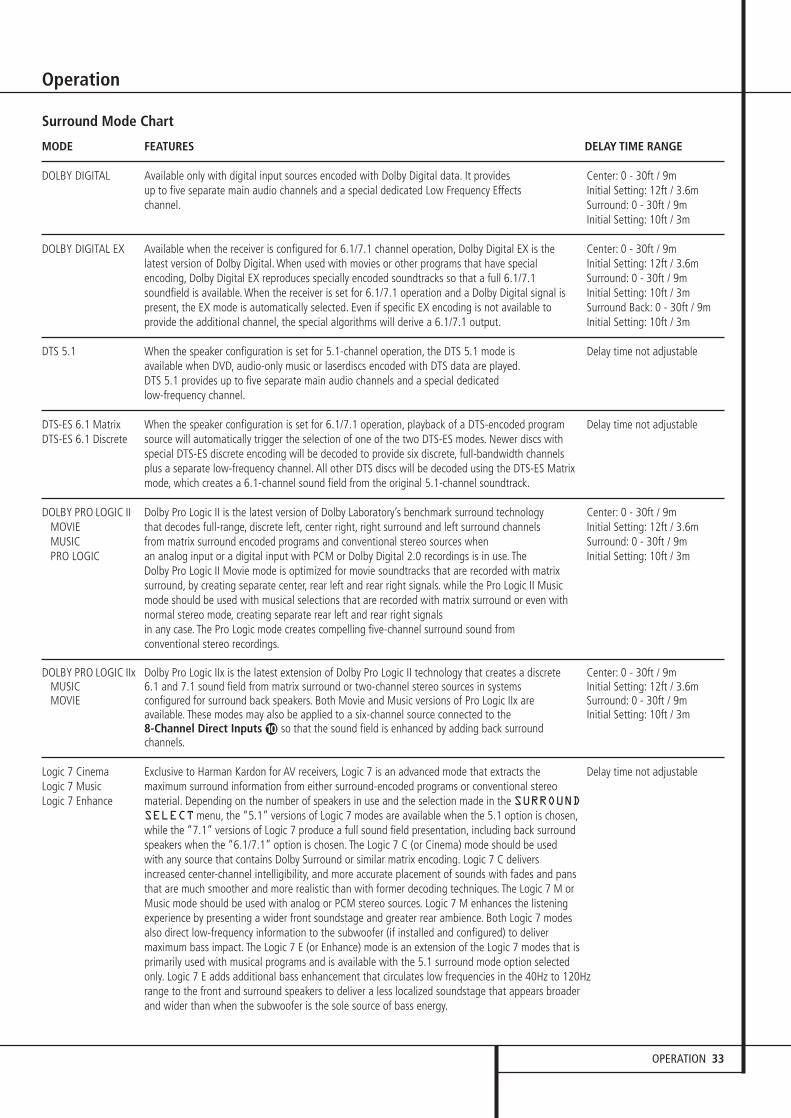
OPERATION 33
Operation
Surround Mode Chart
MODE FEATURES DELAY TIME RANGE
DOLBY DIGITAL Available only with digital input sources encoded with Dolby Digital data. It provides Center: 0 - 30ft / 9mup to five separate main audio channels and a special dedicated Low Frequency Effects Initial Setting: 12ft / 3.6m channel. Surround: 0 - 30ft / 9m
Initial Setting: 10ft / 3m
DOLBY DIGITAL EX Available when the receiver is configured for 6.1/7.1 channel operation, Dolby Digital EX is the Center: 0 - 30ft / 9mlatest version of Dolby Digital. When used with movies or other programs that have special Initial Setting: 12ft / 3.6m encoding, Dolby Digital EX reproduces specially encoded soundtracks so that a full 6.1/7.1 Surround: 0 - 30ft / 9msoundfield is available. When the receiver is set for 6.1/7.1 operation and a Dolby Digital signal is Initial Setting: 10ft / 3mpresent, the EX mode is automatically selected. Even if specific EX encoding is not available to Surround Back: 0 - 30ft / 9mprovide the additional channel, the special algorithms will derive a 6.1/7.1 output. Initial Setting: 10ft / 3m
DTS 5.1 When the speaker configuration is set for 5.1-channel operation, the DTS 5.1 mode is Delay time not adjustableavailable when DVD, audio-only music or laserdiscs encoded with DTS data are played.DTS 5.1 provides up to five separate main audio channels and a special dedicated low-frequency channel.
DTS-ES 6.1 Matrix When the speaker configuration is set for 6.1/7.1 operation, playback of a DTS-encoded program Delay time not adjustableDTS-ES 6.1 Discrete source will automatically trigger the selection of one of the two DTS-ES modes. Newer discs with
special DTS-ES discrete encoding will be decoded to provide six discrete, full-bandwidth channelsplus a separate low-frequency channel. All other DTS discs will be decoded using the DTS-ES Matrix mode, which creates a 6.1-channel sound field from the original 5.1-channel soundtrack.
DOLBY PRO LOGIC II Dolby Pro Logic II is the latest version of Dolby Laboratory’s benchmark surround technology Center: 0 - 30ft / 9mMOVIE that decodes full-range, discrete left, center right, right surround and left surround channels Initial Setting: 12ft / 3.6mMUSIC from matrix surround encoded programs and conventional stereo sources when Surround: 0 - 30ft / 9mPRO LOGIC an analog input or a digital input with PCM or Dolby Digital 2.0 recordings is in use. The Initial Setting: 10ft / 3m
Dolby Pro Logic II Movie mode is optimized for movie soundtracks that are recorded with matrix surround, by creating separate center, rear left and rear right signals. while the Pro Logic II Music mode should be used with musical selections that are recorded with matrix surround or even withnormal stereo mode, creating separate rear left and rear right signals in any case. The Pro Logic mode creates compelling five-channel surround sound from conventional stereo recordings.
DOLBY PRO LOGIC IIx Dolby Pro Logic IIx is the latest extension of Dolby Pro Logic II technology that creates a discrete Center: 0 - 30ft / 9mMUSIC 6.1 and 7.1 sound field from matrix surround or two-channel stereo sources in systems Initial Setting: 12ft / 3.6mMOVIE configured for surround back speakers. Both Movie and Music versions of Pro Logic IIx are Surround: 0 - 30ft / 9m
available. These modes may also be applied to a six-channel source connected to the Initial Setting: 10ft / 3m8-Channel Direct Inputs � so that the sound field is enhanced by adding back surround channels.
Logic 7 Cinema Exclusive to Harman Kardon for AV receivers, Logic 7 is an advanced mode that extracts the Delay time not adjustableLogic 7 Music maximum surround information from either surround-encoded programs or conventional stereo Logic 7 Enhance material. Depending on the number of speakers in use and the selection made in the SURROUND
SELECTmenu, the “5.1” versions of Logic 7 modes are available when the 5.1 option is chosen,while the “7.1” versions of Logic 7 produce a full sound field presentation, including back surround speakers when the “6.1/7.1” option is chosen. The Logic 7 C (or Cinema) mode should be used with any source that contains Dolby Surround or similar matrix encoding. Logic 7 C delivers increased center-channel intelligibility, and more accurate placement of sounds with fades and pans that are much smoother and more realistic than with former decoding techniques. The Logic 7 M or Music mode should be used with analog or PCM stereo sources. Logic 7 M enhances the listening experience by presenting a wider front soundstage and greater rear ambience. Both Logic 7 modes also direct low-frequency information to the subwoofer (if installed and configured) to deliver maximum bass impact. The Logic 7 E (or Enhance) mode is an extension of the Logic 7 modes that is primarily used with musical programs and is available with the 5.1 surround mode option selected only. Logic 7 E adds additional bass enhancement that circulates low frequencies in the 40Hz to 120Hz range to the front and surround speakers to deliver a less localized soundstage that appears broader and wider than when the subwoofer is the sole source of bass energy.

34 OPERATION
Operation
Surround Mode Chart
MODE FEATURES DELAY TIME RANGE
DTS Neo:6 Cinema These two modes are available when any analog source is playing to create a six-channel Delay time not adjustableDTS Neo:6 Music surround presentation from conventional Matrix-encoded and traditional Stereo sources. Select
the Cinema version of Neo:6 when a program with any type of analog Matrix surround encoding is present. Select the Music version of Neo:6 for optimal processing when a nonencoded,two-channel stereo program is being played.
DOLBY 3 STEREO Uses the information contained in a surround-encoded or two-channel stereo program to No surround channelscreate center-channel information. In addition, the information that is normally sent to the rear-channel surround speakers is carefully mixed in with the front-left and front-right channels for increased realism. Use this mode when you have a center-channel speaker but no surround speakers.
THEATER The THEATER mode creates a sound field that resembles the acoustic feeling of a Delay time not adjustablestandard live performance theater, with stereo and even pure mono sources.
HALL 1 The two Hall modes create sound fields that resemble a small (HALL1) or Delay time not adjustableHALL 2 medium sized (HALL 2) concert hall, with stereo and even pure mono sources.
Dolby Virtual Speaker Dolby Virtual Speaker technology uses a next-generation advanced algorithm to reproduce the No surround channelsReference dynamics and surround sound effects of a precisely placed 5.1-channel speaker system using only Wide front left and right speakers. In the Reference Mode, the apparent width of the sound across
the front image is defined by the distance between the two speakers. The Wide Mode provides a wider, more spacious front image when the two speakers areclose together.
5-Channel Stereo This mode takes advantage of multiple speakers to place a stereo signal at both the front and No delay available in7-Channel Stereo back of a room. Depending on whether the AVR has been configured for either 5.1 or 6.1/7.1 these modes
operation, one of these modes, but not both, is available at any time. Ideal for playing music in situations such as a party, this mode places the same signal at the front-left and surround-left,and at the front-right and surround-right speakers. The center channel is fed a summed mono mix of the in-phase material of the left and right channels.
SURROUND This mode turns off all surround processing and presents the pure left- and right- No surround channelsOFF (STEREO) channel presentation of two-channel stereo programs.
Dolby Headphone Dolby Headphone enables ordinary stereo headphones to portray the sound of a five-speaker No surround channelsDH1 surround-playback system. The DH1 mode creates headphone presentation that resembles a small,DH2 well-damped room and is appropriate for use with both movies and music-only recordings.DH3 The DH2 mode creates a more acoustically live room particularly suited to music listening.
The DH3 mode creates a larger room, more like a concert hall or movie theater.
OPERATION 35
Operation
Basic Operation
Once you have completed the setup and configu-ration of the AVR, it is simple to operate andenjoy. The following instructions should be fol-lowed for you to maximize your enjoyment ofyour new receiver:
Turning the AVR On or Off• When using the AVR for the first time, you mustpress the Main Power Switch 1 on the frontpanel to turn the unit on. This places the unit in aStandby mode, as indicated by the amber color ofthe Power Indicator 3. Once the unit is inStandby, you may begin a listening session bypressing the System Power Control 2 or theSource button % on the front panel or theAVR Selector 5∫. Note that the PowerIndicator 3 will turn blue. This will turn the uniton and return it to the input source that was lastused. The unit may also be turned on from Standbyby pressing any of the Source Selector buttonson the remote 4567∫ç∂ or theSource button % on the front panel.
NOTE: After pressing one of the Input Selectorbuttons 4∂ to turn the unit on, press the AVR Selector 5∫ to have the remotecontrol the AVR functions.
To turn the unit off at the end of a listening ses-sion, simply press the System Power Control2 on the front panel or the Power Off Button3å on the remote. Power will be shut off toany equipment plugged into the rear panelSwitched AC Outlets * and the PowerIndicator 3 will turn orange.
When the remote is used to turn the unit “off” itis actually placing the system in a Standby mode,as indicated by the orange color of the PowerIndicator 3.
When you will be away from home for anextended period of time it is always a good ideato completely turn the unit off with the frontpanel Main Power Switch 1.
NOTE: All preset memories may be lost if theunit is left turned off with the Main PowerSwitch 1 for more than two weeks.
Using the Sleep Timer• To program the AVR for automatic turn-off,press the Sleep Button 9 on the remote. Eachpress of the button will increase the time beforeshut down in the following sequence:
The sleep time will be displayed in the LowerDisplay Line ˜ and it will count down untilthe time has elapsed.
When the programmed sleep time has elapsed,the unit will automatically turn off (to Standbymode). Note that the front panel display will dimto one half brightness when the Sleep function isprogrammed. To cancel the Sleep function, pressand hold the Sleep Button 9 until the infor-mation display returns to normal brightness andthe Sleep indicator numbers disappear and thewords SLEEPOFF appear in the MainInformation Display ˜.
Source Selection
• To select a source, press any of the SourceSelector buttons on the remote 467ç∂.
NOTE: After pressing one of the Input Selectorbuttons 4∂ to turn the unit on, press the AVR Selector 5∫ to have the remotecontrol the AVR functions.
• The input source may also be changed bypressing the front-panel Input Source Selectorbutton %. Each press of the button will movethe input selection through the list of availableinputs.
• As the input is changed, the AVR will automati-cally switch to the digital input (if selected), sur-round mode component video input, A/V SyncDelay and Night Mode configurations that werein effect the last time that input was used. If theLEVELTRIM line on the CHANNELADJUSTmenu (Fig. 12) was set to INDE-PENDENT, as shown on page 31, the settingsfor channel output levels will also change to thepreset values.
• The front-panel Video 4 Inputs Ô, OpticalDigital 4 Input * or the Coaxial Digital 4Input Ó may be used to connect a device suchas a video game or camcorder to your homeentertainment system on a temporary basis.
• As the input source is changed, the new inputname will appear momentarily as an on-screendisplay in the lower third of the video display. Theinput name will also appear in the MainInformation Display ˜.
• When a pure audio input (CD, Tuner, Tape, 6/8Channel Input) is selected, the last video inputused remains routed to the Video Outputs � (except from its own Video 1/ source) andVideo Monitor Output �. This permitssimultaneous viewing and listening to differentsources.
• When a Video source is selected, its audiosignal will be fed to the speakers and the videosignal for that input will be routed to the appro-priate Monitor Output Jack � and will be view-able on a TV monitor connected to the AVR. If acomponent video source is connected to the DVD� or Video 1 or 2 �� Component Inputs,it will be routed to the Component Video
Outputs �. Make certain that your TV is set tothe proper input to view the appropriate videosignal (composite, S-Video or component video,see Notes for S-Video on page 16).
6-Channel/8-Channel Direct Input
• There are two input choices available for usewith sources such as a DVD-Audio or SACD play-er that are connected to the 8-Channel DirectInputs �. Select the appropriate input accord-ing to the way your system and source equip-ment is configured:
• The 6 CHDIRECT input should be usedwhen the SBR and SBL inputs are NOT in use andthe input source device has its own internal bassmanagement system. This input passes the inputfrom the source directly through to the volumecontrol without any analog to digital conversionand it mutes the unused input jacks to preventunwanted noise from interfering with system per-formance.
• The 8 CHDIRECTINPUT should beused when an input is connected to all eight 8-Channel Direct Inputs � and when theinput source device has its own internal bassmanagement system. This input passes the inputfrom the source directly through to the volumecontrol without any analog to digital conversion.
Note that when the 6-Channel or 8-ChannelInput is in use, you may not select a surroundmode, as the external decoder determines theprocessing in use. In addition, there is no signalat the record outputs or bass management whenthe 6-Channel or 8-Channel Direct Input is in useand the tone or balance controls will notfunction.
Controls and Use of Headphones
• Adjust the volume to a comfortable level usingthe front panel Volume Control ı or remoteVolume Up/Down )î buttons.
• To temporarily silence all speaker outputs pressthe Mute button ,K. This will interrupt theoutput to all speakers and the headphone jack,but it will not affect any recording or dubbingthat may be in progress. When the system ismuted, the word MUTEwill blink in the MainInformation Display ˜. Press the Mutebutton ,K again to return to normaloperation.
• During a listening session you may wish toadjust the Bass Control and Treble Control tosuit your listening tastes or room acoustics. Notethat these controls (and Balance) will not func-tion when the 6/8 channel direct input is in use.
• To set the output of the AVR so that the outputis “flat,” with the tone and balance controls de-activated, press the Tone Mode button 8-once or twice so that the words ToneOut
90min
80min
70min
60min
50min
40min
30min
20min
10min OFF
36 OPERATION
Operation
appear momentarily in the Main InformationDisplay ˜. To return the tone controls to anactive condition, press the Tone Mode 8 but-ton once or twice so that the words ToneInmomentarily appear in the Main InformationDisplay ˜.
• When the tone controls are active, the amountof bass and treble boost/cut may be adjusted byfirst pressing the Tone Mode Button on thefront panel 8 or the remote - two or threetimes until the desired setting (BASSMODE orTREBLEMODE) appears in the on-screen dis-play and the Lower Display Line ˜. Next, usethe ⁄/¤ Navigation Button E on theremote or the ‹/› Button on the front panel7$ to change the setting as desired. The unitwill return to normal operation within five sec-onds after the setting is changed.
• For private listening, plug the 6.3 mm stereophone plug from a pair of stereo headphones intothe front panel Headphone Jack 4.Note that when the headphone’s plug is connect-ed, the speakers will automatically mute and atwo-channel stereo signal will be sent to theheadphones. The Lower Display Line ˜ willread DOLBYH: BP, indicating that the head-phone output is in the Bypass mode, and to con-firm that no processing is being used.
• When the headphones are in use, you may takeadvantage of the Dolby Headphone modes tobring added spaciousness to headphone listening.Press the Dolby Mode Select Button M orthe Surround Mode Group Selector 5 tocycle through the three Dolby Headphone modesto select the one that you prefer.
Surround Mode Selection
One of the most important features of the AVR is its ability to reproduce a full multichannelsurround sound field from digital sources, analogmatrix surround encoded programs and standardstereo or even mono programs.
Selection of a surround mode is based on personaltaste, as well as the type of program source materi-al being used. For example, CDs, motion pictures orTV programs bearing the logo of one of the majorsurround-encoding processes, such as DolbySurround should be played in either the Dolby ProLogic II Movie (with movies) or Music (with music)surround mode, with any DTS NEO:6 mode orwith Harman Kardon´s exclusive Logic 7 MovieMode, to create a full range 5.1 channel or (withLogic 7 and DTS NEO:6) even 7.1 channel sur-round signal from surround encoded programs,with a stereophonic left and right rear signal, justas it was recorded (e.g. sound being recordedfrom left rear side will be heard from that sideonly, for more details see chart on page 33).
When no rear speakers are in use, the Dolby 3Stereo mode should be selected with all surroundrecordings.
Note that when Dolby Digital 2.0 signals (e.g."D.D. 2.0" tracks from DVD), that are encodedwith Dolby Pro Logic information, are received viaany digital input, the Dolby Pro Logic II Moviemode will be selected automatically (in additionto the Dolby Digital mode) and will decode a fullrange 5.1 channel surround sound even fromthose recordings (see also "Dolby Digital" onpage 36).
To create wide, enveloping sound field environ-ments and defined pans and flyovers with all ana-log stereo recordings select the Dolby Pro Logic IIMusic or Emulation mode or Harman Kardon’sexclusive Logic 7 Music mode for a dramaticimprovement in comparison to the Dolby ProLogic ( I ) mode of former times.
NOTE: Once a program has been encoded withmatrix surround information, it retains the surroundinformation as long as the program is broadcast instereo. Thus, movies with surround sound may bedecoded via any of the analog surround modessuch as Pro Logic II Cinema, Logic 7 Cinema or DTSNeo:6 Cinema, when they are broadcast via con-ventional TV stations, cable,pay-TV and satellite transmission. In addition, agrowing number of made-for-television programs,sports broadcasts, radio dramas and music CDs arealso recorded in surround sound. You may view alist of these programs at the Dolby LaboratoriesWeb site at www.dolby.com.
Even when a program is not listed as carryingintentional surround information, you may find thatthe Dolby Pro Logic II, Dolby Pro Logic IIx,DTS NEO:6 Music or Logic 7 Music or Enhancedmodes often deliver enveloping surround presenta-tions through the use of the natural surround infor-mation present in all stereo recordings.
However, for stereo programs without any surroundinformation the Theater, Hall and 5/7CH Stereomodes should be tried (effective particularly withold ”extreme” stereo recordings) and for monoprograms, we suggest that you try the Theater orHall modes.
Surround modes are selected using either thefront panel controls or the remote. To select a newsurround mode from the front panel, first pressthe Surround Mode Group Selector Button5 until the desired major surround mode groupsuch as Dolby, DTS or Logic 7 is selected. Next,press the Surround Mode Selector Button 9to choose the specific individual surround mode.
To select a surround mode using the remote con-trol, press the button for the major surroundmode group that includes the mode you wish tochoose from: Dolby M, DTS Surround N,DTS Neo:6 �, Logic 7 O, Stereo � orDSP Surround A. The first press of the buttonwill show the current mode from that group if it isalready in use, or the first available mode if youare currently using another mode. To cycle
through the available modes in that group pressthe button again until the desired mode appearsin the Lower Display Line ˜ and the on-screen display.
To select from the DSP modes (Hall 1, Hall 2,Theater) press the Surround Mode SelectorA repeatedly to scroll through the list of avail-able modes.
Note that the Dolby Digital or DTS modes mayonly be selected when a digital input is in use. Inaddition, when a digital source is present, the AVRwill automatically select and switch to the correctmode (Dolby Digital or DTS), regardless of themode that has been previously selected. For moreinformation on selecting digital sources, see the fol-lowing section of this manual.
When the 6-Channel/8-Channel direct inputs arein use there is no surround processing, as theseinputs take the analog output signals from anoptional, external DVD-Audio or SACD player, oranother source device and carry them straightthrough to the volume control.
To listen to a program in traditional two-channelstereo, using the front left and front right speakers only (plus the subwoofer, if installed andconfigured), press the Stereo Button 5�until SURROFF appears in the MainInformation Display ˜.
Digital Audio Playback
Digital audio is a major advancement over olderanalog surround processing systems such asDolby Pro Logic. It delivers five or six discretechannels: left front, center, right front, leftsurround and right surround and with DTS ES (seebelow) even surround back (with identical signalsfor left and right). Each channel reproduces fullfrequency range (20Hz to 20kHz) and offersdramatically improved dynamic range andsignificant improvements to signal-to-noise ratios.In addition, digital systems have the capability todeliver an additional channel that is specificallydevoted to low-frequency information. This is the“.1” channel referred to when you see thesesystems described as “5.1,” “6.1” or “7.1”. Thebass channel is separate from the other channels,but since it is intentionally bandwidth-limited,sound designers have given it that uniquedesignation.
Dolby Digital Dolby Digital (originally known as AC-3®) is astandard part of DVD, and is available on speciallyencoded LD discs and satellite broadcasts and it isa part of the new high-definition television(HDTV) system.
Note that an optional, external RF demodulator isrequired to use the AVR to listen to the DolbyDigital sound tracks available on laser discs.Connect the RF output of the LD player to thedemodulator and then connect the digital output

OPERATION 37
Operation
of the demodulator to the Optical or Coaxialinputs �*Ó of the AVR. No demodulatoris required for use with DVD players or DTS-encoded laser discs.
In order to provide maximum playback compati-bility with DVDs, the AVR 435 receiver will alwaysdefault first to the playback mode embedded in adisc’s digital “flag” information. For Dolby Digitaldiscs, the following playback modes are initiallyselected after the AVR locks to the incoming digi-tal audio data stream to identify the selected:
• When a 5.1 audio stream is detected, the DolbyDigital 5.1 format will be selected, regardlessof the number of speakers in your system, incompliance with Dolby Laboratories licensingrequirements.
• When a disc with the Dolby Digital EX formatflag is played, your system will automaticallyswitch to the EX mode when seven main chan-nel speakers are available.
• When a disc with Dolby Digital data, but only2.0 audio is detected, the default mode isDolby Digital with Pro Logic II post-processingwhen you have a 5.1 speaker system, or DolbyDigital with Pro Logic IIx post-processing whenyou have a 7.1 speaker system.
• Depending on the number of speaker channelsavailable in your system, once the AVR locks tothe digital signal, you may select any surroundmode or post-processing option that is avail-able, based on the incoming data stream’s pos-sible restrictions and the number of speakers inyour system. For example, when a 5.1 or 2.0audio stream is in use, you may select alternatepostprocessing such as Logic 7/7-ChannelMovie Mode post-processing to create the rearsurrounds in 7.1 speaker systems.
DTSDTS is another digital audio system that is capa-ble of delivering 5.1, 6.1 or 7.1 audio. Althoughboth DTS and Dolby Digital are digital, they usedifferent methods of encoding the signals, andthus they require different decoding circuits toconvert the digital signals back to analog.
DTS-encoded sound tracks are available on selectDVD and LD discs, as well as on special audio-only DTS CDs. You may use any LD, DVD or CDplayer equipped with a digital output to playDTS-encoded special audio-only CDs with theAVR, but DTS-LDs can be played on LD playersand DTS-DVDs on DVD players only. All that isrequired is to connect the player’s digital outputto either the Optical or Coaxial input on therear panel � or front panel *Ó.
In order to listen to DVDs encoded with DTSsound tracks, the DVD player must be compatiblewith the DTS signal as indicated by a DTS logo onthe player’s front panel. Note that early DVDplayers may not be able to play DTS- encodedDVDs. This does not indicate a problem with theAVR, as some players cannot pass the DTS signalthrough to the digital outputs. If you are in doubtas to the capability of your DVD player to handleDTS DVDs, consult the player’s owner’s manual.
Please note that some DVD players are shippedwith their output set for Dolby Digital only. Toinsure that DTS data is being sent to the AVR,please check the setup menu system on yourDVD player to make certain that DTS data outputis enabled.
PCM Audio PlaybackPCM (Pulse Code Modulation) is the non- com-pressed digital audio system used for compactdiscs, Non-Dolby Digital/DTS Laserdiscs and somespecial PCM encoded DVDs. The digital circuits inthe AVR are capable of high quality digital-to-ana-log decoding, and they may be connected directlyto the digital audio output of your CD/DVD or LDplayer (LD only for PCM or DTS programs, forDolby Digital laser discs an RF adapter is needed,see ”Dolby Digital” above).
Connections may be made to either the Opticalor Coaxial inputs � on the rear panel or thefront panel Digital Inputs *Ó.
To listen to a PCM digital source, first select theinput for the desired source (e.g., CD) to feed itsvideo signal (if any) to the TV monitor and to pro-vide its analog audio signal for recording. Nextpress the Digital Select button ÛG and thenuse the ⁄ /¤ buttons E on the remote, or theSelector buttons7$ on the front panel, untilthe desired choice appears in the Lower DisplayLine ˜, then press the Set button @F toconfirm the choice.
In most cases this will be 48KHZ, though inthe case of specially mastered, high-resolutionaudio discs you will see a 96KHZ indication.
The PCM48KHZ indication will also appearwhen modes or inputs are changed for analogsources. In those cases the system is telling youthe sampling frequency used internally at theoutput of the analog-to-digital converters thatchange the incoming signal from a VCR, tapedeck, the tuner, or other ana-log source to digital.
During PCM playback the unit automatically willturn to the default surround mode or to theLOGIC7 mode but you also may select anysurround mode except Dolby Digital or DTS.
MP3 Audio PlaybackThe AVR is one of the few A/V receivers to pro-vide on-board decoding for the MP3 audio for-mat used on specific computer audio files and byportable MP3 players/recorders. In addition, somenew CD and DVD players are capable of playingback optical discs that are recorded with MP3,rather than standard CD audio information. Byoffering MP3 decoding, the AVR is able to delivermore precise conversion of the digital signals toan analog output, along with the benefits of listening to MP3 audio through theAVR’s high current amplifier and the speakersfrom your surround system, rather than the small-er speakers and low powered amplifiers typicallyused with computers.To take advantage of the AVR’s MP3 capabilities,simply connect the digital (SPDIF) output of acomputer sound card able to feed the MP3 for-mat to its digital output, or the digital (SPDIF)output of MP3 compatible CD or DVD players orof a portable MP3 player with a digital output toeither the rear panel Digital Inputs � orthe front panel Digital Inputs *Ó.
NOTES:• The AVR is only capable of playing signals inthe MP3 (MPEG 1/Layer 3) format. It is not com-patible with other computer audio codecs.
• The MP 3 DSP mode found in the new AVRrequires an MP3 SPDIF stream. Presently, only afew units provide this but in the coming genera-tions of motherboards and operating systemupdates this will follow, since SPDIF is the stan-dard for audio & video hardware.
• The digital audio input signal may be eitheroptical or coaxial, but the signal must be in theMP3 SPDIF format. Direct connection of USB orserial data outputs is not possible, even thoughthe signals are in the MP3 format. If you haveany questions about the data output format fromyour computer or a sound card, check with thedevice’s Owner’s Manual or contact the manufac-turer’s technical support area.
• If your computer or sound card’s digital outputis not capable of direct connection to the AVR orif the output is not capable of delivering MP3data stream, you may use an optional, externaltranscoder, such as those available from HarmanKardon to convert the USB output of a computerto a format compatible with the AVR. Contactyour Harman Kardon dealer for additional details.

38 OPERATION
Operation
Selecting a Digital SourceTo utilize either digital mode you must have properly connected a digital source to the AVR.Connect the digital outputs from DVD players,HDTV receivers, satellite systems or CD players tothe Optical or Coaxial inputs on the rear orfront panel �*Ó. In order to provide abackup signal and a source for analog stereorecording, the analog outputs provided on digitalsource equipment should also be connected totheir appropriate inputs on the AVR rear panel(e.g., connect the analog stereo audio outputfrom a DVD to the DVD Audio inputs � on therear panel when you connect the source’s digitaloutputs).
To select a digital source such as DVD, first selectits input using the remote or front panel InputSelector 4% as outlined in this manual inorder to feed its video signal (if any) to the TVmonitor and to provide its analog audio signal forrecording. When the digital input associated withthe input selected (e.g. “DVD”) is not selectedautomatically (due to the input settings made ear-lier during the system configuration, see page 21),select the digital source by pressing the DigitalInput Selector button GÛ and then usingthe ⁄/¤ buttons E on the remote or theSelector buttons7$ on the front panel tochoose any of the OPTICAL or COAXIALinputs, as they appear in the Upper DisplayLine ˜ or on-screen display.
When the digital source is playing, the AVR willautomatically detect whether it is a multichannelDolby Digital or DTS source or a MP3 or conven-tional PCM signal, which is the standard outputfrom CD players.
Note that a digital input (e.g. coaxial) remainsassociated with any analog input (e.g. DVD) assoon as it is selected, thus the digital input neednot be re-selected each time the appropriateinput choice (e.g. DVD) is made.
Digital Bitstream IndicatorsWhen a digital source is playing, the AVR sensesthe type of bitstream data that is present. Usingthis information, the correct surround mode willautomatically be selected. For example, DTS bit-streams will cause the unit to switch to DTSdecoding, and Dolby Digital bitstreams will enableDolby Digital decoding. When the unit senses PCMdata, from CDs and LDs and some music DVDs orcertain tracks on normal DVDs, it will allow theappropriate surround mode to be selected manu-ally. Since the range of available surround modesdepends on the type of digital data that is present,the AVR uses a variety of indicators to let youknow what type of signal is present. This will helpyou to understand the choice of modes and theinput channels recorded on the disc.
When a digital source is playing, the AVR willdisplay a variety of messages to indicate the typeof bitstream received. These messages will appearshortly after an input or surround mode ischanged, and will remain in the Main Infor-
mation Display ˜ for about five secondsbefore the display returns to the normal surroundmode indication.
For Dolby Digital and DTS sources, a three digitindication will appear, showing the number ofchannels present in the data. An example of thistype of display is 3/2/.1.
The first number indicates how many discretefront channel signals are present.
• A 3 tells you that separate front left, center andfront right signals are available. This will be dis-played for Dolby Digital 5.1 and DTS 5.1 pro-grams.
• A 2 tells you that separate front left and rightsignals are available, but there is no discretecenter channel signal. This will be displayed forDolby Digital bit streams that have stereo pro-gram material.
• A 1 tells you that there is only a mono channelavailable in the Dolby Digital bitstream.
The middle number indicates how many discretesurround channel signals are present.
• A "3" tells you that separate, discrete left sur-round, center surround and right surround sig-nals are present. This is available only on discswith DTS-ES digital audio.
• A 2 tells you that separate surround left andright signals are available. This will be displayedfor Dolby Digital 5.1 and DTS 5.1 programs.
• A 1 tells you that there is only a single, sur-round encoded surround channel. This willappear for Dolby Digital bit streams that havematrix encoding.
• A 0 indicates that there is no surround channelinformation. This will be displayed for two-chan-nel stereo programs.
The last number indicates if there is a discreteLow Frequency Effects (LFE) channel. This is the“.1” in the common abbreviation of “5.1” soundand it is a special channel that contains only bassfrequencies.
• A .1 tells you that an LFE channel is present.This will be displayed for Dolby Digital 5.1 andDTS 5.1 programs, as available.
• A 0 indicates that there is no LFE channel infor-mation available. However, even when there isno dedicated LFE channel, low frequency soundwill be present at the subwoofer output whenthe speaker configuration is set to show thepresence of subwoofer.
• The information in the right side of the displaywill tell you if the digital audio data contains aspecial flag signal that will automatically acti-vate the appropriate 6.1 or 7.1 mode. This willbe shown as EX-ON or EX-OFF for Dolby Digitalbitstreams and ES-ON or ES-OFF for DTS bit-streams.
When Dolby Digital 3/2/.1 or DTS 3/2/.1 signalsare being played, the AVR will automaticallyswitch to the proper surround mode, and no otherprocessing may be selected. When a Dolby Digitalsignal with a 3/1/0 or 2/0/0 signal is detected youmay select any of the Dolby surround modes.
It is always a good idea to check the readout forthe channel data to make certain that it matchesthe audio logo information shown on the back ofa DVD package. In some cases you will see indica-tion for “2/0/0” even when the disc contains afull 5.1, or 3/2/.1 signal. When this happens,check the audio output settings for your DVDplayer or the audio menu selections for the specif-ic disc being played to make certain that the play-er is sending the correct signal to the AVR.
Speaker/Channel IndicatorsIn addition to the Bitstream Indicators, the AVR features a set of unique channel-input indi-cators that tell you how many channels of digitalinformation are being received and/or whetherthe digital signal is interrupted.
These indicators are the L/C/R/LFE/SL/SR/SBL/SBRletters that are inside the center boxes of theSpeaker/Channel Input Indicators Ú in thefront panel Main Information Display ˜.When a standard analog stereo or matrix surround signal is in use, only the “L” and “R”

OPERATION 39
Operation
indicators will light, as analog signals have onlyleft and right channels.
Digital signals, however, may have one, two, five,six or seven separate channels, depending on theprogram material, the method of transmissionand the way in which it was encoded. When adigital signal is playing, the letters in these indicators will light in response to the specificsignal being received. It is important to note thatalthough Dolby Digital, for example, is referred toas a “5.1” system, not all Dolby Digital DVDs oraudio tracks selected on DVD or other DolbyDigital programs are encoded for 5.1. Thus, it issometimes normal for a DVD with a Dolby Digitalsoundtrack to trigger only the “L” and “R”indicators.
NOTE: Many DVD discs are recorded with both“5.1” and “2.0” versions of the same sound-track. When playing a DVD, always be certain tocheck the type of material on the disc. Most discsshow this information in the form of a listing oricon on the back of the disc jacket. When a discdoes offer multiple soundtrack choices, you mayhave to make some adjustments to your DVDplayer (usually with the “Audio Select” button orin a menu screen on the disc) to send a full 5.1feed to the AVR or to select the appropriateaudio track and thus language. It is also possiblefor the type of signal feed to change during thecourse of a DVD playback. In some cases the pre-views of special material will only be recorded in2.0 audio, while the main feature is available in5.1 audio. As long as your DVD player is set for6-channel output, the AVR will automaticallysense changes to the bitstream and channelcount and reflect them in these indicators.
Important Note: When a digital surroundsource (Dolby Digital, DTS) is played, the lettersSBL/SBR for the Surround Back channels willappear only when a DTS ES DISCRETE 6.1 sourceis played. Then this surround mode will beindicated in the front display and on-screendisplay. With all other recordings the icons for thesurround back speakers may light (when thosespeakers have been configured) to indicate that asignal will be fed to them (Matrix decoded withNEO:6, LOGIC 7 or 7 CH Stereo), but no lettersinside will light as the unit will not receive aninput signal for the surround back channels.
The letters used by the Speaker/Channel InputIndicators Ú also flash to indicate when a bit-stream has been interrupted. This will happenwhen a digital input source is selected before theplayback starts, or when a digital source such asa DVD is put into a Pause mode. The flashingindicators remind you that the playback hasstopped due to the absence of a digital signaland not through any fault of the AVR. This is nor-mal, and the digital playback will resume oncethe playback is started again.
Night Mode A special feature of Dolby Digital is the Nightmode, which enables Dolby Digital input sourcesto be played back with full digital intelligibiltywhile reducing the maximum peak level and lift-ing the low levels by 1/4 to 1/3. This preventsabruptly loud transitions from disturbing otherswithout reducing the impact of the digital source.The Night mode is available only when the DolbyDigital mode is selected.
The Night mode may be engaged when a DolbyDigital DVD is playing by pressing the NightButton B on the remote. Next, press the ⁄/¤buttons E to select either the middle range orfull compression versions of the Night mode. Toturn the Night mode off, press the ⁄/¤ buttonsE until the message in the lower third of thevideo display and the Lower Display Line ˜reads D-RANGEOFF.
The Night mode may also be selected to alwaysbe on as soon as the Dolby Digital mode is activated at either level of compression using theoptions in the SurroundSelectmenu.See page 23 for information on using the menusto set this option.
IMPORTANT NOTES ON DIGITAL PLAYBACK:• When the digital playback source is stopped, orin a pause, fast forward or chapter search mode,the digital audio data will momentarily stop, andthe channel position letters inside the Speaker/Channel Indicators Ú will flash. This is nor-mal and does not indicate a problem with eitherthe AVR or the source machine. The AVR willreturn to digital playback as soon as the data isavailable and when the machine is in a standardplay mode.
• Although the AVR will decode virtually all DVDmovies, CDs and HDTV sources, it is possible thatsome future digital sources may not be compatiblewith the AVR.
• Note that not all digitally encoded programsand not all audio tracks on a DVD contain full5.1 or 6.1 channel audio. Consult the programguide that accompanies the DVD or laser disc todetermine which type of audio has been record-ed on the disc. The AVR will automatically sensethe type of digital surround encoding used, indi-cate it in the Channel Input Indicators Úand adjust to accommodate it.
• When a Dolby Digital or DTS source is playing,you normally may not be able to select some ofthe analog surround modes such as Dolby ProLogic II, Dolby 3 Stereo, Hall, Theater, 5CH/7CHStereo or Logic 7, except with specific DolbyDigital 2.0 recordings that can be played withthe Pro Logic II modes too (see page 34).
• When a digital source is playing, it is possibleto make an analog recording using the Tape �or Video 1 or Video 2 or �� record outputs,even if the source is connected to any digitalinput of the AVR only, as long as "Surround Off"mode is selected (possible with a PCM sourceonly). But the analog two channel signal, even ofa Dolby Digital (not DTS) source, the ”Downmix”to Stereo or Dolby Surround, can be recorded byconnecting its analog audio outputs to theappropriate analog inputs (e.g. DVD) of the AVR.Additionally, the digital signals will be passedthrough to the Digital Audio Outputs .
Tape RecordingIn normal operation, the audio or video sourceselected for listening through the AVR is sent tothe record outputs. This means that any programyou are watching or listening to may be recordedsimply by placing machines connected to the out-puts for Tape Outputs � or Video 1 or 2Outputs ��� in the record mode.
When a digital audio recorder is connected toany of the Digital Audio Outputs , you areable to record the digital signal using a CD-R,MiniDisc or other digital recording system.Note that all digital signals will be passedthrough to both, coaxial and optical, digital outputs simultanously, no matter which kind ofdigital input was selected.

40 OPERATION
Operation
Output Level Adjustment With Source Signals
Normal output level adjustment for the AVR is established using the test tone, as out-lined on page 26. In some cases, however, it maybe desirable to adjust the output levels using pro-gram material such as a test disc, or a selectionyou are familiar with. Additionally, the outputlevel for the subwoofer and those for the Stereomodes can only be adjusted using this procedure.Note that all adjustments made with any inputwill be effective with all inputs selected, just as itis the case with the adjustment using the testtone.
To adjust the output levels using program materi-al, first select the surround mode for which youwant to trim the speakers (see NOTE below), startyour program material source and set the reference volume for the front left and front rightchannels using the Volume Control )î.
Once the reference level has been set, press theChannel Select button CÙ and note thatFRONT L LEVELwill appear in the LowerDisplay Line ˜. To change the level, first pressthe Set button F@, and then use theSelector buttons 7$ or the ⁄/¤ buttonsE to raise or lower the level. DO NOT use thevolume control, as this will alter the referencesetting.
Once the change has been made, press the Setbutton F@ and then press the Selector but-tons 7$ or the ⁄/¤ buttons E to selectthe next output channel location that you wish toadjust. To adjust the subwoofer level, press theSelector buttons 7$ or the ⁄/¤ buttonsE until WOOFERLEVEL appears in theMain Information Display ˜ or on-screen dis-play (only available if the subwoofer is turnedon).
Press the Set button F@ when the name ofthe desired channel appears in the MainInformation Display ˜ and on-screen display, and follow the instructions shown aboveto adjust the level.
Repeat the procedure as needed until all chan-nels requiring adjustment have been set. Whenall adjustments have been made and no furtheradjustments are made for five seconds, the AVR will return to normal operation.
The channel output may also be adjusted usingthe full-OSD on-screen menu system. First, set thevolume to a comfortable listening level using theVolume Control ı)î. Then, press theOSD button L to bring up the MASTERMENU (Figure 1). Press the ¤ Button E fourtimes until the on-screen › cursor is next to the MANUALSETUP line. Press the SetButton F, select the CHANNELADJUSTline and press the Set Button F to activate theCHANNELADJUSTmenu (Figure 12).
Figure 12
When the menu appears, the internal test tonewill be turned off. This will allow you to use yourexternal test disc or other source material as thetest signal. Then, use the ⁄/¤ Buttons E toselect the channels to be adjusted. At each channel position use the ‹ /› Buttons E tochange the output level.Remember, when you are using a disc with testsignal (e.g. pink noise) or an external signalgenerator as the source, the goal is to have theoutput level at each channel be equal whenheard at the listening position, with any surroundmode selected. When your test source is a normaldisc with music signals, you may adjust the levelfor each channel and surround mode as you pre-fer, e.g. you may lower the center channel levelwhen you find it to be too high or increase thelevel of the rears when you find it to be too lowwith specific surround modes.
If you wish to reset all the levels to their originalfactory default of 0dB offset, press the ⁄/¤
Buttons E so that the on-screen cursor is nextto the LEVELRESET line and press the ‹ /›Buttons E so that the word ON is highlight-ed. After the levels are reset, resume the proce-dure outlined above to reset the levels to thedesired settings. When all adjustments are done,press the ⁄/¤ Buttons E to move the on-screen › cursor so that it is next to BACKTOMANUALSETUP and then press the SetButton F if you wish to go back to the mainmenu to make other adjustments. If you have noother adjustments to make, press the OSDButton L to exit the menu system.
NOTE: The output levels may be separatelytrimmed for each digital and analog surround mode.If you wish to have different trim levels for a specificmode, select that mode and then follow the instruc-tions in the steps shown above.
With Stereo modes the adjustment proceduredescribed above is the only way to trim the out-put level, e.g. to match the Stereo level withother modes.
Dim FunctionSince the AVR will often be used when movies orother video programming is viewed under low-light conditions, you may wish to lower the bright-ness of the front-panel displays and indicators sothat they do not distract from the video presenta-tion. You may dim the displays using the menusystem, as shown on page 41, or you may controlthe brightness directly from the remote.
Simply press the Dim Button D once to dimthe front panel to half the normal brightness level;press it again to turn the displays off. Note thatwhen the displays are dimmed or turned off, theblue lighting around the Standby/On Switch 3will continue to stay lit as a reminder that the AVRis still turned on.
The accent lighting for the Volume Control ıwill remain at its normal level, rather than dimwhen the panel displays are at half brightness.
Note that all changes to the front-panel bright-ness level are temporary; the displays will returnto full brightness after the AVR is turned off andthen on again. To return the displays to full bright-ness without turning the unit off, press the DimButton D as needed until the displays are on.
In addition to lowering the brightness of the dis-plays or turning them off completely, you maywish to have them appear whenever a button onthe remote or front panel is pushed, and thengradually fade out after a set time period. Youmay do this by making the appropriate settings inthe VFDFADETIMEOUT line of theADVANCEDSELECTmenu, as shown onpage 41.
Memory Backup
This product is equipped with a memory backupsystem that preserves tuner presets and systemconfiguration information if the unit is turned offcompletely, accidentally unplugged or subjectedto a power outage. This memory will last forapproximately two weeks, after which time allinformation must be reentered.
* CHANNEL ADJUST *
→ FL : 0 dB SBR: 0 dB
CEN: 0 dB SBL: 0 dB
FR : 0 dB SL : 0 dB
SR : 0 dB SUB: 0 dB
TEST TONE : AUTO OFF MAN
LEVEL RESET: OFF ON
LEVEL TRIM: GLOBAL
EZSET SETTINGS: OFF ON
BACK TO MANUAL SETUP

ADVANCED FEATURES 41
Advanced Features
The AVR is equipped with a number of advancedfeatures that add extra flexibility to the unit’soperation. While it is not necessary to use thesefeatures to operate the unit, they provide addi-tional options that you may wish to use.
Front-Panel-Display Fade
In normal operation, the front-panel displays andindicators remain on at full brightness, althoughyou may also dim them or turn them off as shownon page 40. As an additional option, you may alsoset the AVR so that the displays are on whenevera button is pressed on the front panel or remote,but then fade out after a set period of time.
To set the front-panel displays to the Fade mode,press the OSD Button L to bring the MasterMenu to the screen. Press the ⁄/¤ NavigationButton E so that the � cursor is pointed tothe ADVANCED line, and press the SetButton F to enter the ADVANCEDSELECTmenu (Figure 13).
Figure 13
With the ADVANCEDSELECTmenu onyour video display, press the ⁄/¤ NavigationButton E so that the � cursor is pointed tothe VFDFADETIMEOUT line. Next, pressthe ‹ /› Navigation Button E so that theamount of time that you wish the displays to fadeout after a button is pressed is shown.
Once this time is set and the unit returned to nor-mal operation, the displays will remain on for thetime period selected whenever a button is pressedon the front panel or remote. After that time theywill gradually fade out, with the exception of thelighting surrounding the Standby/On Switch3, which remains on to remind you that the AVRis turned on. Note that if the displays have beenturned completely off using the Dim Button, asshown on page 40, the Fade function will notoperate.
If you wish to make adjustments to other items onthe ADVANCEDSELECTmenu, press the⁄/¤ Navigation Button E to place the �cursor next to the desired item, or place the �cursor next to the BACKTOMASTERMENU line and press the Set Button F tomake an adjustment to another menu. If you havecompleted all adjustments, press the OSDButton L to exit the menu system.
Display Brightness
The AVR’s front panel Main InformationDisplay ˜ is set at a default brightness levelthat is sufficient for viewing in a normally litroom. However, in some home theater installa-tions, you may wish to occasionally lower thebrightness of the display, or turn it off completely.
To change the display brightness setting for a spe-cific listening session, you will need to make anadjustment in the ADVANCEDSELECTmenu. To start the adjustment, press the OSDbutton L to bring the MASTERMENU tothe screen. Press the ⁄ Button E, until the on-screen › cursor is next to the ADVANCED line.Press the Set Button F to enter theADVANCEDSELECTmenu (Figure 13).
To change the brightness setting, at theADVANCEDSELECTmenu, make certainthat the on-screen › cursor is next to the VFDline, and press the › Button E until the desiredbrightness level is highlighted in the video display.When FULL is highlighted, the display is at itsnormal brightness. When HALF is highlighted,the display is at half the normal brightness level.When OFF is highlighted, all of the indicators inthe Main Information Display ˜ will go dark.Note, however, that the Power Indicator 3,will always remain lit to remind you that the unitis turned on.
If you wish to make other adjustments in themenu, press the ⁄/¤ Buttons E until the on-screen › cursor is next to the desired setting orthe BACKTOMASTERMENU line andpress the Set button F. If you have no otheradjustments to make, press the OSD Button Lto exit the menu system.
The display brightness may also be changed bypressing and holding the Set button @ on thefront for three seconds until the message in theMain Information Display ˜ reads VFDFULL. Within five seconds, press the front panelSelector buttons 7$ until the desired bright-ness display level is shown. At that point, pressthe Set button @ again to enter the setting.
Once the desired brightness level is selected, itwill remain in effect until it is changed again oruntil the unit is turned off.
Turn On Volume Level
As is the case with most audio/video receivers,when the AVR is turned on, it will always return tothe volume setting in effect when the unit wasturned off. However, you may prefer to alwayshave the AVR turn on at a specific setting, regard-less of what was last in use when the unit wasturned off. To change the default condition so thatthe same volume level is always used at turn-on,you will need to make an adjustment in theADVANCEDSELECTmenu. To start the
adjustment, press the OSD button L to bringthe MASTERMENU (Figure 1) to the screen.Press the ⁄ button E, until the on-screen ›cursor is next to the ADVANCED line. Press theSet button F to enter the ADVANCEDSELECTmenu (Figure 13).
At the ADVANCEDSELECTmenu makecertain that the on-screen › cursor is next to theVOLUMEDEFAULT line by pressing the⁄/¤ buttons E as needed. Next, press the ›button E so that the word ON is highlighted inthe video display. Next, press the ¤ button Eonce so that the on-screen › cursor is next to theDEFAULTVOLSET line. To set the desiredturn-on volume, press the ‹ /› buttons E orhold them pressed until the desired volume levelis shown on the DEFAULTVOLSET line.Note that this setting may NOT be made with theregular volume controls.
NOTE: Since the setting for the turn-on volumecannot be heard while the setting is being made,you may wish to determine the setting beforemaking the adjustment. To do this, listen to anysource and adjust the volume to the desired levelusing the regular volume controls )î. Whenthe desired volume level to be used at turn-on isreached, make a note of the setting as it appearsin the lower third of the video screen or in theMain Information Display ˜.A typical volume level will appear as a negativenumber such as -25dB. When making the adjustment, use the ‹/› buttons E to enterthis setting.
Unlike some of the other adjustments in thismenu, the turn-on volume default will remain ineffect even when the unit is turned off completely,unless it is changed or turned off in this menu.
If you wish to make other adjustments in themenu, press the ⁄/¤ Buttons E until the on-screen › cursor is next to the desired setting orthe BACKTOMASTERMENU line andpress the Set button F. If you have no otheradjustments to make, press the OSD Button Lto exit the menu system.
Semi-OSD Settings
The semi-OSD system places one line messages atthe lower third of the video display screen when-ever the Volume, Input Source, Surround mode ortuner frequency of any of the configuration set-tings are changed. The semi-OSD system is helpfulin that enables you to have feedback on any con-trol changes or remote commands using the videodisplay when it is difficult to view the front-paneldisplays. However, you may occasionally prefer toturn these displays off for a particular listeningsession. You may also want to adjust the length oftime the displays remain on the screen. Both ofthose options are possible with the AVR.
* A D V A N C E D S E L E C T *
→ VFD FADE TIME OUT: OFF
VFD :FULL HALF OFF
VOLUME DEFAULT : OFF ON
SEMI OSD TIME OUT: 5S
FULL OSD TIME OUT:20S
AUTO POLL :OFF ON
BACK TO MASTER MENU

42 ADVANCED FEATURES / MULTIROOM OPERATION
Advanced Features / Multiroom Operation
To turn off the semi-OSD system, you will need tomake an adjustment in the ADVANCEDSELECTmenu (Figure 13). To start the adjust-ment, press the OSD button L to bring theMASTERMENU to the screen. Press the ⁄Button E, until the on-screen › cursor is next tothe ADVANCED line. Press the Set Button Fto enter the ADVANCEDSELECTmenu.
At the ADVANCEDSELECTmenu makecertain that the on-screen › cursor is next to theSEMIOSD line by pressing the ⁄/¤ buttonsE as needed. Next, press the › button E sothat the word OFF is highlighted in the videodisplay.
Note that this setting is temporary and will re-main active only until it is changed or until theAVR is turned off. Once the unit is turned off, thesemi-OSD displays will remain activated, even ifthey were switched off for the previous listeningsession.
To change the length of time that the semi-OSDdisplays remain on the screen, go to theADVANCEDSELECTMenu as outlined ear-lier, and press the ⁄/¤ buttons E as needed,until the on-screen › cursor is next to theSEMI-OSDTIMEOUT line. Next, press the‹/› Buttons E until the desired time in sec-onds is displayed. Note that unlike most of theother options in this menu, this is a permanentsetting change, and the time-out entry will remainin effect until it is changed, even when the unit isturned off.
If you wish to make other adjustments in themenu, press the ⁄/¤ Buttons E until the on-screen › cursor is next to the desired setting orthe BACKTOMASTERMENU line andpress the Set button F. If you have no otheradjustments to make, press the OSD Button Lto exit the menu system.
Full-OSD Time Out AdjustmentThe FULLOSDmenu system is used tosimplify the setup and adjustment of the AVRusing a series of on-screen menus. The factorydefault setting for these menus leaves them onthe screen for 20 seconds after a period of inac-tivity before they disappear from the screen orTime Out. This Time Out is a safety measure toprevent the menu text from burning into the CRTsin your monitor or projector, which might happenif they were left on indefinitely. However, someviewers may prefer a slightly longer or shorterperiod before the Time Out display.
To change the Full-OSD Time Out, you will needto make an adjustment in the ADVANCEDSELECTmenu (Figure 13). To start the adjust-ment, press the OSD button L to bring theMASTERMENU to the screen. Press the ⁄button E, until the on-screen ¤ cursor is nextto the ADVANCED line. Press the Set ButtonF to enter the ADVANCEDSELECTmenu (Figure 13).
At the ADVANCEDSELECTmenu makecertain that the on-screen › cursor is next to theFULLOSDTIMEOUT line by pressing the⁄/¤ Buttons E as needed. Next, press the‹ /› buttons E until the desired time is dis-played in seconds. Note that unlike most of theother options in this menu, this is a permanentsetting change, and the time-out entry will remainin effect until it is changed, even when the unit isturned off.
If you wish to make other adjustments in themenu, press the ⁄/¤ Buttons E until the on-screen › cursor is next to the desired settingor the BACKTOMASTERMENU line andpress the Set button F. If you have no otheradjustments to make, press the OSD Button Lto exit the menu system.
Digital Auto-Poll Settings
In order to provide the greatest flexibility inaccommodating the widest range of sources, theAVR 435 includes both analog and digital audioinputs for all sources. In most cases you will wantto use one or the other, but not both. However, insome circumstances it is desirable to make bothan analog and digital connection between asource device and the AVR.
An important application for dual audio connec-tions is with cable or satellite boxes, where theaudio output may change depending on thechannel being viewed and the type of audio thecable system or satellite receiver associates withit. To eliminate the need to constantly switch backand for to select an audio type each time youchange channels, the AVR 435 is programmed bydefault to automatically “poll” the audio inputs.When a digital audio stream it is selected first,but if the digital audio is removed the AVR willswitch to the analog inputs associated with thatinput as a back-up. In most systems this is thecorrect operation and no further change isrequired.
However, if this configuration does not suit yoursystem application the AVR 435 gives you theflexibility to turn the digital audio auto polling onor off on an input-by-input basis. When the AutoPolling is set to OFF, the system will keep thedigital audio input active and not attempt toswitch to the analog source even when the digitaldata stream stops.
If you wish to change the auto poll setting, firstselect the input you wish to configure by pressingthe appropriate Input Selector ) on theremote, or on the SOURCE line pf theIN/OUTSETUPmenu (Figure 2). Next, withthe ADVANCEDSELECTMENU (Figure13) on the screen, press the ‹/› NavigationButton E so that the cursor is pointing to theAUTOPOLL line. Press the ‹/› NavigationButton E to change a default setting so thatOFF is shown in highlighted video or to ON so
that the original setting is restored and the autopolling is once again activated.
Since this setting is unique to each input, youmust return to the IN/OUTSETUPmenu to change any other inputs. To do that, press the‹/› Navigation Button E so that the cursoris pointing to the BACKTOMASTERMENU line and press the Set Button F. Atthe MASTERMENU (Figure 1), press the ‹/›
Navigation Button E so that the cursor ispointing to the IN/OUTSETUP line. Pressthe Set Button F and then follow the instruc-tions shown on page 20 to change the inputsource. Return to the ADVANCEDMENU toreconfigure the auto poll setting for the newlyselected input.
When all changes to the Auto Poll settings havebeen made, press the ‹/› Navigation ButtonE to select another configuration option on theADVANCEDSETUPMenu, move the cursorto BACKTOMASTERMENU line and pressthe Set Button F to make a change to anoth-er menu option, or simply press the OSD ButtonL to exit the menu system.
Multiroom Operation
The AVR is fully equipped to operate as the con-trol center for a complete multiroom system thatis capable of sending one source to a secondzone in the house while separate source is lis-tened to in the main room. In addition to provid-ing for control over the selection of the remotesource and its volume, the AVR offers a com-prehensive range of options for powering thespeakers in the second zone.
• Using the line-level Multiroom AudioOutputs �, the selected source may be fed tooptional, external power amplifiers that may bematched to the specifics of the installation.
• When the main room system is configured for5.1 operation, the Surround Back Left/Rightamplifier channels may be used to power theremote zone so that no additional amplifiers arerequired.
• Using built-in A-BUS Ready technology, option-al A-BUS modules may be connected to the AVRvia a single Category Five wire, so that remotezone speakers may be powered directly from themodule or keypad without the need for additionalpower, IR sensor or volume control wires to berun to the second zone.
In addition, the AVR includes a remote IR sensorinput so that remote control commands from theZone II remote included with the unit may betransmitted to the unit, while standard IRinput/output jacks allow the remote zone’s com-mands to be sent to compatible IR-controlledsource devices.

MULTIROOM OPERATION 43
Multiroom Operation
InstallationAlthough simple remote room systems may beinstalled by the average do-it-yourself hobbyist,the complexity of your multizone/multiroom sys-tem involves running wires inside of walls wherethe services of a specially trained installer may berequired. Regardless of who does the work,please remember that local building codes maygovern in-wall electrical work, including properspecification of any wiring used and the way inwhich it is connected. You are responsible formaking certain that all Multiroom installationwork is done properly and in compliance with allapplicable codes and regulations.
For standard installations, follow the instructionsshown on page 16 and 18 for the connection ofspeaker wire and IR remote wiring to the AVR.
For installations where the Surround BackLeft/Right amplifier channels are used to powerthe remote zone, make certain that the system isconfigured for that type of operation, as shownon page 42.
For installations where A-BUS modules are used,follow the instructions provided with the A-BUSremote modules or keypads.Additional information will also be made avail-able through the Harman Kardon Web Site atwww.harmankardon.com.
RS-232 ControlThe AVR is rare among A/V receivers in that itprovides the capability for full remote controlfrom compatible computers or specialized remotecontrol systems. RS-232 programming requiresspecialized programming knowledge and for thatreason we recommend that it only be done byqualified installers.
NOTE: The RS-232 port on this product isfor use by authorized service personnelONLY.
For more information on using the RS-232 portfor remote control, visit the Harman Kardon Website at www.harmankardon.com or contact ourcustomer service department.
Multiroom SetupOnce the audio and IR link connections havebeen made, the AVR needs to be configured formultiroom operation using the steps below. Pressthe OSD button L to bring the MASTERMENU (Figure 1) to the screen. Press the ⁄button E twice, until the on-screen › cursor isnext to the MULTI-ROOM line. Press the Setbutton F to enter the MULTI-ROOMmenu (Figure 14).
Figure 14
When the MULTI-ROOMmenu appears, theon-screen › cursor will be at the MULTI-ROOM line. Since this line is used to turn thesystem on and off, do not make an adjustmenthere unless you wish to turn the system on atthis time. To turn the system on, press the › but-ton E so that ON is highlighted. If you do notwish to turn the system on at this time or to pro-ceed to the next step, press the ¤ Button Eonce so that the › on-screen cursor is next tothe MULTIIN line.
At the MULTIIN line, press the ‹/› buttonsE until the desired Audio/Video input to themulti-room system appears in the highlightedvideo. When the selection has been made, pressthe ¤ button E once so that the › on-screencursor is next to the MULTIVOL line.
At the MULTIVOL line, press the ‹ /› but-tons E or hold them pressed until the desiredvolume level for the multi-room system isentered. DO NOT use the regular volume controlknobs for this setting. When all settings for themultiroom setup have been made, press the ¤buttons E once so that the on-screen › cursoris next to the BACKTOMASTERMENUline and press the Set button F. If you haveno other adjustments to make, press the OSDbutton L to exit the menu system.
Surround Amplifier ChannelAssignment
The AVR is equipped with seven full-poweramplifier channels to allow for complete 7.1-channel operation without the need for addition-al external amplifiers. However, in some installa-tions you may wish to use the traditional 5.1-channel configuration for the main listeningroom, which allows the surround back left/rightamplifier channels to be used to power speakersplaced in a remote zone location.
If you wish to use the Surround Back channelamplifiers to power the remote zone, you mustchange a setting in the MULTIROOMSETUPmenu. To make that change, first callup the menu system by pressing the OSDButton L to bring the MASTERMENU(Figure 1) to the screen. Next, press the ¤Button E until the › cursor is next to theMULTI ROOM line. Press the Set ButtonF to enter the MULTIROOM SETUPmenu.
To change the setting so that the Surround Backamplifiers are fed by the source selected throughthe Multiroom system, press the ‹ /› ButtonsE so that MULTI is highlighted in reversevideo and press the Set Button F.
Remember that once this setting is made you willnot be able to take advantage of any of the6.1/7.1- channel decoding or processing modes,and no Surround Back speakers must be selectedin the speaker setup procedure outlined earlier. Inaddition the speakers used for the remote zonemust be connected to the SurroundBack/Multiroom Speaker Outputs (. Thevolume for these speakers is set by the multi-room system, as explained on page 42 of thismanual.
Multiroom OperationWhen operating the AVR from a remote roomlocation where an IR sensor link has been con-nected to the AVR’s rear panel Multiroom IRInput �, you may use either the Main remotecontrol or the Zone II remote. To turn on the mul-tiroom feed, press any of the Input Selectorbuttons on the Zone II remote ∫ç∂ or theMain remote 456. Press the AVRSelector 5∫ to turn the unit on to the lastsource, or any of the other Selector buttons toturn on to a specific source.
As long as an IR feed to the AVR has been estab-lished from the remote room, using any of thebuttons on either remote will control the remotelocation volume )î, change the tunerfrequency Kè, change the tuner preset"© or mute the output ,K.
If the Remote IR Output jack � on the AVR isconnected to an IR Input jack on compatibleHarman Kardon audio components such as CD,DVD or cassette players, the transport functionsof those machines may also be controlled usingthe Transport Controls P�Ƀ©˙∆ on either remote control.
To turn the system off from the remote room,press the Power-Off button 0å. Rememberthat the AVR may be turned on or off from theremote room regardless of the system’s operationor status in the main room.
NOTE: When the tuner is selected as the sourcefor the remote zone, any change to the frequencyor preset will also change the station being lis-tened to in the main room, if the tuner is in usethere. Similarly, if someone in the main roomchanges the station, the change will also impactthe remote room.
To activate the feed to the remote room, pressthe Multiroom button( on the remote.Next, press the Set button F.When the MULTION/OFFmessageappears in the on-screen display and the LowerDisplay Line ˜, press the Set Button F
* M U L T I - R O O M S E T U P *
M U L T I - R O O M : O F F O N
M U L T I I N : F M P R E S E T 0 1
M U L T I V O L : H 2 5 d B
S B A M P S : M A I N M U L T I
B A C K T O M A S T E R M E N U
→

44 TUNER OPERATION
Multiroom Operation / Tuner Operation
and then press the ⁄/¤ Navigation ButtonE so that display changes to MULTION.Press the Set Button F again to activate thesetting. Note that this method may be used toturn the Multiroom system on or off even whenthe AVR is in the Standby mode in the main lis-tening room.
IMPORTANT NOTE: When an A-BUS module isconnected, the AVR’s Multiroom system must beturned on before the A-BUS module is able tocommunicate with the AVR. Once turned on usingthe instructions in the preceding paragraph, theMultiroom system must remain on in order for theA-BUS module to operate.
When the unit is in the Standby mode, but readyfor Multiroom or A-BUS operation, the lightingaround the Standby/On Switch 3 remainsblue and a MULTIONmessage appears in theLower Display Line ˜, even though the unit is“off” in the main listening room.
When the multiroom system is turned on, the inputselected using the Multiroom Menu will be fed tothe Multiroom Output jacks � on the rearpanel as well as the A-BUS Jack $.The volume will be as set in the same menu,although it may also be adjusted using an option-al IR sensor and the Zone II remote in the remotelocation or on the optional audio power amplifierconnected to the Multiroom Output jacks �.
Although changes to the input source or remoteroom volume will normally be made using an IRsensor in the remote room that is connected tothe AVR, it is also possible to change those set-tings from the main listening room. This is usefulfor situations where some or all of the remoterooms do not have an IR sensor, or to take controlover the remote room without actually being inthat room.
In addition to using the MULTIROOMmenu,as shown on the previous page, you may changethe source or volume in the remote zone usingthe remote. Press the Multiroom Button (on the remote, and when the MULTION/OFFmessage appears in the on-screendisplay and the Lower Display Line ˜, pressthe Set Button F and then press the ⁄ /¤ Navigation Button E to toggle pastthat message to MULTILEVEL or MULTIINPUT.
To change the remote room’s input source,when MULTIINPUT appears, press the Set Button F, and then press the ⁄ /¤Navigation Button E until the desired inputappears in the on-screen display and in theLower Display Line ˜. Remember that onlyanalog or PCM input sources may be selected foruse with the Multiroom system. Dolby Digital orDTS sources are not available to the Multiroomsystem.
To change the remote room’s volume, whenMULTILEVEL appears, press the SetButton F, and press the ⁄ /¤ NavigationButton E to change the volume setting. Notethat this volume adjustment controls the level forthe output to the Multiroom Audio Outputs� and for any speakers connected to theSurround Back/Multiroom Speaker Outputs) when the Surround Back amplifier channelsare configured for Multiroom use, as shown onpage 42. This adjustment does NOT change thevolume level for any room where an ABUS mod-ule is used, as that setting is only adjustableusing the A-BUS module’s volume control or built-in IR sensor.
Once the multiroom system is turned on, it willremain on even if the AVR is placed in theStandby mode in the main room by pressing thePower Off Button 0 or the System PowerControl 2 on the front panel. To turn off themultiroom system from the main listening room,when the AVR is on press the Multiroom button( and then the Set button F. Press the⁄ /¤ buttons E so that the MainInformation Display ˜ or OSD will displayMULTI OFF.
Even when the AVR is turned off (to Standbymode) and the multiroom system is turned offtoo, the multiroom system may be turned on atany time by pressing the Multiroom button (,or any of the Selector buttons ∫ç∂ in the remote room.
Basic Tuner Operation
The AVR’s tuner is capable of tuning AM, FM andFM Stereo broadcast stations and receiving RDSdata. Stations may be tuned manually, or they maybe stored as favorite station presets and recalledfrom a 30 position memory.
Station Selection1. Press the AM/FM Tuner Select button 6on the remote to select the tuner as an input. Thetuner may be selected from the front panel byeither pressing the Input Source Selector %until the tuner is active or by pressing the TunerBand Selector ! at any time.
2. Press the AM/FM Tuner Select button 6 orTuner Band Selector ! again to switchbetween AM and FM so that the desired frequency band is selected.
3. Press the Tuner Mode button I on theremote or hold the Band Selector ! on thefront panel pressed for 3 seconds to select manual or automatic tuning.
When the button is pressed so that AUTOappears in the Main Information Display ˜each press of the Tuning Selectors 8K willput the tuner in a scan mode that seeks the nexthigher or lower frequency station with acceptablesignal strength. An AUTOSTTUNED indica-
tion will momentarily appear when the stationstops at a stereo FM station, and an AUTOTUNED indication will momentarily appearwhen an AM or monaural FM station is tuned.Press the Tuning buttons again to scan to the nextreceivable station.
When the button is pressed so that MANUALappears in the Main Information Display ˜each tap of the Selector will increased ordecrease the frequency by one increment. Whenthe tuner receives a strong enough signal for ade-quate reception, MANUALTUNEDwillappear in the Main Information Display ˜.
4. Stations may also be tuned directly by pressingthe Direct button J, and then pressing theNumeric Keys H that correspond to the sta-tion’s frequency. Note that for entering numbershigher than 100 you need to enter only the "1"rather than "10", the first "0" will be addedautomatically. The desired station will automati-cally be tuned after the latest number is entered.If you press an incorrect button while entering adirect frequency, press the Clear button # tostart over.
NOTE: When the FM reception of a stereo stationis weak, audio quality will be increased by switch-ing to Mono mode by pressing the Tuner Modebutton I on the remote or holding the BandSelector ! on the front panel so that MANU-AL appears momentarily in the MainInformation Display ˜ and then goes out.
Preset TuningUsing the remote, up to 30 stations may bestored in the AVR’s memory for easy recall usingthe front panel controls or the remote.
To enter a station into the memory, first tune thestation using the steps outlined above. Then:
1. Press the Memory button $ on the remote.Note that two underscore lines will appear in theMain Information Display ˜.
2. Within five seconds, press the Numeric Keys H corresponding to the location whereyou wish to store this station’s frequency. Onceentered, the preset number will appear in theMain Information Display ˜.
3. Repeat the process after tuning any additionalstations to be preset.
Recalling Preset Stations• To manually select a station previously enteredin the preset memory, press the Numeric KeysH that correspond to the desired station’smemory location.
• To manually tune through the list of stored pre-set stations one by one, press the PresetStations Selector buttons #" on the frontpanel or remote.

TUNER OPERATION 45
Tuner Operation
RDS Operation
The AVR is equipped with RDS (Radio DataSystem), which brings a wide range of informa-tion to FM radio. Now in use in many countries,RDS is a system for transmitting station call signsor network information, a description of stationprogram type, text messages about the station orspecifics of a musical selection, and the correcttime.
As more FM stations become equipped with RDScapabilities, the AVR will serve as an easy-to-usecenter for both information and entertainment.This section will help you take maximum advan-tage of the RDS system.
RDS TuningWhen an FM station is tuned in and it containsRDS data, the AVR will automatically display thestation’s call sign or other program service in theMain Information Display ˜.
RDS Display OptionsThe RDS system is capable of transmitting awide variety of information in addition to theinitial station call sign that appears when astation is first tuned. In normal RDS operationthe display will indicate the station name,broadcast network or call letters. Pressing theRDS button ^! enables you to cyclethrough the various data types in the followingsequence:
• The station’s call letters (with some privatestations other information too).
• The station’s frequency (FREQ).
• The Program Type (PTY) as shown in the listbelow.
NOTE: Many stations do not transmit a specificPTY. The display will show NONE, when such astation is selected and PTY is active.
• A “text” message (Radiotext,RT) containingspecial information from the broadcast station.Note that this message may scroll across thedisplay to permit messages longer than the eightpositions in the display. Depending on signalquality, it may take up to 30 seconds for the textmessage to appear; in that time, the wordTEXTwill flash in the Information Displaywhen RT is selected.
• The current time of day (CT). Note that it maytake up to two minutes for the time to appear,in that time the word TIMEwill flash in theinformation display when CT is selected. Pleasenote that the accuracy of the time data isdependent on the radio station, not the AVR.
Some RDS stations may not include some ofthese additional features. If the data requiredfor the selected mode is not being transmitted,the Main Information Display ˜ will showa NOTYPE, NOTEXT or NOTIMEmessage after the individual time out.
In any FM mode the RDS function requires astrong enough signal for proper operation.
Program Search (PTY)An important feature of RDS is its capability ofencoding broadcasts with Program Type (PTY)codes that indicate the type of material beingbroadcast. The following list shows theabbreviations used to indicate each PTY, alongwith an explanation of the PTY:
• (RDS ONLY)
• (TRAFFIC)
• NEWS: News
• AFFAIRS: Current Affairs
• INFO: Infomation
• SPORT: Sports
• EDUCATE: Educational
• DRAMA: Drama
• CULTURE: Culture
• SCIENCE: Sciencek
• VARIED: Varied Speech Programs
• POPM: Popular Music
• ROCKM: Rock Music
• M.O.R.M.: Middle-of-the-Road Music
• LIGHTM: Classical Music
• CLASSICS: Serious Classical Music
• OTHERM: Other Music
• WEATHER: Weather Information
• FINANCE: Financial Programs
• CHILDREN: Children’s Programs
• SOCIAL A: Social Affairs Programs
• RELIGION: Religious Broadcasts
• PHONE IN: Phone-In Programs
• TRAVEL: Travel and Touring
• LEISURE: Leisure and Hobby
• JAZZ: Jazz Music
• COUNTRY: Country Music
• NATIONAL: National Music
• OLDIES: Oldies Music
• FOLK M: Folk Music
• DOCUMENT: Documentary Programs
• TEST: Emergency Test
• ALARM: Emergency Broadcast Information
You may search for a specific Program Type (PTY)by following these steps:
1. Press the RDS button ^! until the current PTY is shown in the Main InformationDisplay ˜.
2. While the PTY is shown, press the PresetUp/Down button #" or hold them pressedto scroll through the list of available PTY types,as shown above starting with the PTY currentlyreceived. To simply search for the next stationtransmitting any RDS data, use the PresetUp/Down button #" until RDSONLYappears in the display.
3. Press any of the Tuning Up/Down buttons)K, the tuner begins to scan the FM bandupwards or downwards for the first station thathas RDS data that matches the desired selection, and acceptable signal strength forquality reception.
4. The tuner will make up to one complete scanof the entire FM band for the next station thatmatches the desired PTY type and has accept-able reception quality. If no such station isfound, the display will read NONE for someseconds and the tuner will return to the last FMstation in use before the search.
NOTE: Some stations transmit constant trafficinformation. These stations can be found byselecting TRAFFIC, the option in front ofNEWS in the list. The AVR will find the nextappropriate station, even if it is not broadcastingtraffic information when the search is made.
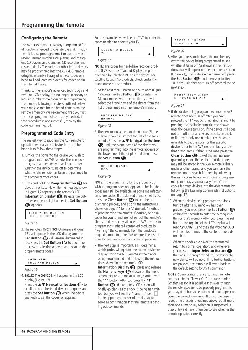
46 PROGRAMMING THE REMOTE
Configuring the RemoteThe AVR 435 remote is factory-programmed forall functions needed to operate the unit. In addi-tion, it is also preprogrammed to operate mostrecent Harman Kardon DVD players and chang-ers, CD players and changers, CD recorders andcassette decks. The codes for other brand devicesmay be programmed into the AVR 435 remoteusing its extensive library of remote codes or ahead-to-head learning process for codes not inthe internal library.
Thanks to the remote’s advanced technology and two-line LCD display, it is no longer necessary to look up cumbersome codes when programmingthe remote; following the steps outlined below,you simply search for the brand name from theremote’s memory. We recommend that you firsttry the preprogrammed code entry method. Ifthat procedure is not successful, then try thecode learning method.
Preprogrammed Code EntryThe easiest way to program the AVR remote for operation with a source device from anotherbrand is to follow these steps:
1. Turn on the power to the device you wish toprogram into the AVR remote. This is impor-tant, as in a later step you will need to seewhether the device turns off to determinewhether the remote has been programmed forthe proper remote codes.
2. Press and hold the Program Button & forabout three seconds while the message shown in Figure 15 appears in the remote’s LCDInformation Display 2. Release the but-ton when the red light under the Set ButtonF appears.
Figure 15
3. The remote’s MAIN MENU message (Figure16), will appear in the LCD display and theSet Button F will remain illuminated inred. Press the Set Button F to begin theprocess of selecting a device and locating theproper remote codes.
Figure 16
4. SELECT A DEVICE will appear in the LCDdisplay (Figure 17).Press the ⁄¤ Navigation Buttons E toscroll through the list of device categories andpress the Set Button F when the deviceyou wish to set the codes for appears.
For this example, we will select “TV” to enter thecodes needed to operate your TV.
Figure 17
NOTE: The codes for hard-drive recorder prod-ucts (PVR) such as TiVo and Replay are pro-grammed by selecting VCR as the device. Forsatellite-based TiVo products, check under thebrand name of the product.
5. At the next menu screen on the remote (Figure18) press the Set Button F to enter theManual mode, which means that you willselect the brand name of the device from thelist programmed into the remote’s memory.
Figure 18
6. The next menu screen on the remote (Figure19) will show the start of the list of availablebrands. Press the ⁄¤ Navigation ButtonsE until the brand name of the device youare programming into the remote appears onthe lower line of the display and then pressthe Set Button F.
Figure 19
NOTE: If the brand name for the product youwish to program does not appear in the list, thecodes may still be available, as some manufactur-ers share codes. If the desired brand is not listed,press the Clear Button # to exit the pro-gramming process, and skip to the instructionsshown on page 47 for the “Automatic” methodof programming the remote. If desired, or if thecodes for your brand are not part of the remote’slibrary at all, you may still use the AVR remote toprogram most infrared-controlled products by“learning” the commands from the product’soriginal remote into the AVR remote. The instruc-tions for Learning Commands are on page 47.
7. The next step is important, as it determineswhich codes will operate the source device ordisplay. Point the AVR remote at the devicebeing programmed and, following the instruc-tions shown in the remote’s LCDInformation Display 2, press and releasethe Numeric Keys H shown on the menuscreen (Figure 20) one at a time, starting withthe “1” button. After you press the “1”Button H, the remote’s LCD screen willbriefly go blank as the code is being transmit-ted, but you will see the “transmit” icon in the upper right corner of the display toserve as confirmation that the remote is send-ing out commands.
Figure 20
8. After you press and release the number key,watch the device being programmed to seewhether it turns off. As shown in the instruc-tions that will appear on the next menu screen(Figure 21), if your device has turned off, pressthe Set Button F, and then skip to Step10. If the unit does not turn off, proceed to thenext step.
Figure 21
9. If the device being programmed into the AVRremote does not turn off after you havepressed the “1” key, continue Steps 8 and 9 bypressing the available numeric keys shownuntil the device turns off. If the device still doesnot turn off after all choices have been tried,or if there is only one number key shown asavailable to try, the code for this specificdevice is not in the AVR remote library underthat brand name. If that is the case, press theClear Button # to exit the manual pro-gramming mode. Remember that the codesmay still be stored in the AVR remote’s libraryunder another brand, and you can have theremote control search for them by followingthe instructions below for automatic program-ming. You may also manually “learn” thecodes for most devices into the AVR remote byfollowing the Learning Commands instructionson page 47.
10. When the device being programmed doesturn off after a numeric key has beenpressed, you must press the Set Button Fwithin five seconds to enter the setting intothe remote’s memory. After you press the Setbutton, the top line of the LCD display willread SAVING… and then the word SAVED
will flash four times in the center of the bot-tom line.
11. When the codes are saved the remote willreturn to normal operation, and wheneveryou press the Input Selector Button 4that was just programmed, the codes for thenew device will be used. If no further buttonsare pressed, the remote will revert back tothe default setting for AVR commands.
NOTE: Some brands share a common remotecontrol code for “Power Off” for many models.For that reason it is possible that even thoughthe remote appears to be properly programmed,you may find that some buttons do not appear toissue the correct command. If this is the case,repeat the procedure outlined above, but if morethan one numeric key selection is suggested inStep 7, try a different number to see whether theremote operates correctly.
P O W E R O F F ? Y : S E T
N : N E X T # O R C L R
P R E S S A N U M B E R
C O D E 1 O F 1 0
S E L E C T B R A N D
R C A
P R O G R A M D E V I C E
M A N U A L
S E L E C T A D E V I C E
T V
M A I N M E N U
P R O G R A M D E V I C E
H O L D P R O G B U T T O N
F O R 3 S E C O N D S
Programming the Remote

PROGRAMMING THE REMOTE 47
Programming the Remote
Although the AVR remote is preprogrammed withan extensive library of codes for many majorbrands, it is also possible that you may haveattempted to program a product that is too newor too old, and thus not all of its commands willbe in the code library. You may fill in the codesfor any button that does not operate properly byusing the learning technique shown on page 47.
Automatic Code EntryIn addition to manual code selection using thebrand name list, it is also possible to automati-cally search through all the codes that are storedin the AVR remote’s library to see whether adevice will respond even if it is not listed amongthe brands that appear when you program theremote manually. To automatically searchthrough the codes that are available for a specificdevice type (e.g., DVD, VCR), follow these steps:
1. Turn on the power to the device you wish toprogram into the AVR remote. This is impor-tant, as in a later step you will need to seewhether the device turns off to determinewhether the remote has been programmed forthe proper remote codes.
2. Press and hold the Program Button & forabout three seconds while the message shownin Figure 15 appears in the remote’s LCDInformation Display 2. Release the but-ton when the red light under the Set ButtonF appears.
3. The remote’s MAIN MENU message (Figure16) will appear in the LCD display and the SetButton F will remain illuminated in red.Press the Set Button F to begin theprocess of selecting a device and locating theproper remote codes.
4. SELECT A DEVICE will appear in the LCD display (Figure 17).Press the ⁄¤ Navigation Buttons E toscroll through the list of device categories andpress the Set Button F when the devicefor which you wish to set the codes appears.For this example, we will select “TV” to enterthe codes needed to operate your TV.
5. At the next menu screen on the remote (Figure18), press the ⁄ Navigation Buttons Eso that the bottom line of the LCD displayreads AUTO (Figure 22) and then press theSet Button F to enter the Automatic pro-gramming mode.
Figure 22
6. As instructed on the next menu screen, press the ⁄ Navigation Buttons E to beginthe automatic code search process. Your con-firmation that the remote is sending out com-mands is the movement of a square blockacross the top line of the LCD display screenwhile the bottom line reads PLEASE WAIT….You will also see the transmit icon in the upper
right corner of the LCD display’s top line toremind you that the remote is working eventhough you may not see anything happeningto the device being programmed.
7. It will take a few seconds for the remote tosend out the first group of commands, afterwhich you will see a new display in the LCDscreen, as shown in Figure 23. Following theinstructions, if the device being programmedhas NOT turned off, press the ⁄ NavigationButtons E again to send another group ofcodes. If the device being programmed hasturned off, skip to Step 9.
Figure 23
8. By pressing the ⁄ Navigation Buttons Eagain, the remote will send out a new set ofcommands. When it pauses, follow the instruc-tions shown in Step 7. Depending on howmany codes are stored for a specific devicetype, you may have to repeat this process asmany as fifteen times. Remember, if the deviceturns off, skip to Step 9. When all the codes forthe device being programmed have been tried,the instruction shown in Figure 24 will appear.This means that the codes for the product youare trying to program are not in the AVRremote library and you will have to “learn”them into the remote following the instruc-tions shown on page 47. Press the SetButton F as instructed to exit the program-ming process.
Figure 24
9. If the device being programmed does turn offafter following the instructions in Step 7, you will need to verify the code set by pressing theNumeric Keys H in sequence, as instructedin Figure 23. Point the remote at the devicebeing programmed, and press the “1” ButtonH to see whether the device turns back on.
10. After pressing and releasing the “1” ButtonH, check to see whether the device hasturned back on. If it has, skip to Step 12. If itdoes not turn on, press the “2” Button H,or the next button in the numeric sequence ifyou are repeating the procedure, as instruct-ed by the LCD screen in Figure 25.
Figure 25
11. When pressing the “1” button does not turnthe device being programmed back on,repeat the procedure by trying the remainderof the Numeric Keys H in sequence, eachtime pressing and then releasing the buttonto see whether the new device turns back on.When it does, skip to the next step. However,if you try all 10 numeric keys and find thatthe unit will not turn on, you won’t be ableto use this method to program the device.Press the Clear Button # to exit theprogramming process. You’ll need to followthe Learning Commands instructions belowto enter the codes for this device into theAVR remote.
12. When pressing one of the numeric keys inStep 10 or 11 causes the device beingprogrammed to turn back on, follow theinstructions shown in Figure 22 and press theSet Button F within five seconds of thedevice turning on. After you press the Setbutton, the top line of the LCD display willread SAVING… and then the word SAVED
will flash four times in the center of thebottom line.
13. When the codes are saved, the remote willreturn to normal operation, and wheneveryou press the Input Selector Button 4that was just programmed, the codes for thenew device will be used. If no further buttonsare pressed, the remote will revert back tothe default setting for AVR commands.
Learning CommandsOn occasions when the AVR remote does notcontain the codes for a particular product’sremote in its built-in library, or when you wish toprogram a missing or special function into onebutton of a device, the AVR remote’s learningcapability allows you to do that. To teach com-mands from one product’s remote into the AVRremote, follow these steps:
The process requires that both the device’s origi-nal remote and the AVR remote be available.Before pressing any buttons on either remote,place them so that the IR transmitter on theremote from the device to be programmed is fac-ing the Infrared Lens 1 on the AVR’s remote.The two remotes should be no more than an inchapart, and there should not be any directsunlight or other bright light source near theremotes.
1. Press and hold the Program Button & forabout three seconds while the message shown in Figure 15 appears in the remote’s LCDInformation Display 2. Release the but-ton when the red light under the Set ButtonF appears.
2. The remote’s MAIN MENU message (Figure16), will appear in the LCD display and theSet Button F will remain illuminated inred. Press the ⁄ Navigation Buttons Eonce so that Learn appears on the bottom line
P O W E R O N ?
Y - > S E T N - > 1 ~ 0
R E A C H E N D P O I N T
E X I T - > S E T K E Y
P O W E R O F F ?
Y - > 1 ~ 0 N - >
P R O G R A M D E V I C E
A U T O

48 PROGRAMMING THE REMOTE
Programming the Remote
of the LCD screen, as shown in Figure 26.Press the Set Button F to begin theprocess of learning commands from anotherdevice’s remote into the AVR remote.
Figure 26
3. The SELECT A DEVICE message will appearin the LCD display (Figure 17). Press the ⁄¤
Navigation Buttons E to scroll throughthe list of device categories and press the SetButton F when the device for which youwish to set the codes appears. For this exam-ple, we will select “TV” to enter the codesneeded to operate your TV.
4. The next menu screen (Figure 27) will promptyou to select the button, or “key,” on the AVRremote that you wish to program. Press thatbutton on the AVR remote.
Figure 27
5. Once you press the button to be programmedon the AVR remote, press and hold the buttonon the remote control for the device to beprogrammed within five seconds, as instructedon the next menu screen (Figure 28).
Figure 28
6. Continue to hold the button on the originalremote until the menu on the AVR remote’sLCD screen changes. If the code is successfullylearned you will see the display shown inFigure 29. If you see that menu, proceed toStep 9. If the code is not successfully learned,you will see the display shown in Figure 30. Ifthat menu appears, proceed to Step 7.
Figure 29
Figure 30
7. If the message shown in Figure 26 appears in the display, press the Set Button F to tryprogramming the button again. When theremote prompts you to press and hold the keyon the original remote again by showing thedisplay shown in Figure 28, immediately pressthe button on the source remote again. Toavoid another failed attempt, make certainthat the windows on the two remotes are fac-ing one another.
8. Continue to hold the button on the originalremote until the AVR’s display changesagain. If the code was successfully learned,you will see the display shown in Figure 25.In that case, skip to the next step. If theLEARN FAILED display (Figure 30) appearsagain you may either try to program the keyagain, or press the ⁄ Navigation ButtonsE to stop the process. It is possible thatsome remotes may use code sequences orinfrared frequencies that are not compatiblewith the AVR remote, and those codes can-not be learned. When the display shown inFigure 31 appears, press the Set ButtonF to exit the Learning system.
Figure 31
9. When a code has been learned successfully,you have three options. When the displayshown in Figure 29 is on the LCD screen onthe AVR remote, you may press the SetButton F to learn additional codes fromthe buttons on a remote into the AVRremote. Follow Steps 4 through 8 as often asneeded to complete the code-learningprocess.
10. If you wish to change the name that appearsin the LCD display when the button that hasjust had a new code learned is pressed,press the ⁄ Navigation Buttons E sothat the display shown in Figure 32 appearsin the LCD display. Press the Set Button Fto open the RENAME KEY menu. Enter thenew name for the key following the instruc-tions shown in the Renaming Individual Keyssection of this manual on page 48. If you findit more convenient to rename the buttons at a later time, you may do that separately byfollowing the instructions on page 52.
Figure 32
11. When you have programmed all keys for thedesired device, press the ⁄ NavigationButtons E twice when the LEARN
MENU (Figure 29) appears so that you seethe display show in Figure 33. The remotewill return to normal operation.
Figure 33
12. If you wish to program the codes for anotherdevice, repeat the procedure outline above,but select a different device in Step 3.
Learning Codes for an InputSelector
The AVR 435’s remote allows you to learn a spe-cific code to be attached to one of the Input
Selectors 4 so that whenever that button ispressed, you will not only be selecting thatdevice as the AVR’s input and telling the remoteto use the remote codes that have been pro-grammed to belong to that device, it also allowsyou to have that special code transmitted, aswell. This allows you to have an input (or othercommand) sent to a display so that when videosources are directly connected to the display, youcan automatically command it to switch to thesame input selected for the AVR.
To learn a remote code into one of the InputSelectors 4, follow the same steps shownabove for learning the keys for an entire deviceremote with the following exceptions:
• In Step 3, press the ⁄/¤ NavigationButton E until LEARNDEVICEappears in the bottom line of the LCD display.
• When the SELECTA DEVICEmessage(Figure 26) appears, as described in Step 4,press the specific Input Selector Button4 that you wish to have transmit a specialcode when it is pressed.
• When the RENAMEDEVICE option isoffered by the remote after the code is pro-grammed, you will be changing the name thatis shown in the remote’s LCD display everytime that Input Selector is pressed.
Device PriorityAfter having programmed or learnt the differentsources, you can set the Device Priority. Thedefault setting is that after pressing one of theInput Selectors and any of its function keys, theremote control defaults back to controlling theAVR functions after 6 seconds. You can eitherextend this time to 12 seconds, or leave theremote control to control the last used source,by following the steps below.
1. Press and hold the Program Button &until the MAIN MENU appears.
2. Press the ¤ Navigation Button E untilDEVICE PRIORITY appears. Press the SetButton F.
3. Press the ⁄/¤ Navigation Button E toselect the requested setting. Confirm the set-ting by pressing the Set Button F.
Changing DevicesIn the factory default settings, the AVR remote is programmed so that the commands transmitted correspond to the device selected by pressingone of the Input Selectors 4. This is logical,as you want the remote to control the deviceyou have selected. However, in some circum-stances you may have configured your system sothat the devices connected to the AVR do notcorrespond to the default device settings andthe legends printed on the remote. For example,if your system has two VCRs you may connectthe second VCR to the VID 2 input. There is no
L E A R N M E N U
E N D L E A R N I N G
L E A R N M E N U
R E N A M E K E Y
L E A R N F A I L E D
E X I T
L E A R N F A I L E D
R E T R Y
L E A R N M E N U
L R N A N O T H E R K E Y
P R E S S K E Y O N
O R I G I N A L R E M O T E
S E L E C T A K E Y
T O P R O G R A M
M A I N M E N U
L E A R N

PROGRAMMING THE REMOTE 49
Programming the Remote
problem in doing that, but in normal operationthe commands issued after selecting the VID 2input are for a television, not a VCR.
The AVR remote allows you to correct that situa-tion through the “Changing Devices” process.That enables you to assign the codes from onetype of device to a different button. For example,in the steps below, we will explain how to pro-gram the VID 2 buttons to provide the commandsto operate a VCR. Of course, you may programthe remote to have any of the devices take onthe code set of any other device, as your systemrequires. And, with the AVR remote’s “Rename”function, you can even change the way the nameof the device appears on the remote’s LCD dis-play so that you see exactly which commands arebeing sent.
To program the buttons normally assigned to onedevice for the commands of another, follow thesesteps:
1. Press and hold the Program Button & forabout three seconds while the message shownin Figure 15 appears in the remote’s LCDInformation Display 2. Release the but-ton when the red light under the Set ButtonF appears.
2. The remote’s MAIN MENU message (Figure16), will appear in the LCD display and theSet Button F will remain illuminated inred. Press the ⁄ Navigation Buttons Etwice so that CHANGE DEVICE appears onthe bottom line of the LCD screen, as shown inFigure 34. Press the Set Button F to beginthe process of reassigning the commands usedfor a particular device.
Figure 34
3. The next menu display is where you select theInput Select, or device, that you wish tochange. When the display shown in Figure 35appears, press the ⁄¤ NavigationButtons E to scroll through the list to findthe device you wish to use for another func-tion. In this case we will select “TV,” and showhow to change it to take on the codes foroperating a VCR. When that device’s nameappears, press the Set Button F.
Figure 35
4. Once the “old” device type has been selected,you need to tell the remote which set ofremote codes to use as a replacement for thedevice just selected. When the instructionsshown in Figure 36 appear, press the ⁄¤
Navigation Buttons E to scroll throughthe list of device categories to find the nameof the device that you wish to use. The olddevice name will remain on the left side of theLCD screen, while the replacement device list
will scroll to its right. For example, press the⁄ Navigation Buttons E until the displayscreen reads TV<-VCR to have the VID 2/TVButton transmit the commands used to controla VCR. Press the Set Button F when thedesired device combination appears.
Figure 36
5. Once the new device is selected, the remain-der of the process will select the codes for thespecific brand to be used, and for that reasonthey are identical to the way a device is pro-grammed using manual entry. Continue theprocess as outlined in the next few steps,remembering that if the codes for your specificdevice are not found you may select any brandand then “learn” the proper codes into theAVR remote using the process outlined onpage 47. To begin the process, start by select-ing the brand of device, as shown in Figure 19.Press the ⁄¤ Navigation Buttons Euntil the brand name of the device you areprogramming into the remote appears on thelower line of the display and then press theSet Button F.
6. The next step is important, as it determineswhich codes will operate the source device ordisplay. Point the AVR remote at the devicebeing programmed and, following the instruc-tions shown on the remote’s LCDInformation Display 2, press and releasethe Numeric Keys H one at a time, start-ing with the “1” button. After you press the“1” Button H the remote’s LCD screen willbriefly go blank as the code is being transmit-ted, but you will see the “transmit” icon in theupper right corner of the display to serve asconfirmation that the remote is sending outcommands.
7. After you press and release the number key,watch the device being programmed to seewhether it turns off. As shown in the instruc-tions that will appear on the next menu screen(Figure 21), press the Set Button F, andthen skip to Step 9. If the unit does not turnoff, proceed to the next step.
8. If the device being programmed into the AVRremote does NOT turn off after you havepressed the “1” key, continue Steps 6 and 7 bypressing the available numeric keys shownuntil the device turns off. If the device still doesnot turn off after all choices have been tried,the code for this specific device is not in theAVR remote library under that brand name. Ifthat is the case, we suggest that you press theSet Button F to accept the codes fromanother brand so that the programming iscompleted, but remember that you will thenhave to program the remote manually by fol-lowing the Learning Commands instructionson page 47.
9. When the device being programmed doesturn off after a numeric key has beenpressed, you must press the Set Button Fwithin five seconds to enter the setting intothe remote’s memory. After you press the Setbutton, the top line of the LCD display willread SAVING... and then the word SAVED
will flash four times in the center of the bot-tom line.
10. When the codes are saved the remote willreturn to normal operation, and wheneveryou press the Input Selector Button 4that was just programmed, the display willshow the original device type code at the farleft side of the display, with the name of thenew code set type in brackets. For example,the display will read TV<-VCR in our exam-ple of replacing the TV codes with those for aVCR.
Macro ProgrammingMacros enable you to easily repeat frequentlyused combinations of multiple remote controlcommands with the touch of a single button.Once a macro is programmed you may send upto 20 commands with one press of the Power Onor Macro buttons. This will greatly simplify theprocess of turning on your system, changingdevices or other common tasks. Thanks to theremote’s two-line display, it is easier than everfor you to take advantage of the power of macrocommands.
Recording a MacroTo record a macro into the remote’s memory,follow these steps:
1. Press and hold the Program Button & forabout three seconds while the message shown in Figure 15 appears in the remote’s LCDInformation Display 2. Release thebutton when the red light under the SetButton F appears.
2. The remote’s MAIN MENU message (Figure16), will appear in the LCD display and theSet Button F will remain illuminated inred. Press the ⁄ Navigation Buttons Ethree times so that MACRO appears on thebottom line of the LCD screen, as shown inFigure 37. Press the Set Button F to enterthe main macro menu branch.
Figure 37
3. At the next menu screen (Figure 38) press the Set Button F to begin recording a macro.
Figure 38
4. The next display screen (Figure 39) is whereyou select the button that will be used torecall the macro. The choices are the PowerOn Button 3 or one of the discrete Macro
M A C R O
R E C O R D A M A C R O
M A I N M E N U
M A C R O
N E W D E V I C E T Y P E
T V < - V C R
O L D D E V I C E T Y P E
T V
M A I N M E N U
C H A N G E D E V I C E

50 PROGRAMMING THE REMOTE
Programming the Remote
Buttons . Press the ⁄¤ NavigationButtons E until the name of the buttonyou wish to program the macro into is shown.For this example we will show how to pro-gram a series of commands that will automat-ically be sent out every time the Power buttonis pressed.
Figure 39
5. The next screen that appears (Figure 40) iswhere you select the device for the first com-mand that will be sent out as part of themacro. Press the ⁄¤ Navigation ButtonsE until the name of the device appears onthe left side of the lower line in the LCD dis-play. For this example, the first button wewant to have the macro “press” is the PowerOn button, so the AVR device is selected.Press the Set Button F when the desireddevice name appears to move to the next pro-gramming step.
Figure 40
6. The next display (Figure 41) is where youbegin entering the individual commands forthe macro, in the order you wish them to betransmitted. Remember that when you wantto change devices, you must first press theInput Selector 45 for that button, andthen press the Command or Function key.Since we want to program a series of eventsthat occur each time the Power On button ispressed, press the AVR button. In your specificmacro, this is the first command button.
Figure 41
7. The next display (Figure 42) and the subse-quent screens are where the actual macroprogramming take place. The words at the leftside of the top line of the display show thebutton that is being programmed (e.g., thePower On Button 3 or one of the MacroButtons ) and the indication at the rightside of the top line shows the number ofmacro steps available of 20 possible steps.Following the instructions on the remote’sLCD screen, press the first key you wish to betransmitted in the macro. In our example, wefirst want the AVR to turn on, so the PowerButton 3 should be pressed.
Figure 42
8. Once the first command button for the macrohas been pressed, continue to press the but-tons you wish to be part of the macro, in the
order they will be used. Press each buttonwithin five seconds of the last button, remem-bering to press the Input Selector 45when you are changing device functions.As the buttons on the remote are pressed,the remote’s display screen will show thesteps in the macro as they are programmed(Figure 43).
Figure 43
9. For our example, we first want the AVR PowerOn button pressed, followed by the TV PowerOn, followed by the Cable Box On, followedby the selection of the Logic 7 mode. To dothat, press the buttons in this order:
• Power On 3• VID 2/TV 4• Power On 3• VID 3/Cable 4• Power On 3• AVR 5• Logic 7 O
As each button is pressed to enter it into themacro you will see the button names appearand then scroll up on the LCD display as yourconfirmation of the key entry (Figure 43).
10. When all commands for the macro havebeen entered, press the Set Button F tosave the macro. The display screen will showthe button to which the macro has been pro-grammed and the number of steps used, andthe word SAVED will blink four times in thelower line of the LCD display. When the dis-play returns to normal, the macro has beenentered and the remote is ready for opera-tion.
11. If a macro has been programmed into thePower On Button 3, it will play backanytime the Power On button is pressed. Asthe macro plays, you will see the stepsappear in the remote’s LCD display. Macrosprogrammed into one of the four discreteMacro buttons may be activated at any timeby pressing the appropriate button.
Erasing a MacroOnce a macro has been created and stored inthe AVR remote’s memory, you have the optionof erasing it. You may do this at any time by fol-lowing these steps:
1. Press and hold the Program Button & forabout three seconds while the messageshown in Figure 15 appears in the remote’sLCD Information Display 2. Release thebutton when the red light under the SetButton F appears.
2. The remote’s MAIN MENU message (Figure16), will appear in the LCD display and theSet Button F will remain illuminated inred. Press the ⁄ Navigation Buttons Ethree times so that MACRO appears on the
bottom line of the LCD screen, as shown inFigure 37. Press the Set Button F to enterthe main macro menu branch.
3. At the next menu screen (Figure 44) press⁄¤ Navigation Buttons E until thebottom line in the remote’s LCD display readsERASE A MACRO, as shown in Figure 44.Press the Set Button F to begin theprocess of erasing a macro.
Figure 44
4. The next display screen (Figure 45) is whereyou select which macro will be erased. Pressthe ⁄¤ Navigation Buttons E until thenumber of the macro you wish to eraseappears. For this example we will erase thePower On macro created in the previous sec-tion. When the name of the macro to beerased appears, press the Set Button F.
Figure 45
5. The word ERASED will flash four times in thebottom line of the remote’s LCD display, andthen the display will return to its normal con-dition. When that happens the macro iserased and the remote is returned to normaloperation.
Read a MacroTo check the commands stored in the remote’smemory for one of the buttons, follow thesesteps:
1. Press and hold the Program Button & forabout three seconds while the messageshown in Figure 15 appears in the remote’sLCD Information Display 2. Release thebutton when the red light under the SetButton F appears.
2. The remote’s MAIN MENU message (Figure16), will appear in the LCD display and theSet Button F will remain illuminated inred. Press the ⁄ Navigation Buttons Ethree times so that MACRO appears on thebottom line of the LCD screen, as shown inFigure 37. Press the Set Button F to enterthe main macro menu branch.
3. At the next menu screen (Figure 46) press the⁄¤ Navigation Buttons E until thebottom line in the remote’s LCD display showsREAD A MACRO, as shown in Figure 46.Press the Set Button F to begin theprocess of erasing a macro.
Figure 46
M A C R O
R E A D A M A C R O
E R A S E A M A C R O
P O W E R O N
M A C R O
E R A S E A M A C R O
[ A V R ]
[ A V R ] P O W E R O N
P O W E R O N 0 0 / 2 0
S E L E C T K E Y P R E S S
S E L E C T A D E V I C E
A V R
S E L E C T A D E V I C E
A V R
R E C O R D A M A C R O
P O W E R O N

PROGRAMMING THE REMOTE 51
Programming the Remote
4. The next display screen (Figure 47) is whereyou select the macro to be read. Press the⁄¤ Navigation Buttons E until thename of the macro you wish to read appears.For this example, we will read back the PowerOn macro created in the previous section.When the name of the macro to be erasedappears, press the Set Button F.
Figure 47
5. As soon as the Set button is pressed, the firsttwo steps in the macro will be appear in theremote’s LCD screen. You may then use the⁄¤ Navigation Buttons E to step up ordown through the list of commands stored asthe macro. As you read the display, you willsee Device Selector Buttons 45appear in brackets, (e.g., [AVR]). When thestep in the macro is a function, navigation orany other button, it will appear next to thebracketed read-out of the underlying device(e.g., [AVR] POWER ON).
6. When you are finished reviewing the macro’s contents, press the Set Button F to return the remote to normal operation.
Punch-Through ConfigurationPunch-through is a capability of the remote that allows the Volume controls, Channel Up/Downbuttons or Transport keys (Play, Stop, Record, FastForward and Reverse, and Skip Up/Down) to linkto a different device. For example, if your TV,cable box or satellite receiver is connectedthrough the AVR you will most likely want to usethe AVR’s volume control commands even whenthe remote has been set to issue all other com-mands for the video device. “Punch-through”enables you to easily program the remote to dothis.
Volume Punch-ThroughFollow these steps to enable the VolumeUp/Down and Mute controls from one device tobe used when the remote is otherwise pro-grammed for a different device.
Note for Volume Punch-Through:The remote’s default settings are for the AVR’svolume controls to be used when any input ordevice is selected with the exception of the VID2/TV button. There is no need to program theremote for volume punch-through for the AVR’scontrols with other sources, such as DVD. To havethe AVR’s volume commands used when the TVdevice is selected, follow these steps:
1. Press and hold the Program Button & forabout three seconds while the message shown in Figure 15 appears in the remote’s LCDInformation Display 2. Release the buttonwhen the red light under the Set Button Fappears.
2. The remote’s MAIN MENU message (Figure16), will appear in the LCD display and the
Set Button F will remain illuminated inred. Press the ⁄¤ Navigation ButtonsE until PUNCH-THROUGH appears on thebottom line of the LCD screen, as shown inFigure 48. Press the Set Button F to enterthe main punch-through menu branch.
Figure 48
3. At the next menu screen (Figure 49) press the Set Button F to begin programming theremote for Volume punch-through.
Figure 49
4. The next display screen (Figure 50) is whereyou select the device that will receive thepunch-through commands. In our example,that is the VID 2/TV button, as that is wherewe want the AVR’s volume controls to beactive. Press the ⁄¤ Navigation ButtonsE until the name of the base device appearsand then press the Set Button F.
Figure 50
5. At the next display screen (Figure 51), you willselect the device whose Volume Up/Down andMute commands will be used. Press the ⁄¤
Navigation Buttons E until the desireddevice’s name appears to the right of thedevice in use. In our example, that is the AVR(indicated by AVR). When the desired combination of devices appears, press the SetButton F.
Figure 51
6. When the Set button is pressed, the displaywill change to show you that the new combi-nation of control commands is being saved tothe unit’s memory, as shown in Figure 52. Theword SAVED will flash four times and thenthe remote will return to normal operation.
Figure 52
7. Once the punch-through is programmed, theVolume Up/Down and Mute buttons of thesecond device named will be used when thosebuttons ), are pressed while the masterdevice is in use.
Returning the Volume Control Settings to Default Operation:If you wish to remove the Volume punch-throughso that the commands for Volume and Mute arereturned to the factory default setting, follow the
steps shown above, except that in Steps 4 and 5,select the same device for both the DEVICE IN
USE on the left side of the bottom line and thePUNCH-THROUGH device. In the example used,the display to return the remote to default set-tings will appear as shown in Figure 53.
Figure 53
Channel Punch-ThroughChannel punch-through allows the ChannelUp/Down buttons to send commands to a differ-ent device than the one that has been selectedfor other commands. For example, you may wishto use a cable box or satellite receiver as thesource for a VCR, so you would want theChannel Up/Down Selectors + to transmitcommands to the cable box even though theother button commands are programmed tooperate the VCR.
To program the AVR for Channel punch-through,follow these steps. This example will show howto program channel punch-through so that thecommands programmed for Channel Up/Downfor the VID 3/ Cable device will be transmittedwhen the VID 1/VCR device has been selected asthe current device.
1. Press and hold the Program Button & forabout three seconds while the message shown in Figure 15 appears in the remote’s LCDInformation Display 2. Release the but-ton when the red light under the Set ButtonF appears.
2. The remote’s MAIN MENU message (Figure16), will appear in the LCD display and theSet Button F will remain illuminated inred. Press the ⁄¤ Navigation ButtonsE until PUNCH-THROUGH appears on thebottom line of the LCD screen, as shown inFigure 48. Press the Set Button F to enterthe main punch-through menu branch.
3. At the next menu screen, press the ⁄¤
Navigation Buttons E until CHANNEL
appears on the bottom line of the LCD screen,as shown in Figure 54. Press the Set ButtonF to begin programming the remote forChannel punch-through.
Figure 54
4. The next display screen (Figure 55) is whereyou select the device that will receive thepunch-through commands. In our example,that is the VID 1/VCR button, as that is wherewe want the cable box’s channel controls tobe active. Press the ⁄¤ NavigationButtons E until the name of the basedevice appears and then press the SetButton F.
P U N C H - T H R O U G H
C H A N N E L
P U N C H - T H R O U G H
T V < - T V
T V < - A V R [ V O L ]
S A V E D
P U N C H - T H R O U G H
T V < - A V R
D E V I C E I N U S E
T V
P U N C H - T H R O U G H
V O L U M E
M A I N M E N U
P U N C H - T H R O U G H
R E A D A M A C R O
P O W E R O N

52 PROGRAMMING THE REMOTE
Programming the Remote
Figure 55
5. At the next display screen (Figure 56), you willselect the device whose Channel Up/Downcommands will be used. Press the ⁄¤
Navigation Buttons E until the desireddevice name appears to the right of the devicein use. In our example, that is the cable box.When the desired combination of devicesappears, press the Set Button F.
Figure 56
6. When the Set button is pressed, the displaywill change to show you that the new combi-nation of control commands is being saved tothe unit’s memory, as shown in Figure 57. Theword SAVED will flash four times and thenthe remote will return to normal operation.
Figure 57
7. Once the punch-through is programmed, thechannel up/down buttons of the second devicenamed will be used when those buttons +are pressed while the master device is in use.
Returning the Channel Control Settings toDefault Operation:If you wish to remove the Channel Punch-Through so that the commands for ChannelUp/Down are returned to the factory default set-ting, follow the steps shown above, except thatin Steps 4 and 5, select the same device for boththe DEVICE IN USE on the left side of the bot-tom line and the PUNCH-THROUGH device. Inthe example used, the display to return theremote to default settings will appear as shownin Figure 58.
Figure 58
Transport Punch-ThroughTransport punch-through allows the Play P,Stop P, Fast Forward/Reverse P, PauseP, Record P and Skip Up/Down � but-tons to send commands to a different devicethan the one that has been selected for othercommands. For example, you may wish to oper-ate the transport of a second VCR you have con-nected to the VID 2/TV input, as shown in thefollowing example.
1. Press and hold the Program Button & forabout three seconds while the message shown in Figure 15 appears in the remote’s LCDInformation Display 2. Release the but-ton when the red light under the Set ButtonF appears.
2. The remote’s MAIN MENU message (Figure16), will appear in the LCD display and theSet Button F will remain illuminated inred. Press the ⁄¤ Navigation ButtonsE until PUNCH-THROUGH appears on thebottom line of the LCD screen, as shown inFigure 48. Press the Set Button F to enterthe main punch-through menu branch.
3. At the next menu screen, press the ⁄¤
Navigation Buttons E until TRANS-
PORT appears on the bottom line of the LCDscreen, as shown in Figure 59. Press the SetButton F to begin programming theremote for transport punch-through.
Figure 59
4. The next display screen (Figure 60) is whereyou select the device that will receive thepunch-through commands. In our example,that is the TV button, as that is where we wantthe VCR’s transport controls to be active. Pressthe ⁄¤ Navigation Buttons E until thename of the base device appears and thenpress the Set Button F.
Figure 60
5. At the next display screen (Figure 61), you willselect the device whose transport commandswill be used. Press the ⁄¤ NavigationButtons E until the desired device nameappears to the right of the device in use. In ourexample, that is the VCR. When the desiredcombination of devices appears, press the SetButton F.
Figure 61
6. When the Set button is pressed, the displaywill change to show you that the new combi-nation of control commands is being saved tothe unit’s memory, as shown in Figure 62. Theword SAVED will flash four times and thenthe remote will return to normal operation.
Figure 62
7. Once the punch-through is programmed, thetransport buttons of the second device namedwill be used when those buttons are pressedwhile the master device is in use.
Returning the Transport Control Settingsto Default Operation:If you wish to remove the Transport Punch-Through so that the transport commands arereturned to the factory default setting, follow thesteps shown above, except that in Steps 4 and 5,select the same device for both the DEVICE IN
USE on the left side of the bottom line and thePUNCH-THROUGH device. In the example used,the display to return the remote to default set-tings will appear as shown in Figure 63.
Figure 63
RenamingWhile the names given to the buttons and inputson the AVR represent recognizable categories ofaudio/ video products, system operation may beeasier if the displays shown in the remote’s LCDscreen are customized to reflect the specific char-acteristics of a playback source’s brand name orthe new function given to a specific button whenone remote’s controls are programmed into theAVR remote. The AVR remote allows you tochange the name of either a master device orany button on the remote using the followingsteps.
Renaming a DeviceTo rename a specific device/input source button,follow these steps. For this example, we willshow you how to rename the Device/InputSelector normally shown as “TV” to “HDTVTUNER.”
1. Press and hold the Program Button & forabout three seconds while the message shown in Figure 15 appears in the remote’s LCDInformation Display 2. Release the but-ton when the red light under the Set ButtonF appears.
2. The remote’s MAIN MENU message (Figure16), will appear in the LCD display and theSet Button F will remain illuminated inred. Press the ⁄¤ Navigation ButtonsE until RENAME appears on the bottomline of the LCD screen, as shown in Figure 66.
Figure 66
3. At the next menu screen press the ⁄¤
Navigation Buttons E until RENAME
DEVICE appears on the bottom line of theLCD screen, as shown in Figure 67. Press theSet Button F to begin renaming a device.
Figure 67
R E N A M E
R E N A M E D E V I C E
M A I N M E N U
R E N A M E
P U N C H - T H R O U G H
T V < - T V
T V < - V C R [ T R S ]
S A V E D
P U N C H - T H R O U G H
T V < - V C R
D E V I C E I N U S E
T V
P U N C H - T H R O U G H
T R A N S P O R T
P U N C H - T H R O U G H
V C R < - V C R
V C R < - C B L [ C H A N ]
S A V E D
P U N C H - T H R O U G H
V C R < - C B L
D E V I C E I N U S E
V C R

PROGRAMMING THE REMOTE 53
Programming the Remote
4. The next display screen (Figure 68) is whereyou select the device that will be renamed. Inour example, that is the TV button. Press the⁄¤ Navigation Buttons E until thename of the base device appears and thenpress the Set Button F.
Figure 68
5. At the next menu screen you will see thedevice name on the bottom line of the displaywith a blinking cursor box to the right of thedevice name. Press the ‹ NavigationButtons E to return the blinking cursor tothe far left side of the display line. You maythen retitle the device name as shown in thenext step.
6. To enter the new name, press the NumericKeys H. The letters above the numberedbuttons indicate which letter or symbol willappear when the button is pressed during therenaming process. The first press of the buttonwill enter the first letter shown, subsequentpresses of the same button will change thedisplay to the other letters above that num-bered key. For example, since the first letter weneed to rename the input to HDTV Tuner is an“H”, you would locate the “H” above the “4”button, and press the button twice. The firstpress shows a “G,” the second press changesit to an “H.” Consult the table at the end ofthis section to see which characters pressing aparticular button generates.
7. After you enter the first letter of the newdevice name, there are three options for enter-ing the next character:
a. To enter a letter that requires a different numeric key to be pressed, simply press thatbutton. The cursor will automatically moveto the next position and the first letteraccessed by the new button will appear.Following our example, the next letter need-ed is a “D,” so you would press the “3”button once.
b. To enter a letter that uses the same numerickey, you must first press the › NavigationButtons E to move the blinking cursorblock to the next position. Then press theNumeric Key H as required to enter thedesired letter.
c. To enter a blank space, press the ›Navigation Buttons E twice. The firstpress will move the cursor to the right, andthe second press will move the cursor onemore space to the right, leaving a blankspace between the last letter and the nextone.
8. Repeat Step 7 as needed to enter all theneeded letters, numbers, characters andspaces.
9. When the text entry is complete, press the Set Button F. The LCD display will blinkDEVICE RENAMED three times and thenreturn to normal operation.
Once a device is renamed you will see the newname on the top line of the remote’s LCD displaywhenever the Input/Device Selector 4 ispressed, or when any other command/functionbutton on the remote is pressed after the mainDevice Selector is pressed. Note that renaming adevice in the remote will not change the name ofthe input used by the on-screen menu system ofthe AVR.
Notes on Renaming Devices:• To move the cursor to the right or left of the
display during the renaming process, press the‹/› Navigation Buttons E as required.
• The table below shows the letters, numbersand characters that may be accessed by press-ing the Numeric Keys:
Key Characters Key Characters1 [,],/,1 6 M,N,O,62 A,B,C,2 7 P,Q,R,S,73 D,E,F,3 8 T,U,V,84 G,H,I,4 9 W,X,Y,Z,95 J,K,L,5 0 -,.,#,0
• Renaming a device changes the name of thedevice only, not any of the individual key func-tions within that device memory. To change thename of an individual device, follow theinstructions in the next section.
Renaming Individual KeysThanks to the programming flexibility of the AVRremote, an individual button on the remote maybe assigned a feature or function that is differentfrom the name that appears as the factorydefault when the button is pressed. However,with the Rename Key function it is possible torename almost any button on the remote so thatwhen the button is pressed you will see a moredescriptive or appropriate name displayed.
To rename a specific button on the remote, fol-low these steps. For this example, we will showyou how to rename the Tone Control Button., which is normally not used when DVD isselected so that it reads ZOOM in the remote’sdisplay.
1. Press and hold the Program Button & forabout three seconds while the message shown in Figure 15 appears in the remote’s LCDInformation Display 2. Release the but-ton when the red light under the Set ButtonF appears.
2. The remote’s MAIN MENU message (Figure16), will appear in the LCD display and theSet Button F will remain illuminated inred. Press the ⁄¤ Navigation ButtonsE until RENAME appears on the bottomline of the LCD screen, as shown in Figure 66.
3. At the next menu screen press the ⁄¤
Navigation Buttons E until RENAME
KEY appears on the bottom line of the LCD
screen, as shown in Figure 69. Press the SetButton F to continue.
Figure 69
4. The next display screen (Figure 70) is whereyou select the device within which the key tobe renamed exists. Press the ⁄¤
Navigation Buttons E until the name ofthe base device appears. In our example, sincewe want to rename a button within the DVDdevice memory, DVD should appear in thelower line of the LCD. When the desired devicename appears, press the Set Button F.
Figure 70
5. At the next menu screen you will select thefirst button within the device to be renamed,as instructed in the display shown in Figure71. Select the button by simply pressing it onthe remote.
Figure 71
6. Depending on whether or not the buttonpressed already has a named function withinthe device selected, one of two things willhappen.
a. If the button to be renamed already has apre-programmed, or previously renamedtitle in the remote’s memory, you will seethat name on the top line of the LCD dis-play, and a blinking block cursor will appearon the far left side of the bottom line of thedisplay, as shown in Figure 72.
b. If the button to be renamed does not have afunction in the device selected, the top lineof the LCD screen will be blank, and a blink-ing block cursor will appear on the far leftside of the bottom line of the display, asshown in Figure 73.
Figure 72
Figure 73
7. To enter the new name for the key, press theNumeric Keys H. The letters above thenumbered buttons indicate which letters orsymbols will appear when the button ispressed during the renaming process. The firstpress of the button will enter the first charac-ter shown, subsequent presses of the samebutton will change the display to the other let-ters above that numbered key. For example,
D I S C S K I P
S E L E C T A K E Y
S E L E C T A D E V I C E
D V D
R E N A M E
R E N A M E K E Y
R E N A M E D E V I C E
T V

54 PROGRAMMING THE REMOTE
Programming the Remote
since the first letter we need to rename theTone button to Zoom is a “Z,” so you wouldlocate the “Z” above the “9” button, andpress the button four times. The first pressshows a “W,” the subsequent presses stepthrough the other letters available until the“Z” appears. Consult the table on this page tosee which characters are available by pressinga particular button.
8. After you enter the first letter of the newdevice name, there are three options forentering the next character:
a. To enter a letter that requires a differentnumeric key to be pressed, simply press thatbutton. The cursor will automatically moveto the next position and the first letteraccessed by the new button will appear.Following our example, the next letter need-ed is an “O,” so you would press the “6”button once.
b. To enter a letter that uses the same numerickey, you must first press the › NavigationButtons E to move the blinking cursorblock to the next position. Then press theNumeric Key H as required to enter thedesired letter. This is the way you wouldenter the second “O” in the word ZOOM,and again for the letter “M.”
c. To enter a blank space, press the ›Navigation Buttons E twice. The firstpress will move the cursor to the right, andthe second press will move the cursor onemore space to the right, leaving a blankspace between the last letter and the nextone.
9. Repeat Steps 7 and 8 as needed to completeentering the needed letters, numbers, charac-ters and spaces.
10. When the text entry is complete, press theSet Button F. The new name will beentered into the remote’s memory, replacingthe default name.
11. At this point you have two options:
a. If you wish to program an additional keywithin the same device, press the SetButton F as instructed by the bottomline of the LCD display reading ANOTHER
KEY. The remote will return to the SELECT
A KEY menu option as shown in Step 6.Repeat the instructions in Steps 6 though11 to rename the next key.
b. If you have no additional keys to rename,press the ⁄ Navigation Buttons Eonce so that the menu screen displays EXIT
on the bottom line of the display. Press theSet Button F to return the remote tonormal operation.
Notes on Renaming Keys:• Renaming a key does not change its function.
You may change the function of an individualkey by learning a new code into the remote.See page 34 for more information.
• When a key is renamed it will only apply to the specific device selected in Step 4. The same keymay be renamed as needed for each individualdevice with which it is used.
Resetting the RemoteDepending on the way in which the remote hasbeen programmed, there may be a situationwhere you wish to totally erase all changes thathave been made to the remote and return it tothe factory defaults. You may do that by follow-ing the steps shown below, but remember thatonce the remote is reset, ALL changes that havebeen made, including programming for use withother devices, learned keys, macros, punch-through settings and key names, will be erasedand any settings you had previously made willhave to be reentered.
To erase all settings and reset the remote to the original factory default settings and displays, fol-low these steps:
1. Press and hold the Program Button & forabout three seconds while the message shown in Figure 15 appears in the remote’s LCDInformation Display 2. Release the but-ton when the red light under the Set ButtonF appears.
2. The remote’s MAIN MENU message (Figure16), will appear in the LCD display and theSet Button F will remain illuminated inred. Press the ⁄¤ Navigation ButtonsE until USER RESET appears on the bot-tom line of the LCD screen, as shown in Figure74.
Figure 74
3. Press the Set Button F to reset theremote. Note that once the Set Button ispressed the process may not be stopped. Whilethe remote’s memory is being cleared aRESETTING... message will appear in theupper line of the remote’s LCD screen asshown in Figure 75.It may take a few minutes for the reset process to take place, and the length of time will varydepending on how much customization and programming has taken place. Please bepatient; as long as the message appears in thedisplay the remote is functioning properly.
Figure 75
4. When the remote has been totally reset andreturned to the factory default condition, aREMOTE RESET COMPLETE message willappear (Figure 76) briefly, and then the remotewill return to normal operation.
Figure 76
Backlight Options
The AVR 435’s remote has a built-in backlightsystem that makes it easier to use the remotewhen the room lighting is dimmed for an optimalhome theater experience. To turn the backlight-ing on, simply press the Light Button Q. Thatbutton is made from a special “glow” materialthat makes it easier to find in dark rooms. Thisglow feature does not use any battery power, sothe glow will fade when the remote is kept in adark room for an extended period of time. Youmay “recharge” it by placing the remote in nor-mal room lighting for a few hours.
Once the Light Button Q is pressed, theremote’s backlighting will remain on for approxi-mately 7 seconds, and when you press any but-ton on the remote while the backlighting is on,the light will stay on for another 7 seconds.However, the remote’s “Couch” function willconserve battery power by turning both the back-lighting and the LCD display off when any buttonis pressed for more than 30 seconds.
You may also configure the remote so that thebacklighting will come on, any time a button ispressed.To set this option, follow these steps:
1. Press and hold the Program Button & forabout 3 seconds while the message shown inFigure 24 appears in the remote’s LCD display.Release the button when the red light underthe Set Button F appears.
2. When the remote’s Main Menu message (Fig.25) appears in the LCD display and the SetButton F remains illuminated in red, pressthe ⁄¤ Navigation Buttons E untilBACKLIGHT appears in the bottom lineof the LCD screen, as shown in Figure 77.
Figure 77
3. Press the Set Button F and then pressthe⁄¤ Navigation Buttons E again sothat ONFULL appears in the bottom line ofthe LCD display, as shown in Figure 78.
Figure 78
B A C K L I G H T
O N F U L L
M A I N M E N U
B A C K L I G H T
R E M O T E R E S E T
C O M P L E T E
R E S E T T I N G . . .
M A I N M E N U
U S E R R E S E T
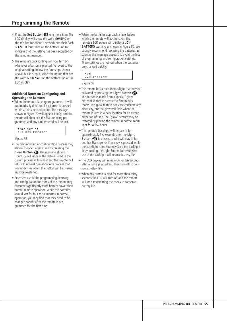
PROGRAMMING THE REMOTE 55
Programming the Remote
4. Press the Set Button F one more time. TheLCD display will show the word SAVING onthe top line for about 2 seconds and then flashSAVED four times on the bottom line toindicate that the setting has been accepted bythe remote’s memory.
5. The remote’s backlighting will now turn onwhenever a button is pressed. To revert to theoriginal setting, follow the four steps shownabove, but in Step 3, select the option that hasthe word NORMAL on the bottom line of theLCD display.
Additional Notes on Configuring andOperating the Remote:• When the remote is being programmed, it will
automatically time-out if no button is pressedwithin a thirty-second period. The messageshown in Figure 79 will appear briefly, and theremote will then exit the feature being pro-grammed and any data entered will be lost.
Figure 79
• The programming or configuration process may also be stopped at any time by pressing theClear Button #. The message shown inFigure 79 will appear, the data entered in thecurrent process will be lost and the remote willreturn to normal operation. Any process thatwas underway when the button will be pressedmust be re-started.
• Extensive use of the programming, learningand configuration functions of the remote mayconsume significantly more battery power thannormal remote operation. While the batteriesshould last for four to six months in normaloperation, you may find that they need to bechanged sooner after the remote is pro-grammed for the first time.
• When the batteries approach a level belowwhich the remote will not function, theremote’s LCD screen will display a LOW
BATTERY warning as shown in Figure 80. Westrongly recommend replacing the batteries assoon as this message appears to avoid the lossof programming and configuration settings.These settings are not lost when the batteriesare changed quickly.
Figure 80
• The remote has a built-in backlight that may be activated by pressing the Light Button Q.This button is made from a special “glow”material so that it is easier to find in darkrooms. This glow feature does not consume anyelectricity, but the glow will fade when theremote is kept in a dark location for an extend-ed period of time. The “glow” feature may berestored by placing the remote in normal roomlight for a few hours.
• The remote’s backlight will remain lit forapproximately five seconds after the LightButton Q is pressed, and it will stay lit foranother five seconds if any key is pressed whilethe backlight is on. You may keep the backlightlit by holding the Light Button, but extensiveuse of the backlight will reduce battery life.
• The LCD display will remain on for ten secondsafter a key is pressed and then turn off to con-serve battery life.
• When any button is held for more than thirtyseconds the LCD will turn off and the remotewill stop transmitting the codes to conservebattery life.
A V R
L O W B A T T E R Y
T I M E O U T O R
C L R K E Y P R E S S E D

56 TROUBLESHOOTING GUIDE
Troubleshooting Guide
Processor Reset
In the rare case where the unit’s operation or thedisplays seem abnormal, the cause may involvethe erratic operation of the system’s memory ormicroprocessor.
To correct this problem, first unplug the unit fromthe AC wall outlet and wait at least threeminutes. After the pause, reconnect the ACpower cord and check the unit’s operation. If thesystem still malfunctions, a system reset mayclear the problem.
To clear the AVR’s entire system memory includ-ing tuner presets, output level settings, delaytimes and speaker configuration data, first putthe unit in Standby by pressing the SystemPower Control button 2. Next, press theSurround Mode 5 and the RDS ^ buttonssimultaneously.
The unit will turn on automatically and displaythe RESETmessage in the Main Infor-mation Display ˜. Note that once you havecleared the memory in this manner, it is necessaryto re-establish all system configuration settingsand tuner presets.
NOTE: Resetting the processor will erase anyconfiguration settings you have made forspeakers, output levels, surround modes, digitalinput assignments as well as the tuner presets.After a reset the unit will be returned to thefactory presets, and all settings for these itemsmust be reentered.
If the system is still operating incorrectly, theremay have been an electronic discharge or severeAC line interference that has corrupted thememory or microprocessor.
If these steps do not solve the problem, consultan authorized Harman Kardon service depot.
SYMPTOM CAUSE SOLUTION
Unit does not function when Main • No AC Power • Make certain AC power cord is plugged Power Switch 1 is pushed into a live outlet
• Check to see if outlet is switch controlled
Display lights, but no sound • Intermittent input connections • Make certain that all input and speaker or picture connections are secure
• Mute is on • Press Mute button ,• Volume control is down • Turn up volume control
Units turns on, but Front-Panel • Display brightness is turned off • Follow the instructions in the Display Brightness section Display does not light on page 41 so that the display is set to VFDFULL
No sound from any speaker; • Amplifier is in protection mode • Check speaker-wire connections for shorts at receiver light around Power switch 2 is red due to possible short and speaker ends
• Amplifier is in protection mode • Contact your local Harman Kardon service depotdue to internal problems
No sound from surround or • Incorrect surround mode • Select a mode other than Stereocenter speakers • Input is mono • There is no surround information from mono sources (except with
Theater and Hall surround modes)• Incorrect configuration • Check speaker mode configuration• Stereo or Mono program material • Some surround modes may not create rear-channel information
from nonencoded programs
Unit does not respond to • Weak batteries in remote • Change remote batteriesremote commands • Wrong device selected • Press the AVR Selector 5
• Remote sensor ¯ is obscured • Make certain front-panel sensor is visible to remote or connect remote sensor
Intermittent buzzing in tuner • Local interference • Move unit or antenna away from computers, fluorescent lights,motors or other electrical appliances
Letters flash in the Channel Indicator • Digital audio feed paused • Resume play for DVDDisplay Ú and Digital Audio stops • Check that Digital Signal is fed to the Digital Input selected

TECHNICAL SPECIFICATIONS 57
Technical Specifications
Audio SectionStereo Mode Continuous Average Power (FTC)
80 Watts per channel, 20Hz–20kHz,@ < 0.07% THD, both channels driven into 8 ohms
5/7 Channel Surround Modes Power Per Individual Channel
Front L&R channels:65 Watts per channel,@ < 0.07% THD, 20Hz–20kHz into 8 ohms
Center channel:65 Watts, @ < 0.07% THD, 20Hz–20kHz into 8 ohms
Surround (L & R Side, L & R Back) channels:65 Watts per channel,@ < 0.07% THD, 20Hz–20kHz into 8 ohms
Input Sensitivity/Impedance Linear (High Level) 200mV/47kohms
Signal-to-Noise Ratio (IHF-A) 95dB
Surround System Adjacent Channel Separation Analog Decoding 40dB (Pro Logic, etc.) Dolby Digital (AC-3) 55dB DTS 55dB
Frequency Response @ 1W (+0dB, –3dB) 10Hz–130kHz
High Instantaneous Current Capability (HCC) ±40 Amps
Transient Intermodulation Distortion (TIM) Unmeasurable
Rise Time 16 µsec
Slew Rate 40V/µsec**
FM Tuner SectionFrequency Range 87.5–108MHzUsable Sensitivity IHF 1.3 µV/13.2dBfSignal-to-Noise Ratio Mono/Stereo: 70/68dB (DIN)Distortion Mono/Stereo: 0.15/0.2%Stereo Separation 40dB @ 1kHzSelectivity ±400kHz: 70dBImage Rejection 80dBIF Rejection 90dB
AM Tuner SectionFrequency Range 520–1710kHzSignal-to-Noise Ratio 45dBUsable Sensitivity Loop: 500µVDistortion 1kHz, 50% Mod: 0.8%Selectivity ±10kHz: 30dB
Video SectionVideo Format PAL/NTSCInput Level/Impedance 1Vp-p/75 ohmsOutput Level/Impedance 1Vp-p/75 ohmsVideo Frequency Response(Composite and S-Video) 10Hz–8MHz (–3dB)Video Frequency Response (Component) 10Hz-50MHz (-3dB)
GeneralPower Requirement AC 220-240V/50HzPower Consumption 59W idle, 1040W maximum
(7 channels driven)
Dimensions (Max)Width 440mm Height 165mm Depth 435mm Weight 17.7 kg
Depth measurement includes knobs, buttons and terminal connections.Height measurement includes feet and chassis.All features and specifications are subject to change without notice.
Harman Kardon and Power for the Digital Revolution are registered trademarks of Harman International Industries, Incorporated.
is a trademark of Harman International Industries, Inc.(Patent No. 5,386,478).
*Manufactured under license from Dolby Laboratories.“Dolby,” “Pro Logic,” “Pro Logic II,” "Pro Logix IIx" and the Double-D symbol are trademarks of Dolby Laboratories. Confidential Unpublished Works. ©1992–1999 Dolby Laboratories, Inc. All rights reserved.
DTS and DTS Surround, DTS-ES and DTS Neo:6 are trademarks of Digital Theater Systems, Inc.
Logic 7 is a registered trademark of Harman International Industries, Incorporated.
A-BUS and A-BUS Ready are registered trademarks of Leisure Tech Electronics Pty Ltd Australia.
TiVo is a registered trademark of TiVo, Inc.
Replay TV is a registered trademark of Digital Networks North America, Inc.
**Without input anti slewing and output isolation networks.
Supplied AccessoriesThe following accessory items are supplied with the AVR 435.If any of these items are missing, please contact Harman Kardon customer service at www.harmankardon.com.
• A system remote control• A Zone II remote control• An microphone• Extender rod for microphone• An AM loop antenna• An FM wire antenna• Six AAA batteries

250 Crossways Park Drive, Woodbury, New York 11797 www.harmankardon.comHarman Consumer Group International:2, route de Tours, 72500 Château-du-Loir, France© 2005 Harman Kardon, Incorporated Part No.: ZKD2001HA00-2


