32
AVS Anchor ® -L Lumbar Cage System Surgical Technique

AVS Anchor®-L Lumbar Cage System Surgical Technique

AVS Anchor-L Lumbar Cage SystemSurgical Technique
2
Table of Contents
Introduction . . . . . . . . . . . . . . . . . . . . . . . . . . . . . . . . . . . . . . . . . . . . . . . . . . . . . . . . . 3
Preoperative Planning . . . . . . . . . . . . . . . . . . . . . . . . . . . . . . . . . . . . . . . . . . . . . . . . . 4
Approach – Transperitoneal or Retroperitoneal . . . . . . . . . . . . . . . . . . . . . . . . . . . 4
Cage Height Determination . . . . . . . . . . . . . . . . . . . . . . . . . . . . . . . . . . . . . . . . . . . . 4
Step 1: Exposure . . . . . . . . . . . . . . . . . . . . . . . . . . . . . . . . . . . . . . . . . . . . . . . . . . . . . . 4
Step 2: Perform the Annulotomy & Discectomy . . . . . . . . . . . . . . . . . . . . . . . . . . . 5
Step 3: Prepare the Endplates . . . . . . . . . . . . . . . . . . . . . . . . . . . . . . . . . . . . . . . . . . . 6
Step 4: Determine Cage Size . . . . . . . . . . . . . . . . . . . . . . . . . . . . . . . . . . . . . . . . . . . . 6
Step 5: Load the Cage . . . . . . . . . . . . . . . . . . . . . . . . . . . . . . . . . . . . . . . . . . . . . . . . 10
Step 6: Insert the Cage . . . . . . . . . . . . . . . . . . . . . . . . . . . . . . . . . . . . . . . . . . . . . . . . 13
Step 7: Prepare the Screw Pathway . . . . . . . . . . . . . . . . . . . . . . . . . . . . . . . . . . . . . . 14
Step 8: Insert the Screws . . . . . . . . . . . . . . . . . . . . . . . . . . . . . . . . . . . . . . . . . . . . . . 15
Step 9: Remove the AIOG . . . . . . . . . . . . . . . . . . . . . . . . . . . . . . . . . . . . . . . . . . . . . 16
Step 10: Insert the Locking Plate . . . . . . . . . . . . . . . . . . . . . . . . . . . . . . . . . . . . . . . 17
Implant Removal . . . . . . . . . . . . . . . . . . . . . . . . . . . . . . . . . . . . . . . . . . . . . . . . . . . . 18
Standard Instruments . . . . . . . . . . . . . . . . . . . . . . . . . . . . . . . . . . . . . . . . . . . . . . . . 19
Standard Implants . . . . . . . . . . . . . . . . . . . . . . . . . . . . . . . . . . . . . . . . . . . . . . . . . . . 22
Auxiliary Instruments . . . . . . . . . . . . . . . . . . . . . . . . . . . . . . . . . . . . . . . . . . . . . . . . 23
Auxiliary Implants . . . . . . . . . . . . . . . . . . . . . . . . . . . . . . . . . . . . . . . . . . . . . . . . . . . 25
Indications for Use . . . . . . . . . . . . . . . . . . . . . . . . . . . . . . . . . . . . . . . . . . . . . . . . . . . 27
Contraindications, Cautions and Pre-Operative Cautions . . . . . . . . . . . . . . . . . . 27
Acknowledgments
Stryker Spine wishes to thank the following surgeons for their dedication and contributions to the development of the AVS Anchor-L Lumbar Cage System .
Glenn Amundson, MD
Alexander Bailey, MD
Douglas Beard, MD
Alexandre De Moura, MD
John Gorup, MD
Robert Josey, MD
Dan Lee, MD

3
AVS Anchor-L Lumbar Cage SystemSurgical Technique
Introduction
The Stryker Spine AVS Anchor-L Lumbar Cage System includes a PEEK cage, three titanium bone screws, and a titanium locking plate that will be used together as an interbody fusion device for the lumbosacral spine (L2-S1) . The PEEK cage incorporates three tantalum markers that aid in radiographic visualization . These markers are positioned on the posterior end and lateral aspects of the cage . The markers span the total height of the cage in order to show the overall height relative to the vertebral endplates as well as the cage-to-endplate proximity . The upper and lower aspects of the lumbar cage are open, and the superior and inferior surfaces have serrations that assist in positive anchorage and seating . The AVS Anchor-L PEEK cage and titanium bone screws are available in a variety of sizes in order to allow the surgeon to choose those that are best suited to the patient’s anatomy and pathology .
The AVS Anchor-L device is designed to be inserted via a transperitoneal or retroperitoneal surgical approach to the lumbosacral spine . After the cage is implanted, the bone screws should be inserted, and then the construct is locked with a titanium locking plate once it is determined that the construct is in its desired final position .
The AVS Anchor-L Lumbar Cage System may be used as an intervertebral device with integrated fixation or in conjunction with supplemental fixation . When used as a intervertebral device with integrated fixation, the AVS Anchor-L PEEK Cage must be used with three internal screws and plate fixation provided by AVS Anchor-L Fixation Screws and Locking Plate . If AVS Anchor-L is used with less than three or none of the provided screws, additional supplemental fixation that has been cleared by the FDA for use in the lumbosacral spine must be used to augment stability . The accompanying Locking Plate must be used anytime the device is used with any number of screws.

AVS Anchor-L Lumbar Cage SystemSurgical Technique
4
Preparation
Approach - Transperitoneal or Retroperitoneal
Determine surgical approach (transperitoneal or retroperitoneal) . Surgeon preference, patient anatomy, and patient pathology should determine the approach used .
The Reliance AL Instruments can be used in either a transperitoneal or retroperitoneal approach to the lumbosacral spine and may depend on which level of the spine is being treated . Anterior access is required for the insertion of the screws and locking plate . This technique details a retroperitoneal approach .
Cage Height Determination
Analyze preoperative imaging to determine height of the cage . The cage must be firmly seated with a secure fit in the disc space when the segment is distracted .
Step 1: Exposure
Expose the midline of the intervertebral disc . Take care to expose the segment with sufficient space on either side of the midline to allow for placement of the device (widths range from 30mm – 40mm) (Fig. 1) .
Consideration: Mark the midline of the disc/vertebral body under fluoroscopic guidance. This mark will assist in determining the annulotomy site width (Fig. 2).
Figure 1
Figure 2

5
AVS Anchor-L Lumbar Cage SystemSurgical Technique
Step 2: Perform the Annulotomy & Discectomy
Using the Long Handle Knife (Reliance AL 48361277) cut a window in the annulus . It is important that the window is centered on the vertebral midline in order to prepare the position for the implant (Fig. 3) .
Figure 3. Long Handle Knife48361277
Warning: Care is required while performing the annulotomy with the Long Handle Knife as the blade can result in serious damage to the vascular elements.Blades for the Long Handle Knife are not included with the Reliance AL System.
A cobb can be used to separate the cartilaginous endplate from the bony vertebral endplate (Fig. 4) .
Use a pituitary rongeur to remove disc material . To accommodate a range of needs, pituitary rongeurs are available in sizes of 4mm and 8mm, and in three different orientations; up, down, and straight . The pituitary rongeurs can also be used to remove disc material and cartilaginous tissue from the superior and inferior vertebral endplates .
A paddle distractor or a lordosed paddle distractor may be used to distract and allow room to work on the contralateral side .
Curettes can also be used to remove disc material and cartilage from the superior and inferior vertebral endplates . Curettes are offered in straight, up and upward bend orientations .
Note: The Reliance AL Lumbar Fusion System includes instruments used during annulotomy, discectomy, bone removal, and endplate preparation. These instruments include cobbs, pituitary rongeurs, kerrisons, paddle distractors, curettes, and rasps. (See Reliance AL Surgical Technique for information regarding these instruments.)
Once the discectomy has been performed, the Posterior Longitudinal Ligament (PLL) Stripper may be used . The instrument may be used to release the PLL from the posterior edge of both the upper and lower vertebral bodies if deemed necessary by the surgeon . The value of releasing the PLL is to optimize parallel distraction and to permit maximum opening of the space for neural elements if required . If the PLL Stripper is utilized, use caution to protect the neurological structures (Fig. 5) .
Figure 5. Posterior Longitudinal Ligament (PLL) Stripper48361238
Distraction of the discectomy site is important to restore lordosis, open the neural foramen, and stabilize the implant . The Reliance AL Discectomy Distractor can be used to provide distraction for the discectomy, endplate preparation, implant trialing, and implant insertion . The Modular Straight Tips or Offset Tips are recommended (Fig. 6) .
Figure 6. Reliance AL Discectomy Distractor48361150
Figure 4. Cobb
Figure 3. Long Handle Knife
AVS Anchor-L Lumbar Cage SystemSurgical Technique
6
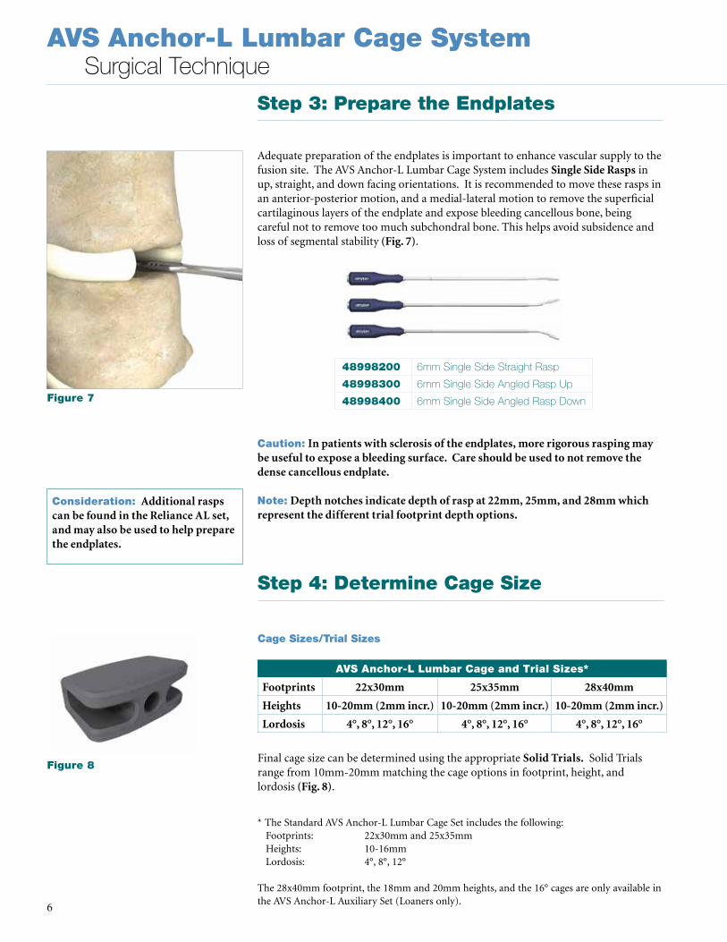
Step 3: Prepare the Endplates
Adequate preparation of the endplates is important to enhance vascular supply to the fusion site . The AVS Anchor-L Lumbar Cage System includes Single Side Rasps in up, straight, and down facing orientations . It is recommended to move these rasps in an anterior-posterior motion, and a medial-lateral motion to remove the superficial cartilaginous layers of the endplate and expose bleeding cancellous bone, being careful not to remove too much subchondral bone . This helps avoid subsidence and loss of segmental stability (Fig. 7) .
Caution: In patients with sclerosis of the endplates, more rigorous rasping may be useful to expose a bleeding surface. Care should be used to not remove the dense cancellous endplate.
Note: Depth notches indicate depth of rasp at 22mm, 25mm, and 28mm which represent the different trial footprint depth options.
Step 4: Determine Cage Size
Cage Sizes/Trial Sizes
Final cage size can be determined using the appropriate Solid Trials. Solid Trials range from 10mm-20mm matching the cage options in footprint, height, and lordosis (Fig. 8) .
AVS Anchor-L Lumbar Cage and Trial Sizes*
Footprints 22x30mm 25x35mm 28x40mm
Heights 10-20mm (2mm incr.) 10-20mm (2mm incr.) 10-20mm (2mm incr.)
Lordosis 4°, 8°, 12°, 16° 4°, 8°, 12°, 16° 4°, 8°, 12°, 16°
48998200 6mm Single Side Straight Rasp
48998300 6mm Single Side Angled Rasp Up
48998400 6mm Single Side Angled Rasp Down
* The Standard AVS Anchor-L Lumbar Cage Set includes the following: Footprints: 22x30mm and 25x35mm Heights: 10-16mm Lordosis: 4°, 8°, 12°
The 28x40mm footprint, the 18mm and 20mm heights, and the 16° cages are only available in the AVS Anchor-L Auxiliary Set (Loaners only) .
Consideration: Additional rasps can be found in the Reliance AL set, and may also be used to help prepare the endplates.
Figure 7
Figure 8

7
AVS Anchor-L Lumbar Cage SystemSurgical Technique
The Trial Handle can be used for trial insertion . The Trial Stop was designed to prevent the trial from being inserted too posteriorly which may inaccurately represent the position of the implant when placed with the All-In-One Guide (AIOG) . Once the Trial Stop has been placed onto the Trial Handle, attach the trial by threading the distal end into the hole in the trial . Insert the trial into the disc space to confirm the appropriate size cage . Fluoroscopy can assist in confirming the proper fit (Fig. 9) .
If the trial appears too small or too tight, the next larger or smaller size, respectively, should be chosen until the firmest fit is obtained . The Solid Trial can be removed from the Trial Handle by unthreading the trials from the handle .
Note: If using the AVS Anchor-L lumbar cage as an anterior lumbar cage with supplemental fixation, do not use the Trial Stop during trialing. Without the Trial Stop, the trials can be countersunk into the disc space to give an accurate representation of where the final implant will sit (Fig. 10).
Figure 9. Trial Handle48361234
Consideration: Lateral imaging is recommended for confirming posterior trial-to-endplate contact. There should be no gaps between the endplates and the trial (Fig. 11).
Consideration: It is important to not oversize with the trial, as the overall implant height is 1mm taller than the trial when the height of the serrations (0.5mm per side) is included.
Figure 10. Trial Stop48991014
Figure 11

AVS Anchor-L Lumbar Cage SystemSurgical Technique
8
AVS Anchor-L Anterior vs. Posterior Height
22mm x 30mm footprint
Size
Ant height [mm]
Post height [mm]
Difference Ant/Post
[mm]
Nose Height [mm]
10mm x 4° 10 8.9 1.1 6.8
10mm x 8° 10 7.8 2.2 5.5
10mm x 12° 10 6.7 3.3 4.1
12mm x 4° 12 10.9 1.1 8.8
12mm x 8° 12 9.8 2.2 7.5
12mm x 12° 12 8.7 3.3 6.1
12mm x 16° 12 7.6 4.5 4.7
14mm x 4° 14 12.9 1.1 10.8
14mm x 8° 14 11.8 2.2 9.5
14mm x 12° 14 10.7 3.3 8.1
14mm x 16° 14 9.6 4.5 6.7
16mm x 4° 16 14.9 1.1 12.8
16mm x 8° 16 13.8 2.2 11.5
16mm x 12° 16 12.7 3.3 10.1
16mm x 16° 16 11.6 4.5 8.7
18mm x 4° 18 16.9 1.1 14.8
18mm x 8° 18 15.8 2.2 13.5
18mm x 12° 18 14.7 3.3 12.1
18mm x 16° 18 13.6 4.5 10.7
20mm x 4° 20 18.9 1.1 16.8
20mm x 8° 20 17.8 2.2 15.5
20mm x 12° 20 16.7 3.3 14.1
20mm x 16° 20 15.6 4.5 12.7
Anchor-L Height Specifications
Post
erio
r Hei
ght
(Bas
e of
Tee
th)
Nose
Hei
ght
Ante
rior H
eigh
t (B
ase
of T
eeth
)

9
AVS Anchor-L Lumbar Cage SystemSurgical Technique
AVS Anchor-L Anterior vs. Posterior Height
25mm x 35mm footprint
Size
Ant height [mm]
Post height [mm]
Difference Ant/Post
[mm]
Nose Height [mm]
10mm x 4° 10 8.7 1.3 6.6
10mm x 8° 10 7.4 2.6 5.0
10mm x 12° 10 6.0 4.0 3.5
12mm x 4° 12 10.7 1.3 8.6
12mm x 8° 12 9.4 2.6 7.0
12mm x 12° 12 8.0 4.0 5.5
12mm x 16° 12 6.7 5.3 3.9
14mm x 4° 14 12.7 1.3 10.6
14mm x 8° 14 11.4 2.6 9.0
14mm x 12° 14 10.0 4.0 7.5
14mm x 16° 14 8.7 5.3 5.9
16mm x 4° 16 14.7 1.3 12.6
16mm x 8° 16 13.4 2.6 11.0
16mm x 12° 16 12.0 4.0 9.5
16mm x 16° 16 10.7 5.3 7.9
18mm x 4° 18 16.7 1.3 14.6
18mm x 8° 18 15.4 2.6 13.0
18mm x 12° 18 14.0 4.0 11.5
18mm x 16° 18 12.7 5.3 9.9
20mm x 4° 20 18.7 1.3 16.6
20mm x 8° 20 17.4 2.6 15.0
20mm x 12° 20 16.0 4.0 13.5
20mm x 16° 20 14.7 5.3 11.9
AVS Anchor-L Anterior vs. Posterior Height
28mm x 40mm footprint
Size
Ant height [mm]
Post height [mm]
Difference Ant/Post
[mm]
Nose Height [mm]
10mm x 4° 10 8.5 1.5 6.4
10mm x 8° 10 6.9 3.1 4.6
10mm x 12° 10 5.4 4.6 2.8
12mm x 4° 12 10.5 1.5 8.4
12mm x 8° 12 8.9 3.1 6.6
12mm x 12° 12 7.4 4.6 4.8
12mm x 16° 12 5.9 6.1 3.0
14mm x 4° 14 12.5 1.5 10.4
14mm x 8° 14 10.9 3.1 8.6
14mm x 12° 14 9.4 4.6 6.8
14mm x 16° 14 7.9 6.1 5.0
16mm x 4° 16 14.5 1.5 12.4
16mm x 8° 16 12.9 3.1 10.6
16mm x 12° 16 11.4 4.6 8.8
16mm x 16° 16 9.9 6.1 7.0
18mm x 4° 18 16.5 1.5 14.4
18mm x 8° 18 14.9 3.1 12.6
18mm x 12° 18 13.4 4.6 10.8
18mm x 16° 18 11.9 6.1 9.0
20mm x 4° 20 18.5 1.5 16.4
20mm x 8° 20 16.9 3.1 14.6
20mm x 12° 20 15.4 4.6 12.8
20mm x 16° 20 13.9 6.1 11.0

AVS Anchor-L Lumbar Cage SystemSurgical Technique
10
Note: It will be important to use the Marking Guides in the orientation that the screws will eventually be inserted.
Note: All Marking Guides have 16° of lordosis. The design intent is to avoid posteriorly over distracting a lordotic disc space.
Note: It is important to use the appropriate size Marking Guide relative to the implant height, as using a height that is shorter than the disc space could allow the guide to advance too far posteriorly.
10x22x30° Marking Guide 48999102
10x25x35° Marking Guide 48990102
12x22x30° Marking Guide 48999126
14x22x30° Marking Guide 48999146
12x25x35° Marking Guide 48990126
Step 5: Load the Cage
Once the final cage size has been determined, select the corresponding AVS Anchor-L PEEK cage from the tray . Place the cage into the appropriate footprint on the Graft Block (Fig. 15), and use the Graft Impactor (Fig. 16) to pack autogenous bone graft into the open cavities of the cage (Fig. 14) .
Figure 15. Graft Block48999010
Figure 16. Graft Impactor48999020
14x25x35° Marking Guide 48990146
10x28x40° Marking Guide* 48991102
12x28x40° Marking Guide* 48991126
14x28x40° Marking Guide* 48991146
*Included in the Auxilary Instrument Set only .
After trialing, if it is determined that a 10mm, 12mm, or 14mm cage will be implanted, a Marking Guide can be used to aid surgeons in identifying the areas of bone from the superior and inferior vertebral bodies that will need to be removed to allow for accurate screw insertion . Attach the appropriate Marking Guide (height and footprint matching the cage size determined by trialing) to the Trial Handle . Insert the Marking Guide into the disc space . Once the guide has marked the areas of bone needing to be removed, remove the guide (Fig. 12) . Referencing the notches created by the Marking Guide, use a rongeur to remove any bone that may interfere with screw placement (Fig. 13) .
Figure 12
Figure 13
Figure 14
Figure 12. Marking Guide

11
AVS Anchor-L Lumbar Cage SystemSurgical Technique
Option 1: Interbody Technique
After the cage has been packed with bone graft, attach the cage to the Implant Holder by placing the distal end of the holder onto the front of the cage and then depressing the lever arm to tighten the arms into the lateral grooves on the cage (Fig. 17) .
With the leading edge of the cage slightly between the vertebral endplates, gently impact the proximal end of the Implant Holder to safely and gradually insert the cage .
Reminder: If any screws are used, the Locking Plate must be inserted. If less than three screws are used, supplemental fixation that is cleared for use in the lumbosacral spine must be utilized.
Figure 17. Implant Holder48992001
AVS Anchor-L Graft Volume
22mm x 30mm footprint
Size 4° 8° 12° 16°
10mm 1.6 1.5 1.4 -
12mm 2.1 2.0 1.9 1.7
14mm 2.5 2.4 2.2 2.2
16mm 2.9 2.8 2.7 2.6
18mm 3.3 3.2 3.1 3.0
20mm 3.8 3.6 3.5 3.4
AVS Anchor-L Graft Volume
25mm x 35mm footprint
Size 4° 8° 12° 16°
10mm 2.4 2.2 2.0 -
12mm 3.1 2.9 2.7 2.5
14mm 3.7 3.5 3.3 3.1
16mm 4.3 4.1 3.9 3.7
18mm 5.0 4.7 4.5 4.3
20mm 5.6 5.4 5.2 5.0
AVS Anchor-L Graft Volume
28mm x 40mm footprint
Size 4° 8° 12° 16°
10mm 3.4 3.0 2.7 -
12mm 4.4 4.1 3.7 3.4
14mm 5.3 4.9 4.6 4.3
16mm 6.2 5.8 5.5 5.1
18mm 7.1 6.7 6.4 6.0
20mm 7.9 7.6 7.3 6.9
Anchor-L Graft Volumes

AVS Anchor-L Lumbar Cage SystemSurgical Technique
12
Figure 23. AIOG Holder48992000
Note: Any screwdriver in the set, in addition to the Small Locking Driver, may be used to tighten or loosen the AIOG Locking Screw at any point during the procedure, as these screws also have a 3.5mm hex interface.
By fully tightening the AIOG Locking Screw, the AIOG is firmly attached to the cage . Be sure that the AIOG is flush with the anterior wall of the implant . Attach the AIOG Holder to the AIOG cage construct by using the quick release feature of the AIOG Holder .
Note: The AIOG Locking Screw is a separate piece, and may thread completely out. This allows for cleaning should tissue become lodged in the threads. If a Locking Screw (Fig. 22) is misplaced, simply use one of the extra Locking Screws in the set, or a Locking Screw from a different size AIOG.
Tip: If the Locking Screw will not advance, back it up one turn, slightly depress the gold arm of the AIOG, and then advance the Locking Screw. The AIOG Locking Screw should not be over-tightened.
Option 2: Stand Alone Technique
After the cage has been packed with bone graft, attach the appropriate height All-In-One Guide (AIOG) to the cage by aligning the laser marking on the AIOG arm with the corresponding laser marking on the side of the cage (Fig. 18) . The AIOG is locked to the cage by using the AIOG Small Locking Driver (Fig. 19) to tighten the AIOG Locking Screw . (Fig. 20)
Figure 20. AIOG Locking Screw48992110
Figure 19. AIOG Small Locking Driver48992115
Note: The AIOG’s are cage height specific. There are six AIOG’s. For example, if a 12mm cage is to be implanted, the 12mm AIOG must be used (Fig. 21).
10mm All In One Guide 48992010
12mm All In One Guide 48992012
14mm All In One Guide 48992014
16mm All In One Guide 48992016
18mm All In One Guide* 48992018
20mm All In One Guide* 48992020
*Included in the Auxiliary Instrument Set only .
Note: The Implant Holder can be used instead of the AIOG to insert the cage if it is being used as an interbody fusion device with supplemental fixation in place of the internal bone screws and locking plate (Fig. 23).
Figure 22. AIOG Locking Screw48992110
Figure 18
Figure 21

13
AVS Anchor-L Lumbar Cage SystemSurgical Technique
Step 6: Insert the Cage
AVS Anchor-L is designed with a beveled leading edge to assist in initial distraction during insertion . If additional distraction is needed, the Reliance AL Discectomy Distractor with Modular Straight or Offset Tips may be used . With the leading edge of the cage slightly between the vertebral endplates, gently impact the proximal end of the AIOG Holder to safely and gradually insert the cage (Fig. 25) .
Figure 25. Insertion into the Disc Space
The AVS Anchor-L lumbar cage was designed to be implanted with either one cephalad screw and two caudal screws (Fig. 26), or one caudal screw and two cephalad screws (Fig. 27) . This allows the surgeon the flexibility to choose screw orientation based on each patient’s individual anatomy and pathology . This feature also decreases the chance of screw interference when used at two contiguous levels .
Note: The orientation of the cage and screws with one cephalad screw and two caudal screws is recommended especially at L5-S1 due to the difficult trajectory of the L5 screw and the location of the vessels.
Note: The sleeves of the AIOG are fully covered to help ensure that the awl, drill, tap, and screwdriver are properly guided into the vertebral endplate.
Final cage positioning can be verified with the help of fluoroscopy intraoperatively . Once the cage is in its desired position, release the AIOG Holder from the AIOG by using the quick release feature on the handle (Fig. 28) .
Note: The AIOG features a mechanical stop in order to 1) prevent the cage from being implanted too posteriorly, and 2) potentially maximize screw purchase by creating an entry point closer to the anterior vertebral wall (Fig. 24).
1.5mm 1.5mm
1.5mm
Figure 26. 2 Caudal / 1 Cephalad(2 Barrels Cephalad / 1 Barrel Caudal)
2 Barrels Cephalad
Figure 27. 1 Caudal / 2 Cephalad(1 Barrel Cephalad / 2 Barrels Caudal)
1 Barrel Cephalad
Figure 24
Figure 28

AVS Anchor-L Lumbar Cage SystemSurgical Technique
14
Step 7: Prepare the Screw Pathway
AVS Anchor-L is designed with three screw holes located at the anterior wall of the implant . The location of these holes relative to the superior and inferior aspects of the cage is consistent on every implant size in order to ensure a consistent vertebral wall entry point in every case . This entry point is designed to be the anterior most portion of the vertebral body, or the apophyseal ring, and may allow the surgeon to potentially achieve more optimal purchase in the bone .
Connect the Round Ratchet Handle (Fig. 29) to the proximal end of either the Modular Rigid or Flexible Awl . Prepare the vertebral body for screw insertion by applying pressure on the handle of the Awl in conjunction with rotational motions until the Awl reaches a positive stop within the AIOG . The Awl length before the positive stop is 15mm . The depth awled will always be 7 .4mm (Fig. 30) .
Figure 29. Round Ratchet Handle48231302
Modular Rigid Awl48999110
Modular Rigid Drill48999150
Modular Rigid Tap48999250
Modular Flexible Awl48994110
Modular Flexible Drill48994150
Modular Flexible Tap48994250
7.4mm
Note: The Round Ratchet Handle can be set to a non-ratcheting setting depending on surgeon preference. In addition, any Xia 3 handle may be used with the Anchor-L modular shaft instruments (Fig. 31).
Awl Dimensions
Overall Length 15mm
Depth in Bone 7.4mm
Diameter 2.6mm
Drill Dimensions
Overall Length 20mm
Depth in Bone 15mm
Diameter 2.6mm
Figure 30
Figure 31 Figure 32

15
AVS Anchor-L Lumbar Cage SystemSurgical Technique
Note: In cases where the anatomy requires additional preparation, the Modular Rigid or Flexible Drill and/or Tap may be used. The Drill tip features a positive stop. The diameter of the Drill is 2.6mm, and the total length before the positive stop is 20mm. The depth drilled will always be 15mm. The Tap tip features a black laser marking that will align with the AIOG when the Tap has been fully inserted. The positive stop on the Tap is located 2mm beyond the laser etched line as a safety precaution. It is recommended to tap only the laser etched line (depth of 15mm) to avoid potential stripping (Fig. 31 and Fig. 32).
Note: Should the screw hole get accidentally stripped, a 6.0mm screw may be utilized to increase purchase.
Step 8: Insert the Screws
The AVS Anchor-L Lumbar Cage System offers Ø5 .0mm screws in lengths of 20mm, 25mm and 30mm (Fig. 33) . In addition, Ø6 .0mm screws in the same lengths are available should the surgeon need to revise a screw (Fig. 34) .
Figure 33. Ø5.0mm
Figure 34. Ø6.0mm AVS Anchor-L Fixation Screws
48665020 Bone Screw 5.0mm x 20mm
48665025 Bone Screw 5.0mm x 25mm
48665030 Bone Screw 5.0mm x 30mm
These screws feature a cortical/cancellous dual lead thread pattern and have a cutting flute at the tip to aid in insertion . This feature makes these screws self-drilling and self-tapping . Once the three screws have been placed, lateral fluoroscopy may be used to verify the final positioning of the screws (Fig. 35) .
Note: There are several different screwdriver options available for placing the screws in order to meet surgeon preference and accommodate varying patient anatomy.
Figure 36. Modular Rigid Screwdriver48999000
Figure 37. Modular Flexible Screwdriver48994000
Figure 38. Modular U-Joint Driver 48999002
48666020 Bone Screw 6.0mm x 20mm
48666025 Bone Screw 6.0mm x 25mm
48666030 Bone Screw 6.0mm x 30mm
STANDARD SCREWDRIVERS
1. The Modular Rigid (Fig. 36) and Flexible Screwdrivers (Fig. 37) and the U-Joint Driver (Fig. 38) each have a black laser marking that will align with the AIOG when the screw has been fully inserted.
Tap Dimensions
Overall Length 20mm
Depth in Bone 15mm
Diameter 5mm
Figure 35

AVS Anchor-L Lumbar Cage SystemSurgical Technique
16
Figure 39. 3.5mm Modular Hex Round Tip Rigid Screwdriver*48999003
Figure 40. 3.5mm Modular Hex Round Tip Flexible Screwdriver48994003
Figure 41. 90° Angled Screwdriver* 48990005
SPECIAL ORDER SCREWDRIVERS
1. The Rigid and Flexible 3.5mm Hex Round Tip Screwdrivers are compatible with the AIOG, but they do not have a black laser mark line to indicate when the screw is fully inserted. These screwdrivers are ideally used for screw adjustments if necessary after the AIOG is removed. The 3.5mm Hex Round Tip Drivers interface with the screw head up to 30° off axis, which may allow for easier access at challenging levels (Fig. 39 and Fig. 40).*
2. The 90° Angled Screwdriver is not compatible with the AIOG and does not have a black laser mark to indicate screw positioning (Fig. 41).*
Step 9: Remove the AIOG
Once the screws have been inserted, re-attach the AIOG Inserter to the shaft of the AIOG using the quick release feature . Any Screwdriver may be used to loosen the AIOG Locking Screw . With the AIOG Locking Screw loosened, carefully pull the AIOG out of the surgical site .
Caution: It is only necessary to loosen the AIOG locking screw 2-3 full rotations in order to detach it from the cage. Avoid over-loosening, as this could result in the gold arm releasing and potentially contacting surrounding soft tissue.
Note: If the AIOG does not easily remove from the cage after loosening the Locking Screw, apply a gentle rocking motion from side to side to detach from the cage (Fig. 42).
*Special order only
Figure 42. Loosening the Locking Screw Removing the All-in-One Guide

17
AVS Anchor-L Lumbar Cage SystemSurgical Technique
*Special order only
Note: If any of the screws need additional turns for final positioning, the Rigid or Flexible 3.5mm Hex Round Tip Screwdrivers may be used. These drivers are designed to quickly and easily find the head of the screw and allow collinear force to continue to advance the screw in its initial insertion trajectory up to 30° off axis (Fig. 43).
Figure 43. 3.5mm Hex Round Tip Rigid andFlexible Screwdrivers*
Measurements of Screw Protruding from Cage
Screw oriented at 35° Screw oriented at 40° Screw oriented at 45°
20mm 25mm 30mm 20mm 25mm 30mm 20mm 25mm 30mm
22x30 4.7 mm 8.8 mm 13.0 mm 3.4 mm 7.2 mm 11.0 mm 1.8 mm 5.4 mm 8.9 mm
25x35 1.7 mm 5.8 mm 10.0 mm 0.3 mm 4.2 mm 8.0 mm -1.2 mm 2.4 mm 5.9 mm
28x40 1.3 mm 2.8 mm 6.9 mm -2.6 mm 1.2 mm 5.0 mm -4.1 mm -0.6 mm 2.9 mm
Note: Some of the measurements have negative value. The screw is therefore not protruding from the cage in that particular case.
Step 10: Insert the Locking Plate
The AVS Anchor-L locking plate was designed to be simple and easy to use . The plate is “one size fits all,” and should be inserted after all three screws have been placed in their desired positions . Attach the Plate Inserter to the locking plate by placing the distal prongs inside the two holes on the plate, and depressing the lever arm . This action squeezes or pinches the plate to a width smaller than the locking tabs on the front of the cage (Fig. 44) .Figure 44. Plate Inserter
48997010
Caution: It is recommended to load the locking plate onto the Plate Inserter with the plate laying on a flat surface; either inside the tray or on a table in the sterile field . Because the plate pinches, there is the potential to catch a glove in the slots as they are compressed if the plate is held during loading .
Using caution to avoid damage to the vascular elements, place the locking plate firmly onto the front of the cage . With the locking plate contacting the cage, gently release the lever arm in order to allow the locking plate to regain its original shape underneath the PEEK locking tabs .
Figure 43

AVS Anchor-L Lumbar Cage SystemSurgical Technique
18
Tip: It is recommended to slip one side of the locking plate underneath the PEEK locking tabs, lower the contralateral side, then release the lever arm . This helps guide the plate more easily into its final locked position (Fig. 45) .
Caution: Minimize the number of plate deformations as repetitive deformations may jeopardize the integrity of the plate .
The locked position of the locking plate may be verified using the Plate Feeler (Fig. 46) . Insert the prong of the Plate Feeler into the holes on the locking plate and exert gentle upward force to confirm that the plate is locked . Fluoroscopy may be used at this time to verify final positioning .
Note: It is recommended to check both holes on the locking plate in order to confirm the security of the plate.
Note: If a surgeon wishes to use the AVS Anchor-L lumbar cage with less than three or none of the screws provided, supplementary fixation that is cleared for use in the lumbosacral spine must be utilized. If using supplementary fixation with screws, care must be taken regarding the trajectory of the supplementary fixation and any AVS Anchor-L screws. Use the Implant Holder to insert the cage and then introduce supplementary fixation. If any screws are used, the locking plate must be inserted.
As a reminder, all tantalum markers are positioned 1 .5mm from the edges of the cage . For example, there is an additional 1 .5mm of PEEK extending beyond the posterior tantalum marker in the image to the left (Fig. 47) .
Figure 46. Plate Feeler48997020
Implant Removal
If the implant needs to be removed, first use the Plate Inserter to remove the locking plate . Engage the distal prongs into the holes on the plate, depress the lever arm to pinch the plate, and lift the plate off the cage .
Next, use the Rigid or Flexible 3 .5mm Hex Tip Screwdriver to engage with the screw heads and back out the screws . Once the screw heads are more accessible, it is recommended to use the Rigid or Flexible Screwdrivers, as these are self-holding and will maintain control of the screw during removal (Fig. 48) .
After all screws have been removed, use the Implant Holder to grasp the sides of the cage by depressing the handle and locking the instrument to the cage . Carefully remove the cage from the disc space . If necessary, use a mallet to back the cage out .
Figure 47. Posterior Tantalum Marker
Figure 48
Figure 45

19
AVS Anchor-L Lumbar Cage SystemSurgical Technique
Set Definition
Standard Set Definition
Instruments Reference # Description
48998200 6mm Single Side Straight Rasp
48998300 6mm Single Side Angled Rasp Up
48998400 6mm Single Side Angled Rasp Down
48992104 10x22x30x4° Trial
48992108 10x22x30x8° Trial
48992102 10x22x30x12° Trial
48992124 12x22x30x4° Trial
48992128 12x22x30x8° Trial
48992122 12x22x30x12° Trial
48992144 14x22x30x4° Trial
48992148 14x22x30x8° Trial
48992142 14x22x30x12° Trial
48992164 16x22x30x4° Trial
48992168 16x22x30x8° Trial
48992162 16x22x30x12° Trial
48993104 10x25x35x4° Trial
48993108 10x25x35x8° Trial
48993102 10x25x35x12° Trial
48993124 12x25x35x4° Trial
48993128 12x25x35x8° Trial
48993122 12x25x35x12° Trial
48993144 14x25x35x4° Trial
48993148 14x25x35x8° Trial
48993142 14x25x35x12° Trial
48993164 16x25x35x4° Trial
48993168 16x25x35x8° Trial
48993162 16x25x35x12° Trial

AVS Anchor-L Lumbar Cage SystemSurgical Technique
20
Instruments Reference # Description
48999102 10x22x30° Marking Guide
48990102 10x25x35° Marking Guide
48999126 12x22x30° Marking Guide
48999146 14x22x30˚ Marking Guide
48990126 12x25x35° Marking Guide
48990146 14x25x35° Marking Guide
48361234 Trial Handle
48991014 Trial Stop
48999010 Graft Block
48999020 Graft Impactor
48992010 10mm All In One Guide
48992012 12mm All In One Guide
48992014 14mm All In One Guide
48992016 16mm All In One Guide
48992110 AIOG Locking Screw
48992000 AIOG Holder
48992115 AIOG Screwdriver
48992001 Implant Holder
48999110 Modular Rigid Awl
48999150 Ø5mm Modular Rigid Drill
48999250 Ø5mm Modular Rigid Tap
48994110 Modular Flexible Awl
48994150 Ø5mm Modular Flexible Drill
48994250 Ø5mm Modular Flexible Tap
48999000 Modular Rigid Screwdriver
48999002 Modular U-Joint Driver
48994000 Modular Flexible Screwdriver
48231301 Xia 3 Round Handle
48231302 Xia 3 Ratchet Round Handle
48997010 Plate Inserter
48997020 Plate Feeler
Standard Set Definition

21
AVS Anchor-L Lumbar Cage SystemSurgical Technique
Instruments Reference # Description
48993000 Implant Tray Lid
48993002 Implant Tray Top Insert
48993003 Implant Tray Bottom Insert
48993001 Implant Tray Base
48991000 Instrument Tray Lid
48991002 Instrument Tray Top Insert
48991003 Instrument Tray Bottom Insert
48991001 Instrument Tray Base
Special Order Only - Instruments Reference # Description
48990005 90° Angled Screwdriver
48990006 90° Angled Screwdriver Gear Cover
48999003 3.5mm Modular Hex Round Tip Rigid Screwdriver
48994003 3.5mm Modular Hex Round Tip Flexible Screwdriver
Standard Set Definition
AVS Anchor-L Lumbar Cage SystemSurgical Technique
22
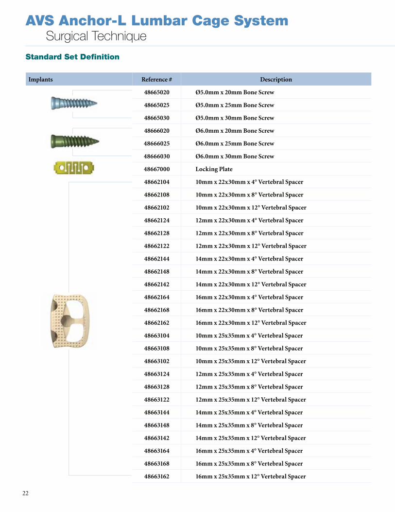
Implants Reference # Description
48665020 Ø5.0mm x 20mm Bone Screw
48665025 Ø5.0mm x 25mm Bone Screw
48665030 Ø5.0mm x 30mm Bone Screw
48666020 Ø6.0mm x 20mm Bone Screw
48666025 Ø6.0mm x 25mm Bone Screw
48666030 Ø6.0mm x 30mm Bone Screw
48667000 Locking Plate
48662104 10mm x 22x30mm x 4° Vertebral Spacer
48662108 10mm x 22x30mm x 8° Vertebral Spacer
48662102 10mm x 22x30mm x 12° Vertebral Spacer
48662124 12mm x 22x30mm x 4° Vertebral Spacer
48662128 12mm x 22x30mm x 8° Vertebral Spacer
48662122 12mm x 22x30mm x 12° Vertebral Spacer
48662144 14mm x 22x30mm x 4° Vertebral Spacer
48662148 14mm x 22x30mm x 8° Vertebral Spacer
48662142 14mm x 22x30mm x 12° Vertebral Spacer
48662164 16mm x 22x30mm x 4° Vertebral Spacer
48662168 16mm x 22x30mm x 8° Vertebral Spacer
48662162 16mm x 22x30mm x 12° Vertebral Spacer
48663104 10mm x 25x35mm x 4° Vertebral Spacer
48663108 10mm x 25x35mm x 8° Vertebral Spacer
48663102 10mm x 25x35mm x 12° Vertebral Spacer
48663124 12mm x 25x35mm x 4° Vertebral Spacer
48663128 12mm x 25x35mm x 8° Vertebral Spacer
48663122 12mm x 25x35mm x 12° Vertebral Spacer
48663144 14mm x 25x35mm x 4° Vertebral Spacer
48663148 14mm x 25x35mm x 8° Vertebral Spacer
48663142 14mm x 25x35mm x 12° Vertebral Spacer
48663164 16mm x 25x35mm x 4° Vertebral Spacer
48663168 16mm x 25x35mm x 8° Vertebral Spacer
48663162 16mm x 25x35mm x 12° Vertebral Spacer
Standard Set Definition

23
AVS Anchor-L Lumbar Cage SystemSurgical Technique
Instruments Reference # Description
48992018 18mm All In One Guide
48992020 20mm All In One Guide
48992126 12x22x30x16° Trial
48992146 14x22x30x16° Trial
48992166 16x22x30x16° Trial
48992184 18x22x30x4° Trial
48992188 18x22x30x8° Trial
48992182 18x22x30x12° Trial
48992186 18x22x30x16° Trial
48992204 20x22x30x4° Trial
48992208 20x22x30x8° Trial
48992202 20x22x30x12° Trial
48992206 20x22x30x16° Trial
48993126 12x25x35x16° Trial
48993146 14x25x35x16° Trial
48993166 16x25x35x16° Trial
48993184 18x25x35x4° Trial
48993188 18x25x35x8° Trial
48993182 18x25x35x12° Trial
48993186 18x25x35x16° Trial
48993204 20x25x35x4° Trial
48993208 20x25x35x8° Trial
48993202 20x25x35x12° Trial
48993206 20x25x35x16° Trial
48998104 10x28x40x4° Trial
48998108 10x28x40x8° Trial
48998102 10x28x40x12° Trial
48998124 12x28x40x4° Trial
48998128 12x28x40x8° Trial
48998122 12x28x40x12° Trial
Auxiliary Set Definition

AVS Anchor-L Lumbar Cage SystemSurgical Technique
24
Instruments Reference # Description
48998126 12x28x40x16° Trial
48998144 14x28x40x4° Trial
48998148 14x28x40x8° Trial
48998142 14x28x40x12° Trial
48998146 14x28x40x16° Trial
48998164 16x28x40x4° Trial
48998168 16x28x40x8° Trial
48998162 16x28x40x12° Trial
48998166 16x28x40x16° Trial
48998184 18x28x40x4° Trial
48998188 18x28x40x8° Trial
48998182 18x28x40x12° Trial
48998186 18x28x40x16° Trial
48998204 20x28x40x4° Trial
48998208 20x28x40x8° Trial
48998202 20x28x40x12° Trial
48998206 20x28x40x16° Trial
48991102 10x28x40° Marking Guide
48991126 12x28x40° Marking Guide
48991146 14x28x40° Marking Guide
48995000 Auxiliary Tray Lid
48995002 Auxiliary Tray Top Insert
48995003 Auxiliary Tray Middle Insert
48995001 Auxiliary Tray Base
Auxiliary Set Definition

25
AVS Anchor-L Lumbar Cage SystemSurgical Technique
Implants Reference # Description
48662126 12mm x 22x30mm x 16° Vertebral Spacer
48662146 14mm x 22x30mm x 16° Vertebral Spacer
48662166 16mm x 22x30mm x 16° Vertebral Spacer
48662184 18mm x 22x30mm x 4° Vertebral Spacer
48662188 18mm x 22x30mm x 8° Vertebral Spacer
48662182 18mm x 22x30mm x 12° Vertebral Spacer
48662186 18mm x 22x30mm x 16° Vertebral Spacer
48662204 20mm x 22x30mm x 4° Vertebral Spacer
48662208 20mm x 22x30mm x 8° Vertebral Spacer
48662202 20mm x 22x30mm x 12° Vertebral Spacer
48662206 20mm x 22x30mm x 16° Vertebral Spacer
48663126 12mm x 25x35mm x 16° Vertebral Spacer
48663146 14mm x 25x35mm x 16° Vertebral Spacer
48663166 16mm x 25x35mm x 16° Vertebral Spacer
48663184 18mm x 25x35mm x 4° Vertebral Spacer
48663188 18mm x 25x35mm x 8° Vertebral Spacer
48663182 18mm x 25x35mm x 12° Vertebral Spacer
48663186 18mm x 25x35mm x 16° Vertebral Spacer
48663204 20mm x 25x35mm x 4° Vertebral Spacer
48663208 20mm x 25x35mm x 8° Vertebral Spacer
48663202 20mm x 25x35mm x 12° Vertebral Spacer
48663206 20mm x 25x35mm x 16° Vertebral Spacer
48668104 10mm x 28x40mm x 4° Vertebral Spacer
48668108 10mm x 28x40mm x 8° Vertebral Spacer
48668102 10mm x 28x40mm x 12° Vertebral Spacer
48668124 12mm x 28x40mm x 4° Vertebral Spacer
48668128 12mm x 28x40mm x 8° Vertebral Spacer
48668122 12mm x 28x40mm x 12° Vertebral Spacer
48668126 12mm x 28x40mm x 16° Vertebral Spacer
48668144 14mm x 28x40mm x 4° Vertebral Spacer
48668148 14mm x 28x40mm x 8° Vertebral Spacer
Auxiliary Set Definition

AVS Anchor-L Lumbar Cage SystemSurgical Technique
26
Implants Reference # Description
48668142 14mm x 28x40mm x 12° Vertebral Spacer
48668146 14mm x 28x40mm x 16° Vertebral Spacer
48668164 16mm x 28x40mm x 4° Vertebral Spacer
48668168 16mm x 28x40mm x 8° Vertebral Spacer
48668162 16mm x 28x40mm x 12° Vertebral Spacer
48668166 16mm x 28x40mm x 16° Vertebral Spacer
48668184 18mm x 28x40mm x 4° Vertebral Spacer
48668188 18mm x 28x40mm x 8° Vertebral Spacer
48668182 18mm x 28x40mm x 12° Vertebral Spacer
48668186 18mm x 28x40mm x 16° Vertebral Spacer
48668204 20mm x 28x40mm x 4° Vertebral Spacer
48668208 20mm x 28x40mm x 8° Vertebral Spacer
48668202 20mm x 28x40mm x 12° Vertebral Spacer
48668206 20mm x 28x40mm x 16° Vertebral Spacer
Auxiliary Set Definition

27
AVS Anchor-L Lumbar Cage SystemSurgical Technique
IMPORTANT PRODUCT INFORMATION FORAVS Anchor-L LUMBAR CAGE SYSTEM NON-STERILE PRODUCT
DESCRIPTIONThe AVS Anchor-L Lumbar Cage System consists of a hollow, rectangular-shaped PEEK cage, bone screws, and locking plate . It is intended for use as an interbody fusion device and is offered in a variety of heights, footprints, and lordotic angles to adapt to varying patient anatomies . The AVS Anchor-L cage consists of one closed pocket for graft containment and has serrations on the superior and inferior surfaces of the cage . The implant is designed to be used exclusively with the internal supplemental
fixation provided .
INDICATIONSThe Stryker Spine AVS Anchor-L is an intervertebral body fusion device indicated for use with autogenous bone graft in patients with degenerative disc disease (DDD) at one level or two contiguous levels from L2 to S1 .
DDD is defined as back pain of discogenic origin with degeneration of the disc confirmed by history and radiographic studies . DDD patients may also have up to Grade I spondylolisthesis at the involved level(s) . These patients should be skeletally mature and have six months of nonoperative therapy .
The AVS Anchor-L Lumbar Cage system is to be implanted via an open, anterior approach .
The AVS Anchor-L Lumbar Cage system may be used as a stand-alone device or in conjunction with supplemental fixation . When used as a stand-alone device, the AVS Anchor-L Lumbar Cage must be used with the internal screw and plate fixation provided by AVS Anchor-L Fixation Screws and Locking Plate . If AVS Anchor-L is used with less than three or none of the provided screws, then additional supplemental fixation that has been cleared by the FDA for use in the lumbar spine must be used to augment stability . The accompanying Locking Plate must be used anytime the device is used with any number of screws .
GENERAL CONDITIONS OF USEThe implantation of intervertebral body fusion devices must be performed only by experienced spinal surgeons having undergone the necessary specific training in the use of such systems because this is a technically demanding procedure presenting a risk of serious injury to the patient .
The information contained in the Package Insert is necessary but not sufficient for the use of this device . This information is in no sense intended as a substitute for the professional judgment, skill and experience of the surgeon in careful patient selection, preoperative planning and device selection, knowledge of the anatomy and biomechanics of the spine, understanding of the materials and the mechanical characteristics of the implants used, training and skill in spinal surgery and the use of associated instruments for implantation, securing the patient’s cooperation in following an appropriately defined post-operative management program and conducting scheduled post-operative follow-up examinations .
CAUTION• Federal law (U .S .A .) restricts this device
to sale by or on the order of a licensed physician .
• This device is not intended for posterior surgical implantation .
• The AVS Anchor-L Lumbar Cages have not been evaluated for safety and compatibility in the MR environment . AVS Anchor-L Lumbar Cages have not been tested for heating or migration in the MR environment .
• Based on the fatigue testing results, the physician/surgeon must consider the levels of implantation, patient weight, patient activity level, other patient conditions, etc . which may impact the performance of the intervertebral body fusion device .
• The implantation of the intervertebral body fusion device must be performed only by experienced spinal surgeons with specific training in the use of this device because this is a technically demanding procedure presenting a risk of serious injury to the patient .
• Potential risks identified with the use of this intervertebral body fusion device, which may require additional surgery, include: device component fracture, loss of fixation, pseudoarthrosis (i .e . non-union), fracture of the vertebrae, neurological injury, and vascular or visceral injury .
• Patients with previous spinal surgery at the level(s) to be treated may have different clinical outcomes compared to those without a previous surgery .
• The components of the system should not be used with components of any other system or manufacturer . Any such use will negate the responsibility of Stryker Spine for the performance of the resulting mixed component implant .
• Do not mix metals (e .g . Titanium based devices with stainless steel items) . Some corrosion occurs on all implanted metals and alloys . Contact of dissimilar metals, however, may accelerate corrosion . Corrosion may accelerate fatigue fracture of implants, and cause metal compounds to be released into the body .
• Consider the impact of screw length and diameter on screw interference during preoperative planning when implanting the AVS Anchor-L Lumbar Cage in two contiguous levels .
INFECTIONTransient bacteremia can occur in daily life . Dental manipulation, endoscopic examination and other minor surgical procedures have been associated with transient bacteremia . To help prevent infection at the implant site, it may be advisable to use antibiotic prophylaxis before and after such procedures .
ALLERGY AND HYPERSENSITIVITY TO FOREIGN BODIES When hypersensitivity is suspected or proven, it is highly recommended that the tolerance of the skin to the materials that make up the implants be checked before they are implanted .
CONTRAINDICATIONSContraindications may be relative or absolute . The choice of a particular device must be carefully weighed against the patient’s overall evaluation . Circumstances listed below may reduce the chances of a successful outcome:• The AVS Anchor-L Lumbar Cage should
not be implanted in patients with an active infection at the operative site .
• The AVS Anchor-L Lumbar Cage is not intended for use except as indicated .
• Marked local inflammation .• Any abnormality present which affects
the normal process of bone remodeling including, but not limited to, severe osteoporosis involving the spine, bone absorption, osteopenia, primary or metastatic tumors involving the spine, active infection at the site or certain metabolic disorders affecting osteogenesis .
• Any mental or neuromuscular disorder which would create an unacceptable risk of fixation failure or complications in postoperative care .
• Open wounds .• Pregnancy .• Inadequate tissue coverage over the
operative site .

AVS Anchor-L Lumbar Cage SystemSurgical Technique
28
• Any neuromuscular deficit which places an unsafe load level on the device during the healing period .
• Obesity . An overweight or obese patient can produce loads on the spinal system which can lead to failure of the fixation of the device or to failure of the device itself .
• A condition of senility, mental illness, or substance abuse . These conditions, among others, may cause the patient to ignore certain necessary limitations and precautions in the use of the implant, leading to failure or other complications .
• Foreign body sensitivity . Where material sensitivity is suspected, appropriate tests must be made prior to material selection or implantation .
• Other medical or surgical condition which would preclude the potential benefit of spinal implant surgery, such as the presence of tumors, congenital abnormalities, elevation of sedimentation rate unexplained by other diseases, elevation of white blood cell count (WBC), or marked left shift in the WBC differential count .
• Prior fusion at the levels to be treated .
These contra-indications can be relative or absolute and must be taken into account by the physician when making his decision . The above list is not exhaustive . Surgeons must discuss the relative contraindications with the patients .
INFORMATION FOR PATIENTSThe surgeon must discuss all physical and psychological limitations inherent to the use of the device with the patient . This includes the rehabilitation regimen, physical therapy, and wearing an appropriate orthosis as prescribed by the physician . Particular discussion should be directed to the issues of premature weight bearing, activity levels, and the necessity for periodic medical follow-up .The surgeon must warn the patient of the surgical risks and make them aware of possible adverse effects . The surgeon must warn the patient that the device cannot and does not replicate the flexibility, strength, reliability or durability of normal healthy bone, that the implant can break or become damaged as a result of strenuous activity or trauma, and that the device may need to be replaced in the future . If the patient is involved in an occupation or activity which applies inordinate stress upon the implant (e .g ., substantial walking, running, lifting, or muscle strain) the surgeon must advise the patient that resultant forces can cause failure of the device . Patients who smoke have been shown to have an increased incidence of non-unions . Such patients should be advised of this fact and warned of the potential consequences . For patients with degenerative disease, the progression
of degenerative disease may be so advanced at the time of implantation that it may substantially decrease the expected useful life of the appliance . In such cases, orthopaedic devices may be considered only as a delaying technique or to provide temporary relief . Patients with previous spinal surgery at the level(s) to be treated may have different clinical outcomes compared to those without a previous surgery .
PRE-OPERATIVE PRECAUTIONSThe surgical indication and the choice of implants must take into account certain important criteria such as:• Patients involved in an occupation or
activity that applies excessive loading upon the implant (e .g ., substantial walking, running, lifting, or muscle strain) may be at increased risk for failure of the fusion and/or the device .
• Surgeons must instruct patients in detail about the limitations of the implants, including, but not limited to, the impact of excessive loading through patient weight or activity, and be taught to govern their activities accordingly . The procedure will not restore function to the level expected with a normal, healthy spine, and the patient should not have unrealistic functional expectations .
• A condition of senility, mental illness, chemical dependence or alcoholism . These conditions among others may cause the patients to ignore certain necessary limitations and precautions in the use of the implant, leading to failure and other complications .
• Foreign body sensitivity . Where material sensitivity is suspected appropriate tests should be made prior to material implantation .
• Surgeons must advise patients who smoke have been shown to have an increased incidence of non-unions . Such patients must be advised of this fact and warned of the potential consequences .
• Care must be taken to protect the components from being marred, nicked, or notched as a result of contact with metal or abrasive objects .
THE CHOICE OF IMPLANTSThe choice of proper shape, size and design of the implant for each patient is crucial to the success of the surgery . The surgeon is responsible for this choice, which depends on each patient .
Patients who are overweight may be responsible for additional stresses and strains on the device which can speed up implant fatigue and/or lead to deformation or failure of the implants .
The size and shape of the bone structures determine the size, shape and type of the implants . Once implanted, the implants are subjected to stresses and strains . These repeated stresses on the implants must be taken into consideration by the surgeon at the time of the choice of the implant, during implantation as well as in the post-operative follow-up period . Indeed, the stresses and strains on the implants may cause fatigue, fracture or deformation of the implants, before the bone graft has become completely consolidated . This may result in further side effects or necessitate the early removal of the osteosynthesis device .
INTRA-OPERATIVE PRECAUTIONS• The insertion of the implants must be
carried out using instruments designed and provided for this purpose and in accordance with the specific implantation instructions for each implant . Those detailed instructions are provided in the surgical technique brochure supplied by STRYKER Spine .
• Discard all damaged or mishandled implants .
• Never reuse an implant, even though it may appear undamaged .
PATIENT CARE FOLLOWING TREATMENTPrior to adequate maturation of the fusion mass, implanted spinal instrumentation may need additional help to accommodate full load bearing . External support may be recommended by the physician from two to four months postoperatively or until x-rays or other procedures confirm adequate maturation of the fusion mass; external immobilization by bracing or casting may be employed . Surgeons must instruct patients regarding appropriate and restricted activities during consolidation and maturation for the fusion mass in order to prevent placing excessive stress on the implants which may lead to fixation or implant failure and accompanying clinical problems . Surgeons must instruct patients to report any unusual changes of the operative site to his/her physician . The physician must closely monitor the patient if a change at the site has been detected .
ADVERSE EFFECTSInclude but are not limited to: • Late bone fusion or no visible fusion mass
and pseudarthrosis;• While the expected life of spinal implant
components is difficult to estimate, it is finite . These components are made of foreign materials which are placed within the body for the potential fusion of the

29
AVS Anchor-L Lumbar Cage SystemSurgical Technique
spine and reduction of pain . However, due to the many biological, mechanical and physicochemical factors which affect these devices but cannot be evaluated in vivo, the components cannot be expected to indefinitely withstand the activity level and loads of normal healthy bone;
• Superficial or deep-set infection and inflammatory phenomena;
• Allergic reactions to the implanted materials, although uncommon, can occur;
• Decrease in bone density due to stress shielding;
• Dural leak requiring surgical repair;• Peripheral neuropathies, nerve damage,
heterotopic bone formation and neurovascular compromise, including paralysis, loss of bowel or bladder function, or foot-drop may occur .
• Cessation of growth of the fused portion of the spine;
• Loss of proper spinal curvature, correction, height and/or reduction;
• Delayed Union or Nonunion: Internal fixation appliances are load sharing devices which are used to obtain alignment until normal healing occurs . In the event that healing is delayed, does not occur, or failure to immobilize the delayed/nonunion results, the implant will be subject to excessive and repeated stresses which can eventually cause loosening, bending or fatigue fracture . The degree or success of union, loads produced by weight bearing, and activity levels will, among other conditions, dictate the longevity of the implant . If a nonunion develops or if the implants loosen, bend or break, the device(s) must be revised or removed immediately before serious injury occurs;
• Neurological and spinal dura mater lesions from surgical trauma;
• Early loosening may result from inadequate initial fixation, latent infection, premature loading of the device or trauma . Late loosening may result from trauma, infection, biological complications or mechanical problems, with the subsequent possibility of bone erosion, or pain .
• Serious complications may occur with any spinal surgery . These complications include, but are not limited to, genitourinary disorders; gastrointestinal disorders; vascular disorders, including thrombus; bronchopulmonary disorders, including emboli; bursitis, hemorrhage, myocardial infarction, infection, paralysis or death .
• Inappropriate or improper surgical placement of this device may cause distraction or stress shielding of the graft or fusion mass . This may contribute to failure of an adequate fusion mass to form .
• Intraoperative fissure, fracture, or perforation of the spine can occur due to implantation of the components . Postoperative fracture of bone graft or the intervertebral body above or below the level of surgery can occur due to trauma, the presence of defects, or poor bone stock .
Adverse effects may necessitate reoperation or revision .
The surgeon must warn the patient of these adverse effects as deemed necessary .
REMOVALIf fusion / bone graft growth occurs, the device will be deeply integrated into the bony tissues . As a result, the AVS Anchor-L is not intended to be removed unless the management of a complication or adverse event requires the removal . Any decision by a physician to remove the device should take into consideration such factors as:• The risk to the patient of the additional
surgical procedure as well as the difficulty of removal .
• Migration of the implant, with subsequent pain and/or neurological, articular or soft tissue lesions
• Pain or abnormal sensations due to the presence of the implants
• Infection or inflammatory reactions• Reduction in bone density due to the
different distribution of mechanical and physiological stresses and strains .
AVS Anchor-L Lumbar Cage SystemSurgical Technique
30

31
AVS Anchor-L Lumbar Cage SystemSurgical Technique

A surgeon must always rely on his or her own professional clinical judgment when deciding whether to use a particular product when treating a particular patient . Stryker does not dispense medical advice and recommends that surgeons be trained in the use of any particular product before using it in surgery .
The information presented is intended to demonstrate the breadth of Stryker product offerings . A surgeon must always refer to the package insert, product label and/or instructions for use before using any Stryker product . Products may not be available in all markets because product availability is subject to the regulatory and/or medical practices in individual markets . Please contact your Stryker representative if you have questions about the availability of Stryker products in your area . Stryker Corporation or its divisions or other corporate affiliated entities own, use or have applied for the following trademarks or service marks: AVS Anchor, Reliance, Stryker . All other trademarks are trademarks of their respective owners or holders .
TLANL-ST-1_Rev-2SC/GS 12/15
Copyright © 2015 StrykerPrinted in USA
Stryker Spine2 Pearl Court Allendale, NJ 07401-1677 USAt: 201-760-8000www.stryker.com


![LnK Lumbar Interbody Fusion Cage System [SurgicalTechnique]aegisortho.com.au/wp-content/uploads/2019/01/LnK-Lumbar-Interbo… · space through a PLIF approach, TLIF approach, DLIF](https://static.documents.pub/doc/80x56/5f07971c7e708231d41dbe4c/lnk-lumbar-interbody-fusion-cage-system-surgicaltechnique-space-through-a-plif.jpg)


