AW 55-50SN / AF 23-33 Diagnosis and Valve Body Information Presented by Bob Warnke ATRA Powertrain Expo 2008 TIME TESTED • INDUSTRY TRUSTED 800-843-2600 • 802-463-9722 • F: 802-463-4059 • www.sonnax.com • [email protected]
Transcript
AW 55-50SN / AF 23-33Diagnosis and Valve Body Information
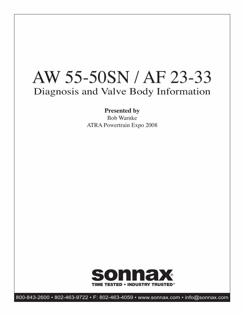
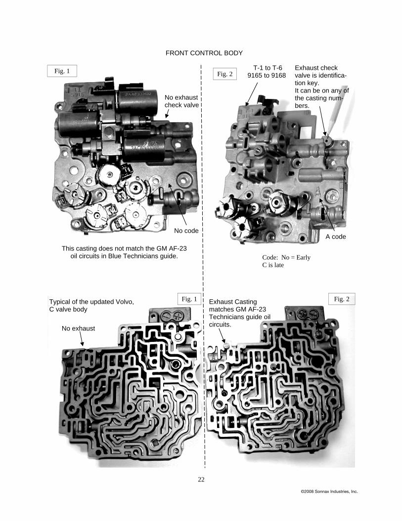
Adapting to the Aisin Warner 55 50SN valve body Some things are less intimidating, if your not the first one to do it. That statement is relative to both the crossing of a frozen lake and a problematic 55 50SN. Because of a heavy snow cover, it cannot be as-sumed the ice is sufficient for support. What you cannot see may result in a sink or swim experience. On the 55 50SN valve body, a clean core is not indicative of the function. This material is a route past the “thin ice” that other travelers have marked. At these flag’s per say, the test or inspection, frequently points to the valve body, as it accounts for the majority of the transmis-sion’s issues. The 55 50/51 SN is installed into a multitude of vehicles and there will be variations to the unit and this data. A similar valve body will bolt to a GM, Volvo, Saturn, Nissan, Saab, Opel or Renault. Failure to test and recognize can create hours of additional effort. Pressure and fill: All the pressure plugs have a 12mm head. Do not mistake the 27mm band anchor (see Figures 1 and 2)for a fill plug or pressure tap. If that anchor is removed, the band will have to be recaptured. Position-ing the band requires removal of the servo, at best and possibly the complete transmission. The turbine sensor hole can be use to improve the fill speed. Low fluid or excessive overfill, can create erratic pressure and poor linear solenoid control, eventually forcing a TCM high pressure strategy.
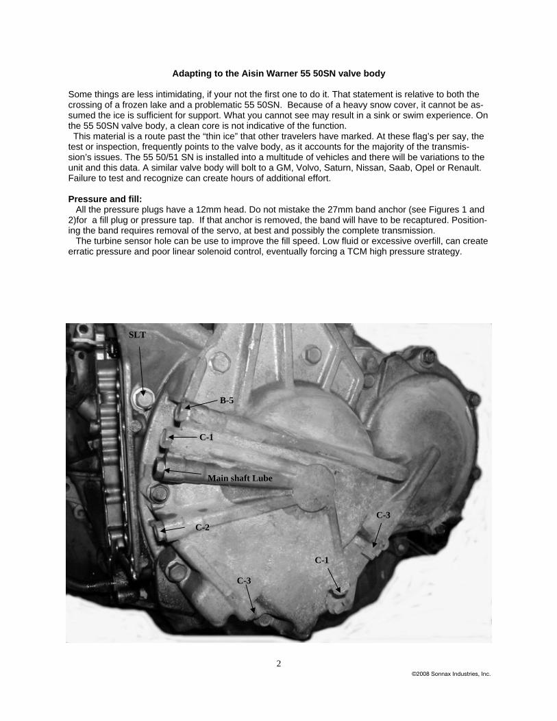
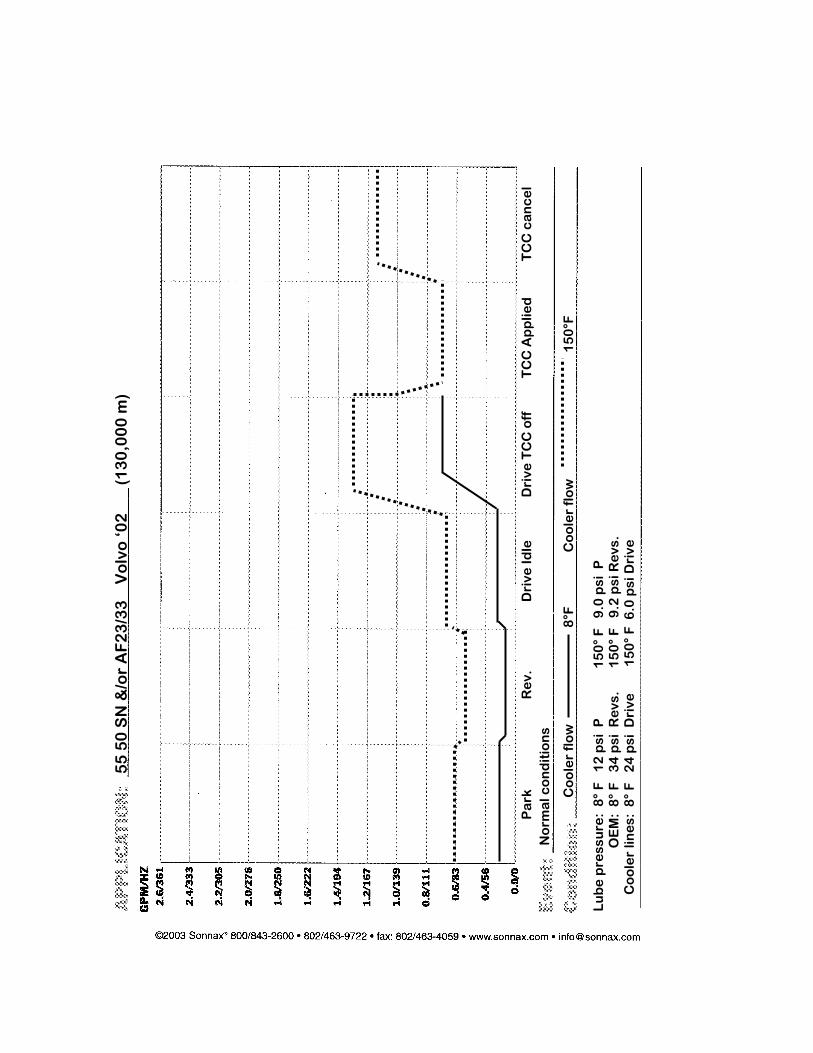
If the transmission is in the vehicle, “test the ice” per say, at the pressure taps relative to these com-plaints: • TCC RPM fluctuation and overheated fluid Check lube pressure. The lube pressure tap is between the secondary regulator valve and the main shaft bushings. Lube pressure will be affected by the fluid viscosity (flow rate) and the bushing to shaft clearance. Sufficient pressure at operating temperature indicates the filter, pump and both primary and secondary regulators are functioning. Normal lube pressure at the port indicated; -10 f. lube pressure can be as high as 30 psi. At 150 f, normal lube will be 5 psi. in Drive and 8 psi. in Reverse. This indi-cates the bushings are in place and can retain some of the source pressure. Lube pressure that starts low and stays at zero psi, would indicate your pump output is low, the regulator valve bore is worn or your bushings are bad. If you are diagnosing a TCC complaint perform a cooler flow test. Normal flow in Drive with TCC re-leased is 1.3 gpm and during TCC apply it drops to .7 gpm. The Saab, cooler element will require an adapter, but most units are easily accessible. Lube pressure and flow on the 55 50SN, is low in comparison to other units. This converter requires multiple valves, along with the rear pump bushing, to control modulated TCC apply (see Figure 3). The converter clutch may remain fully applied at very low speed and high load, which taxes the fluid and lin-ing, creating a break-away slip or RPM fluctuation.
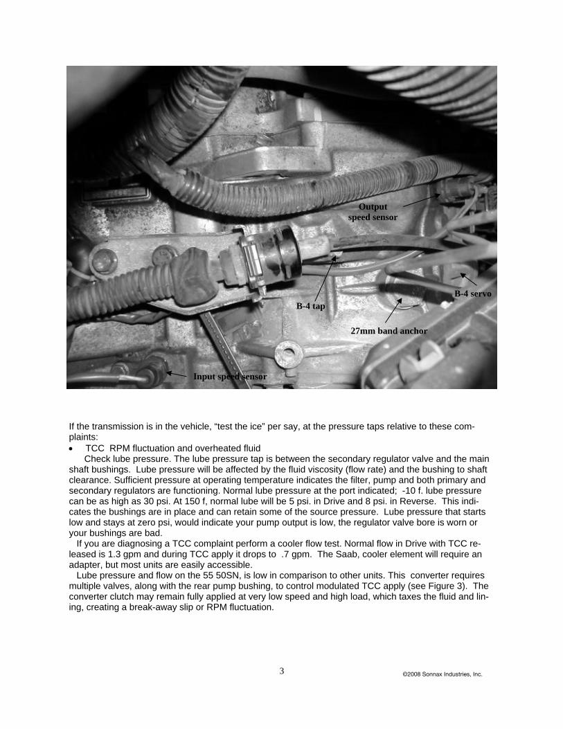
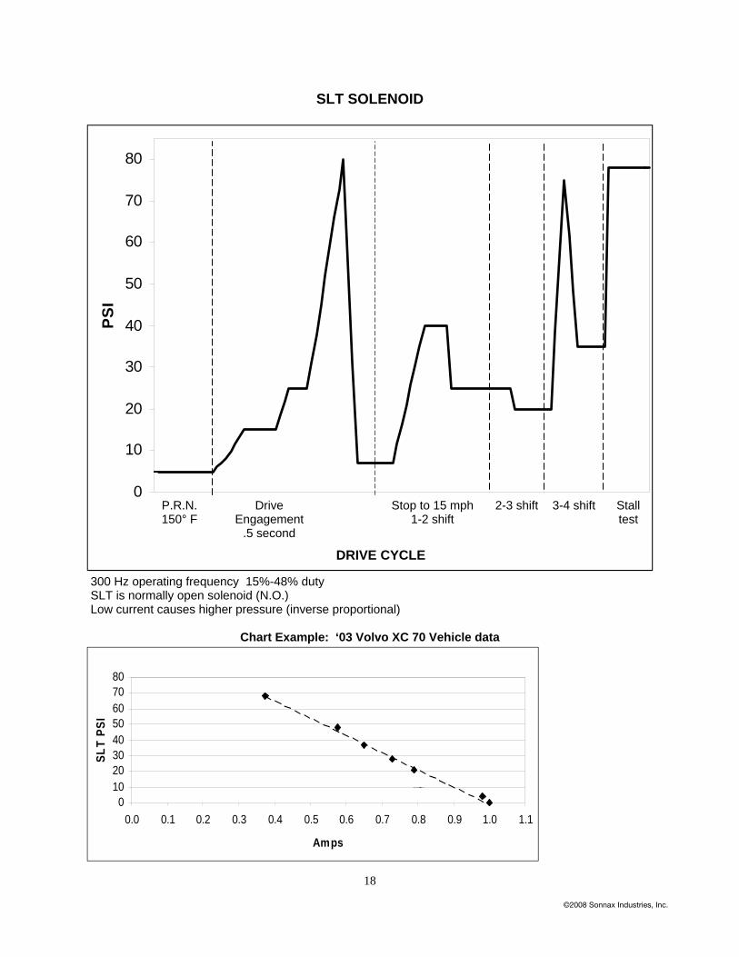
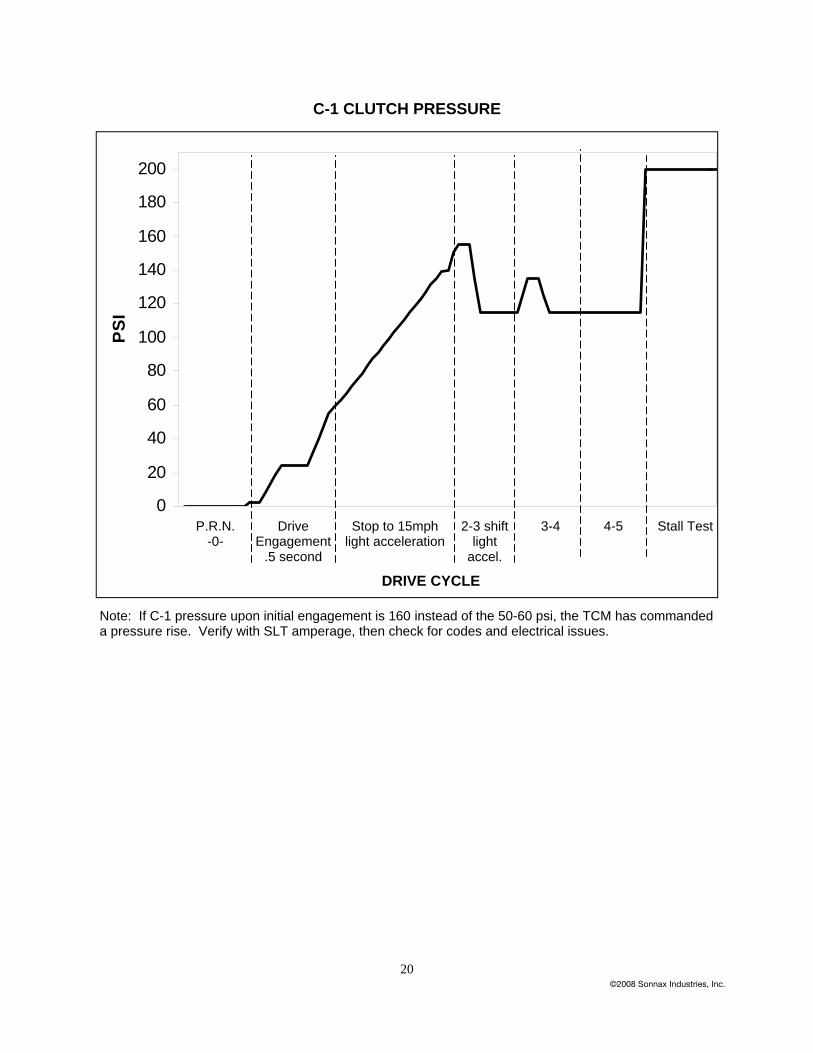
• Delayed engagement and poor/flare shifts Check SLT pressure and C-1 clutch. The C-1 clutch is engaged via pressure rise by SLT solenoid and through a series of modulated valves. The SLT pressure should start at 5 psi. in Drive and increase with throttle and load to 80 psi maximum. SLT will cutback and spike on various shifts, depending on the TCM program. Typical C-1 pressure is -0- in Park. As Drive is selected, it quickly steps to 25 psi., then 50 psi, within half second and remains, until accelerated. C-1 psi. will then follow load, with a maximum near 200 psi. If C-1 pressure upon selecting Drive is immediately 160 psi. and obtains 200 psi. during a shift, the unit may be under a TCM code/ failsafe mode. Engagements at this time are abrupt. Some vehicles ( Volvo specifically) may use a C-1 disengagement via brake signal creating a neutral at idle. Check for a TCM flash to eliminate this condition. • 2-3 shift flare, neutral or harsh Compare the B-4, servo apply pressure, to the C-1 clutch. The B-4 tap is at the top of the case, in line with the linkage bolts. The B-4 circuit has extensive valve body control and includes a tube with o-ring ends that feed the servo. Comparing C-1 to B-4 is an indication of control by the SLS and SLT linear solenoids, a failsafe or leakage condition. Proper B-4 pressure should follow C-1 and never be less than 10 psi.of C-1. (Refer to the C-1 pres-sure testing.) If C-1 psi. is fixed at 160 psi. upon engagement, the 1-2 and 3-4 shift, may be acceptable, but the 2-3 is generally too harsh. A TCM pressure management, code, aerated fluid or bad speed sen-sor, will eliminate the SLT pressure curve and force B-4 to an immediate 200 psi. which results in the harsh 2-3 shift. If the pressure curve of both C-1 and B-4 are parallel, C-1 initial engagement is near 50 psi. and the 2-3 harsh, the vehicle may require a flash update, but perform a key cycle and numerous drive cycles first. Some manufactures ( Volvo) have servo’s and a reflash to improve 2-3, 3-2 drive-ability.
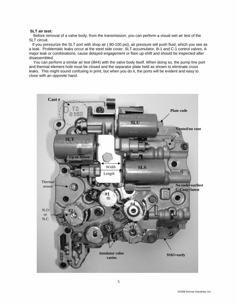
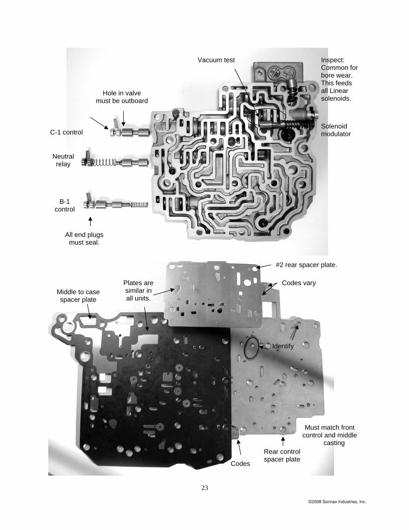
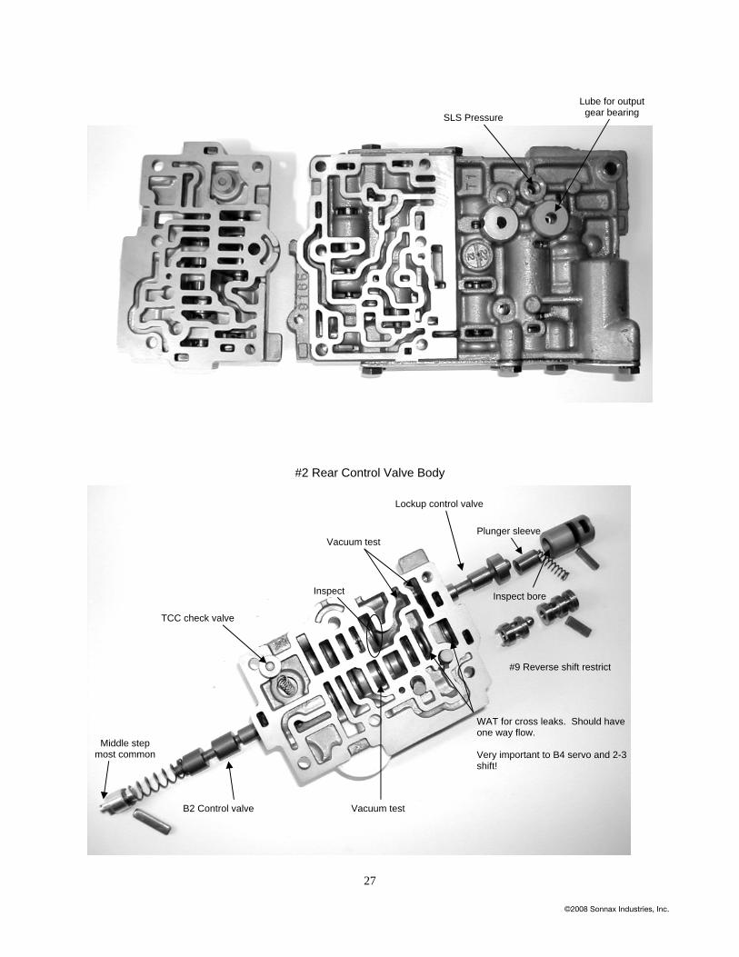
SLT air test: Before removal of a valve body, from the transmission, you can perform a visual wet air test of the SLT circuit. If you pressurize the SLT port with shop air ( 80-100 psi), air pressure will push fluid, which you see as a leak. Problematic leaks occur at the steel side cover, SLT accumulator, B-1 and C-1 control valves. A major leak or combinations, cause delayed engagement or flare up-shift and should be inspected after disassembled. You can perform a similar air test (ill#4) with the valve body itself. When doing so, the pump line port and thermal element hole must be closed and the separator plate held as shown to eliminate cross leaks. This might sound confusing in print, but when you do it, the ports will be evident and easy to close with an opposite hand.
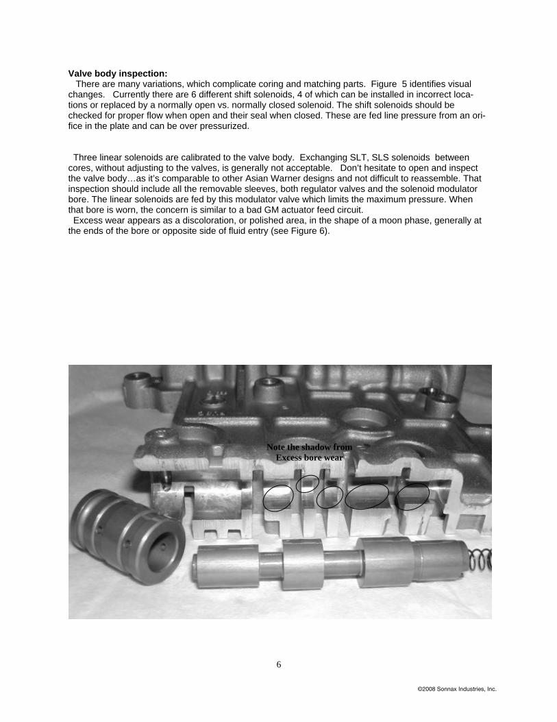
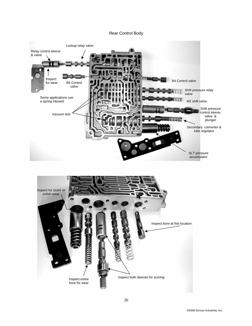
Valve body inspection: There are many variations, which complicate coring and matching parts. Figure 5 identifies visual changes. Currently there are 6 different shift solenoids, 4 of which can be installed in incorrect loca-tions or replaced by a normally open vs. normally closed solenoid. The shift solenoids should be checked for proper flow when open and their seal when closed. These are fed line pressure from an ori-fice in the plate and can be over pressurized. Three linear solenoids are calibrated to the valve body. Exchanging SLT, SLS solenoids between cores, without adjusting to the valves, is generally not acceptable. Don’t hesitate to open and inspect the valve body…as it’s comparable to other Asian Warner designs and not difficult to reassemble. That inspection should include all the removable sleeves, both regulator valves and the solenoid modulator bore. The linear solenoids are fed by this modulator valve which limits the maximum pressure. When that bore is worn, the concern is similar to a bad GM actuator feed circuit. Excess wear appears as a discoloration, or polished area, in the shape of a moon phase, generally at the ends of the bore or opposite side of fluid entry (see Figure 6).
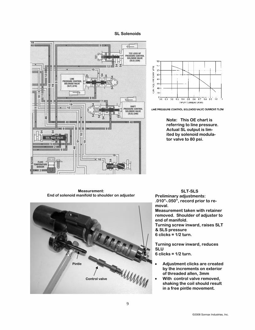
SLT-SLS Preliminary adjustments: .010”-.050”, record prior to re-moval. Measurement taken with retainer removed. Shoulder of adjuster to end of manifold. Turning screw inward, raises SLT & SLS pressure 6 clicks = 1/2 turn. Turning screw inward, reduces SLU 6 clicks = 1/2 turn. • Adjustment clicks are created
by the increments on exterior of threaded allen, 3mm
• With control valve removed, shaking the coil should result in a free pintle movement.
Measurement: End of solenoid manifold to shoulder on adjuster
Note: This OE chart is referring to line pressure. Actual SL output is lim-ited by solenoid modula-tor valve to 80 psi.
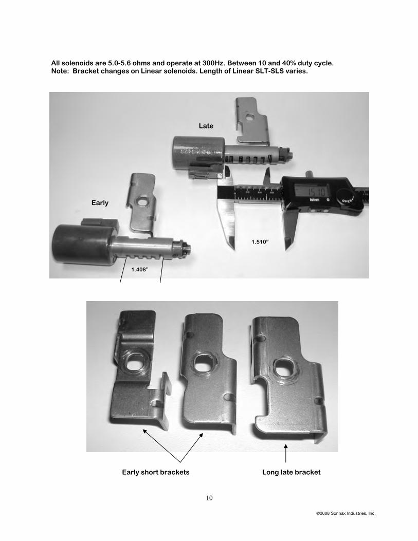
All solenoids are 5.0-5.6 ohms and operate at 300Hz. Between 10 and 40% duty cycle. Note: Bracket changes on Linear solenoids. Length of Linear SLT-SLS varies.
SLU-Remains same Early-Late SLT-Early • Slot for bracket results in solenoid connectors upward. • Bracket is narrow type • Distance bracket slot out ex. 1.408” (short manifold) SLT-Late • Slot for bracket results in connector down • Wider bracket • Long manifold 1.510” • Connector down requires special harness, Volvo update. SLS-Early • Slot for bracket requires connector up. • Narrow bracket • Short manifold 1.408” SLS-Late • Slot for bracket requires connector up. • Wide bracket • Long manifold 1.510” SLS-N.O. • Controls clutch feed pressure at shift pressure control valve. SLU– N.C. • Controls TCC apply • B-4 servo apply • B-2 neutral control Rebuild Comments: G.M. & Saab use different TCM strategy compared to Volvo & Renault. Limp mode is not always 5th gear. Input & output speed sensors are Hall affect.
Be sure to clean them and keep away from stray frequency. Harsh shifts, high line pressure & TCC concerns can be caused by input contamination, also Gear ratios, TCC cycling, 3-5 shift, phantom codes. Add ground straps & distance the sensors from Linear solenoid wiring.
Valve body exchange: G.M. Equinox valve body has been installed successfully onto Volvo. In order to do so, a wiring harness must match SLT Linear connector either positioned up or down. • #2 solenoid is N.O. on G.M. must use Volvo N.C. on #2 • Always resurface castings on all valve body areas. • Seal end plugs for C-1 control, B-4 release, B-1 control
Linear Lock-up Solenoid ( SLU) This solenoid affects:
• 1-2 up-shift. ie; too firm or bumpy • 2-1 downshift. ie; harsh, bump • Light throttle TCC modulation. ie; cycling rpm or cooler flow • Full TCC lockup. Ie; late, bump on coast down release • TCC release on coast; too early, loss of engine brakin Refer to the pressure chart for examples of operation.
SLU service and adjustment at the bench:
• Pre-measure the adjuster, (figure ) remove the threaded adjuster, then the valve from the solenoid.
• Verify the pintle (shaft passing through coil), is free floating by performing a shake test.
• Re-assemble and turn the adjuster to the original position.
Drive-ability and VBT test stand verification:
• The SLU is pulsed during 1-2, 2-1, 2-3, 3-2 shift, also during engagement into Drive or Reverse and TCC apply. Monitoring cooler flow with a Sonnaflow will indi-cate if the SLU is adjusted properly. A quick flow reduction of 50% and then a re-turn, indicates the SLU is reacting to TCC valves. For example, 1.0 gpm. in Park, then upon Drive engagement, a sharp drop to .06, and a quick return, identifies the correct action.
• If you have harsh up/down shifts and you do not see a cooler flow toggle, the SLU is not adjusted or working properly.
• The correct adjustment on SLU will increase cooler flow. Improper adjustment will reduce cooler flow, substantially.
SLU adjustment in the vehicle:
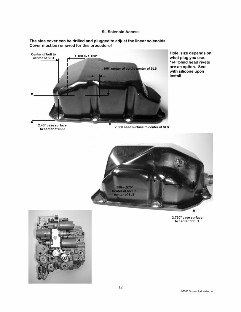
• The solenoid can be adjusted if a pass-through hole has been located in the cover during bench rebuild. ( figure ). The SLU access will be at the top, left corner. A 3 mm Allen wrench, will pass approximately 1.60” or 40.9 mm. through the cover, when it’s inserted into the adjuster. You should be able to feel the Allen engage-ment. As you turn the Allen wrench you will feel the retainer click over the index.
Always count your rotations, in clockwise (CW) or counterclockwise (CCW), so you know where you start /stop.
CW/ In : Reduces SLU output. Resulting in: hard 1-2, 2-1 shifts and firmer/later TCC CCW/ Out: Increases SLU output. Resulting in softer shifts and earlier TCC
Road test: • If your TCC control, 1-2 and 2-1 are good, cooler flow drops properly as noted above,
leave the adjustment as is. If not, adjust accordingly. • Slight bump on 2-1 down-shift… and/or TCC rpm fluctuates at 30-40 MPH during
modulated apply….and/or excess TCC slip at full lockup…and/or Sonnaflow sensor indicates TCC control valve is continually toggling on-off. If so… turn adjuster screw in/clockwise 1.0 turn.
• Harsh 2-1 downshift….and/or heavy TCC RPM fluctuation at 30-40 mph…and/or late and firm full TCC apply. If so…turn adjuster in/clockwise 1.5 to 2.0 turns.
• TCC will apply not modulate slip RPM at 30-40 mph. Beyond 40 mph, TCC apply is short and harsh…. and/or a harsh TCC release on coast and/or 1-2 shift is too harsh. The adjuster is too far inward, back it out/ counter clockwise as required 1.5 to 2.5 turns.
• Low cooler flow when in lockup. No TCC flow drop upon engagement or shifting. Ad-juster may be too far out/CCW.
Note: The spring between the adjuster and the valve tends to have some memory or coil wrap up. If you over-compensate in one direction, it may require more of an opposite direc-tion to restore!
During road test, you will need a temporary plug in the access holes.
If you can feel the adjuster turn out against the retainer, STOP… or you can force the retainer off. If you have adjusted to this point, you are beyond resolving a problem with a solenoid adjustment. Generally 1-2 turns in/ out is all that is needed.
Line Pressure Solenoid ( SLT) This solenoid affects:
• Reverse engagement. ie; too firm, or delay • Forward engagement. Ie; delay forward • Upshift/downshift quality. ie: harsh upshifts, coast down clunk • 2-3 upshift. ie: long flare, or tail bump • SLT pressure tap. Pressure too low, and slow response.
Refer to the pressure chart for examples
Solenoid service and adjustment at the bench: The service procedure is the same as the SLU and SLS. Measure before and return the adjustment after cleaning. Drive-ability and VBT test stand verification: The SLT is the line rise control solenoid. It sets the position of the C-1 clutch control for for-ward engagement. It positions the B1 valve for second clutch feed on 1-2, 2-1 shifts. It boosts secondary regulator valve, converter and lube pressure and controls 2-3 shift at the B-4 control valve. It is a very critical adjustment! Insure the end plugs at these valves are sealed and secondary regulator bore is not worn or this pressure is either lower, or too high. High SLT and harsh Reverse can be caused by bore wear at the secondary regulator bore, near the spring spool. This solenoid operates at 300 Hz, and has control between 15 to 45 % duty. Refer to charts and review SLU. SLT adjustments in the vehicle: This access hole is on the right side of the cover, easiest to adjust of all three. You must monitor this pressure with a 0-100 psi gauge, to set accurately. OE correct SLT, is approxi-mately 5-6 psi. in Drive range. Maximum obtained SLT is 78 psi. Turning the SLT screw inward/clockwise, increases the SLT pressure. High SLT pressure causes: ( CCW / out, reduces SLT) Example; 20 psi. of SLT in Drive Results in long 2-3 shift, or an overlap / bind up on 2-3. Also a 3-2 coast down bump. For-ward engagements become harsh. TCC apply ramp becomes short and there can be a loss of TCC modulation slip at lower speed. Lube pressure and cooler flow become less at excessive SLT pressure. Low SLT pressure causes: ( CW / in, increases SLT) Example: -0- SLT in drive. Causes a Neutral to Drive delay, often with a bang engagement. Long shifts and lower than desired cooler flow. Note: Increasing SLT , generally will not eliminate a 2-3 flare. Check servo design and travel. Then test B4 pressure tap, It should be parallel to C-1.
Shift Pressure Control Solenoid (SLS) This solenoid affects:
• Reverse engagement. • Upshift and downshifts. • Does not affect forward engagement.
This solenoid pressure only reacts on the shift pressure control plunger to adjust clutch pres-sure. It is pulsed to control the feed rate of the clutch dependant on engine load.
Refer to the application chart. The service procedure is the same as the SLU, and SLT above. Drive-ability and VBT test stand verification: The valve body has an SLS access on the back-side, with a 10mm hex nut. It is not acces-sible in the vehicle. On the VBT the solenoid is operated at 300 Hz. To duplicate the correct on-car operation, this solenoid would have the duty % lowered during each up/ down shift. Pressure ranges from –0- to 78 psi. Insure the end plate on the rear control body is flat and the bore of the outer sleeve is not worn. Generally these do not wear in excess. SLS adjustments in the vehicle: The access hole will be located on the left side of the cover, lower than the SLU and in the bolt radius of the cover. Turning the SLS screw inward/clockwise, increases the SLS pressure. High SLS pressure causes: ( CCW/ out, reduces SLS pressure) Harsh reverse. 1-2 shift harsh. 2-3 harsh with an end bump. Loss of TCC apply. Elevated C-1 clutch pressure. 3-2 maneuver flare/ bang . Note: Some of the 3-2 bang complaints are caused by a non-compatible valve body. Some of these 3-2 flare, can be reduced with SLS adjustments. Low SLS pressure causes: ( CW/ in, increases SLS) Soft upshifts. Low speed 2-3 flare Slight RPM flare on 3-4, 4-5 shifts. Note: SLS does not affect forward engagements.
17
0.0
0.10.2
0.3
0.40.5
0.60.7
0.8
0.91.0
1.1
AM
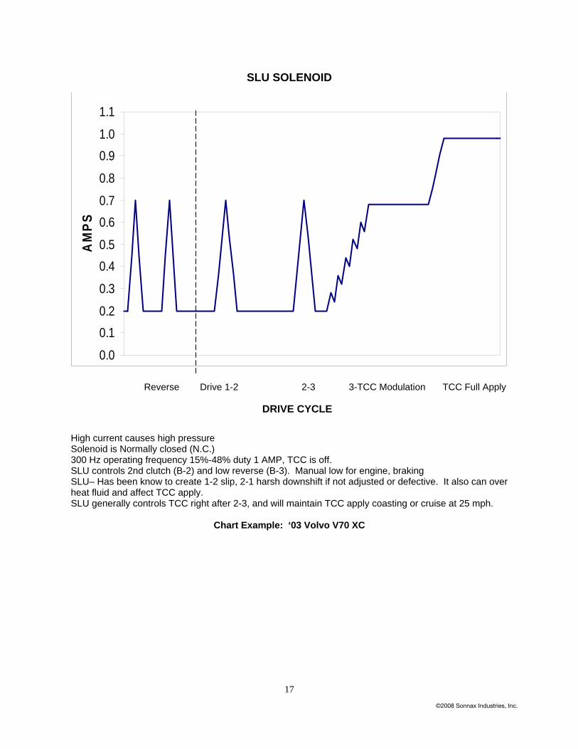
PSSLU SOLENOID
Reverse Drive 1-2 2-3 3-TCC Modulation TCC Full Apply
High current causes high pressure Solenoid is Normally closed (N.C.) 300 Hz operating frequency 15%-48% duty 1 AMP, TCC is off. SLU controls 2nd clutch (B-2) and low reverse (B-3). Manual low for engine, braking SLU– Has been know to create 1-2 slip, 2-1 harsh downshift if not adjusted or defective. It also can over heat fluid and affect TCC apply. SLU generally controls TCC right after 2-3, and will maintain TCC apply coasting or cruise at 25 mph.
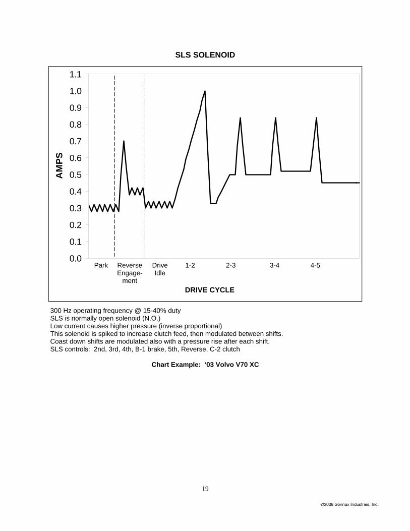
300 Hz operating frequency @ 15-40% duty SLS is normally open solenoid (N.O.) Low current causes higher pressure (inverse proportional) This solenoid is spiked to increase clutch feed, then modulated between shifts. Coast down shifts are modulated also with a pressure rise after each shift. SLS controls: 2nd, 3rd, 4th, B-1 brake, 5th, Reverse, C-2 clutch
Note: If C-1 pressure upon initial engagement is 160 instead of the 50-60 psi, the TCM has commanded a pressure rise. Verify with SLT amperage, then check for codes and electrical issues.
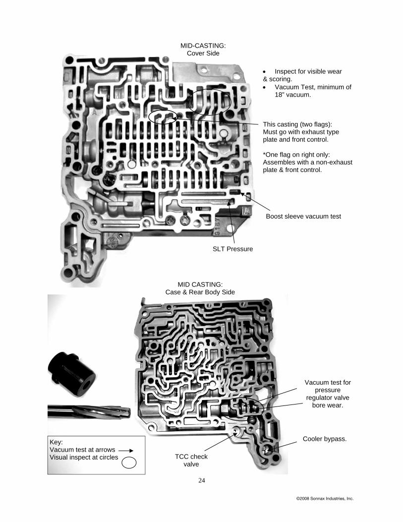
• Inspect for visible wear & scoring. • Vacuum Test, minimum of
18” vacuum.
Boost sleeve vacuum test
This casting (two flags): Must go with exhaust type plate and front control. *One flag on right only: Assembles with a non-exhaust plate & front control.
Key: Vacuum test at arrows Visual inspect at circles
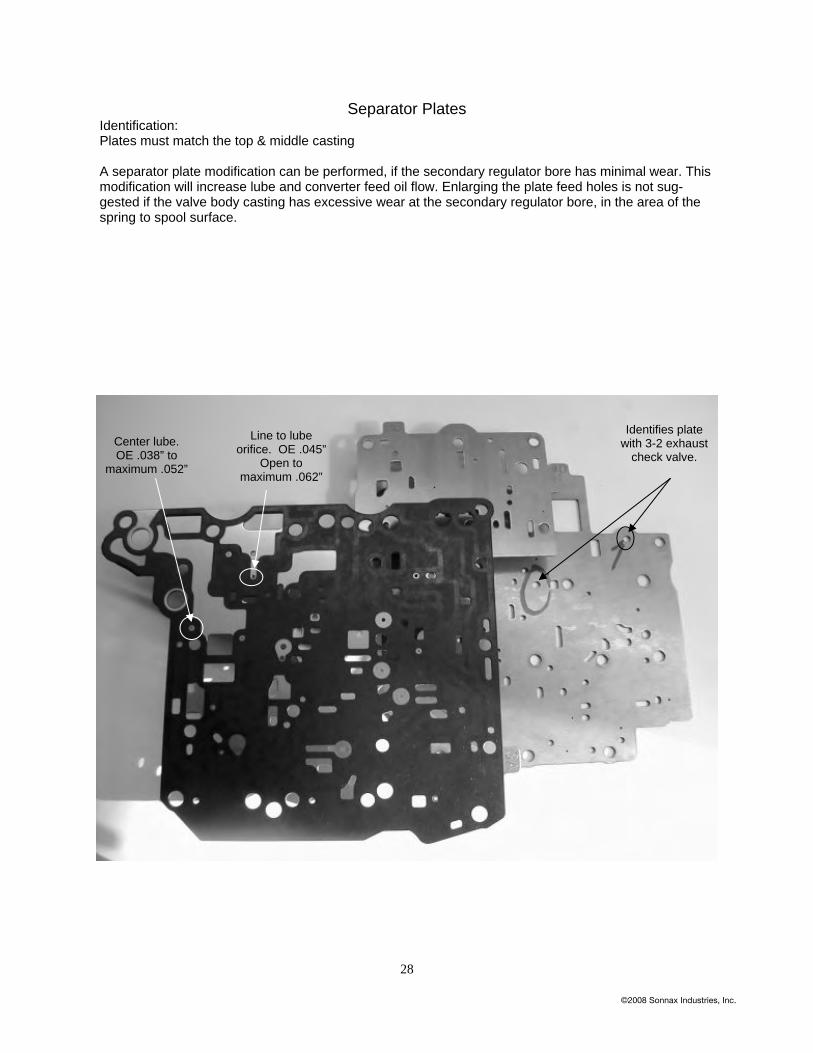
Separator Plates Identification: Plates must match the top & middle casting A separator plate modification can be performed, if the secondary regulator bore has minimal wear. This modification will increase lube and converter feed oil flow. Enlarging the plate feed holes is not sug-gested if the valve body casting has excessive wear at the secondary regulator bore, in the area of the spring to spool surface.
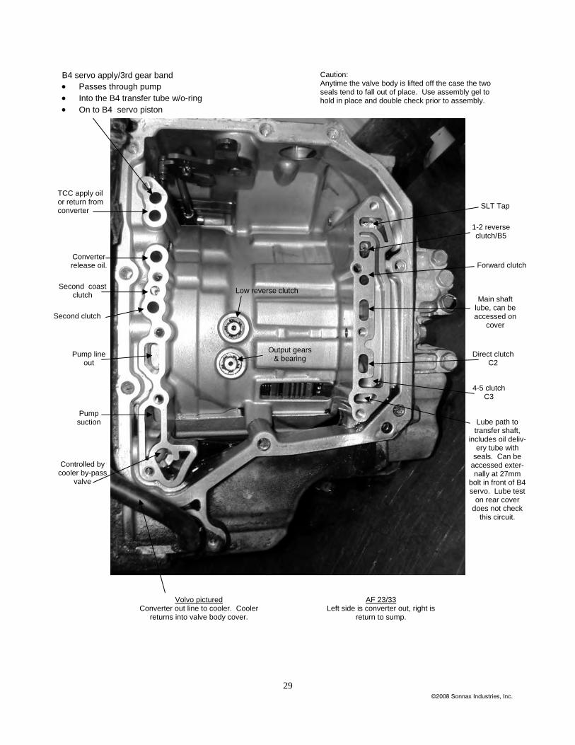
B4 servo apply/3rd gear band • Passes through pump • Into the B4 transfer tube w/o-ring • On to B4 servo piston
Caution: Anytime the valve body is lifted off the case the two seals tend to fall out of place. Use assembly gel to hold in place and double check prior to assembly.
TCC apply oil or return from converter
Converter release oil.
Second coast clutch
Second clutch
Pump line out
Pump suction
Controlled by cooler by-pass
valve
Low reverse clutch
Output gears & bearing
SLT Tap
1-2 reverse clutch/B5
Forward clutch
Main shaft lube, can be accessed on
cover
Direct clutch C2
4-5 clutch C3
Lube path to transfer shaft,
includes oil deliv-ery tube with
seals. Can be accessed exter-nally at 27mm
bolt in front of B4 servo. Lube test
on rear cover does not check
this circuit.
Volvo pictured Converter out line to cooler. Cooler


![AW55-50SN Vacuum Sheet[1]](https://static.documents.pub/doc/80x56/5434002f219acd5f1a8b51fa/aw55-50sn-vacuum-sheet1.jpg)


