68
AWS-8129H Industrial Workstation with 12.1" Flat Panel Display User's Manual
AWS-8129H Industrial Workstation with 12.1" Flat Panel Display
User's Manual
Copyright Notice
This document is copyrighted September 2006, by Advantech Co., Ltd. All rights are reserved. Advantech Co., Ltd. reserves the right to make improvements to the products described in this manual at any time without notice.
No part of this manual may be reproduced, copied, translated, or transmitted in any form or by any means without the prior written permission of Advantech Co., Ltd. Information provided in this manual is intended to be accurate and reliable. However, Advantech Co., Ltd. assumes no responsibility for its use; nor for any infringements of the rights of third parties which may result from its use.
Acknowledgments
AWS-8129H2-XAE, AWS-8129H2-RAE, AWS-8129H1-XAE and AWS-8129H1-RAE, are all trademarks of Advantech Co., Ltd. IBM and PC are trademarks of International Business Machines Corporation. MS-DOS is a trademark of Microsoft Corporation. All other brand and product names mentioned herein are trademarks or registered trademarks of their respective holders.
Part No. 2003812900 1st Edition Printed in Taiwan Sep. 2006
ii
FCC Class A
This equipment has been tested and found to comply with the limits for a Class A digital device, pursuant to Part 15 of the FCC Rules. These limits are designed to provide reasonable protection against harmful interference when the equipment is operated in a commer- cial environment. This equipment generates, uses and can radiate radio frequency energy. If not installed and used in accordance with this user's manual, it may cause harmful interference to radio communications. Operation of this equipment in a residential area is likely to cause harmful interference, in which case the user will be required to correct the interference at his own expense.
iii
Packing List
Before you set up the AWS-8129H workstation, make sure that the following materials have been included with the package, and that this manual is in good condition. If anything is missing or damaged, contact your dealer immediately:
One AWS-8129H industrial workstation with 12.1" flat panel display
One accessory box, including: - One HMI products drivers and utilities CD-ROM - One utility diskette for function key programming - AWS-8129H User's Manual - Cable to link front PS/2 connector to CPU card - Flat gray cable for 3.5" HDD and slim CD-ROM - A Y-cable for PS/2 keyboard and mouse - RS-232 cable to link touchscreen to CPU card (only -T
models) - Screw bag with screws
If any of these items are missing or damaged, contact your distributor or sales representative immediately.
iv

Additional Information And Assistance
1. Visit the Advantech web sites at www.advantech.com or www.advantech.com.tw where you can find the latest information about the product.
2. Contact your distributor, sales representative, or Advantech's customer service center for technical support if you need additional assistance. Please have the following information ready before you call:
• Product name and serial number • Description of your peripheral attachments • Description of your software (operating system, version,
application software, etc.) • A complete description of the problem • The exact wording of any error messages
v

Safety Instructions
1. Read these safety instructions carefully. 2. Keep this User's Manual for later reference. 3. Disconnect this equipment from any AC outlet before cleaning. Use a damp cloth.
Do not use liquid or spray detergents for cleaning. 4. For plug-in equipment, the power outlet socket must be located near the
equipment and must be easily accessible. 5. Keep this equipment away from humidity. 6. Put this equipment on a reliable surface during installation. Dropping it or letting
it fall may cause damage. 7. The openings on the enclosure are for air convection. Protect the equipment
from overheating. DO NOT COVER THE OPENINGS. 8. Make sure the voltage of the power source is correct before connecting the
equipment to the power outlet. 9. Position the power cord so that people cannot step on it. Do not place anything
over the power cord. 10. All cautions and warnings on the equipment should be noted. 11. If the equipment is not used for a long time, disconnect it from the power source to
avoid damage by transient overvoltage. 12. Never pour any liquid into an opening. This may cause fire or electrical shock. 13. Never open the equipment. For safety reasons, the equipment should be opened only
by qualified service personnel. 14. If one of the following situations arises, get the equipment checked by service
personnel: a. The power cord or plug is damaged. b. Liquid has penetrated into the equipment. c. The equipment has been exposed to moisture. d. The equipment does not work well, or you cannot get it to work according to the
user's manual. e. The equipment has been dropped and damaged. f. The equipment has obvious signs of breakage.
15. DO NOT LEAVE THIS EQUIPMENT IN AN UNCONTROLLED ENVIRONMENT WHERE THE STORAGE TEMPERATURE IS BELOW -20° C (-4° F) OR ABOVE 60° C (140° F). THIS MAY DAMAGE THE EQUIPMENT.
The sound pressure level at the operator's position according to IEC 704-1:1982 is no more than 70dB(A).
DISCLAIMER: This set of instructions is given according to IEC 704-1. Advantech disclaims all responsibility for the accuracy of any statements contained herein.
vi

Wichtige Sicherheishinweise
1. Bitte lesen sie Sich diese Hinweise sorgf‰ltig durch. 2. Heben Sie diese Anleitung f¸r den sp‰teren Gebrauch auf. 3. Vor jedem Reinigen ist das Ger‰t vom Stromnetz zu trennen.
Verwenden Sie Keine Fl¸ssig-oder Aerosolreiniger. Am besten dient ein angefeuchtetes Tuch zur Reinigung.
4. Die NetzanschluBsteckdose soll nahe dem Ger‰t angebracht und leicht zug‰nglich sein.
5. Das Ger‰t ist vor Feuchtigkeit zu sch¸tzen. 6. Bei der Aufstellung des Ger‰tes ist auf sicheren Stand zu achten. Ein
Kippen oder Fallen kˆnnte Verletzungen hervorrufen. 7. Die Bel¸ftungsˆffnungen dienen zur Luftzirkulation die das Ger‰t vor
¸berhitzung sch¸tzt. Sorgen Sie daf¸r, daB diese ÷ffnungen nicht abgedeckt werden.
8. Beachten Sie beim. AnschluB an das Stromnetz die AnschluBwerte. 9. Verlegen Sie die NetzanschluBleitung so, daB niemand dar¸ber fallen kann.
Es sollte auch nichts auf der Leitung abgestellt werden. 10. Alle Hinweise und Warnungen die sich am Ger‰ten befinden sind zu
beachten. 11. Wird das Ger‰t ¸ber einen l‰ngeren Zeitraum nicht benutzt, sollten Sie es
vom Stromnetz trennen. Somit wird im Falle einer ‹berspannung eine Besch‰digung vermieden.
12. Durch die L¸ftungsˆffnungen d¸rfen niemals Gegenst‰nde oder Fl¸s- sigkeiten in das Ger‰t gelangen. Dies kˆnnte einen Brand bzw. elek- trischen Schlag auslˆsen.
13. ÷ffnen Sie niemals das Ger‰t. Das Ger‰t darf aus Gr¸nden der elektrischen Sicherheit nur von authorisiertem Servicepersonal geˆffnet werden.
14. Wenn folgende Situationen auftreten ist das Ger‰t vom Stromnetz zu trennen und von einer qualifizierten Servicestelle zu ¸berpr¸fen: a - Netzkabel oder Netzstecker sind besch‰digt. b - Fl¸ssigkeit ist in das Ger‰t eingedrungen. c - Das Ger‰t war Feuchtigkeit ausgesetzt. d - Wenn das Ger‰t nicht der Bedienungsanleitung entsprechend funktioni
ert oder Sie mit Hilfe dieser Anleitung keine Verbesserung erzielen. e - Das Ger‰t ist gefallen und/oder das Geh‰use ist besch‰digt. f - Wenn das Ger‰t deutliche Anzeichen eines Defektes aufweist.
Der arbeitsplatzbezogene Schalldruckpegel nach DIN 45 635 Teil 1000 betr‰gt 70dB(A) oder weiger.
DISCLAIMER: This set of instructions is given according to IEC704-1. Advantech disclaims all responsibility for the accuracy of any statements contained herein.
vii
Contents Chapter 1 Introduction ........................................................ 1
1.1 Description .............................................................................. 2 1.2 Specifications .......................................................................... 4 1.3 LCD display ............................................................................. 6 1.4 Dimensions .............................................................................. 7 1.5 Complete Functionality ......................................................... 8 1.6 Front Accessible CD-ROM ............................................... 9 1.7 Front Control Panel ............................................................ 1 0
Chapter 2 System Setup ................................................... 11 2.1 General ................................................................................. 1 2 2.2 Opening The Top Panel and Rear Panel ......................... 1 3 2.3 Adding Cards ....................................................................... 1 5 2.4 Installing Optional Drives ................................................ 1 6 2.5 Connecting Cables ............................................................. 2 0 2.6 Connecting External Keyboard and Mouse .............. 2 1 2.7 Panel Mounting ................................................................... 2 2 2.8 Rack Mounting ................................................................... 2 3
Chapter 3 KBT-2002 Macro Key Programming ............. 25 3.1 Introduction .......................................................................... 26 3.2 Macro Key Components ..................................................... 26 3.3 How to use Main.exe to edit Macro Key ............................ 26 3.4 Examples .............................................................................. 27
viii

Chapter 4 Maintenance .................................................... 33
4.1 Detaching The Backplane And Bracket ................. 34 4.2 Power Supply ........................................................................ 3 5 4.3 LCD Maintenance .............................................................. 36 4.4 Keyboard Translator ........................................................... 3 8 4.5 LED Board ........................................................................... 41 4.6 Touchscreen Controller ..................................................... 41
Appendix A Power Supply Specifications ...................... 43 A.1 250 Watt Power Supply ....................................................... 4 4
Appendix B Touchscreen Driver Installation ................. 49 B.1 Introduction ................................................................ 50
B.1.1 Installation for Windows 98/2000............................. 51 B.1.2 Installation for Windows XP ........................................ 54
Appendix C Touchpad Driver & Utility Installation ....... 57
ix

Figures
Figure 1-1: Dimensions ................................................................................................. 7 Figure 1-2: Complete functionality ........................................................................... 8 Figure 1-3: Front accessible CD-ROM ........................................................................... 9 Figure 1-4: Front control panel ..................................................................................... 10 Figure 2-1: Opening the top panel ................................................................................ 13 Figure 2-2: Opening the rear panel .............................................................................. 14 Figure 2-3: Installing add-on cards ............................................................................... 15 Figure 2-4: Installing optional disk drives - overall view ........................................... 16 Figure 2-5: Installing an FDD ....................................................................................... 17 Figure 2-6: Installing an HDD ...................................................................................... 18 Figure 2-7: Installing a CD-ROM ................................................................................. 19 Figure 2-8: Connecting cables ....................................................................................... 20 Figure 2-9: Connecting keyboard/mouse from front panel ....................................... 21 Figure 2-10: Connecting keyboard from back chassis ................................................ 21 Figure 2-11: Panel mounting ......................................................................................... 22 Figure 2-12: Rack mounting .......................................................................................... 23 Figure 3-1: The Macro Editor screen ............................................................................ 29 Figure 3-2: Macro examples .......................................................................................... 30 Figure 4-1: Detaching the backplane and bracket ...................................................... 32 Figure 4-2: Installing the power supply ....................................................................... 33 Figure 4-3: Installing the LCD backlight .................................................................... 35 Figure 4-4: Keyboard translator input/output (basic schematic) .............................. 37 Figure 4-5: Keyboard translator input/output (detailed schematic) ......................... 38
Tables
Table 1-1: LCD Display ................................................................................................................... 6
x
1
Introduction
• Description
• Specifications • Dimensions • Complete functionality
• Front accessible CD-ROM
• Front control panel

1.1 Description
The AWS-8129H series workstations take advantage of modern flat-panel displays for minimum size. The AWS-8129H offers two types of passive backplane, 4 PCI / 4 ISA / 1 CPU (AWS-8129H1-XAE/-RAE) and 8 ISA (AWS-8129H2-XAE/-RAE) slots, 250 watt power supply, data-entry/function-key keypads, a slim floppy drive, and two spaces for a hard drive and a slim CD-ROM. A high-quality steel frame gives security and environmental protection that meets the toughest industrial standards.
Versatile backplane supply
The backplanes were formed by four-layer PCBs with ground and power planes for reduced noise and lower power-supply impedance. They have LED power indicators for +5 V, +12 V, -5 V and -12 V. The AWS-8129H1-XAE/-RAE contains four PCI-compatible slots, four PC/AT-compatible (ISA-bus) slots and one dedicated slot for the CPU card.
Sealed-membrane tactile-response keypad
You can enter data with the workstation’s two convenient sealed-membrane keypads, one with 60 data keys, the other with 20 function keys. An external keyboard can be attached through a connector on the front panel. A built-in keyboard interface module merges keyboard and keypad signals into a single output signal that acts like a standard IBM AT keyboard. No special software or I/O ports are needed. (Refer to section 4.4 for a detailed description.)
2 AWS-8129H User's Manual
Note: To use the keyboard and keypad
simultaneously, you must first connect the keyboard connector on the backplane to the keyboard connector on the CPU card, and then connect the external keyboard jack to another keyboard jack located next to the power supply. If you connect the keyboard to the 5-pin DIN connector on the CPU card, neither the keyboard nor the keypad will work. The keyboard must be connected to the jack behind the front door.
Accessible and secure control panel
We have put all the workstation's controls at the front of the unit for easy access. A door protects the controls from damage. External controls are: power ON/OFF and reset switches, slim floppy disk drive, slim CD-ROM drive and PS/2 port. Two LEDs indicate power ON and HDD status. There is a control to adjust the brightness or contrast of the LCD display.
Chapter 1 Introduction 3

1.2 Specifications
General
• Front panel: Aluminum, meets NEMA 4 or IP 65
• Disk drive housing: Supports one slim 3.5" FDD, one 3.5" HDD and one slim CD-ROM
Note: For AWS-8129H2-XAE and AWS-8129H2-RAE, we recommend PCA-6751, 6752 and 6770 series CPU card, whose signals are 3.3 V.
• Cooling system: One 49 CFM fan on rear panel
• Membrane keypads: One with 60 data entry keys, one with 10 function keys and 10 programmable macro function keys
• Keyboard connector: 6-pin PS/2 connector with dust-proof door on front panel
• Indicators: LEDs for Power On/Off and HDD activity
• Linear VR adjustment: Brightness and on/off control
• Operating temperature: 0 ~ 50° C (32 ~ 122° F)
• Relative humidity: 5 ~ 85% @ 50° C, non-condensing
• CE compliant
• Dimensions (W x H x D): 482 x 266 x 307 mm (19.0" x 10.5" x 12.1")
• Weight: 15 kg (33 lb)
Touchscreen (optional)
• Type: Analog resistive
• Resolution: Continuous 4 AWS-8129H User's Manual

• Light transmission: 75%
• Controller: USB interface
• Power consumption: +5 V @ 200 mA
• Software driver: Supports Windows 98/2000/XP
Passive backplane
• PCA-6109P4 (AWS-8129H1-XAE/-RAE): 4 ISA, 4 PCI, 1 CPU slot
• PCA-6109 (AWS-8129H2-XAE/-RAE): 9 ISA slot
Power supply options
AC input 250 W (standard offer)
• Input: 85 ~ 130 VAC or 180 ~ 260 VAC, switchable
• Output: +5 V @ 25 A; +12 V @ 9 A; -5 V @ 0.5 A; -12 V @ 2.0 A
• MTBF: 100,000 hours
• Safety: UL/CSA/TUV
-48 VDC input 310 W (ODM option)
• Input: -38 ~ -58 VDC
• Output: +5 V @ 25 A; +12 V @ 10 A; -5 V @ 1 A; -12 V @ 5 A
• MTBF: 100,000 hours
24 VDC input 250 W (ODM option)
• Input: 19 ~ 32 VDC
• Output: +5 V @ 25 A; +12 V @ 10 A; -5 V @ 1 A; -12 V @ 1 A
• MTBF: 100,000 hours
Chapter 1 Introduction 5

1.3 LCD display
Model AWS-8129H
Display type 12.1" TFT color
Max. resolution 800 x 600
Max. colors 256 K colors
Dot siz e (mm) 0.3075 x 0.3075
Luminance (cd/m2) 200
Viewing angle 90°
Temperature 0 ~ 50° C Brightness & VR controller on/off
LCD MTBF 50,000 hours
Backlight MTBF 20,000 hours
Table 1-1: LCD Display 6 AWS-8129H User's Manual

1.4 Dimensions
Before you rack mount or panel mount the AWS-8129H series workstation, use the following diagram to verify that the mounting screws correspond with the holes in your panel/rack.
Figure 1-1: Dimensions Chapter 1 Introduction 7
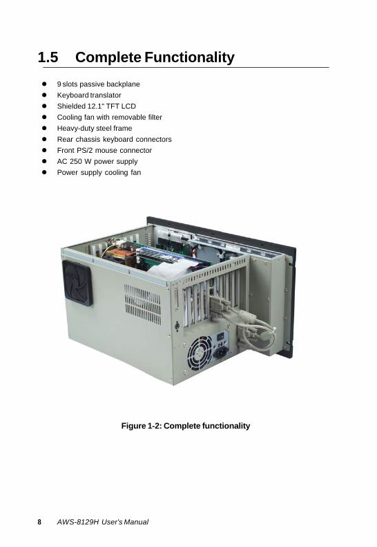
1.5 Complete Functionality
9 slots passive backplane Keyboard translator Shielded 12.1" TFT LCD Cooling fan with removable filter Heavy-duty steel frame Rear chassis keyboard connectors Front PS/2 mouse connector AC 250 W power supply Power supply cooling fan
Figure 1-2: Complete functionality
8 AWS-8129H User's Manual

1.6 Front Accessible CD-ROM
Figure 1-3: Front accessible CD-ROM
Chapter 1 Introduction 9
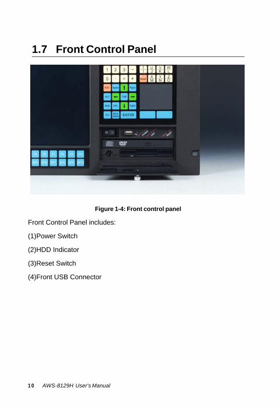
1.7 Front Control Panel
Figure 1-4: Front control panel Front Control Panel includes: (1)Power Switch (2)HDD Indicator (3)Reset Switch (4)Front USB Connector 1 0 AWS-8129H User's Manual
2
System Setup
• General • Opening the top panel and rear panel • Adding cards • Installing optional drives • Connecting cables • Connecting external keyboard and mouse • Panel mounting • Rack mounting
2.1 General
Your AWS-8129H is easy to use. All you have to do is remove its cover, install your CPU card, display adapter card, an optional hard disk drive, and whatever additional I/O cards that your application requires, and you are ready to mount your workstation into a 19-inch rack or panel.
Warning! Do not begin your installation until you are sure
there is no power flowing within the AWS-8129H. It must be switched off and unplugged. Every time you access the inside of the AWS-8129H, you should switch it off and unplug it.
12 AWS-8129H User's Manual

2.2 Opening The Top Panel And Rear
Panel
Remove the eight screws from the top panel and then open the top cover. (See Fig. 2-1.) After removing the top cover, you can detach the six screws from the rear panel and open the rear panel. (See Fig. 2-2.)
Figure 2-1: Opening the top panel
Chapter 2 System Setup 13
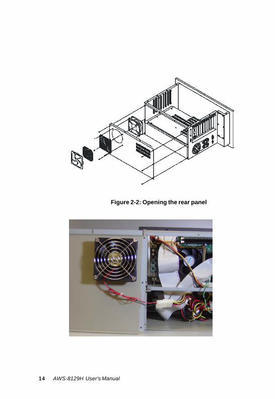
Figure 2-2: Opening the rear panel 14 AWS-8129H User's Manual

2.3 Adding Cards
The PCI passive backplane accepts both PCI-bus and ISA-bus CPU and I/O cards. We recommend all-in-one cards. They are durable, and save valuable slot space by bundling a CPU card with hard disk and floppy disk controllers, as well as serial and parallel ports.
Open the top panel (see Section 2.2) and then slowly slide the card in and carefully press it into the backplane socket. Secure it with a screw to the top mounting bar. (See Fig. 2-3). Connect the wires. Install additional cards as needed. When you have finished, reattach the cover.
Figure 2-3: Installing add-on cards
Chapter 2 System Setup 15
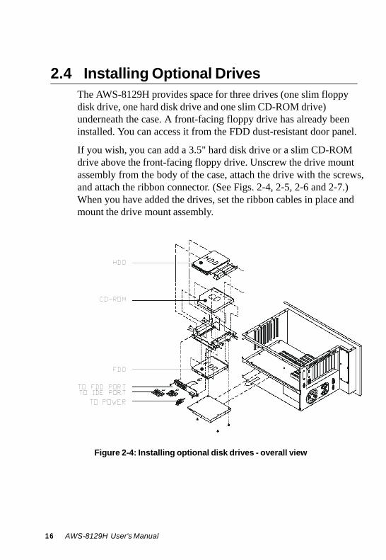
2.4 Installing Optional Drives
The AWS-8129H provides space for three drives (one slim floppy disk drive, one hard disk drive and one slim CD-ROM drive) underneath the case. A front-facing floppy drive has already been installed. You can access it from the FDD dust-resistant door panel.
If you wish, you can add a 3.5" hard disk drive or a slim CD-ROM drive above the front-facing floppy drive. Unscrew the drive mount assembly from the body of the case, attach the drive with the screws, and attach the ribbon connector. (See Figs. 2-4, 2-5, 2-6 and 2-7.) When you have added the drives, set the ribbon cables in place and mount the drive mount assembly.
Figure 2-4: Installing optional disk drives - overall view 16 AWS-8129H User's Manual
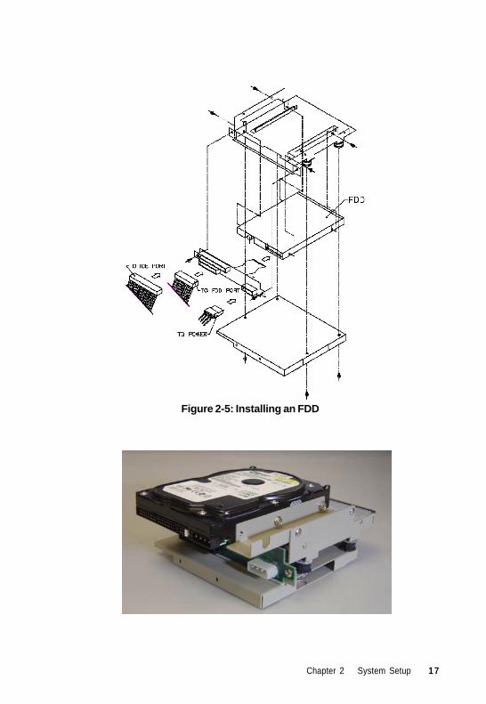
Figure 2-5: Installing an FDD
Chapter 2 System Setup 17
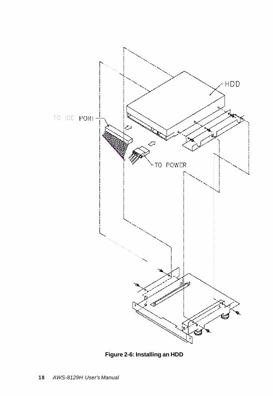
Figure 2-6: Installing an HDD 18 AWS-8129H User's Manual

Figure 2-7: Installing a CD-ROM
Chapter 2 System Setup 19

2.5 Connecting Cables
After inserting the CPU card into the chassis, connect the FDD, CD-ROM and HDD cables to the CPU card. In addition to the storage devices, three other cables need to be connected: the PS/2 mouse cable, keyboard cable. The PS/2 mouse cable is used to connect the mouse signal from the front panel PS/2 keyboard/mouse to the CPU card, as shown below. There is a keyboard control board in the system which integrates the keyboard signals. An internal keyboard cable needs to be connected to the CPU card as shown below.
VGA cable PS/2 cable
Figure 2-8 Connecting cables
20 AWS-8129H User's Manual
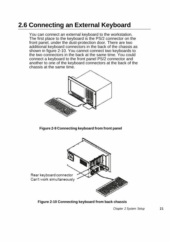
2.6 Connecting an External Keyboard You can connect an external keyboard to the workstation. The first place to the keyboard is the PS/2 connector on the front panel, under the dust-protection door. There are two additional keyboard connectors in the back of the chassis as shown in figure 2-10. You cannot connect two keyboards to the two connectors in the back at the same time. You could connect a keyboard to the front panel PS/2 connector and another to one of the keyboard connectors at the back of the chassis at the same time.
Figure 2-9 Connecting keyboard from front panel
Figure 2-10 Connecting keyboard from back hassis c
Chapter 2 System Setup 2 1

2.7 Panel Mounting
The AWS-8129H will stand on a shelf or a table, and it may be mounted within a panel. Dimensions for the case, the mounting flange, and the mounting bolts are shown in Figure 1-1.
Once you have added your cards, drives, and other equipment, you should switch on the AWS-8129H to confirm that it works. Then set the case within your panel aperture so that your screw holes line up with the mounting bolts on the flange of the AWS-8129H. Secure the bolts to the panel.
Figure 2-11: Panel mounting 22 AWS-8129H User's Manual

2.8 Rack Mounting
The AWS-8129H can also be mounted in a 19" rack. Make sure that all additional equipment has been installed correctly. Also make sure that all cabling (such as the monitor signal cable, the keyboard cable and the monitor power cable) has been reattached. Attach the rack to the case using screws on both sides of the case.
Figure 2-12: Rack mounting
Chapter 2 System Setup 23

24 AWS-8129H User's Manual
3
KBT-2002 Macro Key Programming
• Introduction • Macro Key Components • How to use Main.exe to edit Macro Key • Examples
3.1 Introduction
The KBT-2002 is equipped with programmable function keys (macro keys) that greatly enhances the operating interface. Macros, which are far more powerful than batch files; automate the most commonly used input sequences. They extend their functional reach within application pro- grams.
3.2 Macro keys Component
Macro keys (SF1 , SF2 ,...SF10) Ten programmable macro keys are located on the front panel of the work- station. Macro keys (SF11 , SF12 ,...SF30) These twenty programmable macro keys are customized models. If your workstation doesn’t have these twenty keys, you do not need to edit SF 11 to SF 30 when using the utility program, Main.exe, to edit the macro keys. The limitation of editing the macro keys When editing the macro keys, the number of characters is limited to 78. Every ten macro keys are defined as one block; there are three blocks in total. The size of each block is limited under 256 bytes. Please refer to the next section for editing the macro keys.
3.3 How to use Main.exe to edit Macro Key
First, copy all the files to your hard disk and/or make a backup disk. Take a look at the content of the utility disk; please find the .pad file that corre- sponds to your workstation, for example, AWS8129.pad for AWS-8129H series. Remember this file name, because you will need it to edit the macro keys.
26 AWS-8129H User's Manual
There ís an example within the subdirectory of the utility disk. Go into this subdirectory and look for a .txt file that corresponds to your worksta- tion, for example, AWS8129.TXT for the example for AWS-8129H series. You can use this file under the macro key edit program to practice.
Note 1: The keyboard translator utility main.exe pro- gram can be run under DOS mode only.
Note 2: The following windows illustrations are exam- ples only. You must follow the instruction and pay attention to the instructions which appears on you screen.
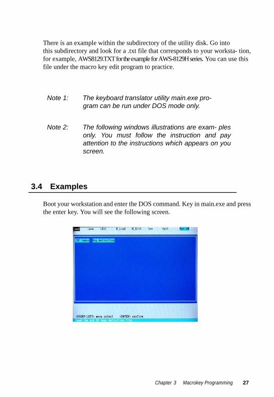
3.4 Examples
Boot your workstation and enter the DOS command. Key in main.exe and press the enter key. You will see the following screen.
Chapter 3 Macrokey Programming 27
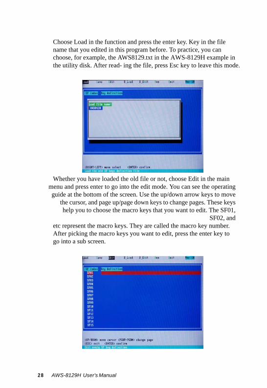
Choose Load in the function and press the enter key. Key in the file name that you edited in this program before. To practice, you can choose, for example, the AWS8129.txt in the AWS-8129H example in the utility disk. After read- ing the file, press Esc key to leave this mode.
Whether you have loaded the old file or not, choose Edit in the main
menu and press enter to go into the edit mode. You can see the operating guide at the bottom of the screen. Use the up/down arrow keys to move
the cursor, and page up/page down keys to change pages. These keys help you to choose the macro keys that you want to edit. The SF01,
SF02, and etc represent the macro keys. They are called the macro key number. After picking the macro keys you want to edit, press the enter key to go into a sub screen.
28 AWS-8129H User's Manual
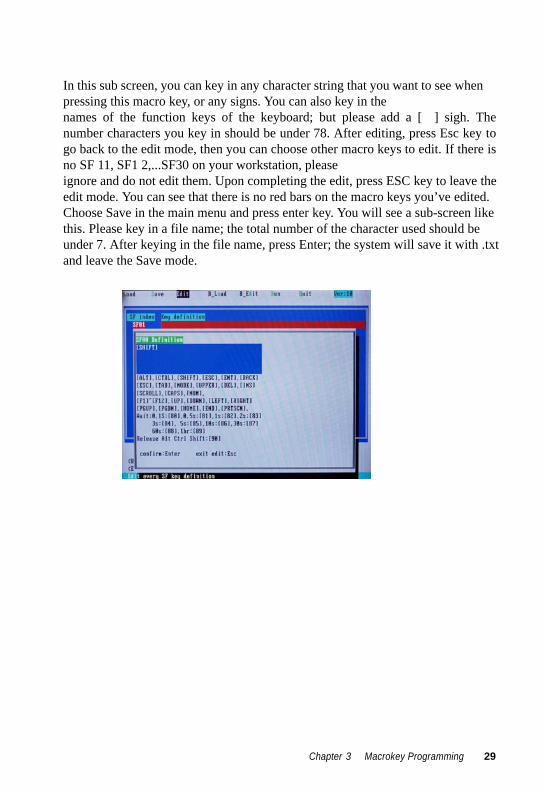
In this sub screen, you can key in any character string that you want to see when pressing this macro key, or any signs. You can also key in the names of the function keys of the keyboard; but please add a [ ] sigh. The number characters you key in should be under 78. After editing, press Esc key to go back to the edit mode, then you can choose other macro keys to edit. If there is no SF 11, SF1 2,...SF30 on your workstation, please ignore and do not edit them. Upon completing the edit, press ESC key to leave the edit mode. You can see that there is no red bars on the macro keys you’ve edited. Choose Save in the main menu and press enter key. You will see a sub-screen like this. Please key in a file name; the total number of the character used should be under 7. After keying in the file name, press Enter; the system will save it with .txt and leave the Save mode.
Chapter 3 Macrokey Programming 29
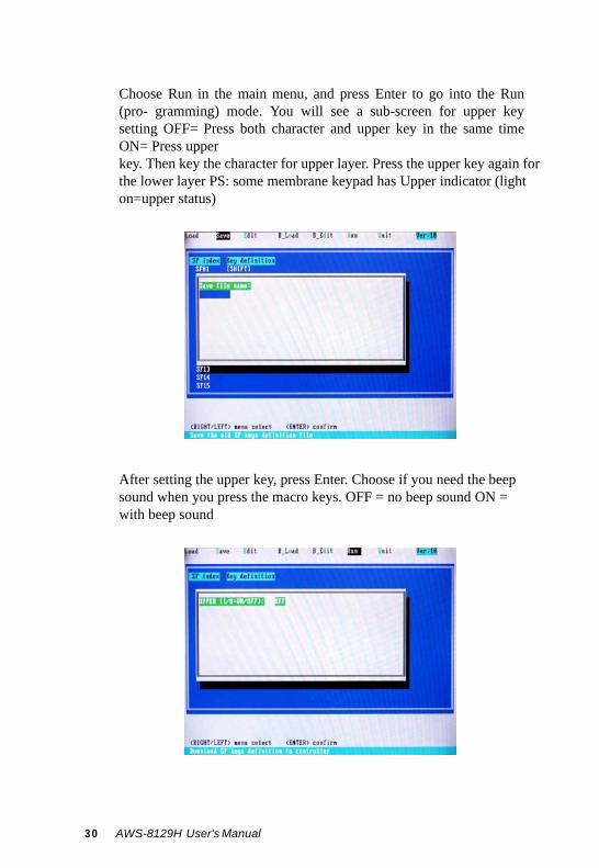
Choose Run in the main menu, and press Enter to go into the Run (pro- gramming) mode. You will see a sub-screen for upper key setting OFF= Press both character and upper key in the same time ON= Press upper key. Then key the character for upper layer. Press the upper key again for the lower layer PS: some membrane keypad has Upper indicator (light on=upper status)
After setting the upper key, press Enter. Choose if you need the beep sound when you press the macro keys. OFF = no beep sound ON = with beep sound
30 AWS-8129H User's Manual
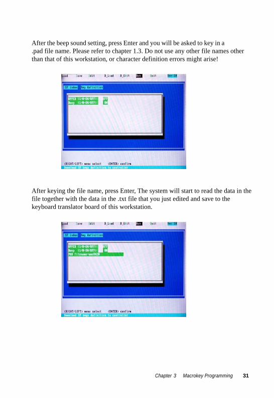
After the beep sound setting, press Enter and you will be asked to key in a .pad file name. Please refer to chapter 1.3. Do not use any other file names other than that of this workstation, or character definition errors might arise!
After keying the file name, press Enter, The system will start to read the data in the file together with the data in the .txt file that you just edited and save to the keyboard translator board of this workstation.
Chapter 3 Macrokey Programming 31
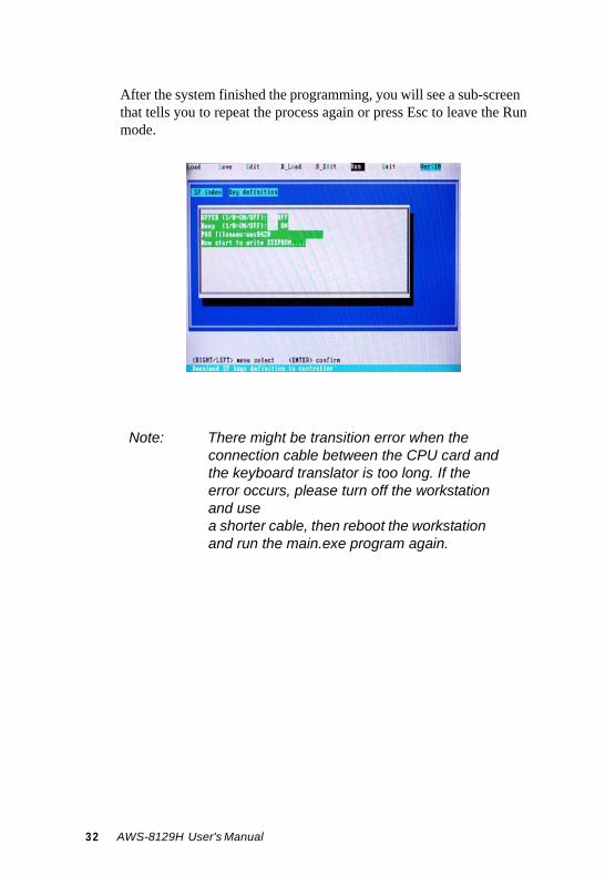
After the system finished the programming, you will see a sub-screen that tells you to repeat the process again or press Esc to leave the Run mode.
Note: There might be transition error when the connection cable between the CPU card and the keyboard translator is too long. If the error occurs, please turn off the workstation and use a shorter cable, then reboot the workstation and run the main.exe program again.
32 AWS-8129H User's Manual

4
Maintenance
• Detaching the backplane and bracket • Power supply • LCD maintenance • Keyboard translator • LED board • Touchscreen controller
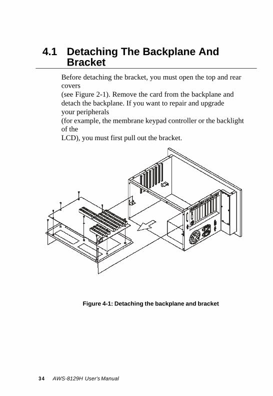
4.1 Detaching The Backplane And
Bracket
Before detaching the bracket, you must open the top and rear covers (see Figure 2-1). Remove the card from the backplane and detach the backplane. If you want to repair and upgrade your peripherals (for example, the membrane keypad controller or the backlight of the LCD), you must first pull out the bracket.
Figure 4-1: Detaching the backplane and bracket 34 AWS-8129H User's Manual
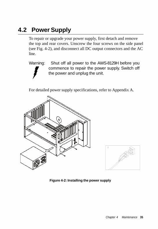
4.2 Power Supply
To repair or upgrade your power supply, first detach and remove the top and rear covers. Unscrew the four screws on the side panel (see Fig. 4-2), and disconnect all DC output connectors and the AC line.
Warning: Shut off all power to the AWS-8129H before you
commence to repair the power supply. Switch off the power and unplug the unit.
For detailed power supply specifications, refer to Appendix A.
Figure 4-2: Installing the power supply
Chapter 4 Maintenance 35
4.3 LCD Maintenance
In the normal working life of the AWS-8129H, you may have to replace the inverter, LCD or LCD backlight. Follow these instruc- tions:
1. Open the top and rear cover. (See Fig. 2-1.)
2. Disconnect the cable from the LCD controller and LCD.
3. Pull out the bracket which is located below the backplane.
4. Detach the bracket behind the front panel.
5. Disconnect the cables of the inverter, and the cables of the touchscreen controller (if applicable). Pull out the LCD bracket to change the inverter.
6. Unscrew the four screws, and pull out the LCD very carefully.
7. Unscrew the screws on the LCD (see Fig. 4-3), and then change the backlight.
Warning: The backlight is small and fragile. Use
caution when handling or replacing it. 36 AWS-8129H User's Manual
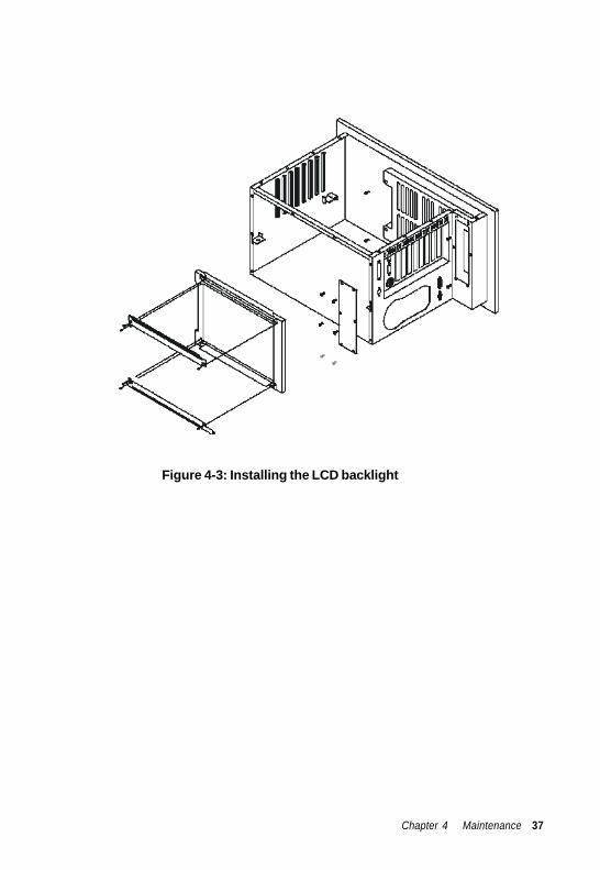
Figure 4-3: Installing the LCD backlight
Chapter 4 Maintenance 37

4.4 Keyboard Translator
The keyboard translator is an interface which switches the signal from the membrane keypad to the standard AT keyboard. There are six connectors on the board. On top of the board, there are two connectors linking two flat cables with the larger membrane keypad (as shown in Fig. 4-5). On the side of the board, there are four connectors. For connection details, refer to Fig. 4-5.
When servicing the keyboard translator:
1. Switch off the power, and detach the main power cord.
2. Detach the work drawer and cover from the AWS-8129H unit.
(See Fig. 2-1.)
3. Pull out the work drawer out as far as it will go.
4. Remove the keypad connector protective bracket.
5. Carefully detach all cables connected to the keyboard translator. (See Fig. 4-5.)
6. Unscrew the four screws on the corners, pull out the keyboard translator, and replace it.
38 AWS-8129H User's Manual
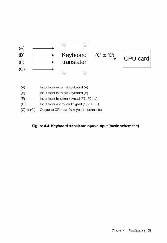
(A)
Keyboard (B) (C) to (C')
translator CPU card (F) (O)
(A) Input from external keyboard (A)
(B) Input from external keyboard (B)
(F) Input from function keypad (F1, F2, ...)
(O) Input from operation keypad (1, 2, 3, ...)
(C) to (C') Output to CPU card's keyboard connector
Figure 4-4: Keyboard translator input/output (basic schematic)
Chapter 4 Maintenance 39
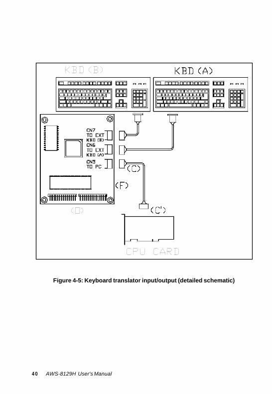
Figure 4-5: Keyboard translator input/output (detailed schematic) 4 0 AWS-8129H User's Manual

4.5 LED Board
It is very unlikely that the LED board will have to be replaced. There are two indicators in the LED board: HDD and power. You do not need to remove the backplane and bracket to replace the LED board. Simply detach the bays for the FDD, HDD and slim CD-ROM drive, and then unscrew the three screws fixed into the panel. Before removing the LED board, carefully detach the cables by pulling them down.
4.6 Touchscreen Controller
To service or replace the touchscreen controller:
1. Open the top and rear cover. (See Fig. 2-1.)
2. Disconnect the cable from the LCD controller and LCD.
3. Pull out the bracket which is located below the backplane.
4. Detach the bracket behind the front panel.
5. Disconnect the cables of the inverter, and the cables of the touchscreen controller.
6. Replace the touchscreen controller.
Caution: Do not bend the touchscreen tail which is attached to the touchscreen sensor.
Chapter 4 Maintenance 41

4 2 AWS-8129H User's Manual
A
Power Supply Specifications
250 watt power supply
-48 VDC power supply
24 VDC power supply
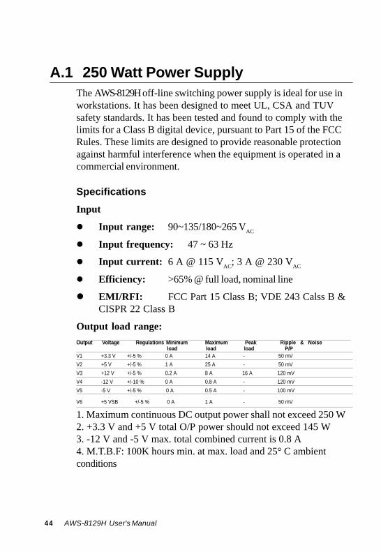
A.1 250 Watt Power Supply
The AWS-8129H off-line switching power supply is ideal for use in workstations. It has been designed to meet UL, CSA and TUV safety standards. It has been tested and found to comply with the limits for a Class B digital device, pursuant to Part 15 of the FCC Rules. These limits are designed to provide reasonable protection against harmful interference when the equipment is operated in a commercial environment.
Specifications
Input
Input range: 90~135/180~265 VAC
Input frequency: 47 ~ 63 Hz
Input current: 6 A @ 115 VAC; 3 A @ 230 VAC
Efficiency: >65% @ full load, nominal line
EMI/RFI: FCC Part 15 Class B; VDE 243 Calss B & CISPR 22 Class B
Output load range:
Output Voltage Regulations Minimum Maximum Peak Ripple & Noise load load load P/P
V1 +3.3 V +/-5 % 0 A 14 A - 50 mV V2 +5 V +/-5 % 1 A 25 A - 50 mV V3 +12 V +/-5 % 0.2 A 8 A 16 A 120 mV V4 -12 V +/-10 % 0 A 0.8 A - 120 mV V5 -5 V +/-5 % 0 A 0.5 A - 100 mV
V6 +5 VSB +/-5 % 0 A 1 A - 50 mV
1. Maximum continuous DC output power shall not exceed 250 W 2. +3.3 V and +5 V total O/P power should not exceed 145 W 3. -12 V and -5 V max. total combined current is 0.8 A 4. M.T.B.F: 100K hours min. at max. load and 25° C ambient conditions
44 AWS-8129H User's Manual

Reset time:
When the power supply has automatically shut down, and the short circuit, over-current and/or over-voltage conditions have ceased to exist, power will be automatically recycled to restart the power supply within 3 seconds of such return to normal conditions.
No load start:
When the power supply is switched on but with no load connected, the power supply does not get damaged, and it is still completely safe for users.
Transient response:
Dynamic load change: ±50% of maximum rating load
Recovery time: 500 μs max.
Reliability
Mean time between failures (MTBF): 100,000 hours minimum
Environmental specifications
Operating temperature: 0 ~ 50° C
Storage temperature: -40 ~ 60° C
Operating and storage humidity: 10 ~ 95%
RH
Operating altitude: sea level ~ 15,000 ft
Storage altitude: sea level ~ 50,000 ft
International standards compliance
Safety: UL 1950 CSA 22.2 No. 234 TUV EN 60950
EMI: FCC Part 15 Subpart J Class B
Appendix A Power Supply Specifications 45
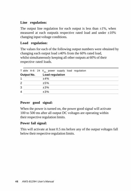
Line regulation:
The output line regulation for each output is less than ±1%, when measured at each outputís respective rated load and under ±10% changing input voltage conditions.
Load regulation:
The values for each of the following output numbers were obtained by changing each output load ±40% from the 60% rated load, whilst simultaneously keeping all other outputs at 60% of their respective rated loads.
T able A-6: 24 VDC power supply load regulation Output No. Load regulation 1 ±4% 2 ±5% 3 ±3% 4 ±3%
Power good signal:
When the power is turned on, the power good signal will activate 100 to 500 ms after all output DC voltages are operating within their respective regulation limits.
Power fail signal:
This will activate at least 0.5 ms before any of the output voltages fall below their respective regulation limits.
46 AWS-8129H User's Manual

General features
Efficiency:
65% typical when measured at nominal input and rated load.
Input protection:
Protection against wrong polarity if the +24 V input voltage is mistakenly reversed.
Output protection:
If for some reason the power supply fails to control itself, the built-in over-voltage protection circuit will shut down the outputs to prevent damage to external circuits. The trip point of the crowbar circuit is approximately 5.7 ~ 7.0 V. The power supply will go into hiccup mode under short circuit or overload conditions, and will recover automatically when such conditions cease to exist.
Environmental specifications
Operating temperature: 0 ~ 45°
C Storage temperature: -40 ~ 75°
C
International standards compliance
Safety: UL 1950 D3 CSA 234 TUV EN 60950
Appendix A Power Supply Specifications 47

48 AWS-8129H User's Manual
B
Touchscreen Driver Installation
Introduction
Windows 98/2000
Windows XP
B.1 Introduction
The AWS-8129H's touch screen drivers for different operating systems are included in the "HMI Products Drivers Utilities" CD-ROM. You could install the touch screen drivers from the utility CD-ROM; the AWS-8129H has an optional CD-ROM drive, or a floppy disk drive, which is a standard device of the AWS-8129H series of products. If you want to install the drivers from a floppy disk, you need to copy the drivers from the utility CD-ROM first.
Touch screen drivers for Windows 98/2000 and Windows XP are now supported. The touch screen drivers for the supported OS are under the following path:
Windows 98: \TouchScreen-DRV\Penmount USB\Windows Driver V4.1-1003
Windows 2000: \TouchScreen-DRV\Penmount USB\Windows Driver V4.1-1003 Windows XP: \TouchScreen-DRV\Penmount USB\Windows XP Driver V4.0 (WHQL)
Note: Following the installation procedures, "D"
represents the CD-ROM or floppy disk drive. 5 0 AWS-8129H User's Manual
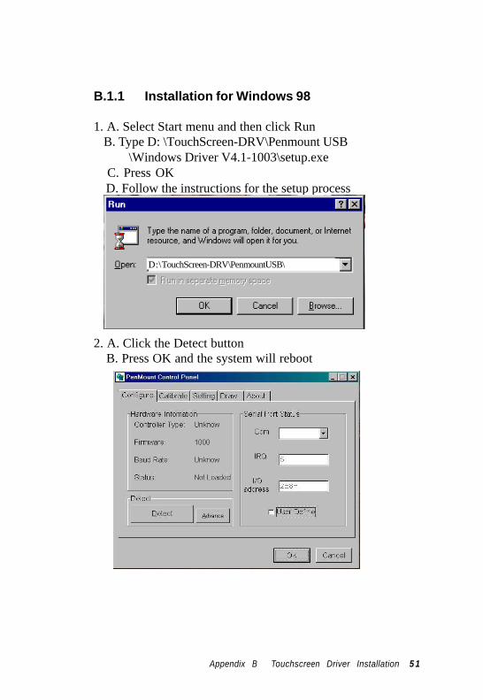
B.1.1 Installation for Windows 98
1. A. Select Start menu and then click Run B. Type D: \TouchScreen-DRV\Penmount USB
\Windows Driver V4.1-1003\setup.exe C. Press OK D. Follow the instructions for the setup process
D:\TouchScreen-DRV\PenmountUSB\
2. A. Click the Detect button B. Press OK and the system will reboot
Appendix B Touchscreen Driver Installation 5 1
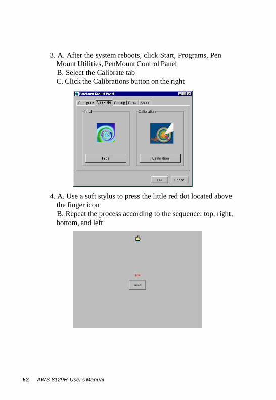
3. A. After the system reboots, click Start, Programs, Pen Mount Utilities, PenMount Control Panel B. Select the Calibrate tab C. Click the Calibrations button on the right
4. A. Use a soft stylus to press the little red dot located above the finger icon B. Repeat the process according to the sequence: top, right, bottom, and left
5 2 AWS-8129H User's Manual

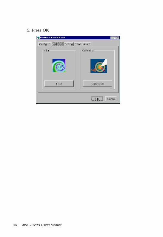
5. Press OK
Appendix B Touchscreen Driver Installation 5 3

B.1.2 Installation for Windows XP 1. A. Select Start menu and then click Run
B. Type \TouchScreen-DRV\Penmount USB\Windows XP Driver V4.0 (WHQL)setup.exe C. Press OK D. Follow the instructions for the setup process
D:\TouchScreen-DRV\Penmount USB\
2. A. Click the Detect button B. Press OK and the system will reboot
5 4 AWS-8129H User's Manual

3. A. After the system reboots, click Start, Programs, Pen
Mount Utilities, PenMount Control Panel B. Select the Calibrate tab C. Click the Calibrations button on the right
4. A. Use a soft stylus to press the little red dot located above the finger icon B. Repeat the process according to the sequence: top, right, bottom, and left
Appendix B Touchscreen Driver Installation 5 5
5. Press OK
5 6 AWS-8129H User's Manual
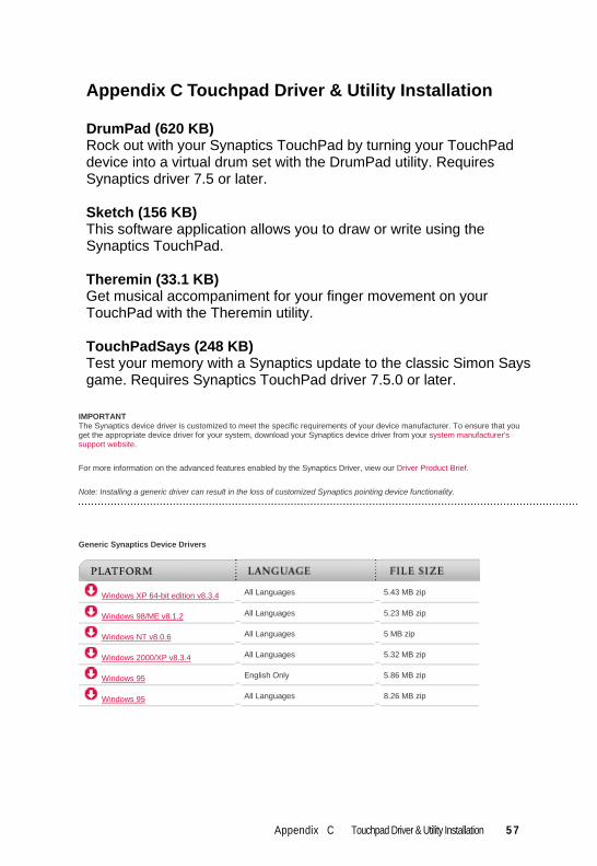
Appendix C Touchpad Driver & Utility Installation DrumPad (620 KB) Rock out with your Synaptics TouchPad by turning your TouchPad device into a virtual drum set with the DrumPad utility. Requires Synaptics driver 7.5 or later. Sketch (156 KB) This software application allows you to draw or write using the Synaptics TouchPad. Theremin (33.1 KB) Get musical accompaniment for your finger movement on your TouchPad with the Theremin utility. TouchPadSays (248 KB) Test your memory with a Synaptics update to the classic Simon Says game. Requires Synaptics TouchPad driver 7.5.0 or later.
IMPORTANT The Synaptics device driver is customized to meet the specific requirements of your device manufacturer. To ensure that you get the appropriate device driver for your system, download your Synaptics device driver from your system manufacturer's support website.
For more information on the advanced features enabled by the Synaptics Driver, view our Driver Product Brief.
Note: Installing a generic driver can result in the loss of customized Synaptics pointing device functionality.
Generic Synaptics Device Drivers
Windows XP 64-bit edition v8.3.4
All Languages 5.43 MB zip
Windows 98/ME v8.1.2
All Languages 5.23 MB zip
Windows NT v8.0.6
All Languages 5 MB zip
Windows 2000/XP v8.3.4
All Languages 5.32 MB zip
Windows 95
English Only 5.86 MB zip
Windows 95 All Languages 8.26 MB zip
Appendix C Touchpad Driver & Utility Installation 5 7

5 8 AWS-8129H User's Manual


