30
FEATURING AXIAL-FLOW ® 7010/8010 PRODUCTIVITY GUIDE • Safety • Service Inspections • Maintenance • Operation • Troubleshooting • AFS • Storage

FEATURING
AXIAL-FLOW® 7010/8010 PRODUCTIVITY GUIDE
• Safety• Service Inspections• Maintenance• Operation• Troubleshooting• AFS• Storage

Thank you very much
for reading.
PLEASE CLICK HERE. Then back to the site.
At the bottom of the
page,
free add to card.
Then get more free
information

TITLEGENERAL INFORMATION
2
IntroductionIn 1977, the first single rotor multi-crop combine wasintroduced, and the Axial-Flow® combine quickly found its homein farm fields throughout North America, and around the world.The rest is history. Thirty years and over 144,000 combineslater, the Case IH Axial Flow is the harvesting benchmark, andan agricultural legend. More Case IH Axial-Flow combines haveharvested crops than all other rotaries—combined.
At the heart of Axial-Flow design are six uncompromising coreprinciples. The single rotor Axial-Flow design boasts SIMPLICITYthat reduces maintenance cost and contributes to overalllower ownership costs. GRAIN QUALITY and GRAIN SAVINGS area direct result of the single rotor design. Basic design and30 years of history give the Axial-Flow ADAPTABILITY unlikeany other combine, and the MATCHED CAPACITY of all combinesystems means no productivity-robbing internal bottlenecks.All this adds up to RESALE VALUE that leads the industry.
Strong resale value depends not only on the integrity ofthe machine, but the ability to update older machines withnew technology, protecting your investment. And equallyimportant is the solid support you receive from your localCase IH dealer. Your dealer’s investment in their stock ofgenuine Axial-Flow service parts, technician training,maintenance programs and credit support helps all yourCase IH products retain resale value.
With the Axial-Flow 7010/8010 , Case IH is writing the latestchapters in the Axial-Flow story. CNH offers a full selectionof headers including standard and residue chopping cornheads up to 12 rows; auger grain headers up to 35 feet; anddraper headers up to 40 feet in width. The all-gear Power Plusvariable speed feeder drive allows precise feeder and headerspeed control, automatically adjusting to ground speed.
Perfection of the AFX rotor boosts threshing capacity withreduced power requirements, while maintaining superior grainquality andseparation. Interchangeable rotormodulescustomizethreshing and separating to specific crops and conditions, andthe Power Plus drive system gives operators precise speedcontrol and efficient power transmission to the rotor. With thestandard in-cab rotor reverser and inching feature, the PowerPlus drive makes the slug wrench obsolete.
Figure 2.1
Figure 2.3
Figure 2.2
Figure 2.4

TITLEGENERAL INFORMATION
3
Introduction (cont.)The self-leveling cleaning system features a larger, hydraulically-driven CrossFlow fan and active grain pan that stratifies grainbefore reaching the pre-sieve. The leveling system allows combineoperation on slopes up to 12% (8010) or 14% (7010) whilemaintaining a level cleaning system. An innovative Tri-Sweeptailings processor efficiently re-threshes tailings, returning themto the grain pan for re-separation. Residue handling systemsadjust spreading width to distribute discharge evenly behindheaders as wide as 42 feet.
Grain tanks holding 315 and 350 bushels for the 7010 and8010 respectively, and unloading at 3.2 bushels per secondsupport optimum productivity in the highest yielding crops.Unloading augers discharge up to 21 feet from the combine,maintaining a safe distance between trucks or grain carts andthe widest headers.
The highest yields, toughest crop, and most demanding terrainand field conditions do not slow down the Axial-Flow 7010/8010combines, with 350 HP in the 7010 and 400 HP driving the8010. Power Boost Mode gives operators an added edge whenoperations such as unloading-on-the-go demand extra power tokeep up ground speed and harvest productivity.
Maintenance is made easy with large, easy-opening sideinspection doors with standard service lights. Easy access to theradiator and filters promotes regular service, and sight gauges onthe transmission and gear cases allows level checks at a glance.The Power Plus drive system drastically reduces the numberof belts and chains, promoting reliable operation with reducedservice demands.
Operators work at maximum productivity on long harvest days inthe climate controlled comfort of the Axial-Flow cab. Focalizedcab mounting and air suspension seat take the vibration andshock out of cruising through the field, and user-friendly righthand controls move with the seat to keep them in easy reachfor maximum comfort and efficiency. Over 62 square feet ofglass and superior lighting, including optional HID lights, allowsoperators to see every inch of the head and surrounding fieldconditions.
Standard yield and moisture sensors team up with the in-cabUniversal Display Plus or Pro600 monitor to give operatorsinstant feedback on combine productivity and crop yield, and theability to store data for summary display. Add one of two optionalGPS receivers, and accurate yield and moisture maps becomethe ultimate tool to fine-tune crop population, pest control andnutritional requirements in future years. The AFS252 receiversupports the optional AccuGuide™ auto guidance system.
Figure 3.1
Figure 3.3
Figure 3.2

SAFETY / FIRE PREVENTION
SafetyHarvest is the culmination of a full year of hard work and greatinvestment. We know harvest “windows of opportunity” are notalways as wide as you would like, with weather and crop conditionshaving the final say on when the crop gets into the bin. Makesure you spend every available day harvesting, not sidelinedbecause poor judgment resulted in an accident. Observe allSafety Instructions in the combine Operator’s Manual, and thesespecific safety rules, for a safe and profitable harvest season.
General Safety Rules• Be sure you re-read the Operator’s Manual to review all safety instructions
• Be sure you read and understand the safety messages on all decals on your combine
• Never start or move the combine until you are sure everyone is out of the way
• Never start the combine until the operator is familiar with all controls. This rule applies even if an experienced operator/ trainer is present. Waiting until a quick decision is required to prevent an accident is not a good learning experience.
• Always place the transmission in neutral before attempting to start the engine
• Do not allow riders (except during training)
• Set the parking brake, turn off the engine and remove the key before leaving the cab for cleaning, adjusting, or lubricating
• Never enter the grain tank or engine compartment when the engine is running
• Many of the combine systems are electronically actuated. Unlike mechanical linkages that have a distinct and visible outcome when shifted or adjusted, activity such as unplugging an actuator may result in unexpected component movement. This accents the need to stop the combine engine before performing any service operation.
• Always stop the combine engine when refueling. Do not smoke while refilling the fuel tank.
• Solidly block the header up, or lower the feeder cylinder safety stand before working on or under the header (see
figure 4.1)
• Keep ladders, steps, and platforms free of trash and mud accumulations
• Always keep all guards and shields in place
• Drive at moderate speeds in the field and on the road. Keep the combine in gear when going down hill.
• Use extreme caution when removing the radiator cap to avoid contact with hot pressurized coolant. Allow the engine to cool before opening the system.
• Be sure everyone is clear of the area before unloading grain. Grain entering a truck, trailer or grain cart at over 3 bushels per second can trap an adult in seconds.
• Dress appropriately when performing service work. Do not wear loose clothing that can become entangled with the machine.
4
Think safe … Work safe … Be safe.
Fire PreventionFew things could ruin an otherwise rewarding harvest morethan a devastating combine fire. By nature, mature crops aredry and dirty, and are sources of considerable debris that canaccumulate on harvesting equipment. During busy harvest-time, operators should take the time to clean the combine daily.The most appropriate cleaning time is at the end of the day.
• Attempts to perform only major, time-consuming cleanings on a less-frequent basis will likely require MORE TIME in the course of the harvest season. Make a proactive commitment to devote a few minutes to cleaning on a daily basis. Cleaning time is also a good time to perform a basic visual machine inspection.
Some additional “food for thought.” Modern, high-productivitycombines are powerful machines, and along with power comesheat. Fire cannot start without heat and fuel. You cannot removethe heat from the engine, hydraulics and other hard-workingsystems, but you can remove the fuel source by keeping yourcombine clean.
Specific areas where high operating temperatures suggest extracleaning effort are:
• The engine, especially the exhaust system and turbocharger
• Hydrostatic pump, motor and hydraulic lines and tubes
• Brakes
• Electrical components
• Engine drives and all moving parts
• Batteries and battery cables
Equip your combine with at least two fire extinguishers – one nearthe cab and another where it can be reached from the ground.
• Have at least one water-charged extinguisher on your combine. However, use a water extinguisher only on crop debris. Water applied to an oil fire may spread the flames.
• Watch for fuel or hydraulic fluid leaks. Correct leaks immediately and clean the machine thoroughly after leaks or spills. Residual hydraulic fluid or fuel mixed with trash creates a very combustible mixture. This can make a fire much harder to control.
• When transporting on the highway, engage the “Road Mode” switch. Double-check bridge and overhead power line clearances.
• Takefrequentbreakstomaintainmaximiumattention.Analert operator is in a better position to handle emergencies.
Figure 4.1
SERVICE INSPECTIONS
5
Take Full Advantage of its CapabilitiesHave you, or did someone you know purchase a new combine in the lastfew years and continued to use it in much the same way as the combine itreplaced? Many times operators do not fully realize and take advantage ofmodern features. As a result of not fully utilizing the combine’s features, theowner may not be receiving all the value from the money spent.
Many of the items suggested in this booklet can be completed by the ownerwhen preparing for the season or the operator when starting a new field.Other adjustments, service procedures, or repairs might be more effectivelycompleted by your dealer’s trained service technicians.
MAINTENANCE CHOICES, BE PREPARED FOR DEMANDING CONDITIONS
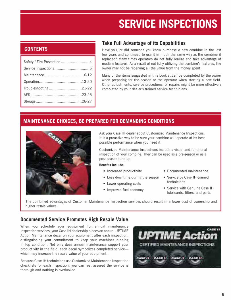
• Increased productivity
• Less downtime during the season
• Lower operating costs
• Improved fuel economy
• Documented maintenance
• Service by Case IH-trained technicians
• Service with Genuine Case IH lubricants, filters, and parts
Ask your Case IH dealer about Customized Maintenance Inspections.It is a proactive way to be sure your combine will operate at its bestpossible performance when you need it.
Customized Maintenance Inspections include a visual and functionalinspection of your combine. They can be used as a pre-season or as apost-season tune-up.
Benefits include:
The combined advantages of Customer Maintenance Inspection services should result in a lower cost of ownership andhigher resale values.
Documented Service Promotes High Resale ValueWhen you schedule your equipment for annual maintenanceinspection services, your Case IH dealership places an annual UPTIMEAction Maintenance decal on your equipment after each inspection,distinguishing your commitment to keep your machines runningin top condition. Not only does annual maintenance support yourproductivity in the field, each decal symbolizes completed service—which may increase the resale value of your equipment.
Because Case IH technicians use Customized Maintenance Inspectionchecklists for each inspection, you can rest assured the service isthorough and nothing is overlooked.
CONTENTS
Safety / Fire Prevention ..........................4
Service Inspections................................5
Maintenance ....................................6-12
Operation.......................................13-20
Troubleshooting ..............................21-22
AFS...............................................23-25
Storage..........................................26-27

6
MAINTENANCE
8
2
3
5
4
71
6
Daily maintenance items to check at the end of the day while themachine is at operating temperature.
Check PTO gearbox oil level
Empty the rock trap
Visually inspect the cooling system rotary screen
Check tire inflation
Additional checks are recommended and should be performed prior tostarting-when the engine is cooled to ambient temperature.
Check the engine oil level
Check coolant recovery tank level sight glass
Check hydraulic reservoir level sight glass
Confirm audible alarms and indicator lamps function properly on startup
2
4
3
6
5
7
1
During harvest time, it is easy to get in a hurry and perhaps neglect some “minor” maintenance items. Before long (in an effortto get to the field a few minutes sooner), more items may start to seem “minor.” Then, a breakdown may be a reminder that nomaintenance item is “minor.” Not only will the repair be more costly than maintenance, it will be much more time-consuming. Be sure to follow all the maintenance recommendations in your Operator’s Manual, and enhance your combine productivity all season long.
8
The Axial-Flow 7010/8010 combines are designed to require a minimum of daily maintenance. Complete daily maintenancesteps are detailed in the combine Operator’s Manual.
Grease fittings requiring regular service include:
• Cleaning shoe drive eccentrics (50 Hr.)
• Final drive half-shaft couplers (100 Hr.)
• Powered rear axle kingpins (100 Hr.)
• Grain elevator slip clutch (300 Hr.)
• Header drive gearbox (300 Hr.)
• Header driveshaft pillow block (300 Hr.)
• Header driveshaft sliding splines (300 Hr.)
• Header driveshaft upper spline (300 Hr.)
• Unloader chain idler support (300 Hr.)
• Rotor front bearing (600 Hr.)
• Beater/chopper shaft bearings (600 Hr.)
4

MAINTENANCE
7
Additional Service RecommendationsEngine Air FilterThe engine air filter should be serviced only when there is an“Air Filter Blocked” alarm on the operator’s display (see figure 7.1).
• Replacing plugged filters is the recommended method to assure optimum engine protection
• If the filter is cleaned, use extreme care, directing low- pressure air from the inside to dislodge dirt. To avoid damage, do not strike the inside of the element with the air wand.
• NEVER tap or pound the element on a hard surface to dislodge dirt, as damage is likely to occur
• Check the filter element with a light inside the element after cleaning to assure the element paper and the connection of the pleats to the element end plates has not been damaged
• Remove the inner safety element only if it is to be replaced(see figure 7.2)
Engine Oil and FilterCheck the engine oil level daily, after the engine has beenstopped at least 5 minutes (see figure 7.3).
• The oil level on the dipstick should be between the minimum and maximum level marks
• DO NOT OPERATE THE ENGINE if the level is below the minimum mark
• Do not overfill the crankcase above the maximum mark
The engine oil and filter change interval is 300 operating hours.
• Always use a top-quality engine oil. Case IH No. 1® SAE 15W40 engine oil has been specifically formulated for heavy duty, high-temperature operation in diesel engines.
• Oil must meet API CH-4 specifications
• Crankcase oil capacity for the 10.3 liter engine is 8.3 US Gal. (32 liters)
Crankcase BreatherThe crankcase breather has an indicator that sets if service isrequired (see figure 7.4). Check the sight gauge periodicallyfor a red pin that may become visible. Change the filter every1200 operating hours.
Anti-Freeze/Coolant MaintenanceEngines in today’s combines operate at near full loadconditions a high percentage of the time The cooling systemmust rid the engine of significant heat in these conditions.Good maintenance is necessary to keep the system working attop efficiency, while protecting internal engine components.
• The minimum interval for checking the coolant level in the expansion tank is 50 hours. Given the ease of glancing at the sight glass, a daily check is good insurance that the level is correct (see figure 8.1).
Figure 7.1
Figure 7.2
Figure 7.4
Figure 7.3

8
MAINTENANCE
Additional Service Recommendations (cont.)Anti-Freeze/Coolant Maintenance (cont.)• If coolant must be added, refer to the Operator’s Manual safety requirements prior to removing the radiator cap.
• If the cap must be removed while the system is hot, protecthands with a thick layer of rags to absorb spilled coolant.
Do not wear gloves. Gloves can become soaked with hot coolant and burn the skin before the they can be removed.
• Use Case IH XHD antifreeze coolant. Mix with clean, soft water in a 50/50 ratio. Do not use automotive grade coolant
available from common retail outlets. It is not low silicate, and is inadequate for heavy-duty use.
• Cooling system capacity is 11.1 US Gallons (42 liters)
• Replace the coolant every 1200 operating hours. Refer to the Operator’s Manual.
Coolant ConditionerAxial-Flow 7010/8010 combines are factory-filled with a pink-colored, heavy-duty ethylene glycol antifreeze that containsDCA4 additive to prevent corrosion in the cooling system.
• Engines on Axial-Flow 7010/8010 combines do not have a coolant filter, unlike some past engines
• When the coolant is changed, the antifreeze used to refill the system must contain some DCA4 to continue the corrosion protection.
• Is not good to “over-apply” DCA4. A test kit is available to evaluate coolant corrosion protection.
Cooling system corrosion protection can be properly maintainedwith the following parts:
• Part No. CC2602—Fleetguard™ test kit for checking the DCA level in the cooling system
• Part No. DCA60LJ—Fleetguard DCA4 coolant additive (1 pint)
• Part No. 332398A1—Heavy-duty ethylene glycol antifreeze with DCA4 additive (1 Gallon)
Air Intake Rotary ScreenCheck the rotary screen to assure screen sections are notdamaged, out of place, or missing (see figure 8.2).
• Open the rotary screen and assure debris is not accumulated on radiator fins, restricting air flow (see
figure 8.3)
• Check for debris on other cooling elements, including intercooler, PTO gearbox oil cooler, hydraulic oil cooler, air conditioning condenser and fuel cooler.
• A “Service Hinge” can be released to allow the cooling elements to open further for extensive cleaning. Refer to the Operator’s Manual for instructions for proper use.
• Check cutoff plate brushes for light contact with the screen. Adjustment may be necessary as the brushes wear (see
figure 8.4). Refer to the Operator’s Manual for adjustment procedures, which are different between combine models.
Figure 8.1
Figure 8.2
Figure 8.3
Figure 8.4

MAINTENANCE
9
Additional Service Recommendations (cont.)Engine CompartmentWhile cleaning, visually inspect the engine compartment forsigns of leaks, debris on the alternator screen, (see figure 9.1) belt tension and condition, and correct connection andtightening of hoses and clamps (see figure 9.2).
Fuel SystemThe most reliable way to prevent fuel-related performanceissues is to purchase only high quality, low sulfur fuel from areputable supplier. Refer to the Operator’s Manual for detailedfuel quality specifications.
• Fuel tank capacity is 264 gallons
• Fuel level gauge in cab post display, low fuel warning is displayed on monitor
• Re-fill with fuel at the end of the day if possible to minimize moisture condensation in the tank
• Check the pre-filter/water separator daily and drain accumulated water if necessary (see figure 9.3)
• Replace the pre-filter every 600 hours, or sooner if engine performance reduction is observed
• Replace the final fuel filter every 600 hours (see figure 9.4)
Figure 9.1
Figure 9.2
Figure 9.3
Figure 9.4
Bio-diesel FuelThe use of Bio-diesel fuel is on the rise. A bio-fuel blend, up toa maximum of 5% (B5) has been approved for use in Case IHdiesel engines. While bio-diesel has distinct advantages suchas its clean burning characteristics, users of bio-diesel shouldbe aware of some specific conditions.
• Bio-diesel blends attract more moisture, and may require more frequent water separator draining
• Bio-diesel should not be left in engines that are stored for more than 4 months
• A lower cloud point may contribute to harder cold-weather starting, making bio-diesel less attractive than conventional diesel fuel for winter use
• Depending on fuel quality, more frequent filter changes may be required
In addition to low-emissions, some other bio-diesel advantagesinclude:
• Bio-diesel mixes well with conventional diesel fuel
• Oil change intervals are not affected with bio-diesel use
As with all other fuels, purchase high quality Bio-diesel fuelfrom reputable suppliers to assure trouble-free combineoperation.

10
MAINTENANCE
Additional Service Recommendations (cont.)Hydraulic SystemThe hydraulic system works hard propelling, lifting, turningand controlling functions on your combine.
• Use only the finest hydraulic fluid, namely Case IH AKCELA Hy-Tran® Ultra hydraulic transmission fluid … the only brand guaranteed to deliver complete protection. Don’t take a chance on ordinary lubricants.
• When checking the oil level, make sure the combine is parked on a level area, and all cylinders are retracted
• The hydraulic oil level is checked by viewing a sight glass on the oil reservoir (see figure 10.1). Add oil should the level decrease to the bottom of the sight glass. Do not fill above the top of the sight glass.
• Replace the hydraulic oil and filter every 1200 hours as specified in the Operator’s Manual. System capacity is 15 US Gallons (57 liters).
• Wipe dust and dirt from the header hydraulic hose connection block before disconnection and connection of the head to reduce dirt entry into the hydraulic system
PowerPlus Drive SystemThe PTO gearbox serves as the reservoir for the PowerPlusdrive hydrostatic system. The oil level should be checked daily,following a specific procedure (see figure 10.2).
• The best time to perform the procedure is at the end of the day. If the oil is not warm, operate the engine at least 10 minutes to warm the oil, then with the separator and feeder engaged for 5 minutes.
• If the oil is warm, but the drives have not been operated in at least 30 minutes, operate for 5 minutes with the separator and feeder engaged
• Stop the engine, and allow the unit to set 15 minutes before checking oil level
• Use a “double-dip” method to check oil level. Pull the dipstick out, wipe clean and full re-insert. Then remove and check oil level on the dipstick.
• Must be between minimum and maximum marks
• Use Case IH AKCELA Hy-Tran Ultra oil
Roller ChainDrive chains work hard on a combine, and proper maintenanceis crucial for reliable operation. Most important, consult theOperator’s Manual for tension adjustments and specifications(see figure 11.1).
• Insufficient tension allows chains to whip during operation, placing shock loads on the chain, sprockets, shafts, and bearings
• Loose chains do not transmit power at a consistent speed, and in extreme cases can slip or jump off sprockets
• Excessive tension places added load on the chains, sprockets and associated parts
• Follow Operator’s Manual instructions for the adjustment of crop carrying chains such as the feeder and elevators
• Chain alignment is critical. Make sure chain is properly aligned, especially after performing repairs.
• Unless specified, operator choice determines if chains are lubricated, or run dry. If chains are initially lubricated, re-lubricate regularly to flush contaminants from the chain and maintain lubricant protection.
• Use chain lubricant that is formulated to cling to the chains, providing longer lasting protection with less oil spray onto the machine
BeltsThe same basic standards apply to belts, as chains. Followspecified tension adjustments to promote long belt life andefficient operation (see figure 11.2).
• Avoid overstressing components with excessive tension
• Inadequate tension allows belts to slip, accelerating wear and adversely affecting performance
• Belt alignment and tension not properly maintained may result in slippage, uneven wear, and poor tracking
• Alignmentisparticularlyimportantwithmulti-veeandpoly-vee belts. Uneven loading will affect belt life and efficiency if improperly aligned.
Figure 10.1
Figure 10.2
PTO GEARCASEDIPSTICK
ROTOR GEARCASEDIPSTICK

MAINTENANCE
11
Additional Service Recommendations (cont.)
Figure 11.1
Figure 11.2
Gearbox Service Specifications
Gearbox Oil Check(Hrs.)
Oil Change(Hrs.) Oil Type
Transmission 300 600 Case IH AKCELA 135H EPSAE 80W90 GearLube
Final Drives 300 600 Case IH AKCELA 135H EPSAE 80W90 GearLube
UnloaderDrive 300 600 Case IH AKCELA 135H EP
SAE 80W90 GearLube
UnloaderTube 300 600 Case IH AKCELA 135H EP
SAE 80W90 GearLube
Tailings 600 600 Case IK AKCELA Hy-TranUltra
Bubble-UP(two) 300 600 Case IK AKCELA Hy-Tran
Ultra
Rotor 100 600 Case IK AKCELA Hy-TranUltra
Feeder 300 600 Case IK AKCELA Hy-TranUltra
Header 300 600 Case IK AKCELA Hy-TranUltra
BearingsBe sure to keep weeds and crop residue from wrapping onshafts near bearings.
• If the material starts to create a drag on the seal, it could damage the seal, and allow moisture and debris to enter the bearing, and lubrication to escape
The seal failure will ultimately lead to a bearing failure.
• Always follow the lubrication schedules in the Operator’s Manual.
Over-greasing will also damage seals, shorting bearing life.
Gearboxes
Several additional gearboxes are used on Axial-Flow 7010/8010combines. See table 11.1 for oil level check, oil change and oilspecification information. Although level checks may not havea scheduled frequency, operators should know the location ofthe gearboxes, and check for possible leakage during normalmachine cleaning and inspection.
Transmission—Sight glass on rear of case
Final Drives—Sight glasses on inboard side of gearcases
Unloading Drive—On lower end of vertical auger
Unloading tube—Inside auger tube aft of elbow
Tailings Processor—On top of processor housing
Bubble-Up—In grain tank, below bubble-up auger (2 gearcases)
Rotor—Dipstick at rear of engine compartment
Feeder—Sight glass behind hole in belt cover at left side of feeder
Header—Lower end of left side of feeder housingBrakesThe brake fluid reservoir is located on the cab floor, to the rightside of the seat (see figure 11.3). The parking brake indicatorlight will flash if the fluid level is low.
• Check and clean brake linings if the warning light illuminates, or every 300 hours in normal use. Check brakes more frequently if used often in hilly conditions or when using the brakes for turning.
Figure 11.3
Table 11.1

12
MAINTENANCE
Figure 12.2
Wheel Bolt TorqueWheel bolt torque must be checked when new and periodicallythereafter. Refer to the Operator’s Manual for correct torquefor your combine. An accurate torque wrench is necessary toconfirm correct tightening values.
Welding on CombinesMicrocomputers and solid-state electrical components havebecome way of life, and today’s combines are no exception. This makes it essential that special precautions be takenprior to welding ANYWHERE on the combine. Solid-statecomponents have little tolerance for errant voltage. The highcurrent flow during the welding process can damage sensitivecontrollers and components on the combine, with disastrousconsequences.
• Disconnect ALL battery cables prior to welding. This includes positive AND negative cables. (The electrical system uses two 12-volt batteries connected in parallel. This means both positive cables connect to the electrical system, and both negative cables connect to ground.)
• Follow Operator’s Manual safety instructions for cable removal, disconnecting negative cables first, and re-connecting negative cables last
Figure 12.3
Figure 12.4
CHECK HERE FORIMPELLER WEAR
Air ConditioningThe cab air filter is located behind the trim panel to the rear of thecab entry platform. The filter should be checked every 50 hours,or if fresh air flow appears to be restricted (see figure 12.3).
Operators must be sure not to cover the cab air conditionerrecirculation filter behind the seat (see figure 12.4). The areacan become a “catch-all” and the filter becomes covered upwith jackets, lunches, paper towels, etc. Keep the area cleanfor best air quality conditions.
Figure 12.1
Additional Service Recommendations (cont.)AFX Rotor Impeller Blade WearThe AFX rotor impeller can wear significantly before adversefeeding performance is observed (see figure 12.1). As theimpeller wears, the distance between the impeller andtransition cone does not vary greatly, and has little effect oncrop flow.
• Wear may be somewhat uneven, especially in small grains. This is normal, and should not be cause for replacement
• Wear that develops a noticeable “hook” may lead to hair-pinning of material, and impaired flow
• If replacement is indicated, Impeller Wear Bar Kit Part No. 87376702 includes a pair of Impeller Wear Bars, in addition to all necessary attaching hardware (see figure 12.2)
• If wear extends beyond the wear bars, Kit Part No. 87376706 includes all components of the Wear Bar Kit, in addition to the impeller intake flights

OPERATION
13
ControlsAxial-Flow 7010/8010 Combine controls are located in theMulti-Function Hydro control handle, right hand console,right front cab “A” post, and the touchscreen display (figure13.1). Cab environment and lighting controls are located inthe overhead cab console.
• Hydro handle controls include ground speed, reel position; header lift and tilt, unloader swing, start and stop, automatic header position resume, and emergency “all-stop”
• Right hand console controls include switches for engine speed, parking brake, header/feeder and separator on/off, sieve opening, concave clearance, rotor speed, fan speed, reel speed, powered rear axle, header speed, road mode, and auto header set height
• System status lights are located in the “A” post on pre-2007 combines with Universal Display Plus monitor
Several productivity-enhancing features are adjusted usingright hand console controls. Two of these include:
• Automatic header height control
• Automatic reel and feeder/header speed control
Considerable flexibility such as manual speed adjustment, orautomatic speed adjustment relative to ground speed allowsthe operator to operate the combine at maximum efficiencywhen crop conditions require a wide range of ground speeds.
• Review the Operator’s Manual detailed instructions, or consult your Case IH dealer to make the most of these features
• Use the convenient QuickStart Card included with the combine Operator’s Manual (see figure 13.2)
Axial-Flow 7010/8010 combines use an interactive touchscreento select and monitor combine functions, make certainadjustments, save and use automatic harvest settings, and tomanage a host of Advanced Farming Systems functions. Twodifferent displays have been used in the AFX, the UniversalDisplay Plus (see figure 13.3), and the current Pro600 display(see figure 13.4)
• The basics of navigation are similar for both monitors Universal Display PlusA QuickStart card is provided with the combine Operator’sManual to help operators become accustomed to displayfunction (see figure 14.1).
The display follows a logical menu path to perform the variousfunctional tasks, best described in 5 basic categories:
• Harv—Harvest run screens are setup to user preferences to display machine settings, machine operating conditions, AFS data, real-time harvest data
Figure 13.1
Figure 13.2
Figure 13.3
Figure 13.4

14
OPERATIONUniversal Display Plus (cont.)• Setup—Used to setup the display screens for Harvest screen preferences, combine options, harvest conditions, display screen
• Cal—Calibration screens guide the operator through the steps necessary to calibrate electronically controlled components; crop yield and moisture sensors; verify crop calibrations; and area values calculated as functions of machine width, header raise/lower position and ground speed
• Utility—Utility screens display harvest summary information, allow the operator to manage memory by deleting unneeded records, apply calibration values to harvest data in memory, and format field markers
• Diag—Diagnostic screens allow the operator to evaluate error code history, operating status of combine controllers, and available space on the memory card
Pro600 DisplayThe enhanced color display of the Pro600 is divided into threefunctional areas, and provides more information with easyselection and navigation (see figure 14.2).
• Intuitive design allows new operators to quickly master the system
• QuickStart card included with the combine supplements the Operator’s Manual, with most frequently used setup and operation information (see figure 14.3)
The status area is located on the left side of the display.
• The upper portion of the status area shows machine operating conditions
• The center portion of the status area shows engine coolant temperature bar graph on the left and fuel level on the right
• Center icons show conditions of the reel, unloading auger, grain bin, head height, feeder, work lights, direction/caution lights, and beacon
• Current time and date displayed at bottom
The alarm status area is located at the bottom left side of thedisplay.
• Danger alarms are shown in red and flash continuously as long as the alarm condition is present
• Caution alarms are shown in yellow
The right side of the display is used for vehicle and precisionfarming applications.
• The Run 1 screen is the default startup screen
• Press Main (Home) button to access the areas to customize the display and set the machine for the desired crop and field conditions
Figure 14.1
Status Area
AlarmStatus Area
Display Area
Figure 14.2
Figure 14.3
OPERATION
15
Pro600 Display (cont.)A wide selection of information can be displayed in the Pro600Display Area. Refer to the Operator’s Manual or QuickStart Cardto determine information needed for the specific operation.The following chart is part of the QuickStart Card, andillustrates which display buttons are used to access setup,calibration, diagnostic and operation functions (see figure 15.1).
Harvest Conditions/Automatic Crop Settings (ACS)
The “drive-by wire” operating system in Axial-Flow 7010/8010Combines allows many convenient automatic features toenhance productivity. “Harvest Conditions” on combinesequippedwith theUniversalDisplayPlusmonitor, or “AutomaticCrop Settings” on combines equipped with the AFS Pro600display are prime examples. The time-saving benefits of thesefeatures are often overlooked by many operators.
• Axial-Flow 7010/8010 Combine controls include factorypre-set group of settings that relate to specific cropsand represent startup machine settings that deliver goodperformance for average crop conditions
• System can also store an additional operator-configurable setting group for specific crops or operating conditions
Figure 15.1
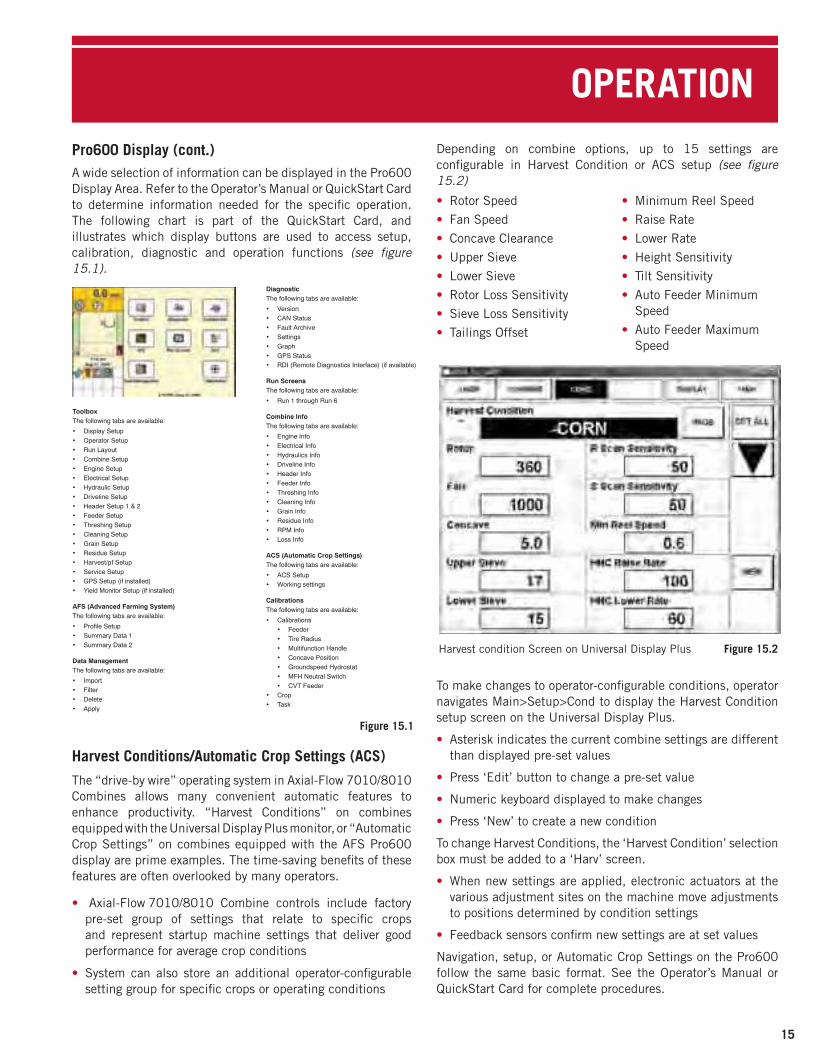
Figure 15.2
• Rotor Speed
• Fan Speed
• Concave Clearance
• Upper Sieve
• Lower Sieve
• Rotor Loss Sensitivity
• Sieve Loss Sensitivity
• Tailings Offset
• Minimum Reel Speed
• Raise Rate
• Lower Rate
• Height Sensitivity
• Tilt Sensitivity
• Auto Feeder Minimum Speed
• Auto Feeder Maximum Speed
Depending on combine options, up to 15 settings areconfigurable in Harvest Condition or ACS setup (see figure 15.2)
To make changes to operator-configurable conditions, operatornavigates Main>Setup>Cond to display the Harvest Conditionsetup screen on the Universal Display Plus.
• Asterisk indicates the current combine settings are different than displayed pre-set values
• Press ‘Edit’ button to change a pre-set value
• Numeric keyboard displayed to make changes
• Press ‘New’ to create a new condition
To change Harvest Conditions, the ‘Harvest Condition’ selectionbox must be added to a ‘Harv’ screen.
• When new settings are applied, electronic actuators at the various adjustment sites on the machine move adjustments to positions determined by condition settings
• Feedback sensors confirm new settings are at set values
Navigation, setup, or Automatic Crop Settings on the Pro600follow the same basic format. See the Operator’s Manual orQuickStart Card for complete procedures.
Harvest condition Screen on Universal Display Plus

Operation and AdjustmentsDraper HeadersAs combine capacity has expanded in recent years, a challengefacing designers and operators was how to satisfy the appetiteof these machines with a grain platform. Sure, heads couldbe made wider, but then they really need to “bend” to followvariations in ground contour. The answer has been the returnof the draper (see figure 16.1).
• In addition, drapers offer exceptionally gentle, smooth crop flow to the feeder, and efficient “heads-first” feeding into the rotor. This all adds up to 20% more capacity and productivity.
• Case IH offers rigid drapers for applications (such as rice) where the head will not be run on the ground, and flex- drapers (for small grains and soybeans) where the head frequently is operated at near ground level
• Flex-drapers are made up of 3 independently floating header sections that allow 13 inches of vertical float at the ends of the header, and 4.8 degrees of lateral float [12 inches at the end of a 30 foot header (see figure 16.2)]
• Split 2-section reel follows header flex to maintain consistent reel-to-knife adjustment for best crop feeding
The header suspension allows complete adjustment. Refer tospecific adjustments found in the Operator’s Manual.
During operation, the operator can make control adjustments:
• Float optimizer (controls ground pressure using automatic height control)
• Hydraulic Guard Angle (controls stubble height and clearance over rocks and ground trash)
Combine Auto Header Height Setting (Float Optimizer)
• Decrease ground pressure if skid shoes are riding heavy, pushing trash
• Increase ground pressure if header is riding up on stubble
• Optimizer gauge indicates the amount of ground pressure
For optimum performance, reel and draper adjustments arecritical:
• Reel position and speed should be set so the reel lightly flicks the crop onto the drapers, while not impeding crop flow across the header. This typically works out to a reel speed about 10% faster than ground speed.
• Draper speed is not dependent on ground speed. Draper speed should be set for a consistent windrow formation entering the combine. Increased draper speed does not equal increased capacity (see figure 16.3).
16
OPERATION
Figure 16.1
Figure 16.2
Figure 16.3

ROTOR SETUPEvery experienced operator knows crop and harvestingconditions vary from season-to-season, and field-to-field.Fine-tuning as harvest progresses will allow you and yourcombine to maximize performance. Several optional rotorelements are available to customize the rotor to best fit specificthreshing and separating needs. The Operator’s Manualprovides complete mounting and setup details, and commonstartup configurations for most crops.
• Non-spiked Rasp Bars are the primary threshing element(see figure 17.1). In addition to providing threshing action,
they also provide positive crop movement through the rotor cage.
• Spiked Rasp Bars are primary material movers (see figure 17.2). The aggressive nature of the spiked bar tears the
crop mat apart, allowing grain to effectively separate from the straw.
In conditions where crop material is tough and may tend to wrap, spiked bars chop the material sufficiently to prevent roping
Spiked rasp bars must always be installed in pairs 180˚ apart to maintain rotor balance
Generally used on the rear half of the rotor
Standard Rotor has non-spiked rasp bars in the front, andeight spiked rasp bars in the rear separator area (see figure 17.3).
Straight Separator Bars are used as a primary separating element. Tend to thin out the crop mat to allow improved separation (see figure 17.4).
Separator bars are installed across two rasp bar mounting pads, and must always be installed in pairs 180˚ apart to maintain rotor balance
Used often in high-yielding corn
Not recommended for green crops
May be removed if rotor is consuming excess power
Helical Kicker Bars are used as a primary crop moving element
Used at the rear of the rotor, conforms to helical pattern of rasp bars (see figure 17.5)
Helical kickers are installed across two rasp bar mounting pads, and must always be installed in pairs 180˚ apart to maintain rotor balance
Two kickers at the rear of the rotor should not be removed
Additional helical kickers can be used over the front and center separator grates if separation is not required (see
figure 17.6)
OPERATION
17
Figure 17.1
Figure 17.2
Figure 17.4
Figure 17.6
Figure 17.3
Figure 17.5

18
OPERATIONROTOR SETUP (cont.)
ROTOR MODULESThe rotor cage is made up on several fixed and removableelements. The rotor modules form the lower 180˚ wrap aroundthe rotor, above the grain pan. Eight modules, in four pairs, canbe “mixed and matched” as necessary to precisely adapt thethreshing and separation effect of the Axial-Flow 7010/8010Combine to virtually any operating condition. When properlyconfigured, approximately 100% of threshing and 90% ofseparation should occur in the front half of the rotor cage area.
• Modules are identified by their position, such as ”1R” for the right front, and “4L” for the left rear module (see figure
18.1)
Left-hand modules measure 21 3/4", and are marked with an “L” at reference 1
Right-hand modules measure 22 1/2", and are marked with an “R” at reference 1
Modules must be leveled relative to the rotor. See specific instructions in the Operator’s Manual, or contact your Case IH dealer
MODULE TYPESSmall Wire (see figure 18.2)
• 3/16" wire spaced 3/16" apart
• Used for small grain crops
Large Wire (see figure 18.3)
• 1/4" wire spaced 1/2" apart
• Used for corn, soybeans and rice
Slotted (see figure 18.4)
• Has slots approximately 1" X 1 1/2" instead of wires
• Used mainly for edible beans and sunflowers
Round Bar (see figure 18.5)
• 16mm round bars spaced 16mm apart, oriented parallel toaxis of the rotor
• Used primarily to reduce “hair pinning” of material in crops such as high-moisture corn
Large Skip Wire (see figure 18.6)
• Every-other wire removed from standard large wire module
• Mainly used in separator area
• Can remove all wires to make a “keystock” module
• In corn, no fewer than every-other wire should be used, to prevent cobs from being thrown down and damaging upper sieve
Solid Module (see figure 18.7)
• Can be used in very easy threshing and separating crop
• Prevents excess trash from overloading cleaning system
Figure 18.2 Figure 18.3
Figure 18.4 Figure 18.5
Figure 18.6 Figure 18.7
Figure 18.1
FINE-TUNING SEPARATIONOnce the crop is threshed, approximately 10% of the grainnormally remains mixed in with the straw material mat thatmoves through the rotor cage.
• Separation is controlled primarily by the selection of rotor modules used, and the speed at which material moves through the cage.
• Refer to suggested module orientation and material speed factors in the Operator’s Manual for typical crop setup
Crop speed is determined by 4 basic factors:
• Rotor Speed
• Concave Clearance
• Cage Transport Vane Position
• Number of Straight Separator Bars
The angle of cage transport vanes can be adjusted to control therearward movement of crop material.
• Moving the bottom of the vane rearward speeds up crop flow
• Moving the bottom of the vane forward slows crop flow

OPERATION
19
OPTIMIZING STRAW QUALITYThegrain-on-grain and rubbingnature of theAxial-Flowcombinethreshing and separating system can inherently reduce strawlength, making baling straw challenging in some conditions.Some specific settings, and harvesting conditions can beimplemented to help produce longer length and quality straw.Special settings will tend to reduce threshing and separatingperformance, so a balance of straw value and grain loss mustbe determined when making adjustments.
Reduce aggressiveness of rotor and move material through the rotor cage quickly:• Standard rotor—do not use spiked rasp bars unless absolutely necessary for complete threshing.
• Reduce rotor speed and relax the concave, but maintain threshing and separating performance.
• Adjust transport vanes over separator grates to the fast position
• Adjust transport vanes over the concave to the mid or fast position
Configure rotor cage for smoother material flow:• Use small wire concaves, or at a minimum, in the No.1 left and No. 1 right concave positions
• If grain loss is not an issue, use solid separator grates in the second and third positions
Other machine settings:• Use a combine with discharge beater instead of straw chopper
• Lower chopper/beater pan to the “Corn” position
• Retract the straw chopper concave and/or reduce chopper/ beater speed
Harvesting conditions:• Harvest when straw is tough during damp, tough conditions such as early morning or late evening.
• Cut stubble lower; for more stem than normal
EVALUATING GRAIN LOSS AND COMBINE PERFORMANCEIt’s harvest-time, and the return on a season’s investment in labor, land, fertilizer, herbicide and pesticides all lies with thecombine’s ability to put every kernel in the grain tank ... a tall order, and in reality-impossible. But the Axial-Flow Combines fromCase IH will get you closer to perfection than any other combine.
Some simple steps should be taken as the combine is adjusted to match each crop and season. Check the cutting, threshing andseparating performance of the combine, and isolate where adjustment may be necessary to get the best possible sample in thetank, with minimal loss.
A structured method of determining the source of loss is essential prior to making any adjustment to reduce loss. The illustrationbelow demonstrates how to make an accurate assessment of the source of harvest loss.The number of seeds counted in each area indicated represents loss in various stages of harvest:Area A: Pre-harvest loss in standing crop, prior to contact with the reel.Area B: Pre-harvest + Header loss. (Header loss = B – A) Loss occurring at the header due to shattered, dropped heads.Area C: Pre-harvest + Header + Separator Loss. (Separator loss = C – B – A) Separator loss will not be isolated to the rotor or cleaning system.
Back up approximately one combinelength. Safely stop the combine, andperform seed loss evaluation.
Remove straw spreaders. Enter an average area of the field, away from edges. Harvest a full swath, at normaloperating speed. Travel a minimum of two combine lengths into the field after the machine is full and deliveringgrain to the grain tank. Stop ground travel and the separator.

20
OPERATIONIsolating Separator LossSeparator loss can be isolated to rotor or cleaning system lossin either of two ways.
1. Note the current chaffer and sieve settings. Open shoe and chaffer sieves fully, and repeat the test as illustrated. If observed separator loss is unchanged, loss is coming from the rotor. If loss decreases, observed loss from first test was from the cleaning system.
2. Perform the initial test with straw spreaders installed. Made sure the separator has stopped before backing away from cut crop. Observed loss in Area “C” is from the sieves (cleaning system). Observed loss in Area “D” is rotor loss that was spread across the width of the machine by the straw spreaders.
Determine the amount of loss at each source.The next step is to count the grains lost on the ground in each“counting area.” Each “counting area” should be equal toabout 10 square feet.
To convert the amount of loss you find at any point to bushels,refer to the seed loss tables in your Operator’s Manual. Lossesshould be checked in several areas and averaged to eliminatethe effects of any uneven feeding.
Make the proper adjustments.Once the loss counts have been performed as described,required areas of attention will be identified.
• To reduce header losses, make sure header is adjusted properly as explained in the Operator’s Manual
• Before making adjustments for separator losses, be sure there are no grain leaks due to missing bolts, open clean out doors, or other obvious causes
• For adjustments to the rotor and cleaning system, see your Operator’s Manual
• The most important detail in combine adjustment is toMAKE ONE ADJUSTMENT, THEN TEST THE OUTCOME.This allows only the effect of that adjustment to be analyzed.Making multiple adjustments between tests does not give a clear indication of which adjustments are positive, and others that may have negative results.
“Power-Stall” Problem Diagnosis (Quick Stop)Problems with internal components are difficult to analyze.If you’re losing grain at the separator, you may want to use the“power-stall” diagnostic method.
• The “power-stall” uses an approved method of stopping the separator quickly while harvesting
• By preventing the separator from emptying, as would be the case in a normal shutdown, this procedure allows inspection of the inside of the combine as if it were in operation (see
figure 20.1)
• There will be some major differences between the conditions observed and those that exist during operation. Even with these obvious limitations, the procedure can be an extremely useful diagnostic “tool.”
• Refer to the Operator’s Manual under the heading “Quick Stop” Problem Diagnosis for a description of the procedure.
Figure 20.1

TROUBLESHOOTING
21
Performance Concern Possible Cause CorrectionMaterial backfed by the feeder chain Feeder chain mis-adjusted
Rotor lugs worn, too far from feeder
Adjust feeder chain
Replace rotor lugs
Grain not properly threshedfrom heads
Rotor speed too slow
Clearance between rotor and concave too wide
Not enough material entering combine for properthreshing
Crop not ripe
Difficult threshing crop
Rasp bars or concave damaged, bent or wornexcessively
Losing RPM because of sluggish or malfunctioningengine governor
Increase rotor speed
Reduce concave clearance
Lower head and/or increase ground speed
Wait until crop is ready for harvest
Re-install concave wires if removed. Move cage vanesto slower position.
Inspect all rasp bars and concave for excessive wearor damage
Check or change fuel filters
Have engine performance evaluated by dealertechnician
Rotor blockage Rotor speed too slow
Irregular feeding
Crop too wet or not ripe
Beater/chopper drive belt slipping
Increase rotor speed
Adjust head and feeder for optimum feeding
Wait until crop is ready for harvest
Check belt tension and tighten, if necessary
Excessive cracked grain in tank Clearance between rotor and concave too small
Rotor speed too high
Not enough material entering combine
Excessive tailings
Concave clogged
Grain being cracked in elevator
Uneven feeding, wads entering rotor
Increase concave clearance
Reduce rotor speed and/or open concaves slightly
Lower head and/or increase ground speed
See “Excessive tailings” section
Clean concave
Adjust grain elevator chain tension
Adjust feeder chain. Check feed auger height andretractable finger adjustment.
Grain loss over rotor Rotor speed too slow. Crop bunching in rotor.
Incomplete threshing
Concave blocked allowing excessive grain to bepassed to separator sections of the rotor
Crop too wet or contains excessive green material
Increase rotor speed
Decrease concave clearance
Clean concave and separator grates thoroughly
Wait until crop is ready for harvest
Grain is not properly cleaned Insufficient air flow from cleaning fan
Rotor speed too high, and/or insufficient concaveclearance, resulting in broken crop debris (trash)overloading the sieves
Pre-sieve and/or top sieve opened too wide,allowing excessive trash to fall onto bottom sieve
Incorrect concave or grate module type for crop orcondition
Bottom sieve opening too wide, allowing trash toenter clean grain
Bottom sieve overloaded or blocked
Increase fan speed to the point grain is being cleanedproperly, but not blown over the rear of the sieves
Re-adjust rotor speed and concave clearance sothreshing is complete without excess trash
Close top sieve so only the clean gain falls onto thebottom sieve and most of the trash is discharged fromthe machine from the rear of top sieve. Grain will alsobe thrown over with trash if the sieve is closed too far.
Change to more suitable module(s)
Reduce bottom sieve opening
Clean sieves, if necessary
Grain loss over the sieves Too much air flow from the cleaning fanConcave too tightRotor speed too highTop sieve not opened wide enough or blocked
Bottom sieve not opened wide enough or blocked,causing excessive grain to enter tailings and bere-threshed
Reduce air flow with variable speed fan control.Lower concaveDecrease rotor speedOpen the top sieve so that all clean grain moves to thebottom sieveOpen the bottom sieve and clean sieve if blocked

22
TROUBLESHOOTING
Performance Concern Possible Cause CorrectionGrain loss over the sieves (cont.) Cleaning shoe drive belt slipping
Cleaning shoe not level
Incorrect concave or grate module, especially in #1or #2 positions
Adjust cleaning shoe belt tension
Re-calibrate self-leveling shoe. Check electric control. Contact Case IH dealer for assistance.
Change to more suitable module(s) for crop beingharvested
Excessive tailings Insufficient air flow from cleaning fan (excessivematerial falling through top sieve)
Bottom sieve closed too much, or blocked
Overthreshing
Incomplete tailings processing of unthreshed crop
Excessive air flow from cleaning fan (grain blownfrom bottom sieve into tailings)
Cleaning shoe drive belt slipping
Increase air flow with variable speed fan control
Open bottom sieve slightly and clean thoroughly,if blocked
Reduce rotor speed and/or increase concave clearanceto prevent straw from breaking excessively
Install special tailings auger doors
Reduce air flow with variable speed fan control
Check cleaning shoe drive belt tension
Sieves overloaded Insufficient air flow from cleaning fan
Over threshing
Top sieve open too wide, or blocked
Cleaning shoe drive belt slipping
Incorrect concave or grate module type, allowingexcess separation
Increase fan speed
Reduce rotor speed and/or increase concave clearanceto reduce amount of short straw on top sieve
Close sieve slightly and clean thoroughly, if blocked
Check all drive belts and adjust tension as required
Change to more suitable module(s) for crop beingharvested
Residue ManagementLarger combines, bigger headers and higher yielding cropsmean a high volume of material is flowing from the back ofyour combine. The need to distribute residue evenly is crucial. Uneven soil drying and warming, and excess residue cover canrestrict the emergence of the next crop (see figure 22.1).
The residue management (spreader) can be operated in threedifferent modes:
• Standard—spreads chaff and straw
• Windrow straw, spread chaff
• Windrow straw and chaff
See the Operator’s Manual for the configuration of the spreader,straw deflector door and chaff pan for each of the operatingmodes.
• A hydraulic control valve is used to vary the spreader speed to match header width and residue volume for the best spreading performance
• Deflectors and spreader fingers can be adjusted to vary distribution pattern
The straw chopper can be operated in two speeds to achievethe desired level of residue size reduction.
• Stationary knives can be added to assist in chopping straw. Adjustment handle changes aggressiveness of cutting (see
figure 22.2).
• Single (coarse cut), or double (fine cut) knives
• Adjustment handle must be moved up to remove the knives when operating in corn
Figure 22.1
Figure 22.2

AFS
AFSThere are two kinds of power that enhance productivity intoday’s agriculture-the power you find in new, modernequipment, and the power of information you harness with CaseIH AFS Precision Farming systems. Harvest data is reported tothe operator on either of two touchscreen displays.
Universal Display Plus• 8010 - 2006 and earlier
Pro600• 8010 - 2007 and later
• 7010 - 2007 and later
Five basic components work together to capture harvestinformation as the combine moves through the field.
• The flow sensor measures grain volume
• The moisture sensor measures the grain moisture and temperature
• A ground speed sensor and programmed header width determine coverage area
• The yield monitor combines all crop and area data to populate the touchscreen display with instantaneous and historical yield information in terms of dry bushels per acre
• Information is stored on a memory card that transfers data to desktop software, helping you manage your farming operation, using the outcome of your past year’s crop in future cropping plans
• Add a DGPS receiver and record a data point every 1, 2, or 3 seconds as you travel through the field, to fully realize the power of information
If not used correctly, a tool’s full potential is seldom realized.With that thought in mind, some simple guidelines may helpyou make AFS operation simple and second nature, meetingthe full potential you expect from your investment.
Some simple adjustments and maintenance, as well asconscientious component calibration are necessary to assureaccuracy.
To understand the need for system calibration, consider AFSoperates using electronic components that translate groundspeed, header position, grain moisture and grain volume datainto electrical signals.
• Many variables would make “set-at-the-factory” accuracy impossible. The operator must calibrate the system once in the field, using scales and moisture testers with known accuracy to verify the weight and moisture of the grain.
• The operator manually enters the actual numbers. The AFS system makes adjustments so future harvest data, as well as the calibration load and prior harvest data, accurately reflect the moisture and weight of the grain being harvested.
System inputs that require calibration:
• Header stop height (turns counting on and off)
• Distance (used to calculate ground speed)
• Grain Temperature
• Grain Moisture
• Grain Weight
Grain Moisture and Weight CalibrationThe most common calibration necessary is crop calibration—moisture and weight. Prior to harvesting, some mechanicalchecks should be performed.
• The distance between the clean grain elevator paddles in the elevator head and the flow sensor impact plate is fixed. Adjustment of the elevator chain tension moves the sensor with the elevator head shaft to maintain the correct relationship (see figure 23.1).
• The flow sensor impact plate should be inspected. If any holes are worn through the plate it should be replaced.
Record the sensor calibration number from the decal on thesensor housing (see figure 23.1) . This number is entered inthe touchscreen display during combine “Vehicle Setup.”
1. Clean Grain Elevator2. Bypass Housing3. Bypass Auger Housing4. Moisture Sensor
23
Figure 23.1
Figure 23.2

24
AFSGrain Moisture and Weight Calibration (cont.)The grain moisture sensor operates on the principle of anelectrical current flowing from the sensor fin, through the grain,to ground (see figure 23.2).
• The grain moisture sensor fin and temperature sensor must be clean for proper function. A buildup of crop sap can reduce sensor accuracy.
• Remove any crop residue by scraping, using soap and water, or solvent to clean the moisture fin and temperature sensors
The bypass auger is controlled by a proximity switch that cyclesthe auger as required, to assure the sensor fin is always incontact with grain.
• The bypass auger should be removed and cleaned. Ensure the auger has not seized to the plastic block that supports the non-drive end
Operators should monitor Instantaneous Moisture values whileharvesting to confirm the sensor is functioning. If moisturevalues do not show some fluctuation, a problem may exist withthe moisture sensor that requires attention to assure accurateharvest data.
• If moisture readings are consistently very low, the auger may be operating constantly, preventing grain contact with the fin. (Likely to occur only in lower yield crop where the bypass auger removes grain from the bypass as quickly as it enters).
• Your Case IH dealer should be consulted to correct the condition
• If moisture readings are consistent, but at a value more likely to be representative of actual grain moisture content, the auger may not be operating
• The sensor is merely providing a moisture reading of a static sample that is in the bypass housing
• The auger should operate for 30 seconds after the separator is disengaged, to clean grain from the bypass. Auger operation can be checked by visually watching the end of the auger shaft during this 30 second period, to see if the shaft is turning.
• If not, check to assure the moisture sensor bypass auger fuse is not blown. If the fuse is not at fault, contact your Case IH dealer for assistance.
Operators must also remember adjustment or replacement ofany component affecting calibration, requires re-calibration.
• Memory management features of AFS allow operators to apply calibration values to specific loads, or beginning at a specific time during harvest, such as the time when component replacement occurred
• Refer to the Operator’s Manual after re-calibration to use the correct Utility menu to apply calibration to the correct harvest data
To record harvest data, four criteria must be met.
• A memory card must be inserted in the top slot of the display before turning the power ON. The card should have only ONE *.yld file or ONE *.cnh folder. Use Windows Explorer to confirm.
• The clean grain elevator must be running between 250 and 599 RPM
• Ground speed must be registered
• The header must be lowered below the header cut “stop height” position
When data is being recorded, the “REC” indicator on the displaywill be darkened.
In understanding the calibration process, the operator willrealize the importance of maintaining an accurate record ofthe calibration load weight and moisture test results, as well asload identification.
• Identification is necessary to enter a load name into AFS, as well as on scale tickets. The operator should anticipate the need for load names, and can actually enter load names prior to harvest. See the calibration record table included in
the AFS Operator’s Manual.
Do not attempt to make the first load harvested a calibration load. • Frequent stops and starts as harvest begins and the machine is adjusted will result in inaccurate calibration. Once calibration is performed, calibration values can be applied to the initial loads harvested prior to calibration.
• Do not harvest calibration loads until headlands are harvested
• Prior to harvesting the calibration load, make sure the grain tank and truck, cart or trailer used to transport the calibration load is completely empty. Attempt to harvest calibration loads of nearly the same size for best accuracy. Loads of at least 10,000 lb. are suggested.
• Be sure to select a new load prior to harvesting any of the crop to be used for calibration.
• Empty the load into the truck or trailer. IMMEDIATELY select a new load after unloading. Failure to change loads will add to the original calibration load, and will lead to high calibration errors.
• Do not unload on-the-go when harvesting calibration loads
Crop Type: Date:
Combine: Operator
Field Load FlowBu./Hr.
EstimatedWeight
ActualWeight
%Error
Include?(Y/N)
1 Cal 1Hi
2 Cal 2Hi
3 Cal 1Med
4 Cal 2Med
5 Cal1 Lo
6 Cal 2Lo
7
AFS
25
Grain Moisture and Weight Calibration (cont.)More than one calibration load is suggested, using a range ofspeeds and throughputs that are expected in normal operation. Harvest at least four calibration loads for each crop (6-8 isrecommended).
• The objective is to “teach” the flow sensor how different flow rates “feel” to the sensor
• The high output rate should be near that which the operator would prefer to operate the machine
• Medium and low rates are also suggested since variations in yield throughout the field, or conditions that result in reduced ground speed, can periodically lower throughput during normal harvest
• A medium flow rate is 30% less than the high flow rate. A low flow rate is 30% less than the medium flow rate. Example: If the maximum observed flow – instant dry bu. is 2,000 bu./hr. on the display this is considered the high flow rate. The medium flow rate would be 1400 bu./hr. and the low flow rate would be 800 bu./hr. Reduced flow rates are achieved by driving slower or taking a reduced swath.
• The operator should attempt to maintain a consistent flow rate when harvesting each of the loads. Use the “Instantaneous Flow-Dry” display to monitor throughput.
• Take 4-5 moisture tests in each load. Use the average value as the “Actual” moisture reading.
Basic Steps for Successful AFS OperationPreparations to Start Harvesting:
• Install Data Card into Display before powering up the system
• Check time, date and units of measure
• Select correct combine model
• Enter grain flow sensor calibration number
• Set up Grower, Farm, Field and Task (Load) structure
• Select Crop Type selection
• Select % Crop Trade Moisture
• Select Crop Trade Weight
• Associate Header Type and Size
• Set Header Stop Height
• Set Header Alarm
• Set GPS Configuration and Logging Interval
• Perform Distance Calibration
• Harvest Calibration Sample
• Calibrate Moisture Sensor
• Harvest Calibration Loads at varying throughput rates
• Calibrate Yield Sensor
• Repeat Calibration for each Crop Type
An understanding of these basics is essential in achievingaccurate AFS data records. The AFS Operator’s Manual forHarvesting Operations provides step-by-step and detailedinstructions for performing AFS operations, calibrations andmanaging the display information and harvest data.
• Follow instructions to “Apply Cal Values” as necessary to loads harvested prior to calibration.

26
STORAGE
Combine StorageWhen harvest is done, and you’ve worked long hours for weeksto bring in the harvest, it is real easy to want to take sometime off, or if the conditions are right, get out and do some falltillage before the snow flies. But, just make sure to give yourcombine some end-of-season and pre-storage attention beforethe shed doors close, and it’s forgotten until next harvest season.Off-season neglect can cost big in terms of corrosive damage,rust and deterioration, all avoidable with a little thought toprevention and maintenance.
The combine should be stored in a dry, protected location. Outside storage, subject to weather and elements will shortenthe life of the machine.
The following procedure should be used to prepare the combinefor storage periods of up to 6 months.
1. Remove the header to make cleaning and inspection easier and more thorough.
2. The combine should be thoroughly cleaned before storage to remove chaff and debris that can collect moisture or attract rodents during storage.
• A high volume and velocity air blower like a leaf blower or industrial compressor works best when debris is dry
• Washing the unit will provide the most complete cleaning, removing debris that may be stuck to grease or oily accumulations that cannot be removed with just compressed air or mechanical cleaning; as well as removing the grease and oil as well
• High pressure spray should not exceed 870 PSI and 140˚F. Keep the spray wand at least 11 inches away from the combine surfaces.
• If the unit is washed, care must be exercised to assureCOMPLETE removal of chaff and debris, especially from
inconspicuous areas where it will result in accelerated rust and corrosion over an extended period of time
• Avoid directing a high pressure water stream toward bearings, seals, oil reservoirs, gearboxes, fuel tank fill, electrical equipment, engine exhaust, air filters and the cab interior
• Do not direct a high pressure water stream directly perpendicular to bearings and seals. Angling the stream reduces the possibility of water infiltration through seals. The Operator’s Manual lists complete precautions for cleaning with high pressure water.
• Open removable covers, doors or plugs that allow water to drain from the transition cone, auger troughs or grain tank
3. Clean the inside of the machine including the concave and separator grate, chaffer and shoe sieves, cleaning fan, clean grain and tailings auger troughs
• Open the clean grain and tailings elevator doors
• Spray the sieves with a rust preventive
4. Clean the inside of the cab and instrument panel. Clean the cab air and recirculation filters.
5. Rodents can damage a combine while in storage. Rodents will eat plastic, insulation or rubber materials, especially when coated with grain dust.
• Clean the areas where rodents may nest
• Leave access panels and doors open to remove convenient nesting pockets. In some conditions, leaving mothballs will help discourage rats and mice.
6. After thoroughly cleaning the combine and allowing it to dry, lubricate the machine as specified in the “Lubrication/ Filters/Fluids section of the Operator’s Manual.
7. Run the engine long enough to completely warm the oil in the crankcase before draining the oil.
• Remove and replace the oil filter as instructed
• Fill the crankcase with fresh oil and run the engine for two to five minutes
8. Open the drain on the water separator fuel filter and drain water and sediment.
• Fill the fuel tank with a premium grade diesel fuel. If this fuel grade has not been used regularly, drain the fuel tank and fill with premium diesel fuel. Do not store the combine
with bio-diesel fuel in the tank or fuel system.
• Run the engine for five minutes to circulate the fuel through the fuel injection system
• Close the fuel shut-off valve between the water separator filter and fuel tank to prevent fuel draining from fuel injection system into the fuel tank
8. Clean the air cleaner filter and body.
9. Check coolant anti-freeze protection. Use only low silicate, heavy-duty coolant in the cooling system.
• Check cooling system conditioner level and add conditioner if necessary
10. Use compressed air or water under pressure to thoroughly clean the radiator and other cooling elements. Do not direct high pressure water at an angle to cooling fins, as fins may be bent and damaged.
11. Cover the engine breather pipe and exhaust pipe.
12. Batteries can remain in the combine, but must be fully charged to prevent freezing in cold temperatures.
• Remove the battery ground cables to prevent slow discharge
13. Store the combine out of direct sunlight. Clean tires before storage, and support the combine on blocking if possible to remove load from the tires.
• If the combine is not blocked, check tires frequently and maintain inflation during storage

ADJUSTMENT SLIDE RULE
PM-13000Front
PM-13000Back
14. Lubricate chains with light oil or chain lubricant
15. Lower the head to remove load from the hydraulic system
• Retract all hydraulic cylinders if possible. Coat exposed cylinder rods with grease to prevent rust and corrosion (clean grease from rods when removing the combine from storage).
16. Remove tension from belts.
17. On combines equipped with Moisture Sensor, remove the bypass auger and remove grain from the housing. Make
sure the auger turns freely in the plastic bearing block. Use the retaining pins to reach through the bearing block to align and hold the auger in place while re-installing the block.
Removing the Combine from StorageConsult the Operator’s Manual. In addition to confirming fluidlevels and closing clean out doors, several other inspectionsare suggested when preparing the combine for use.
Combine Separator Adjustment Slide RuleHow the Slide Rule works:Identify the symptom you have, line up the slide rule with the symptom, and read the suggested adjustments in order of priority.
Why:To achieve maximum productivity from your Case IH combine.
When:The slide rule is a useful tool to make initial machine settings, and in-field adjustments to set the combine for maximumproductivity.
Slide rules cover most common crops, and fit easily in the buddy seat compartment to be readily available when needed. It is easyto read, easy to follow and gives step-by-step instruction to improve combine performance.
27

• Visit www.caseih.com/na
• Click on Search for Parts under Parts & Service
• Enter your model number or product name
• View a parts list and diagram
• Build a list of the parts you need
• Contact your Case IH dealer to order parts
Safety Never Hurts!™ Always read the Operator’s Manual before operating any equipment. Inspect equipment before using it, andbe sure it is operating properly. Follow the product safety signs, and useany safety features provided.
Case IH and CNH Capital are registered trademarks of CNH America LLC.Any trademarks referred to herein, in association with goods and/orservices of companies other than CNH America LLC, are the property ofthose respective companies.
CNH America LLC reserves the right to make improvements in design andchanges in specifications at any time without notice and without incurringany obligation to install them on units previously sold. Specifications,descriptions and illustrative material herein are as accurate as known attime of publication, but are subject to change without notice.
This literature has been published for worldwide circulation. Availabilityof some models and equipment builds varies according to the country inwhich the equipment is used.
PM-13955 Issued 5/07 Replaces: None © 2007 CNH America LLC. All rights reserved. Printed in U.S.A. www.caseih.com/na

Thank you very much
for reading.
PLEASE CLICK HERE. Then back to the site.
At the bottom of the
page,
free add to card.
Then get more free
information


