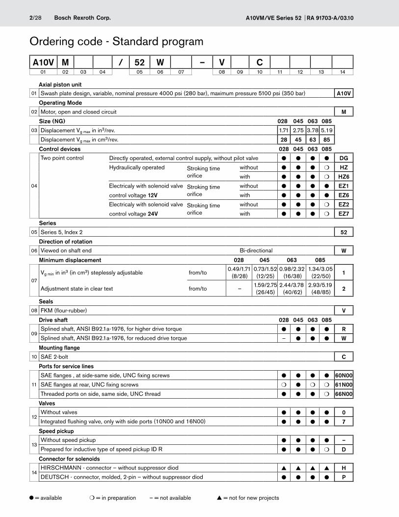
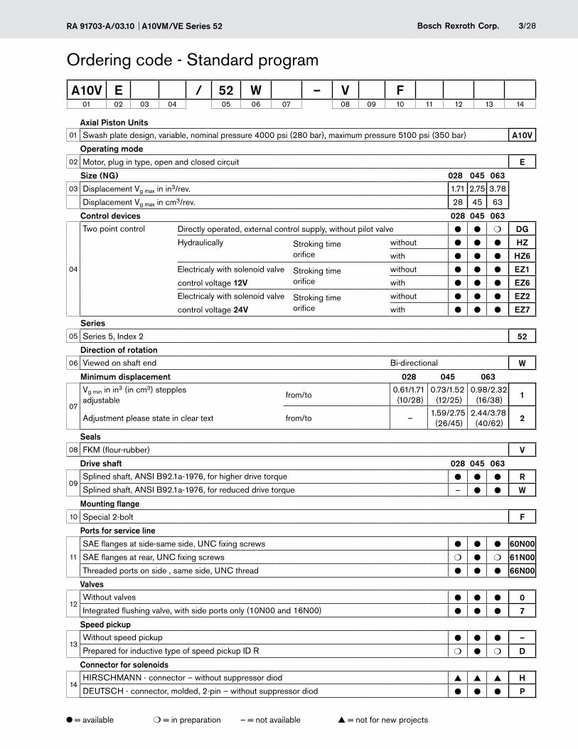
Linear Motion and Assembly Technologies Service Pneumatics Hydraulics Electric Drives and Controls Series 52 Size 28 to 85 Nominal pressure 4000 psi (280 bar) Maximum pressure 5100 psi (350 bar) Open and closed circuit Features Dual displacement motor, axial piston swashplate design, - for hydrostatic transmissions in open and closed circuits Output speed is directly proportional to inlet flow and inver- - sely proportional to motor displacement Output torque increases proportional to the pressure diffe- - rence between high and low pressure sides and increasing displacement Heavy duty bearings for long service life - High permissible output speed - Well proven A10-rotary unit technology - High power/weight ratio – compact dimensions - Low noise - External control pressure supply possible - Minimum displacement can be set externally - SAE-2-bolt mounting flange on A10VM - Special 2-bolt mounting flange on A10VE - RA 91 703-A/03.10 1/28 Replaces: 11.07 Axial Piston Variable Motor A10VM Plug-in Version A10VE Data sheet Contents Technical Data 4 Two-point direct control DG 7 Two-point control, hydraulically operated HZ/HZ6 8 Two-point control, electrically operated EZ 9 Dimensions size VM 28 to 85 10 Dimensions size VE 28 to 63 18 Integrated flushing and boost pressure relief valve, N007 24 Connector for solenoids 25 Electronic controls 25 Speed pickup 26 Mounting position 27 General instructions 28 A10 VE A10 VM
Transcript
Linear Motion andAssembly Technologies ServicePneumaticsHydraulics
Electric Drives and Controls
Series 52 Size 28 to 85Nominal pressure 4000 psi (280 bar)Maximum pressure 5100 psi (350 bar)Open and closed circuit
FeaturesDual displacement motor, axial piston swashplate design, -for hydrostatic transmissions in open and closed circuits
Output speed is directly proportional to inlet flow and inver- -sely proportional to motor displacement
Output torque increases proportional to the pressure diffe- -rence between high and low pressure sides and increasing displacement
Heavy duty bearings for long service life -
High permissible output speed -
Well proven A10-rotary unit technology -
High power/weight ratio – compact dimensions -
Low noise -
External control pressure supply possible -
Minimum displacement can be set externally -
SAE-2-bolt mounting flange on A10VM -
Special 2-bolt mounting flange on A10VE -
RA 91 703-A/03.10 1/28 Replaces: 11.07Axial Piston Variable Motor A10VM
Maximum pressure pmax ________________________ 5100 psi (350 bar) With motors connected in series please consult us.
Case drain pressure
Max. permissible pressure at leakage port L
pabs max operation as a motor in open circuit 58 psi (4 bar abs) pabs max operation as a motor in closed circuit 58 psi (4 bar abs) pabs max motor/pump operation in open circuit 29 psi (2 bar abs)
Direction of rotation
Direction of rotation, viewed on shaft end
clockwise counter-clockwise
B to A A to B
Adjustment of displacement
The minimum displacement is steplessly adjustable within the range of the screw lenghts 1 or 2 (see ordering code).
Please state minimum displacement in clear text when ordering.
Selection diagram
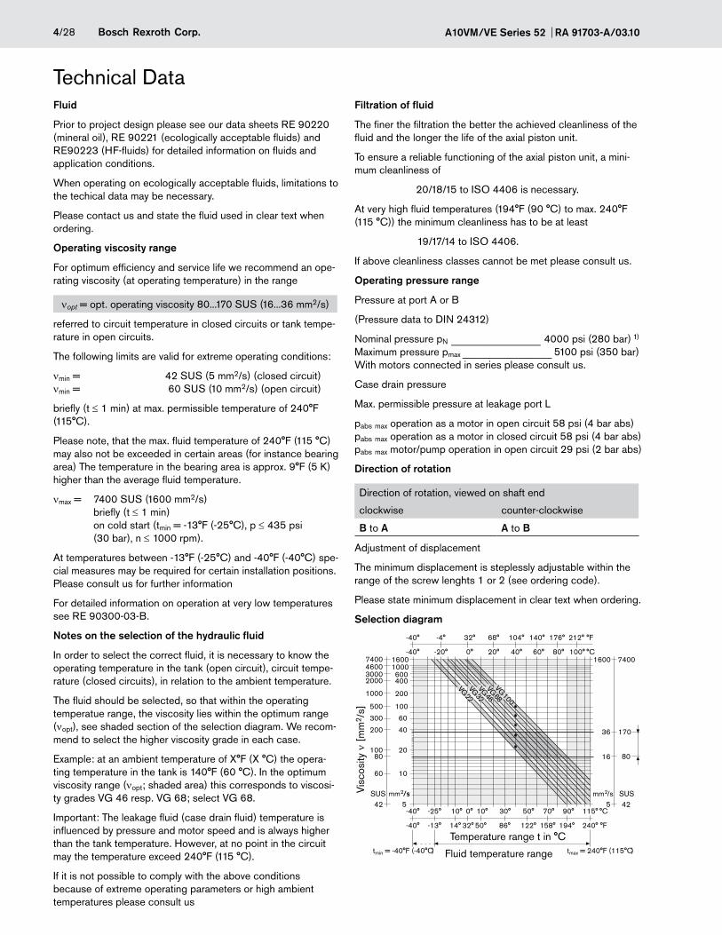
Fluid
Prior to project design please see our data sheets RE 90220 (mineral oil), RE 90221 (ecologically acceptable fluids) and RE90223 (HF-fluids) for detailed information on fluids and application conditions.
When operating on ecologically acceptable fluids, limitations to the techical data may be necessary.
Please contact us and state the fluid used in clear text when ordering.
Operating viscosity range
For optimum efficiency and service life we recommend an ope-rating viscosity (at operating temperature) in the range
nopt = opt. operating viscosity 80...170 SUS (16...36 mm2/s)
referred to circuit temperature in closed circuits or tank tempe-rature in open circuits.
The following limits are valid for extreme operating conditions:
nmin = 42 SUS (5 mm2/s) (closed circuit) nmin = 60 SUS (10 mm2/s) (open circuit)
briefly (t ≤ 1 min) at max. permissible temperature of 240°F (115°C).
Please note, that the max. fluid temperature of 240°F (115 °C) may also not be exceeded in certain areas (for instance bearing area) The temperature in the bearing area is approx. 9°F (5 K) higher than the average fluid temperature.
nmax = 7400 SUS (1600 mm2/s) briefly (t ≤ 1 min) on cold start (tmin = -13°F (-25°C), p ≤ 435 psi (30 bar), n ≤ 1000 rpm).
At temperatures between -13°F (-25°C) and -40°F (-40°C) spe-cial measures may be required for certain installation positions. Please consult us for further information
For detailed information on operation at very low temperatures see RE 90300-03-B.
Notes on the selection of the hydraulic fluid
In order to select the correct fluid, it is necessary to know the operating temperature in the tank (open circuit), circuit tempe-rature (closed circuits), in relation to the ambient temperature.
The fluid should be selected, so that within the operating temperatue range, the viscosity lies within the optimum range (nopt), see shaded section of the selection diagram. We recom-mend to select the higher viscosity grade in each case.
Example: at an ambient temperature of X°F (X °C) the opera-ting temperature in the tank is 140°F (60 °C). In the optimum viscosity range (nopt; shaded area) this corresponds to viscosi-ty grades VG 46 resp. VG 68; select VG 68.
Important: The leakage fluid (case drain fluid) temperature is influenced by pressure and motor speed and is always higher than the tank temperature. However, at no point in the circuit may the temperature exceed 240°F (115 °C).
If it is not possible to comply with the above conditions because of extreme operating parameters or high ambient temperatures please consult us
Technical Data
-40° -4° 32° 68° 104° 140° 176° 212° °F
-40° -20° 0° 20° 40° 60° 80° 100° °C
-40° -25° 10° 0° 10° 30° °C50° 70° 90° 115°
-40° -13° 14° 32° 50° 86° °F122° 158° 194° 240°
160074001000460060030004002000
2001000
100500
60300
40200
20100
1060
mm2/sSUS542
80
74001600
17036
8016
425SUSmm2/s
tmax = 240°F (115°C)tmin = -40°F (-40°C)
VG 22VG 32VG 46VG 68VG 100
Temperature range t in °C
Fluid temperature range
Visc
osity
n [
mm
2 /s]
5/28Bosch Rexroth Corp.RA 91703-A/03.10 A10VM/VE Series 52
Technical DataTable of values (theoretical values, without efficiency levels and tolerances; values rounded)
Size 28 45 63 85
Displacement Vg max in3 (cm3)
1.71 (28)
2.75 (45)
3.78 (62)
5.31 (87)
Vg min in3 (cm3) 0.49 (8) (VM) 0.61 (10) (VE)
0.73 (12) 0.98 (16) 1.34 (22)
Speed1)
max. at Vg max n0 max rpm 4700 4000 3300 3100
max. at Vg min n0 max zul rpm 5400 4600 3900 3560
Min. speed in cont. operation n0 min rpm 250 250 250 250
1) At max. speed in closed circuit operation make sure that motor outlet pressure is at least ≥ 18 bar. 2) in open circuit ∆p 4000 psi (280 bar) at pboostpress. 30 psi (2 bar) in closed circuit ∆p 3700 psi (260 bar) at pboostpress. 290 psi (20 bar)
Minimum required outlet pressure (low pressure) at port A (B) depending on motor speed
0
5
10
15
20
25
0barpsi
75
145
220
290
365
0.8 0.9 1 1.1 1.2
Motor speed n/nmax
Out
let p
ress
ure
p HD [
bar] permissible
range
A10VM/VE Series 52 RA 91703-A/03.106/28 Bosch Rexroth Corp.
Technical dataCalculating size
Flow qV =Vg • n
[gpm]Vg = geometric displacement per rev. in in3
231 • hV ∆p = Differential pressure in psi
Torque T =Vg • ∆p •hmh
[Nm]n = speed in rpm
24 • p hV = volumetric efficiency
hmh = mechanical-hydraulic efficiency
Output power P =T • n
=qV • ∆p • ht
[kW]ht = Total efficiency (ht = hV • hmh)
5252 1714 TK = Torque constant
Output speed n =qv • 231 • hv
[min-1]Vg
Flow qV =Vg • n
[L/min]Vg = geometric displacement per rev. in cm3
1000 • hV ∆p = Differential pressure in bar
Torque T =1.59 • Vg • ∆p •hmh
[Nm]n = speed in rpm
100 hV = volumetric efficiency
or T = TK • ∆p • hmh hmh = mechanical-hydraulic efficiency
Output power P =2p • T • n
=qV • ∆p • ht
[kW]ht = Total efficiency (ht = hV • hmh)
60000 600 TK = Torque constant
Output speed n =qv • 1000 • hv
[min-1]Vg
Permissible radial and axial forces on drive shaft
Size 28 45 63 85
Max. radial force at X/2 Fq maxlb-ft N
270 (1200)
337 (1500)
382 (1700)
450 (2000)
Max. axial force Fax N225 (1000)
337 (1500)
450 (2000)
674 (3000)± Fax
Fq
X
X/2 X/2
7/28Bosch Rexroth Corp.RA 91703-A/03.10 A10VM/VE Series 52
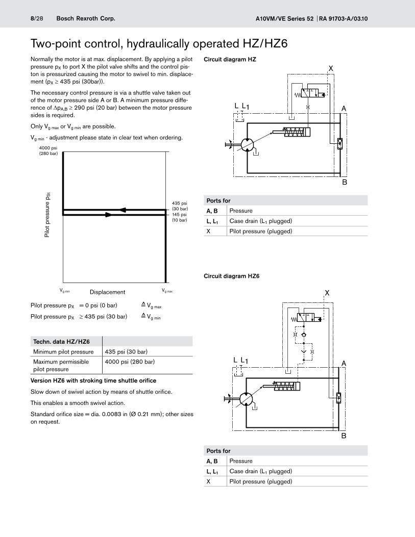
Two-point direct control DGNormally the motor is at max. displacement. By applying an external pressure to port G, the control piston is directly pres-surized and the motor swivels back to min. displacement
The minimum required control pressure is pSt ≥ 580 psi (40 bar)
Please note, that this minimum required control pressure at port G depends directly on the operating pressure pB in port A or B. (Pressure in A or B),see control pressure diagram below. With a control pressure above this minimum required pressure level the motor will destroke properly.
Control pressure diagram
Control pressure = 0 psi (0 bar) = Vg max
Control pressure ≥ 580 psi (40 bar) = Vg min (see diagram)
The max. permissible control pressure is pSt = 4000 psi (280 bar.)
Vgmin adjustment please state in clear text with order
A10VM/VE Series 52 RA 91703-A/03.108/28 Bosch Rexroth Corp.
Circuit diagram HZ
Ports for
A, B Pressure
L, L1 Case drain (L1 plugged)
X Pilot pressure (plugged)
Circuit diagram HZ6
Ports for
A, B Pressure
L, L1 Case drain (L1 plugged)
X Pilot pressure (plugged)
Two-point control, hydraulically operated HZ/HZ6Normally the motor is at max. displacement. By applying a pilot pressure pX to port X the pilot valve shifts and the control pis-ton is pressurized causing the motor to swivel to min. displace-ment (pX ≥ 435 psi (30bar)).
The necessary control pressure is via a shuttle valve taken out of the motor pressure side A or B. A minimum pressure diffe-rence of ∆pA,B ≥ 290 psi (20 bar) between the motor pressure sides is required.
Only Vg max or Vg min are possible.
Vg min - adjustment please state in clear text when ordering.
Pilot pressure pX = 0 psi (0 bar) = Vg max
Pilot pressure pX ≥ 435 psi (30 bar) = Vg min
Techn. data HZ/HZ6
Minimum pilot pressure 435 psi (30 bar)
Maximum permissible pilot pressure
4000 psi (280 bar)
Version HZ6 with stroking time shuttle orifice
Slow down of swivel action by means of shuttle orifice.
This enables a smooth swivel action.
Standard orifice size = dia. 0.0083 in (Ø 0.21 mm); other sizes on request.
AL1L
B
X
AL1L
X
B
4000 psi(280 bar)
Vg min Vg max
435 psi(30 bar)145 psi(10 bar)
^
^
Displacement
Pilo
t pre
ssur
e p S
t
9/28Bosch Rexroth Corp.RA 91703-A/03.10 A10VM/VE Series 52
Circuit diagram EZ1/2
Ports for
A, B Pressure
L, L1 Case drain (L1 plugged)
Connection to solenoid Plug connection to according to DIN 43650 DIN EN 175301-803-A Cable screw joint M 16x1.5
Circuit diagram EZ6/7
Ports for
A, B Pressure
L, L1 Case drain (L1 plugged)
Two-point control, electrically operated EZ1)
Normally the motor is at maximum displacement. By energizing the solenoid of the control valve, the control piston is pressu-rized and the motor swivels to minimum displacement.
The control pressure is via a shuttle valve taken out of the motor pressure side A or B. A minimum pressure difference of ∆pA,B ≥ 290 psi (20 bar) between the pressure sides is required.
The motor can only swivel between Vg max or Vg min.
Vg min - adjustment please state in clear text when ordering.
De-energized = Vg max
Energized = Vg min
Techn. data EZ
Version EZ 1/6 EZ 2/7
Supply voltage 12V DC 24V DC
Nom. current at 68 °F (20°C) 1.5 A 0.8 A
Duty cycler 100% ED 100% ED
Plug protection class to DIN 43650
IP 65 IP 65
Ambient temperature range -4 °F (-20°C) to 140 °F (+60°C). If the above temperature range cannot be met please consult us
Features
– with spring return at solenoid
– Solenoid plug can be turned 4 x 90°
Version EZ6/7 with stroking time shuttle orifice.
Slow down of swivel action by means of shuttle orifice. This enables a smooth swivel action. Standard orifice size = dia 0.0083 in (Ø 0.21mm); other sizes on request.
More information see page 25
12V / 24V
0
V g min V g max
^
^
AL L1
B
AL L1
B
1 2
PEA
1 2
PEA
Shown in the unit dimensions: DIN connector from HIRSCHMANN; 1)
Preferred for mobile applications (other dimensions): DEUTSCH connector molded, 2-pin – without suppressor diode
A10VM/VE Series 52 RA 91703-A/03.1010/28 Bosch Rexroth Corp.
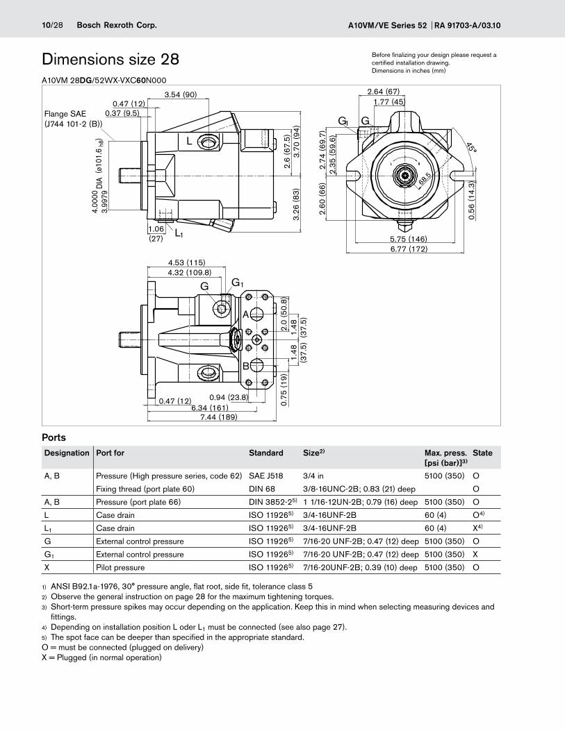
A10VM 28DG/52WX-VXC60N000
Dimensions size 28 Before finalizing your design please request a certified installation drawing. Dimensions in inches (mm)
PortsDesignation Port for Standard Size2) Max. press.
[psi (bar)]3)State
A, B Pressure (High pressure series, code 62) SAE J518 3/4 in 5100 (350) O
Fixing thread (port plate 60) DIN 68 3/8-16UNC-2B; 0.83 (21) deep O
A, B Pressure (port plate 66) DIN 3852-25) 1 1/16-12UN-2B; 0.79 (16) deep 5100 (350) O
L Case drain ISO 119265) 3/4-16UNF-2B 60 (4) O4)
L1 Case drain ISO 119265) 3/4-16UNF-2B 60 (4) X4)
G External control pressure ISO 119265) 7/16-20 UNF-2B; 0.47 (12) deep 5100 (350) O
G1 External control pressure ISO 119265) 7/16-20 UNF-2B; 0.47 (12) deep 5100 (350) X
X Pilot pressure ISO 119265) 7/16-20UNF-2B; 0.39 (10) deep 5100 (350) O
ANSI B92.1a-1976, 30° pressure angle, flat root, side fit, tolerance class 51)
Observe the general instruction on page 28 for the maximum tightening torques.2)
Short-term pressure spikes may occur depending on the application. Keep this in mind when selecting measuring devices and 3)
fittings.Depending on installation position L oder L4) 1 must be connected (see also page 27).The spot face can be deeper than specified in the appropriate standard.5)
O = must be connected (plugged on delivery) X = Plugged (in normal operation)
1.06(27)
L1
L
0.37 (9.5)
3.54 (90)0.47 (12)
3.7
0 (9
4)2.
6 (6
7.5)
3.26
(83)
2.35
(59.
6)2.
74 (6
9.7)
2.60
(66)
G1 G
1.77 (45)2.64 (67)
6.77 (172)5.75 (146)
68.5
45°
0.56
(14.
3)
4.32 (109.8)2.
0 (5
0.8)
1.48
(37.
5)1.
48(3
7.5)
0.75
(19)
0.47 (12)6.34 (161)
7.44 (189)
0.94 (23.8)
A
B
G1
4.53 (115)
G
(ø10
1.6
h8)
4.00
00
3.99
79D
IA
Flange SAE (J744 101-2 (B))
11/28Bosch Rexroth Corp.RA 91703-A/03.10 A10VM/VE Series 52
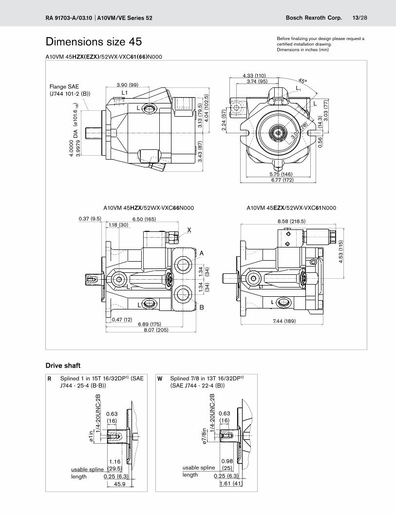
A10VM 28HZX(EZX)/52WX-VXC66N000
Dimensions size 28 Before finalizing your design please request a certified installation drawing. Dimensions in inches (mm)
Drive shaft
R Splined 7/8 in 13T 16/32DP1) (SAE J744 - 22-4 (B))
A10VM/VE Series 52 RA 91703-A/03.1012/28 Bosch Rexroth Corp.
Before finalizing your design please request a certified installation drawing. Dimensions in inches (mm)
A10VM 45DG/52WX-VXC60(61)N000
Dimensions size 45
PortsDesignation Port for Standard Size2) Max. press.
[psi (bar)]3)State
A, B Pressure (high pressure series, code 62) SAE J518 3/4 in 5100 (350) O
Fixing thread (port plate 60) DIN 68 3/8-16UNC-2B; 0.83 (21) deep O
A, B Pressure (port plate 66) DIN 3852-25) 1 1/16-12UN-2B; 0.79 (16) deep 5100 (350) O
L Case drain ISO 119265) 7/8-14UNF-2B 60 (4) O4)
L1 Case drain ISO 119265) 7/8-14UNF-2B 60 (4) X4)
G External control pressure ISO 119265) 7/16-20 UNF-2B; 0.47 (12) deep 5100 (350) O
G1 External control pressure ISO 119265) 7/16-20 UNF-2B; 0.47 (12) deep 5100 (350) X
X Pilot pressure ISO 119265) 7/16-20UNF-2B; 0.39 (10) deep 5100 (350) O
ANSI B92.1a-1976, 30° pressure angle, flat root, side fit, tolerance class 51)
Observe the general instruction on page 28 for the maximum tightening torques.2)
Short-term pressure spikes may occur depending on the application. Keep this in mind when selecting measuring devices and 3)
fittings.Depending on installation position L oder L4) 1 must be connected (see also page 27).The spot face can be deeper than specified in the appropriate standard.5)
O = must be connected (plugged on delivery) X = Plugged (in normal operation)
G1
G
Z
2.60
(66)
3.07
(78)
1.93 (49)2.87 (73)
45°
3.03
(77)
3.07 (78)
0.56
(14.
3)
5.75 (146)6.77 (172)
L
L1
L
L1
3.90 (99)
3.43
(87)
3.07
(78)
3.99
794.
0000
DIA
(ø10
1.6
h8)
0.37 (9.5)
L1
L
6.89 (175)4.35 (110.5)
1.18 (30)
0.47 (12)
4.04
(102
.5)
0.94(23.8)
2.00
(50.
8)1.
48(3
7.5)
1.48
(37.
5)
B
A
1.50(38)
1.50(38)
2.00
(50.
8)
2.00
(50.
8)
30°30°
0.94(23.8)
0.94(23.8)
B A
Flange SAE (J744 101-2 (B))
View Z Port plate 61
Port plate 60
13/28Bosch Rexroth Corp.RA 91703-A/03.10 A10VM/VE Series 52
Before finalizing your design please request a certified installation drawing. Dimensions in inches (mm)
A10VM 45HZX(EZX)/52WX-VXC61(66)N000
Dimensions size 45
Drive shaft
R Splined 1 in 15T 16/32DP1) (SAE J744 - 25-4 (B-B))
W Splined 7/8 in 13T 16/32DP1) (SAE J744 - 22-4 (B))
A10VM/VE Series 52 RA 91703-A/03.1014/28 Bosch Rexroth Corp.
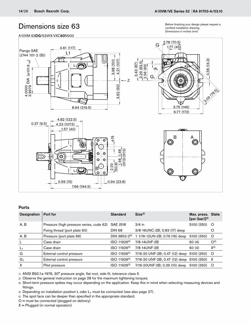
A10VM 63DG/52WX-VXC60N000
Dimensions size 63
PortsDesignation Port for Standard Size2) Max. press.
[psi (bar)]3)State
A, B Pressure (high pressure series, code 62) SAE J518 3/4 in 5100 (350) O
Fixing thread (port plate 60) DIN 68 3/8-16UNC-2B; 0.83 (17) deep O
A, B Pressure (port plate 66) DIN 3852-25) 1 1/16-12UN-2B; 0.79 (16) deep 5100 (350) O
L Case drain ISO 119265) 7/8-14UNF-2B 60 (4) O4)
L1 Case drain ISO 119265) 7/8-14UNF-2B 60 (4) X4)
G External control pressure ISO 119265) 7/16-20 UNF-2B; 0.47 (12) deep 5100 (350) O
G1 External control pressure ISO 119265) 7/16-20 UNF-2B; 0.47 (12) deep 5100 (350) X
X Pilot pressure ISO 119265) 7/16-20UNF-2B; 0.39 (10) deep 5100 (350) O
ANSI B92.1a-1976, 30° pressure angle, flat root, side fit, tolerance class 51)
Observe the general instruction on page 28 for the maximum tightening torques.2)
Short-term pressure spikes may occur depending on the application. Keep this in mind when selecting measuring devices and 3)
fittings.Depending on installation position L oder L4) 1 must be connected (see also page 27).The spot face can be deeper than specified in the appropriate standard.5)
O = must be connected (plugged on delivery) X = Plugged (in normal operation)
AB
#09
1564
93FD
6000
DUES
E N02
.105
--M
6-1.0 001 10
L1
G
G1
A
B
4.82 (122.5)
2.78 (70.5)1.77 (45)
8°
2.56
(65)
3.43
(87)
3.29
(83.
5)
3.62
(92)
0.59 (15)
0.56
(14.
3)
4.61 (117)
Z
5.75 (146)6.77 (172)
3.09 (78.5)
45°
8.64 (219.5)
4.21
(107
)3.
98 (1
01)
(ø10
1.6
h8)
3.99
79D
IA4.
0000
ø19
2.00
(50.
8)
1.48
(37.
5)1.
48(3
7.5)
0.37 (9.5)
1.57 (40)4.23 (107.5)
7.66 (194.5)0.94 (23.8)
Flange SAE (J744 101-2 (B))
Before finalizing your design please request a certified installation drawing. Dimensions in inches (mm)
15/28Bosch Rexroth Corp.RA 91703-A/03.10 A10VM/VE Series 52
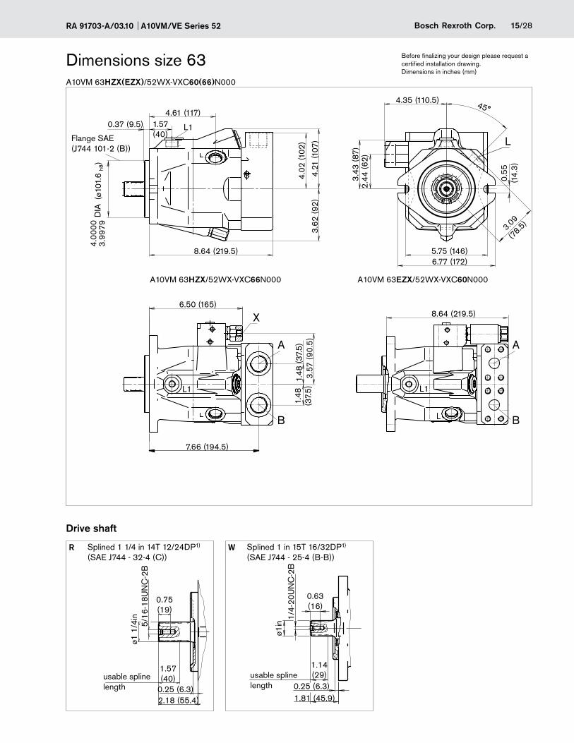
A10VM 63HZX(EZX)/52WX-VXC60(66)N000
Dimensions size 63
Drive shaft
R Splined 1 1/4 in 14T 12/24DP1) (SAE J744 - 32-4 (C))
W Splined 1 in 15T 16/32DP1) (SAE J744 - 25-4 (B-B))
Before finalizing your design please request a certified installation drawing. Dimensions in inches (mm)
A10VM/VE Series 52 RA 91703-A/03.1016/28 Bosch Rexroth Corp.
A10VM 85DG/52WX-VXC60N000
Dimensions size 85
PortsDesignation Port for Standard Size2) Max. press.
[psi (bar)]3)State
A, B Pressure (high pressure series, code 62) SAE J518C 1 in 5100 (350) O
Fixing thread (port plate 60) DIN 68 7/16-14UNC-2B; 0.87 (22) deep O
L Case drain ISO 119265) 1 1/16-12UN-2B 60 (4) O4)
L1 Case drain ISO 119265) 1 1/16-12UN-2B 60 (4) X4)
G external control pressure ISO 119265) 7/16-20 UNF-2B; 0.47 (12) deep 5100 (350) O
G1 external control pressure ISO 119265) 7/16-20 UNF-2B; 0.47 (12) deep 5100 (350) X
ANSI B92.1a-1976, 30° pressure angle, flat root, side fit, tolerance class 51)
Observe the general instruction on page 28 for the maximum tightening torques.2)
Short-term pressure spikes may occur depending on the application. Keep this in mind when selecting measuring devices and 3)
fittings.Depending on installation position L oder L4) 1 must be connected (see also page 27).The spot face can be deeper than specified in the appropriate standard.5)
O = must be connected (plugged on delivery) X = Plugged (in normal operation)
3.43
(87)
4.02
(102
)
0.69
(17.
5)
8.27 (210)7.13 (181)
4.43
(112
.4)
3.54
(90
)
5.04
(128
)
0.98
(ø25
)2.
25(5
7.2)
1.77
(45)
1.77
(45)
1.09 (27.8)
(ø12
7 h8)
4.99
755.
0000
DIA
0.50 (12.7)
0.79 (20)8.80 (223.5)
1.57(40)
10.10 (256.5)5.12 (130)
6.44 (163.5)6.25 (158.7)
2.17 (55)3.07 (78)
45°
3.74 (9
5)
3.68
(93.
5)
G L1L
A
B
G1
L1
L1
Flange SAE (J744 127-2 (C))
Before finalizing your design please request a certified installation drawing. Dimensions in inches (mm)
17/28Bosch Rexroth Corp.RA 91703-A/03.10 A10VM/VE Series 52
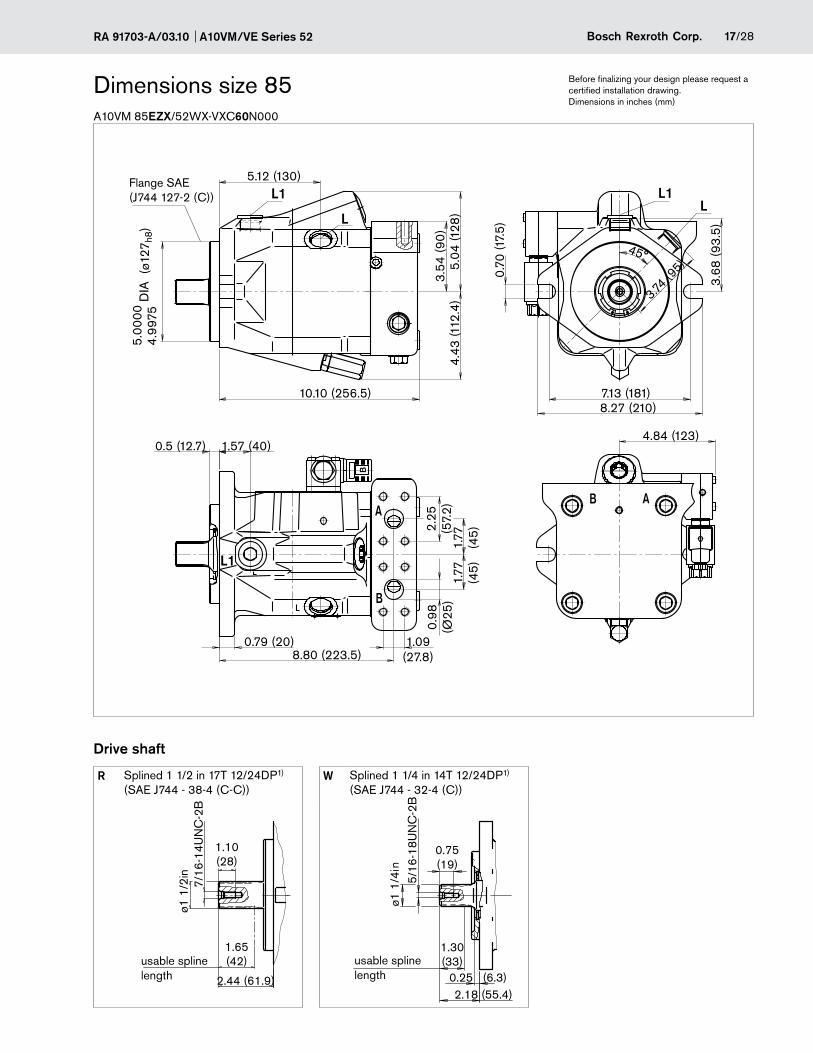
A10VM 85EZX/52WX-VXC60N000
Dimensions size 85
Drive shaft
R Splined 1 1/2 in 17T 12/24DP1) (SAE J744 - 38-4 (C-C))
W Splined 1 1/4 in 14T 12/24DP1) (SAE J744 - 32-4 (C))
Before finalizing your design please request a certified installation drawing. Dimensions in inches (mm)
0.70
(17.
5)
8.27 (210)7.13 (181)
4.43
(112
.4)
3.54
(90
)5.
04 (1
28)
0.98
(Ø25
)2.
25(5
7.2)
1.77
(45)
1.77
(45)
1.09(27.8)
4.84 (123)0.5 (12.7)
0.79 (20)8.80 (223.5)
1.57 (40)
10.10 (256.5)
5.12 (130)
45°
3.74 (9
5)
3.68
(93.
5)
(ø12
7 h8)
4.99
755.
0000
DIA
B
AA
B
B
L1 L1L
L1
L
2.44 (61.9)
1.65(42)
1.10(28)
ø1 1
/2in
7/16
-14U
NC
-2B
ø1 1
/4in
5/16
-18U
NC
-2B
1.30(33)
0.25 (6.3)
0.75(19)
2.18 (55.4)
Flange SAE (J744 127-2 (C))
usable spline length
usable spline length
A10VM/VE Series 52 RA 91703-A/03.1018/28 Bosch Rexroth Corp.
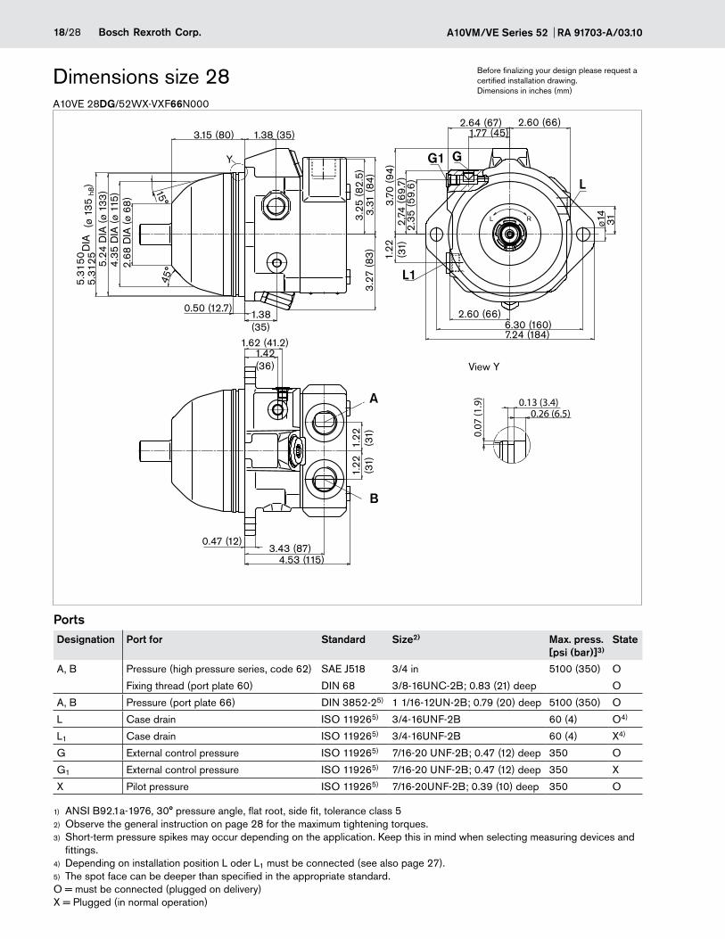
A10VE 28DG/52WX-VXF66N000
Dimensions size 28
PortsDesignation Port for Standard Size2) Max. press.
[psi (bar)]3)State
A, B Pressure (high pressure series, code 62) SAE J518 3/4 in 5100 (350) O
Fixing thread (port plate 60) DIN 68 3/8-16UNC-2B; 0.83 (21) deep O
A, B Pressure (port plate 66) DIN 3852-25) 1 1/16-12UN-2B; 0.79 (20) deep 5100 (350) O
L Case drain ISO 119265) 3/4-16UNF-2B 60 (4) O4)
L1 Case drain ISO 119265) 3/4-16UNF-2B 60 (4) X4)
G External control pressure ISO 119265) 7/16-20 UNF-2B; 0.47 (12) deep 350 O
G1 External control pressure ISO 119265) 7/16-20 UNF-2B; 0.47 (12) deep 350 X
X Pilot pressure ISO 119265) 7/16-20UNF-2B; 0.39 (10) deep 350 O
ANSI B92.1a-1976, 30° pressure angle, flat root, side fit, tolerance class 51)
Observe the general instruction on page 28 for the maximum tightening torques.2)
Short-term pressure spikes may occur depending on the application. Keep this in mind when selecting measuring devices and 3)
fittings.Depending on installation position L oder L4) 1 must be connected (see also page 27).The spot face can be deeper than specified in the appropriate standard.5)
O = must be connected (plugged on delivery) X = Plugged (in normal operation)
Before finalizing your design please request a certified installation drawing. Dimensions in inches (mm)
4.53 (115)
1.42(36)
3.43 (87)
1.22 (31)
1.22 (31)
2.35
(59.
6)
2,74
(69
.7)
2.64 (67)1.77 (45)
15°
0.26 (6.5)0.13 (3.4)
0.07
(1.9
)
0.50 (12.7)
(ø 1
35 h
8)5.
3125
5.31
50D
IA
3.27
(83
)
45°5.
24 D
IA (ø
133
)
2.68
DIA
(ø 6
8)
4.35
DIA
(ø 1
15)
1.38(35)
1.38 (35)3.15 (80)
Y
31
2.60 (66)6.30 (160)7.24 (184)
ø143.
31 (8
4)3.
25 (8
2.5)
1.62 (41.2)
1.22 (31)
3.70
(94)
2.60 (66)
0.47 (12)
G
A
B
L
G1
L1
L R
View Y
19/28Bosch Rexroth Corp.RA 91703-A/03.10 A10VM/VE Series 52
A10VE 28HZX(EZX)/52WX-VXF60N000
Dimensions size 28
Drive shaft
R Splined 7/8 in 13T 16/32DP1) (SAE J744 - 22-4 (B))
Before finalizing your design please request a certified installation drawing. Dimensions in inches (mm)
A10VM/VE Series 52 RA 91703-A/03.1020/28 Bosch Rexroth Corp.
Before finalizing your design please request a certified installation drawing. Dimensions in inches (mm)
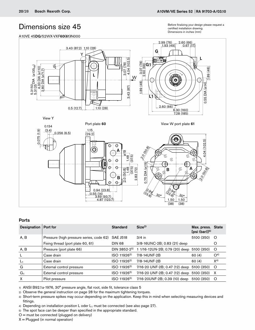
A10VE 45DG/52WX-VXF60(61)N000
Dimensions size 45
PortsDesignation Port for Standard Size2) Max. press.
[psi (bar)]3)State
A, B Pressure (high pressure series, code 62) SAE J518 3/4 in 5100 (350) O
Fixing thread (port plate 60, 61) DIN 68 3/8-16UNC-2B; 0.83 (21) deep O
A, B Pressure (port plate 66) DIN 3852-25) 1 1/16-12UN-2B; 0.79 (20) deep 5100 (350) O
L Case drain ISO 119265) 7/8-14UNF-2B 60 (4) O4)
L1 Case drain ISO 119265) 7/8-14UNF-2B 60 (4) X4)
G External control pressure ISO 119265) 7/16-20 UNF-2B; 0.47 (12) deep 5100 (350) O
G1 External control pressure ISO 119265) 7/16-20 UNF-2B; 0.47 (12) deep 5100 (350) X
X Pilot pressure ISO 119265) 7/16-20UNF-2B; 0.39 (10) deep 5100 (350) O
ANSI B92.1a-1976, 30° pressure angle, flat root, side fit, tolerance class 51)
Observe the general instruction on page 28 for the maximum tightening torques.2)
Short-term pressure spikes may occur depending on the application. Keep this in mind when selecting measuring devices and 3)
fittings.Depending on installation position L oder L4) 1 must be connected (see also page 27).The spot face can be deeper than specified in the appropriate standard.5)
O = must be connected (plugged on delivery) X = Plugged (in normal operation)
4.04
(102
.5)
1.89
(48
)2.
60 (6
6)
3.07
(78
)
0.55 (14)
0.134(3.4)
0.07
5 (1
.9)
0.256 (6.5)
1.48
(37.
5)1.
48(3
7.5)
2.0
(50.
8)
0.94 (23.8)
4.87 (123.7)
3.07
(78
)
7.28 (185)
2.80
DIA
(ø71
.7)
3.69 (93.7)
3.43 (87.2) 1.10 (28)
W
40°
1.89
(48
)
2.83
(72)
2.60 (66)0.67 (17)1.93 (49)
2.99 (76)
0.55
DIA
(ø14
)
2.60 (66)6.30 (160)
4.33
DIA
(ø11
0)
(ø13
5 h8)
5.31
25D
IA5.
3150
ø19
1.10 (28)0.5 (12.7)
19°
1.15(29.2)
3.43
(87)
Y
B
B
A
A
G
LG1
L R
L1
L
4.04
(102
.5)
2.0
(50.
8)
2.0
(50.
8)0.
75 D
IA (ø
19)
1.50(38)
1.50(38)
30°
0.94(23.8)
0.94(23.8) 30°
View W port plate 61Port plate 60View Y
21/28Bosch Rexroth Corp.RA 91703-A/03.10 A10VM/VE Series 52
Before finalizing your design please request a certified installation drawing. Dimensions in inches (mm)
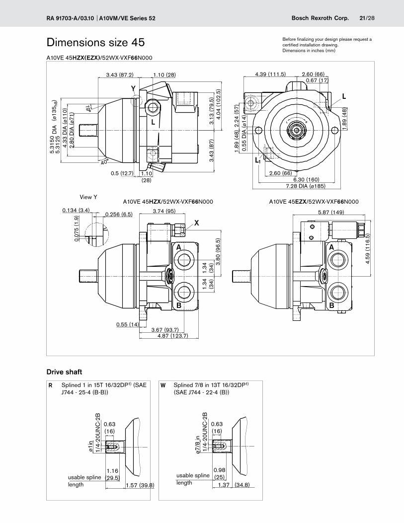
A10VE 45HZX(EZX)/52WX-VXF66N000
Dimensions size 45
Drive shaft
R Splined 1 in 15T 16/32DP1) (SAE J744 - 25-4 (B-B))
W Splined 7/8 in 13T 16/32DP1) (SAE J744 - 22-4 (B))
A10VM/VE Series 52 RA 91703-A/03.1022/28 Bosch Rexroth Corp.
Before finalizing your design please request a certified installation drawing. Dimensions in inches (mm)
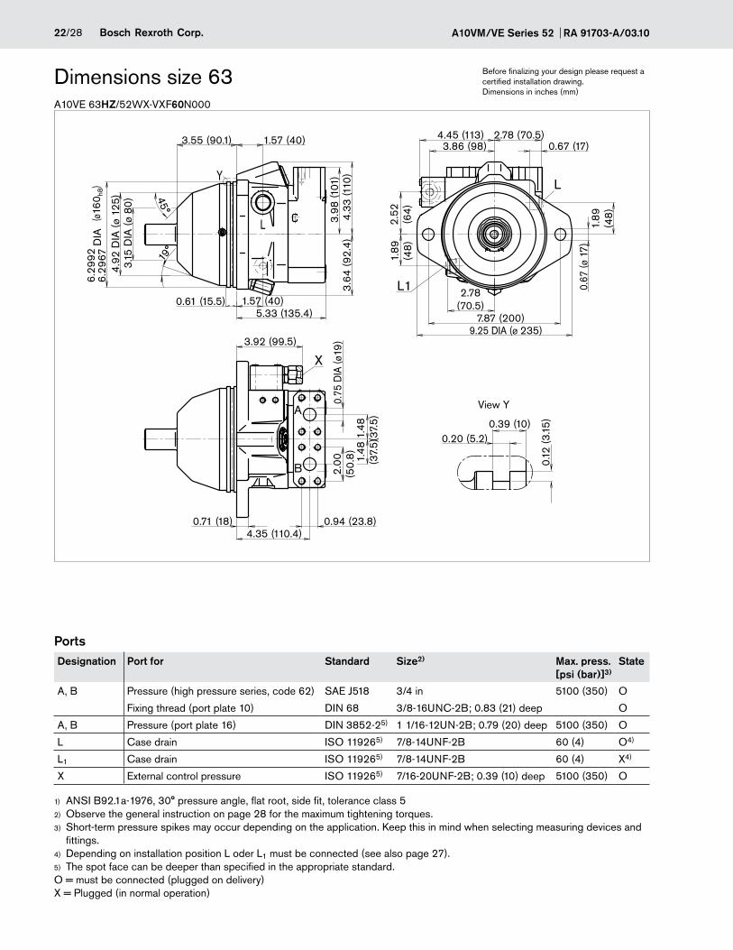
A10VE 63HZ/52WX-VXF60N000
Dimensions size 63
PortsDesignation Port for Standard Size2) Max. press.
[psi (bar)]3)State
A, B Pressure (high pressure series, code 62) SAE J518 3/4 in 5100 (350) O
Fixing thread (port plate 10) DIN 68 3/8-16UNC-2B; 0.83 (21) deep O
A, B Pressure (port plate 16) DIN 3852-25) 1 1/16-12UN-2B; 0.79 (20) deep 5100 (350) O
L Case drain ISO 119265) 7/8-14UNF-2B 60 (4) O4)
L1 Case drain ISO 119265) 7/8-14UNF-2B 60 (4) X4)
X External control pressure ISO 119265) 7/16-20UNF-2B; 0.39 (10) deep 5100 (350) O
ANSI B92.1a-1976, 30° pressure angle, flat root, side fit, tolerance class 51)
Observe the general instruction on page 28 for the maximum tightening torques.2)
Short-term pressure spikes may occur depending on the application. Keep this in mind when selecting measuring devices and 3)
fittings.Depending on installation position L oder L4) 1 must be connected (see also page 27).The spot face can be deeper than specified in the appropriate standard.5)
O = must be connected (plugged on delivery) X = Plugged (in normal operation)
X
A
B 0.12
(3.15
)
L1
L
L
Y
5.33 (135.4)
4.33
(110
)3.
98 (1
01)
2.52
(64)
3.86 (98)4.45 (113)
3.92 (99.5)
1.89
(48
)
2.78 (70.5)0.67 (17)
(ø16
0 h8)
6.29
676.
2992
DIA
4.92
DIA
(ø 1
25)
3.64
(92.
4)
1.57 (40)
0.75
DIA
(ø19
)2.
00(5
0.8
)
0.94 (23.8)
0.20 (5.2)0.39 (10)
4.35 (110.4)0.71 (18)
19°
45°
3.15
DIA
(ø 8
0)
1.48
(37.
5)1.
48(3
7.5)
2.78(70.5)
7.87 (200)9.25 DIA (ø 235)
0.67
(ø 1
7)
1.89
(48
)
3.55 (90.1) 1.57 (40)
0.61 (15.5)
View Y
23/28Bosch Rexroth Corp.RA 91703-A/03.10 A10VM/VE Series 52
Before finalizing your design please request a certified installation drawing. Dimensions in inches (mm)
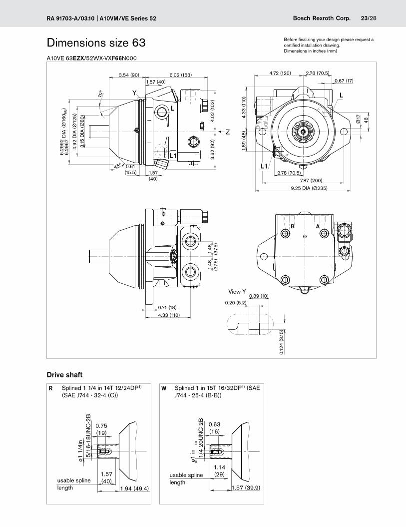
A10VE 63EZX/52WX-VXF66N000
Dimensions size 63
Drive shaft
R Splined 1 1/4 in 14T 12/24DP1) (SAE J744 - 32-4 (C))
W Splined 1 in 15T 16/32DP1) (SAE J744 - 25-4 (B-B))
4.02
(102
)
0.20 (5.2)0.39 (10)
48
4.33
(110
)1.
89 (4
8)
2.78 (70.5)
7.87 (200)
9.25 DIA (Ø235)
1.57(40)
0.61(15.5)
45°
19°
(Ø16
0 h8)
6.29
676.
2992
DIA
3.15
DIA
(Ø80
)
4.92
DIA
(Ø12
5)6.02 (153)3.54 (90)
1.57 (40)
3.62
(92)
0.67 (17)
2.78 (70.5)4.72 (120)
Ø17
1.48
(37.
5)1.
48(3
7.5)
0.71 (18)
4.33 (110)
0.12
4 (3
.15)
Y
Z
B A
L
L1
L
L1
0.75(19)
5/16
-18U
NC
-2B
ø1 1
/4in
1.57(40)
1.94 (49.4)
0.63(16)
1/4-
20U
NC
-2B
ø1 in
1.14(29)
1.57 (39.9)
View Y
usable spline length
usable spline length
A10VM/VE Series 52 RA 91703-A/03.1024/28 Bosch Rexroth Corp.
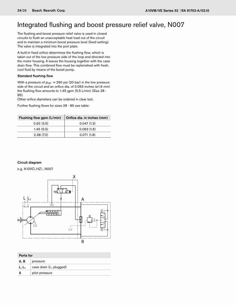
Integrated flushing and boost pressure relief valve, N007The flushing and boost pressure relief valve is used in closed circuits to flush an unacceptable heat load out of the circuit and to maintain a minimum boost pressure level (fixed setting). The valve is integrated into the port plate.
A built-in fixed orifice determines the flushing flow, which is taken out of the low pressure side of the loop and directed into the motor housing. It leaves the housing together with the case drain flow. This combined flow must be replenished with fresh, cool fluid by means of the boost pump.
Standard flushing flow
With a pressure of pND = 290 psi (20 bar) in the low pressure side of the circuit and an orifice dia. of 0.063 inches (ø1.6 mm) the flushing flow amounts to 1.45 gpm (5.5 L/min) (Size 28 - 85). Other orifice diameters can be ordered in clear text.
Further flushing flows for sizes 28 - 85 see table:
Flushing flow gpm (L/min) Orifice dia. in inches (mm)
0.92 (3.5) 0.047 (1.2)
1.45 (5.5) 0.063 (1.6)
2.38 (7.2) 0.071 (1.8)
Circuit diagram
e.g. A10VO..HZ/...N007
Ports for
A, B pressure
L, L1 case drain (L1 plugged)
X pilot pressure
AL L1
B
X
25/28Bosch Rexroth Corp.RA 91703-A/03.10 A10VM/VE Series 52
DEUTSCH WKM08130D-01-C-V-XXDN, 2-pin
Molded, without bidirectional suppressor diode (Standard) __________________________________________P
A10VM/VE Series 52 RA 91703-A/03.1026/28 Bosch Rexroth Corp.
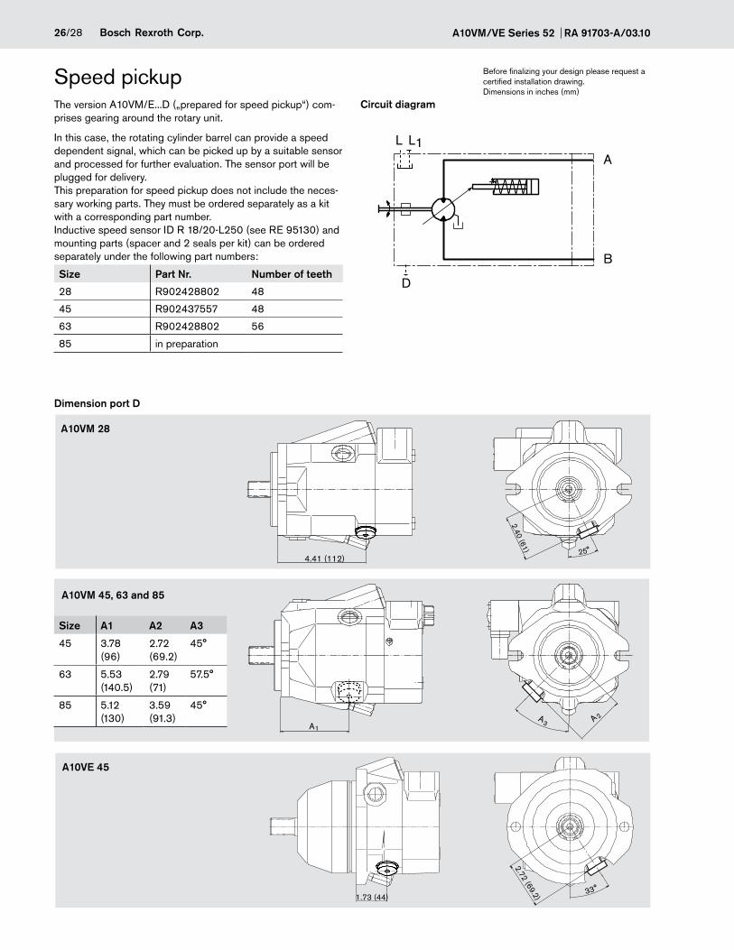
The version A10VM/E...D („prepared for speed pickup“) com-prises gearing around the rotary unit.
In this case, the rotating cylinder barrel can provide a speed dependent signal, which can be picked up by a suitable sensor and processed for further evaluation. The sensor port will be plugged for delivery. This preparation for speed pickup does not include the neces-sary working parts. They must be ordered separately as a kit with a corresponding part number. Inductive speed sensor ID R 18/20-L250 (see RE 95130) and mounting parts (spacer and 2 seals per kit) can be ordered separately under the following part numbers:
Size Part Nr. Number of teeth
28 R902428802 48
45 R902437557 48
63 R902428802 56
85 in preparation
Dimension port D
Speed pickup
A10VE 45
A10VM 28
Size A1 A2 A3
45 3.78 (96)
2.72 (69.2)
45°
63 5.53 (140.5)
2.79 (71)
57.5°
85 5.12 (130)
3.59 (91.3)
45°
A10VM 45, 63 and 85
Circuit diagram
Before finalizing your design please request a certified installation drawing. Dimensions in inches (mm)
25°
2.40 (61)
4.41 (112)
1.73 (44)33°
2.72 (69.2)
A1A
3 A 2
AL1L
B
D
27/28Bosch Rexroth Corp.RA 91703-A/03.10 A10VM/VE Series 52
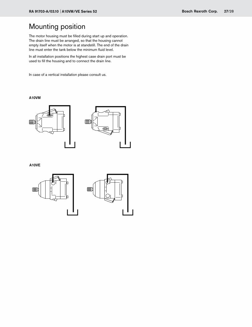
Mounting positionThe motor housing must be filled during start up and operation. The drain line must be arranged, so that the housing cannot empty itself when the motor is at standstill. The end of the drain line must enter the tank below the minimum fluid level.
In all installation positions the highest case drain port must be used to fill the housing and to connect the drain line.
In case of a vertical installation please consult us.
A10VM
A10VE
A10VM/VE Series 52 RA 91703-A/03.1028/28 Bosch Rexroth Corp.
All rights reserved. Neither this document, nor any part of it, may be reproduced, duplicated, circulated or disseminated, whether by copy, electronic format or any other means, without the prior consent and authorization of Bosch Rexroth Corp.
The data and illustrations in this brochure/data sheet are intended only to descri-be or depict the products. No representation or warranty, either express or im-plied, relating to merchantability or fitness for intended use, is given or intended by virtue of the information contained in this brochure/data sheet. The information contained in this brochure/data sheet in no way relieves the user of its obligation to insure the proper use of the products for a specific use or application. All products contained in this brochure/data sheet are subject to normal wear and tear from usage.
General instructionsThe A10VM/VE is designed for operation in open and closed circuits
Systems design, installation and commissioning requires trained technicians or tradesmen.
Be sure to read the entire operating instructions throughly and completely befor using the axial piston unit. If necessary, request them at Rexroth.
All hydraulic ports can only be used for the fastening of hydraulic service lines.
During and shortly after operation of a axial piston unit the housing and especially a solenoid can be extremely hot, avoid being burned; take suitable safety measures (wear protective clothing).
Dependent on the operating conditions of the axial piston unit (operating pressure, fluid temperature) deviations in the perfor-mance curves can occur.
Pressure ports: All materials and port threads are selected and designed in such a manner, that they can withstand the maximum pressure. The machine and system manufacturer must ensure, that all connecting elements and hydraulic lines are suitable for the actual operating pressures.
Pressure cut off and pressure control are not suitable for providing system protection against excessive pressures. A suitable overall main line relief valve must be incorporated.
All given data and information must be adhered to.
The following tightening torques are valid:
- Female threads in the axial piston unit: the maximum permissible tightening torques MG Max are maximum values for the female threads in the pump casting and may not be exceeded. Value see table below.
- Fittings: please comply with the manufacturer‘s information regarding the max. permissible tightening torques for the used fittings.
- Fastening bolts: for fastening bolts to ISO 68 we recommend to check the permissible tightening torques in each individual case to VDI 2230.
- Plugs: for the metal plugs, supplied with the axial piston unit the following min. required tightening torques MV apply (see table).
Threaded port sizesMaximum permissible tightening torque of the threaded holes MG max
Requiered tightening torque of the locking screws MV