AXION micro5 Instruction Manual Read This First THIS INSTRUCTION MANUAL IS THE MOST IMPORTANT ACCESSORY OF THE MICRO5. IT SHOULD BE READ AT LEAST TWICE BEFORE OPERATION OF THE INSTRUMENT. THE MICRO5 IS A VERY ADVANCED ELECTRONIC DEVICE. THE MICRO-PROCESSOR CONTROLS ARE DESIGNED TO SIMPLIFY TREATMENT DELIVERY. WE HAVE MADE THE OPERATION OF THE micro5 VERY SIMPLE IF YOU FOLLOW THE BASIC GUIDE- LINES OF THE INSTRUCTION MANUAL. REMEMBER, MOST PROBLEMS ARE A RESULT OF FAILURE TO FOLLOW DIRECTIONS RATHER THAT EQUIPMENT FAILURE. THE MICRO5 IS SHIPPED WITH A LOW BATTERY CHARGE. IT MUST BE CHARGED AT LEAST 15 HOURS BEFORE FIRST USE. IF YOU HAVE DETERMINED THAT A SYSTEMS FAILURE EXISTS, CALL FOR INSTRUC- TIONS.
Transcript
AXION micro5 Instruction Manual
Read This First
THIS INSTRUCTION MANUAL IS THE MOST IMPORTANT ACCESSORY OF THE MICRO5. IT SHOULD BE READ AT LEAST TWICE BEFORE OPERATION OF THE INSTRUMENT.
THE MICRO5 IS A VERY ADVANCED ELECTRONIC DEVICE. THE MICRO-PROCESSOR CONTROLS ARE DESIGNED TO SIMPLIFY TREATMENT DELIVERY. WE HAVE MADE THE OPERATION OF THE micro5 VERY SIMPLE IF YOU FOLLOW THE BASIC GUIDE-LINES OF THE INSTRUCTION MANUAL. REMEMBER, MOST PROBLEMS ARE A RESULT OF FAILURE TO FOLLOW DIRECTIONS RATHER THAT EQUIPMENT FAILURE.
THE MICRO5 IS SHIPPED WITH A LOW BATTERY CHARGE. IT MUST BE CHARGED AT LEAST 15 HOURS BEFORE FIRST USE.
IF YOU HAVE DETERMINED THAT A SYSTEMS FAILURE EXISTS, CALL FOR INSTRUC-TIONS.
Power UpThe micro5 is turned ON/OFF by a momentary switch located on the back of the instrument, in the lower Right hand corner. The switch will activate the unit with a slight touch and the entire LCD display will light up. The micros has a built in battery saver that will automatically turn the unit off within five minutes of idle time. When the micros is turned on again it will display the last treatment settings used.
When the instrument is first turned on, it will run an internal self-diagnostic test lasting about three sec-onds. During this test all the LCD segments will display. A successful test will be followed by a series of alternating high and low tones indicating the instrument is ready for operation. A failure of the test is followed by a series of tones along with a flashing TEST indicator on the LCD screen. If the micros should fail a power-up test, contact us for instructions. To facilitate return shipping in the event of a failure, we recommend keeping the original shipping container.
IntroductionMicrocurrent instruments use very small amounts of current (micro-amperage) to treat many of the same conditions normally associated with high output (milliamperes) instruments. Microcurrent stimulation is usually sub-sensory and often imperceptible to the patient. The current is able to pass through the skin with-out much stimulation to motor or sensory nerves. Therefore, microcurrent stimulation is comfortable to the patient and enhances patient compliance.
The AXION micro5 low volt, pulsed micro-amp stimulator utilizes micro-processor controls and touch pad operation. The ease of operation allows the clinician to quickly, accurately and efficiently administer the desired treatments to the patient. In addition, by using pre-programmed presets, the micro5 reduces confu-sion of treatment selections often associated with microcurrent stimulators. A full manual over-ride is also offered for the clinician who wants to customize a treatment for a patient.
For the clinician, novice or experienced in microcurrent stimulation, the micro5 provides an easy to operate, yet highly sophisticated therapy system. The outstanding clinical results you will achieve with microcurrent stimulation will convince you of its place in a comprehensive pain management program.
The AXION micro5 is the most advanced microcurrent stimulator available. Each time the micro5 is turned on it performs the following self-diagnostic tests.
RAM, ROM, CPU, Display, Output tests
During operation the micro5 uses distinct and different tones as well as display indicators to alert the opera-tor of systems problems.
123
45
Front Panel Operation1. “A”. Pressing this red key sets the parameters of the selected channels for the “A” default.
2. “C”. Pressing this blue key sets the parameters of the channels selected for the “C” default.
3. “E”. Pressing this green key sets the parameters of the selected channels for the “E” default.
4. “M”. Pressing this yellow key sets the parameters of the selected channels for the “M” default.
5. “I”. Pressing this white key sets the parameters for the channels selected for the “I” default.
6. CH 1. Press this key to program channel one.
7. CH 2. Press this key to program channel two.
8. COMB. Press this key to program both channels at once.
678
9
9. NEXT. Pressing this key when programming the waveslope or polarity will toggle between the various options available. This key also allows access to m5 special features
10. PROBE. Pressing this key turns on the probe operation and the three segment LCD probe display.
11. LOCK. This key locks the Search display readings on the screen.
12. START. Pressing this key starts the countdown operation of the instrument. It will also silence the beep that is heard every ten seconds during operation.
13. STOP. Pressing this key suspends treatment.
14. KEY PAD NUMBERS 0-9. These keys allow manual programming of the various parameters and access to special features.
15. CLR/ENT. Pressing these keys will either clear and entry made or enter the selection and ad vance to the next parameter to program.
10
11
121314
15
Pad lead wires
Active Probe
Indifferent Probe
micro5 FeaturesPre-programmed Treatment ModesThe AXION micro5 is the first microcurrent instrument to offer six pre-programmed treatment modes. This feature allows the clinician to set the output, frequency, waveslope, polarity and treatment times at the touch of a single keypad. These treatment modes represent the most effective applications available for microcur-rent stimulation.
The following table illustrates the parameter setting for each of the modes. These values will appear on the LCD screen when the mode is selected.
A C E M I ProbeuA 400 200 40 100 400 200Hz .6 .3 .6 200 100Wave gentle standard standard standard standard standardPolarity bi bi bi bi bi biTime 15 min 15 min 15 min 15 min 15 min 10 sec
Just press the preset button and then Start.
Full manual over-ride is also available for fully customized treatments.
Using PresetsThe preset treatment regimens of the micro5 have been determined after years of clinical use. They represent the most effective parameters for those indications. However you can manually over-ride and vary any of the parameters especially if you have preferred settings or are not getting the desired results.
With microcurrent stimulation it is important to determine the type of pain being treated. Upon evaluation, try to identify the pain as acute or chronic.
Electrical stimulation is still part science part art. There have not been definitive settings established for vari-ous conditions. However some general guidelines can be used with confidence.
1.”A”.The “A” preset can be used for acute pain patients. The settings are designed to bring about the most rapid pain relief. If you feel the condition is an acute exacerbation of an existing condition then treat with “A” for 15 minutes followed by “C” for 15 minutes. If inflammation is present use “A” for 15 minutes followed by “E” for 15 minutes.
2. “C”. The “C” preset can be used with low grade pain patients. Dull, aching pain would be a typical descrip-tion of the pain usually treated with “C”.
3. “E”.The “E” preset can be used if there is inflammation present. This setting can be used after treatment us-ing another preset.
4. “M”.The “M” preset is user defined. See section on new features.
S.”I”.The “I’ preset is used when a large area is treated. This preset uses both channels to deliver the current through four pads. The micro5 uses both a rate scan and vector scan. When using the “I” preset you will notice the numbers on the display might change rapidly during treatment. This is normal and reflects the operation of the rate and vector scan. To over-ride the “I” preset settings, press “ENT ‘ then enter the parameters you want, then press START. After the instrument has been turned on and successfully passed the diagnostic check, it can be programmed for treatment. Select the channel to be used or press COMB to program both channels at once. (A tone should be heard whenever a panel key is pressed. This confirms a selec tion has been made. If you do not hear a tone, press the button again until a tone is heard.) When a channel has been selected, the MICROAMPS setting will flash for that channel. This confirms that programming can begin. Now simply select the desired preset (A,C,E,M or I).
The settings for that selection will now appear on the LCD display for that channel. If these are the settings you want you may begin treatment by pressing START. After the START key has been pressed you will see the minute or second indicator in the time field begin to flash. This con firms that treatment has begun and the timer is counting down. Every ten seconds during treatment a beep is heard to confirm that the instrument is running. This beep can be turned off by pressing the START key during treatment. After time has elapsed, a series of tones are heard to signal the end of treatment.
To Recap:
1. Select Channel2. Select Preset3. Press START
Adjustable Parameters
The micro5 provides you with complete control over the following parameters; microamps, frequency, waveslope, polarity and time. This allows for maximal flexibility when programming treatment param-eters for each patient
The Parameter Ranges Are As Follows:
Manual OverrideTo enter settings other than the presets proceed as follows:
Micro-ampsSelect the channel(s) to be programmed. When the micro-amp field is flashing you may enter any range from 1-750uA using the numerical key pad. If the micro-amp field is the only field you want to change you do not need to press the ENTER key, you may proceed to the START key. For example if you wanted to enter 600 uA you would press 6,0,0.To enter 60uA you do not need to press 0,6,0. Simply press 6,0. If you make an entry error or change your mind you can press the CLR key to clear the entry and start again. Pressing CLR clears only the parameter being programmed and not the remaining parameters. NOTE: any entry above 750uA will default back to 750uA. After the settings are entered you can move to the next parameter by pressing the ENT key. To pass over a parameter simply keep pressing the ENT key until you have reached the parameter you want to program.
FrequencyWhen entering the frequency settings use the 0 key to enter frequencies less than one. For example to enter .6Hz you would press 0,6. To enter numbers greater than .9 simply enter the number direct. l5OHz would be enter as 1,5,0. If you want to change the waveslope press ENT after the frequency has been entered.
WaveslopeTo change the waveslope the waveslope indicator must be flashing. Pressing the NEXT key will toggle you between the two selections available, Standard or Gentle.
PolarityTo change the polarity the polarity indicator must be flashing. Pressing the NEXT key will toggle you between the three setting available, Positive Only, Negative only, BI (Alternating)
TimeTo change time the current time must be flashing. Seconds are entered by beginning the entry with 0. For exam-ple ten seconds would be entered as 0,1,0. A correct seconds entry will be followed by the time indicator chang-ing from minutes (m) to seconds (s). Minutes are entered by pressing the desired time directly. For example ten minutes is entered by pressing 1,0. To change from seconds to minutes press the CLR key
After all parameters have been entered and you want to make a change, simply press the ENT key until the parameter you want to change is flashing. Now make the change. You do not have to press CLR to make your change.
You may program both channels at once by pressing the COMB (combined) key.
You may press the START key at any time during programming. You do not have to be in the time setting to start. After pressing START, the parameter field will stop flashing and the time indicator (m or s) will begin to flash. This confirms the timer is counting down. Every ten seconds you will hear a beep to confirm that the unit is still counting down. To turn off this tone simply press the START key again. This operation will toggle you between tone on and tone off.
You can interrupt a treatment by pressing the STOP key. Because the micro5 uses independent timers for each channel you must be in the channel you want to stop to actually stop that channel. For example to stop only channel one while both channels are running, press CHI then STOP. If you want to stop both channels you may press COMB then STOP. Pressing the START key after STOP will resume the treatment where you left off.
After the timer has timed out, the micro5 will hold the current settings in memory until any changes are made. The instrument will go into a “sleep” mode five minutes after time has expired.
Delivering CurrentThe micro5 delivers the current either from standard electrodes, or in the Probe Mode using Q-Tips moist-ened with tap water. We supply a sample of reusable self-adhesive electrodes. These types of electrodes are readily available for sale through several places on the Internet, or through us.
When using Q-Tips, please purchase the paper shaft Q-Tip brand. There really is a difference. Never use the plastic shaft (they don’t conduct electricity), and be sure to watch the instruction video on the proper insertion of the Q-Tip.
Reusable electrodes have a life span of about 4-5 uses. The micro5 will alert you through it Secure Alert warning tones if the electrode is failing.
If using reusable electrodes, make sure you prep the skin using alcohol swabs to remove as much skin oils as possible. Oil does not conduct electricity AND it quickly breaks down the adhesive gel of the electrode which is designed to both adhere to the skin and conduct electricity.
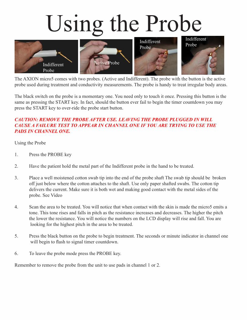
The AXION micro5 comes with two probes. (Active and Indifferent). The probe with the button is the active probe used during treatment and conductivity measurements. The probe is handy to treat irregular body areas.
The black switch on the probe is a momentary one. You need only to touch it once. Pressing this button is the same as pressing the START key. In fact, should the button ever fail to begin the timer countdown you may press the START key to over-ride the probe start button.
CAUTION: REMOVE THE PROBE AFTER USE. LEAVING THE PROBE PLUGGED IN WILL CAUSE A FAILURE TEST TO APPEAR IN CHANNEL ONE IF YOU ARE TRYING TO USE THE PADS IN CHANNEL ONE.
Using the Probe
1. Press the PROBE key
2. Have the patient hold the metal part of the Indifferent probe in the hand to be treated.
3. Place a well moistened cotton swab tip into the end of the probe shaft The swab tip should be broken off just below where the cotton attaches to the shaft. Use only paper shafted swabs. The cotton tip delivers the current. Make sure it is both wet and making good contact with the metal sides of the probe. See Video
4. Scan the area to be treated. You will notice that when contact with the skin is made the micro5 emits a tone. This tone rises and falls in pitch as the resistance increases and decreases. The higher the pitch the lower the resistance. You will notice the numbers on the LCD display will rise and fall. You are looking for the highest pitch in the area to be treated.
5. Press the black button on the probe to begin treatment. The seconds or minute indicator in channel one will begin to flash to signal timer countdown.
6. To leave the probe mode press the PROBE key.
Remember to remove the probe from the unit to use pads in channel 1 or 2.
Using the ProbeIndifferent Probe
Indifferent Probe
Indifferent Probe
Active Probe
A unique feature of the AXION micro5 is PROBE LOCK. Pressing this key while in the probe mode allows the clinician to scan the area for exactly two seconds. After two seconds the highest reading encountered will remain on the LCD display until another point is touched.
Using PROBE LOCK
1. Press the PROBE key.2. Press the LOCK key. The word LOCK should appear in the upper portion of the screen. 3. To disable probe lock press the LOCK key again.
This feature is also very useful in measuring the electrode/skin interface to determine ifgood contact is being made before electrode use.
Probe Lock
During operation the micro5 uses distinct and different tones as well as display in dicators to alert the opera-tor of systems problems. The indicator are as follows.
Upon Start UpAn alternating series of high and low tones indicates a successful initial start up test.
During OperationA series of descending tones along with a flashing battery indicator and flashing testindicator means a low battery charge. You should charge the battery as soon as possible.
A series of descending tones along with a flashing test indicator and flashing channel indicator indicates a current test failure.
The AXION micro5 utilizes a unique monitoring system called INSTANT ALERT. During treatment IN-STANT ALERT works in the background to measure the amount of electricity delivered to the patient Be-cause the micro5 is a computer driven constant current generator it will always strive to maintain the settings you have entered regardless of skin impedance. There are several things that will cause INSTANT ALERT to issue a current test failure.
Note: INSTANT ALERT will indicate which channel is failing by flashing TEST along with the appropriate channel indicator.
MAKE SURE THE MAIN PROBE IS UNPLUGGED BEFORE USING ELECTRODES IN CHANNEL
ONE. 1. Low Battery. If batteries are too low, proper output cannot be maintained. If the battery charge indicator is flashing, charge the batteries as soon as possible. See section on batteries to determine voltage.
2. Defective lead wires. If there is a break in the lead wires INSTANT ALERT will show a current test fail ure. To test for lead wire failure plug a set of lead wires into channel 1. Press the PROBE button to enter into the probe mode. Touch the exposed lead wire metal tips together. The LCD probe display should read over 400. If it does not this means a break somewhere in the lead wire. Shake the lead wire to see if the break causes an intermittent problem. Replace the defective lead wire.
3. Defective electrodes. Carbon Silicone electrodes have a natural useful life of about 6-8 months. Bad electrodes can impede the flow of current and cause INSTANT ALERT to issue a current test failure. Try a new set of electrodes.
Multi-application electrodes have several components that can break down and cause a failure. Even new elec-trodes can be bad. Try another pair.
CAUTION: THERE ARE NO USER SERVICEABLE PARTS OTHER THAN BATTERIES. DO NOT OPEN THE INSTRUMENT WITHOUT INSTRUCTIONS FROM THE COMPANY.
The probe is also connected to the INSTANT ALERT system. Breaking contact with the skin during treatment will cause a current test failure.
Note: INSTANT ALERT current test operates by capturing samples to measure against what is entered on the screen. At lower frequencies it may take the microprocessor a little extra time to find a sample to measure. This will account for the slight lag in showing a failure in the lower frequencies.
The AXION micro5 uses a combination of power sources.
Display MemoryOne button type lithium battery not accessible to the user. When this battery fails the instrument will no longer display the last entry upon start up. The unit must be returned to us to replace this battery.
Main Processor Board and OutputThree high capacity “D” size NiMH batteries. Recharge these batteries using the supplied USB charger, Com-puter USB port or auto USB port. Charging time is about 6 hours for a full charge. When charging make sure the charging indicator light is on. This light is located on the back of the micro5. The low battery indicator will turn on when it is time to recharge. THE UNIT CANNOT BE USED DURING CHARGING.
To keep the channels isolated, channel two has its own rechargeable power source. These batteries are recharged at the same time the main batteries are recharged so no extra steps are needed.
During charging the micro5 will turn it self off. This prevents operation with the charger plugged in. TURN THE MICRO5 OFF BEFORE CHARGING. Should the device ever fail to turn on, make sure that the charging cord is not plugged into the back of the device. If unit still fails to turn on, contact Company.
CPT Billing Codes Suggestions
64550 (TENS)97118 (electrical Stimulation)97200 (physical medicine, combined modalities, 1/2 hr.) 97201 (additional 15 min. added to 97200) 97014 (electrical stimulation)
Contraindications1. Do not stimulate over the Carotid Sinus region.
2. The use of T.E.N.S. on individuals with demand type cardiac pacemakers may be hazardous.
3. Do not stimulate transcerebrally (through the head).
4. Do not use T.E.N.S. whenever pain syndromes are undiagnosed until the etiology is established.
Warnings1. The safety of T.E.N.S. devices for use during pregnancy or delivery has not been established.
2. T.E.N.S. is not effective for pain of central origin.
3. T.E.N.S. devices should be used only under the continued supervision of a licensed practitioner.
4. T.E.N.S. devices have no curative value.
5. T.E.N.S. is a symptomatic treatment and as such suppresses the sensation of pain which would other wise serve as a protective mechanism.
6. The user must keep the device out of the reach of children.
7. Electronic monitoring equipment such as ECG monitors and ECG alarms may not operate properly when T.E.N.S. stimulation is in use.
Precautions1. Isolated cases of skin irritation may occur at the site of electrode placement following long term application.
2. Isolated cases of electrode burns to the skin may occur. 3. Effectiveness is dependent upon patient selection.
Caution: Federal law (USA) restricts this device to sale on or by the order of a licensed practitioner.
Special FeaturesBattery Voltage Check (NEXT 0)The relative voltage of the main processor batteries may be checked during operation of the micro5. This will give you an idea of how much power is left in the batteries. To check the batteries do the following.
While the instrument is operating, press the NEXT key followed by 0 on the numerical key pad. In the probe display area you will see a three number display. This is the voltage of the processor batteries. This display will only stay on for about 1.5 seconds. For instance a reading of 300 is actually 3.0 volts. It is important to check the voltage only during treat ment. This will put a load on the batteries and give a truer reading. At rest readings may be falsely high. Readings of 3.5v and above indicate a good reserve. At 3.0 and below the bat-teries should be recharged as soon as possible.
Continuous Operation (NEXT 1)Pressing the NEXT key followed by 1 on the numerical key pad allows continuous operation of the micro5 regardless of the time indicated on the timer. The instrument will continue to operate but the timer will not count down. The instrument will remain in the continuous mode until NEXT, 1 is pressed again or until the instrument is turned off by the On/Off switch on the back of the unit.
Display Current (NEXT 2)This feature is used to display the relative output of channel one, measured in micro amps. This feature is used by the factory for diagnostic purposes.
Disable Tone During Current Failure ( NEXT 3)Should Factory determine that the failure of a m5 to pass the current test is a false failure, the current test warning tones can be turned off until the device can be returned to us for repair. This will allow the use of the device without the tones being heard.
NEXT 4,5,6 ARE FOR factory USE ONLY. SHOULD YOU PRESS NEXT AND THEN EITHER 4,5 OR 6, TURN OFF THE DEVICE AND TURN BACK ON. THIS WILL RESET THE DEVICE TO ORIGINAL SETTINGS.
Increase/Decrease Probe Sensitivity (NEXT 7, NEXT 8)By pressing NEXT 7 and then a 2 digit number, you will increase the probe sensitivity by the percent of the 2 digit number you entered. For example: Pressing NEXT 7 and then 5-0,will increase the sensitivity by 50%. You must be in the probe mode for this to have an effect. To reset, leave the probe mode and then re-enter the probe mode. To decrease the probe sensitivity, press NEXT 8 and then enter a 2 digit number. This time the sensitivity will decrease by the percentage of the 2 digit number.
MemoryThe micro5 offers an open memory option for the clinician to program a specific treatment. The output, fre-quency, waveslope, polarity and time can be programmed and stored for later recall.
To store a MEMORY preset (Button “M”).1. Set all desired parameters in CHl.2. Press CHl followed by NEXT and then press the “M” preset.3. The settings are now stored and can be recalled for later use in either channel one or two.
Sequential Treatment (chaining)The micro5 allows the clinician to link two treatments together to form a single continuous treatment. This is sometimes called “chaining”.
To sequence treatments:
1. Press the keypad for the desired preset.2. Press NEXT, then press the key for the second preset.3. Press START
During programming the display will only show the first preset. The display will show the second preset after the first has timed out. Once steps one and two have been performed, you can alter the settings of the first preset before pressing start.
Sequencing can be run on both channels simultaneously and independently.
More about the “I” Interferential PresetYour AXION micro5 has a very special factory preset for microcurrent interferential. This setting is very useful in bathing a larger area with the stimulation. Below is a very simple ex planation of how interferntial works
The basic definition of interferential therapy is the use of two channels of stimulation crossing each other at 90°angles. At the point of intersection, an interference pattern is created (beat frequency) that is the dif-ference of the frequencies of the two channels. For example: If channel one is 900 Hz and channel two is 950Hz, the beat frequency created by the intersection of the two currents would be SO Hz (950-900). This third “beat” frequency is produced inside the body and radiates outward at 45° angles as shown in fig.1. This figure shows a line representation of “Static Interferential”.This representation holds true if both channels have the same microamp output.
However if the output of the channels is varied, the current path of the beat frequency can be moved. This technique called “Vector Scan” is used to move the beat frequency path over a greater area. This is illus-trated in fig.2.
Using the “I” Preset ch 1.When you press the “I” preset you will notice that both chan-nels are ready for programming. BOTH CHANNELS MUST BE USED. The microamp default for both chan-nel is 400.
Static Full Field with vector scanThe output of channel 1 is 900 Hz. This is fixed and cannot be changed. The default frequency of channel 2 is 150 Hz. This actually represents 1050 Hz. When the start key is pressed the frequency of channel two will begin to scan from 0-150. This is called “Rate Scan”.This represents 900-1050 Hz It is displayed as 0-150 to show you the beat frequency being created. If you want the beat frequency to be a certain number it can be changed, however if it is changed it will no longer scan.
You will also notice that during interferential operation, the microamp outputs of channels 1& 2 increase and decrease. This is Vector Scan and is used to create a full-field effect to bathe a larger area with the stimulation. The channels will vary about +/- 30% of the set value. For example, if 500 is the set value to Vector Scan, the value of channel two will scan down to about 350 while the value of channel 2 will scan up to about 650.
NOTE: Each time you want the Rate Scan Vector Scan option, you must press the “I’ preset. After stop-ping, the channels will reset to a static mode. If you want to reset to the Rate Scan/Vector Scan, press “I”.
Also note that after auto-shutoff in the “I” preset that the frequency of channel 2 resets to 000.
Charging System
The smart charging system on the micro5 uses a USB charging system. The unit comes with a dual-pur-pose wall module and a standard USB A to B cable. For the fastest recharges use the 2.1A socket on the charger module. YOU can use the 1A socket but the recharge time will take twice as long.
The micro5 can also recharge from your computer’s USB outlets or a car USB socket. Recharge time from dead is about 5 hours. The nickle metal hydride batteries we use do not have a “memory” so it’s OK to recharge at any time.
NOTE: It is wise to NOT leave the charging module in the wall when not in use. Leaving it in the wall will shorten the life of the charging module. The micro5 cannot be used while it is charging.
A B
Technical Specifications1-750 uA.1-999 Hz50% Duty CycleConstant Current+/- 60v+/- with alternating Polaritysquare and ramped WaveTsunami Wave5 Pre-setsPortable, Battery OperatedUSB Charging System2 independent channels, with probe sharing channel 1Pad or Probe usageMicroprocessor controlled
The AXION micro5 is proudly made in the USA using local engineers and craftsmen.
*more ULF frequencies available in version 2.5 software, Spring 2015
The batteries will only charge for a maximum of 4 hrs. After 4 hrs, the charger turns off.
If the USB is disconnected and connected again, then it will charge until the batter-ies are full and go to trickle charge mode. The charge current is set to charge the batteries to capacity in 4hrs.
The Factory warrants the AXION micro5 to be free from defects for a period of two years from date of pur-chase. Factory further warrants all accessories, including batteries and chargers, to be free from defects for a period of 90 days from date of purchase.
In the event a defect is found or suspected; notify Factory before any equipment is returned. Factory will, at its option repair or replace the in strument or accessory. Warranty is void if equipment has obvious signs of abuse or has been disassembled.
Extended warranty is available. Call Factory for additional details. For further information contact
AXION Medical Equipment13913 Flint St.Overland Park, KS 66221