188
AXIS ETRAX 100LX Programmer’s Manual (May 19, 2005) AXIS ETRAX 100LX Programmer’s Manual
| Date post: | 12-Apr-2018 |
| Category: |
Documents |
| Upload: | nguyenminh |
| View: | 218 times |
| Download: | 1 times |

AXIS ETRAX 100LXProgrammer’s Manual
A X I S E T R A X 1 0 0 L X P r o g r a m m e r ’ s M a n u a l ( M a y 1 9 , 2 0 0 5 )

A X I S E T R A X 1 0 0 L X P r o g r a m m e r ’ s M a n u a l ( M a y 1 9 , 2 0 0 5 )

Axis Communications AB cannot be held responsible for any technical ortypographical errors, and reserves the right to make changes to this manual and to theproduct without prior notice. If you do detect any inaccuracies or omissions, pleaseinform us at:
E-mail:[email protected]
Axis Communications AB
Scheelevägen 34
SE-223 63 Lund, Sweden
Phone:+46 46 272 1800
Fax: +46 46 13 61 30
Copyright © Axis Communications AB
A X I S E T R A X 1 0 0 L X P r o g r a m m e r ’ s M a n u a l ( M a y 1 9 , 2 0 0 5 )

A X I S E T R A X 1 0 0 L X P r o g r a m m e r ’ s M a n u a l ( M a y 1 9 , 2 0 0 5 )

Introduction vii1 Architectural Description ............................................................................... 11.1 Registers .................................................................................................................................. 11.2 Flags and Condition Codes ..................................................................................................... 31.3 Data Organization in Memory ................................................................................................ 51.4 Instruction ............................................................................................................................. 61.5 Addressing Modes ................................................................................................................... 71.5.1 General .....................................................................................................................................................71.5.2 Quick Immediate Addressing Mode ..........................................................................................................81.5.3 Register Addressing Mode .........................................................................................................................81.5.4 Indirect Addressing Mode .........................................................................................................................91.5.5 Autoincrement Addressing Mode ..............................................................................................................91.5.6 Immediate Addressing Mode .....................................................................................................................91.5.7 Indexed Addressing Mode .......................................................................................................................101.5.8 Indexed with Assign Addressing Mode ....................................................................................................111.5.9 Offset Addressing Mode ..........................................................................................................................121.5.10 Offset with Assign Addressing Mode .......................................................................................................131.5.11 Double Indirect Addressing Mode ..........................................................................................................141.5.12 Absolute Addressing Mode ......................................................................................................................151.5.13 Multiple Addressing Mode Prefix Words ................................................................................................161.6 Branches, Jumps and Subroutines ......................................................................................... 161.6.14 Conditional Branch .................................................................................................................................161.6.15 Jump instructions ....................................................................................................................................171.6.16 Implicit jumps .........................................................................................................................................181.6.17 Switches and Table Jumps .......................................................................................................................181.6.18 Subroutines .............................................................................................................................................211.6.19 The JBRC, JIRC and JSRC Subroutine Instructions ...............................................................................221.7 MMU Support ...................................................................................................................... 221.7.20 Overview .................................................................................................................................................221.7.21 Protected registers and flags .....................................................................................................................241.7.22 Transition Between Operation Modes .....................................................................................................241.7.23 Bus fault sequence ...................................................................................................................................251.7.24 Format of the CPU status record .............................................................................................................261.7.25 Programming Examples ..........................................................................................................................281.8 Interrupts .............................................................................................................................. 291.8.26 NMI .......................................................................................................................................................311.9 Software Breakpoints ............................................................................................................ 311.10 Hardware Breakpoint Mechanism ........................................................................................ 311.11 Multiply and Divide ............................................................................................................. 321.11.27 General ...................................................................................................................................................321.11.28 Multiply using MULS and MULU .........................................................................................................321.11.29 Multiply Using MSTEP ..........................................................................................................................331.11.30 Divide .....................................................................................................................................................341.12 Extended arithmetic .............................................................................................................. 341.13 Integral Read-Write Operations ............................................................................................ 351.14 Reset ...................................................................................................................................... 371.15 Version Identification ........................................................................................................... 38
2 Instruction Set Description ............................................................................ 12.1 Definitions .............................................................................................................................. 12.2 Instruction Set Summary ........................................................................................................ 22.2.1 Size Modifiers ...........................................................................................................................................22.2.2 Addressing Modes .....................................................................................................................................32.2.3 Data Transfers ...........................................................................................................................................42.2.4 Arithmetic Instructions .............................................................................................................................5
A X I S E T R A X 1 0 0 L X P r o g r a m m e r ’ s M a n u a l ( M a y 1 9 , 2 0 0 5 )

2.2.5 Logical Instructions ...................................................................................................................................62.2.6 Shift Instructions .......................................................................................................................................62.2.7 Bit Test Instructions ..................................................................................................................................62.2.8 Condition Code Manipulation Instructions ..............................................................................................72.2.9 Jump and Branch Instructions ..................................................................................................................72.2.10 No Operation Instruction .........................................................................................................................82.3 Instruction Format Summary ................................................................................................. 82.3.11 Summary of Quick Immediate Mode Instructions ....................................................................................82.3.12 Summary of Register Instructions with Variable Size .................................................................................92.3.13 Summary of Register Instructions with Fixed Size ...................................................................................102.3.14 Summary of Indirect Instructions with Variable Size ...............................................................................112.3.15 Summary of Indirect Instructions with Fixed Size ...................................................................................122.4 Addressing Mode Prefix Formats .......................................................................................... 13
3 Instructions in Alphabetical Order ................................................................. 1ABS .................................................................................................................................................... 2ADD 2-operand ................................................................................................................................. 3ADD 3-operand ................................................................................................................................. 4ADDI ................................................................................................................................................. 5ADDQ ............................................................................................................................................... 6ADDS 2-operand ............................................................................................................................... 7ADDS 3-operand ............................................................................................................................... 8ADDU 2-operand .............................................................................................................................. 9ADDU 3-operand ............................................................................................................................ 10AND 2-operand ............................................................................................................................... 11AND 3-operand ............................................................................................................................... 12ANDQ .............................................................................................................................................. 13ASR .................................................................................................................................................. 14ASRQ ............................................................................................................................................... 15AX .................................................................................................................................................... 16Bcc ................................................................................................................................................... 17BOUND 2-operand ......................................................................................................................... 20BOUND 3-operand ......................................................................................................................... 21BREAK ............................................................................................................................................ 22BTST ................................................................................................................................................ 23BTSTQ ............................................................................................................................................ 24CLEAR ............................................................................................................................................. 25CLEARF ........................................................................................................................................... 27CMP ................................................................................................................................................ 28CMPQ ............................................................................................................................................. 29CMPS .............................................................................................................................................. 30CMPU .............................................................................................................................................. 31DI .................................................................................................................................................... 32DSTEP ............................................................................................................................................. 33EI ..................................................................................................................................................... 34JBRC ................................................................................................................................................ 35JIR ................................................................................................................................................... 37JIRC ................................................................................................................................................. 39JMPU ............................................................................................................................................... 41JSR ................................................................................................................................................... 42JSRC ................................................................................................................................................ 44JUMP ............................................................................................................................................... 46LSL .................................................................................................................................................. 47LSLQ ............................................................................................................................................... 48LSR .................................................................................................................................................. 49
A X I S E T R A X 1 0 0 L X P r o g r a m m e r ’ s M a n u a l ( M a y 1 9 , 2 0 0 5 )

LSRQ ............................................................................................................................................... 50LZ .................................................................................................................................................... 51MOVE from s to Rd......................................................................................................................... 52MOVE from Rs to memory .............................................................................................................. 53MOVE to Pd .................................................................................................................................... 54MOVE from Ps ................................................................................................................................ 55MOVEM from memory ................................................................................................................... 56MOVEM to memory ........................................................................................................................ 57MOVEQ ........................................................................................................................................... 58MOVS .............................................................................................................................................. 59MOVU ............................................................................................................................................. 60MSTEP ............................................................................................................................................ 61MULS .............................................................................................................................................. 62MULU ............................................................................................................................................. 63NEG ................................................................................................................................................. 64NOP ................................................................................................................................................. 65NOT ................................................................................................................................................ 66OR 2-operand .................................................................................................................................. 67OR 3-operand .................................................................................................................................. 68ORQ ................................................................................................................................................ 69POP to Rd ....................................................................................................................................... 70POP to Pd ........................................................................................................................................ 71PUSH from Rs ................................................................................................................................. 72PUSH from Ps ................................................................................................................................. 73RBF .................................................................................................................................................. 74RET .................................................................................................................................................. 76RETB ............................................................................................................................................... 77RETI ................................................................................................................................................ 78SBFS ................................................................................................................................................ 79Scc .................................................................................................................................................... 80SETF ................................................................................................................................................ 82SUB 2-operand ................................................................................................................................ 83SUB 3-operand ................................................................................................................................ 84SUBQ ............................................................................................................................................... 85SUBS 2-operand .............................................................................................................................. 86SUBS 3-operand .............................................................................................................................. 87SUBU 2-operand .............................................................................................................................. 88SUBU3-operand............................................................................................................................... 89SWAP ............................................................................................................................................... 90TEST ................................................................................................................................................ 92XOR ................................................................................................................................................. 94
4 CRIS Execution Times .................................................................................... 14.1 Introduction ............................................................................................................................ 14.2 Instruction execution times ..................................................................................................... 14.3 Complex addressing modes execution times ........................................................................... 34.4 Interrupt acknowledge execution time .................................................................................... 4
5 Assembly Language Syntax ............................................................................. 15.1 General .................................................................................................................................... 15.2 Definitions .............................................................................................................................. 15.3 Files, lines and fields ............................................................................................................... 25.4 Labels and symbols ................................................................................................................. 35.5 Opcodes .................................................................................................................................. 3
A X I S E T R A X 1 0 0 L X P r o g r a m m e r ’ s M a n u a l ( M a y 1 9 , 2 0 0 5 )

5.6 Operands................................................................................................................................. 45.6.1 General .....................................................................................................................................................45.6.2 Expressions ................................................................................................................................................45.7 Addressing modes ................................................................................................................... 65.8 Assembler directives .............................................................................................................. 105.8.3 Directives controlling the storage of values ..............................................................................................105.8.4 Directives controlling storage allocation ..................................................................................................115.8.5 Symbol handling .....................................................................................................................................125.9 Alignment ............................................................................................................................. 12
6 CRIS Compiler Specifics ................................................................................ 16.1 CRIS Compiler Options ......................................................................................................... 16.2 CRIS Preprocessor Macros ...................................................................................................... 26.3 The CRIS ABI ......................................................................................................................... 26.3.1 Introduction ..............................................................................................................................................26.3.2 CRIS GCC Fundamental Data Types .......................................................................................................36.3.3 CRIS GCC Object Memory Layout .........................................................................................................36.3.4 CRIS GCC Calling Convention ............................................................................................................... 46.3.5 Stack Frame Layout................................................................................................................................... 5
7 The ETRAX 4 ................................................................................................. 17.1 Introduction ............................................................................................................................ 17.2 Special Registers ...................................................................................................................... 17.3 Flags and Condition Codes ..................................................................................................... 27.4 Data Organization in Memory ................................................................................................ 37.5 Branches, Jumps and Subroutines........................................................................................... 47.6 Interrupts and Breakpoints in the ETRAX 4 .......................................................................... 57.7 Reset in the ETRAX 4 ............................................................................................................. 57.7.1 ROM Boot................................................................................................................................................ 57.7.2 Automatic Program Download ................................................................................................................. 67.8 DMA ....................................................................................................................................... 67.8.3 The ETRAX 4 DMA ................................................................................................................................67.9 Instruction Set ........................................................................................................................ 77.9.4 Differences in the Instructions .................................................................................................................. 77.10 Execution Times for the ETRAX 4.......................................................................................... 87.10.5 Introduction ..............................................................................................................................................87.10.6 Instruction Execution Times .....................................................................................................................87.10.7 Complex Addressing Modes Execution Times ...........................................................................................97.10.8 Interrupt Acknowledge Execution Time ..................................................................................................107.10.9 DMA Transfer Execution Time ..............................................................................................................10
A X I S E T R A X 1 0 0 L X P r o g r a m m e r ’ s M a n u a l ( M a y 1 9 , 2 0 0 5 )

Introduction
Introduction
PrefaceOur goal in developing the ETRAX 100LX is to have a single chip solution for peripheral server applications on a Fast Ethernet. It is used in the AXIS ThinServerTechnology, but also enables designers to build embedded servers with an excellent price/performance ratio required by the growing market of network and web appliances.
About AxisAxis Communications is dedicated to providing innovative solutions for network-connected computer peripherals. Since the company started in 1984, Axis has been one of the fastest growing companies in the market, and is now a leader in its field.
ThinServer™ Technology - The core of all Axis’ products, ThinServer™ technology enables our products to act as intelligent file server independent ThinServer™ devices. A ThinServer™ device is a network server which includes “thin” embedded server software capable of simultaneous multiprotocol communication, scalable RISC hardware, and a built-in Web server which allows easy access and management via any standard Web browser. ThinServer™ technology makes it possible to connect any electronic device to the network, thus providing “Access to everything”.
Today, Axis Communications is offering ThinServer™ technology as well as six major ThinServer™ product lines consisting of:
Network Print Servers - offer you a powerful and cost-efficient method for sharing printer resources in your network. They connect to any standard printer, featuring high performance, simple management, and easy upgrading across the network. The print servers are available in Ethernet, Fast Ethernet and Token Ring versions.
IBM Mainframe and S/3x - AS/400 Print Servers and Protocol Converters -
includes a wide range of LAN, coax and twinax attached print servers for the IBM host environment. By emulating IBM devices, these servers provide conversion of the IPDS, SCS, and 3270DS data streams to the major ASCII printer languages.
Network Attached Optical Media Servers - provide you with a flexible and cost-efficient solution for sharing CD-ROMs, DVD-ROMs, and other optical media across the network. They are available in Ethernet, Fast Ethernet and Token Ring versions.
Network Attached Storage Servers - offer network connectivity for re-writable media such as hard disks and Iomega Jaz cartridges, which via the storage server, can be backed up on DAT tapes. They are only available in Ethernet versions.
Network Camera Servers - provide live images using standard Internet technology, thus enabling access to live cameras via any standard Web browser. They offer a perfect solution for remote surveillance over the Internet, and their sharp images can bring life into any web site. These servers support Ethernet as well as PSTN and GSM phone lines.
A X I S E T R A X 1 0 0 L X P r o g r a m m e r ’ s M a n u a l ( M a y 1 9 , 2 0 0 5 ) vii

Introduction
Network Scan Servers - enable easy distribution of paper-based information across workgroups and the enterprise. By sending the scanned documents to your destination via the Internet/intranet, you will reduce your faxing/mailing costs, as well as save time, thus improving your organization efficiency.
Support ServicesShould you require any technical assistance, please contact your Axis dealer. If they can not answer you questions immediately, your Axis dealer will forward your queries through the appropriate channels to ensure you a rapid response.
If you are connected to the Internet, you will find on-line manuals, technical support, firmware updates, application software, company information, on the addresses listed below.
WWW:
http://www.axis.com
http://www.se.axis.com
http://developer.axis.com
Support email address: [email protected]
viii A X I S E T R A X 1 0 0 L X P r o g r a m m e r ’ s M a n u a l ( M a y 1 9 , 2 0 0 5 )

1 Architectural Description
1 Architectural Description
1.1. Registers
The processor contains fourteen 32-bit general registers (R0 - R13), one 32-bit Stack Pointer (R14 or SP), and one 32-bit Program Counter (R15 or PC).
The processor architecture also defines 16 special registers (P0 - P15), ten of which are implemented. The special registers are:
Three of the unimplemented special registers (P0, P4 and P8) are reserved as “zero registers”. A read from any of those “registers” returns zero. A write to them has no effect. The zero registers are used implicitly by some instructions (e.g. CLEAR). You will never need to use the zero registers explicitly.
Mnemonic Reg. no. Description Width
P0 Constant zero register 8 bits
VR P1 Version Register 8 bits
P4 Constant zero register 16 bits
CCR P5 Condition Code Register 16 bits
MOF P7 Multiply Overflow register 32 bits
P8 Constant zero register 32 bits
IBR P9 Interrupt Base RegisterThe upper 16 bits are implemented. The lower 16 bits are always zero.
32 bits
IRP P10 Interrupt Return Pointer 32 bits
SRP P11 Subroutine Return Pointer 32 bits
BAR P12 Breakpoint Address RegisterThis register contains an address for a hardware breakpoint. The breakpoint is enabled with the B flag.
32 bits
DCCR P13 Dword Condition Code RegisterThe lower 16 bits are the same as the CCR. The upper 16 bits are always zero.
32 bits
BRP P14 Breakpoint Return PointerThis register contains the return address after a breakpoint, NMI instruction, or a hardware breakpoint.
32 bits
USP P15 User mode Stack Pointer 32 bits
Table 1-1 Special Registers
A X I S E T R A X 1 0 0 L X P r o g r a m m e r ’ s M a n u a l ( M a y 1 9 , 2 0 0 5 ) 1 - 1

1 Architectural Description
General Registers:
Figure 1-1 General Registers
Special Registers:
Figure 1-2 Special Registers
31 16 15 8 7 0
R0 - R13: General Registers
SP or R14: Stack Pointer
PC or R15: Program Counter
31 16
15 8
7 0
VR
CCR
IBR
IRP
SRP
BAR
DCCR
BRP
(P0)
(P1)
(P2)
(P3)
(P4)
(P5)
(P6)
(P7)
(P8)
(P9)
(P10)
(P11)
(P12)
(P13)
(P14)
(P15)
Constant Zero Register
Version Register
Reserved
Reserved
Constant Zero Register
Condition Code Register
Reserved
Multiply Overflow Register
Constant Zero Register
Interrupt Base Register
Interrupt Return Pointer
Subroutine Return Pointer
Breakpoint Address Register
Dword Condition Code Register
Breakpoint Return Pointer
User mode Stack PointerUSP
MOF
1 - 2 A X I S E T R A X 1 0 0 L X P r o g r a m m e r ’ s M a n u a l ( M a y 1 9 , 2 0 0 5 )

1 Architectural Description
1.2. Flags and Condition Codes
The Condition Code Register (CCR) and Dword Condition Code Register (DCCR) for the ETRAX 100LX contain eleven different flags. The remaining bits are always zero:
Figure 1-3 The Condition Code Register (CCR)/ Dword Condition Code Register (DCCR)
These flags can be tested using one of the 16 condition codes specified below:
Code Alt Condition Encoding Boolean function
CC HS Carry Clear 0000 C
CS LO Carry Set 0001 C
NE Not Equal 0010 Z
EQ Equal 0011 Z
VC Overflow Clear 0100 V
VS Overflow Set 0101 V
PL Plus 0110 N
MI Minus 0111 N
LS Low or Same 1000 C + Z
HI High 1001 C * Z
GE Greater or Equal 1010 N * V + N * V
LT Less Than 1011 N * V + N * V
GT Greater Than 1100 N * V * Z + N * V * Z
LE Less or Equal 1101 Z + N * V + N * V
A Always true 1110 1
WF Write Failed 1111 P
Table 1-2 Condition Codes
0 U I X N Z V C
msb 0
User Mode Flag
Breakpoint Enable Flag
Interrupt Enable Flag
Extended Arithmetic Flag
Negative Flag
Zero Flag
Overflow Flag
Carry Flag
BPF
Write Failed Flag
Interrupt Acknowledge Flag
M
NMI Flag
10
A X I S E T R A X 1 0 0 L X P r o g r a m m e r ’ s M a n u a l ( M a y 1 9 , 2 0 0 5 ) 1 - 3

1 Architectural Description
The behavior of the flags for different instructions is described in chapter 2. In those cases where the new value of the flag is not specified explicitly, the following applies:
General Case:
N = Rmsb
Z = Rmsb * ... * Rlsb * (Z + X)
Addition: (ADD, ADDQ, ADDS and ADDU)
N = Rmsb
Z = Rmsb * ... * Rlsb * (Z + X)
V = Smsb * Dmsb * Rmsb + Smsb * Dmsb * Rmsb
C = Smsb * Dmsb + Dmsb * Rmsb + Smsb * Rmsb
Subtraction: (CMP, CMPQ, CMPS, CMPU, NEG, SUB, SUBQ, SUBS and SUBU)
N = Rmsb
Z = Rmsb * ... * Rlsb * (Z + X)
V = Smsb * Dmsb * Rmsb + Smsb * Dmsb * Rmsb
C = Smsb * Dmsb + Dmsb * Rmsb + Smsb * Rmsb
Multiply: (MULS and MULU)
N = MOFmsb
Z =MOFmsb * ... * MOFlsb * Rmsb * ... * Rlsb * (Z + X)
MULS: V = ((MOFmsb + ... + MOFlsb) * Rmsb) + ((MOFmsb + ... + MOFlsb) * Rmsb)
MULU: V = MOFmsb + .... + MOFlsb
Bit Test: (BTST and BTSTQ)
N = Dn
Z = Dn * ... * Dlsb * (Z + X)
Move to Memory:
P = F * X
Move to CCR: (MOVE s, CCR and POP CCR)
F, P, U, B, I, N, Z, V, C are set according to source data.
X always cleared.
M not affected.
Condition Code Manipulation: (SETF and CLEARF)
B, I, X, N, V, C are set or cleared according to mask bits in the instruction.
M can be set by SETF, but not be cleared.
If X is not on the list, it is cleared.
F, P are cleared by CLEARF, but are not affected by SETF.
U is not affected.
Table 1-3 Flag Behavior
Explanations:
Smsb = Most significant bit of source operand
Dmsb = Most significant bit of destination operand
Dn = Selected bit in the destination operand
Dlsb = Least significant bit of destination operand
Rmsb = Most significant bit of result operand
Rlsb = Least significant bit of result operand
1 - 4 A X I S E T R A X 1 0 0 L X P r o g r a m m e r ’ s M a n u a l ( M a y 1 9 , 2 0 0 5 )

1 Architectural Description
1.3. Data Organization in Memory
Data types supported by the CRIS are:
Each address location contains one byte of data. Data is stored in memory with the least significant byte at the lowest address (“little endian”). The CRIS CPU in the ETRAX 100LX has a 32-bit wide data bus. A conversion from 32 bits to 16 bits is performed by the bus interface in the case of an external 16-bit data bus mode.
Data can be aligned to any address. If the data crosses a 32-bit boundary, the CPU will split the data access into two separate accesses. So, the use of unaligned word and dword data will degrade performance.
The figures below show examples of data organization with a 16-bit bus and a 32-bit bus:
Example of a structure layout:
struct example
{
byte a;
byte b;
word c;
dword d;
byte e;
word f;
dword g;
};
Name Description Size Modifier
Byte 8-bit integer .B
Word 16-bit integer .W
Dword 32-bit integer or address .D
Table 1-4 Data Types Supported by the CRIS
A X I S E T R A X 1 0 0 L X P r o g r a m m e r ’ s M a n u a l ( M a y 1 9 , 2 0 0 5 ) 1 - 5

1 Architectural Description
Figure 1-4 Data Organization with a 16-bit Bus
Figure 1-5 Data Organization with a 32-bit Bus
1.4. Instruction Format
The basic instruction word is 16 bits long, and instructions must be word (16 bits) aligned.
When the CPU fetches 32 bits, containing two 16-bit aligned instructions, it saves the upper two bytes in an internal prefetch register. Thus, the CPU will only perform one read for every second instruction when running consecutive code.
The most common instructions follow the same general instruction format:
Figure 1-6 General Instruction Format
The basic instruction word can be combined with immediate data and/or Addressing mode prefix words to form more complex instructions, see section 1.5. Addressing Modes.
The Opcode field selects which instruction should be executed. For some opcodes, the meaning of the opcode is different depending on its Size and/or Mode field.
Byte a
Address
Byte b
Word c
An
An + 2
An + 4
An + 6
0
lsbmsb
Dword dlsb
msb
Dword g
lsb
msblsb
msb
An + 8
An + 10
An + 12
An + 14
15
Byte eWord f
Word f
Even AddressOdd Address
31 24 23 16 15 8 7 0An + 3 An + 2 An + 1 An Address
An
An + 4
An + 8
An + 12
Word c Byte b Byte a
Dword d
Dword g Word f Byte e
Dword g
msb lsb
msb lsb
lsb msb lsb
msb
015
Mode SizeOperand2 Opcode Operand1
1 - 6 A X I S E T R A X 1 0 0 L X P r o g r a m m e r ’ s M a n u a l ( M a y 1 9 , 2 0 0 5 )

1 Architectural Description
The Operand1 field selects one of the operands for the instruction, usually the source operand. Depending on the Mode field, the selected operand is either a general register or a memory location pointed to by the selected register.
The Operand2 field selects the other operand for the instruction, usually the destination operand. The selected operand can be a general or special register, or a condition code.
The Mode field specifies the addressing mode of the instruction. The Mode field affects only the operand of the Operand1 field. The following addressing modes can be specified within the basic instruction word:
The Size field selects the size of the operation. For most of the instructions, the rest of the register is unaffected by the operation. Three different sizes are available:
The Size code 11 is used in conjunction with the Opcode field to encode special instructions that do not need different sizes.
1.5. Addressing Modes
1.5.1 General
The CRIS CPU has four basic addressing modes, which are encoded in the Mode field of the instruction word. The basic addressing modes are:
• Quick Immediate Mode
• Register Mode
• Indirect Mode
• Autoincrement Mode (with Immediate Mode as a special case)
More complex addressing modes can be achieved by combining the basic instruction word with an Addressing mode prefix word. The complex addressing modes are:
Code Mode
00 Quick immediate mode
01 Register mode
10 Indirect mode
11 Autoincrement mode
Table 1-5 The Mode Field of the Instruction Format
Code Size
00 Byte (8 bits)
01 Word (16 bits)
10 Dword (32 bits)
Table 1-6 The Size Field of the Instruction Format
A X I S E T R A X 1 0 0 L X P r o g r a m m e r ’ s M a n u a l ( M a y 1 9 , 2 0 0 5 ) 1 - 7

1 Architectural Description
• Indexed
• Indexed with Assign
• Offset
• Offset with Assign
• Double Andirect
• Absolute
1.5.2 Quick Immediate Addressing Mode
In the Quick Immediate Addressing Mode, the size and Operand1 fields of the instruction are combined into a 6-bit Immediate value, extended to 32 bits, or interpreted as a 5-bit shift count.
The 6-bit immediate value may be sign or zero extended depending on the instruction.
Figure 1-7 Quick Immediate Addressing Mode Instruction Format
1.5.3 Register Addressing Mode
In the Register Addressing Mode, the operand is contained in the register specified by the Operand1 or Operand2 field. The register can be a general register or a special register depending on the instruction.
General Register Addressing Mode
Special Register Addressing Mode
Assembler syntax: <expression>
Example: 12
015
Mode Operand2 Opcode Immediate value
Assembler syntax: Rn
Example: R6
Assembler syntax: Pn
Example: SRP
1 - 8 A X I S E T R A X 1 0 0 L X P r o g r a m m e r ’ s M a n u a l ( M a y 1 9 , 2 0 0 5 )

1 Architectural Description
1.5.4 Indirect Addressing Mode
In the Indirect Addressing Mode, the operand is contained in the memory location pointed to by the register specified by the Operand1 field.
Figure 1-8 Indirect Addressing Mode
1.5.5 Autoincrement Addressing Mode
In the Autoincrement Addressing Mode, the operand is contained in the memory location pointed to by the register specified by the Operand1 field. After the operand address is used, the specified register is incremented by 1, 2 or 4, depending upon the size of the operand.
Figure 1-9 Autoincrement Addressing Mode
1.5.6 Immediate Addressing Mode
The Immediate Addressing Mode is a special case of the Autoincrement Addressing Mode, with PC as the address register. The immediate value follows directly after the instruction word. When the immediate data size is byte, PC will be incremented by 2 to maintain word alignment of instructions.
Assembler syntax: [Rn]
Example: [R6]
Memory Address
Operand
General Register Rn
Memory Address
Assembler syntax: [Rn+]
Example: [R6+]
031
Memory Address
Operand
General Register Rn
Operand size (1,2 or 4)
Memory Address
Assembler syntax: <expression>
Example: 325
A X I S E T R A X 1 0 0 L X P r o g r a m m e r ’ s M a n u a l ( M a y 1 9 , 2 0 0 5 ) 1 - 9

1 Architectural Description
1.5.7 Indexed Addressing Mode
The Indexed Addressing Mode requires the basic instruction word to be preceded by one Addressing mode prefix word, formatted as shown below:
Figure 1-10 Indexed Addressing Mode Prefix Format
The address of the operand is the sum of the contents of the Base register and the shifted contents of the Index register. The contents of the Index register is shifted left 0, 1 or 2 steps depending upon the Size field of the Addressing mode prefix.
Note that the Size field of the Addressing mode prefix only affects the shift of the index value, not the size of the operand. The size of the operand is selected by the Size field of the basic instruction word.
When PC is used as the Base register, the value used will be the address of the instruction following the modified instruction. When PC is used as the Index Register, the value used will be the address of the modified instruction.
Figure 1-11 Indexed Addressing Mode
Assembler syntax: [Rn + Rm.m]
Example: [R6 + R7.B]
015
0 SizeIndex register 1 1 0 Base register1 0
Base Address
Index
Operand
Base Register Rn
Operand size (1,2 or 4)
Memory Address
Index Register Rm
* +
031
1 - 1 0 A X I S E T R A X 1 0 0 L X P r o g r a m m e r ’ s M a n u a l ( M a y 1 9 , 2 0 0 5 )

1 Architectural Description
1.5.8 Indexed with Assign Addressing Mode
The Indexed with Assign Addressing Mode is similar to the Indexed Addressing Mode. The difference is that the resulting address not only selects the operand, but is also stored to a general register.
The Indexed with Assign Addressing Mode requires a prefix word of the same format as the Indexed Addressing Mode. The selection between Indexed Addressing and Indexed with Assign Addressing Mode is made by the mode field of the basic instruction word:
Figure 1-12 Indexed with Assign Addressing Mode
Code Addressing Mode
10 Indexed
11 Indexed with assign
Table 1-7
Assembler syntax: [Rp = Rn + Rm.m]
Example: [R8 = R6 + R7.B]
Base Address
Index
Result Address
Operand
* +
Base Register Rn
Index Register Rm
Operand size (1, 2 or 4)
General Register Rp
Memory Address
31 0
A X I S E T R A X 1 0 0 L X P r o g r a m m e r ’ s M a n u a l ( M a y 1 9 , 2 0 0 5 ) 1 - 1 1

1 Architectural Description
1.5.9 Offset Addressing Mode
This addressing mode requires the basic instruction word to be preceded by one Addressing mode prefix word. The general format for the prefix word is shown below:
Figure 1-13 Offset Addressing Mode Prefix Format
The address of the operand is the sum of the contents of the Base register and a signed offset. In the general case, the offset is referenced with the indirect (md = 0) or autoincrement (md = 1) mode. The size of the offset can be byte, word or dword.
A special format is used for byte-sized immediate offsets. In this case, the offset is included in the prefix word:
Figure 1-14 Immediate Byte Offset Addressing Mode Prefix Format
Word or dword sized immediate offsets use the general prefix format, with md = 1 and offset = PC. In this case, the immediate offset word(s) will be placed between the Prefix word and the Basic instruction word, see example below:
Figure 1-15 Instruction with Dword Sized Immediate Offset
When PC is used as the Base register, the value used will be the address of the Basic instruction word.
Immediate Offset Addressing Mode
Assembler syntax: [Rn + <expression>]Example: [R6 + 27]
015
1 SizeBase Register 1 i 0 Offset1 0
015
0 Base register 1 0 0 Signed offset
Prefix word
Offset
Basic instruction word
lsb
msb
15 0Address
An
An + 2
An + 4
An + 6
1 - 1 2 A X I S E T R A X 1 0 0 L X P r o g r a m m e r ’ s M a n u a l ( M a y 1 9 , 2 0 0 5 )

1 Architectural Description
Indirect Offset Addressing Mode
Autoincrement Offset Addressing Mode
Figure 1-16 Offset Addressing Mode (general case)
1.5.10 Offset with Assign Addressing Mode
The Offset with assign addressing mode is similar to the Offset addressing mode. The difference is that the resulting address not only selects the operand, but is also stored to a general register.
The Offset with assign mode requires a prefix word of the same format as for the Offset mode. The selection between the Offset and the Offset with assign addressing mode is made by the Mode field of the basic instruction word:
Immediate Offset with Assign Addressing Mode
Assembler syntax: [Rn + [Rm].m]Example: [R6 + [R7].B]
Assembler syntax: [Rn + [Rm+].m]Example: [R6 + [R7+].B]
Base register Rn
Offset address register Rm
Offset size (1,2 or 4)(If Autoincrement mode)
Offset memory address
Operand memory address Operand
Signed offset
Offset address
Base address
+
+
31 0
Code Addressing Mode
10 Offset
11 Offset with assign
Table 1-8
Assembler syntax: [Rp = Rn + <expression>]Example: [R8 = R6 + 27]
A X I S E T R A X 1 0 0 L X P r o g r a m m e r ’ s M a n u a l ( M a y 1 9 , 2 0 0 5 ) 1 - 1 3

1 Architectural Description
Indirect Offset with Assign Addressing Mode
Autoincrement Offset with Assign Addressing Mode
Figure 1-17 Offset with Assigned Addressing Mode (general case)
1.5.11 Double Indirect Addressing Mode
The Double indirect addressing mode requires the basic instruction word to be preceded by one Addressing mode prefix word, formatted as shown below:
Figure 1-18 Double Indirect Addressing Mode Prefix Format
In the Double indirect addressing mode, the register specified by the Source field of the prefix word points to a memory address that contains the address of the operand. The specified register may be left unchanged (md = 0) or incremented by 4 after it is used (md = 1).
Double Indirect Addressing Mode
Assembler syntax: [Rp = Rn + [Rm].m]Example: [R8 = R6 + [R7].B]
Assembler syntax: [Rp = Rn + [Rm+].m]Example: [R8 = R6 + [R7+].B]
Base register Rn
Offset address register Rm
Offset size (1,2 or 4)(If Autoincrement mode)
Offset memory sddress
Operand memory address Operand
Signed offset
Offset address
Base address
+
+
31 0
Result addressGeneral register Rp
Assembler syntax: [[Rn]]
Example: [[R6]]
015
1 11 i 0 Source1 0 1 0 0 0 0
1 - 1 4 A X I S E T R A X 1 0 0 L X P r o g r a m m e r ’ s M a n u a l ( M a y 1 9 , 2 0 0 5 )

1 Architectural Description
Double Indirect with Autoincrement Addressing Mode
Figure 1-19 Double Indirect Addressing Mode
1.5.12 Absolute Addressing ModeThe Absolute Addressing Mode is a special case of the Double Indirect with Autoincrement Mode, with PC as the source register. The Absolute address will be placed between the Prefix word and the Basic instruction word:
Figure 1-20 Instruction with Absolute Address
Assembler syntax: [[Rn+]]
Example: [[R6+]]
Memory Address
Memory Address
Operand
General Register Rn
4 (If Autoincrement mode)
Memory Address
Memory Address
+
31 0
Assembler syntax: [<expression>]
Example: [3245]
Address
An
An + 2
An + 4
An + 6
lsb
15
msb
Prefix word
Absolute address
Basic instruction word
0
A X I S E T R A X 1 0 0 L X P r o g r a m m e r ’ s M a n u a l ( M a y 1 9 , 2 0 0 5 ) 1 - 1 5

1 Architectural Description
1.5.13 Multiple Addressing Mode Prefix Words
The CRIS CPU is designed to accept multiple consecutive addressing mode prefix words, where the calculated address from the first Prefix word replaces the Operand1 field of the second Prefix word. This can be done in an unlimited number of levels.
The addressing modes resulting from consecutive prefix words are not supported by the assembler or the disassembler.
1.6. Branches, Jumps and Subroutines
1.6.1 Conditional Branch
The Bcc instruction (where cc represents one of the 16 condition codes described in section 1.2) is a conditional relative branch instruction. If the specified condition is true, a signed immediate offset is added to the PC.
The Bcc instruction exists in two forms, one with an 8-bit offset contained within the basic instruction word, and one with a 16-bit immediate offset following directly after the instruction word. The assembler automatically selects between the 8-bit offset and the 16-bit offset form.
The Bcc instruction is a delayed branch instruction. This means that the instruction following directly after the Bcc instruction will always be executed, even if the branch is taken. The instruction position following the Bcc instruction is called a delay slot.
Example:
The branch to LOOP will be taken 4 times, and register R0 decremented by 1 after each turn. After leaving the loop, R0 will have the value -1.
:
MOVEQ 4,R0
LOOP:
BNE LOOP
SUBQ 1,R0 ; Delay slot instruction, executed
; even if the branch is taken.
:
1 - 1 6 A X I S E T R A X 1 0 0 L X P r o g r a m m e r ’ s M a n u a l ( M a y 1 9 , 2 0 0 5 )

1 Architectural Description
There are some restrictions as to which instructions can be placed in the delay slot. Valid instructions for the delay slots are all instructions except:
• Bcc
• BREAK/JBRC/JIR/JIRC/JMPU/JSR/JSRC/JUMP
• RET/RETB/RETI
• Instructions using Addressing mode prefix words.
• Immediate addressing other than Quick Immediate
The maximum offset range that can be reached by the Bcc instruction directly is -32768 - +32766. If a larger offset is needed, the branch must be combined with a jump to reach the branch target. The assembler resolves this situation automatically, and inserts the necessary code. The assembler can optionally give a warning message each time it makes this adjustment.
1.6.2 Jump instructions
The JUMP instruction is an unconditional absolute jump instruction. This instruction can be used with all different addressing modes described in section 1.5. Addressing Modes, except Quick Immediate. The resulting operand is taken as the jump target address, and is stored to PC.
Examples:
JUMP R3 ; Jump target is the address contained
; in register R3.
JUMP 346 ; Jump to address 346.
JUMP [346] ; Read jump target address from memory
; address 346.
JUMP [SP+] ; Pop jump target address from stack.
; This is useful as a subroutine
; return instruction, see 1.6.5.
JUMP [PC+R3.D] ; Jump via jump table. The contents of
.DWORD L0 ; register R3 is used as an index for
.DWORD L1 ; the table.
:
.DWORD Ln
A X I S E T R A X 1 0 0 L X P r o g r a m m e r ’ s M a n u a l ( M a y 1 9 , 2 0 0 5 ) 1 - 1 7
1 Architectural Description
The JMPU instruction is similar to JUMP except that JMPU causes a transition to user mode if the U flag is set, while JUMP never affects the operation mode. JMPU can not be used with the register addressing mode.
In contrast to the Bcc instruction, the JMPU and JUMP instructions take action immediately.
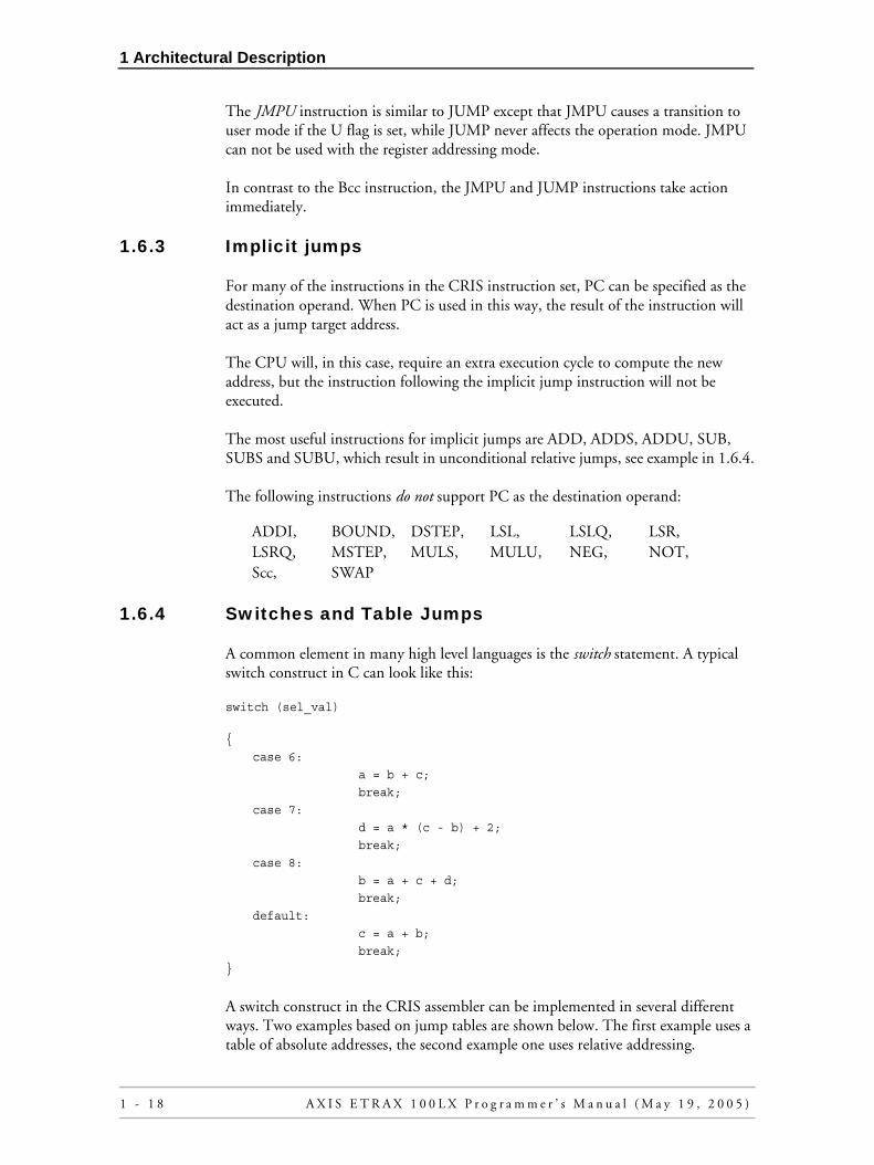
1.6.3 Implicit jumps
For many of the instructions in the CRIS instruction set, PC can be specified as the destination operand. When PC is used in this way, the result of the instruction will act as a jump target address.
The CPU will, in this case, require an extra execution cycle to compute the new address, but the instruction following the implicit jump instruction will not be executed.
The most useful instructions for implicit jumps are ADD, ADDS, ADDU, SUB, SUBS and SUBU, which result in unconditional relative jumps, see example in 1.6.4.
The following instructions do not support PC as the destination operand:
1.6.4 Switches and Table Jumps
A common element in many high level languages is the switch statement. A typical switch construct in C can look like this:
switch (sel_val)
A switch construct in the CRIS assembler can be implemented in several different ways. Two examples based on jump tables are shown below. The first example uses a table of absolute addresses, the second example one uses relative addressing.
ADDI, BOUND, DSTEP, LSL, LSLQ, LSR,LSRQ, MSTEP, MULS, MULU, NEG, NOT,Scc, SWAP
{
case 6:
a = b + c;
break;
case 7:
d = a * (c - b) + 2;
break;
case 8:
b = a + c + d;
break;
default:
c = a + b;
break;
}
1 - 1 8 A X I S E T R A X 1 0 0 L X P r o g r a m m e r ’ s M a n u a l ( M a y 1 9 , 2 0 0 5 )

1 Architectural Description
Example of a switch construct with a table of absolute addresses:
MOVE [sel_val],R0 ; Load selector value to R0.
SUBQ 6,R0 ; Adjust table index by subtracting
; the lowest selector value.
BOUND.D 3,R0 ; Adjust index to point to the default
; case if it is out of range.
JUMP [PC+R0.D] ; Table jump:
.DWORD L6 ; Address to case 6
.DWORD L7 ; Address to case 7
.DWORD L8 ; Address to case 8
.DWORD L_DEF ; Address to default case
L6:
:
(Perform case 6)
:
BA L_END ; Break
Op or NOP ; Delay slot
L7:
:
(Perform case 7)
:
BA L_END ; Break
Op or NOP ; Delay slot
L8:
:
(Perform case 8)
:
BA L_END ; Break
Op or NOP ; Delay slot
L_DEF:
:
(Perform default case)
:
L_END:
A X I S E T R A X 1 0 0 L X P r o g r a m m e r ’ s M a n u a l ( M a y 1 9 , 2 0 0 5 ) 1 - 1 9

1 Architectural Description
Example of a switch construct with a table of relative addresses (this is the model used by the CRIS GNU C Compiler):
MOVE [sel_val],R0 ; Load selector value to R0.
SUBQ 6,R0 ; Adjust table index by subtracting
BOUND.D 3,R0 ; the lowest selector value.
ADDS.W [PC+R0.W],PC ; Adjust index to point to the default
; case if it is out of range.
; Implicit relative table jump:
L_TABLE:
.WORD L6 - L_TABLE ; Address to case 6
.WORD L7 - L_TABLE ; Address to case 7
.WORD L8 - L_TABLE ; Address to case 8
.WORD L_DEF - L_TABLE ; Address to default case
L6:
:
(Perform case 6)
:
BA L_END ; Break
Op or NOP ; Delay slot
L7:
:
(Perform case 7)
:
BA L_END ; Break
Op or NOP ; Delay slot
L8:
:
(Perform case 8)
:
BA L_END ; Break
Op or NOP ; Delay slot
L_DEF:
:
(Perform default case)
:
L_END:
1 - 2 0 A X I S E T R A X 1 0 0 L X P r o g r a m m e r ’ s M a n u a l ( M a y 1 9 , 2 0 0 5 )

1 Architectural Description
1.6.5 Subroutines
The JSR instruction of the CRIS CPU does not automatically push the return address for a subroutine on the stack. Instead, the return address is stored in a special register called the Subroutine Return Pointer (SRP).
For terminal subroutines (subroutines that do not call other subroutines), the return address can be kept in the SRP throughout the subroutine. In this way, the overhead for a subroutine call can be reduced to two single-cycle instructions.
For non-terminal subroutines, the contents of the SRP must be explicitly pushed on the stack. It is preferred that this is done as the first instruction of the subroutine.
This method results in two different ways of returning from a subroutine. Note that the RET instruction is a delayed jump with one delay slot, but the JUMP instruction is performed immediately. See examples below:
Terminal Subroutine
Non-terminal Subroutine
SUB_ENTRY:
: ; Pushing of SRP is not needed.
:
(Perform desired function)
:
:
RET ; Return: Take address from SRP.
Op or NOP ; Delay slot after return.
SUB_ENTRY:
PUSH SRP ; Pushing of SRP on to the stack.
:
(Perform desired function)
:
:
JUMP [SP+] ; Return: Take address from stack.
A X I S E T R A X 1 0 0 L X P r o g r a m m e r ’ s M a n u a l ( M a y 1 9 , 2 0 0 5 ) 1 - 2 1

1 Architectural Description
1.6.6 The JBRC, JIRC and JSRC Subroutine Instructions
The subroutine instruction, Jump to Subroutine with Context (JSRC), adds 4 to the return address stored to the SRP register. This leaves four bytes unused between the JSRC instruction and the return point. These four bytes can, for example, be used for C++ exception handling information.
Figure 1-21 The JSRC Instruction
In the case of immediate addressing, the unused bytes are placed after the immediate value:
Figure 1-22 Immediate Addressing of JSRC
The Jump to Breakpoint Routine with Context (JBRC) instruction, and the Jump to Interrupt Routine with Context (JIRC) instruction act just like JSRC except that instead of storing the return address to the SRP register, JBRC stores the return address to the BRP register, and JIRC stores the return address to the IRP register.
1.7. MMU Support
1.7.1 Overview
To support the Memory Management Unit (MMU) incorporated with the ETRAX 100LX, a number of features have been included in the CRIS architecture:
• The CPU can be in one of two different operation modes: User mode and Supervisor mode. The MMU uses the operation mode to select the appropriate mapping between logical and physical addresses.
• The Bus fault is a mechanism that can interrupt the CPU in any cycle, not only at instruction boundaries. This is needed because the MMU can get a page miss in any cycle. The bus fault mechanism also gives a straightforward way to include single step capability.
Return to here
JSR instruction A
A + 2
Return to here
JSRC instruction
Unused
A
A + 2
A + 6
A
A + 2
A + 6Return to here
JSR instruction
Immediate jumptarget address
Return to here
JSRC instruction
Unused
A
A + 2
A + 6
Immediate jumptarget address
A + 10
1 - 2 2 A X I S E T R A X 1 0 0 L X P r o g r a m m e r ’ s M a n u a l ( M a y 1 9 , 2 0 0 5 )

1 Architectural Description
• With the introduction of the bus fault mechanism, integral read-write operations can not be achieved by just disabling the interrupt. Instead, another method is used, see section 1.13. Integral Read-Write Operations.
The user and supervisor modes have different stack pointers. In both modes, the user mode stack pointer can be referenced as USP, while the currently active stack pointer is referenced as SP (or R14). Thus, in user mode, SP and USP refer to the same register while in supervisor mode, they are separate registers.
Note that the U flag does not indicate the current mode. The U flag is set by bus faults, interrupts, and BREAK instructions depending on the preceding mode. It is used by the instructions that affect the operation mode (JMPU, RBF, RETB, and RETI) to determine which mode will be selected.
The following CRIS instructions are included specifically for MMU support:
• SBFS (Save Bus Fault Status)
• RBF (Return from Bus Fault)
• JMPU (Jump, set user mode if U flag is set)
The SBFS and RBF instructions are used at the entry and exit of the bus fault interrupt routine. They save and restore a 16 byte CPU status record containing the information necessary to resume the operation that was interrupted by the bus fault.
JMPU is intended for return from ordinary interrupt routines where the IRP (or BRP) has been pushed on the stack. By looking at the U flag, JMPU can return to the operation mode that was valid before the interrupt occurred. In the case where the return address from the interrupt routine is kept in the IRP or BRP register, the RETI or RETB instructions will, in the same way, return to the correct operation mode.
This document only describes the CRIS CPU architecture features for MMU support. For information about the ETRAX 100LX Memory Management Unit itself, and for the single step capability, see the ETRAX 100LX Designer’s Reference Manual.
These MMU support features are not available in CRIS implementations prior to the ETRAX 100LX.
A X I S E T R A X 1 0 0 L X P r o g r a m m e r ’ s M a n u a l ( M a y 1 9 , 2 0 0 5 ) 1 - 2 3

1 Architectural Description
1.7.2 Protected registers and flags
A few registers and flags need to be protected from being modified while the CPU is in user mode. The protected registers and flags are:
• IBR (Interrupt Base Register)
• BAR (Breakpoint Address Register)
• M flag (NMI Enable Flag)
• B flag (HW Breakpoint Enable Flag)
• I flag (Interrupt Enable Flag)
An attempt to modify a protected register while in user mode will just be silently denied. It will not cause any exception. The protected registers are readable in both user and supervisor modes.
1.7.3 Transition Between Operation Modes
A transition between the user and supervisor modes can take place for the following reasons:
Transition to User Mode:
• JMPU with the U flag set
• RBF with the U flag set
• RETI with the U flag set
• RETB with the U flag set
Transition to Supervisor Mode:
• System reset
• BREAK instruction
• Interrupt (including NMI and HW break)
• Bus fault
The stack pointers will be automatically exchanged at a transition between the user and supervisor modes.
1 - 2 4 A X I S E T R A X 1 0 0 L X P r o g r a m m e r ’ s M a n u a l ( M a y 1 9 , 2 0 0 5 )

1 Architectural Description
1.7.4 Bus fault sequence
When an external unit (e.g. MMU) signals a Bus Fault, the CPU will interrupt immediately at the end of the CPU clock cycle and enter a Bus Fault sequence.
The Bus Fault sequence is similar to the ordinary interrupt sequence, see section 1.8. Interrupts.The steps in the sequence are:
1 Bus Fault INTA cycle. This cycle will be an idle bus cycle. The following is a pseudo code description of the bus fault INTA cycle operations:
if (current mode == user mode)
{
U flag = 1;
Exchange stack pointers;
}
else
{
U flag = 0;
}
current mode = supervisor mode;
F flag = 1;
hidden CPU status registers = current CPU status;
2 Interrupt vector read cycle. In this cycle the CPU will read the interrupt vector for the Bus Fault interrupt routine. If the bus fault was caused by the single step unit, the interrupt vector number will be 0x20, otherwise it will be 0x2e. If both the MMU and single step bus fault occur at the same time, single step will have priority.
3 Start execution of the Bus Fault interrupt routine at the address given by the interrupt vector.
When entering into the Bus Fault interrupt routine, the internal CPU status is present in hidden CPU status registers. This status has to be saved to the memory using the SBFS instruction as the first instruction in the interrupt routine.
A X I S E T R A X 1 0 0 L X P r o g r a m m e r ’ s M a n u a l ( M a y 1 9 , 2 0 0 5 ) 1 - 2 5

1 Architectural Description
1.7.5 Format of the CPU status record
The format of the CPU status record is as follows:
Figure 1-23
PC Field
First, the PC Field contains the value of PC immediately after the interrupted cycle. For example, if the bus fault occurs on an instruction fetch at address A in a linear instruction stream, the PC field will contain the value A + 2.
Execution State Field
The Execution State Field contains a number of flags that enables the CPU to restart in the correct execution state. The flags are:
Bit Number Flag Name Description
15 - 9 Reserved
These bits are written as 0's by SBFS. To ensure compatibility with future implementations, these bits should not be modified by the SW. If you generate the CPU status record by the SW (not using a status record saved with SBFS), these bits should be set to 0's. The bits are ignored by the current implementation of the RBF instruction.
8 Old F flagThis bit is set according to the status of the F flag immediately after the interrupted cycle (i.e. before it was set by the bus fault). This bit is ignored by the RBF instruction.
7 User mode flagThis bit is set according to the status of the U flag immediately after the interrupted cycle (i.e. before it was modified by the bus fault).
6 Arithmetic extend flagThis bit is set according to the status of the X flag immediately after the interrupted cycle.
5 Unaligned flagSet if the interrupted cycle was the second cycle of an unaligned data read or write.
4 Data cycle flagSet if the interrupted cycle was a data read or write (as opposed to an instruction fetch).
3RETI/RETB delay slot flag
Set if the interrupted cycle was a delay slot of a RETI or RETB instruction that should take effect.
2 Delay slot flagSet if the interrupted cycle was a delay slot of a taken branch, or a delay slot of a RET, RETI or RETB instruction that should take effect.
1 Address prefix flag Set if the interrupted instruction was preceded by an address prefix.
0 Interrupt vector flagSet if the interrupted cycle was an interrupt vector read cycle. This bit is ignored by the RBF instruction.
Table 1-9 Execution State Field Flags
031
An + 4
An + 8
An + 12
An
Interrupted address
PC
Instruction Execution state
Data
1 - 2 6 A X I S E T R A X 1 0 0 L X P r o g r a m m e r ’ s M a n u a l ( M a y 1 9 , 2 0 0 5 )

1 Architectural Description
Instruction field
If the interrupted cycle was a data read or write (i.e. not an instruction fetch), the Instruction Field contains the opcode of the interrupted instruction. In case the interrupted instruction was a MOVEM, the destination field (bit 15-12) of the instruction will hold the register number currently in transfer when the instruction was interrupted.
If the interrupted cycle was an instruction fetch, the instruction field will contain the invalid data that was fetched during the interrupted cycle. In this case, the field will be ignored by the RBF instruction.
Interrupted Address Field
The Interrupted Address Field contains the address of the data entity in transfer during the interrupted cycle. For instruction fetches and for aligned data read/write cycles, this is always the same as the address output from the CPU during the interrupted cycle. But for the second cycle of an unaligned data transfer, this field will contain the address that was output from the CPU during the cycle that came before the interrupted cycle.
Example:
Figure 1-24
An + 3
An + 4
An
AnAn + 1An + 2
Address of the data entity in transfer during the interrupted cycle (i.e. the interrupted address).
This value will be used regardless of whether the bus fault occurs at either An or An + 4.
= Data entity in transfer
A X I S E T R A X 1 0 0 L X P r o g r a m m e r ’ s M a n u a l ( M a y 1 9 , 2 0 0 5 ) 1 - 2 7

1 Architectural Description
Data Field
Finally, the Data Field will have different meaning depending on the type of cycle that was interrupted:
1.7.6 Programming Examples
Go to user mode for the first time:
Bus fault routine:
Disabling interrupt from user mode programs:
In user mode, the I flag is prevented from being changed. This is in general desired to avoid that user mode programs lock out interrupts. If a user mode program needs to disable interrupts, this can be achieved by using the BREAK instruction. You can for example reserve BREAK 0 for this purpose. (The same mechanism can also be used for other more complicated system calls.)
Type of Interrupted Cycle Definition of the Data Field
Instruction fetch cycle, not preceded by an address prefix
The data field contains the ALU result of the previous instruction. This data is ignored by the RBF instruction.
Instruction fetch cycle preceded by an address prefix
The data field contains the address that was calculated by the address prefix.
Aligned data read cycle, or first cycle of an unaligned data read
The data field contains the invalid data that was read in the interrupted cycle. This data is ignored by the RBF instruction.
Second cycle of an unaligned data read
The lower part of the data field contains the valid data that was read in the first cycle of the data read. The upper part of the data field will contain the invalid data read in the interrupted cycle. The RBF instruction will use the lower part and ignore the upper part of the data field.
Data write cycle The data field will contain the data that was going to be written in the interrupted cycle.
Table 1-10 Data Field
MOVE CCR, Rn
OR.W 0x100, Rn
MOVE Rn, CCR ; Set U flag
MOVE user_stack_pointer, USP
JMPU user_mode_program_entry
SBFS [SP=SP-16]
PUSH DCCR
PUSH registers
:
:
POP registers
POP DCCR
RBF [SP+]
1 - 2 8 A X I S E T R A X 1 0 0 L X P r o g r a m m e r ’ s M a n u a l ( M a y 1 9 , 2 0 0 5 )

1 Architectural Description
User mode program:
Breakpoint code:
1.8. Interrupts
The CRIS CPU uses vectorized interrupts that are generated either externally to, or internally by, the ETRAX 100LX. The interrupt acknowledge sequence consists of the following steps:
1 Perform an INTA cycle, where the 8-bit vector number is read from the bus.
2 Store the contents of PC to the Interrupt Return Pointer (IRP). Note that the return address is not automatically pushed on the stack.
3 Read the interrupt vector from the address [IBR + <vector number> * 4].
4 Start the execution at the address pointed to by the interrupt vector.
The Interrupt Base Register (IBR) has bits 31-16 implemented. The remaining bits are always zero.
Figure 1-25 Interrupt Vector Address Calculation
The interrupt acknowledge sequence of the CRIS CPU does not automatically push the condition codes and the interrupt return address on the stack. The interrupt return address is stored in the Interrupt Return Pointer (IRP). If nested interrupts are used, the IRP must be pushed on the stack as the first instruction of the interrupt routine. The Condition Code Register (CCR) must always be pushed at the start of an interrupt routine, and restored at the end.
The Interrupt enable flag is unaffected by the interrupt sequence. However a new interrupt will not be enabled until after the first instruction of the interrupt routine.
:
BREAK 0 ; Jump to breakpoint0_entry
: ; and save return address in BRP.
breakpoint0_entry:
RETB ; Return immediately
DI ; Disable interrupts in the delay slot.
+
31 16 0
7 0
031
IBR
IBR
Vector Number
Vector Number
Interrupt Base Register
Interrupt Vector Address
0 0 0 0 0 0 0 0 0 0 0 0 0 0 0 0
00
00000000
A X I S E T R A X 1 0 0 L X P r o g r a m m e r ’ s M a n u a l ( M a y 1 9 , 2 0 0 5 ) 1 - 2 9

1 Architectural Description
Also, all transfers to and from Special Registers will disable interrupts until the next instruction is executed. In this way, the IRP and CCR or DCCR can always be pushed on the stack before a new interrupt is allowed, see examples on the next page.
Note that the RETI instruction is a delayed jump with one delay slot, but the JMPU instruction is performed directly:
Single Level Interrupts
Nested Interrupts
Interrupts (including NMI and HW break) update the U flag according to the current operating mode, and perform a transition to supervisor mode. The transition will take place in the INTA cycle so that the interrupt vector is read in supervisor mode. An interrupt will also set the F flag.
INT_ENTRY:
PUSH DCCR ; Push condition codes onto the stack.
DI ; Disable interrupts.
SUBQ stack_offset,SP ; Reserve stack for used registers.
MOVEM Rn,[SP] ; Save registers.
:
(Perform desired function)
:
MOVEM [SP+],Rn ; Restore registers.
RETI ; Return: Take address from IRP.
POP DCCR ; Restore condition codes (this is
; placed in the delay slot of the
; RETI instruction).
INT_ENTRY:
PUSH IRP ; Push return address onto the stack.
PUSH DCCR ; Push condition codes onto the stack.
SUBQ stack_offset,SP ; Reserve stack for used registers.
; ← Interrupts are enabled here.
MOVEM Rn,[SP] ; Save registers.
:
(Perform desired function)
:
MOVEM [SP+],Rn ; Restore registers.
POP DCCR ; Restore condition codes.
; ← Interrupts are disabled here
; until after the return from
; interrupt.
JMPU [SP+] ; Return from interrupt.
1 - 3 0 A X I S E T R A X 1 0 0 L X P r o g r a m m e r ’ s M a n u a l ( M a y 1 9 , 2 0 0 5 )

1 Architectural Description
A special case occurs if there is a bus fault in the interrupt vector read cycle. The CPU can handle the bus fault, and a separate bit is set in the CPU status record. The interrupt sequence can, however, not be automatically restarted by the RBF instruction. This case does not have to be considered for MMU functionality because a bus fault on the interrupt vector table would make it impossible to reach the bus fault interrupt routine anyway. For single step, this case has to be checked for and taken care of by the single step SW.
1.8.1 NMI
The Non Maskable Interrupt (NMI) is handled in the same way as the normal interrupt except for the following three differences:
1 The return address is stored in the Breakpoint Return Pointer (BRP) instead of the IRP.
2 The NMI is enabled/disabled by the M flag instead of the I flag. The M flag can be set with the SETF M instruction. Move to CCR/DCCR has no effect. Once set, the M flag can only be cleared by an NMI acknowledge cycle or system reset.
3 The INTA cycle will be an idle bus cycle, and the vector number 0x21 is generated internally in the CPU.
1.9. Software Breakpoints
The CRIS CPU has a breakpoint instruction (BREAK n). This instruction saves the current value of PC in the Breakpoint Return Pointer (BRP) register, and performs a jump to address (IBR + 8*n).
Figure 1-26 Software Breakpoint Address Calculation
1.10. Hardware Breakpoint Mechanism
The CPU contains a hardware breakpoint mechanism. The hardware breakpoint address is loaded in the Breakpoint Address Register (BAR), and the hardware breakpoint mechanism is enabled by setting the Breakpoint enable flag B (see 1-1 and Figure 1-3).
For each CPU read or write cycle, the address is compared with the contents of the BAR register. In order to detect a read or write in the dword (and not just a single
+
31 0
0
031
IBR
IBR
Interrupt Base Register
0 0 0 0 0 0 0 0 0 0 0 0 0 0 0 0
00
00000000
Breakpoint Routine Entry
0
0000
3
n
n
A X I S E T R A X 1 0 0 L X P r o g r a m m e r ’ s M a n u a l ( M a y 1 9 , 2 0 0 5 ) 1 - 3 1

1 Architectural Description
byte) of the address location, bit 1 and 0 are ignored in the comparison. Bit 31 is also ignored in the comparison since that bit handles the cache in the ETRAX 100LX(address bit 31 set will bypass the cache and directly access the main memory).
An address hit is handled in the same way as an NMI with interrupt vector number 0x20, except that a breakpoint hit is not affected by the M flag.
The hardware breakpoint mechanism is disabled after reset.
1.11. Multiply and Divide
1.11.1 General
The ETRAX 100LX implementation of the CRIS CPU has two multiply instructions: Signed Multiply (MULS) and Unsigned Multiply (MULU). For compatibility with CRIS implementations not supporting multiply instructions, multiply operations can also be performed using a sequence of Multiply Step (MSTEP) instructions.
There are no divide instructions, so divide operations are performed by a sequence of Divide Step (DSTEP) instructions.
1.11.2 Multiply using MULS and MULU
The MULS and MULU instructions are fast (2 cycle) multiply operations. The multiply is performed on 32 by 32 bits, giving a 64-bit result. The lower 32 bits are stored to the destination register specified with the instruction, while the upper 32 bits are stored in the Multiply Overflow (MOF) register.
For multiply with byte or word sized operands, the operands are extended to 32 bits before the multiply. Sign extend is used with Signed Multiply (MULS), while zero extend is used with Unsigned Multiply (MULU).
1 - 3 2 A X I S E T R A X 1 0 0 L X P r o g r a m m e r ’ s M a n u a l ( M a y 1 9 , 2 0 0 5 )

1 Architectural Description
1.11.3 Multiply Using MSTEP
In addition to the MULS and MULU instructions, multiply operations can be performed using the MSTEP instruction. The MSTEP instruction does the following:
1 Shifts the destination register one step to the left.
2 If the N flag is set, adds the source operand.
3 Updates the flags.
The example below shows a 16-bit by 16-bit unsigned multiply with 32-bit result:
MUL_BEGIN:
MOVU.W [value1],R0 ; Move first operand to a register,
; and clear the upper 16 bits.
MOVU.W [value2],R1 ; Move second operand to a register.
LSLQ 16,R1 ; Shift left, clear the lower 16 bits
; of the result register, and set the
; N flag according to msb of value2.
MSTEP R0,R1 ; Perform 16 iterations of the MSTEP
MSTEP R0,R1 ; instruction. Each iteration sets
MSTEP R0,R1 ; the N flag for next step.
MSTEP R0,R1
MSTEP R0,R1
MSTEP R0,R1
MSTEP R0,R1
MSTEP R0,R1
MSTEP R0,R1
MSTEP R0,R1
MSTEP R0,R1
MSTEP R0,R1
MSTEP R0,R1
MSTEP R0,R1
MSTEP R0,R1
MSTEP R0,R1 ; The last iteration. The result is in R1.
A X I S E T R A X 1 0 0 L X P r o g r a m m e r ’ s M a n u a l ( M a y 1 9 , 2 0 0 5 ) 1 - 3 3

1 Architectural Description
1.11.4 Divide
Divide operations can be performed using the DSTEP instruction. The DSTEP instruction does the following:
1 Shifts the destination register one step to the left.
2 If the destination register is unsigned-greater-than or equal to the source operand, the source operand is subtracted from the destination register.
16-bit by 16-bit unsigned divide example:
1.12. Extended arithmetic
Extended arithmetic (arithmetic with more than 32 bits) is supported by using the X flag. The X flag is set by the AX (SETF X) instruction, and is cleared by all other instructions.
When the X flag is set, instructions involving an addition or subtraction are modified in the following ways:
DIV_BEGIN:
MOVU.W [num],R1 ; Move numerator to a register,
; and clear the upper 16 bits.
MOVU.W [denom],R0 ; Move denominator to a register.
LSLQ 16,R0 ; Shift left, clear the lower 16 bits
; of the denominator register.
SUBQ 1,R0 ; Subtract one from the denominator.
DSTEP R0,R1 ; Perform 16 iterations of the DSTEP
DSTEP R0,R1 ; instruction.
DSTEP R0,R1
DSTEP R0,R1
DSTEP R0,R1
DSTEP R0,R1
DSTEP R0,R1
DSTEP R0,R1
DSTEP R0,R1
DSTEP R0,R1
DSTEP R0,R1
DSTEP R0,R1
DSTEP R0,R1
DSTEP R0,R1
DSTEP R0,R1
DSTEP R0,R1 ; The last iteration. The quotient is
; in the lower half of R1, and the
; remainder is in the upper half of of R1.
1 - 3 4 A X I S E T R A X 1 0 0 L X P r o g r a m m e r ’ s M a n u a l ( M a y 1 9 , 2 0 0 5 )

1 Architectural Description
1 The C flag is added to the result of an addition, and subtracted from the result of a subtraction. This is valid even if the addition/subtraction result is not the result operand of the instruction.
2 If the result operand is zero, the Z flag will maintain its old value instead of being set.
3 The change of the Z flag behaviour is valid for all instructions that affect the Z flag except:
The addition/subtraction of the C flag affects the following instructions:
The address calculation in addressing mode prefixes is not affected.The AX instruction disables the interrupts until the next instruction to ensure that the X flag is not cleared by an interrupt routine before it is used. Below are two examples of extended arithmetic.
Add a 48-bit signed value contained in R3:R2 to a 64 bit value stored in R1:R0:
Test if a 40-bit value contained in R1:R0 is zero:
1.13. Integral Read-Write Operations
Since a bus fault can interrupt the CPU in any bus cycle (except INTA), it is not possible to ensure the integrity of a piece of code just by disabling the interrupts or by only using instructions that lock out interrupts between them. Instead, integral read-write operations can be implemented by using the Load-locked, Store-conditional principle:
CLEARF,MOVE to CCR/DCCR,POP CCR/DCCR,SETF
ABS, ADD, ADDI, ADDQ, ADDS,ADDU, BOUND, CMP, CMPQ, CMPS,CMPU, DSTEP, MSTEP, NEG, SUB,SUBQ, SUBS, SUBU
EXT_ADD:
ADD.D R2,R0 ; Add the low dwords.
AX ; Set the X flag.
ADDS.W R3,R1 ; Add the upper 16 source bits.
EXT_TEST:
TEST.D R0 ; Test the lower 32 bits.
AX
TEST.B R1 ; Test upper 8 bits.
A X I S E T R A X 1 0 0 L X P r o g r a m m e r ’ s M a n u a l ( M a y 1 9 , 2 0 0 5 ) 1 - 3 5

1 Architectural Description
Start:
Initialize lock;
Read variable;
Modify variable;
Write back variable if and only if the sequence hasn't been interrupted;
Go to Start if write failed;
The F and P flags, and the branch instruction Branch on Write Failed (BWF), are used to test whether the write succeeded or failed. See section 1.2. Flags and Condition Codes.
The F flag is set by the BREAK instruction, when the CPU performs an interrupt acknowledge, or when a bus fault sequence occurs. The P flag is set when a write to memory fails because of broken integrity.
The F and P flags are cleared by the CLEARF instruction regardless of the list of flags. F and P are not affected by the SETF instruction.
A write to memory can be made conditional by setting the X flag in the instruction before the write. This will affect all instructions that write to memory, except SBFS.
Pseudo code for instructions that write to memory will be:
if (F & X)
{
P = 1;
}
else
{
write to memory;
}
The BWF instruction has the action: Branch if P is set. It has the same opcodes as the normal branch instruction, and the condition field of the instruction (bits 15 - 12) is 1111 (binary).
1 - 3 6 A X I S E T R A X 1 0 0 L X P r o g r a m m e r ’ s M a n u a l ( M a y 1 9 , 2 0 0 5 )

1 Architectural Description
.
A code example of how the features can be used to implement a test-and-clear function is shown below:
Still, more complicated things can be done in the loop, as long as the data can be written in one single CPU cycle. With some extra care about where the MMU page boundaries are placed, it is also possible to use write instructions that need several CPU cycles (e.g. unaligned dword writes, or MOVEM instructions).
1.14. Reset
The following registers are initialized after reset:
All other registers have unknown values after reset.
After reset, the ETRAX 100LX CPU starts execution at a particular address depending on the boot method:
START_LOCK:CLEARF ; CLEARF with an empty list will
LOCK_LOOP: MOVE.b [memory_location], R0 ; clear F, P and X flags.
AX ; Save data in R0 for future analysis
CLEAR.b [memory_location] ; Make the clear conditional.
BWF LOCK_LOOP ; Loop back if clear failed.
CLEARF ; Use delay slot to
; reinitialize F and P flags.
Register Value (hex)
VR <version number>
CCR 0000
DCCR 00000000
IBR 00000000
Table 1-11 Registers Initialized After Reset
Register Value (hex)
PROM 80000002
Net 380000f0
Parallel port 380000f0
Serial port 380000f4
Table 1-12 Boot Methods
A X I S E T R A X 1 0 0 L X P r o g r a m m e r ’ s M a n u a l ( M a y 1 9 , 2 0 0 5 ) 1 - 3 7

1 Architectural Description
1.15. Version Identification
Different versions of the CRIS CPU can be identified by reading the Version Register (VR). The version register is an 8-bit read-only register that contains the CPU version number. The contents of the CRIS VR Register are:
Value Chip Name Part No Note
0 ETRAX-1 13425
1 ETRAX-2 13576
2 ETRAX-3 13873
3 ETRAX-4 14517
4, 5, 6, 7 Reserved for future chips in the ETRAX-1 family.
8 ETRAX 100 version 1 15822
9 ETRAX 100 version 2 16284
10 ETRAX 100LX E1 17511
11 ETRAX 100LX E2 17854
11 ETRAX 100LX E3 18816
11 ETRAX 100LX E3 19322 Lead (Pb) free.
12, 13, 14, 15 Reserved for future chips in the ETRAX 100LX family.
16 - 255 Not assigned.
Table 1-13 CRIS VR Register
1 - 3 8 A X I S E T R A X 1 0 0 L X P r o g r a m m e r ’ s M a n u a l ( M a y 1 9 , 2 0 0 5 )
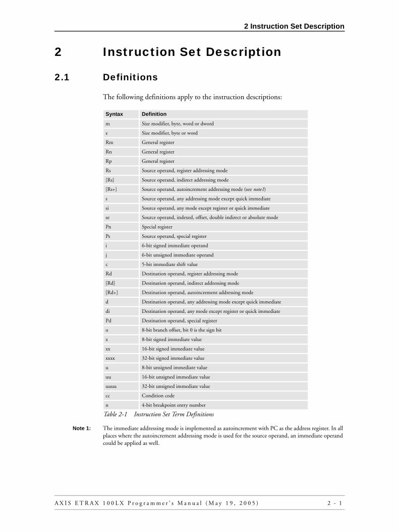
2 Instruction Set Description
2 Instruction Set Description
2.1 Definitions
The following definitions apply to the instruction descriptions:
Note 1: The immediate addressing mode is implemented as autoincrement with PC as the address register. In all places where the autoincrement addressing mode is used for the source operand, an immediate operand could be applied as well.
Syntax Definition
m Size modifier, byte, word or dword
z Size modifier, byte or word
Rm General register
Rn General register
Rp General register
Rs Source operand, register addressing mode
[Rs] Source operand, indirect addressing mode
[Rs+] Source operand, autoincrement addressing mode (see note1)
s Source operand, any addressing mode except quick immediate
si Source operand, any mode except register or quick immediate
se Source operand, indexed, offset, double indirect or absolute mode
Pn Special register
Ps Source operand, special register
i 6-bit signed immediate operand
j 6-bit unsigned immediate operand
c 5-bit immediate shift value
Rd Destination operand, register addressing mode
[Rd] Destination operand, indirect addressing mode
[Rd+] Destination operand, autoincrement addressing mode
d Destination operand, any addressing mode except quick immediate
di Destination operand, any mode except register or quick immediate
Pd Destination operand, special register
o 8-bit branch offset, bit 0 is the sign bit
x 8-bit signed immediate value
xx 16-bit signed immediate value
xxxx 32-bit signed immediate value
u 8-bit unsigned immediate value
uu 16-bit unsigned immediate value
uuuu 32-bit unsigned immediate value
cc Condition code
n 4-bit breakpoint entry number
Table 2-1 Instruction Set Term Definitions
A X I S E T R A X 1 0 0 L X P r o g r a m m e r ’ s M a n u a l ( M a y 1 9 , 2 0 0 5 ) 2 - 1

2 Instruction Set Description
For a description of how the flags are affected, the following definitions apply:
Note 2: See section 1.2. Flags and Condition Codes for details.
Instructions, register specifications, condition code specifications, and size modifiersmay be written in upper or lower case. Upper case is used throughout this manual todistinguish instructions from normal text.
2.2 Instruction Set Summary
2.2.1 Size ModifiersMany of the CRIS instructions can operate on the three different data types byte (8 bits), word (16 bits) and dword (32 bits). The size of the operation or operand is indicated by a size modifier added to the instruction. The size modifiers are:
- flag not affected
0 flag cleared
1 flag set
* flag affected according to the result of the operation (see note2)
Table 2-2 Definitions for how flags are affected
Name Description Size modifier
Byte 8-bit integer .B
Word 16-bit integer .W
Dword 32-bit integer or address .D
Table 2-3 Size Modifiers
2 - 2 A X I S E T R A X 1 0 0 L X P r o g r a m m e r ’ s M a n u a l ( M a y 1 9 , 2 0 0 5 )

2 Instruction Set Description
2.2.2 Addressing Modes
The addressing modes of the CRIS CPU are described in table 2-4 below. For adetailed description of each addressing mode, refer to section 1.5. Addressing Modes.
Assembler syntax Addressing mode
i , j Quick immediate
Rn Register
Pn Special register
[Rn] Indirect
[Rn+] Autoincrement
x , u Byte immediate
xx , uu Word immediate
xxxx , uuuu Dword immediate
[Rn+Rm.s] Indexed
[Rp=Rn+Rm.s] Indexed with assign
[Rn+[Rm].m] Indirect offset
[Rn+[Rm+].m] Autoincrement offset
[Rn+x] Immediate byte offset
[Rn+xx] Immediate word offset
[Rn+xxxx] Immediate dword offset
[Rp=Rn+[Rm].m] Indirect offset with assign
[Rp=Rn+[Rm+].m] Autoincrement offset with assign
[Rp=Rn+x] Immediate Byte offset with assign
[Rp=Rn+xx] Immediate Word offset with assign
[Rp=Rn+xxxx] Immediate dword offset with assign
[[Rn]] Double indirect
[[Rn+]] Double indirect with autoincrement
[uuuu] Absolute
Table 2-4 Addressing Modes
A X I S E T R A X 1 0 0 L X P r o g r a m m e r ’ s M a n u a l ( M a y 1 9 , 2 0 0 5 ) 2 - 3

2 Instruction Set Description
2.2.3 Data Transfers
The data transfer instructions for the CRIS CPU are shown in table 2-5 below. Thetwo predefined assembler macros POP and PUSH are also shown in the table.
Instruction Flag operation Description
F P U M B I X N Z V C
CLEAR.m d - - - - - - 0 - - - - Clear destination operand
MOVE.m s,Rd - - - - - - 0 * * 0 0 Move from source to general register
MOVE.m Rs,di - - - - - - 0 - - - - Move from general register to memory
MOVE(Pd == CCR/DCCR)
s,Pd * * * - * * 0 * * * * Move from source to special register
MOVE(Pd != CCR/DCCR)
s,Pd - - - - - - 0 - - - - Move from source to special register
MOVE Ps,d - - - - - - 0 - - - - Move from special register to destination
MOVEM Rs,di - - - - - - 0 - - - - Move multiple registers to memory
MOVEM si,Rd - - - - - - 0 - - - - Move from memory to multiple registers
MOVEQ i,Rd - - - - - - 0 * * 0 0 Move 6-bit signed immediate
MOVS.z s,Rd - - - - - - 0 * * 0 0 Move with sign extend
MOVU.z s,Rd - - - - - - 0 0 * 0 0 Move with zero extend
POP Rd - - - - - - 0 * * 0 0 Pop register from stack
POP Pd - - - - - - 0 - - - - Pop special register from stack
PUSH Rs - - - - - - 0 - - - - Push register onto stack
PUSH Ps - - - - - - 0 - - - - Push special register onto stack
SBFS di - - - - - - 0 - - - - Save bus fault status
SWAP <opt.> Rd - - - - - - 0 * * 0 0 Swap operand bits
Table 2-5 Data Transfer Instructions
2 - 4 A X I S E T R A X 1 0 0 L X P r o g r a m m e r ’ s M a n u a l ( M a y 1 9 , 2 0 0 5 )

2 Instruction Set Description
2.2.4 Arithmetic Instructions
The arithmetic instructions for the CRIS CPU are described in table 2-6 below. Notethat the TEST instruction is a predefined assembler macro for register operands, butis a real instruction with other addressing modes.
With Indexed and Offset addressing modes, instructions that normally have twooperands exist in a 2-operand and a 3-operand form:
Example:
ADD.W [SP+8],R4 ; Add [SP+8] to R4 and store the result in R4.
ADD.W [SP+8],R4,R5 ; Add [SP+8] to R4 and store the result in R5.
; R4 is not changed
Instruction Flag operation Description
F P U M B I X N Z V C
ABS Rs,Rd - - - - - - 0 * * 0 0 Absolute value
ADD.m s,Rd - - - - - - 0 * * * * Add source to destination register
ADDI Rs.m,Rd - - - - - - 0 - - - - Add scaled index to base
ADDQ j,Rs - - - - - - 0 * * * * Add 6-bit unsigned immediate
ADDS.z s,Rd - - - - - - 0 * * * * Add sign extended source to register
ADDU.z s,Rd - - - - - - 0 * * * * Add zero extended source to register
BOUND.m s,Rd - - - - - - 0 * * 0 0 Adjust table index (unsigned min)
CMP.m s,Rd - - - - - - 0 * * * * Compare source to register
CMPQ i,Rd - - - - - - 0 * * * * Compare with 6-bit signed immediate
CMPS.z si,Rd - - - - - - 0 * * * * Compare with sign extended source
CMPU.z si,Rd - - - - - - 0 * * * * Compare with zero extended source
DSTEP Rs,Rd - - - - - - 0 * * 0 0 Divide step
MSTEP Rs,Rd - - - - - - 0 * * 0 0 Multiply step
MULS.m Rs,Rd - - - - - - 0 * * * 0 Signed multiply
MULU.m Rs,Rd - - - - - - 0 * * * 0 Unsigned multiply
NEG.m Rs,Rd - - - - - - 0 * * * * Negate (2’s complement)
SUB.m s,Rd - - - - - - 0 * * * * Subtract source from register
SUBQ j,Rd - - - - - - 0 * * * * Subtract 6-bit unsigned immediate
SUBS.z s,Rd - - - - - - 0 * * * * Subtract with sign extended source
SUBU.z s,Rd - - - - - - 0 * * * * Subtract with zero extended source
TEST.m s - - - - - - 0 * * 0 0 Compare operand with 0
Table 2-6 Arithmetic Instructions
A X I S E T R A X 1 0 0 L X P r o g r a m m e r ’ s M a n u a l ( M a y 1 9 , 2 0 0 5 ) 2 - 5

2 Instruction Set Description
2.2.5 Logical Instructions
The logical instructions for the CRIS CPU are described in table 2-7 below. WithIndexed and Offset addressing modes, instructions that normally have two operandsexist in a 2-operand and a 3-operand form.
2.2.6 Shift Instructions
The shift instructions for the CRIS CPU are shown in table 2-8 below. When theshift count is contained in a register, the 6 least significant bits of the register are usedas an unsigned shift count.
2.2.7 Bit Test Instructions
The bit test instructions for the CRIS CPU are shown in table 2-9 below. The BTSTand BTSTQ instructions set the N flag according to the selected bit in thedestination register. The Z flag is set if the selected bit and all bits to the right of thedestination register are zero. When the bit number is contained in a register, the 6least significant bits of the register are used as an unsigned bit number.
Instruction Flag operation Description
F P U M B I X N Z V C
AND.m s,Rd - - - - - - 0 * * 0 0 Bitwise logical AND
ANDQ i,Rd - - - - - - 0 * * 0 0 AND with 6-bit signed immediate
NOT Rd - - - - - - 0 * * 0 0 Logical NOT (1’s complement)
OR.m s,Rd - - - - - - 0 * * 0 0 Bitwise logical OR
ORQ i,Rd - - - - - - 0 * * 0 0 OR with 6-bit signed immediate
XOR Rs,Rd - - - - - - 0 * * 0 0 Bitwise Exclusive OR
Table 2-7 Logical Instructions
Instruction Flag operation Description
F P U M B I X N Z V C
ASR.m Rs,Rd - - - - - - 0 * * 0 0 Right shift Rd with sign fill
ASRQ c,Rd - - - - - - 0 * * 0 0 Right shift Rd with sign fill
LSL.m Rs,Rd - - - - - - 0 * * 0 0 Left shift Rd with zero fill
LSLQ c,Rd - - - - - - 0 * * 0 0 Left shift Rd with zero fill
LSR.m Rs,Rd - - - - - - 0 * * 0 0 Right shift Rd with zero fill
LSRQ c,Rd - - - - - - 0 * * 0 0 Right shift Rd with zero fill
Table 2-8 Shift Instructions
Instruction Flag operation Description
F P U M B I X N Z V C
BTST Rs,Rd - - - - - - 0 * * 0 0 Test bit Rs in register Rd
BTSTQ c,Rd - - - - - - 0 * * 0 0 Test bit c in register Rd
LZ Rs,Rd - - - - - - 0 0 * 0 0 Number of leading zeroes
Table 2-9 Bit Test Instructions
2 - 6 A X I S E T R A X 1 0 0 L X P r o g r a m m e r ’ s M a n u a l ( M a y 1 9 , 2 0 0 5 )

2 Instruction Set Description
2.2.8 Condition Code Manipulation Instructions
The condition code manipulation instructions for the CRIS CPU are shown in table2-9 below. The predefined assembler macros EI, DI, and AX are also shown.
2.2.9 Jump and Branch Instructions
The jump and branch instructions of the CRIS CPU are shown in table 2-11 below.The predefined assembler macros RET and RETI are also shown. Note that the Bcc,RET and RETI instructions have a delayed effect, see section 1.6.1 ConditionalBranch.
Note 3: The JBRC, JIRC and JSRC instructions will add four bytes to the return address stored to either SRP, IRP or BRP. This leaves four Bytes unused between the JSRC/JIRC/JBRC instruction and the return point. This can be used to enhance C++ exception support.
Instruction Flag operation Description
F P U M B I X N Z V C
AX - - - - - - 1 - - - - Arithmetic extend (SETF X)
CLEARF <list> 0 0 - - * * 0 * * * * Clear flags in list
DI 0 0 - - - 0 0 - - - - Disable interrupts (CLEARF I)
EI - - - - - 1 0 - - - - Enable interrupts (SETF I)
Scc Rd - - - - - - 0 - - - - Set register according to cc
SETF <list> - - - * * * * * * * * Set flags in list
Table 2-10 Condition Code Manipulation Instructions
Instruction Flag operation Description
F P U M B I X N Z V C
Bcc o - - - - - - 0 - - - - Conditional relative branch
Bcc xx - - - - - - 0 - - - - Branch with 16-bit offset
BREAK n 1 - * - - - 0 - - - - Breakpoint
JBRC s - - - - - - 0 - - - - Jump to breakpoint routine, see note 3
JIR s - - - - - - 0 - - - - Jump to interrupt routine
JIRC s - - - - - - 0 - - - - Jump to interrupt routine, see note 3
JMPU si - - - - - - 0 - - - - Jump and set operation mode
JSR s - - - - - - 0 - - - - Jump to subroutine
JSRC s - - - - - - 0 - - - - Jump to subroutine, see note 3
JUMP s - - - - - - 0 - - - - Jump
RBF si - - * - - - * - - - - Return from bus fault
RET - - - - - - 0 - - - - Return from subroutine
RETB - - - - - - 0 - - - - Return from breakpoint routine
RETI - - - - - - 0 - - - - Return from interrupt routine
Table 2-11 Jump and Branch Instructions
A X I S E T R A X 1 0 0 L X P r o g r a m m e r ’ s M a n u a l ( M a y 1 9 , 2 0 0 5 ) 2 - 7

2 Instruction Set Description
2.2.10 No Operation Instruction
The CRIS CPU also has a no operation instruction, NOP.
2.3 Instruction Format Summary
2.3.1 Summary of Quick Immediate Mode Instructions
Note 4: The (s.) field is the sign bit of the offset.
Note 5: BDAP is the base + offset addressing mode prefix.
Instruction Flag operation Description
F P U M B I X N Z V C
NOP - - - - - - 0 - - - - No operation
Table 2-12 No Operation Instruction
Operation Operand 2 Mode Opcode Operand 1 Note
Bcc o Condition 0 0 0 0 Offset (7 bits) s. note4
(BDAP o,Rs) Base 0 0 0 1 Signed displacement (8 bits) note5
ADDQ j,Rd Dest. reg. 0 0 1 0 0 0 Unsigned immediate (6 bits)
MOVEQ i,Rd Dest. reg. 0 0 1 0 0 1 Signed immediate (6 bits)
SUBQ j,Rd Dest. reg. 0 0 1 0 1 0 Unsigned immediate (6 bits)
CMPQ i,Rd Dest. reg. 0 0 1 0 1 1 Signed immediate (6 bits)
ANDQ i,Rd Dest. reg. 0 0 1 1 0 0 Signed immediate (6 bits)
ORQ i,Rd Dest. reg. 0 0 1 1 0 1 Signed immediate (6 bits)
BTSTQ c,Rd Dest. reg. 0 0 1 1 1 0 0 Bit number (5 bits)
ASRQ c,Rd Dest. reg. 0 0 1 1 1 0 1 Shift value (5 bits)
LSLQ c,Rd Dest. reg. 0 0 1 1 1 1 0 Shift value (5 bits)
LSRQ c,Rd Dest. reg. 0 0 1 1 1 1 1 Shift value (5 bits)
Table 2-13 Quick Immediate Mode Instructions
2 - 8 A X I S E T R A X 1 0 0 L X P r o g r a m m e r ’ s M a n u a l ( M a y 1 9 , 2 0 0 5 )

2 Instruction Set Description
2.3.2 Summary of Register Instructions with Variable Size
Note 6: ADDI cannot have PC as base.
Note 7: BIAP is the base + index addressing mode prefix.
z:size:
0 Byte
zz: size:
00 Byte
1 Word 01 Word
10 Dword
Table 2-14 Variable Size
Operation Operand 2 Mode Opcode Size Operand 1 Note
ADDU.z Rs,Rd Dest. reg. 0 1 0 0 0 0 0 z Source reg.
ADDS.z Rs,Rd Dest. reg. 0 1 0 0 0 0 1 z Source reg.
MOVU.z Rs,Rd Dest. reg. 0 1 0 0 0 1 0 z Source reg.
MOVS.z Rs,Rd Dest. reg. 0 1 0 0 0 1 1 z Source reg.
SUBU.z Rs,Rd Dest. reg. 0 1 0 0 1 0 0 z Source reg.
SUBS.z Rs,Rd Dest. reg. 0 1 0 0 1 0 1 z Source reg.
LSL.m Rs,Rd Dest. reg. 0 1 0 0 1 1 z z Source reg.
ADDI Rs.m,Rd Index 0 1 0 1 0 0 z z Base note6
MULS.m Rs,Rd Dest. reg. 1 0 0 1 0 0 z z Source reg.
MULU.m Rs,Rd Dest. reg. 1 1 0 1 0 0 z z Source reg.
(BIAP Rs.m,Rd) Index 0 1 0 1 0 1 z z Base note7
NEG.m Rs,Rd Dest. reg. 0 1 0 1 1 0 z z Source reg.
BOUND.m Rs,Rd Index 0 1 0 1 1 1 z z Bound
ADD.m Rs,Rd Dest. reg. 0 1 1 0 0 0 z z Source reg.
MOVE.m Rs,Rd Dest. reg. 0 1 1 0 0 1 z z Source reg.
SUB.m Rs,Rd Dest. reg. 0 1 1 0 1 0 z z Source reg.
CMP.m Rs,Rd Dest. reg. 0 1 1 0 1 1 z z Source reg.
AND.m Rs,Rd Dest. reg. 0 1 1 1 0 0 z z Source reg.
OR.m Rs,Rd Dest. reg. 0 1 1 1 0 1 z z Source reg.
ASR.m Rs,Rd Dest. reg. 0 1 1 1 1 0 z z Source reg.
LSR.m Rs,Rd Dest. reg. 0 1 1 1 1 1 z z Source reg.
Table 2-15 Register Instructions with Variable Size
A X I S E T R A X 1 0 0 L X P r o g r a m m e r ’ s M a n u a l ( M a y 1 9 , 2 0 0 5 ) 2 - 9

2 Instruction Set Description
2.3.3 Summary of Register Instructions with Fixed Size
Note 8: When destination is PC, and source is SRP, BRP or IRP, this instruction implements the RET, RETB or RETI instruction. MOVE from special registers p0, p4 and p8 are used as CLEAR. The size of the clear depends of the specified number for the special register.
Operation Operand 2 Mode Opcode Size Operand 1 Note
BTST Rs,Rd Dest. reg. 0 1 0 0 1 1 1 1 Source reg.
NOP 0 0 0 0 0 1 0 1 0 0 0 0 1 1 1 1
Scc Rd Condition 0 1 0 1 0 0 1 1 Dest. reg.
(Reserved) Dest. reg. 0 1 0 1 0 1 1 1 Source reg.
SETF <list> M B I X 0 1 0 1 1 0 1 1 N Z V C
CLEARF <list> - B I X 0 1 0 1 1 1 1 1 N Z V C
MOVE Rs,Pd Special reg. 0 1 1 0 0 0 1 1 Source reg.
MOVE Ps,Rd Special reg. 0 1 1 0 0 1 1 1 Dest. reg. note8
ABS Rs,Rd Dest. reg. 0 1 1 0 1 0 1 1 Source reg.
DSTEP Rs,Rd Dest. reg. 0 1 1 0 1 1 1 1 Source reg.
LZ Dest. reg 0 1 1 1 0 0 1 1 Source reg.
SWAP<opt.> Rd N W B R 0 1 1 1 0 1 1 1 Dest. reg.
NOT Rd 1 0 0 0 0 1 1 1 0 1 1 1 Dest. reg.
XOR Rs,Rd Dest. reg. 0 1 1 1 1 0 1 1 Source reg.
MSTEP Rs,Rd Dest. reg. 0 1 1 1 1 1 1 1 Source reg.
Table 2-16 Register instructions with fixed size
2 - 1 0 A X I S E T R A X 1 0 0 L X P r o g r a m m e r ’ s M a n u a l ( M a y 1 9 , 2 0 0 5 )

2 Instruction Set Description
2.3.4 Summary of Indirect Instructions with Variable Size
Note 9: BDAP is the base + offset addressing mode prefix.
m: mode:0 Indirect mode
1 Autoincrement mode
Table 2-17
z:size:
0 Byte
zz: size:
00 Byte
1 Word 01 Word
10 Dword
Table 2-18 Mode and Variable Size
Operand Operand 2 Mode Opcode Size Operand 1 Note
ADDU.z [ ],Rd Dest. reg. 1 m 0 0 0 0 0 z Source
ADDS.z [ ],Rd Dest. reg. 1 m 0 0 0 0 1 z Source
MOVU.z [ ],Rd Dest. reg. 1 m 0 0 0 1 0 z Source
MOVS.z [ ],Rd Dest. reg. 1 m 0 0 0 1 1 z Source
SUBU.z [ ],Rd Dest. reg. 1 m 0 0 1 0 0 z Source
SUBS.z [ ],Rd Dest. reg. 1 m 0 0 1 0 1 z Source
CMPU.z [ ],Rd Dest. reg. 1 m 0 0 1 1 0 z Source
CMPS.z [ ],Rd Dest. reg. 1 m 0 0 1 1 1 z Source
(BDAP [ ],Rd) Base 1 m 0 1 0 1 z z Source note9
(Reserved) Operand 2 1 m 0 1 1 0 z z Operand 1
BOUND.m [ ],Rd index 1 m 0 1 1 1 z z Bound
ADD.m [ ],Rd Dest. reg. 1 m 1 0 0 0 z z Source
MOVE.m [ ],Rd Dest. reg. 1 m 1 0 0 1 z z Source
SUB.m [ ],Rd Dest. reg. 1 m 1 0 1 0 z z Source
CMP.m [ ],Rd Dest. reg. 1 m 1 0 1 1 z z Source
AND.m [ ],Rd Dest. reg. 1 m 1 1 0 0 z z Source
OR.m [ ],Rd Dest. reg. 1 m 1 1 0 1 z z Source
TEST.m [ ] 0 0 0 0 1 m 1 1 1 0 z z Source
MOVE.m Rs,[ ] Source reg. 1 m 1 1 1 1 z z Dest.
Table 2-19 Indirect Instructions with Variable Size
A X I S E T R A X 1 0 0 L X P r o g r a m m e r ’ s M a n u a l ( M a y 1 9 , 2 0 0 5 ) 2 - 1 1

2 Instruction Set Description
2.3.5 Summary of Indirect Instructions with Fixed Size
Note 10: DIP is the double indirection addressing mode prefix
Note 11: MOVE from special registers p0, p4 and p8 are used as CLEAR. The size of the clear depends of the specified number for the special register.
m: mode:0 Indirect mode
1 Autoincrement mode
Table 2-20 Mode
Operation Operand 2 Mode Opcode Size Operand 1 Note
JBRC/JSRC/JIRC
[ ] Special reg. - 8 1 m 0 1 0 0 1 1 Source
JUMP [ ] 0 0 0 0 1 m 0 1 0 0 1 1 Source
JMPU [ ] 1 0 0 0 1 m 0 1 0 0 1 1 Source
JSR/JIR [ ] Special reg. 1 m 0 1 0 0 1 1 Source
BREAK n 1 1 1 0 1 0 0 1 0 0 1 1 n
(DIP [ ]) 0 0 0 0 1 m 0 1 0 1 1 1 Source note10
JBRC/JSRC/JIRC
Rs Special reg. - 8 1 0 0 1 1 0 1 1 Source reg.
JUMP/JSR/JIR Rs 0 0 0 0 1 0 0 1 1 0 1 1 Source reg.
Bcc [PC+] Condition 1 m 0 1 1 1 1 1 1 1 1 1
MOVE [ ],Pd Special reg. 1 m 1 0 0 0 1 1 Source
MOVE Ps,[ ] Special reg. 1 m 1 0 0 1 1 1 Dest. note11
(Reserved) Dest. reg. 1 m 1 0 1 0 1 1 Source
(Reserved) Dest. reg. 1 m 1 0 1 1 1 1 Source
RBF [ ] 0 0 1 1 1 m 1 1 0 0 1 1 Source
SBFS [ ] 0 0 1 1 1 m 1 1 0 1 1 1 Dest.
MOVEM [ ],Rd Dest. reg. 1 m 1 1 1 0 1 1 Source
MOVEM Rs,[ ] Source reg. 1 m 1 1 1 1 1 1 Dest.
Table 2-21 Indirect Instructions with Fixed Size
2 - 1 2 A X I S E T R A X 1 0 0 L X P r o g r a m m e r ’ s M a n u a l ( M a y 1 9 , 2 0 0 5 )

2 Instruction Set Description
2.4 Addressing Mode Prefix Formats
The instruction format of the Addressing mode prefix words are shown below.
Indexed Addressing Mode Prefix Word:
Offset Addressing Mode Prefix Word, Immediate byte Offset:
Offset Addressing Mode Prefix Word, General Case:
Double Indirect and Absolute Addressing Mode Prefix Word:
Size:
00 Index register is pointer to byte
01 Index register is pointer to word
10 Index register is pointer to dword
Table 2-22 Size for Indexed Addressing Mode Prefix Word
Mode (md):0 Indirect offset addressing mode
1 Autoincrement or immediate offset addressing modes.
Size:
00 Offset is byte
01 Offset is word
10 Offset is dword
Table 2-23 Mode and Size for Offset Addressing Mode Prefix Word
Mode (md):
0 Double indirect addressing mode
1 Double indirect with autoincrement, or Absolute addressing mode.
Table 2-24 Mode for Double Indirect and Absolute Addressing Mode Prefix Word
015
0 SizeIndex register 1 1 0 Base register1 0
015
0 Signed offsetBase register 1 0 0
015
1 SizeBase register 1 md 0 Offset1 0
015
1 1 md 0 Source1 0 00 00 1 1
A X I S E T R A X 1 0 0 L X P r o g r a m m e r ’ s M a n u a l ( M a y 1 9 , 2 0 0 5 ) 2 - 1 3

2 Instruction Set Description
2 - 1 4 A X I S E T R A X 1 0 0 L X P r o g r a m m e r ’ s M a n u a l ( M a y 1 9 , 2 0 0 5 )

3 Instructions in Alphabetical Order
3 INSTRUCTIONS IN ALPHABETICAL ORDER
In this section, all the instructions of the CRIS CPU are described in alphabetical order. Each description contains the following information:
Assembler syntax: Shows the assembler syntax for the instruction. Operands, addressing modes and size modifiers are described using the definitions shown in section section 2.1 Definitions. Note that instructions, operands etc. may be written in upper or lower case.
Size: Lists the different data sizes for the instruction.
Operation: Describes the instruction in a form similar to the C programming language. Different data sizes are shown with the “type cast” method used in the C language. The behavior of the flags is usually not shown.
Description: A text description of the instruction.
Flags affected: Shows which flags that are affected by the instruction. The detailed behavior of the flags is shown insection 1.2. Flags and Condition Codes.
Instruction format: Shows the instruction format. The format of the Addressing mode prefix word for the complex addressing modes is not shown here. This can be found in section 1.5. Addressing Modes, and in section 2.4 Addressing Mode Prefix Formats.
A X I S E T R A X 1 0 0 L X P r o g r a m m e r ’ s M a n u a l ( M a y 1 9 , 2 0 0 5 ) 3 - 1

3 Instructions in Alphabetical Order
Assembler syntax: ABS Rs,Rd
Size: Dword
Operation: if (Rs < 0)
{
Rd = -Rs;
}
else
{
Rd = Rs;
}
Description: The absolute value of the contents of the source register is stored in the destination register. The size of the operation is dword.
flags affected: F P U M B I X N Z V C- - - - - - 0 * * 0 0
Instruction format:
Note 1: If the source operand is 0x80000000, the result of the operation will be 0x80000000
ABS Absolute Value ABS
015
0 1Destination (Rd) 0 1 1 Source (Rs)0 1 1
3 - 2 A X I S E T R A X 1 0 0 L X P r o g r a m m e r ’ s M a n u a l ( M a y 1 9 , 2 0 0 5 )

3 Instructions in Alphabetical Order
Assembler syntax: ADD.m s,Rd
Size: Byte, word, or dword
Operation: (m)Rd += (m)s;
Description: The source data is added to the destination register. The size of the operation is m. The rest of the destination register is not affected.
flags affected: F P U M B I X N Z V C- - - - - - 0 * * * *
Instruction format:(register, indirect, or auto-
increment addressing modes)
Instruction format:(complex addressing modes)
ADD Add ADD2-operand 2-operand
Mode:
01 Register addressing mode
10 Indirect addressing mode
11 Autoincrement addressing mode
Size:
00 Byte
01 Word
10 Dword
015
Mode SizeDestination (Rd) 0 1 Source (Rs)0 0
Mode (md):
0 Indexed, offset, double indirect, absolute addressing modes. The Operand1 field must be the same as destination field (Rd).
1 Indexed with assign, offset with assign addressingmodes. The Operand1 field selects the register in which to store the address of the source operand.
Size:
00 Byte
01 Word
10 Dword
015
Addressing mode prefix word (s)
1 SizeDestination (Rd) 0 md 1 Operand10 0
A X I S E T R A X 1 0 0 L X P r o g r a m m e r ’ s M a n u a l ( M a y 1 9 , 2 0 0 5 ) 3 - 3

3 Instructions in Alphabetical Order
Assembler syntax: ADD.m se,Rn,Rd
Size: Byte, word, or dword
Operation: (m)Rd = (m)se + (m)Rn;
Description: The memory source data is added to the contents of a general register, and the result is stored in the destination register. The size of the operation is m. The rest of the destination register is not affected.
flags affected: F P U M B I X N Z V C- - - - - - 0 * * * *
Instruction format:
ADD Add ADD3-operand 3-operand
Size:
00 Byte
01 Word
10 Dword
015
Addressing mode prefix word (se)
1 SizeRegister (Rn) 00 1 Destination (Rd)0 0
3 - 4 A X I S E T R A X 1 0 0 L X P r o g r a m m e r ’ s M a n u a l ( M a y 1 9 , 2 0 0 5 )

3 Instructions in Alphabetical Order
Assembler syntax: ADDI Rs.m,Rd
Size: Rs is a pointer to byte, word or dword. The size of the operation is dword.
Operation: Rd += Rs * sizeof(m);
Description: Add a scaled index to a base. The contents of the source register is shifted left 0, 1 or 2 positions, depending on the size modifier m, and is then added to the destination register. The size of the operation is dword.
flags affected: F P U M B I X N Z V C- - - - - - 0 - - - -
Instruction format:
Note 2: PC is not allowed to be the base register.
ADDI Add index ADDI
Size:
00 Rs is pointer to Byte
01 Rs is pointer to Word
10 Rs is pointer to Dword
015
0 SizeIndex (Rs) 1 1 0 Base (Rd)0 0
A X I S E T R A X 1 0 0 L X P r o g r a m m e r ’ s M a n u a l ( M a y 1 9 , 2 0 0 5 ) 3 - 5

3 Instructions in Alphabetical Order
Assembler syntax: ADDQ j,Rd
Size: Source data is 6-bit. The size of the operation is dword
Operation: Rd += j;
Description: A 6-bit immediate value, zero extended to dword, is added to the destination register.
flags affected: F P U M B I X N Z V C- - - - - - 0 * * * *
Instruction format:
ADDQ Add quick ADDQ
015
0 Destination (Rd) 0 0 1 Unsigned immediate0 0
3 - 6 A X I S E T R A X 1 0 0 L X P r o g r a m m e r ’ s M a n u a l ( M a y 1 9 , 2 0 0 5 )

3 Instructions in Alphabetical Order
Assembler syntax: ADDS.z s,Rd
Size: Source size is byte or word. Operation size is dword
Operation: Rd += (z)s;
Description: The source data is sign extended from z to dword, and then added to the destination register.
flags affected: F P U M B I X N Z V C- - - - - - 0 * * * *
Instruction format:(register, indirect, or auto-
increment addressingmodes)
Instruction format:(complex addressing modes)
ADDS Add with sign extend ADDS2-operand 2-operand
Mode:
01 Register addressing mode
10 Indirect addressing mode
11 Autoincrement addressing mode
Size (z):0 Byte source operand
1 Word source operand
015
Mode 1Destination (Rd) 0 0 Source (s)0 0 z
Mode (md):
0 Indexed, offset, double indirect, or absolute addressing modes. The Operand1 field must be the same as the Destination field (Rd).
1 Indexed with assign, or offset with assign addressing modes. The Operand1 field selects the register in which to store the address of the source operand.
Size (z):0 Byte source operand
1 Word source operand
015
Addressing mode prefix word (s)
1 1Destination (Rd) 0 md 0 Operand10 0 z
A X I S E T R A X 1 0 0 L X P r o g r a m m e r ’ s M a n u a l ( M a y 1 9 , 2 0 0 5 ) 3 - 7

3 Instructions in Alphabetical Order
Assembler syntax: ADDS.z se,Rn,Rd
Size: Source size is byte or word. Operation size is dword
Operation: Rd = (z)se + Rn;
Description: The source data is sign extended from z to dword, and then added to the contents of a general register. The result is stored in the destination register.
flags affected: F P U M B I X N Z V C- - - - - - 0 * * * *
Instruction format:
ADDS Add with sign extend ADDS3-operand 3-operand
Size (z):0 Byte source operand
1 Word source operand
015
Addressing mode prefix word (se)
1 1Register (Rn) 0 0 0 Destination (Rd)0 0 z
3 - 8 A X I S E T R A X 1 0 0 L X P r o g r a m m e r ’ s M a n u a l ( M a y 1 9 , 2 0 0 5 )

3 Instructions in Alphabetical Order
Assembler syntax: ADDU.z s,Rd
Size: Source size is byte or word. Operation size is dword
Operation: Rd += (unsigned z)s;
Description: The source data is zero extended from z to dword, and then added to the destination register.
flags affected: F P U M B I X N Z V C- - - - - - 0 * * * *
Instruction format:(register, indirect, or auto-
increment addressingmodes)
Instruction format:(complex addressing modes)
ADDU Add with zero extend ADDU2-operand 2-operand
Mode:
01 Register addressing mode
10 Indirect addressing mode
11 Autoincrement addressing mode
Size (z):0 Byte source operand
1 Word source operand
015
Mode 0Destination (Rd) 0 0 Source (s)0 0 z
Mode (md):
0 Indexed, offset, double indirect, or absolute addressing modes. The Operand1 field must be the same as the Destination field (Rd).
1 Indexed with assign, or offset with assign addressing modes. The Operand1 field selects the register in which to store the address of the source operand.
Size (z):0 Byte source operand
1 Word source operand
015
Addressing mode prefix word (s)
1 0Destination (Rd) 0 md 0 Operand10 0 z
A X I S E T R A X 1 0 0 L X P r o g r a m m e r ’ s M a n u a l ( M a y 1 9 , 2 0 0 5 ) 3 - 9

3 Instructions in Alphabetical Order
Assembler syntax: ADDU.z se,Rn,Rd
Size: Source size is byte or word. Operation size is dword
Operation: Rd = (unsigned z)se + Rn;
Description: The source data is zero extended from z to dword, and is then added to the contents of a general register. The result is stored in the destination register.
flags affected: F P U M B I X N Z V C- - - - - - 0 * * * *
Instruction format:
ADDU Add with sign extend ADDU3-operand 3-operand
Size (z):0 Byte source operand
1 Word source operand
015
Addressing mode prefix word (se)
1 0Register (Rn) 0 0 0 Destination (Rd)0 0 z
3 - 10 A X I S E T R A X 1 0 0 L X P r o g r a m m e r ’ s M a n u a l ( M a y 1 9 , 2 0 0 5 )

3 Instructions in Alphabetical Order
Assembler syntax: AND.m s,Rd
Size: Byte, word, or dword
Operation: (m)Rd &= (m)s;
Description: A logical AND is performed between the source operand and the destination register. The size of the operation is m. The rest of the destination register is not affected.
flags affected: F P U M B I X N Z V C- - - - - - 0 * * 0 0
Instruction format:(register, indirect, or auto-
increment addressingmodes)
Instruction format:(complex addressing modes)
AND Logical AND AND2-operand 2-operand
Mode:
01 Register addressing mode
10 Indirect addressing mode
11 Autoincrement addressing mode
Size:
00 Byte
01 Word
10 Dword
015
Mode SizeDestination (Rd) 1 1 Source (s)0 0
Mode (md):
0 Indexed, offset, double indirect, or absolute addressing modes. The Operand1 field must be the same as the Destination field (Rd).
1 Indexed with assign, or offset with assign addressing modes. The Operand1 field selects the register in which to store the address of the source operand.
Size:
00 Byte
01 Word
10 Dword
015
Addressing mode prefix word (s)
1 SizeDestination (Rd) 1 md 1 Operand10 0
A X I S E T R A X 1 0 0 L X P r o g r a m m e r ’ s M a n u a l ( M a y 1 9 , 2 0 0 5 ) 3 - 11

3 Instructions in Alphabetical Order
Assembler syntax: AND.m se,Rn,Rd
Size: Byte, word, or dword
Operation: (m)Rd = (m)se & (m)Rn;
Description: A logical AND is performed between the source operand and the contents of a general register. The result is stored in the destination register. The size of the operation is m. The rest of the destination register is not affected.
flags affected: F P U M B I X N Z V C- - - - - - 0 * * 0 0
Instruction format:
AND Logical AND AND3-operand 3-operand
Size:
00 Byte
01 Word
10 Dword
015
Addressing mode prefix word (se)
1 SizeRegister (Rn) 1 0 1 Destination (Rd)0 0
3 - 12 A X I S E T R A X 1 0 0 L X P r o g r a m m e r ’ s M a n u a l ( M a y 1 9 , 2 0 0 5 )

3 Instructions in Alphabetical Order
Assembler syntax: ANDQ i,Rd
Size: Source data is 6-bit. Operation size is dword.
Operation: Rd &= i;
Description: A logical AND is performed between a 6-bit immediate value, sign extended to dword, and the destination register.
flags affected: F P U M B I X N Z V C- - - - - - 0 * * 0 0
Instruction format:
ANDQ Logical AND quick ANDQ
015
0 Destination (Rd) 1 0 1 Signed immediate0 0
A X I S E T R A X 1 0 0 L X P r o g r a m m e r ’ s M a n u a l ( M a y 1 9 , 2 0 0 5 ) 3 - 13

3 Instructions in Alphabetical Order
Assembler syntax: ASR.m Rs,Rd
Size: Byte, word, or dword
Operation: (m)Rd >>= (Rs & 63);
Description: The destination register is right shifted the number of steps specified by the 6 least significant bits of the source register. The shift is performed with sign extend. The size of the operation is m. The rest of the destination register is not affected.
flags affected: F P U M B I X N Z V C- - - - - - 0 * * 0 0
Instruction format:
Note 3: A shift of 32 bits or more will produce the same result as shifting the destination register 31 bits.
ASR Arithmetic shift right ASR
Size:
00 Byte
01 Word
10 Dword
015
0 SizeDestination (Rd) 1 1 1 Source (Rs)0 1
3 - 14 A X I S E T R A X 1 0 0 L X P r o g r a m m e r ’ s M a n u a l ( M a y 1 9 , 2 0 0 5 )

3 Instructions in Alphabetical Order
Assembler syntax: ASRQ c,Rd
Size: Dword
Operation: Rd >>= c;
Description: The destination register is right shifted the number of steps specified by the 5-bit immediate value. The shift is performed with sign extend. The size of the operation is dword.
flags affected: F P U M B I X N Z V C- - - - - - 0 * * 0 0
Instruction format:
ASRQ Arithmetic shift right quick ASRQ
015
0 1Destination (Rd) 1 0 1 Shift value0 1
A X I S E T R A X 1 0 0 L X P r o g r a m m e r ’ s M a n u a l ( M a y 1 9 , 2 0 0 5 ) 3 - 15

3 Instructions in Alphabetical Order
Assembler syntax: AX
Size: -
Operation: X = 1;
Description: Arithmetic extension prefix. Set X flag. Disable interrupts until next instruction. This is a predefined assembler macro equivalent to SETF X.
flags affected: F P U M B I X N Z V C- - - - - - 1 - - - -
Instruction format:
AX Arithmetic extension AX
015
0 10 11 0 00 1 1 0 0 0 0 1 0
3 - 16 A X I S E T R A X 1 0 0 L X P r o g r a m m e r ’ s M a n u a l ( M a y 1 9 , 2 0 0 5 )

3 Instructions in Alphabetical Order
Assembler syntax: Bcc oBcc xx
Size: Byte, Word
Operation: if (cc)
{
PC += offset;offset = o or xx
}
Description: If the condition cc is true, the offset is sign extended to dword and is added to PC. Interrupts are disabled until after the next instruction. The Bcc instruction is a delayed branch instruction, with one delay slot (see section 1.6.1 Conditional Branch). Valid instructions for the delay slot are all instructions except:
• Bcc
• BREAK/JBRC/JIR/JIRC/JMPU/JSR/JSRC/JUMP
• RET/RETB/RETI
• Instructions using addressing prefixes
• Immediate addressing other than Quick Immediate
The value of PC used for the address calculation is the address of the instruction after the branch instruction.Condition Codes:
(continued)
Bcc Branch conditionally Bcc
A X I S E T R A X 1 0 0 L X P r o g r a m m e r ’ s M a n u a l ( M a y 1 9 , 2 0 0 5 ) 3 - 17

3 Instructions in Alphabetical Order
flags affected: F P U M B I X N Z V C- - - - - - 0 - - - -
Instruction format:(8-bit offset)
Offset: Bits 7 - 1 of the offset represent bits 7 - 1 in the actual address increment/decrement. Bit 0 in the offset field is used as a sign bit in the computed offset. Bit 0 of the instruction field is bit 8 of the computed offset, and bit 0 of the computed offset is always 0.
Instruction format:(16-bit offset)
Offset: Bits 15 - 1 make up the actual address increment/decrement. Bit 0 must always be 0 because of the word alignment of instructions.
Code Alt Condition Encoding Boolean function
CC HS Carry Clear 0000 C
CS LO Carry Set 0001 C
NE Not Equal 0010 Z
EQ Equal 0011 Z
VC Overflow Clear 0100 V
VS Overflow Set 0101 V
PL Plus 0110 N
MI Minus 0111 N
LS Low or Same 1000 C + Z
HI High 1001 C * Z
GE Greater or Equal 1010 N * V + N * V
LT Less Than 1011 N * V + N * V
GT Greater Than 1100 N * V * Z + N * V * Z
LE Less or Equal 1101 Z + N * V + N * V
A Always True 1110 1
WF Write Failed 1111 P
Table 3-1 Condition Codes
015
0 Condition 0 0 0 Offset (o)
015
1 1Condition 1 1 0 1 1 1 1
Offset 0
1 1 1
3 - 18 A X I S E T R A X 1 0 0 L X P r o g r a m m e r ’ s M a n u a l ( M a y 1 9 , 2 0 0 5 )

3 Instructions in Alphabetical Order
Assembler syntax: BOUND.m s,Rd
Size: Source is byte, word or dword. Operation is dword
Operation: if ((unsigned)Rd > (unsigned m)s){
Rd = (unsigned m)s;}
Description: This is a bounding instruction for adjusting branch indexes in switch statements. If the unsigned contents of the dword index (destination) register is greater than the unsigned bound (source) data, the bound data (zero extended to dword) is loaded to the index register. Otherwise, the index register is unaffected.
flags affected: F P U M B I X N Z V C- - - - - - 0 * * 0 0
Instruction format:(register, indirect, or auto-
increment addressingmodes)
Note 4: PC is not allowed to be the Index (Rd) operand.
(continued)
BOUND Adjust index to bound BOUND2-operand 2-operand
Mode:
01 Register addressing mode
10 Indirect addressing mode
11 Autoincrement addressing mode
Size:
00 Byte
01 Word
10 Dword
015
Mode SizeIndex (Rd) 1 0 Bound (s)1 1
A X I S E T R A X 1 0 0 L X P r o g r a m m e r ’ s M a n u a l ( M a y 1 9 , 2 0 0 5 ) 3 - 19

3 Instructions in Alphabetical Order
Instruction format:(complex addressing modes)
Note 5: PC is not allowed to be the Index (Rd) operand.
Mode (md):
0 Indexed, offset, double indirect, or absolute addressing modes. The Operand1 field must be the same as index field (Rd).
1 Indexed with assign, or offset with assign addressing modes. The Operand1 field selects the register in which to store the address of the source operand.
Size:
00 Byte
01 Word
10 Dword
015
Addressing mode prefix word (se)
1 SizeIndex (Rd) 1 md 0 Operand111
3 - 20 A X I S E T R A X 1 0 0 L X P r o g r a m m e r ’ s M a n u a l ( M a y 1 9 , 2 0 0 5 )

3 Instructions in Alphabetical Order
Assembler syntax: BOUND.m se,Rn,Rd
Size: Source is byte, word or dword. Operation is dword
Operation: if ((unsigned) Rn > (unsigned m)se){
Rd = (unsigned m)se;}else{
Rd = Rn;}
Description: This is a bounding instruction for adjusting branch indexes in switch statements. If the unsigned contents of the dword index (Rn) register is greater than the unsigned bound (source) data, the bound data (zero extended to dword) is loaded to the destination register. Otherwise, the contents of the index register are loaded to the destination register.
flags affected: F P U M B I X N Z V C- - - - - - 0 * * 0 0
Instruction format:
Note 6: PC is not allowed to be the Destination (Rd) operand.
BOUND Adjust index to bound BOUND3-operand 3-operand
Size:
00 Byte
01 Word
10 Dword
015
Addressing mode prefix word (se)
1 SizeIndex (Rn) 1 0 0 Destination (Rd)1 1
A X I S E T R A X 1 0 0 L X P r o g r a m m e r ’ s M a n u a l ( M a y 1 9 , 2 0 0 5 ) 3 - 21

3 Instructions in Alphabetical Order
Assembler syntax: BREAK n
Size: -
Operation: BRP = PC;PC = IBR + (8*n);
Description: Breakpoint. This instruction saves PC to the Breakpoint Return Pointer (BRP), and then performs a jump to address:
(IBR + (8 * n)).
BREAK updates the U flag according to the current operating mode, and performs a transition to supervisor mode. It also sets the F flag.
flags affected: F P U M B I X N Z V C1 - * - - - 0 - - - -
Instruction format:
BREAK Breakpoint BREAK
015
1 11 1 0 0 n0 0 1 1 1 0
3 - 22 A X I S E T R A X 1 0 0 L X P r o g r a m m e r ’ s M a n u a l ( M a y 1 9 , 2 0 0 5 )

3 Instructions in Alphabetical Order
Assembler syntax: BTST Rs,Rd
Size: Dword
Operation: N = Bit number (Rs & 31) of Rd;Z = ((Bit numbers 0 to (Rs & 31) of Rd) == 0);
Description: The N flag is set according to the selected bit in the destination register. The Z flag is set if the selected bit and all bits to the right of it are zero. The bit number is selected by the 5 least significant bits of the source register. The destination register is not affected.
flags affected: F P U M B I X N Z V C- - - - - - 0 * * 0 0
Instruction format:
BTST Bit test BTST
015
0 1Destination (Rd) 0 1 0 Source (Rs)1 1 1
A X I S E T R A X 1 0 0 L X P r o g r a m m e r ’ s M a n u a l ( M a y 1 9 , 2 0 0 5 ) 3 - 23

3 Instructions in Alphabetical Order
Assembler syntax: BTSTQ c,Rd
Size: Dword
Operation: N = Bit number c of Rd;Z = ((Bit numbers 0 to c of Rd) == 0);
Description: The N flag is set according to the selected bit in the destination register. The Z flag is set if the selected bit and all bits to the right of it are zero. The bit number is selected by the 5-bit immediate value. The destination register is not affected.
flags affected: F P U M B I X N Z V C- - - - - - 0 * * 0 0
Instruction format:
BTSTQ Bit test quick BTSTQ
015
0 0Destination (Rd) 1 0 1 Bit number (c)0 1
3 - 24 A X I S E T R A X 1 0 0 L X P r o g r a m m e r ’ s M a n u a l ( M a y 1 9 , 2 0 0 5 )

3 Instructions in Alphabetical Order
Assembler syntax: CLEAR.m d
Size: Byte, word, or dword
Operation: (m)d = 0;
Description: The destination is cleared to all zeroes. The size of the operation is m. Interrupts are disabled until the next instruction has been executed.
flags affected: F P U M B I X N Z V C- - - - - - 0 - - - -
Instruction format:(register, indirect, or auto-
increment addressingmodes)
Note 7: If PC is used as the destination operand, the resulting jump will have a delayed effect with one delay slot.
(continued)
CLEAR Clear CLEAR
Mode:
01 Register addressing mode
10 Indirect addressing mode
11 Autoincrement addressing mode
Size:
00 Byte
01 Word
10 Dword
015
0 1Size 0 0 1 Destination (d)1 0 1 Mode
A X I S E T R A X 1 0 0 L X P r o g r a m m e r ’ s M a n u a l ( M a y 1 9 , 2 0 0 5 ) 3 - 25

3 Instructions in Alphabetical Order
Instruction format:(complex addressing modes)
Mode (md):
0 Indexed, offset, double indirect, or absolute addressing modes. The contents of the Operand1 field are ignored.
1 Indexed with assign, or offset with assign addressing modes. The Operand1 field selects the register in which to store the address of the source operand.
Size:
00 Byte
01 Word
10 Dword
015
Addressing mode prefix word (d)
1 1Size 0 md 1 Operand11 0 0 0 1
3 - 26 A X I S E T R A X 1 0 0 L X P r o g r a m m e r ’ s M a n u a l ( M a y 1 9 , 2 0 0 5 )

3 Instructions in Alphabetical Order
Assembler syntax: CLEARF <list of flags>
Size: -
Operation: Selected flags = 0;X = 0;F = 0;P = 0;
Description: The specified flags are cleared to 0. The F, P, and X flags are always cleared even if they are not in the list supplied with CLEARF. The M and U flags are not affected. Interrupts are disabled until the next instruction has been executed.
When the list of flags contains more than one flag, the flags may be written in any order. The CLEARF instruction accepts an empty list of flags.
Examples:
flags affected: F P U M B I X N Z V C0 0 - - * * 0 * * * *
Instruction format:
CLEARF Clear flags CLEARF
CLEARF CVX ; Clear F, P, C, V and X flags.
CLEARF ; Clear F, P, and X flags.
CLEARF BI ; Clear F, P, B, I and X flags.
CLEARF FP ; Clear F, P and X flags.
015
0 1M 1 1 0 N1 1 1 V Z B I X C
A X I S E T R A X 1 0 0 L X P r o g r a m m e r ’ s M a n u a l ( M a y 1 9 , 2 0 0 5 ) 3 - 27

3 Instructions in Alphabetical Order
Assembler syntax: CMP.m s,Rd
Size: Byte, word, or dword
Operation: (m)Rd - (m)s;
Description: The source data is subtracted from the destination register, and the flags are set accordingly. The size of the operation is m. The destination register is not updated.
flags affected: F P U M B I X N Z V C- - - - - - 0 * * * *
Instruction format:(register, indirect, or auto-
increment addressingmodes)
Instruction format:(complex addressing modes)
CMP Compare CMP
Mode:
01 Register addressing mode
10 Indirect addressing mode
11 Autoincrement addressing mode
Size:
00 Byte
01 Word
10 Dword
015
Mode SizeDestination (Rd) 0 1 Source (Rs)1 1
Mode (md):
0 Indexed, offset, double indirect, or absolute addressing modes. The contents of the Operand1 field are ignored.
1 Indexed with assign, or offset with assign addressing modes. The Operand1 field selects the register in which to store the address of the source operand in.
Size:
00 Byte
01 Word
10 Dword
015
Addressing mode prefix word (s)
1 SizeDestination (Rd) 0 md 1 Operand11 1
3 - 28 A X I S E T R A X 1 0 0 L X P r o g r a m m e r ’ s M a n u a l ( M a y 1 9 , 2 0 0 5 )
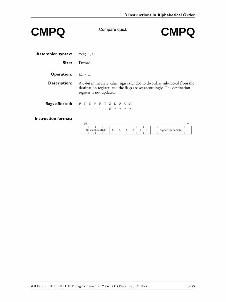
3 Instructions in Alphabetical Order
Assembler syntax: CMPQ i,Rd
Size: Dword
Operation: Rd - i;
Description: A 6-bit immediate value, sign extended to dword, is subtracted from the destination register, and the flags are set accordingly. The destination register is not updated.
flags affected: F P U M B I X N Z V C- - - - - - 0 * * * *
Instruction format:
CMPQ Compare quick CMPQ
015
0 Destination (Rd) 0 0 1 Signed immediate1 1
A X I S E T R A X 1 0 0 L X P r o g r a m m e r ’ s M a n u a l ( M a y 1 9 , 2 0 0 5 ) 3 - 29

3 Instructions in Alphabetical Order
Assembler syntax: CMPS.z si,Rd
Size: Source size is byte or word. Operation size is dword
Operation: Rd - (z)si;
Description: The source data, sign extended to dword, is subtracted from the destination register, and the flags are set accordingly. The destination register is not updated.
flags affected: F P U M B I X N Z V C- - - - - - 0 * * * *
Instruction format:(indirect or autoincrement
addressing modes)
Instruction format:(complex addressing modes)
CMPS Compare with sign extend CMPS
Mode (md):0 Indirect addressing mode
1 Autoincrement addressing mode
Size (z):0 Byte source operand
1 Word source operand
015
1 1Destination (Rd) 0 md 0 Source (si)1 1 z
Mode (md):
0 Indexed, offset, double indirect, or absolute addressing modes. The contents of the Operand1 field are ignored.
1 Indexed with assign, or offset with assign addressing modes. The Operand1 field selects the register in which to store the address of the source operand.
Size (z):0 Byte source operand
1 Word source operand
015
Addressing mode prefix word (si)
1 zDestination (Rd) 0 md 0 Operand11 1 1
3 - 30 A X I S E T R A X 1 0 0 L X P r o g r a m m e r ’ s M a n u a l ( M a y 1 9 , 2 0 0 5 )

3 Instructions in Alphabetical Order
Assembler syntax: CMPU.z si,Rd
Size: Source size is byte or word. Operation size is dword
Operation: Rd - (unsigned z)si;
Description: The source data, zero extended to dword, is subtracted from the destination register, and the flags are set accordingly. The destination register is not updated.
flags affected: F P U M B I X N Z V C- - - - - - 0 * * * *
Instruction format:(indirect or autoincrement
addressing modes)
Instruction format:(complex addressing modes)
CMPU Compare with zero extend CMPU
Mode (md):0 Indirect addressing mode
1 Autoincrement addressing mode
Size (z):0 Byte source operand
1 Word source operand
015
1 0Destination (Rd) 0 md 0 Source (si)1 1 z
Mode (md):
0 Indexed, offset, double indirect, or absolute addressing modes. The contents of the Operand1 field are ignored.
1 Indexed with assign, or offset with assign addressing modes. The Operand1 field selects the register in which to store the address of the source operand.
Size (z):0 Byte source operand
1 Word source operand
015
Addressing mode prefix word (si)
1 zDestination (Rd) 0 md 0 Operand11 1 0
A X I S E T R A X 1 0 0 L X P r o g r a m m e r ’ s M a n u a l ( M a y 1 9 , 2 0 0 5 ) 3 - 31

3 Instructions in Alphabetical Order
Assembler syntax: DI
Size: -
Operation: I = 0;X = 0;F = 0;P = 0;
Description: Disable interrupts. This is a predefined assembler macro equivalent to CLEARF I.
flags affected: F P U M B I X N Z V C0 0 - - - 0 0 - - - -
Instruction format:
DI Disable interrupts DI
015
0 10 1 1 0 01 1 1 0 0 0 1 0 0
3 - 32 A X I S E T R A X 1 0 0 L X P r o g r a m m e r ’ s M a n u a l ( M a y 1 9 , 2 0 0 5 )

3 Instructions in Alphabetical Order
Assembler syntax: DSTEP Rs,Rd
Size: Dword
Operation: Rd <<= 1;if ((unsigned)Rd >= (unsigned)Rs){
Rd -= Rs;}
Description: This is a divide-step operation, which performs one iteration of an iterative divide operation. The destination operand is shifted one step to the left. If the shifted destination operand is unsigned-greater-than or equal to the source operand, the source operand is subtracted from the shifted destination operand. The size of the operation is dword.
flags affected: F P U M B I X N Z V C- - - - - - 0 * * 0 0
Instruction format:
Note 8: PC is not allowed to be the destination operand (Rd).
DSTEP Divide step DSTEP
015
0 1Destination (Rd) 0 1 1 Source (Rs)1 1 1
A X I S E T R A X 1 0 0 L X P r o g r a m m e r ’ s M a n u a l ( M a y 1 9 , 2 0 0 5 ) 3 - 33

3 Instructions in Alphabetical Order
Assembler syntax: EI
Size: -
Operation: I = 1;X = 0;
Description: Enable interrupts after the next instruction. This is a predefined assembler macro equivalent to SETF I.
flags affected: F P U M B I X N Z V C- - - - - 1 0 - - - -
Instruction format:
EI Enable interrupts EI
015
0 10 1 1 0 00 1 1 0 0 0 1 0 0
3 - 34 A X I S E T R A X 1 0 0 L X P r o g r a m m e r ’ s M a n u a l ( M a y 1 9 , 2 0 0 5 )

3 Instructions in Alphabetical Order
Assembler syntax: JBRC s
Size: Dword
Operation: BRP = PC + 4;PC = s;
Description: Jump to interrupt routine. The Breakpoint Return Pointer (BRP) is loaded with the contents of the program counter (PC). PC is then loaded with the contents of the source operand. Interrupts are disabled until the next instruction has been executed. The size of the operation is dword.
The JBRC instruction skips one dword at the PC and thus reserves one dword for context information, see section 1.6.6 The JBRC, JIRC and JSRC Subroutine Instructions. The context information is not used by the instruction.
The jump takes place immediately after the JBRC instruction.
The value of PC loaded to BRP is the address of the instruction after the JBRC instruction.
flags affected: F P U M B I X N Z V C- - - - - - 0 - - - -
Instruction format:(register addressing mode)
(continued)
JBRC Jump to beakpoint routine, with context information JBRC
015
1 110 0 Source (s)0 1 1
Context information (low)
Context information (high)
0 0 1 1
A X I S E T R A X 1 0 0 L X P r o g r a m m e r ’ s M a n u a l ( M a y 1 9 , 2 0 0 5 ) 3 - 35

3 Instructions in Alphabetical Order
Instruction format:(indirect or autoincrement
addressing modes)
Note 9: In immediate addressing mode, the immediate address is placed before the context information.
Instruction format:(complex addressing modes)
Mode (md):0 Indirect addressing mode
1 Autoincrement addressing mode
015
1 11 md 0 Source (s)0 0 1
Context information (low)
Context information (high)
0 0 1 1
Mode (md):
0 Indexed, offset, double indirect, or absolute addressing modes. The contents of the Operand1 field are ignored.
1 Indexed with assign, offset with assign addressing modes. The Operand1 field selects the register in which to store the address of the source operand.
Context information (high)
015
Addressing mode prefix word (s)
1 11 md 0 Source (s)0 0 1
Context information (low)
10 1 0
3 - 36 A X I S E T R A X 1 0 0 L X P r o g r a m m e r ’ s M a n u a l ( M a y 1 9 , 2 0 0 5 )

3 Instructions in Alphabetical Order
Assembler syntax: JIR s
Size: Dword
Operation: IRP = PC;PC = s;
Description: Jump to interrupt routine. The interrupt return pointer (IRP) is loaded with the contents of the program counter (PC). PC is then loaded with the contents of the source operand. Interrupts are disabled until the next instruction has been executed. The size of the operation is dword.
The jump takes place immediately after the JIR instruction.
The value of PC loaded to IRP is the address of the instruction after the JIR instruction.
flags affected: F P U M B I X N Z V C- - - - - - 0 - - - -
Instruction format:(register addressing mode)
Instruction format:(indirect or autoincrement
addressing modes)
(continued)
JIR Jump to interrupt routine JIR
015
1 11 1 0 0 Source (s)0 1 1 0 1 0
Mode (md):0 Indirect addressing mode
1 Autoincrement addressing mode
015
1 11 1 md 0 Source (s)0 0 1 0 1 0
A X I S E T R A X 1 0 0 L X P r o g r a m m e r ’ s M a n u a l ( M a y 1 9 , 2 0 0 5 ) 3 - 37

3 Instructions in Alphabetical Order
Instruction format:(complex addressing modes)
Mode (md):
0 Indexed, offset, double indirect, or absolute addressing modes. The contents of the Operand1 field are ignored.
1 Indexed with assign, offset with assign addressing modes. The Operand1 field selects the register in which to store the address of the source operand.
015
Addressing mode prefix word (s)
1 11 0 md 0 Operand10 1 0 1 0 1
3 - 38 A X I S E T R A X 1 0 0 L X P r o g r a m m e r ’ s M a n u a l ( M a y 1 9 , 2 0 0 5 )

3 Instructions in Alphabetical Order
Assembler syntax: JIRC s
Size: Dword
Operation: IRP = PC;PC = s;
Description: Jump to interrupt routine. The interrupt return pointer (IRP) is loaded with the contents of the program counter (PC). PC is then loaded with the contents of the source operand. Interrupts are disabled until the next instruction has been executed. The size of the operation is dword.
The JIRC instruction skips one dword at the PC and thus reserves one dword for context information, see section 1.6.6 The JBRC, JIRC and JSRC Subroutine Instructions. The context information is not used by the instruction.
The jump takes place immediately after the JIRC instruction.
The value of PC loaded to IRP is the address of the instruction after the JIRC instruction.
flags affected: F P U M B I X N Z V C- - - - - - 0 - - - -
Instruction format:(register addressing mode)
(continued)
JIRC Jump to interrupt routine, with context information JIRC
015
1 11 0 0 Source (s)0 1 1 0
Context information (low)
0 0 1
Context information (high)
A X I S E T R A X 1 0 0 L X P r o g r a m m e r ’ s M a n u a l ( M a y 1 9 , 2 0 0 5 ) 3 - 39

3 Instructions in Alphabetical Order
Instruction format:(indirect or autoincrement
addressing modes)
Note 10: In immediate addressing mode, the immediate address is placed before the context information.
Instruction format:(complex addressing modes)
Mode (md):0 Indirect addressing mode
1 Autoincrement addressing mode
015
1 11 md 0 Source (s)0 0 1 0
Context information (low)
0 0 1
Context information (high)
Mode (md):
0 Indexed, offset, double indirect, or absolute addressing modes. The contents of the Operand1 field are ignored.
1 Indexed with assign, or offset with assign addressing modes. The Operand1 field selects the register in which to store the address of the source operand.
Context information (high)
015
Addressing mode prefix word (s)
1 11 md 0 Source (s)0 0 1
Context information (low)
0 0 0 1
3 - 40 A X I S E T R A X 1 0 0 L X P r o g r a m m e r ’ s M a n u a l ( M a y 1 9 , 2 0 0 5 )

3 Instructions in Alphabetical Order
Assembler syntax: JMPU si
Size: Dword
Operation: PC = si;
Description: The JMPU instruction is similar to the normal JUMP instruction. The difference is that JMPU will look at the U flag, and make a transition to user mode if U is set. If U is not set, the CPU will stay in the current mode. JMPU is intended to be used instead of JUMP when returning from interrupt routines where IRP (or BRP) have been pushed on to the stack. Interrupts are disabled until the next instruction has been executed.
JMPU only supports indirect and complex addressing modes. Register addressing mode is not supported.
flags affected: F P U M B I X N Z V C- - - - - - 0 - - - -
Instruction format:(indirect, or auto-
increment addressingmodes)
Instruction format:(complex addressing modes)
JMPU Jump, set user mode if U flag is set JMPU
Mode (md):0 Indirect addressing mode
1 Autoincrement addressing mode
015
1 11 1 md 0 Source00 1 0 0 0
Mode (md):
0 Indexed, offset, double indirect, and absolute addressing modes. Operand1 field should be 0011 (binary).
1 Indexed with assign, and offset with assign addressing modes. Operand1 field selects the register in which to store the source address.
015
Addressing mode prefix word (s)
1 1 md 0 Operand100 1 00 0 1 1
A X I S E T R A X 1 0 0 L X P r o g r a m m e r ’ s M a n u a l ( M a y 1 9 , 2 0 0 5 ) 3 - 41

3 Instructions in Alphabetical Order
Assembler syntax: JSR s
Size: Dword
Operation: SRP = PC;PC = s;
Description: Jump to subroutine. The subroutine return pointer (SRP) is loaded with the contents of the program counter (PC). PC is then loaded with the contents of the source operand. Interrupts are disabled until the next instruction has been executed. The size of the operation is dword.
The jump takes place immediately after the JSR instruction.
The value of PC loaded to SRP is the address of the instruction after the JSR instruction.
flags affected: F P U M B I X N Z V C- - - - - - 0 - - - -
Instruction format:(register addressing mode)
Instruction format:(indirect or autoincrement
addressing modes)
(continued)
JSR Jump to subroutine JSR
015
1 11 10 0 Source (s)0 1 1 0 1 1
Mode (md):0 Indirect addressing mode
1 Autoincrement addressing mode
015
1 11 1md 0 Source (s)0 0 1 0 1 1
3 - 42 A X I S E T R A X 1 0 0 L X P r o g r a m m e r ’ s M a n u a l ( M a y 1 9 , 2 0 0 5 )

3 Instructions in Alphabetical Order
Instruction format:(complex addressing modes)
Mode (md):
0 Indexed, offset, double indirect, or absolute addressing modes. The contents of the Operand1 field are ignored.
1 Indexed with assign, or offset with assign addressing modes. The Operand1 field selects the register in which to store the address of the source operand.
015
Addressing mode prefix word (s)
1 11 md 0 Destination (Rd)0 0 101 11
A X I S E T R A X 1 0 0 L X P r o g r a m m e r ’ s M a n u a l ( M a y 1 9 , 2 0 0 5 ) 3 - 43

3 Instructions in Alphabetical Order
Assembler syntax: JSRC s
Size: Dword
Operation: SRP = PC;PC = s;
Description: Jump to subroutine. The subroutine return pointer (SRP) is loaded with the contents of the program counter (PC). PC is then loaded with the contents of the source operand. Interrupts are disabled until the next instruction has been executed. The size of the operation is dword.
The JSRC instruction skips one dword at the PC and thus reserves one dword for context information, see section 1.6.6 The JBRC, JIRC and JSRC Subroutine Instructions. The context information is not used by the instruction.
The jump takes place immediately after the JSRC instruction.
The value of PC loaded to SRP is the address of the instruction after the JSRC instruction.
flags affected: F P U M B I X N Z V C- - - - - - 0 - - - -
Instruction format:(register addressing mode)
(continued)
JSRC Jump to subroutine, with context information JSRC
015
1 110 0 Source (s)0 1 1
Context information (low)
Context information (high)
0 10 1
3 - 44 A X I S E T R A X 1 0 0 L X P r o g r a m m e r ’ s M a n u a l ( M a y 1 9 , 2 0 0 5 )

3 Instructions in Alphabetical Order
Instruction format:(indirect or autoincrement
addressing modes)
Note 11: In immediate addressing mode, the immediate address is placed before the context information.
Instruction format:(complex addressing modes)
Mode (md):0 Indirect addressing mode
1 Autoincrement addressing mode
015
1 11md 0 Source (s)0 0 1
Context information (low)
Context information (high)
0 10 1
Mode (md):
0 Indexed, offset, double indirect, or absolute addressing modes. The contents of the Operand1 field are ignored.
1 Indexed with assign, or offset with assign addressing modes. The Operand1 field selects the register in which to store the address of the source operand.
Context information (high)
015
Addressing mode prefix word (s)
1 11md 0 Source (s)0 0 1 0
Context information (low)
10 1
A X I S E T R A X 1 0 0 L X P r o g r a m m e r ’ s M a n u a l ( M a y 1 9 , 2 0 0 5 ) 3 - 45

3 Instructions in Alphabetical Order
Assembler syntax: JUMP s
Size: Dword
Operation: PC = s;
Description: PC is loaded with the contents of the source operand. The size of the operation is dword. The jump takes place immediately after the JUMP instruction. Interrupts are disabled until the next instruction has been executed.
flags affected: F P U M B I X N Z V C- - - - - - 0 - - - -
Instruction format:(register addressing mode)
Instruction format:(indirect or autoincrement
addressing modes)
Instruction format:(complex addressing modes)
JUMP Jump JUMP
015
1 10 10 0 Source (s)0 1 1 0 0 0
Mode (md):0 Indirect addressing mode
1 Autoincrement addressing mode
015
1 10 1md 0 Source (s)0 0 1 0 0 0
Mode (md):
0 Indexed, offset, double indirect, or absolute addressing modes. The contents of the Operand1 field are ignored.
1 Indexed with assign, or offset with assign addressing modes. The Operand1 field selects the register in which to store the address of the source operand.
015
Addressing mode prefix word (s)
1 1 md 0 Operand10 0 110 0 0 0
3 - 46 A X I S E T R A X 1 0 0 L X P r o g r a m m e r ’ s M a n u a l ( M a y 1 9 , 2 0 0 5 )

3 Instructions in Alphabetical Order
Assembler syntax: LSL.m Rs,Rd
Size: Byte, word, or dword
Operation: (m)Rd <<= (Rs & 63);
Description: The destination register is left shifted the number of steps specified by the 6 least significant bits of the source register. The size of the operation is m. The rest of the destination register is not affected.
flags affected: F P U M B I X N Z V C- - - - - - 0 * * 0 0
Instruction format:
Note 12: PC is not allowed to be the destination operand (Rd).
Note 13: A shift of 32 bits or more will give a zero result.
LSL Logical shift left LSL
Size:
00 Byte
01 Word
10 Dword
015
0 SizeDestination (Rd) 0 1 0 Source (Rs)11
A X I S E T R A X 1 0 0 L X P r o g r a m m e r ’ s M a n u a l ( M a y 1 9 , 2 0 0 5 ) 3 - 47

3 Instructions in Alphabetical Order
Assembler syntax: LSLQ c,Rd
Size: Dword
Operation: Rd <<= c;
Description: The destination register is left shifted the number of steps specified by the 5-bit immediate value. The size of the operation is dword.
flags affected: F P U M B I X N Z V C- - - - - - 0 * * 0 0
Instruction format:
Note 14: PC is not allowed to be the destination operand (Rd).
LSLQ Logical shift left quick LSLQ
015
0 Destination (Rd) 10 1 Shift value (c)11 0
3 - 48 A X I S E T R A X 1 0 0 L X P r o g r a m m e r ’ s M a n u a l ( M a y 1 9 , 2 0 0 5 )

3 Instructions in Alphabetical Order
Assembler syntax: LSR.m Rs,Rd
Size: Byte, word, or dword
Operation: (unsigned m)Rd >>= (Rs & 63);
Description: The destination register is right shifted the number of steps specified by the 6 least significant bits of the source register. The shift is performed with zero extend. The size of the operation is m. The rest of the destination register is not affected.
flags affected: F P U M B I X N Z V C- - - - - - 0 * * 0 0
Instruction format:
Note 15: PC is not allowed to be the destination operand (Rd).
Note 16: A shift with 32 bits or more will give a zero result.
LSR Logical shift right LSR
Size:
00 Byte
01 Word
10 Dword
015
0 SizeDestination (Rd) 11 1 Source (Rs)11
A X I S E T R A X 1 0 0 L X P r o g r a m m e r ’ s M a n u a l ( M a y 1 9 , 2 0 0 5 ) 3 - 49

3 Instructions in Alphabetical Order
Assembler syntax: LSRQ c,Rd
Size: Dword
Operation: (unsigned)Rd >>= c;
Description: The destination register is right shifted the number of steps specified by the 5-bit immediate value. The shift is performed with zero extend. The size of the operation is dword.
flags affected: F P U M B I X N Z V C- - - - - - 0 * * 0 0
Instruction format:
Note 17: PC is not allowed as the destination operand (Rd).
LSRQ Logical shift right quick LSRQ
015
0 1Destination (Rd) 10 1 Shift value (c)11
3 - 50 A X I S E T R A X 1 0 0 L X P r o g r a m m e r ’ s M a n u a l ( M a y 1 9 , 2 0 0 5 )

3 Instructions in Alphabetical Order
Assembler syntax: LZ Rs,Rd
Size: Dword
Operation: Rd = 32;while (((unsigned)Rs >> (32 - Rd)) != 0){
Rd--;}
Description: The destination is loaded with the number of leading zeroes in Rs. The size of the operation is dword.
flags affected: F P U M B I X N Z V C- - - - - - 0 0 * 0 0
Instruction format:
LZ Leading Zeroes LZ
015
0 1Destination (Rd) 11 1 Source (Rs)0 0 1
A X I S E T R A X 1 0 0 L X P r o g r a m m e r ’ s M a n u a l ( M a y 1 9 , 2 0 0 5 ) 3 - 51

3 Instructions in Alphabetical Order
Assembler syntax: Move.m s,Rd
Size: Byte, word, or dword
Operation: (m)Rd = (m)s;
Description: Move data from source to the destination register. The size of the operation is m. The rest of the destination register is not affected.
flags affected: F P U M B I X N Z V C- - - - - - 0 * * 0 0
Instruction format:(register, indirect, or auto-
increment addressingmodes)
Instruction format:(complex addressing modes)
MOVE Move from source to register MOVEfrom s to Rd from s to Rd
Mode:
01 Register addressing mode
10 Indirect addressing mode
11 Autoincrement addressing mode
Size:
00 Byte
01 Word
10 Dword
015
Mode SizeDestination (Rd) 0 1 Source (s)10
Mode (md):
0 Indexed, offset, double indirect, or absolute addressing modes. The Operand1 field must be the same as the Destination field.
1 Indexed with assign, or offset with assign addressing modes. The Operand1 field selects the register in which to store the address of the source operand.
Size:
00 Byte
01 Word
10 Dword
015
Addressing mode prefix word (s)
1 SizeDestination (Rd) 0md 1 Operand110
3 - 52 A X I S E T R A X 1 0 0 L X P r o g r a m m e r ’ s M a n u a l ( M a y 1 9 , 2 0 0 5 )

3 Instructions in Alphabetical Order
Assembler syntax: MOVE.m Rs,di
Size: Byte, word, or dword
Operation: (m)di = (m)Rs;
Description: Move data from the source register to the destination. The size of the operation is m.
flags affected: F P U M B I X N Z V C- - - - - - 0 - - - -
Instruction format:(indirect or autoincrement
addressing modes)
Instruction format:(complex addressing modes)
MOVE Move from register to memory MOVE
from Rs to memory from Rs to memory
Mode (md):0 Indirect addressing mode
1 Autoincrement addressing mode
Size:
00 Byte
01 Word
10 Dword
015
1 SizeSource (Rs) 1md 1 Destination (di)1 1
Mode (md):
0 Indexed, offset, double indirect, or absolute addressing modes. The contents of the Operand1 field are ignored.
1 Indexed with assign, or offset with assign addressing modes. The Operand1 field selects the register in which to store the address of the source operand.
Size:
00 Byte
01 Word
10 Dword
015
Addressing mode prefix word (s)
1 SizeSource (Rs) 1 md 1 Operand111
A X I S E T R A X 1 0 0 L X P r o g r a m m e r ’ s M a n u a l ( M a y 1 9 , 2 0 0 5 ) 3 - 53

3 Instructions in Alphabetical Order
Assembler syntax: MOVE s,Pd
Size: Byte, word or dword depending on the size of register Pd.
Operation: Pd = s;
Description: Move data from source to the destination special register. The size of the operation is the same as the size of the special register involved. Interrupts are disabled until the next instruction has been executed.
flags affected:(Pd != CCR, DCCR)
F P U M B I X N Z V C- - - - - - 0 - - - -
flags affected:(Pd == CCR, DCCR)
F P U M B I X N Z V C* * * - * * 0 * * * *
Instruction format:(register, indirect, or auto-
increment addressingmodes)
Instruction format:(complex addressing modes)
MOVE Move to special register MOVEto Pd to Pd
Mode:
01 Register adressing mode
10 Indirect addressing mode
11 Autoincrement addressing mode
015
Mode 1Destination (Pd) 0 1 Source (s)0 0 1
Mode (md):
0 Indexed, offset, double indirect, or absolute addressing modes. The contents of the Operand1 field are ignored.
1 Indexed with assign, or offset with assign addressing modes. The Operand1 field selects the register in which to store the address of the source operand.
015
Addressing mode prefix word (se)
1 Destination (Pd) 0md 1 Operand10 0 1 1
3 - 54 A X I S E T R A X 1 0 0 L X P r o g r a m m e r ’ s M a n u a l ( M a y 1 9 , 2 0 0 5 )

3 Instructions in Alphabetical Order
Assembler syntax: MOVE Ps,d
Size: Byte, word or dword depending on the size of register Ps.
Operation: (size)d = Ps;
Description: Move data from the source special register to the destination. The size of the operation is the same as the size of the special register involved. The rest of the destination register is not affected. Interrupts are disabled until the next instruction has been executed.
flags affected: F P U M B I X N Z V C- - - - - - 0 - - - -
The X flag is cleared after the instruction. If the X flag was set before a MOVE CCR,d instruction, the destination will have the bit corresponding to the X flag set.
Instruction format:(register, indirect, or auto-
increment addressingmodes)
Note 18: If PC is used as the destination operand, the resulting jump will have delayed effect, with one delay slot.
Instruction format:(complex addressing modes)
MOVE Move from special register MOVEfrom Ps from Ps
Mode:
01 Register addressing mode
10 Indirect addressing mode
11 Autoincrement addressing mode
015
Mode 1Source (Ps) 0 1 Destination (d)10 1
Mode (md):
0 Indexed, offset, double indirect, or absolute addressing modes. The contents of the Operand1 field are ignored.
1 Indexed with assign, or offset with assign addressing modes. The Operand1 field selects the register in which to store the address of the source operand.
015
Addressing mode prefix word (d)
1 Source (Ps) 0md 1 Operand110 1 1
A X I S E T R A X 1 0 0 L X P r o g r a m m e r ’ s M a n u a l ( M a y 1 9 , 2 0 0 5 ) 3 - 55

3 Instructions in Alphabetical Order
Assembler syntax: MOVEM si,Rd
Size: Dword
Operation: n = rnumber;while (n >= 0){
Rn = si[rnumber - n];n--;
}
where rnumber is the register number of Rd, n is an integer and Rn the general register with register number n.
Description: The registers R0 to Rd are loaded from memory, starting at the memory location given by si. The size of each register transfer is dword. Rd is loaded from the lowest address (si), and R0 is loaded from the highest address: (si + 4 * (<number of stored registers> - 1)).
Note 19: MOVEM from memory to register with autoincrement or assign is only valid if the source register number is greater than the destination register number.
flags affected: F P U M B I X N Z V C- - - - - - 0 - - - -
Instruction format:(indirect or autoincrement
addressing modes)
Instruction format:(complex addressing modes)
MOVEM Move to multiple registers from memory MOVEM
from memory from memory
Mode (md):0 Indirect addressing mode
1 Autoincrement addressing mode
015
1 1Destination (Rd) 1md 1 Source (si)0 1 1
Mode (md):
0 Indexed, offset, double indirect, or absolute addressing modes. The contents of the Operand1 field are ignored.
1 Indexed with assign, or offset with assign addressing modes. The Operand1 field selects the register in which to store the address of the source operand.
015
Addressing mode prefix word (si)
1 Destination (Rd) 1 md 1 Operand10 1 1 1
3 - 56 A X I S E T R A X 1 0 0 L X P r o g r a m m e r ’ s M a n u a l ( M a y 1 9 , 2 0 0 5 )

3 Instructions in Alphabetical Order
Assembler syntax: MOVEM Rs,di
Size: Dword
Operation: n = rnumber;while (n >= 0){
di[rnumber - n] = Rn;n--;
}
where rnumber is the register number of Rd, n is an integer and Rn the general register with register number n.
Description: The contents of registers R0 to Rs are stored to memory, starting at the memory location given by di. The size of each register transfer is dword. Rs is stored at the lowest address: (di), and R0 is stored at the highest address: (di + 4 * (<number of stored registers> - 1)).
flags affected: F P U M B I X N Z V C- - - - - - 0 - - - -
Instruction format:(indirect or autoincrement
addressing modes)
Instruction format:(complex addressing modes)
MOVEM Move from multiple registers to memory MOVEM
to memory to memory
Mode (md):0 Indirect addressing mode
1 Autoincrement addressing mode
015
1 1Source (Rs) 1md 1 Destination (di)11 1
Mode (md):
0 Indexed, offset, double indirect, or absolute addressing modes. The contents of the Operand1 field are ignored.
1 Indexed with assign, or offset with assign addressing modes. The Operand1 field selects the register in which to store the address of the source operand.
015
Addressing mode prefix word (di)
1 Source (Rs) 1 md 1 Operand111 1 1
A X I S E T R A X 1 0 0 L X P r o g r a m m e r ’ s M a n u a l ( M a y 1 9 , 2 0 0 5 ) 3 - 57

3 Instructions in Alphabetical Order
Assembler syntax: MOVEQ i,Rd
Size: Source data is 6-bit. Operation size is dword.
Operation: Rd = i;
Description: The destination register is loaded with a 6-bit immediate value, sign extended to dword.
flags affected: F P U M B I X N Z V C- - - - - - 0 * * 0 0
Instruction format:
MOVEQ Move quick MOVEQ
015
0 Destination (Rd) 0 0 1 Signed immediate10
3 - 58 A X I S E T R A X 1 0 0 L X P r o g r a m m e r ’ s M a n u a l ( M a y 1 9 , 2 0 0 5 )

3 Instructions in Alphabetical Order
Assembler syntax: MOVS.z s,Rd
Size: Source size is byte or word. Operation size is dword.
Operation: Rd = (z)s;
Description: Move data from source to the destination register. The source data is sign extended from z to dword.
flags affected: F P U M B I X N Z V C- - - - - - 0 * * 0 0
Instruction format:(register, indirect, or auto-
increment addressingmodes)
Instruction format:(complex addressing modes)
MOVS Move with sign extend MOVS
Mode:
01 Register addressing mode
10 Indirect addressing mode
11 Autoincrement addressing mode
Size (z):0 Byte source operand
1 Word source operand
015
mode 1 Destination (Rd) 0 0 Source (s)10 z
Mode (md):
0 Indexed, offset, double indirect, or absolute addressing modes. The Operand1 field must be the same as the Destination field.
1 Indexed with assign, or offset with assign addressing modes. The Operand1 field selects the register in which to store the address of the source operand.
Size (z):0 Byte source operand
1 Word source operand
015
Addressing mode prefix word (s)
1 zDestination (Rd) 0md 0 Operand110 1
A X I S E T R A X 1 0 0 L X P r o g r a m m e r ’ s M a n u a l ( M a y 1 9 , 2 0 0 5 ) 3 - 59

3 Instructions in Alphabetical Order
Assembler syntax: MOVU.z s,Rd
Size: Source size is byte or word. Operation size is dword.
Operation: Rd = (unsigned z)s;
Description: Move data from source to the destination register. The source data is zero extended from z to dword.
flags affected: F P U M B I X N Z V C- - - - - - 0 0 * 0 0
Instruction format:(register, indirect or auto-
increment addressingmodes)
Instruction format:(complex addressing modes)
MOVU Move with zero extend MOVU
Mode:
01 Register addressing mode
10 Indirect addressing mode
11 Autoincrement addressing mode
Size (z):0 Byte source operand
1 Word source operand
015
mode 0Destination (Rd) 0 0 Source (s)10 z
Mode (md):
0 Indexed, offset, double indirect, or absolute addressing modes. The Operand1 field must be the same as the Destination field.
1 Indexed with assign, or offset with assign addressing modes. The Operand1 field selects the register in which to store the address of the source operand.
Size (z):0 Byte source operand
1 Word source operand
015
Addressing mode prefix word (s)
md1 1Destination (Rd) 0 0 Operand110 z
3 - 60 A X I S E T R A X 1 0 0 L X P r o g r a m m e r ’ s M a n u a l ( M a y 1 9 , 2 0 0 5 )

3 Instructions in Alphabetical Order
Assembler syntax: MSTEP Rs,Rd
Size: Dword
Operation: Rd <<= 1;if (N){
Rd += Rs;}
Description: This is a multiply-step instruction, which performs one iteration of an iterative multiply operation. The destination operand is shifted one step to the left, and if the N flag is set before the instruction, the source operand is added to the shifted destination. The size of the operation is dword.
flags affected: F P U M B I X N Z V C- - - - - - 0 * * 0 0
Instruction format:
Note 20: PC is not allowed to be the destination operand (Rd).
MSTEP Multiply step MSTEP
015
0 1Destination (Rd) 11 1 Source (Rs)11 1
A X I S E T R A X 1 0 0 L X P r o g r a m m e r ’ s M a n u a l ( M a y 1 9 , 2 0 0 5 ) 3 - 61

3 Instructions in Alphabetical Order
Assembler syntax: MULS.m Rs,Rd
Size: The operands are byte, word, or dword. The result is 64 bits.
Operation: MOF = ((m)Rs * (m)Rd) >> 32;
Rd = (dword)((m)Rs * (m)Rd);
Description: Both operands are sign extended from the size (m) to dword, and the extended operands are multiplied, generating a 64-bit result.
The lower 32 bits of the result are written to Rd, and the upper 32 bits are written to the multiply overflow register (MOF).
N and Z flags are set depending on the 64-bit result.
The V flag is set if the result is more than 32 bits:
flags affected: F P U M B I X N Z V C- - - - - - 0 * * * 0
Instruction format:
Note 21: PC is not allowed to be the destination operand (Rd).
MULS Signed multiply MULS
V-flag = ((Rd >= 0) && (MOF != 0)) ||
((Rd < 0) && (MOF != -1))
Size:
00 Byte
01 Word
10 Dword
015
1Destination (Rd) 11 0 Source (Rs)00 Size
3 - 62 A X I S E T R A X 1 0 0 L X P r o g r a m m e r ’ s M a n u a l ( M a y 1 9 , 2 0 0 5 )

3 Instructions in Alphabetical Order
Assembler syntax: MULU.m Rs,Rd
Size: Byte, word, or dword. The result is 64 bits.
Operation: MOF = ((unsigned m)Rs * (unsigned m)Rd) >> 32;Rd = (dword)((unsigned m)Rs * (unsigned m)Rd);
Description: Both operands are zero extended from the size (m) to dword, and the extended operands are multiplied, generating a 64-bit result.
The lower 32 bits of the result are written to Rd, and the upper 32 bits are written to the multiply overflow register (MOF).
N and Z flags are set depending on the 64-bit result.
The V flag is set if the result is more than 32 bits:
flags affected: F P U M B I X N Z V C- - - - - - 0 * * * 0
Instruction format:
Note 22: PC is not allowed to be the destination operand (Rd).
MULU Unsigned multiply MULU
V-flag = (MOF != 0))
Size:
00 Byte
01 Word
10 Dword
015
1Destination (Rd) 10 0 Source (Rs)00 Size
A X I S E T R A X 1 0 0 L X P r o g r a m m e r ’ s M a n u a l ( M a y 1 9 , 2 0 0 5 ) 3 - 63

3 Instructions in Alphabetical Order
Assembler syntax: NEG.m Rs,Rd
Size: Byte, word, or dword
Operation: (m)Rd = -(m)Rs;
Description: The contents of the source register is negated (2’s complement), and stored in the destination register. The size of the operation is m.
flags affected: F P U M B I X N Z V C- - - - - - 0 * * * *
Instruction format:
Note 23: PC is not allowed to be the destination operand (Rd).
NEG Negate NEG
Size:
00 Byte
01 Word
10 Dword
015
0 SizeDestination (Rd) 11 0 Source (Rs)0 1
3 - 64 A X I S E T R A X 1 0 0 L X P r o g r a m m e r ’ s M a n u a l ( M a y 1 9 , 2 0 0 5 )

3 Instructions in Alphabetical Order
Assembler syntax: NOP
Size: -
Operation: ;
Description: No operation.
flags affected: F P U M B I X N Z V C- - - - - - 0 - - - -
Instruction format:
NOP No operation NOP
015
0 00 11 0 10 0 0 110 0 0 1
A X I S E T R A X 1 0 0 L X P r o g r a m m e r ’ s M a n u a l ( M a y 1 9 , 2 0 0 5 ) 3 - 65

3 Instructions in Alphabetical Order
Assembler syntax: NOT Rd
Size: Dword
Operation: Rd = ~Rd;
Description: The contents of the source register is bitwise inverted (1’s complement). The size of the operation is dword.
flags affected: F P U M B I X N Z V C- - - - - - 0 * * 0 0
Instruction format:
Note 24: PC is not allowed to be the destination operand (Rd).
NOT Logical complement NOT
015
0 11 11 1 Destination (Rd)10 1 0 0 0
3 - 66 A X I S E T R A X 1 0 0 L X P r o g r a m m e r ’ s M a n u a l ( M a y 1 9 , 2 0 0 5 )

3 Instructions in Alphabetical Order
Assembler syntax: OR.m s,Rd
Size: Byte, word, or dword
Operation: (m)Rd |= (m)s;
Description: A logical OR is performed between the source operand and the destination register. The size of the operation is m. The rest of the destination register is not affected.
flags affected: F P U M B I X N Z V C- - - - - - 0 * * 0 0
Instruction format:(register, indirect, or auto-
increment addressingmodes)
Instruction format:(complex addressing modes)
OR Logical OR OR2-operand 2-operand
Mode:
01 Register addressing mode
10 Indirect addressing mode
11 Autoincrement addressing mode
Size:
00 Byte
01 Word
10 Dword
015
Mode SizeDestination (Rd) 11 Source (s)10
Mode (md):
0 Indexed, offset, double indirect, or absolute addressing modes. The Operand1 field must be the same as the Destination field.
1 Indexed with assign, or offset with assign addressing modes. The Operand1 field selects the register in which to store the address of the source operand.
Size:
00 Byte
01 Word
10 Dword
015
Addressing mode prefix word (s)
1 SizeDestination (Rd) 1 md 1 Operand110
A X I S E T R A X 1 0 0 L X P r o g r a m m e r ’ s M a n u a l ( M a y 1 9 , 2 0 0 5 ) 3 - 67

3 Instructions in Alphabetical Order
Assembler syntax: OR.m se,Rn,Rd
Size: Byte, word, or dword
Operation: (m)Rd = (m)se | (m)Rn;
Description: A logical OR is performed between the source operand and the contents of a general register. The result is stored in the destination register. The size of the operation is m. The rest of the destination register is not affected.
flags affected: F P U M B I X N Z V C- - - - - - 0 * * 0 0
Instruction format:
OR Logical OR OR3-operand 3-operand
Size:
00 Byte
01 Word
10 Dword
015
Addressing mode prefix word (se)
1 SizeRegister (Rn) 1 0 1 Destination (Rd)10
3 - 68 A X I S E T R A X 1 0 0 L X P r o g r a m m e r ’ s M a n u a l ( M a y 1 9 , 2 0 0 5 )

3 Instructions in Alphabetical Order
Assembler syntax: ORQ i,Rd
Size: Source data is 6-bit. Operation size is dword.
Operation: Rd |= i;
Description: A logical OR is performed between a 6-bit immediate value, sign extended to dword, and the destination register.
flags affected: F P U M B I X N Z V C- - - - - - 0 * * 0 0
Instruction format:
ORQ Logical OR quick ORQ
015
0 Destination (Rd) 10 1 Signed immediate10
A X I S E T R A X 1 0 0 L X P r o g r a m m e r ’ s M a n u a l ( M a y 1 9 , 2 0 0 5 ) 3 - 69

3 Instructions in Alphabetical Order
Assembler syntax: POP Rd
Size: Dword
Operation: Rd = *(SP++);
Description: The entire destination register is popped from the stack, assuming SP as stack pointer. This is a predefined assembler macro equivalent to MOVE.D [SP+],Rd.
flags affected: F P U M B I X N Z V C- - - - - - 0 * * 0 0
Instruction format:
POP Pop register from stack POPto Rd to Rd
015
1 1Destination (Rd) 0 1 1 110 0 11 0
3 - 70 A X I S E T R A X 1 0 0 L X P r o g r a m m e r ’ s M a n u a l ( M a y 1 9 , 2 0 0 5 )

3 Instructions in Alphabetical Order
Assembler syntax: POP Pd
Size: Byte, word or dword depending on the size of register Pd
Operation: Pd = *(size *)SP++;
Description: The entire destination special register is popped from the stack, assuming SP as stack pointer. Interrupts are disabled until the next instruction has been executed. This is a predefined assembler macro equivalent to MOVE [SP+],Pd.
flags affected:(Pd != CCR, DCCR)
F P U M B I X N Z V C- - - - - - 0 - - - -
flags affected:(Pd = CCR, DCCR)
F P U M B I X N Z V C* * * - * * 0 * * * *
Instruction format:
POP Pop special register from stack POP
to Pd to Pd
015
1 1Destination (Pd) 0 1 1 10 0 1 11 0
A X I S E T R A X 1 0 0 L X P r o g r a m m e r ’ s M a n u a l ( M a y 1 9 , 2 0 0 5 ) 3 - 71

3 Instructions in Alphabetical Order
Assembler syntax: PUSH Rs
Size: Dword
Operation: *(--SP) = Rs;
Description: The entire source register is pushed on the stack, assuming SP as stack pointer. This is a predefined assembler macro equivalent to MOVE.D Rs,[SP=SP-4].
flags affected: F P U M B I X N Z V C- - - - - - 0 - - - -
Instruction format:
PUSH Push register onto stack PUSHfrom Rs from Rs
015
0 110 0 11 1
1 1Source (Rs) 11 1 11 0
1 0 1 1 1 0 1 0
1 0 1 1
3 - 72 A X I S E T R A X 1 0 0 L X P r o g r a m m e r ’ s M a n u a l ( M a y 1 9 , 2 0 0 5 )

3 Instructions in Alphabetical Order
Assembler syntax: PUSH Ps
Size: Byte, word, or dword depending on the size of register Ps
Operation: *(--(size *)SP) = Ps;
Description: The entire source special register is pushed on the stack, assuming SP as stack pointer. Interrupts are disabled until the next instruction has been executed. This is a predefined assembler macro equivalent to MOVE Ps,[SP=SP-sizeof(Ps)], where sizeof(Ps) is the size of the source special register in Bytes.
flags affected: F P U M B I X N Z V C- - - - - - 0 - - - -
Instruction format:
Size is set according to the size of the pushed register.
PUSH Push special register onto stack PUSH
from Ps from Ps
Size:
11 Byte (Ps = VR)
10 Word (Ps = CCR)
00 Dword (Ps = BAR, BRP, DCCR, IBR, IRP, MOF, SRP, or USP)
015
0 110 0 Size11 1
1 1Source (Ps) 0 1 1 10 1
1 0 1 1
1 0 1 1
1 1
A X I S E T R A X 1 0 0 L X P r o g r a m m e r ’ s M a n u a l ( M a y 1 9 , 2 0 0 5 ) 3 - 73

3 Instructions in Alphabetical Order
Assembler syntax: RBF si
Size: -
Operation: -
Description: The RBF instruction uses a 16 byte CPU status record to restore the internal CPU state, and to resume the execution that was interrupted by a previous bus fault. If the U flag is set before the instruction, the CPU will go to user mode, otherwise it will stay in its current mode.
RBF restarts execution from the latest instruction boundary before the interrupted instruction. (In this case, addressing prefixes are considered as separate instructions.) The cycles between the latest instruction boundary and the point where the instruction was interrupted will be run internally in the CPU, without causing bus request. Any data that the CPU reads in these cycles is taken from the restored CPU status record. MOVEM instructions are handled specially. They will be restarted with the register number that was in transfer when the bus fault occurred.
The X and U flags will be set or cleared depending on bits in the CPU status record.
flags affected: F P U M B I X N Z V C- - * - - - * - - - -
Instruction format:(indirect, or auto-
increment addressingmodes)
(continued)
RBF Return from Bus Fault RBF
Mode (md):0 Indirect addressing mode
1 Autoincrement addressing mode
015
1 10 1 md 1 Source00 1 0 1 1
3 - 74 A X I S E T R A X 1 0 0 L X P r o g r a m m e r ’ s M a n u a l ( M a y 1 9 , 2 0 0 5 )

3 Instructions in Alphabetical Order
Instruction format:(complex addressing modes)
Mode (md):
0 Indexed, offset, double indirect, and absolute addressing modes. Operand1 field should be 0000 (binary).
1 Indexed with assign, and offset with assign addressing modes. Operand1 field selects the register in which to store the source address.
015
Addressing mode prefix word (s)
1 1 md 1 Operand100 0 1 0 1 1 1
A X I S E T R A X 1 0 0 L X P r o g r a m m e r ’ s M a n u a l ( M a y 1 9 , 2 0 0 5 ) 3 - 75

3 Instructions in Alphabetical Order
Assembler syntax: RET
Size: Dword
Operation: PC = SRP;
Description: Return from subroutine (see note). The contents of the subroutine return pointer (SRP) is loaded to PC. The size of the operation is dword. Interrupts are disabled until the next instruction has been executed.
The RET instruction is a delayed jump instruction, with one delay slot. Valid instructions for the delay slot are all instructions except:
• Bcc
• BREAK/JBRC/JIR/JIRC//JSR/JSRC/JUMP
• RET/RETB/RETI
• Instructions using addressing prefixes
• Immediate addressing other than Quick Immediate
The RET instruction is a predefined assembler macro equivalent to MOVE SRP,PC.
Note 25: The RET instruction is only used for returns from terminal subroutines (subroutines that do not call other subroutines). For non-terminal subroutines, where the return address is saved on the stack, it is more efficient to use the JUMP [SP+] instruction.
flags affected: F P U M B I X N Z V C- - - - - - 0 - - - -
Instruction format:
RET Return from subroutine RET
015
0 11 0 1 1 110 1 110 1 1 1
3 - 76 A X I S E T R A X 1 0 0 L X P r o g r a m m e r ’ s M a n u a l ( M a y 1 9 , 2 0 0 5 )

3 Instructions in Alphabetical Order
Assembler syntax: RETB
Size: Dword
Operation: PC = BRP;
Description: Return from breakpoint routine (see note). The contents of the breakpoint return pointer (BRP) is loaded to PC. The size of the operation is dword. Interrupts are disabled until the next instruction has been executed.
The RETB instruction is a delayed jump instruction, with one delay slot. Normally the delay slot after RETB should be used to pop the flags, and the jump is performed after the instruction that follows RETB.
RETB performs a transition to user mode if the U flag is set. If the U flag is not set, the CPU stays in its current mode. The transition to user mode is delayed until after the delay slot so that the delay slot is run in the current mode. The transition to user mode will depend on the value of the U flag after the delay slot instruction.
A special case occurs if you get a bus fault in the delay slot of the RETB instruction. The bus fault sequence will, in this case, set the U flag corresponding to the operating mode that was valid in the delay slot so that the interrupted instruction can be restarted in the correct mode. A separate bit in the CPU status record will be set to tell the RBF instruction to set operating mode according to the U flag once more after the restarted instruction.
If RETB is placed in a delay slot of a branch, RET, RETI or RETB that is taken, the RETB in the delay slot will not be performed. Consequently, the operating mode of the CPU will not be altered in that case.
The RETB instruction is a predefined assembler macro equivalent to MOVE BRP,PC.
Note 26: The RETB instruction is only used for returns from interrupt routines that are not nested. For nested interrupt routines, where the return address is saved on the stack, it is more efficient to use the JMPU [SP+] instruction.
flags affected: F P U M B I X N Z V C- - - - - - 0 - - - -
Instruction format:
RETB Return from breakpoint RETB
015
0 11 0 1 1 110 1 111 1 0 1
A X I S E T R A X 1 0 0 L X P r o g r a m m e r ’ s M a n u a l ( M a y 1 9 , 2 0 0 5 ) 3 - 77

3 Instructions in Alphabetical Order
Assembler syntax: RETI
Size: Dword
Operation: PC = IRP;
Description: Return from interrupt (see note). The contents of the interrupt return pointer (IRP) is loaded to PC. The size of the operation is dword. Interrupts are disabled until the next instruction has been executed.
The RETI instruction is a delayed jump instruction, with one delay slot. Normally the delay slot after RETI should be used to pop the flags. The jump is performed after the instruction that follows RETI.
RETI performs a transition to user mode if the U flag is set. If the U flag is not set, the CPU stays in its current mode. The transition to user mode is delayed until after the delay slot so that the delay slot is run in the current mode. The transition to user mode will depend on the value of the U flag after the delay slot instruction.
A special case occurs if you get a bus fault in the delay slot of the RETI instruction. The bus fault sequence will, in this case, set the U flag corresponding to the operating mode that was valid in the delay slot so that the interrupted instruction can be restarted in the correct mode. A separate bit in the CPU status record will be set to tell the RBF instruction to set operating mode according to the U flag once more after the restarted instruction.
If RETI is placed in a delay slot of a branch, RET, RETI or RETB that is taken, the RETI in the delay slot will not be performed. Consequently, the operating mode of the CPU will not be altered in that case.
The RETI instruction is a predefined assembler macro equivalent to MOVE IRP,PC.
Note 27: The RETI instruction is only used for returns from interrupt routines that are not nested. For nested interrupt routines, where the return address is saved on the stack, it is more efficient to use the JMPU [SP+] instruction.
flags affected: F P U M B I X N Z V C- - - - - - 0 - - - -
Instruction format:
RETI Return from interrupt RETI
015
0 11 0 1 1 110 1 110 1 0 1
3 - 78 A X I S E T R A X 1 0 0 L X P r o g r a m m e r ’ s M a n u a l ( M a y 1 9 , 2 0 0 5 )

3 Instructions in Alphabetical Order
Assembler syntax: SBFS di
Size: -
Operation:
Description: The SBFS instruction stores to memory the 16 byte CPU status record that is saved in hidden registers during a bus fault. SBFS should be the first instruction in the Bus Fault interrupt routine, since the internally saved CPU status will be overwritten by the first instruction that writes to memory, or by a new interrupt or bus fault. Interrupts are disabled until the next instruction has been executed.
flags affected: F P U M B I X N Z V C- - - - - - 0 - - - -
Instruction format:(indirect, or auto-
increment addressingmodes)
Instruction format:(complex addressing modes)
SBFS Save Bus Fault Status SBFS
Mode (md):0 Indirect addressing mode
1 Autoincrement addressing mode
015
1 10 1 md 1 Destination10 1 0 1 1
Mode (md):
0 Indexed, offset, double indirect, and absolute addressing modes. Operand1 field should be 0000 (binary).
1 Indexed with assign, and offset with assign addressing modes. Operand1 field selects the register in which to store the destination address.
015
Addressing mode prefix word (s)
1 1 md 1 Operand110 0 1 0 1 1 1
A X I S E T R A X 1 0 0 L X P r o g r a m m e r ’ s M a n u a l ( M a y 1 9 , 2 0 0 5 ) 3 - 79

3 Instructions in Alphabetical Order
Assembler syntax: Scc Rd
Size: Dword
Operation: if (cc){
Rd = 1;}else{
Rd = 0;}
Description: The destination register is loaded with 1 if the condition cc is true, and with 0 otherwise. The size of the operation is dword. Interrupts are disabled until the next instruction has been executed.
Condition Codes:
flags affected: F P U M B I X N Z V C- - - - - - 0 - - - -
(continued)
Scc Set according to condition Scc
Code Alt Condition Encoding Boolean function
CC HS Carry Clear 0000 C
CS LO Carry Set 0001 C
NE Not Equal 0010 Z
EQ Equal 0011 Z
VC Overflow Clear 0100 V
VS Overflow Set 0101 V
PL Plus 0110 N
MI Minus 0111 N
LS Low or Same 1000 C + Z
HI High 1001 C * Z
GE Greater or Equal 1010 N * V + N * V
LT Less Than 1011 N * V + N * V
GT Greater Than 1100 N * V * Z + N * V * Z
LE Less or Equal 1101 Z + N * V + N * V
A Always True 1110 1
WF Write Failed 1111 P
Table 3-2
3 - 80 A X I S E T R A X 1 0 0 L X P r o g r a m m e r ’ s M a n u a l ( M a y 1 9 , 2 0 0 5 )

3 Instructions in Alphabetical Order
Instruction format:
Note 28: PC is not allowed to be the destination operand (Rd).
015
0 1Condition 11 0 Destination (Rd)0 0 1
A X I S E T R A X 1 0 0 L X P r o g r a m m e r ’ s M a n u a l ( M a y 1 9 , 2 0 0 5 ) 3 - 81

3 Instructions in Alphabetical Order
Assembler syntax: SETF <list of flags>
Size: -
Operation: X = 0;Selected flags = 1;
Description: The specified flags are set to 1. If the X flag is not in the list, it will be cleared. Interrupts are disabled until the next instruction has been executed.
When the list of flags contains more than one flag, the flags may be written in any order. The SETF instruction accepts an empty list of flags.
Examples:
flags affected: F P U M B I X N Z V C- - - * * * * * * * *
Instruction format:
SETF Set flags SETF
SETF CVX ; Set C, V and X flags.
SETF ; Clear X flag.
SETF MBI ; ;Set M, B and I flags, and clear X flag.
015
0 1M 11 0 N0 1 1 VZB I X C
3 - 82 A X I S E T R A X 1 0 0 L X P r o g r a m m e r ’ s M a n u a l ( M a y 1 9 , 2 0 0 5 )

3 Instructions in Alphabetical Order
Assembler syntax: SUB.m s,Rd
Size: Byte, word, or dword
Operation: (m)Rd -= (m)s;
Description: The source data is subtracted from the destination register. The size of the operation is m. The rest of the destination register is not affected.
flags affected: F P U M B I X N Z V C- - - - - - 0 * * * *
Instruction format:(register, indirect, or auto-
increment addressingmodes)
Instruction format:(complex addressing modes)
SUB Subtract SUB2-operand 2-operand
Mode:
01 Register addressing mode
10 Indirect addressing mode
11 Autoincrement addressing mode
Size:
00 Byte
01 Word
10 Dword
015
Mode SizeDestination (Rd) 0 1 Source (s)0 1
Mode (md):
0 Indexed, offset, double indirect, or absolute addressing modes. The Operand1 field must be the same as the Destination field (Rd).
1 Indexed with assign, or offset with assign addressing modes. The Operand1 field selects the register to store the address of the source operand in.
Size:
00 Byte
01 Word
10 Dword
015
Addressing mode prefix word (s)
1 SizeDestination (Rd) 0md 1 Operand10 1
A X I S E T R A X 1 0 0 L X P r o g r a m m e r ’ s M a n u a l ( M a y 1 9 , 2 0 0 5 ) 3 - 83

3 Instructions in Alphabetical Order
Assembler syntax: SUB.m se,Rn,Rd
Size: Byte, word, or dword
Operation: (m)Rd = (m)Rn - (m)se;
Description: The memory source data is subtracted from the contents of a general register, and the result is stored in the destination register. The size of the operation is m. The rest of the destination register is not affected.
flags affected: F P U M B I X N Z V C- - - - - - 0 * * * *
Instruction format:
SUB Subtract SUB3-operand 3-operand
Size:
00 Byte
01 Word
10 Dword
015
Addressing mode prefix word (se)
1 SizeRegister (Rn) 00 1 Destination (Rd)0 1
3 - 84 A X I S E T R A X 1 0 0 L X P r o g r a m m e r ’ s M a n u a l ( M a y 1 9 , 2 0 0 5 )

3 Instructions in Alphabetical Order
Assembler syntax: SUBQ j,Rd
Size: Source data is 6-bit. Operation size is dword
Operation: Rd -= j;
Description: A 6-bit immediate value, zero extended to dword, is subtracted from the destination register.
flags affected: F P U M B I X N Z V C- - - - - - 0 * * * *
Instruction format:
SUBQ Subtract quick SUBQ
015
0 Destination (Rd) 0 0 1 Unsigned immediate0 1
A X I S E T R A X 1 0 0 L X P r o g r a m m e r ’ s M a n u a l ( M a y 1 9 , 2 0 0 5 ) 3 - 85

3 Instructions in Alphabetical Order
Assembler syntax: SUBS.z s,Rd
Size: Source size is byte or word. Operation size is dword.
Operation: Rd -= (z)s;
Description: The source data is sign extended from z to dword, and then subtracted from the destination register.
flags affected: F P U M B I X N Z V C- - - - - - 0 * * * *
Instruction format:(register, indirect, or auto-
increment addressingmodes)
Instruction format:(complex addressing modes)
SUBS Subtract with sign extend SUBS2-operand 2-operand
Mode:
01 Register addressing mode
10 Indirect addressing mode
11 Autoincrement addressing mode
Size (z):0 Byte source operand
1 Word source operand
015
Mode 1Destination (Rd) 0 0 Source (s)0 1 z
Mode (md):
0 Indexed, offset, double indirect, or absolute addressing modes. The Operand1 field must be same as the Destination field (Rd).
1 Indexed with assign, or offset with assign addressing modes. The Operand1 field selects the register in which to store the address of the source operand.
Size (z):0 Byte source operand
1 Word source operand
015
Addressing mode prefix word (s)
1 zDestination (Rd) 0md 0 Operand10 1 1
3 - 86 A X I S E T R A X 1 0 0 L X P r o g r a m m e r ’ s M a n u a l ( M a y 1 9 , 2 0 0 5 )

3 Instructions in Alphabetical Order
Assembler syntax: SUBS.z se,Rn,Rd
Size: Source size is byte or word. Operation size is dword.
Operation: Rd = Rn - (z)se;
Description: The source data is sign extended from z to dword, and then subtracted from the contents of a general register. The result is stored in the destination register.
flags affected: F P U M B I X N Z V C- - - - - - 0 * * * *
Instruction format:
SUBS Subtract with sign extend SUBS3-operand 3-operand
Size (z):0 Byte source operand
1 Word source operand
015
Addressing mode prefix word (se)
1 zRegister (Rn) 00 0 Destination (Rd)0 1 1
A X I S E T R A X 1 0 0 L X P r o g r a m m e r ’ s M a n u a l ( M a y 1 9 , 2 0 0 5 ) 3 - 87

3 Instructions in Alphabetical Order
Assembler syntax: SUBU.z s,Rd
Size: Source size is byte or word. Operation size is dword.
Operation: Rd -= (unsigned z)s;
Description: The source data is zero extended from z to dword, and then subtracted from the destination register.
flags affected: F P U M B I X N Z V C- - - - - - 0 * * * *
Instruction format:(register, indirect, or auto-
increment addressingmodes)
Instruction format:(complex addressing modes)
SUBU Subtract with zero extend SUBU2-operand 2-operand
Mode:
01 Register addressing mode
10 Indirect addressing mode
11 Autoincrement addressing mode
Size (z):0 Byte source operand
1 Word source operand
015
Mode 0Destination (Rd) 0 0 Source (s)0 1 z
Mode (md):
0 Indexed, offset, double indirect, or absolute addressing modes. The Operand1 field must be same as the Destination field (Rd).
1 Indexed with assign, or offset with assign addressing modes. The Operand1 field selects the register to store the address of the source operand in.
Size (z):0 Byte source operand
1 Word source operand
015
Addressing mode prefix word (s)
1 zDestination (Rd) 0md 0 Operand10 1 0
3 - 88 A X I S E T R A X 1 0 0 L X P r o g r a m m e r ’ s M a n u a l ( M a y 1 9 , 2 0 0 5 )

3 Instructions in Alphabetical Order
Assembler syntax: SUBU.z se,Rn,Rd
Size: Source size is byte or word. Operation size is dword.
Operation: Rd = Rn - (unsigned z)se;
Description: The source data is zero extended from z to dword, and then subtracted from the contents of a general register. The result is stored in the destination register.
flags affected: F P U M B I X N Z V C- - - - - - 0 * * * *
Instruction format:
SUBU Subtract with zero extend SUBU3-operand 3-operand
Size (z):0 Byte source operand
1 Word source operand
015
Addressing mode prefix word (se)
1 zRegister (Rn) 00 0 Destination (Rd)0 1 0
A X I S E T R A X 1 0 0 L X P r o g r a m m e r ’ s M a n u a l ( M a y 1 9 , 2 0 0 5 ) 3 - 89

3 Instructions in Alphabetical Order
Assembler syntax: SWAP<option list> Rd
Size: Dword
Operation: if (option N){
Rd = ~Rd;}if (option W){
Rd = (Rd << 16) | ((Rd >> 16) & 0xffff);}if (option B){
Rd = ((Rd << 8) & 0xff00ff00) |((Rd >> 8) & 0x00ff00ff);
}if (option R){
Rd = ((Rd << 7) & 0x80808080) |((Rd << 5) & 0x40404040) |((Rd << 3) & 0x20202020) |((Rd << 1) & 0x10101010) |((Rd >> 1) & 0x08080808) |((Rd >> 3) & 0x04040404) |((Rd >> 5) & 0x02020202) |((Rd >> 7) & 0x01010101);
}
Description: The bits in the destination register are reorganized according to the specified option(s). The following options apply:
N Invert all bits in the operand.
W Swap the words of the operand.
B Swap the two bytes within each word of the operand.
R Reverse the bit order within each byte of the operand.
Any combination of the four options is allowed. If more than one option is specified, they must be given in the order NWBR. The size of the operation is dword.
The SWAPN instruction is a synonym for the NOT instruction.
(continued)
SWAP Swap bits SWAP
3 - 90 A X I S E T R A X 1 0 0 L X P r o g r a m m e r ’ s M a n u a l ( M a y 1 9 , 2 0 0 5 )

3 Instructions in Alphabetical Order
flags affected: F P U M B I X N Z V C- - - - - - 0 * * 0 0
Instruction format:
Note 29: PC is not allowed to be the destination operand (Rd).
015
0 1N 11 1 Destination (Rd)10 1 W B R
A X I S E T R A X 1 0 0 L X P r o g r a m m e r ’ s M a n u a l ( M a y 1 9 , 2 0 0 5 ) 3 - 91

3 Instructions in Alphabetical Order
Assembler syntax: TEST.m s
Size: Byte, word, or dword
Operation: (m)s - 0;
Description: Zero is subtracted from the source data, and the flags are set accordingly. For a register operand, this is a predefined assembler macro equivalent to MOVE.m Rs,Rs.
flags affected: F P U M B I X N Z V C- - - - - - 0 * * 0 0
Instruction format:(register addressing mode)
Instruction format:(indirect or autoincrement
addressing modes)
(Continued)
TEST Compare with zero TEST
Size:
00 Byte
01 Word
10 Dword
015
0 SizeSource (s) 0 1 1 Source (s)10
Mode (md):0 Indirect addressing mode
1 Autoincrement addressing mode
Size:
00 Byte
01 Word
10 Dword
015
1 Size0 1md 1 Source (s)0 1 0 0 0
3 - 92 A X I S E T R A X 1 0 0 L X P r o g r a m m e r ’ s M a n u a l ( M a y 1 9 , 2 0 0 5 )

3 Instructions in Alphabetical Order
Instruction format:(complex addressing modes)
Mode (md):
0 Indexed, offset, double indirect, or absolute addressing modes. The contents the Operand1 field are ignored.
1 Indexed with assign, or offset with assign addressing modes. The Operand1 field selects the register in which to store the address of the source operand.
Size:
00 Byte
01 Word
10 Dword
015
Addressing mode prefix word (s)
1 Size1 md 1 Operand10 100 0 0
A X I S E T R A X 1 0 0 L X P r o g r a m m e r ’ s M a n u a l ( M a y 1 9 , 2 0 0 5 ) 3 - 93

3 Instructions in Alphabetical Order
Assembler syntax: XOR Rs,Rd
Size: Dword
Operation: Rd ^= Rs;
Description: A logical exclusive OR is performed between the contents of the source register and the destination register. The size of the operation is dword.
flags affected: F P U M B I X N Z V C- - - - - - 0 * * 0 0
Instruction format:
XOR Exclusive logical OR XOR
015
0 1Destination (Rd) 1 1 Source (Rs)0 1 1 1
3 - 94 A X I S E T R A X 1 0 0 L X P r o g r a m m e r ’ s M a n u a l ( M a y 1 9 , 2 0 0 5 )

4 CRIS Execution Times
4 CRIS Execution Times
4.1 Introduction
Instruction execution times for all CRIS instructions and addressing modes are givenbelow in numbers of CPU cycles. Optimal cache performance (i.e. no cache misses)is assumed.
4.2 Instruction execution times
This section gives the execution times for instructions with the four basic addressingmodes Quick immediate, Register, Indirect and Autoincrement. Except for thefollowing seven special cases, the execution time is the same for all instructions withthe same addressing mode and data size.
General case:
Special case 1:Bcc Instruction
Special case 2:MULS and MULU Instructions
The MULS and MULU instructions require two clock cycles.
Addressing mode Data size Data alignment Execution time
Quick immediate 6-bit N/A 1
Register Any N/A 1
Indirect, Auto inc. Byte Any 2
Indirect, Auto inc. Word Address <1:0> != 3 2
Indirect, Auto inc. Word Address <1:0> == 3 3
Indirect, Auto inc. Dword Address <1:0> == 0 2
Indirect, Auto inc. Dword Address <1:0> != 0 3
Table 4-1 General instruction execution times
Branch offset size Execution time
Byte 1
Word 2
Table 4-2 Bcc instruction execution times
A X I S E T R A X 1 0 0 L X P r o g r a m m e r ’ s M a n u a l ( M a y 1 9 , 2 0 0 5 ) 4 - 1

4 CRIS Execution Times
Special case 3:MOVEM Instruction
(Where n is the number of registers moved.)
Special case 4: PC Operand
One idle bus cycle is added to the execution times given above, if PC is used as thedestination operand in any of the following instructions:
One idle bus cycle is also added for the TEST.m PC instruction.
Special case 5: Break instruction
The BREAK instruction takes two cycles to execute.
Special case 6:
SBFS Instruction
Data size Data alignment Execution time
Dword Address <1:0> == 0 n + 1
Dword Address <1:0> != 0 2*n + 1
Table 4-3 MOVEM instruction execution times
ABS ADD ADDQ ADDS ADDU ANDANDQ ASR ASRQ BTSTQ MOVEM MOVEQMOVE (except from a special register) MOVS MOVU ORORQ POP SUB SUBQ SUBS SUBUXOR
Data alignment Execution time
Address <1:0> == 0 5
Address <1:0> != 0 9
Table 4-4 SBFS instruction execution times
4 - 2 A X I S E T R A X 1 0 0 L X P r o g r a m m e r ’ s M a n u a l ( M a y 1 9 , 2 0 0 5 )

4 CRIS Execution Times
Special case 7: RBF Instruction
The RBF execution time includes the time for the restarted cycle.
Special case 8: SWAP instruction
The SWAP instruction requires one extra clock cycle if all the options (N, W, BAND H) are used in the same instruction.
Data alignment Type of restarted cycle Execution time
Address <1:0> == 0 Instruction fetch 6
Address <1:0> == 0 First cycle of data read or write 7
Address <1:0> == 0 Second cycle of data read or write 8
Address <1:0> != 0 Instruction fetch 10
Address <1:0> != 0 First cycle of data read or write 11
Address <1:0> != 0 Second cycle of data read or write 12
Table 4-5 RBF instruction execution times
A X I S E T R A X 1 0 0 L X P r o g r a m m e r ’ s M a n u a l ( M a y 1 9 , 2 0 0 5 ) 4 - 3

4 CRIS Execution Times
4.3 Complex addressing modes execution times
The table below gives the extra execution time required to calculate the effectiveaddress in complex addressing modes. The effective address calculation time is addedto the Indirect/Autoincrement execution time given in section 4.2 Instructionexecution times to give the total execution time of the instruction.
Data alignment refers to the alignment of data involved in the effective addresscalculation.
4.4 Interrupt acknowledge execution time
The interrupt acknowledge sequence, including the interrupt acknowledge cycle andthe interrupt vector read following it, requires 2 bus cycles. However, if the interruptvector number is read from the mode register or externally, a number of wait states isadded which increases the length of the CPU cycle.
Addressing mode Data alignment Execution time
Indexed N/A 1
Indexed with assigned N/A 1
Immediate Byte offset N/A 1
Indirect Byte offset any 2
Word offset address <1:0> != 3 2
Word offset address <1:0> == 3 3
Dword offset address <1:0> == 0 2
Dword offset address <1:0> != 0 3
Immediate Byte offset with assign N/A 1
Indirect Byte offset with assign any 2
Word offset with assign address <1:0> != 3 2
Word offset with assign address <1:0> == 3 3
Dword offset with assign address <1:0> == 0 2
Dword offset with assign address <1:0> != 0 3
Double indirect address <1:0> == 0 2
Double indirect address <1:0> != 0 3
Double indirect with autoincrement address <1:0> == 0 2
Double indirect with autoincrement address <1:0> != 0 3
Absolute address <1:0> == 0 2
Absolute address <1:0> != 0 3
Table 4-3 Complex addressing modes execution times
4 - 4 A X I S E T R A X 1 0 0 L X P r o g r a m m e r ’ s M a n u a l ( M a y 1 9 , 2 0 0 5 )

5 Assembly Language Syntax
5 Assembly Language Syntax
5.1 General
This chapter describes the syntax for the assembly language used by the assembler, which is derived from the GNU assembler. For topics that are not covered here, please see the GNU assembler manual.
5.2 Definitions
Throughout this chapter, whitespace means any number and combination of spaces (ASCII 32) and tabs (ASCII 9).
A simple, descriptive form of syntax notation will be used:
Any item written without surrounding { } (braces) or < > (brackets) must be written exactly as it stands.
Case is irrelevant when writing instructions.
An item enclosed in < > (brackets) does not have its literal meaning, which is defined elsewhere. For example,
MOVE.<size modifier>
<size modifier> is described elsewhere, and may be one of B, W, D.
In some instances, the item may be followed by a number as in <operand1>. This means that there are several operands, numbered incrementally, but that there is only one definition for <operand>. Generally, an operand may, in this context, be specified as <operandn>.
An item enclosed in { } (braces) is optional and may be left out:
{<label> :} Indicates that a label is optional. Please note, however, that a label must be followed by a : (colon).
The symbol ... (three periods) indicates that any number of the previous item may follow. For example:
{<operand1> {,<operand2> {,...}}} means that any number of <operands> are valid.
A range of characters is indicated by using .. (two periods) inside { } (braces):
R{0..15} indicates R0, R1, ... R15
The symbol := (colon, equal sign) indicates a definition:
A X I S E T R A X 1 0 0 L X P r o g r a m m e r ’ s M a n u a l ( M a y 1 9 , 2 0 0 5 ) 5 - 1

5 Assembly Language Syntax
<reg> := R{0..15}
Location counter refers to the position within the current section (i.e. .text, .data) where an assembly instruction is emitted. For example:
The symbol | (“or”) indicates that only one of the items may follow:
• <size modifier> := B | W | D
• Size modifier may be one of B, W, D.
In many cases, where it is easier to write a description in plain English, the description will be written in plain English.
5.3 Files, lines and fields
An assembly program may be made up of several files. The assembler assembles each file separately. The linker, derived from the GNU ld, resolves relocations and cross-references, and produces an executable file in a variant of the a.out object format.
Each file may contain zero or more lines of assembly code. Each line consists of a number of characters, followed by a line-feed character (ASCII LF, 0x0a).
Each line of assembly code is made up of several fields. There may be up to four fields on a line: The label field, the opcode field, the operands field, and the comment field.
{<label>:}{ <opcode>{ <operand1>{,<operand2>{,...}}}{;<comment>}
The label field starts in the first column. The label is comprised of symbol characters (as described in section 5.4 Labels and symbols), and ends with a : (colon).
The opcode field is exactly one opcode or assembler directive such as MOVE.D or .BYTE. An opcode must be preceded by at least one white space character.
The operands field may contain any number of operands separated by commas, and there may be whitespace on either side of the commas. The first operand must be preceded by at least one whitespace character.
The comment field starts with a ; (semi-colon), and ends at the end of the line.
The symbol # (hash) is a special prefix character used as a semi-directive such as #APP and #NO_APP and line number specification.
.dword .-4 ; Emit 4 bytes at current location with the value of
; current location minus 4.
5 - 2 A X I S E T R A X 1 0 0 L X P r o g r a m m e r ’ s M a n u a l ( M a y 1 9 , 2 0 0 5 )

5 Assembly Language Syntax
5.4 Labels and symbols
A symbol is a set of characters associated with a value, which may be a number or a location counter. A label is a symbol. The value of symbols other than labels may be set using the .SET directive.
<label> := <symbol>
A symbol is made up of any number of the characters: {0..9} {A..Z} {a..z} . $ _ (i.e. a period, dollar sign, or underline space). However, the first character of a symbol may not be a $ (dollar sign) or a digit (i.e. {0..9}).
It is recommended that symbols that start with the letter ‘r’ or ‘R’, followed by a number in the range from {0 ... 15} be avoided, as well as the mnemonic names and register numbers of the special registers (see section 1.1. Registers) since they may be interpreted as a register.
Symbols are case sensitive. All characters are significant.
5.5 Opcodes
An opcode has the form:
<opcode> := <op>{.<size_modifier>}
where <op> is one of the instructions described in chapter 2 Instruction Set Description, and <size_modifier> := B | W | D
The size modifier indicates whether the operation should be performed as a byte, word or dword operation where a byte is 8 bits, a word is 16 bits, and a dword is 32 bits in length.
Note that only operations which support variable size have the size modifier, and that in this case it is mandatory. On the other hand, the size modifier must not be used for operations that do not support variable size.
The opcode field is not case sensitive. For example, the no-operation instruction may be written “NOP” or “nop” or even “noP”.
In some cases, the assembler may have aliases for opcodes meaning that two syntactically different assembly statements may produce the exact same code. For instance, the Branch on Lower (BLO) instruction is implemented as Branch on Carry Set and has, therefore, the acronym (BCS).
A X I S E T R A X 1 0 0 L X P r o g r a m m e r ’ s M a n u a l ( M a y 1 9 , 2 0 0 5 ) 5 - 3

5 Assembly Language Syntax
Also, although the CRIS has no explicit PUSH or POP instructions, the assembler provides these mnemonics as alternatives for the instructions that perform these operations. For example:
5.6 Operands
5.6.1 General
The following syntax applies:
<operand> := <addressing_mode> | <expression>
<expression> is defined in the GAS manual and will only be outlined here.
<addressing_mode> is described in section 5.7 Addressing modes.
Register names are not case-sensitive.
5.6.2 Expressions
The expression syntax is the same as defined by the GAS, except that some simplifications are in order.
Expression evaluation can only handle integers. The compiler uses integer constants for the bit patterns of floating point numbers as given in the IEEE 754 standard for 32 and 64 bit representation.
White space is allowed in expressions but not in constants or symbols.
All expression evaluation takes place at full precision (32 bits); in other words, there are no different data types (word, byte, etc.). If the result of an expression is too large for the selected mode, (e.g. MOVE.B 0xAB3, R0), it is an error which will be indicated by the assembler. If it is smaller than the indicated size, it will be padded with zeroes.
One must be careful when performing operations on symbols belonging to different segments since the absolute address of the segments is not known at assembly time. Normally, expressions are used to provide the difference between a jump table and its destination (offsets into structs etc.). Expressions involving more than one segment, and which can not be reduced to only one segment at assembly time, are not allowed.
PUSH Rn == MOVE.D Rn, [SP=SP-4]
POP Rn == MOVE.D [SP+], Rn
5 - 4 A X I S E T R A X 1 0 0 L X P r o g r a m m e r ’ s M a n u a l ( M a y 1 9 , 2 0 0 5 )

5 Assembly Language Syntax
5.6.2.1 Expression operands
The following expression operands are supported:
<hexadecimal_constants> are hexadecimal numbers prefixed with 0x or 0X (i.e. 0xFF80 = 65408). Either upper or lower case may be used. <octal_constants> are octal numbers prefixed with 0 (zero) (i.e. 017 = 15). <decimal_constants> begin with {1..9}. 5633 is a valid <decimal_constant>; 083 is not. <symbols> have already been described in section 5.4 Labels and symbols.
<any_printable_ascii_char> is an ASCII character in the range from 33 to 126 (0x21 to 0x7E). The complete list of <special_char> is:
The following are examples of legal <character_constants>:
Any character backslashed that is not a special_char, is treated “as itself” (i.e. \y == y).
Neither <hexadecimal_constants> nor <octal_constants> are supported as <character_constants>.
5.6.2.2 Expression operations
The following binary operations are supported:
*, /, %, +, - (times, divide, remainder, plus, minus)
&, |, ^ (bitwise and, or, xor)
<<, >> (shift left and right)
Name Comment
<hexadecimal_constant>
<decimal_constant>
<octal_constant>
<symbol>
. Current location counter
’<character_constant>
Table 5-1 Supported operands
<character_constant> := ‘{any_printable_ascii_car} |
‘\<special_char>
\t (HT), \n (LF), \r (CR), \b (BS), \f (FF), \’ (’), \" (")
'a 'A '% '3 '\t '\n
A X I S E T R A X 1 0 0 L X P r o g r a m m e r ’ s M a n u a l ( M a y 1 9 , 2 0 0 5 ) 5 - 5

5 Assembly Language Syntax
The following unary are supported:
- (minus)
~ (logical (bitwise) not)
5.6.2.3 String expressions
A string expression is a special type of expression which may only appear in an .ASCII directive. It has the following form.
<string> := "{<any_char1>{<any_char2>{...}}}"
where:
<any_char> := <any_printable_ascii_char> | \<octal_constant> |
\<special_char> | \"
Thus, a string expression is made up of zero or more characters. Every character is similar to the character_constant described above, with the addition that \” means the quote character. For example:
"This is a\040string with a \"newline\" at the end\n"
5.7 Addressing modes
In order to describe what actually happens in each description below, a form of pseudo-code which is very similar to C is used.
<size_modifier> refers to the size modifier of the opcode:
<reg> := R{0..15} | PC | SP
where PC is R15 and SP is R14.
There is also a series of special registers used for such things as storing the return address from a subroutine, etc. However, since these registers can be explicitly referred to only in special MOVE instructions, and then only in the Register addressing mode, they will not be dealt with here.
5 - 6 A X I S E T R A X 1 0 0 L X P r o g r a m m e r ’ s M a n u a l ( M a y 1 9 , 2 0 0 5 )

5 Assembly Language Syntax
(Note: R5 is incremented by a value corresponding to the <size_modifier> in the opcode.)
Mode: Immediate
Written as <expression>
Example: 34404
Explanation: 34404;
Mode: Quick immediate
Written as: <expression>
Example: 12
Explanation: 12;
Mode: Absolute
Written as: [<expression>]
Example: [34404];
Explanation: *(size_modifier*) 34404;
Mode: Register
Written as: <reg>
Example: R5
Explanation: r5;
Mode: Indirect
Written as: [<reg>]
Example: [R5]
Explanation: * (size_modifier *) r5;
Mode: Autoincrement
Written as: [<reg>+]
Example: [R5+]
Explanation: * (size_modifier *) r5++;
A X I S E T R A X 1 0 0 L X P r o g r a m m e r ’ s M a n u a l ( M a y 1 9 , 2 0 0 5 ) 5 - 7

5 Assembly Language Syntax
(Note: The value of R6 is shifted one step left for .W and two steps left for .D)
Mode: Indexed
Written as: [<reg1>+<reg2>.<size_modifier2>]
Example: [R5+R6.D]
Explanation: *(size_modifier*) (r5 + (r6<<log2(<size_modifier2>)));
Mode: Indexed with assign
Written as: [<reg1>=<reg2>+<reg3>.<size_modifier2>]
Example: [R4=R5+R6.D]
Explanation: *(size_modifier*) (r4 = r5 + (r6<<log2(<size_modifier2>)));
Mode: Immediate offset
Written as: [<reg>+<expression>]
Example: [R5 + TABLE]
Explanation: *(r5 + TABLE);
Mode: Indirect offset
Written as: [<reg1>+[<reg2>].<size_modifier2>]
Example: [R5 + [R6].D]
Explanation: *(r5 + *(size_modifier2*) r6);
Mode: Autoincrement offset
Written as: [<reg1>+[<reg2>+].<size_modifier2>]
Example: [R5 + [R6+].D]
Explanation: *(r5 + *(size_modifier2*) r6++);
Mode: Immediate offset with assign
Written as: [<reg1>=<reg2>+<expression>]
Example: [R4 = R5 + TABLE]
Explanation: * (r4 = r5 + TABLE);
Mode: Indirect offset with assign
Written as: [<reg1>=<reg2>+[<reg3>].<size_modifier2>]
Example: [R4 = R5 + [R6].D]
Explanation: *(r4 = r5 + *(size_modifier2*) r6);
5 - 8 A X I S E T R A X 1 0 0 L X P r o g r a m m e r ’ s M a n u a l ( M a y 1 9 , 2 0 0 5 )

5 Assembly Language Syntax
Note 1: The difference between the Quick immediate addressing mode and the Immediate addressing mode is that the Quick immediate mode is valid only for certain instructions (such as ADDQ) where one of the operands is a small integer. The range of values for this mode varies according to the instruction. Immediate values, on the other hand, can be anything that fits in the size indicated by the instruction.
Note 2: The assembler implements the Immediate and Absolute modes in the following ways:
• The Immediate mode is actually the Autoincrement mode using PC
• The Absolute mode is actually the Double indirect with autoincrement mode using PC
Note 3: The double Indirect (with or without autoincrement), Offset (with or without assign), Indexed (with or without assign) and Absolute addressing modes are implemented using special addressing mode prefixes.
Mode: Autoincrement offset with assign
Written as: [<reg1>=<reg2>+[<reg3>+].<size_modifier2>]
Example: [R4 = R5 + [R6+].D]
Explanation: *(r4 = r5 + *(size_modifier2*) r6++);
Mode: Double indirect
Written as: [[<reg>]]
Example: [[R5]]
Explanation: *(size_modifier*) (*(dword*) r5);
Mode: Double indirect with autoincrement
Written as: [[<reg>+]]
Example: [[R5+]]
Explanation: *(size_modifier*) (*(dword*) r5++);
A X I S E T R A X 1 0 0 L X P r o g r a m m e r ’ s M a n u a l ( M a y 1 9 , 2 0 0 5 ) 5 - 9

5 Assembly Language Syntax
5.8 Assembler directives
5.8.1 Directives controlling the storage of values
.BYTE <expression1> {, <expression2> {, ...}}
Example:
.BYTE 0x41, 0x42, 0x43, 0x38, 0x30
Insert a byte at the current location, incrementing the location counter by one. Repeat this until the list of expressions has been exhausted.
.WORD <expression1> {, <expression2> {, ...}}
Example:
.WORD 34404, 0x2040
Insert a word at the current location, incrementing the location counter by two. Repeat this until the list of expressions has been exhausted.
.DWORD <expression1> {, <expression2> {, ...}}
Example:
.DWORD 0xbf96a739
Insert a dword at the current location, incrementing the location counter by four. Repeat this until the list of expressions has been exhausted.
.ASCII <string1> {, <string2> {, ...}}
Example:
.ASCII "Megatroid\n", "AX-Foo\r\n"
Insert a string of ASCII characters, and increment the location counter by the size of the string. Repeat this until the list of strings has been exhausted.
5 - 1 0 A X I S E T R A X 1 0 0 L X P r o g r a m m e r ’ s M a n u a l ( M a y 1 9 , 2 0 0 5 )

5 Assembly Language Syntax
5.8.2 Directives controlling storage allocation
The assembler supports, for example, text data and bss segments. Values can not be stored in the bss segment per definition, but space can be reserved in this segment.
.TEXT
Select the text location counter (used for the program text).
.DATA
Select the data location counter (used for initialized data).
.BSS
Select the bss location counter (used for uninitialized data).
.ORG <expression>
Example:
.ORG 0
Set the current location counter to <expression>.
.LCOMM <symbol>, <expression>
Example:
.LCOMM _screen_width, 2
Reserve the indicated number of bytes in the bss segment, and assign the indicated symbol to the start of the area. This is used by the GCC compiler when a default-zero initialized variable is defined. The location counter is increased by <expression>. Note that symbols defined by .LCOMM are default local and need a .GLOBAL directive to be available for other files.
.SPACE <expression1>, <expression2>
Example:
.SPACE 10, '\r
Put the number of bytes indicated by the first expression into the current segment. Each byte has the value indicated by the second expression. The location counter is advanced by one for each byte inserted. The example above puts 10 carriage returns at the current location.
.ALIGN <expression>
Example:
.ALIGN 1
A X I S E T R A X 1 0 0 L X P r o g r a m m e r ’ s M a n u a l ( M a y 1 9 , 2 0 0 5 ) 5 - 1 1

5 Assembly Language Syntax
Align the location counter so that the <expression> least significant bits of the location counter are zero, or to put it another way, so that the location counter is an even multiple of 2 **<expression>. If the location counter is already aligned, nothing happens, otherwise it is incremented until it is aligned.
Note 4: In the example .ALIGN 1 above, the location counter is to be word aligned.
Note 5: Program code in the text segment must always be word aligned. This means that after data has been inserted into the text segment that might result in an odd number of bytes, such as the result of a .BYTE or .ASCII directive, an .ALIGN 1 should be performed before the next instruction. However, note that data itself may start at odd or even addresses in the text segment.
5.8.3 Symbol handling
.GLOBAL <symbol>
Example:
.GLOBAL _start_gate
Make the <symbol> available to other modules. Used for global functions and variables.
.SET <symbol>, <value>
Example:
.SET ACIA_DATA, 0x80003a
Give the <symbol> a value. Note that writing
LABEL:
on a line is equivalent to writing
.SET LABEL, .
A symbol assigned a value by the .SET directive may be changed at any time. (The value of a label may not be changed, however).
5.9 Alignment
Program code must always be word aligned. However, it is up to the programmer to ensure that this is done by performing .ALIGN 1 before code that may potentially end up on an odd address. This could happen after a .BYTE, .ASCII, or .SPACE directive.
5 - 1 2 A X I S E T R A X 1 0 0 L X P r o g r a m m e r ’ s M a n u a l ( M a y 1 9 , 2 0 0 5 )

6 CRIS Compiler Specifics
6 CRIS Compiler Specifics
6.1 CRIS Compiler Options
This document is a portion of the GNU C Compiler documentation, which describes compiler -m options for different target processors (as for instance: Using and Porting GNU CC, by Richard M. Stallman, published by the Free Software Foundation, Inc. 1998).
These specifications may be subject to changes with future revisions of the CRIS GCC.
The following -m options are defined for the CRIS architecture family:
-mcpu=CPU_MODEL-march=CPU_MODEL
These options produce code that runs on CPU_MODEL. Values etrax4, etrax100, etrax100lx, and vN, where N is in the range from 0...10 are recognized. When vN is specified, N denotes the version-register contents of the targeted CPU model.
-mtune=CPU_MODEL
This option is like -mcpu=CPU_MODEL, but does not affect the instruction set, only the applicable scheduling parameters.
-metrax4-mno-etrax4
Set (unset) -mcpu=v3 additions to the base instruction set.
-metrax100-mno-etrax100
Set (unset) -mcpu=v8 additions to the base instruction set and 32-bit general alignment.
-mconst-align-mdata-align-mstack-align-m16bit-m32bit-m8bit-mno-const-align-mno-data-align-mno-stack-align
Align constants, data and stack respectively, to 16-bit (two bytes) data boundary by alignment directives, or by rounding up the size of the stack-frame. Only individual variables are affected; the (unaligned) ABI is unaffected. Saying -m16bit is equivalent to all of -mconst-align2, -mdata-align, and -mstack-align. This is the default when the base (v0) instruction set is specified. Saying -m32bit means rounding them up to a 32-bit data boundary. This is the default for the v8 instruction set and up. Specifying -m8bit means do not align anything. The no- counterpart disables alignment of that entity.
A X I S E T R A X 1 0 0 L X P r o g r a m m e r ’ s M a n u a l ( M a y 1 9 , 2 0 0 5 ) 6 - 1

6 CRIS Compiler Specifics
-mmax-stack-frame=SIZE
Warn when the stack-frame exceeds SIZE bytes.
-mprologue-epilogue-mno-prologue-epilogue
Do (do not) output a prologue and epilogue for any function. For code compiled with the -mno-prologue-epilogue option, it is necessary to add a function prologue and epilogue through asm statements.
6.2 CRIS Preprocessor Macros
The GCC port sets the following preprocessor macros:
__cris__ __CRIS____GNU_CRIS__
These three macros are always set to 1.
__arch_X
This macro is set to 1 for the options -mcpu=X and -march=X (where the variable X is the value entered for CPU_MODEL). See section 6.1 CRIS Compiler Options for an explanation of these options.
__tune_X
This macro is set for the option -mtune=X in the same way as the macro __arch_X is for -march=X.
Note 40: The underlining at the beginning and end of the macros above represents two underline spaces.
6.3 The CRIS ABI
6.3.1 Introduction
This is a description of the CRIS GNU C Compiler (CRIS GCC) Application Binary Interface (ABI), the binary-level conventions for the ETRAX 100LX processor. An application binary interface defines a system interface for executing compiled programs. Among the conventions that an ABI establishes are register usage, calling conventions, parameter passing, and layout of data.
These specifications may be subject to changes with future revisions of the CRIS GCC ABI.
6 - 2 A X I S E T R A X 1 0 0 L X P r o g r a m m e r ’ s M a n u a l ( M a y 1 9 , 2 0 0 5 )

6 CRIS Compiler Specifics
6.3.2 CRIS GCC Fundamental Data Types
This is how C and C++ data types correspond to CRIS GCC data types, see table 1-4.
A signed, unsigned, or plain (in C++) char is a signed or unsigned byte (or 8-bit integer).
A signed or unsigned short int is a signed or unsigned word (or 16-bit integer).
A signed or unsigned int and long is a signed or unsigned dword (or 32-bit integer).
Pointers to any type are represented as 32-bit integer entities.
Enumerated types in C and C++, enum, are represented as integer objects, 32-bit dwords.
The floating point type float is represented as 32-bit IEEE-754 floating point numbers:
Figure 6-1 32-bit Floating Point Number
The types double and long double are represented as a 64-bit IEEE-754 floating point number, with the lower part of the mantissa in the dword at the lower address.
Figure 6-2 64-bit Floating Point Number
6.3.3 CRIS GCC Object Memory Layout
The memory layout of a structure has each member at increasing addresses, without any alignment padding in between members. The size of the structure is, therefore, the sum of each of the sizes of the elements (with the exception of zero bitfields, which align to the next byte boundary).
031
signbit Exponent bits Mantissa bits
031
Mantissa bits
3263
signbit
Exponent bits Mantissa bitsmsb
lsb
A X I S E T R A X 1 0 0 L X P r o g r a m m e r ’ s M a n u a l ( M a y 1 9 , 2 0 0 5 ) 6 - 3

6 CRIS Compiler Specifics
Example of the structure layout of the CRIS ABI:
The size of struct example is 37 bytes.
Bitfields span over any byte, word or dword boundaries. The first declared field is in the lowest bits of the lowest address at the starting address.
Compiler options specify whether objects have byte, word or dword alignment. Code must not assume that objects are laid out at stricter alignments than bytes. Compiler options specify the actual alignment. For example, -m8bit specifies that objects are always byte-aligned, while the default is 16-bit alignment. Note that options specifying a processor-version also implicitly control the alignment of objects.
No target options affect structure layout or size.
6.3.4 CRIS GCC Calling Convention
Arguments shorter than or equal to 64 bits are passed by value. Integral types smaller than 32 bits are promoted to the corresponding 32-bit types by the same rules as in ISO C 1998-1999. Entities larger than 64 bits are passed by reference by passing a pointer to a read-only value. This means that the callee has to copy that value if it wants to modify it. The first parameters to a function are passed (by value or reference) in registers R10...R13, starting with the first parameter in R10. If R13 is in turn for a 64-bit parameter, it is passed partially in R13 (the least significant 32 bits) and partially on stack (the most significant 32 bits). Parameters passed on stack are located at offset zero from SP upon entry to the called function called function (not including any space allocated for the return address).
Return values shorter than or equal to 64 bits are returned with the least significant 32 bits in register R10 and (if applicable) with the most significant 32 bits in R11. Structure return values are passed (to the called function) by reference in register R9 to a caller-allocated area. The this pointer in C++ is passed as an invisible first argument in R10 (i.e. the first argument to a non-static member function ends up in register R11 and so on).
struct example
{
char c; /* 1 Byte, offset 0 */
short s; /* 2 Bytes, offset 1 */
int i; /* 4 Bytes, offset 3 */
long l; /* 4 Bytes, offset 7 */
float f; /* 4 Bytes, offset 11 */
double d; /* 8 Bytes, offset 15 */
long double ld; /* 8 Bytes, offset 23 */
char s[6]; /* 6 Bytes, offset 31 */
};
6 - 4 A X I S E T R A X 1 0 0 L X P r o g r a m m e r ’ s M a n u a l ( M a y 1 9 , 2 0 0 5 )

6 CRIS Compiler Specifics
Registers R9..R13, SRP and MOF (except any return values in register R10 and R11) are assumed to be clobbered upon return from the function. Registers R0..R8 must have the same contents upon return from, as before the call to the function.
6.3.5 Stack Frame Layout
As can be seen below, the stack does not have a static layout except for the order of its components. It may, in fact, be collapsed and empty (not even a return address). For simplicity it is assumed in figure 6-3 below that all parameters are 32 bits or smaller:
Figure 6-3 Stack Frame Layout
Very few functions need a frame pointer. When a frame pointer is needed, the called register R8 is used. The frame pointer value is derived from the stack pointer value at the beginning of the function.
For functions with a variable number of parameters the function itself is responsible for storing any necessary portion of registers R10..R13 as indicated in figure 6-3 above. The va_list type is a pointer to an array of parameters or (by reference) pointers to parameters.
(higher address) [...]
If more than four parameters.Parameter #7
Parameter #6
Parameter #5
Parameter #4 (R13)
Only if variable-arguments function,and if the parameters are not named.
Parameter #2 (R11)
Parameter #1 (R10)
Return address Only if non-leaf function.
Parameter #3 (R12)
Saved fp (R8) Only in a function needing a frame pointer.
(lower address)
Local variables and internaltemporaries.
Preserved register values, R0..R7/R8
Variables of variable size andalloca() storage
Parameter storage when callingfor parameter #5 and up
If modified, and R8 only when no framepointer is needed.
If used
If used
If used.
Stack pointer
Stack pointer
Stack pointer
A X I S E T R A X 1 0 0 L X P r o g r a m m e r ’ s M a n u a l ( M a y 1 9 , 2 0 0 5 ) 6 - 5

6 CRIS Compiler Specifics
6 - 6 A X I S E T R A X 1 0 0 L X P r o g r a m m e r ’ s M a n u a l ( M a y 1 9 , 2 0 0 5 )

7 The ETRAX 4
7 The ETRAX 4
7.1 Introduction
The ETRAX 4 is an earlier processor in the ETRAX family. The differences betweenthe CRIS implementation in the ETRAX 100LX and the ETRAX 4 are presented inthis chapter.
7.2 Special Registers
The processor architecture defines 16 special registers (P0 - P15), ten of which areimplemented in the ETRAX 4. The special registers in the ETRAX 4 are:
Special Registers for the ETRAX 4:
Figure 7-1 Special Registers
MNEM Reg.No. Description Width
VR P1 Version register 8 bits
CCR P5 Condition Code Register 16 bits
DCR0 P6 DMA Channel 0 Count Register 16 bits
DCR1 P7 DMA Channel 1 Count Register 16 bits
IBR P9 Interrupt Base Register 32 bits
IRP P10 Interrupt Return Pointer 32 bits
SRP P11 Subroutine Return Pointer 32 bits
DTP0 P12 DMA Channel 0 Transfer Pointer 32 bits
DTP1 P13 DMA Channel 1 Transfer Pointer 32 bits
BRP P14 Breakpoint Return Pointer 32 bits
Table 7-1 Special Registers
A X I S E T R A X 1 0 0 L X P r o g r a m m e r ’ s M a n u a l ( M a y 1 9 , 2 0 0 5 ) 7 - 1

7 The ETRAX 4
7.3 Flags and Condition Codes
The ETRAX 4 condition code register (CCR) has no F, P, U, M or B flags. Insteadof the M and B flags, the ETRAX 4 has a D and E flag:
Figure 7-2 The ETRAX 4 Condition Code Register (CCR)
The DCCR register is not available in the ETRAX 4 (this affects the MOVE (to Pd)and POP (to Pd) instructions).
The only difference in the 16 condition codes in 7-2 below is the EXT (external pin);all other condition codes are the same.
Code Alt Condition Encoding Boolean Function
CC HS Carry Clear 0000 C
CS LO Carry Set 0001 C
NE Not Equal 0010 Z
EQ Equal 0011 Z
VC Overflow Clear 0100 V
VS Overflow Set 0101 V
PL Plus 0110 N
MI Minus 0111 N
LS Low or Same 1000 C + Z
HI High 1001 C * Z
GE Greater or Equal 1010 N * V + N * V
LT Less Than 1011 N * V + N * V
GT Greater Than 1100 N * V * Z + N * V * Z
LE Less or Equal 1101 Z + N * V + N * V
A Always True 1110 1
EXT External Pin 1111 External input
Table 7-2 The ETRAX 4 Condition Codes
7 - 2 A X I S E T R A X 1 0 0 L X P r o g r a m m e r ’ s M a n u a l ( M a y 1 9 , 2 0 0 5 )

7 The ETRAX 4
This is the order in which the flags are listed in chapter section 2 Instruction Set Description (see section 3 Instructions in Alphabetical Order):
Except for there being no F, P or U flags in the instruction set for the ETRAX 4, andthat the M and B flags are flags D and E respectively, the list of what flags are affectedin the ETRAX 4 is the same except for the instructions in the table below:
7.4 Data Organization in Memory
The ETRAX 4 CPU can operate with an 8-bit or 16-bit wide data bus. Figure 7-3shows an example of data organization with an 8-bit bus. The same example, butwith a 16-bit bus, is shown in 7-4.
Example of a structure layout:
struct example{
byte a;byte b;word c;dword d;byte e;word f;dword g;
};
ETRAX 100LX: F P U M B I X N Z V C
ETRAX 4: - - - D E I X N Z V C
Instruction Flags Affected
D ECLEARF * *
MOVE to Pd (Pd != CCR) - -(Pd == CCR) - -
POP - -
Table 7-3 Changes in Affected Flags for the ETRAX 4
A X I S E T R A X 1 0 0 L X P r o g r a m m e r ’ s M a n u a l ( M a y 1 9 , 2 0 0 5 ) 7 - 3

7 The ETRAX 4
Figure 7-3 Data Organization with an 8-bit Bus
Figure 7-4 Data Organization with a 16-bit Bus
When a word or a dword is placed at odd addresses in a 16-bit memory (like word fand dword g in figure 7-4), each access to the data will require extra bus cycles. Formaximum performance in 16-bit systems, it is recommended to keep word anddword data aligned to even addresses as much as possible.
7.5 Branches, Jumps and Subroutines
The EXT condition is not available in the ETRAX 100LX (see 7-2).
Byte a
Address
Byte b
Word c
An
An + 1
An + 2
An + 3
07
lsb
msb
Dword d
lsb
msb
Byte e
Word f
Dword g
lsb
msb
lsb
msb
An + 4
An + 5
An + 6
An + 7
An + 8
An + 9
An + 10
An + 11
An + 12
An + 13
An + 14
Byte a
Address
Byte b
Word c
An
An + 2
An + 4
An + 6
0
lsbmsb
Dword dlsb
msb
Dword g
lsb
msblsb
msb
An + 8
An + 10
An + 12
An + 14
15
Byte eWord f
Word f
Even AddressOdd Address
7 - 4 A X I S E T R A X 1 0 0 L X P r o g r a m m e r ’ s M a n u a l ( M a y 1 9 , 2 0 0 5 )

7 The ETRAX 4
7.6 Interrupts and Breakpoints in the ETRAX 4
Only bits 29 and 30 of the Interrupt Base Register (IBR) are implemented in theETRAX 4, the remaining bits are always zero.
Figure 7-5 Interrupt Vector Address Calculation in the ETRAX 4
Figure 7-6 Software Breakpoint Address Calculation in the ETRAX 4
Hardware beakpoints are not implemented in the ETRAX 4.
7.7 Reset in the ETRAX 4
7.7.1 ROM Boot
After reset, the ETRAX 4 CPU starts the execution at address 00000002. Thefollowing registers are initialized after reset:
All other registers have unknown values after reset.
31 0
7 0
031
IBR
Vector number
Vector number
Interrupt Base Register
Interrupt Vector Address
0 0 0 0 0 0 0 0 0 0 0 0 0 0 0 0
00
00000000
29 10
29
IBR 0000000000000
0000000000000
+
0
0
+
31 0
0
031
Interrupt Base Register
0 0 0 0 0 0 0 0 0 0 0 0 0 0 0 0
00
00000000
Breakpoint Routine Entry
0
0000
3
n
n
00000000000000 IBR
00000000 000000 IBR
Register Value (hex)
VR 3
CCR 0000
DCR0 1000
IBR 00000000
DTP0 00000002
Table 7-4 Initialization Values of Registers After Reset in the ETRAX 4
A X I S E T R A X 1 0 0 L X P r o g r a m m e r ’ s M a n u a l ( M a y 1 9 , 2 0 0 5 ) 7 - 5

7 The ETRAX 4
7.7.2 Automatic Program Download
When the automatic program download (“flash-load”) is enabled, the initial values ofDCR0 and DTP0 change. After the completion of the program download, theregisters have the following values:
After the automatic program download, the ETRAX 4 CPU starts to execute ataddress 40000002 (hex) instead of 00000002.
7.8 DMA
In the ETRAX 100LX, the DMA is not a part of the CPU but a separate module onthe chip. In the ETRAX 4, however, the DMA is an integrated part of the CPU.
7.8.1 The ETRAX 4 DMA
The ETRAX 4 CPU contains two DMA channels. Each channel has a 32-bit DMATransfer Pointer (DTP), a 16-bit DMA Count Register (DCR), and a DMA enableflag (D or E). The connection of each channel to a physical I/O channel is describedin the ETRAX Data Sheet.
To start a DMA transfer, the DTP of the channel is loaded with the start address ofthe data block to be transferred, and the DCR of the channel is loaded with thenumber of transfers. (Loading the DCR with zero will give 65 536 transfers). TheDMA enable flag of the channel is then set with the SETF instruction.
For each transfer, the DTP is incremented by one (byte transfer) or two (wordtransfers), and the DCR is decremented by one. When the DCR counts down tozero, the DMA enable flag is set to zero and the transfers stop.
The DMA can be stopped and started at any time by clearing the DMA enable flag.Note that the SETF and CLEARF instructions are the only instructions that willaffect the D and E flags. When CCR is updated using the MOVE instruction, the Dand E flags are left unchanged.
DMA channel 0 is designed to be able to automatically load a program (“flash-load”)to the system RAM after power up. This feature is enabled by keeping the externalFLASH_ input low during reset. In this case, 4096 Bytes (1000 hex) are transferred
Register Value (hex)
VR 3
CCR 0000
DCR0 0000
IBR 00000000
DTP0 40001002
Table 7-5 Initialization Values of Registers After Automatic Program Download in the ETRAX 4
7 - 6 A X I S E T R A X 1 0 0 L X P r o g r a m m e r ’ s M a n u a l ( M a y 1 9 , 2 0 0 5 )

7 The ETRAX 4
to the system RAM area with start at address 40000002 hex, before the CPU starts toexecute.
7.9 Instruction Set
The ETRAX 4 CPU has a few less instructions than the ETRAX 100LX CPU. Theinstructions which are not available in the ETRAX 4 are:
BWF, JBRC, JIRC, JMPU, JSRC,MULS, MULU, RBF, SBFS, SWAP
7.9.1 Differences in the Instructions
The following instructions are different in the ETRAX 4 compared to the sameinstructions in the ETRAX 100LX:
In autoincrement addressing mode, the address (si + 4 * <number of loadedregisters>) is loaded to the specified register. For the ETRAX 4 this also applies to theindexed with assign and offset with assign addressing modes. This is different fromthe ETRAX 100LX and from other instructions where the address is stored beforethe increment.
The following size information applies to the ETRAX 4:
• Size is set according to the size of the pushed register:
• The two most significant bits are D and E:
MOVEM (from memory) Move to multiple registersfrom memory
page page -56
MOVEM (to memory) Move from multiple registersto memory
page page -57
PUSH (from Ps) Push special register ontostack
page page -73
Size:
11 Byte (Ps = VR)
10 Word (Ps = CCR, DCR0 or DCR1)
00 Dword (Ps = BRP, IBR, IRP, SRP, DTP0 or DTP1)
Table 7-6
CLEARF Clear flags page page -27
SETF Set flags page page -82
015
0 1D 11 0 N0 1 1 VZE I X C
A X I S E T R A X 1 0 0 L X P r o g r a m m e r ’ s M a n u a l ( M a y 1 9 , 2 0 0 5 ) 7 - 7

7 The ETRAX 4
7.10 Execution Times for the ETRAX 4
7.10.1 Introduction
Instruction execution times for all CRIS instructions and addressing modes are givenbelow in numbers of CPU cycles. With no wait states, each bus cycle requires twosystem clock cycles. One system clock cycle is added for each wait state.
7.10.2 Instruction Execution Times
This section gives the execution times for instructions with the four basic addressingmodes: Quick immediate, Register, Indirect, and Autoincrement. Except for thefollowing four special cases, the execution time is the same for all instructions withthe same addressing mode and data size.
General Case:
Special Case 1: Bcc Instruction
Addressing mode Data size Data alignmentExecution time
16-bit bus 8-bit bus
Quick immediate 6-bit N/A 1 2
Register Any N/A 1 2
Indirect, Autoinc. Byte Any 2 3
Indirect, Autoinc. Word Even address 2 4
Indirect, Autoinc. Word Odd address 3 4
Indirect, Autoinc. Dword Even address 3 6
Indirect, Autoinc. Dword Odd address 5 6
Table 7-7
Branch offset sizeExecution time
16-bit bus 8-bit bus
Byte 1 2
Word 2 4
Table 7-8 Bcc Instruction
7 - 8 A X I S E T R A X 1 0 0 L X P r o g r a m m e r ’ s M a n u a l ( M a y 1 9 , 2 0 0 5 )

7 The ETRAX 4
Special Case 2: Movem Instruction
(Where n is the number of registers moved.)
Special Case 3: PC Operand
One idle bus cycle is added to the execution times given above, if PC is used as thedestination operand in any of the following instructions:
One idle bus cycle is also added for the TEST.m PC instruction.
Special Case 4: Break Instruction
The BREAK instruction takes two cycles to execute on a 16-bit data bus, and threecycles on an 8-bit data bus.
7.10.3 Complex Addressing Modes Execution Times
Table 7-10 below gives the extra execution time required to calculate the effectiveaddress in complex addressing modes. The effective address calculation time is addedto the Indirect/Autoincrement execution time given in section 7.10.2 InstructionExecution Times to give the total execution time of the instruction.
Addressing mode Data size Data alignmentExecution time
16-bit bus 8-bit bus
Indirect, Autoinc. Dword Even address 2n + 1 4n + 2
Indirect, Autoinc. Dword Odd address 4n + 1 4n + 2
Table 7-9 MOVEM Instruction
ABS ADD ADDQ ADDS ADDU AND
ANDQ ASR ASRQ BTSTQ MOVEM MOVEQ
MOVE (except from a special register) MOVS MOVU OR
ORQ POP SUB SUBQ SUBS SUBU
XOR
A X I S E T R A X 1 0 0 L X P r o g r a m m e r ’ s M a n u a l ( M a y 1 9 , 2 0 0 5 ) 7 - 9

7 The ETRAX 4
Note 1: Data alignment refers to the alignment of data involved in the effective address calculation.
7.10.4 Interrupt Acknowledge Execution Time
The interrupt acknowledge sequence, including the interrupt acknowledge cycle andthe interrupt vector read following it, requires 3 bus cycles on a 16-bit bus, and 5 buscycles on an 8-bit bus.
7.10.5 DMA Transfer Execution Time
Each DMA transfer requires one bus cycle.
Addressing mode Data alignmentExecution time
16-bit bus 8-bit bus
Indexed N/A 1 2
Indexed with assigned N/A 1 2
Immediate Byte offset N/A 1 2
Indirect Byte offset any 2 3
Word offset even address 2 4
Word offset odd address 3 4
Dword offset even address 3 6
Dword offset odd address 5 6
Immediate Byte offset with assign N/A 1 2
Indirect Byte offset with assign any 2 3
Word offset with assign even address 2 4
Word offset with assign odd address 3 4
Dword offset with assign even address 3 6
Dword offset with assign odd address 5 6
Double indirect even address 3 6
Double indirect odd address 5 6
Double indirect with autoincrement even address 3 6
Double indirect with autoincrement odd address 5 6
Absolute N/A 3 6
Table 7-10
7 - 1 0 A X I S E T R A X 1 0 0 L X P r o g r a m m e r ’ s M a n u a l ( M a y 1 9 , 2 0 0 5 )


