1 Description
Axioline F temperature module,
4 inputs for connection of thermocouple sensors
AXL F UTH4 1H
© PHOENIX CONTACT
Data sheet
The module is designed for use within an Axioline F station.
It is used to acquire signals from standard thermocouples in
industrial applications.
The module supports various types of thermocouple con-
forming to DIN EN 60584-1 and DIN 46710 as well as linear
voltages from -100 mV to +100 mV.
It also offers a voltage input from -5 V to +5 V. Heating cur-
rents can be monitored here, for example, using a measur-
ing transducer.
Both Pt 100 inputs (CJ1 and CJ2) can each be used as a
sensor input or as an external cold junction.
Features
– 4 analog input channels to connect thermocouples or
linear voltages from -100 mV to +100 mV
– 1 analog input channel to connect voltages from -5 V to
+5 V
– Connection of sensors in 2-wire technology
– Internal detection and compensation of cold junction
temperature (configurable)
– External connection of Pt 100 cold junction sensors
possible
– Easy to use due to internal linearization of the sensor
characteristic curves
– High level of accuracy (typically ±0.01% sensor type K)
– High level of accuracy, even in various mounting posi-
tions, thanks to built-in space compensation of the inter-
nal cold junction
– High temperature stability (typically 8 ppm/K)
– High level of immunity to EMI (Class A)
– Low emitted interference
– "Channel scout" function
– Device type label stored
– Diagnostic and status indicators
– Installation monitoring with indication via diagnostic
LED for each channel
This data sheet is only valid in association with the UM EN AXL F SYS INST user manual.
Make sure you always use the latest documentation.
It can be downloaded from the product at phoenixcontact.net/products.
8672_en_02 2014-10-27
AXL F UTH4 1H
8672_en_02 PHOENIX CONTACT 2
2 Table of contents
1 Description .............................................................................................................................. 1
2 Table of contents ..................................................................................................................... 2
3 Ordering data .......................................................................................................................... 3
4 Technical data ......................................................................................................................... 4
5 Additional technical data.......................................................................................................... 7
6 Internal circuit diagram .......................................................................................................... 15
7 Terminal point assignment..................................................................................................... 16
8 Connection examples............................................................................................................ 16
9 Connection notes .................................................................................................................. 20
10 Configuration notes ............................................................................................................... 20
11 Local status and diagnostic indicators ................................................................................... 21
12 Process data.......................................................................................................................... 23
13 Open circuit ........................................................................................................................... 23
14 Significant values in various formats...................................................................................... 24
15 Parameter, diagnostics and information (PDI) ....................................................................... 25
16 Standard objects ................................................................................................................... 26
17 Application objects ................................................................................................................ 31
18 Writing the analog values over the PDI channel..................................................................... 37
19 Device descriptions ............................................................................................................... 37
AXL F UTH4 1H
8672_en_02 PHOENIX CONTACT 3
Description Type Order No. Pcs. / Pkt.
Axioline F temperature module, 4 inputs for connection of thermocouple
sensors (including bus base module and connectors)
AXL F UTH4 1H 2688598 1
3 Ordering data
Accessories Type Order No. Pcs. / Pkt.
Axioline F bus base module for housing type H (Replacement item) AXL F BS H 2700992 5
Axioline shield connection set (contains 2 busbar holders and 2 SK 5 shield
connection clamps)
AXL SHIELD SET 2700518 1
Zack marker strip for Axioline F (device labeling), in 2 x 20.3 mm pitch, un-
printed, 25-section, for individual labeling with B-STIFT 0.8, X-PEN, or
CMS-P1-PLOTTER (Marking)
ZB 20,3 AXL UNPRINTED 0829579 25
Zack marker strip, flat, in 10 mm pitch, unprinted, 10-section, for individual
labeling with M-PEN 0,8, X-PEN, or CMS-P1-PLOTTER (Marking)
ZBF 10/5,8 AXL UNPRINTED 0829580 50
Thermoelectric voltage terminal block, cross section: 0.2 - 2.5 mm², width:
10.4 mm, color: gray
MTKD-CU/CUNI 3100059 50
Thermoelectric voltage terminal block, cross section: 0.2 - 2.5 mm², width:
10.4 mm, color: gray
MTKD-FE/CUNI 3100046 50
Thermoelectric voltage terminal block, cross section: 0.2 - 2.5 mm², width:
10.4 mm, color: gray
MTKD-NICR/CUNI 3100075 50
Thermoelectric voltage terminal block, cross section: 0.2 - 2.5 mm², width:
10.4 mm, color: gray
MTKD-NICR/NI 3100062 50
Thermoelectric voltage terminal block, cross section: 0.2 - 2.5 mm², width:
10.4 mm, color: gray
MTKD-E-CU/A-CU 3100091 50
Thermoelectric voltage terminal block, cross section: 0.2 - 2.5 mm², width:
10.4 mm, color: gray
MTKD-S-CU/E-CU 3100101 50
Insert label, Roll, white, unlabeled, can be labeled with: THERMOMARK
ROLL, THERMOMARK X, THERMOMARK S1.1, Mounting type:
snapped into marker carrier, Lettering field: 35 x 46 mm (Marking)
EMT (35X46)R 0801604 1
Documentation Type Order No. Pcs. / Pkt.
User manual, English, Axioline F: System and installation UM EN AXL F SYS INST - -
User manual, English, Axioline F: Diagnostic registers, and error messages UM EN AXL F SYS DIAG - -
AXL F UTH4 1H
8672_en_02 PHOENIX CONTACT 4
Dimensions (nominal sizes in mm)
Width 35 mm
Height 126.1 mm
Depth 54 mm
Note on dimensions The depth is valid when a TH 35-7.5 DIN rail is used (according to EN 60715).
4 Technical data
35 54
12
2,4
12
6,1
General data
Color traffic grey A RAL 7042
Weight 144 g (with connectors and bus base module)
Ambient temperature (operation) -25 °C ... 60 °C
Ambient temperature (storage/transport) -40 °C ... 85 °C
Permissible humidity (operation) 5 % ... 95 % (non-condensing)
Permissible humidity (storage/transport) 5 % ... 95 % (non-condensing)
Air pressure (operation) 70 kPa ... 106 kPa (up to 3000 m above sea level)
Air pressure (storage/transport) 70 kPa ... 106 kPa (up to 3000 m above sea level)
Degree of protection IP20
Protection class III, IEC 61140, EN 61140, VDE 0140-1
Mounting position Any (no temperature derating)
Connection data
Designation Axioline F connector
Connection method Push-in technology
Conductor cross section solid / stranded 0.2 mm² ... 1.5 mm² / 0.2 mm² ... 1.5 mm²
Conductor cross section [AWG] 24 ... 16
Stripping length 8 mm
Interface Axioline F local bus
Connection method Bus base module
Transmission speed 100 MBit/s
Communications power
Communications power UBus 5 V DC (via bus base module)
Current consumption from UBus typ. 112 mA, max. 160 mA
Power consumption at UBus typ. 0.54 W, max. 0.8 W
AXL F UTH4 1H
8672_en_02 PHOENIX CONTACT 5
I/O supply
Supply of analog modules UA 24 V DC
Maximum permissible voltage range 19.2 V DC ... 30 V DC (including all tolerances, including ripple)
Current consumption from UA typ. 23 mA
max. 40 mA
Power consumption at UA typ. 0.55 W, max. 0.96 W
Surge protection of the supply voltage Electronic (35 V, 0.5 s)
Polarity reversal protection of the supply voltage Polarity protection diode
Transient protection Suppressor diode
Total power consumption of the module
Power consumption typ. 1.05 W (entire device), max. 1.76 W (entire device)
The typical values for current and power consumption (logic/I/O/total) are measured values, the maximum values are theoretical worst-case
values.
Analog inputs
Number of inputs 4 +1 (4 inputs for thermocouples or linear voltage, plus 1 input -5 V to +5 V)
Connection method Spring-cage connection with direct connector-in method
Connection method 2-wire (shielded, twisted pair)
Sensor types that can be used (TC) U, T, L, J, E, K, N, S, R, B, C, W, HK
Sensor types (RTD) that can be used Pt 100 (2 external cold junctions, can also be used as a sensor input)
Resolution A/D 24 bit
Measuring principle Sigma/Delta process
Measured value representation 16 bits (15 bits + sign bit)
Input filter time 40 ms, 60 ms, 100 ms, 120 ms (adjustable)
Relative accuracy typ. 0.01 % (Thermocouple type K, NiCr-Ni; see tables under tolerance values)
Absolute accuracy typ. ± 0.19 K (Thermocouple type K, plus tolerance of cold junction)
Short-circuit protection, overload protection of the inputs yes
Transient protection of inputs yes
Crosstalk attenuation typ. 113 dB (Channel/channel, sensor type K)
typ. 114 dB (Channel/channel, sensor type linear voltage ±100 mV)
typ. 107 dB (Channel/channel, external Pt100 connection)
Common mode rejection (CMR): TC inputs/linear voltage min. 100 dB (Channel/FE; for DC up to 100 kHz, Vcm = -10 V ... +10 V)
Common mode rejection (CMR): TC inputs/linear voltage typ. 140 dB (Channel/FE; for DC up to 100 kHz, Vcm = -10 V ... +10 V)
Common mode rejection (CMR): TC inputs/linear voltage min. 100 dB (Channel/AGND; for DC up to 100 kHz, Vcm = -10 V ... +10 V)
Common mode rejection (CMR): TC inputs/linear voltage typ. 131 dB (Channel/AGND; for DC up to 100 kHz, Vcm = -10 V ... +10 V)
Common mode rejection (CMR): Voltage input -5 V ... +5 V min. 95 dB (Channel/FE; for DC up to 100 kHz, Vcm = -10 V ... +10 V)
Common mode rejection (CMR): Voltage input -5 V ... +5 V typ. 105 dB (Channel/FE; for DC up to 100 kHz, Vcm = -10 V ... +10 V)
Input resistance: TC inputs/linear voltage typ. 20 MΩ (With 24 V I/O supply voltage present)
Input resistance: Voltage input -5 V ... +5 V typ. 5 MΩ (With 24 V I/O supply voltage present)
Voltage at the TC input max. 40 V DC (1 min.)
Fieldbus data telegram
Fieldbus system PROFIBUS DP
Required parameter data 12 Byte
Need for configuration data 7 Byte
AXL F UTH4 1H
8672_en_02 PHOENIX CONTACT 6
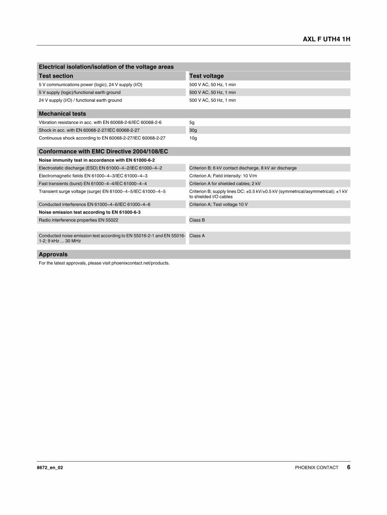
Electrical isolation/isolation of the voltage areas
Test section Test voltage
5 V communications power (logic), 24 V supply (I/O) 500 V AC, 50 Hz, 1 min
5 V supply (logic)/functional earth ground 500 V AC, 50 Hz, 1 min
24 V supply (I/O) / functional earth ground 500 V AC, 50 Hz, 1 min
Mechanical tests
Vibration resistance in acc. with EN 60068-2-6/IEC 60068-2-6 5g
Shock in acc. with EN 60068-2-27/IEC 60068-2-27 30g
Continuous shock according to EN 60068-2-27/IEC 60068-2-27 10g
Conformance with EMC Directive 2004/108/EC
Noise immunity test in accordance with EN 61000-6-2
Electrostatic discharge (ESD) EN 61000-4-2/IEC 61000-4-2 Criterion B; 6 kV contact discharge, 8 kV air discharge
Electromagnetic fields EN 61000-4-3/IEC 61000-4-3 Criterion A; Field intensity: 10 V/m
Fast transients (burst) EN 61000-4-4/IEC 61000-4-4 Criterion A for shielded cables; 2 kV
Transient surge voltage (surge) EN 61000-4-5/IEC 61000-4-5 Criterion B; supply lines DC: ±0.5 kV/±0.5 kV (symmetrical/asymmetrical); ±1 kV
to shielded I/O cables
Conducted interference EN 61000-4-6/IEC 61000-4-6 Criterion A; Test voltage 10 V
Noise emission test according to EN 61000-6-3
Radio interference properties EN 55022 Class B
Conducted noise emission test according to EN 55016-2-1 and EN 55016-
1-2; 9 kHz ... 30 MHz
Class A
Approvals
For the latest approvals, please visit phoenixcontact.net/products.
AXL F UTH4 1H
8672_en_02 PHOENIX CONTACT 7
5 Additional technical data
5.1 Maximum permissible cable lengths
TC inputs: select the appropriate TC equalizing conductors
for TC sensors (according to DIN EN 60584-3,
IEC 60584-3, and DIN 43722).
Other inputs: the values are valid when reference cable type
LiYCY (TP) 2 x 2 x 0.5 mm² is used in accordance with the
Axioline F installation instructions.
The maximum cable length specification is valid from the
sensor to the connection terminal block and includes the
maximum specified tolerances.
Observe the cable resistance values when operating the ex-
ternalPt 100 cold junction. Long cables and/or small cable
cross sections increase measuring tolerances.
The measuring tolerances of all channels will only be ob-
served if the permissible cable types are used.
Using the Axioline shield connection set
(AXL SHIELD SET), connect the braided shield of long sen-
sor cables at one end to the functional earth ground potential
upstream of the AXL F UTH4 1H module.
5.2 Measuring ranges of the TC inputs
Connecting cable and maximum cable length specifications
Maximum per-
missible cable
length
Sensor type Connection
method
Sensor cable Cable type
10 m TC inputs channel 1 ... 4 2-wire Unshielded, twisted TC sensor cable or equalizing conductor (ac-
cording to DIN EN 60584-3, IEC 60584-3,
DIN 43722)
250 m TC inputs channel 1 ... 4 2-wire Shielded, twisted TC sensor cable or equalizing conductor (ac-
cording to DIN EN 60584-3, IEC 60584-3,
DIN 43722)
10 m Inputs channel 1 ... 4,
-100 mV ... +100 mV
2-wire Unshielded, twisted Reference cable type LiYY (TP) 2 x 2 x 0.5 mm²
250 m Inputs channel 1 ... 4,
-100 mV ... +100 mV
2-wire Shielded, twisted Reference cable type LiYCY (TP) 2 x 2 x 0.5 mm²
2 m Pt 100 external cold junction sen-
sor
2-wire Unshielded, twisted Reference cable type LiYY (TP) 2 x 2 x 0.5 mm²
10 m Pt 100 external cold junction sen-
sor
2-wire Shielded, twisted Reference cable type LiYCY (TP) 2 x 2 x 0.5 mm²
5 m -5 V ... +5 V input 2-wire Shielded, twisted Reference cable type LiYCY (TP) 2 x 2 x 0.5 mm²
No. Input Sensor
type
Standard Measuring range Average basic
value for sensitivity
Voltage level at
measuring range
final value
Lower
limit
Upper
limit
1 Thermocouples B DIN EN 60584 +50 °C +1820 °C 6 µV/K 13.820 mV
2 E DIN EN 60584 -270 °C +1000 °C 65 µV/K 76.373 mV
3 J DIN EN 60584 -210 °C +1200 °C 54 µV/K 69.553 mV
4 K DIN EN 60584 -270 °C +1372 °C 42 µV/K 54.886 mV
5 N DIN EN 60584 -270 °C +1300 °C 27 µV/K 47.513 mV
6 R DIN EN 60584 -50°C +1768 °C 10 µV/K 21.101 mV
7 S DIN EN 60584 -50°C +1768 °C 10 µV/K 18.693 mV
8 T DIN EN 60584 -270 °C +400 °C 40 µV/K 20.872 mV
9 C -18 °C +2316 °C 15 µV/K 37.07 mV
10 W -18 °C +2316 °C 12 µV/K 38.56 mV
11 HK -200 °C +800 °C 69 µV/K 66.42 mV
12 L DIN 43710 -200 °C +900 °C 54 µV/K 53.14 mV
13 U DIN 43710 -200 °C +600 °C 40 µV/K 34.31 mV
AXL F UTH4 1H
8672_en_02 PHOENIX CONTACT 8
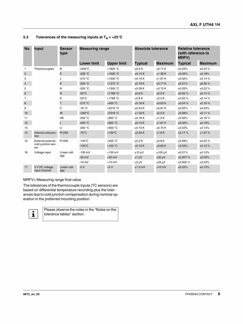
5.3 Tolerances of the measuring inputs at TA = +25°C
MRFV= Measuring range final value
The tolerances of the thermocouple inputs (TC sensors) are
based on differential temperature recording plus the toler-
ances due to cold junction compensation during nominal op-
eration in the preferred mounting position.
No. Input Sensor
type
Measuring range Absolute tolerance Relative tolerance
(with reference to
MRFV)
Lower limit Upper limit Typical Maximum Typical Maximum
1 Thermocouples B +500°C +1820 °C ±0.5 K ±4.17 K ±0.03% ±0.23 %
2 E -226 °C +1000 °C ±0.15 K ±1.38 K ±0.02% ±0.19%
3 J -210 °C +1200 °C ±0.19 K ±1.67 K ±0.02% ±0.14 %
4 K -200 °C +1372 °C ±0.19 K ±0.71 K ±0.01% ±0.05 %
5 N -200 °C +1300 °C ±0.39 K ±3.15 K ±0.03% ±0.23 %
6 R -50°C +1768 °C ±0.8 K ±2.5 K ±0.05 % ±0.14 %
7 S -50°C +1768 °C ±0.8 K ±2.5 K ±0.05 % ±0.14 %
8 T -270 °C +400 °C ±0.18 K ±0.63 K ±0.04 % ±0.16 %
9 C -18 °C +2316 °C ±0.53 K ±0.81 K ±0.02% ±0.03%
10 W +250°C +2316 °C ±1.33 K ±2.5 K ±0.06% ±0.11 %
11 HK -200 °C +800 °C ±0.16 K ±1.3 K ±0.02% ±0.16 %
12 L -200 °C +900 °C ±0.15 K ±1.67 K ±0.02% ±0.19%
13 U -200 °C +600 °C ±0.15 K ±0.75 K ±0.03% ±0.13%
14 Internal cold junc-
tion
Pt DIN -70°C +150°C ±0.25 K ±1.6 K ±0.17 % ±1.07 %
15 External external
cold junction sen-
sor
Pt DIN -100°C +400 °C ±0.3 K ±0.8 K ±0.08% ±0.20 %
-100°C +100 °C ±0.10 K ±0.60 K ±0.03% ±0.15 %
16 Voltage input Linear volt-
age
-100 mV +100 mV ±10 µV ±100 µV ±0.01% ±0.10%
-30 mV +30 mV ±7 µV ±30 µV ±0.007 % ±0.03%
-10 mV +10 mV ±5 µV ±25 µV ±0.005 % ±0.03%
17 5 V DC voltage
input channel
Linear volt-
age
-5 V +5 V ±1.5 mV ±10 mV ±0.03% ±0.10%
Please observe the notes in the "Notes on the
tolerance tables" section.
AXL F UTH4 1H
8672_en_02 PHOENIX CONTACT 9
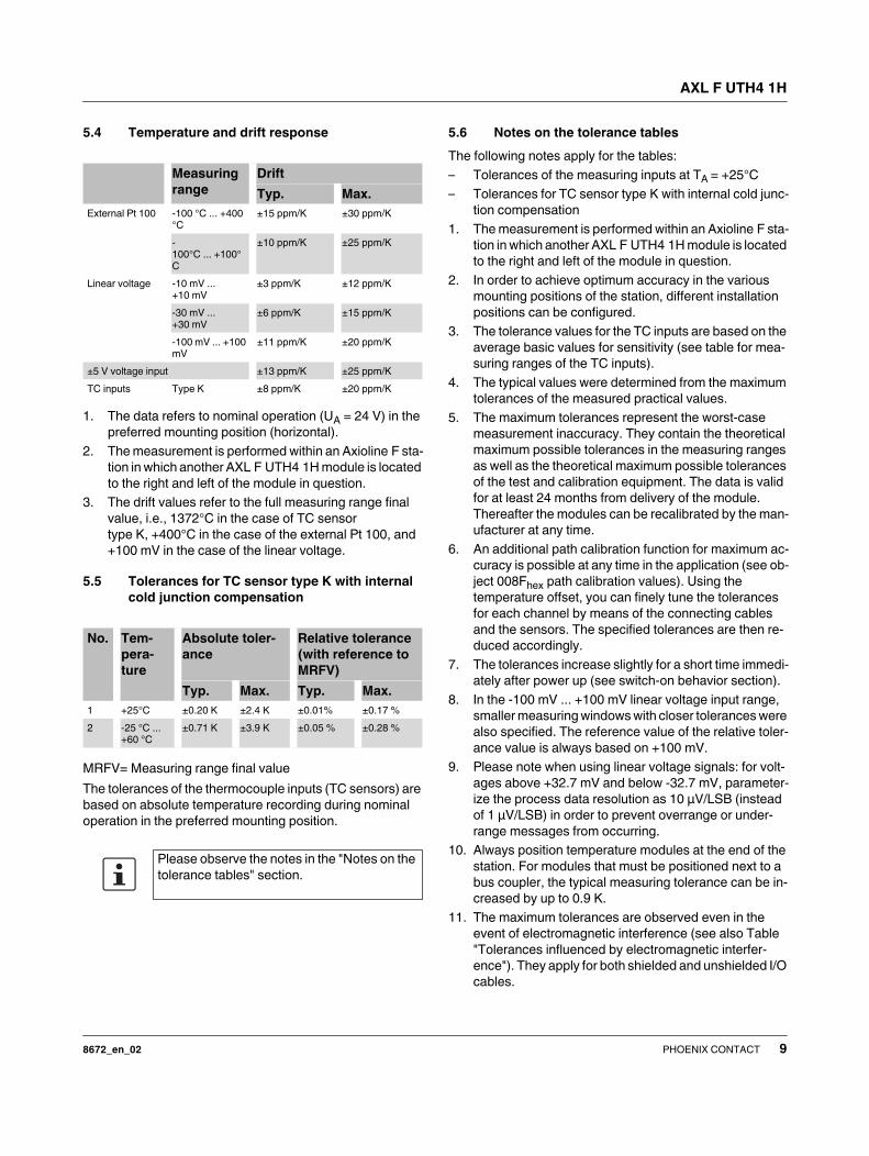
5.4 Temperature and drift response
1. The data refers to nominal operation (UA = 24 V) in the
preferred mounting position (horizontal).
2. The measurement is performed within an Axioline F sta-
tion in which another AXL F UTH4 1H module is located
to the right and left of the module in question.
3. The drift values refer to the full measuring range final
value, i.e., 1372°C in the case of TC sensor
type K, +400°C in the case of the external Pt 100, and
+100 mV in the case of the linear voltage.
5.5 Tolerances for TC sensor type K with internal
cold junction compensation
MRFV= Measuring range final value
The tolerances of the thermocouple inputs (TC sensors) are
based on absolute temperature recording during nominal
operation in the preferred mounting position.
5.6 Notes on the tolerance tables
The following notes apply for the tables:
– Tolerances of the measuring inputs at TA = +25°C
– Tolerances for TC sensor type K with internal cold junc-
tion compensation
1. The measurement is performed within an Axioline F sta-
tion in which another AXL F UTH4 1H module is located
to the right and left of the module in question.
2. In order to achieve optimum accuracy in the various
mounting positions of the station, different installation
positions can be configured.
3. The tolerance values for the TC inputs are based on the
average basic values for sensitivity (see table for mea-
suring ranges of the TC inputs).
4. The typical values were determined from the maximum
tolerances of the measured practical values.
5. The maximum tolerances represent the worst-case
measurement inaccuracy. They contain the theoretical
maximum possible tolerances in the measuring ranges
as well as the theoretical maximum possible tolerances
of the test and calibration equipment. The data is valid
for at least 24 months from delivery of the module.
Thereafter the modules can be recalibrated by the man-
ufacturer at any time.
6. An additional path calibration function for maximum ac-
curacy is possible at any time in the application (see ob-
ject 008Fhex path calibration values). Using the
temperature offset, you can finely tune the tolerances
for each channel by means of the connecting cables
and the sensors. The specified tolerances are then re-
duced accordingly.
7. The tolerances increase slightly for a short time immedi-
ately after power up (see switch-on behavior section).
8. In the -100 mV ... +100 mV linear voltage input range,
smaller measuring windows with closer tolerances were
also specified. The reference value of the relative toler-
ance value is always based on +100 mV.
9. Please note when using linear voltage signals: for volt-
ages above +32.7 mV and below -32.7 mV, parameter-
ize the process data resolution as 10 µV/LSB (instead
of 1 µV/LSB) in order to prevent overrange or under-
range messages from occurring.
10. Always position temperature modules at the end of the
station. For modules that must be positioned next to a
bus coupler, the typical measuring tolerance can be in-
creased by up to 0.9 K.
11. The maximum tolerances are observed even in the
event of electromagnetic interference (see also Table
"Tolerances influenced by electromagnetic interfer-
ence"). They apply for both shielded and unshielded I/O
cables.
Measuring
range
Drift
Typ. Max.
External Pt 100 -100 °C ... +400
°C
±15 ppm/K ±30 ppm/K
-
100°C ... +100°
C
±10 ppm/K ±25 ppm/K
Linear voltage -10 mV ...
+10 mV
±3 ppm/K ±12 ppm/K
-30 mV ...
+30 mV
±6 ppm/K ±15 ppm/K
-100 mV ... +100
mV
±11 ppm/K ±20 ppm/K
±5 V voltage input ±13 ppm/K ±25 ppm/K
TC inputs Type K ±8 ppm/K ±20 ppm/K
No. Tem-
pera-
ture
Absolute toler-
ance
Relative tolerance
(with reference to
MRFV)
Typ. Max. Typ. Max.
1 +25°C ±0.20 K ±2.4 K ±0.01% ±0.17 %
2 -25 °C ...
+60 °C
±0.71 K ±3.9 K ±0.05 % ±0.28 %
Please observe the notes in the "Notes on the
tolerance tables" section.
AXL F UTH4 1H
8672_en_02 PHOENIX CONTACT 10
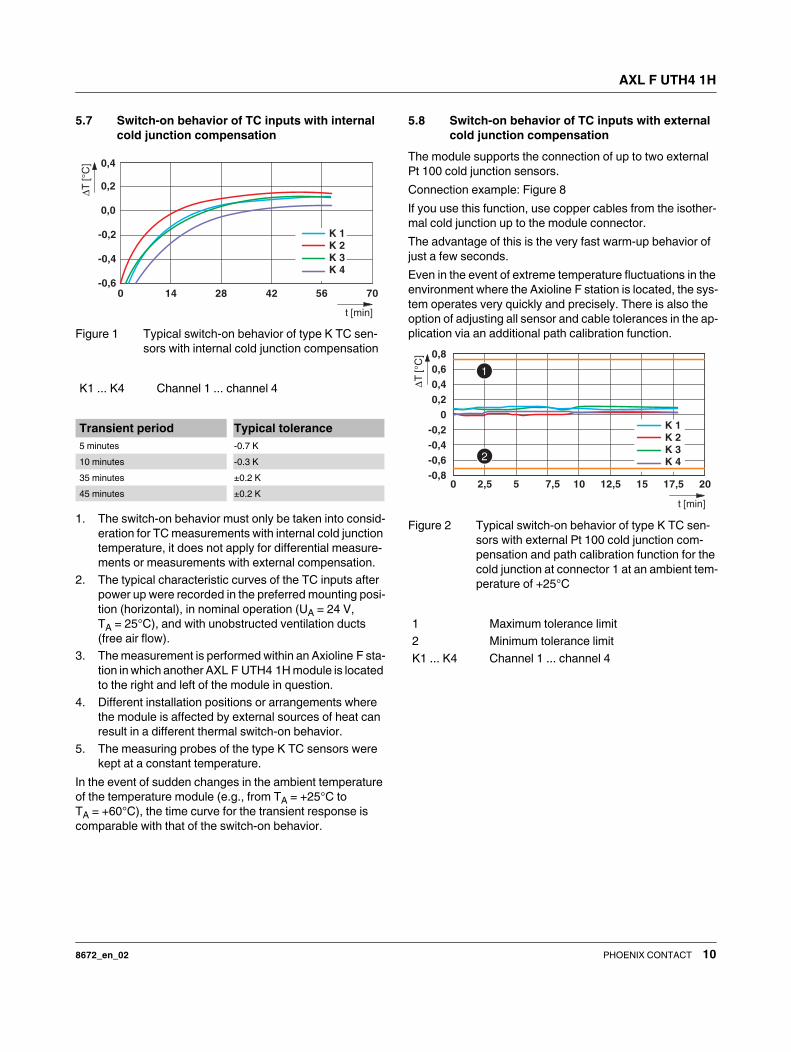
5.7 Switch-on behavior of TC inputs with internal
cold junction compensation
Figure 1 Typical switch-on behavior of type K TC sen-
sors with internal cold junction compensation
1. The switch-on behavior must only be taken into consid-
eration for TC measurements with internal cold junction
temperature, it does not apply for differential measure-
ments or measurements with external compensation.
2. The typical characteristic curves of the TC inputs after
power up were recorded in the preferred mounting posi-
tion (horizontal), in nominal operation (UA = 24 V,
TA = 25°C), and with unobstructed ventilation ducts
(free air flow).
3. The measurement is performed within an Axioline F sta-
tion in which another AXL F UTH4 1H module is located
to the right and left of the module in question.
4. Different installation positions or arrangements where
the module is affected by external sources of heat can
result in a different thermal switch-on behavior.
5. The measuring probes of the type K TC sensors were
kept at a constant temperature.
In the event of sudden changes in the ambient temperature
of the temperature module (e.g., from TA = +25°C to
TA = +60°C), the time curve for the transient response is
comparable with that of the switch-on behavior.
5.8 Switch-on behavior of TC inputs with external
cold junction compensation
The module supports the connection of up to two external
Pt 100 cold junction sensors.
Connection example: Figure 8
If you use this function, use copper cables from the isother-
mal cold junction up to the module connector.
The advantage of this is the very fast warm-up behavior of
just a few seconds.
Even in the event of extreme temperature fluctuations in the
environment where the Axioline F station is located, the sys-
tem operates very quickly and precisely. There is also the
option of adjusting all sensor and cable tolerances in the ap-
plication via an additional path calibration function.
Figure 2 Typical switch-on behavior of type K TC sen-
sors with external Pt 100 cold junction com-
pensation and path calibration function for the
cold junction at connector 1 at an ambient tem-
perature of +25°C
K1 ... K4 Channel 1 ... channel 4
Transient period Typical tolerance
5 minutes -0.7 K
10 minutes -0.3 K
35 minutes ±0.2 K
45 minutes ±0.2 K
K 1K 2K 3K 4
T
[°C
]
t [min]
-0,6
-0,4
-0,2
0,0
0,2
0,4
0 14 28 42 56 70
1 Maximum tolerance limit
2 Minimum tolerance limit
K1 ... K4 Channel 1 ... channel 4
-0,8
-0,6
-0,4
-0,2
0
0,2
0,4
0,6
0,8
K 1K 2K 3K 4
0 2,5 5 7,5 10 12,5 15 17,5 20
T
[°C
]
t [min]
AXL F UTH4 1H
8672_en_02 PHOENIX CONTACT 11
5.9 Technical data for cold junctions
Internal cold junctions
Simple cold junction compensation can be implemented for
the thermocouple inputs using the internal cold junctions.
To read the temperature of each internal cold junction for TC
channels, parameterize the sensor type as "Cold Junction".
For the accuracy, please refer to the tables of the tolerance
values.
Compensation of the mounting position of the internal
cold junction
In order that maximum accuracy is also achieved when in-
stalled in various different mounting positions, it is possible
to compensate the mounting position of the internal cold
junction.
Parameterize this compensation using the ParaTable ob-
ject, data format, mounting position.
Tolerances of the internal cold junction
* Thermally steady system without external heat influence
1. The data refers to nominal operation (UA = 24 V) in the
preferred mounting position (horizontal).
2. The measurement is performed within an Axioline F sta-
tion in which another AXL F UTH4 1H module is located
to the right and left of the module in question.
ExternalPt 100 cold junctions
When using external isothermal blocks or distributed termi-
nal boxes, an external cold junction is recommended. The
advantage of this is an improved switch-on behavior and the
very fast thermal transient period in the event of sudden
changes to the ambient temperature of the measuring sta-
tion.
You can connect up to two Pt 100 sensors to the
AXL F UTH4 1H module.
You can also use the inputs for the external cold junction
sensors as sensor inputs for any applications with Pt 100
and connection with 2-wire technology. To do so, parame-
terize the sensor type as “Cold junction” and the cold junc-
tion type as “External Pt 100” on the corresponding connec-
tor.
Tolerances of the external Pt100 cold junction inputs
The data contains the offset error, gain error, and linearity
error in its respective setting.
The data is valid for nominal operation (preferred mounting
position, UA = 24 V).
The documented typical tolerances were determined for ref-
erence cable type LiYCY (TP) 2 x 2 x 0.5 mm² with a con-
nection length < 1 m.
The drift data and the tolerances specified as a percentage
refer to the measuring range final value of +400°C.
The typical data has been determined in an example Axi-
oline F station.
Typical tolerance values are measured application values
that are based on the maximum variance of all test objects.
The maximum tolerance values represent the worst-case
measurement inaccuracy. They contain the theoretical max-
imum possible tolerances in the corresponding measuring
ranges as well as the theoretical maximum possible toler-
ances of the calibration and test equipment. The data is valid
for at least 24 months from delivery of the module. Thereaf-
Internal cold junction
Connection method 2-wire connection
Sensor type Pt 100 DIN
R0 (sensor resistance at TA = 0°C) 100 Ω
Measuring range -55°C ... +125°C
Resolution (process data) 0.1 K/LSB
Resolution (floating point object) < 0.001 K
Filter time 120 ms
No. Tolerance struc-
ture
Temper-
ature
Tolerances
Typ. Max.
1 Cold junction tempera-
ture drift
-25 °C ...
+60 °C
10 ppm/K 25 ppm/K
2 Total tolerance of the in-
ternal cold junction
+25°C ±0.15 K ±1.76 K
3 Total tolerance of the in-
ternal cold junction
-25 °C ...
+60 °C
±0.85 K ±2.4 K
ExternalPt 100 cold junctions
Connection method 2-wire connection
Sensor type Pt 100 DIN
R0 (sensor resistance at TA = 0°C) 100 Ω
Measuring range -100 °C ... +400 °C
Resolution (process data) 0.1 K/LSB
Resolution (floating point object) < 0.001 K
Filter time 120 ms
No. Ambient
temperature
Tolerances
Typ. Max.
1 Tolerances +25°C ±0.3 K ±0.8 K
2 Drift -25 °C ... +60 °C ±10 ppm/K ±25 ppm/K
AXL F UTH4 1H
8672_en_02 PHOENIX CONTACT 12
ter the modules can be recalibrated by the manufacturer at
any time.
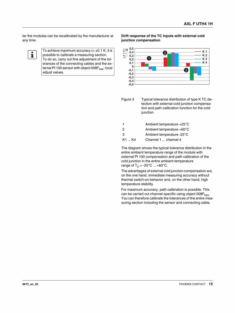
Drift response of the TC inputs with external cold
junction compensation
Figure 3 Typical tolerance distribution of type K TC de-
tection with external cold junction compensa-
tion and path calibration function for the cold
junction
The diagram shows the typical tolerance distribution in the
entire ambient temperature range of the module with
external Pt 100 compensation and path calibration of the
cold junction in the entire ambient temperature
range of TU = -25°C ... +60°C.
The advantages of external cold junction compensation are,
on the one hand, immediate measuring accuracy without
thermal switch-on behavior and, on the other hand, high
temperature stability.
For maximum accuracy, path calibration is possible. This
can be carried out channel-specific using object 008Fhex.
You can therefore calibrate the tolerances of the entire mea-
suring section including the sensor and connecting cable.
To achieve maximum accuracy (< ±0.1 K, it is
possible to calibrate a measuring section.
To do so, carry out fine adjustment of the tol-
erances of the connecting cables and the ex-
ternal Pt 100 sensor with object 008Fhex: local
adjust values.
1 Ambient temperature +25°C
2 Ambient temperature +60°C
3 Ambient temperature -25°C
K1 ... K4 Channel 1 ... channel 4
T
[°C
]
K 1K 2K 3K 4
-0,5-0,4-0,3-0,2-0,1
00,10,20,30,40,5
AXL F UTH4 1H
8672_en_02 PHOENIX CONTACT 13
5.10 Technical data for the ±5 V DC voltage input
This input is used to acquire additional voltage signals.
Connect a signal converter to the input. This can be used to
acquire any AC or DC currents which are converted by the
converter into an electrically isolated ±5 V signal. This ±5 V
signal is processed by the module.
Connection example: Figure 13
Tolerances of the voltage input
Typical tolerance values are measured application values
that are based on the maximum variance of all test objects.
The maximum tolerance values represent the worst-case
measurement inaccuracy. They contain the theoretical max-
imum possible tolerances in the corresponding measuring
ranges as well as the theoretical maximum possible toler-
ances of the calibration and test equipment. The data is valid
for at least 24 months from delivery of the module. Thereaf-
ter the modules can be recalibrated by the manufacturer at
any time.
Use an isolating amplifier to decouple from the field the sen-
sor signals which go to the sensor input. The MCR range
from Phoenix Contact offers various solutions (see also con-
nection example "Universal AC and DC current acquisition
by means of combination with a current transducer").
5.11 Cycle times
±5 V voltage input
Connection method 2-wire connection
Measuring range -5 V ... +5 V
Format IB IL
Resolution 16-bit
Quantization 166.7 µV/LSB
Filter time 120 ms
Input resistance typ. 5 MΩ
No. Tem-
pera-
ture
Absolute Relative
Typ. Max. Typ. Max.
1 Toler-
ance
+25°C ±1 mV ±10 mV ±0.02% ±0.20 %
2 Toler-
ance
-25 °C ...
+60 °C
±2.3 mV ±15 mV ±0.05 % ±0.30%
3 Drift -25 °C ...
+60 °C
±8 ppm/K ±20 ppm/K
Filter time Channel conversion time for TC opera-
tion with internal compensation
120 ms 120 ms
100 ms 100 ms
60 ms 60 ms
40 ms 40 ms
Filter time Typical scan repeat time for all four
measuring channels
TC operation with internal cold junc-
tion compensation
120 ms 962 ms
100 ms 880 ms
60 ms 720 ms
40 ms 640 ms
Filter time Typical scan repeat time for a measur-
ing channel
TC operation with internal cold junc-
tion compensation; channels 2 ... 4
deactivated
120 ms 600 ms
100 ms 580 ms
60 ms 540 ms
40 ms 520 ms
AXL F UTH4 1H
8672_en_02 PHOENIX CONTACT 14
5.12 Tolerances influenced by electromagnetic interference
The values determined apply for both shielded and un-
shielded twisted sensor cables. The maximum cable
lengths should be taken into consideration.
For all tested electromagnetic interferences (see table), the
measured values were within the maximum tolerances.
The values were determined under nominal conditions with
the following sensor settings and sensor circuits:
– Thermocouple type K (NiCr-Ni) with internal cold junc-
tion compensation, filter = 120 ms
– External RTD sensor type Pt 100 as sensor input, fil-
ter = 120 ms
– -100 mV ... +100 mV linear voltage signals, 1 µV/LSB
resolution, filter = 120 ms
Type of electromag-
netic interference
Standard Level Additional toler-
ances of measuring
range final value
Criterion
Electromagnetic fields EN 61000-4-3/IEC 61000-4-3 10 V/m None A
Fast transients (burst) EN 61000-4-4/IEC 61000-4-4 1.1 kV None A
Conducted interference EN 61000-4-6/IEC 61000-4-6 150 kHz ... 80 MHz, 10 V, 80% (1 kHz) None A
No additional tolerances occur due to the in-
fluence of high-frequency interference
caused by wireless transmission systems in
the near vicinity.
The specifications refer to nominal operation.
The modules are directly exposed to interfer-
ence without the use of additional shielding
measures (e.g., steel cabinet).
AXL F UTH4 1H
8672_en_02 PHOENIX CONTACT 15
6 Internal circuit diagram
Figure 4 Internal wiring of the terminal points
Key:
D
UA
E1
E2
2x
UTH 1...4U
24 VA
UBus
Local busC
#
U
Supervisor
FE
Supervisor
+5V DC
CJ
Pt1001..2
Local bus Axioline F local bus
(hereinafter referred to as local bus)
Microcontroller
Optocoupler
Power supply unit with electrical isola-
tion
Analog/digital converter
Low pass filter
Hardware monitoring
Constant current source
Difference amplifier
Reference ground for communications
power
Noiseless ground
Electrically isolated areas
Cold junction (CJ)
µC
Supervisor
CJ
AXL F UTH4 1H
8672_en_02 PHOENIX CONTACT 16
7 Terminal point assignment
Figure 5 Terminal point assignment
8 Connection examples
8.1 Absolute temperature measurement with
internal cold junction compensation
Figure 6 Connection example: absolute temperature
measurement
A thermocouple sensor is connected to each of the four
channels.
For example, sensor type J (TC1) and sensor type K (TC2)
are used at channels 1 and 2.
The measuring temperature of TC1 and TC2 is automati-
cally determined by the module by means of internal cold
junction compensation.
Parameterize the cold junction type as "Internal" (preset by
default).
This application is the simple standard application for tem-
perature recording with thermocouples.
Termi-
nal
point
Color Assignment
Supply voltage input
a1, a2 Red 24 V DC
(UA)
Analog module supply
(internally jumpered)
b1, b2 Blue GND Reference potential of
the supply voltage (inter-
nally jumpered)
Analog inputs
00, 02 Orange CJ1+,
CJ2+
External external cold
junction sensor (+)
01 Orange - Not used
10, 12 Orange CJ1-,
CJ2-
External external cold
junction sensor (-)
11 Orange - Not used
03 Orange U+ Voltage input 5 V (+)
13 Orange U- Voltage input 5 V (-)
20 ... 23 Orange TC1+ ...
TC4+
Thermocouple (+)
30 ... 33 Orange TC1- ...
TC4-
Thermocouple (-)
0300131023203330
a1
a2
b1
b2
00
10
20
30
01
11
21
31
02
12
22
32
03
13
23
33
a1a2b1b2
00
10
20
30
01
11
21
31
02
12
22
32
03
13
23
33
a1
a2
b1
b2
AXL F UTH4 1H
8672_en_02 PHOENIX CONTACT 17
8.2 Differential temperature measurement
Precise differential temperature recording is a special appli-
cation, e.g., in process engineering and process technol-
ogy. You can determine the exact differential temperature,
e.g., between an inlet and return temperature, by connect-
ing two thermocouples in series to one channel of the mod-
ule.
Parameterize the cold junction type as "Disabled".
The pure differential temperature between the measuring
points will therefore be recorded.
Figure 7 Differential temperature measurement
By linking the two thermocouples (here type K, NiCr-Ni), the
temperature difference between both thermoelectric volt-
ages is determined.
Where:
The advantage of this application is the high degree of pre-
cision without a waiting time to warm up.
8.3 Thermocouple detection with external cold
junction compensation
For applications with a high degree of precision, the module
offers the option of compensation using an external cold
junction.
Each connector has a connection for an external Pt 100 cold
junction sensor.
External cold junction compensation is implemented for
each channel.
Proceed as follows:
• Route the sensor cables of the thermocouple to an iso-
thermal block.
• For each channel, wire a copper (Cu) connecting cable
from the isothermal block to the input terminals of the
module.
• Connect the external Pt 100 cold junction sensor to the
isothermal block using a Pt 100 input of connector 1 or
2 (connector 1 in the example).
• Parameterize the cold junction type of the desired input
channel as “External, Pt 100, connector x” (x = 1 or 2;
channel 1 in the example)
The advantage of this application is the improved warm-up
behavior in the first few minutes after the module is switched
on.
Figure 8 Thermocouple detection with external cold
junction compensation at channel 1
TD = T1 - T2
UM = UT1 - UT2
TD Temperature difference
T1/T2 Temperature at sensor 1/2
UM Differential thermoelectric voltage
UT1/UT2 Thermoelectric voltage sensor 1/2
00
10
20
30
01
11
21
31
02
12
22
32
03
13
23
33
a1
a2
b1
b2
T1
T2
UT1
UT2
+
-
-
+
NICr
NICr
NI
NI
As an input is available at each connector for
an external Pt 100 cold junction sensor, you
can operate up to two external cold junction
sensors. If you have connected two cold junc-
tion sensors, you can then select any cold
junction type, i.e., you can use the Pt 100 of
connector 1 or 2.
A Pt 100 external cold junction sensor
B Isothermal block
00
10
20
30
01
11
21
31
02
12
22
32
03
13
23
33
a1
a2
b1
b2
T1
T2
T3
T4
+
+
+
+
-
-
-
-
Cu
Cu
Cu
Cu
Pt100
A
B
AXL F UTH4 1H
8672_en_02 PHOENIX CONTACT 18
8.4 Thermocouple detection with cold junction
temperature specification via process data
Another option for compensating the cold junction tempera-
ture externally is to specify the cold junction temperature via
process data.
In this way, the temperature of the external cold junction can
be recorded at the isothermal block via any system and used
for compensation.
Proceed as follows:
• Route the sensor cables of the thermocouple to an iso-
thermal block.
• For each channel, wire a copper (Cu) connecting cable
from the isothermal block to the input terminals of the
module.
• Write the cold junction temperature recorded externally
by the isothermal block to the first process data output
word of the module in your application (IB IL format).
• Parameterize the cold junction type of the desired input
channel as "Process data".
Figure 9 Thermocouple detection with cold junction
temperature specification via process data
8.5 Measurement of linear mV voltage signals
You can connect sensors to each channel which supply a
linear voltage in the mV range, e.g., pressure or Hall sen-
sors.
• Parameterize the corresponding channel as sensor
type “Linear voltage ±100 mV”.
Figure 10 Measurement of linear voltages ±100 mV
A cable break on the sensor cables is monitored and de-
tected.
The ±10 mV and ±30 mV ranges are more accurate than the
entire ±100 mV range and have therefore also been speci-
fied.
For mV sensors, cable lengths of up to 250 m are possible.
Please note the cable length specifications and suitable
sensor cable types.
For voltages above +32.7 mV and below -32.7 mV, parame-
terize the process data resolution as 10 µV/LSB (instead of
1 µV/LSB) in order to prevent overrange or underrange mes-
sages from occurring.
For each module, you can use a digital exter-
nal process data value for cold junction com-
pensation.
OUT1 = TCJ 0 0 0 0
TCJ Cold junction temperature
B Isothermal block
00
10
20
30
01
11
21
31
02
12
22
32
03
13
23
33
a1
a2
b1
b2
T1
T2
T3
T4
+
+
+
+
-
-
-
-
Cu
Cu
Cu
Cu
B
TCJ
00
10
20
30
01
11
21
31
02
12
22
32
03
13
23
33
a1
a2
b1
b2
100 mV+-
100 mV+-
100 mV+-
100 mV+-
AXL F UTH4 1H
8672_en_02 PHOENIX CONTACT 19
8.6 Pt 100 detection
You can also use the inputs for external Pt 100 cold junction
sensors as Pt 100 sensor inputs.
To do this, proceed as follows:
• Connect the Pt 100 sensor with 2-wire technology to
connector 1 or 2.
• Parameterize a desired channel as sensor type “Cold
junction (CJ)” and parameterize the cold junction type
as “External, Pt 100, connector x” (x = 1 or 2).
• Record the temperature value of the external Pt 100
sensor at the parameterized channel with a resolution of
0.1 K/LSB.
Figure 11 Pt 100 detection
8.7 Measurement of a ±5 V signal
A -5 V ... +5 V input is available for acquisition from a wide
range of signal sources.
Figure 12 Measurement of a linear voltage ±5 V DC
In this way, you can acquire isolated Pt 100 signals, for ex-
ample, from very remote areas (> 100 m) with a temperature
transducer (e.g., MCR-T-UI-E) in 4-wire technology and
read them in via the -5 V ... +5 V input. You can use this for
external cold junction compensation of very remote control
boxes, if copper TC sensor cables need to be used.
Make sure that the sensor cable is no more
than 10 m in length.
To achieve maximum accuracy (< ±0.1 K, it is
possible to calibrate a measuring section.
To do so, carry out fine adjustment of the tol-
erances of the connecting cables and the ex-
ternal Pt 100 sensor with object 008Fhex: local
adjust values.
00
10
20
30
01
11
21
31
02
12
22
32
03
13
23
33
a1
a2
b1
b2
Pt100
Pt100
Make sure that the shielded twisted sensor
cable is no more than 5 m in length at the ±5 V
input.
If longer cable lengths are required, connect
appropriate converters or signal conditioners
upstream.
The MCR range from Phoenix Contact offers
a comprehensive range of products for this.
00
10
20
30
01
11
21
31
02
12
22
32
03
13
23
33
a1
a2
b1
b2
5 V+-
AXL F UTH4 1H
8672_en_02 PHOENIX CONTACT 20
8.8 Universal AC and DC current acquisition in
combination with a current transducer
Any AC or DC currents with 300 V AC safe isolation accord-
ing to EN 50178, EN 61010, such as heating currents, can
be acquired via the ±5 V voltage input (terminal points 02
and 12) using a current transducer.
For signal conditioning, use the MCR-S-1-5-UI(-SW)-DCI
current transducer from Phoenix Contact, for example.
Figure 13 Measurement of an AC or DC current signal at
the -5 V voltage input ... +5 V DC in combina-
tion with a current transducer (heating current
acquisition)
9 Connection notes
Use encapsulated thermocouples.
Always connect the thermocouples using twisted pair equal-
izing conductors.
Use shielded twisted pair equalizing conductors for a cable
length from 10 m.
For mV sensors in environments prone to interference as
well as for sensor cables which are longer than 10 m. use
shielded twisted connecting cables (e.g., LiYCY (TP) 2 x 2 x
0.5 mm2).
For TC sensors, use the corresponding shielded TC con-
necting cable according to DIN EN 60584-3/ISO 60584-3.
For optimum shield connection directly before the module,
use the AXL SHIELD SET Axioline shield connection set
(see ordering data).
Please refer to the UM EN AXL SYS INST user manual for
information on how to install the set and connect the shield.
For installation in a control cabinet: connect the cable shield
to functional earth ground immediately after the cables enter
the control cabinet. Route the shield as far as the Axioline F
temperature module without interruption.
10 Configuration notes
Always position temperature modules at the end of the sta-
tion. For modules that must be positioned next to a bus cou-
pler, the typical measuring tolerance can be increased by up
to 0.9 K.
IIn AC/DC input current, 0 mA ... 200 mA up
to 0 A ... 11 A, 15 Hz ... 400 Hz
UOut -5 V DC ... +5 V DC output voltage
MCR-S-1-5-UI(-
SW)-DCI
Current transducer
Make sure that the shielded twisted sensor
cable is no more than 5 m in length from the
current transducer to the temperature mod-
ule.
If longer cable lengths are required, connect
appropriate converters or signal conditioners
upstream.
The MCR range from Phoenix Contact offers
a comprehensive range of products for this.
00
10
20
30
01
11
21
31
02
12
22
32
03
13
23
33
a1
a2
b1
b2
UOutIIn
Power24 V
I50 mA AC
MCR-S-1-5-UI(-SW)-DCI
AXL F UTH4 1H
8672_en_02 PHOENIX CONTACT 21
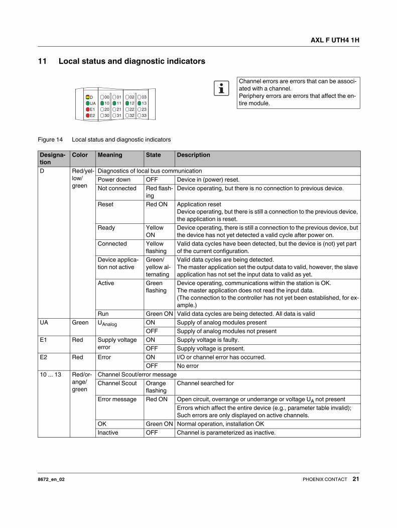
11 Local status and diagnostic indicators
Figure 14 Local status and diagnostic indicators
30
20
10
00
32
22
12
02
31
21
11
01
33
23
13
03D
UA
E1
E2
Channel errors are errors that can be associ-
ated with a channel.
Periphery errors are errors that affect the en-
tire module.
Designa-
tion
Color Meaning State Description
D Red/yel-
low/
green
Diagnostics of local bus communication
Power down OFF Device in (power) reset.
Not connected Red flash-
ing
Device operating, but there is no connection to previous device.
Reset Red ON Application reset
Device operating, but there is still a connection to the previous device,
the application is reset.
Ready Yellow
ON
Device operating, there is still a connection to the previous device, but
the device has not yet detected a valid cycle after power on.
Connected Yellow
flashing
Valid data cycles have been detected, but the device is (not) yet part
of the current configuration.
Device applica-
tion not active
Green/
yellow al-
ternating
Valid data cycles are being detected.
The master application set the output data to valid, however, the slave
application has not set the input data to valid as yet.
Active Green
flashing
Device operating, communications within the station is OK.
The master application does not read the input data.
(The connection to the controller has not yet been established, for ex-
ample.)
Run Green ON Valid data cycles are being detected. All data is valid
UA Green UAnalog ON Supply of analog modules present
OFF Supply of analog modules not present
E1 Red Supply voltage
error
ON Supply voltage is faulty.
OFF Supply voltage is present.
E2 Red Error ON I/O or channel error has occurred.
OFF No error
10 ... 13 Red/or-
ange/
green
Channel Scout/error message
Channel Scout Orange
flashing
Channel searched for
Error message Red ON Open circuit, overrange or underrange or voltage UA not present
Errors which affect the entire device (e.g., parameter table invalid);
Such errors are only displayed on active channels.
OK Green ON Normal operation, installation OK
Inactive OFF Channel is parameterized as inactive.
AXL F UTH4 1H
8672_en_02 PHOENIX CONTACT 22
Error code and status of the E1 and E2 LEDs
Error E1 LED E2 LED
No error OFF OFF
Underrange OFF ON
Overrange OFF ON
Open circuit OFF ON
Faulty supply voltage ON ON
Parameter table invalid OFF ON
Device error OFF ON
Flash format error OFF ON
AXL F UTH4 1H
8672_en_02 PHOENIX CONTACT 23
12 Process data
The module uses five words of IN process data and
five words of OUT process data.
12.1 Input words IN1 to IN5
The measured values of the TC channels are transmitted to
the controller board or the computer via process data input
words IN1 to IN5.
IN5 is used to transmit the measured value for the voltage in-
put.
The measured values are depicted in IB IL or S7-compatible
format. In both cases, the measured value is displayed in
16 bit format. The data type is Integer 16 from a technical
programming point of view.
In the IB IL format a diagnostic code is mapped to the input
data in the event of an error.
Note regarding code 8008hex:in the event of a cold junction
error, code 8008hex is indicated for the channel to which the
affected cold junction is assigned.
In order to determine the exact cause of the error, select the
"Cold junction" sensor type via the parameterization. The
detailed error message is then output for this channel
(8080hex, 8001hex or 8002hex).
12.2 Output words OUT1 to OUT5
13 Open circuit
13.1 Channels 1 to 4 (TC/linear voltage)
Channels 1 to 4 have open circuit detection.
As soon as an open circuit occurs, this is indicated in the
process data and in PDI object 0018hex.
In addition, the corresponding diagnostic LED for the chan-
nel lights up red.
13.2 Voltage input ±5 V
In the event of an error, the voltage input value goes to 0.
A diagnostic message is not generated, this error is not indi-
cated at the diagnostic LEDs either.
IN1: measured value channel 1
:
IN4: measured value channel 4
IN5: measured value voltage input
15 14 13 12 11 10 9 8 7 6 5 4 3 2 1 0
Analog value
Code (hex) Cause
8001 Measuring range exceeded (overrange)
8002 Open circuit
8004 Measured value invalid/no valid mea-
sured value available
8008 Cold junction defective
8010 Parameter table invalid
8020 Faulty supply voltage
8040 Device faulty
8080 Below measuring range (underrange)
OUT1: cold junction temperature specification
OUT2: -
:
OUT5: -
AXL F UTH4 1H
8672_en_02 PHOENIX CONTACT 24
14 Significant values in various formats
14.1 Significant values in IB IL format
14.2 Significant values in S7-compatible format
Input data Temperature sensors Linear voltage ±100 mV
Resolution 1°C or 1°F 0.1°C or 0.1°F 1 µV 10 µV
hex dec °C or °F °C or °F
8001 Overrange > Limit value > Limit value > 32.512 mV > 100 mV
03E8 1000 +1000.0 +100.0 +1 mV +10 mV
0001 1 +1.0 +0.1 +1 µV +10 µV
0000 0 0 0 0 µV 0 µV
FFFF -1 -1 -0.1 -1 µV -10 µV
FC18 -1000 -1000.0 -100.0 -1 mV -10 mV
8080 Underrange < Limit value < Limit value < -32.512 mV < -100 mV
Input data Temperature sensors Linear voltage ±100 mV
Resolution 1°C or 1°F 0.1°C or 0.1°F 1 µV 10 µV
hex dec °C or °F °C or °F
8000 Overrange > Limit value > Limit value > 32.512 mV > 100 mV
03E8 1000 +1000.0 +100.0 +1 mV +10 mV
0001 1 +1.0 +0.1 +1 µV +10 µV
0000 0 0 0 0 0
FFFF -1 -1 -0.1 -1 µV -10 µV
FC18 -1000 -1000.0 -100.0 -1 mV -10 mV
7FFF Underrange < Limit value < Limit value < -32.512 mV < -100 mV
AXL F UTH4 1H
8672_en_02 PHOENIX CONTACT 25
15 Parameter, diagnostics and
information (PDI)
Parameter and diagnostic data as well as other information
is transmitted via the PDI channel of the Axioline F station.
The standard and application objects stored in the module
are described in the following section.
The following applies to all tables below:
Please refer to the UM EN AXL F SYS INST for an explana-
tion of the object codes and data types.
Abbreviation Meaning
A Number of elements
L Length of the elements in bytes
R Read
W Write
Every visible string is terminated with a zero
terminator (00hex). The length of a visible
string element is therefore one byte larger
than the amount of user data.
For detailed information on PDI and the ob-
jects, please refer to the
UM EN AXL F SYS INST user manual.
AXL F UTH4 1H
8672_en_02 PHOENIX CONTACT 26
16 Standard objects
16.1 Objects for identification (device rating plate)
Index
(hex)
Object name Object
type
Data type A L Rights Meaning Contents
Manufacturer
0001 VendorName Var Visible String 1 16 R Vendor name Phoenix Contact
0002 VendorID Var Visible String 1 7 R Vendor ID 00A045
0003 VendorText Var Visible String 1 49 R Vendor text Components and
systems for indus-
trial automation
0012 VendorURL Var Visible String 1 30 R Vendor URL http://www.phoenix-
contact.com
Module - general
0004 DeviceFamily Var Visible String 1 14 R Device family I/O analog IN
0006 ProductFamily Var Visible String 1 33 R Product family Axioline - High
speed I/O system
000E CommProfile Var Visible String 1 4 R Communication pro-
file
633
000F DeviceProfile Var Visible String 1 5 R Device profile 0010
0011 ProfileVersion Record Visible String 2 11; 20 R Profile version 2011-12-07;
Basic Profile V2.0
003A VersionCount Array Unsigned 16 4 4 * 2 R Version counter e. g., 0007 0001
0001 0001hex
Module - special
0005 Capabilities Array Visible String 1 8 R Capabilities Nothing
0007 ProductName Var Visible String 1 17 R Product name AXL F UTH4 1H
0008 SerialNo Var Visible String 1 11 R Serial number xxxxxxxxxx (e. g.,
1234512345)
0009 ProductText Var Visible String 1 24 R Product text 4 analog input chan-
nels
000A OrderNumber Var Visible String 1 8 R Order No. 2688598
000B HardwareVersion Record Visible String 2 11; 3 R Hardware version e. g., 2010-06-21; 01
000C FirmwareVersion Record Visible String 2 11; 6 R Firmware version e. g., 2010-06-21;
V1.10
000D PChVersion Record Visible String 2 11; 6 R Parameter channel
version
2010-01-08; V1.00
0037 DeviceType Var Octet string 1 8 R Module identification 00 20 00 08 00 00 00
A8hex
Use of the device
0014 Location Var Visible String 1 59 R/W Location Can be filled out by
the user.
0015 EquipmentIdent Var Visible String 1 59 R/W Equipment identifier Can be filled out by
the user.
0016 ApplDeviceAddr Var Unsigned 16 1 2 R/W Application device
address
Can be filled out by
the user.
AXL F UTH4 1H
8672_en_02 PHOENIX CONTACT 27
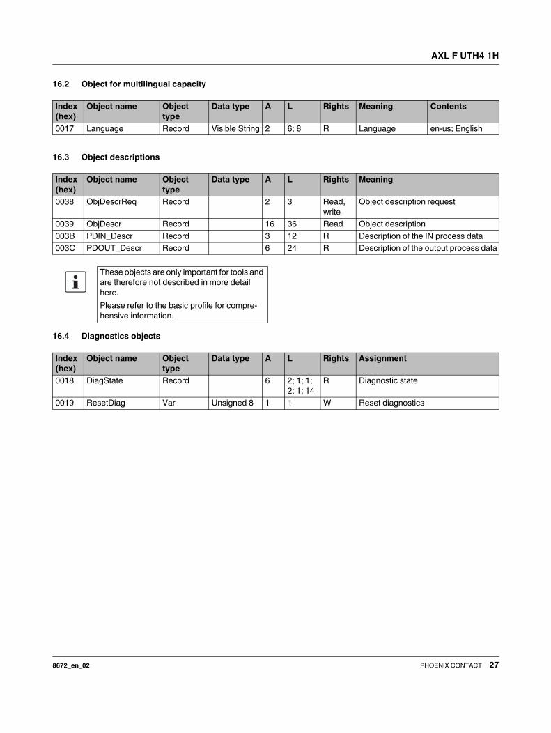
16.2 Object for multilingual capacity
16.3 Object descriptions
16.4 Diagnostics objects
Index
(hex)
Object name Object
type
Data type A L Rights Meaning Contents
0017 Language Record Visible String 2 6; 8 R Language en-us; English
Index
(hex)
Object name Object
type
Data type A L Rights Meaning
0038 ObjDescrReq Record 2 3 Read,
write
Object description request
0039 ObjDescr Record 16 36 Read Object description
003B PDIN_Descr Record 3 12 R Description of the IN process data
003C PDOUT_Descr Record 6 24 R Description of the output process data
These objects are only important for tools and
are therefore not described in more detail
here.
Please refer to the basic profile for compre-
hensive information.
Index
(hex)
Object name Object
type
Data type A L Rights Assignment
0018 DiagState Record 6 2; 1; 1;
2; 1; 14
R Diagnostic state
0019 ResetDiag Var Unsigned 8 1 1 W Reset diagnostics
AXL F UTH4 1H
8672_en_02 PHOENIX CONTACT 28
Diagnostics state (0018hex: DiagState)
This object is used for a structured message of an error.
0018hex: DiagState (Read)
Subindex Data type Length in
bytes
Meaning Contents
0 Record 21 Diagnostic state Complete diagnostics information
1 Unsigned 16 2 Error number 0 ... 65535dez
2 Unsigned 8 1 Priority 00hex No error
01hex Error
02hex Warning
81hex Error removed
82hex Warning eliminated
3 Unsigned 8 1 Channel/group/module 00hex No error
01hex Channel 1
: :
04hex Channel 4
05hex ±5 V voltage input
FFhex entire device
4 Unsigned 16 2 Error code See table below
5 Unsigned 8 1 More follows 00hex
6 Visible String 14 Text (14 characters) See table below
The message with the priority 81hex or 82hex is
a one-time internal message to the bus cou-
pler that is implemented onto the error mech-
anisms of the higher-level system by the bus
coupler.
AXL F UTH4 1H
8672_en_02 PHOENIX CONTACT 29
Error and status of the local status and diagnostics indicators
Reset diagnostic mesages (0019hex: ResetDiag)
You can delete the diagnostics memory and acknowledge the diagnostic messages with this object.
Subindex 2 3 4 6
Error Pri-
ority
Chan-
nel/
group/
module
Error code Text Process
data
LED
hex hex hex dec D UA E1 E2 10 ... 13
No error 00 00 0000 0 Status OK xxxx Green ON ON OFF OFF X
Cold junction in-
valid
01 01 ... 04 5120 20768 Cold junc-
tion (CJ)
8008 Green ON ON OFF ON Red ON
Faulty supply volt-
age
01 FF 5160 20832 Supply fail 8020 Flashing
green/yel-
low
OFF ON ON Red ON
Device error 01 FF 6301 25345 CS FLASH 8040 Green ON ON OFF ON Red ON
Flash format error 01 FF 6302 25346 FO FLASH 8040 Green ON ON OFF ON Red ON
Parameter table in-
valid
01 FF 6320 25376 Invalid para 8010 Green ON ON OFF ON Red ON
Open circuit 01 01 ... 04 7710 30480 Open circuit 8002 Green ON ON OFF ON Red ON
Overrange 02 01 ... 05 8910 35088 Overrange 8001 Green ON ON OFF ON Red ON
Underrange 02 01 ... 05 8920 35104 Underrange 8080 Green ON ON OFF ON Red ON
X The LED is not affected by this error.
05hex Overrange or underrange at ±5 V voltage input
This state is not indicated by an LED.
An error at a channel (channel = 01 ... 04) is in-
dicated via the corresponding LED (LED 10 ...
13).
An error which affects the entire device (chan-
nel = FF), is only indicated on active channels
via LEDs 10 ... 13. The corresponding LED is
off for inactive channels.
Once the malfunction has been eliminated, it
is automatically reset.
0019hex: ResetDiag (Write)
Subindex Data type Length in
bytes
Meaning Contents
0 Unsigned 8 1 Reset diagnostics 00hex All diagnostic messages approved
02hex Deletes and acknowledges all
pending diagnostic messages that
have not been read out
06hex Deletes and acknowledges all the
diagnostic messages and allows no
further diagnostic messages
Other Reserved
AXL F UTH4 1H
8672_en_02 PHOENIX CONTACT 30
16.5 Objects for process data management
IN process data (0025hex: PDIN)
You can read the IN process data of the module with this object.
The structure corresponds to the representation in the "Process data" section.
There are 2 bytes available for each channel, starting with channel 1.
There are also 2 bytes available to transmit the heater voltage measured value.
OUT process data (0026hex: PDOUT)
You can read and write the OUT process data of the module with this object.
The structure corresponds to the representation in the "Process data" section.
Output data can be written in order to specify the temperature as an external cold junction, in you do not want to use the pro-
cess data for this.
If you use the first word (specification of the cold junction temperature), reset the remaining words to 0.
Observe the notes in the section "Writing the analog values via the PDI channel".
Request exclusive write access (0027hex: GetExRight)
This object allows you to determine which channel (process data channel or PDI channel) gets the rights for writing the out-
puts.
Index
(hex)
Object name Object
type
Data type A L Rights Assignment
0025 PDIN Var Octet string 1 10 R Input process data
0026 PDOUT Var Octet string 1 10 R/W Output process data
0027 GetExRight Var Simple vari-
able
1 1 R/W Get exclusive process data write
rights
0025hex: PDIN (Read)
Subindex Data type Length in bytes Meaning
0 Octet string 10 Input process data
0026hex: PDOUT (read, write)
Subindex Data type Length in
bytes
Meaning Contents
0 Octet string 10 Output process data The structure corresponds to the representation
in the "Process data" section.
0027hex: GetExRight (read, write)
Subindex Data type Length in
bytes
Meaning Contents
0 Simple variable 1 Get exclusive process
data write rights
00hex Rights for writing output data over
the PD channel (process data chan-
nel)
01hex Rights for writing output data via the
PDI channel
AXL F UTH4 1H
8672_en_02 PHOENIX CONTACT 31
16.6 Objects for device management
"Password" object
By entering the "Superuser" password you permit writing to the "Exclusiv right received" object. These rights are required to
transmit process data over the PDI channel.
17 Application objects
17.1 Parameter table (0080hex: ParaTable)
Parameterize the module using this object.
In the case of valid parameters, the parameterization is stored in the module permanently.
After resetting, the module works with the last permanently stored data. Upon delivery, the module works with the default data
(default settings).
Index
(hex)
Object name Object
type
Data type A L Rights Meaning
001D Password Simple vari-
able
Octet string 1 9 W Password
001Dhex: password (Write)
Subindex Data type Length in
bytes
Meaning
0 Simple variable 9 Password
Index
(hex)
Object name Object
type
Data type A L Rights Assignment
0080 ParaTable Array Unsigned 16 6 6 * 2 R/W Parameter table
0082 Measured Value
Float
Array Octet string 4 4 * 6 R Measured values in the extended float
format
0083 PD Min Array Integer 16 5 5 * 2 R Minimum process data value
0084 PD Max Array Integer 16 5 5 * 2 R Maximum process data value
008F Local adjust value Var Octet string 1 8 R/W Local adjust values
0090 Channel Scout Var Unsigned 8 1 1 R/W Channel Scout
0080hex: ParaTable (read, write)
Subindex Data type Length in
bytes
Meaning Default value
0 Array of Unsigned 16 6 * 2 Read/write all elements See subindices
1 Unsigned 16 2 Parameterization of channel 1 001Fhex
: Unsigned 16 2 :
4 Unsigned 16 2 Parameterization of channel 4 001Fhex
5 Unsigned 16 2 Data format, mounting position 0000hex
6 Unsigned 16 2 Reserved 0000hex
AXL F UTH4 1H
8672_en_02 PHOENIX CONTACT 32
Subindex 1 ... 4: parameterization of channel 1 ... channel 4
Parameterization word
The values displayed in bold are pre-settings.
15 14 13 12 11 10 9 8 7 6 5 4 3 2 1 0
0 0 Filter Cold junction type Resolution 0 Sensor type
Code (bin) Filter
00 120 ms 8.3 Hz
01 100 ms 10 Hz
10 60 ms 16.6 Hz
11 40 ms 25 Hz
Code (bin) Code (hex) Cold junction type
0000 0 Internal
0001 1 Switched off
0010 2 External Pt 100 Connec-
tor 1
0011 3 External Pt 100 Connec-
tor 2
0100 4 Reserved
0101 5 Reserved
0110 6 Process data
Other Reserved
Internal There are several internal cold junction sen-
sors in the module.
When you select the "Internal" cold junction
type for a channel, the corresponding cold
junction for this channel is automatically as-
signed to it.
External You can connect a Pt 100 sensor to every
connector as an external cold junction sen-
sor. Up to four external cold junctions are
therefore available. One of these four exter-
nal cold junctions can be assigned to each
of the eight channels.
Process data This parameterization offers the following
option:
Determine the temperature of the cold junc-
tion via an additional device.
Transfer this temperature to the tempera-
ture module via the first process data output
word. Use IB IL format with a resolution
of 0.1°C.
Code (bin) Resolution
00 0.1°C (or 1 µV for sensor type linear volt-
age ±100 mV)
01 1°C (or 10 µV for sensor type linear voltage
±100 mV)
10 0.1°F
11 1°F
Code (bin) Code (hex) Sensor type
00000 0 K
00001 1 J
00010 2 E
00011 3 R
00100 4 S
00101 5 T
00110 6 B
00111 7 N
01000 8 U
01001 9 L
01010 A C
01011 B W
01100 C HK
01101 D Reserved
01110 E Reserved
01111 F Cold junction (CJ)
10000 10 Linear voltage ±100 mV
11111 1F Channel inactive
Other Reserved
AXL F UTH4 1H
8672_en_02 PHOENIX CONTACT 33
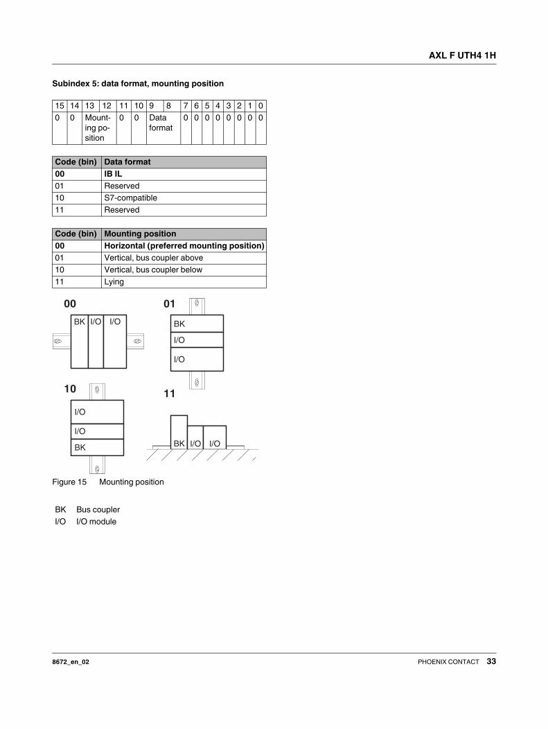
Subindex 5: data format, mounting position
Figure 15 Mounting position
15 14 13 12 11 10 9 8 7 6 5 4 3 2 1 0
0 0 Mount-
ing po-
sition
0 0 Data
format
0 0 0 0 0 0 0 0
Code (bin) Data format
00 IB IL
01 Reserved
10 S7-compatible
11 Reserved
Code (bin) Mounting position
00 Horizontal (preferred mounting position)
01 Vertical, bus coupler above
10 Vertical, bus coupler below
11 Lying
BK Bus coupler
I/O I/O module
00
11
BK I/O I/O
BK I/O I/O
10
BK
I/O
I/O
01
BK
I/O
I/O
AXL F UTH4 1H
8672_en_02 PHOENIX CONTACT 34
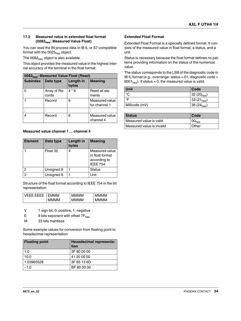
17.2 Measured value in extended float format
(0082hex: Measured Value Float)
You can read the IN process data in IB IL or S7-compatible
format with the 0025hex object.
The 0082hex object is also available.
This object provides the measured value in the highest inter-
nal accuracy of the terminal in the float format.
Measured value channel 1 ... channel 4
Structure of the float format according to IEEE 754 in the bit
representation:
Some example values for conversion from floating point to
hexadecimal representation:
Extended Float Format
Extended Float Format is a specially defined format. It con-
sists of the measured value in float format, a status, and a
unit.
Status is necessary because the float format defines no pat-
terns providing information on the status of the numerical
value.
The status corresponds to the LSB of the diagnostic code in
IB IL format (e.g., overrange: status = 01, diagnostic code =
8001hex). If status = 0, the measured value is valid.
0082hex: Measured Value Float (Read)
Subindex Data type Length in
bytes
Meaning
0 Array of Re-
cords
4 * 6 Read all ele-
ments
1 Record 6 Measured value
for channel 1
: : : :
4 Record 6 Measured value
channel 4
Element Data type Length in
bytes
Meaning
1 Float 32 4 Measured value
in float format
according to
IEEE 754
2 Unsigned 8 1 Status
3 Unsigned 8 1 Unit
VEEE EEEE EMMM
MMMM
MMMM
MMMM
MMMM
MMMM
V 1 sign bit, 0: positive, 1: negative
E 8 bits exponent with offset 7Fhex
M 23 bits mantissa
Floating point Hexadecimal representa-
tion
1.0 3F 80 00 00
10.0 41 20 00 00
1.03965528 3F 85 13 6D
- 1.0 BF 80 00 00
Unit Code
°C 32 (20hex)
°F 33 (21hex)
Millivolts (mV) 36 (24hex)
Status Code
Measured value is valid 00hex
Measured value is invalid Other
AXL F UTH4 1H
8672_en_02 PHOENIX CONTACT 35
17.3 Minimum process data value
(0083hex: PD Min)
Object 0083hex can be used to read the minimum process
data values.
The values are initialized after each parameterization. The
highest value is assigned for the minimum process data
value.
PD Min = 7FFF 7FFF 7FFF 7FFF 7FFFhex
On every analog conversion, the PD Min value is compared
with the current measured values and overwritten if neces-
sary.
17.4 Maximum process data value
(0084hex: PD Max)
Object 0084hex can be used to read the maximum process
data values.
The values are initialized after each parameterization. The
lowest value is assigned for the maximum process data
value.
PD Max = 8000 8000 8000 8000 8000hex
On every analog conversion, the PD Max value is compared
with the current measured values and overwritten if neces-
sary.
0083hex: PD Min (Read)
Subindex Data type Length in
bytes
Meaning
0 Array of Inte-
ger 16
5 * 2 Read all ele-
ments
1 Integer 16 2 Minimum pro-
cess data value
channel 1
: : : :
4 Integer 16 2 Minimum pro-
cess data value
channel 4
5 Integer 16 2 Minimum pro-
cess data value
voltage input
0084hex: PD Max (Read)
Subindex Data type Length in
bytes
Meaning
0 Array of Inte-
ger 16
5 * 2 Read all ele-
ments
1 Integer 16 2 Maximum pro-
cess data value
channel 1
: : : :
4 Integer 16 2 Maximum pro-
cess data value
channel 4
5 Integer 16 2 Maximum pro-
cess data value
voltage input
AXL F UTH4 1H
8672_en_02 PHOENIX CONTACT 36
17.5 Local adjust values (008Fhex)
This object supports a channel-specific path calibration function for maximum accuracy. This means, for example, that you
can finely tune the tolerances by means of the TC connecting cables and the sensors.
The calibration data is permanently stored on the module.
The object contains the temperature offset of the cold junction with reference to each channel in IB IL format with a resolution
of 0.1°C.
Example:
Channel 1 is measuring +2.0°C too high.
A negative offset of -2.0°C is required to correct this error.
In IB IL format, -2 °C corresponds to a value of -20dec = FFEChex.
17.6 Channel Scout (0090hex)
This object is used to quickly find a channel.
The function is terminated automatically after five minutes if
you do not deactivate the Channel Scout processes. The
flashing overrides all diagnostic messages of the selected
channel. When a channel is parameterized, the Channel
Scout function is aborted.
008Fhex: local adjust values (read, write)
Subindex Data type Length in
bytes
Meaning Contents Default value
0 Var 4 * 2 Local adjust values
Element Data type Length in
bytes
Meaning Contents Default value
1 Var 2 Temperature offset
channel 1
-20.0 °C ... +20.0 °C
(-200dec ... +200dec)
0000hex
: : : : : :
4 Var 2 Temperature offset
channel 4
-20.0 °C ... +20.0 °C
(-200dec ... +200dec)
0000hex
0090hex: channel scout (read, write)
Subindex Data type Length in
bytes
Meaning Contents
0 Var 1 Channel Scout 0 Disable all channel scout processes
1 ... 4 Green LED of the channel is flash-
ing at 0.5 Hz (1 second ON, 1 sec-
ond OFF)
AXL F UTH4 1H
8672_en_02 37PHOENIX CONTACT GmbH & Co. KG • 32823 Blomberg • Germany
phoenixcontact.com
18 Writing the analog values over the
PDI channel
PDI = Parameters, Diagnostics and Information
To set the temperature of the external cold junction via the
PDI channel rather than in the process data, you must
change the exclusive right first.
To do this, proceed as follows:
• Write the ASCII string "Superuser" to the "Password"
(001Dhex) object.
• Write the value 01hex to the “Request exclusive write ac-
cess” object (0027hex).
You may now write to the "Output process data" (0026hex)
object.
19 Device descriptions
The device is described in the device description files.
The device descriptions for controllers from Phoenix Con-
tact are included in PC Worx and the corresponding service
packs.
The device description files for other systems are available
for download at phoenixcontact.net/products in the down-
load area of the bus coupler used.