323
Axxess Administrator’s Guide ®

AxxessAdministrator’s Guide
®

VOIC
E M
AIL
AD
MIN
ISTR
ATO
R F
EATU
RES
TO R
ECO
RD
A B
RO
AD
CA
ST M
ESSA
GE
—C
all t
he v
oice
mai
l ext
ensi
on n
umbe
r.—
Pres
s ,
then
ent
er t
he s
yste
m a
dmin
istra
tor
mai
lbox
num
ber
and
pass
-w
ord.
—Pr
ess
, the
n pr
ess
.—
Rec
ord
your
mes
sage
. —
Whe
n yo
u ha
ve c
ompl
eted
you
r m
essa
ge, h
ang
up O
R pr
ess
for
mor
eop
tions
.
TO P
ERFO
RM
MA
ILB
OX
MA
INTE
NA
NC
E:—
Cal
l the
voi
ce m
ail e
xten
sion
num
ber.
—Pr
ess
, th
en e
nter
the
sys
tem
adm
inis
trato
r m
ailb
ox n
umbe
r an
d pa
ss-
wor
d.—
Pres
s , t
hen
pres
s .
—D
ial
the
mai
lbox
, ext
ensi
on I
D,
or g
roup
lis
t nu
mbe
r to
be
prog
ram
med
.Pr
ogra
m th
e pe
rson
al o
ptio
ns, f
ollo
win
g th
e pr
ompt
s, as
usu
al.
TO IM
POR
T A
FA
X D
OC
UM
ENT:
—U
sing
a fa
x m
achi
ne, c
all t
he v
oice
mai
l ext
ensi
on.
—Pr
ess
and
then
ent
er th
e sy
stem
adm
inis
trato
r mai
lbox
num
ber a
nd p
ass-
wor
d.—
Pres
s , t
hen
pres
s .
—En
ter t
he fa
x do
cum
ent n
umbe
r.If
the
docu
men
t num
ber
does
not
alre
ady
exis
t, pr
ess
if th
e nu
mbe
r is
corr
ect O
R pr
ess
and
re-r
ente
r the
num
ber.
If th
e do
cum
ent n
umbe
r al
read
y ex
ists
, Pre
ss
to
repl
ace
the
docu
men
tO
R pr
ess
to e
nter
ano
ther
num
ber.
If th
e do
cum
ent i
s be
ing
sent
, upd
ated
, or
dele
ted,
that
num
ber
cann
ot b
eus
ed ri
ght n
ow. E
nter
a n
ew n
umbe
r or h
ang
up.
If yo
u di
d no
t ent
er a
val
id n
umbe
r, en
ter a
new
num
ber.
—W
hen
prom
pted
, pre
ss S
TART
on
your
fax
mac
hine
.—
Whe
n th
e fa
x tra
nsm
issi
on is
com
plet
e, p
ress
to
con
tinue
impo
rting
doc
-um
ents
, or p
ress
to
exi
t.
QU
ICK
REF
EREN
CE
GU
IDE
TOSY
STEM
AN
D V
OIC
E M
AIL
A
DM
INIS
TRA
TOR
FEA
TUR
ESTh
ese
are
the
basi
c in
stru
ctio
ns fo
r the
mos
t fre
quen
tly u
sed
syst
em a
dmin
istra
-to
r and
voi
ce m
ail a
dmin
istra
tor f
eatu
res.
For d
etai
led
info
rmat
ion
on th
ese
fea-
ture
s, re
fer t
o th
e Ad
min
istr
ator
’s G
uide
.
SYST
EM A
DM
INIS
TRAT
OR
FEA
TUR
ESTO
PLA
CE
THE
SYST
EM IN
NIG
HT
OR
DA
Y M
OD
E:—
Whi
le o
n-ho
ok, e
nter
.
TO P
LAC
E A
SIN
GLE
NO
DE
IN D
AY
OR
NIG
HT
MO
DE:
—W
hile
on-
hook
, en
ter
(
Enab
le N
etw
ork
Nig
ht M
ode)
OR
ente
r
(En
able
Net
wor
k D
ay M
ode)
. The
n en
ter
the
desi
red
node
num
ber.
TO S
ET S
YSTE
M O
R N
ETW
OR
K D
ATE
AN
D T
IME:
—W
hile
on-
hook
, ent
er
(S
yste
m D
ate/
Tim
e) O
R en
ter
(Net
wor
k D
ate/
Tim
e).
—U
se t
he d
ialp
ad b
utto
ns t
o en
ter
the
mon
th, d
ay, a
nd y
ear.
(For
exa
mpl
e,pr
ess
0103
00 f
or J
anua
ry 3
, 20
00.)
OR
pres
s t
o sk
ip a
head
with
out
chan
ging
the
date
.—
Use
the
dial
pad
butto
ns to
ent
er th
e tim
e in
hou
rs a
nd m
inut
es. (
For e
xam
-pl
e, e
nter
090
0 fo
r 9:
00.)
OR
pres
s tw
ice
to e
xit w
ithou
t cha
ngin
g th
etim
e.—
If th
e sy
stem
is se
t for
12-
hour
dis
play
form
at, p
ress
fo
r AM
or p
ress
fo
r PM
.
TO S
YNC
HR
ON
IZE
NET
WO
RK
TIM
E:W
hile
on-
hook
, ent
er
.
TO R
ESPO
ND
TO
AN
ALA
RM
MES
SAG
E:—
Whe
n a
min
or a
larm
indi
catio
n ap
pear
s, w
rite
dow
n th
e al
arm
info
rmat
ion.
—W
hile
on-
hook
, cle
ar th
e al
arm
by
ente
ring
(
Cle
ar S
yste
mA
larm
) OR
ente
ring
(C
lear
Net
wor
k A
larm
).—
Look
up
the
alar
m i
n th
e A
dmin
istra
tor’s
Gui
de a
nd t
ake
the
appr
opria
teac
tion.
91
#
92
94
#
3
#
3
#
98
60
98
61
98
62
98
00
98
10
#
#
12
98
11
98
50
98
51
Part
No.
835
.246
1-3
©In
ter-T
el, I
nc. J
une
2003
prin
ted
in U
S

TO P
RO
GR
AM
SYS
TEM
SPE
ED-D
IAL
NU
MB
ERS:
—W
hile
on-
hook
, ent
er
.
—En
ter t
he sp
eed-
dial
loca
tion
code
(000
-999
). —
To c
hang
e or
pro
gram
the
nam
e: E
nter
the
desi
red
nam
e fo
r th
e sp
eed-
dial
num
ber:
In n
umer
ic m
ode,
the
dial
pad
butto
ns a
re u
sed
to e
nter
num
bers
0-9
, the
bu
tton
is u
sed
for e
nter
ing
a hy
phen
, and
the
but
ton
is u
sed
for e
nter
ing
a co
lon.
In a
lpha
num
eric
mod
e, d
ialp
ad b
utto
ns a
re u
sed
to e
nter
the
desi
red
lette
rs,
num
bers
, and
pun
ctua
tion.
The
num
ber o
f tim
es a
but
ton
is p
ress
ed d
eter
-m
ines
whi
ch c
hara
cter
is e
nter
ed. W
hen
adjo
inin
g ch
arac
ters
are
loca
ted
unde
r the
sam
e bu
tton,
pre
ss
to a
dvan
ce to
the
next
cha
ract
er. R
efer
to th
e fo
llow
ing
char
t to
prog
ram
info
rmat
ion
in a
lpha
num
eric
mod
e. (N
ote
that
lette
rs c
orre
spon
d to
the
lette
rs p
rinte
d on
the
dial
pad
butto
ns.)
To e
rase
the
cur
rent
nam
e an
d le
ave
it bl
ank:
Pre
ss
rep
eate
dly
until
the
nam
e is
era
sed.
The
n pr
ess
.
To le
ave
the
nam
e th
e sa
me:
Pre
ss
.—
Ente
r the
num
ber (
up to
48
digi
ts) t
o be
stor
ed.
—Pr
ess
.
*The
cha
ract
er a
vaila
ble
depe
nds o
n th
e so
ftwar
e ve
rsio
n.
NO
TES
NU
MB
ER O
F TI
MES
BU
TTO
N IS
PR
ESSE
D
BU
TTO
N1
23
45
67
89
1011
ENG
LISH
CH
AR
AC
TER
SK
ATA
KA
NA
CH
AR
AC
TER
S1
-&
()
1A
IU
EO
a
2A
BC
'2
KAKI
KUKE
KOi
3D
EF
!3
SASH
ISU
SESO
u
4G
HI
*4
TAC
HI
TSU
TETO
e
5J
KL
# or
/*5
NA
NI
NU
NE
NO
o
6M
NO
Ñ o
r #*
6H
AH
IFU
HE
HO
tsu
7P
QR
S7
MA
MI
MU
ME
MO
ya
8T
UV
?8
YAYU
YO.
,yu
9W
XY
Z9
RA
RI
RU
RE
RO
yo
0@
:.
,0
WA
WO
Npa
balo
ng
98
01
#
FWD
MU
TE
# #
#

Part Number550.8001
Issue 8.0, June 2003
©Inter-Tel, Inc. June 2003 printed in US
ADMINISTRATOR’S GUIDE
AXXESS®


NOTICE
This Inter-Tel® Axxess® Administrator’s Guide is released by INTER-TEL, INC. as a guide for systemand voice mail administrators. It provides information necessary to properly administer the system.
The contents of this guide, which reflect current INTER-TEL standards, are subject to revision or changewithout notice. Some features or applications mentioned may require a future release and are not avail-able in the initial release. Future product features and applications are subject to availability and cost.Some features or applications may require additional hardware and/or specific software. Software pack-ages released after the publication of this guide will be documented in addenda to the guide or succeed-ing issues of the guide.
For additional information, please contact you local INTER-TEL service representative.
For sales, service, or technical support,contact your local authorized Inter-Tel dealer.
If you have any questions or comments regarding this manual or other technical documentation, contact
Inter-Tel’s Technical Publications Department at: [email protected]
All products and services mentioned in this publication are the trademarks, service marks, registeredmarks, or registered service marks of their respective owners.
Inter-Tel® is a registered trademark of Inter-Tel, Incorporated.Axxess®, Executone®, and Inside Track® are registered trademarks of Inter-Tel, Incorporated.
IBM® and OS/2® Warp are registered trademarks of International Business Machines Corporation.
MS-DOS® and Microsoft® Windows® are registered trademarks of Microsoft Corporation.AudioCodes™ is a trademark of AudioCodes Ltd.


CONTENTS PAGE
Table of ContentsAXXESS® ADMINISTRATOR’S GUIDE — June 2003
Table of Contents
FCC Regulations . . . . . . . . . . . . . . . . . . . . . . . . . . . . . . . . . . . . . . . . . . . . . . . . . . . . viiiSafety Regulations. . . . . . . . . . . . . . . . . . . . . . . . . . . . . . . . . . . . . . . . . . . . . . . . . . . . xiIntroduction 1
Introduction . . . . . . . . . . . . . . . . . . . . . . . . . . . . . . . . . . . . . . . . . . . . . . . . . . . . . . . . . . . . . . 2Telephone System. . . . . . . . . . . . . . . . . . . . . . . . . . . . . . . . . . . . . . . . . . . . . . . . . . . . . . . . . . 2Voice Processor . . . . . . . . . . . . . . . . . . . . . . . . . . . . . . . . . . . . . . . . . . . . . . . . . . . . . . . . . . . 4
Administrator Procedures 7
Introduction . . . . . . . . . . . . . . . . . . . . . . . . . . . . . . . . . . . . . . . . . . . . . . . . . . . . . . . . . . . . . . 8System Administrator Features . . . . . . . . . . . . . . . . . . . . . . . . . . . . . . . . . . . . . . . . . . . . . . 8Programming and Using DSS/BLF Buttons . . . . . . . . . . . . . . . . . . . . . . . . . . . . . . . . . . . 37Voice Mail Administrator Features . . . . . . . . . . . . . . . . . . . . . . . . . . . . . . . . . . . . . . . . . . 40
System Hardware 65
Introduction . . . . . . . . . . . . . . . . . . . . . . . . . . . . . . . . . . . . . . . . . . . . . . . . . . . . . . . . . . . . . 66Station Instruments . . . . . . . . . . . . . . . . . . . . . . . . . . . . . . . . . . . . . . . . . . . . . . . . . . . . . . 67Optional System Equipment . . . . . . . . . . . . . . . . . . . . . . . . . . . . . . . . . . . . . . . . . . . . . . . 92
System Features 95
Introduction . . . . . . . . . . . . . . . . . . . . . . . . . . . . . . . . . . . . . . . . . . . . . . . . . . . . . . . . . . . . 100Access to the Features . . . . . . . . . . . . . . . . . . . . . . . . . . . . . . . . . . . . . . . . . . . . . . . . . . . . 100Attendant Stations . . . . . . . . . . . . . . . . . . . . . . . . . . . . . . . . . . . . . . . . . . . . . . . . . . . . . . 113Hunt Groups. . . . . . . . . . . . . . . . . . . . . . . . . . . . . . . . . . . . . . . . . . . . . . . . . . . . . . . . . . . . 115Trunk Features . . . . . . . . . . . . . . . . . . . . . . . . . . . . . . . . . . . . . . . . . . . . . . . . . . . . . . . . . 132Inter-Tel Phone Features . . . . . . . . . . . . . . . . . . . . . . . . . . . . . . . . . . . . . . . . . . . . . . . . . 147Multilingual Capability . . . . . . . . . . . . . . . . . . . . . . . . . . . . . . . . . . . . . . . . . . . . . . . . . . 155Intercom Calls . . . . . . . . . . . . . . . . . . . . . . . . . . . . . . . . . . . . . . . . . . . . . . . . . . . . . . . . . . 159Inter-Station Messages . . . . . . . . . . . . . . . . . . . . . . . . . . . . . . . . . . . . . . . . . . . . . . . . . . . 165Off-Hook Voice Announce (OHVA) . . . . . . . . . . . . . . . . . . . . . . . . . . . . . . . . . . . . . . . . 170Outside Calls . . . . . . . . . . . . . . . . . . . . . . . . . . . . . . . . . . . . . . . . . . . . . . . . . . . . . . . . . . . 172Placing Calls On Hold . . . . . . . . . . . . . . . . . . . . . . . . . . . . . . . . . . . . . . . . . . . . . . . . . . . 181
Page v

Table of ContentsAXXESS® ADMINISTRATOR’S GUIDE — June 2003
CONTENTS PAGE
Call Waiting . . . . . . . . . . . . . . . . . . . . . . . . . . . . . . . . . . . . . . . . . . . . . . . . . . . . . . . . . . . . 184Call Transfer . . . . . . . . . . . . . . . . . . . . . . . . . . . . . . . . . . . . . . . . . . . . . . . . . . . . . . . . . . . 186Call Screening . . . . . . . . . . . . . . . . . . . . . . . . . . . . . . . . . . . . . . . . . . . . . . . . . . . . . . . . . . 189Reverse Transfer . . . . . . . . . . . . . . . . . . . . . . . . . . . . . . . . . . . . . . . . . . . . . . . . . . . . . . . . 190Conference Calls . . . . . . . . . . . . . . . . . . . . . . . . . . . . . . . . . . . . . . . . . . . . . . . . . . . . . . . . 191Record-A-Call . . . . . . . . . . . . . . . . . . . . . . . . . . . . . . . . . . . . . . . . . . . . . . . . . . . . . . . . . . 196Agent Help . . . . . . . . . . . . . . . . . . . . . . . . . . . . . . . . . . . . . . . . . . . . . . . . . . . . . . . . . . . . . 198System Forwarding . . . . . . . . . . . . . . . . . . . . . . . . . . . . . . . . . . . . . . . . . . . . . . . . . . . . . . 201Call Forwarding . . . . . . . . . . . . . . . . . . . . . . . . . . . . . . . . . . . . . . . . . . . . . . . . . . . . . . . . 208Speed Dialing . . . . . . . . . . . . . . . . . . . . . . . . . . . . . . . . . . . . . . . . . . . . . . . . . . . . . . . . . . . 213Intercom, Speed-Dial, and Feature Code Directory . . . . . . . . . . . . . . . . . . . . . . . . . . . 221House Phone . . . . . . . . . . . . . . . . . . . . . . . . . . . . . . . . . . . . . . . . . . . . . . . . . . . . . . . . . . . 224Redialing . . . . . . . . . . . . . . . . . . . . . . . . . . . . . . . . . . . . . . . . . . . . . . . . . . . . . . . . . . . . . . 226Redirect Call . . . . . . . . . . . . . . . . . . . . . . . . . . . . . . . . . . . . . . . . . . . . . . . . . . . . . . . . . . . 228Paging . . . . . . . . . . . . . . . . . . . . . . . . . . . . . . . . . . . . . . . . . . . . . . . . . . . . . . . . . . . . . . . . . 229Remove from Paging . . . . . . . . . . . . . . . . . . . . . . . . . . . . . . . . . . . . . . . . . . . . . . . . . . . . 230Do-Not-Disturb . . . . . . . . . . . . . . . . . . . . . . . . . . . . . . . . . . . . . . . . . . . . . . . . . . . . . . . . . 230Do-Not-Disturb Override . . . . . . . . . . . . . . . . . . . . . . . . . . . . . . . . . . . . . . . . . . . . . . . . . 234Remote Feature Programming . . . . . . . . . . . . . . . . . . . . . . . . . . . . . . . . . . . . . . . . . . . . 235Default Station . . . . . . . . . . . . . . . . . . . . . . . . . . . . . . . . . . . . . . . . . . . . . . . . . . . . . . . . . . 239Hookflash . . . . . . . . . . . . . . . . . . . . . . . . . . . . . . . . . . . . . . . . . . . . . . . . . . . . . . . . . . . . . . 240Reminder Messages . . . . . . . . . . . . . . . . . . . . . . . . . . . . . . . . . . . . . . . . . . . . . . . . . . . . . 241Record Keeping and Maintenance Features . . . . . . . . . . . . . . . . . . . . . . . . . . . . . . . . . 243
Voice Processing Features 251
Introduction . . . . . . . . . . . . . . . . . . . . . . . . . . . . . . . . . . . . . . . . . . . . . . . . . . . . . . . . . . . . 253Automated Attendant . . . . . . . . . . . . . . . . . . . . . . . . . . . . . . . . . . . . . . . . . . . . . . . . . . . . 254Call Routing Announcement . . . . . . . . . . . . . . . . . . . . . . . . . . . . . . . . . . . . . . . . . . . . . . 258Fax-On-Demand . . . . . . . . . . . . . . . . . . . . . . . . . . . . . . . . . . . . . . . . . . . . . . . . . . . . . . . . 261Directories . . . . . . . . . . . . . . . . . . . . . . . . . . . . . . . . . . . . . . . . . . . . . . . . . . . . . . . . . . . . . 263Record-A-Call . . . . . . . . . . . . . . . . . . . . . . . . . . . . . . . . . . . . . . . . . . . . . . . . . . . . . . . . . . 266Scheduled Time-Based Application Routing (STAR) . . . . . . . . . . . . . . . . . . . . . . . . . . 267SMDR Information Storage and Retrieval . . . . . . . . . . . . . . . . . . . . . . . . . . . . . . . . . . 268Voice Mail . . . . . . . . . . . . . . . . . . . . . . . . . . . . . . . . . . . . . . . . . . . . . . . . . . . . . . . . . . . . . 269
Page vi

Table of ContentsAXXESS® ADMINISTRATOR’S GUIDE — June 2003
CONTENTS PAGE
Using Voice Mail . . . . . . . . . . . . . . . . . . . . . . . . . . . . . . . . . . . . . . . . . . . . . . . . . . . . . . . . 276Unified Messaging . . . . . . . . . . . . . . . . . . . . . . . . . . . . . . . . . . . . . . . . . . . . . . . . . . . . . . . 288Automatic Fax Detection . . . . . . . . . . . . . . . . . . . . . . . . . . . . . . . . . . . . . . . . . . . . . . . . . 292
Index 293
Default Feature Codes 305
Voice Mail Flowchart. . . . . . . . . . . . . . . . . . . . . . . . . . . . . . . . . . . . . . . . . . . . . . . . . . . . . 307
Page vii

FCC RegulationsAXXESS® ADMINISTRATOR’S GUIDE – June 2003
FCC Regulations
Important1. This equipment complies with Part 68 of FCC rules. On the side of the equipment cabi-
net is a label that contains, among other information, the FCC registration number andringer equivalence number (REN) for this equipment. Customers connecting this equip-ment to the telephone network shall, before such connection is made, give notice to thetelephone company of the particular line(s) to which such connection is to be made, andshall provide the telephone company with the following information:
— Complies with Part 68 of FCC rules
— FCC registration number: BE2USA-64572-MF-E (for MF-rated systems),BE2USA- 64573-KF-E (for KF-rated systems), or BE2USA-24359-PF-E (for PBXsystems)
— USOC numbers of required interface jacks (see chart on next page)
— Service order code (SOC), as applicable (see chart on next page)
— Facility interface code (FIC) (see chart on next page)
— Ringer equivalence number (REN), as applicable (see chart on next page)
NOTE: The REN is used to determine the quantity of devices which may be con-nected to the telephone line. Excessive RENs on the telephone line may result inthe devices not ringing in response to an incoming call. In most, but not all areas,the sum of the RENs should not exceed five (5.0). To be certain of the number ofdevices that may be connected to the line, as determined by the total RENs, contactthe telephone company to determine the maximum REN for the calling area.
The telephone company should also be given notice upon final disconnection of thisequipment from the particular line(s).
It is also the responsibility of the customer to provide the telephone company with reg-istration numbers of any other devices which are configured for connection to the tele-phone network.
2. This equipment cannot be used on public coin service provided by the telephone com-pany. Connection to party line service is subject to state tariffs. (Contact the state publicutility commission, public service commission, or corporation commission for informa-tion.)
3. If this equipment causes harm to the telephone network, the telephone company willnotify the customer in advance that service may be temporarily discontinued. But ifadvance notice is not practical, the telephone company will notify the customer as soonas possible. Also, the customer will be advised of the right to file a complaint with theFCC, if necessary.
4. The telephone company may make changes in its facilities, equipment, operations, orprocedures which may affect the operation of this equipment. If so, the customer shallbe given advance notice so that any necessary modifications can be made in order tomaintain uninterrupted service.
Page viii

FCC RegulationsAXXESS® ADMINISTRATOR’S GUIDE – June 2003
5. If trouble is experienced with this equipment, contact a local authorized factory servicerepresentative for repairs and/or warranty information. The customer, users, and unau-thorized technicians should not repair, make adjustments to, or attempt to service thisequipment in any way.
6. In the event of trouble with the telephone line(s), this equipment must be disconnectedfrom the telephone line(s). If trouble ceases, the equipment must be repaired by anauthorized factory service representative. If the trouble continues to occur with theequipment disconnected, the telephone company should be notified that they have aproblem. If this is the case, repairs or adjustments made by the telephone company willbe made at their expense.
7. Allowing this equipment to be operated in such a manner as to not provide properanswer supervision signaling is in violation of Part 68 of FCC rules. This equipmentreturns answer supervision signals to the public telephone network when: answered bythe called station, answered by the attendant, routed to a recorded announcement thatcan be administered by the equipment user, and routed to a dial prompt. This equipmentalso returns answer supervision on all DID calls forwarded back to the public telephonenetwork. Permissible exceptions are: a call is unanswered, busy tone is received, andreorder tone is received.
8. This equipment is capable of providing users access to interstate providers of operatorservices through the use of equal access codes. Failure to provide equal access capabili-ties is a violation of the Telephone Operator Consumer Services Improvement Act of1990 and Part 68 of the FCC Rules.
TYPE OF PORTINTERFACE
FACILITY INTERFACE CODE (FIC)
RINGER EQUIV ALENCE NO. (REN)
SERVICE ORDER CODE (SOC)
USOC JACKCONNECTOR
2-Wire Loop 02LS2 0.6B – RJ21X
2-Wire Loop/Ground 02LS2/02GS2 3.6B/4.4B – RJ21X
2-Wire Ground 02GS2 0.6B – RJ21X
OPX Class C* 0L13C – 9.0F RJ11C, RJ21X
2-Wire DID** 02RV2-T 0.0B AS.2 RJ11C, RJ21XD4 Superframe/AMI 04DU9-BN – 6.0Y RJ48C
D4 Superframe with B8ZS
04DU9-DN – 6.0Y RJ48C
ExtendedSuperframe (ESF)
04DU9-1KN – 6.0Y RJ48C
ESF with B8ZS 04DU9-1SN – 6.0Y RJ48C
Primary Rate ISDN 04DU9-1SN – 6.0Y RJ48C
* Also interfaces with Class A and B.** When using T1 facilities to provide DID service, do not use the DID facility interface code (FIC); instead, pro-
vide the telephone company with DID answer supervision code “AS.2” and the FIC for the requested T1 service.
Page ix

FCC RegulationsAXXESS® ADMINISTRATOR’S GUIDE – June 2003
NoticeThis equipment generates and uses radio frequency energy and if not installed and used prop-erly, that is, in strict accordance with the manufacturer’s instructions, may cause interference toradio and television reception. It has been type tested and found to comply with the limits for aClass A computing device in accordance with the specifications in Subpart J of Part 15 of FCCRule. Operation of this equipment in a residential area may cause unacceptable interference toradio and TV reception requiring the operator to take whatever steps are necessary to correctthe interference. However, there is no guarantee that interference will not occur in a particularinstallation. If this equipment does cause interference to radio or television reception, whichcan be determined by turning the equipment off and on, the user is encouraged to try to correctthe interference by one or more of the following measures:
• Reorient the receiving antenna
• Relocate the equipment cabinet with respect to the receiver
• Check that the equipment cabinet and receiver are not on the same circuit; the equip-ment cabinet must be powered from an isolated, dedicated AC outlet
If necessary, the user should consult the dealer or an experienced radio/television technicianfor additional suggestions. The user may find the following booklet prepared by the FCC help-ful: “How to Identify and Resolve Radio-TV Interference Problems”
This booklet is available from the U.S. Government Printing Office, Washington, D.C. 20402,Stock No. 004-000-00398-5.
If RFI problems persist, contact Inter-Tel Customer Support.
The Axxess® system is now product safety certified by Canadian Standards Association (CSA)for use in both the United States and Canada.
CAUTION
THE TELEPHONE INSTRUMENTS SPECIFICALLY DESIGNED FOR THIS SYSTEMHAVE HEARING-AID COMPATIBLE HANDSETS THAT ARE IN COMPLIANCE WITHSECTION 68.316 OF THE FCC RULES.
THE IP SLA COMPLIES WITH UL1950/CSA950 AND EN 60950 STANDARDS ANDCOMPLIES WITH EN 55022 AND PART 15 OF FCC RULES.
Page x

Safety RegulationsAXXESS® ADMINISTRATOR’S GUIDE – June 2003
Safety Regulations
Important Safety Instructions
The following safety information is reprinted from UL 1459. When using your telephoneequipment, basic safety precautions should always be followed to reduce the risk of fire, elec-tric shock, and injury to persons, including the following:
1. Read and understand all instructions.
2. Follow all warnings and instructions marked on the product.
3. Unplug this product from the wall outlet before cleaning. Do not use liquid cleaners oraerosol cleaners. Use a damp cloth for cleaning.
4. Do not use this product near water (for example, in a wet basement).
5. Do not place this product on an unstable cart, stand, or table. The product may fall,causing serious damage to the product.
6. Slots and openings in the cabinet and the back or bottom are provided for ventilation, toprotect it from overheating; these openings must not be blocked or covered. This prod-uct should never be placed near or over a radiator or heat register. This product shouldnot be placed in a built-in installation unless proper ventilation is provided.
7. This product should be operated only from the type of power source indicated in themanual. If you are not sure of the type of power source to your building, consult yourdealer or local power company.
8. This product is equipped with a three-wire grounding type plug, a plug having a third(grounding) pin. This plug will only fit into a grounding type power outlet. This is asafety feature. If you are unable to insert the plug into the outlet, contact your electri-cian to replace your obsolete outlet. Do not defeat the safety purpose of the groundingtype plug.
9. Do not allow anything to rest on the power cord. Do not locate this product where thecord will be abused by persons walking on it.
10. Do not use an extension cord with this product’s AC power cord. The AC outlet for thisproduct should not be used for any other electrical equipment.
11. Never push objects of any kind into this product through cabinet slots as they maytouch dangerous voltage points or short out parts that could result in a risk of fire orelectric shock. Never spill liquid of any kind on the product.
CAUTION
The “NRTL/C” indicator adjacent to the CSA mark on the product label signifies that theAxxess® system has been evaluated to the applicable ANSI/UL and CSA Standards for usein both the United States and Canada. NRTL (Nationally Recognized Testing Laboratory)is a designation granted by the U.S. Occupational Health and Safety Administration(OSHA) to laboratories which have been accredited to certify products to U.S. Standards.Before installation, also check the local electrical codes for important information concern-ing the installation of telephone and electronic equipment.
Page xi

Safety RegulationsAXXESS® ADMINISTRATOR’S GUIDE – June 2003
12. To reduce the risk of electric shock, do not disassemble this product, but take it to aqualified serviceman when some service or repair work is required. Opening or remov-ing covers may expose you to dangerous voltages or other risks. Incorrect reassemblycan cause electric shock when the product is subsequently used.
13. Unplug this product from the wall outlet and refer servicing to qualified service person-nel under the following conditions:
a. When the power supply cord or plug is damaged or frayed.
b. If liquid has been spilled into the product.
c. If the product has been exposed to rain or water.
d. If the product does not operate normally by following the operating instructions.Adjust only those controls that are covered by the operating instructions becauseimproper adjustment of other controls may result in damage and will often requireextensive work by a qualified technician to restore the product to normal operation.
e. If the product has been dropped or the cabinet has been damaged.
f. If the product exhibits a distinct change in performance.
14. Avoid using a telephone (other than a cordless type) during an electrical storm. Theremay be a remote risk of electric shock from lightning.
15. Do not use the telephone to report a gas leak in the vicinity of the leak.
Save These InstructionsCAUTION
This exclamation point within a triangle (which, for example, is silk-screenedon the front of the system cabinet) is intended to alert the user to the presenceof important operating and maintenance (servicing) instructions in the litera-ture accompanying the product. Be sure to read and follow all of the instruc-tions included in this manual.
!
Page xii

IntroductionAXXESS® ADMINISTRATOR’S GUIDE – June 2003
IntroductionCONTENTS PAGE
Introduction . . . . . . . . . . . . . . . . . . . . . . . . . . . . . . . . . . . . . . . . . . . . . . . . . . . . . . . . . . . . . . 2Telephone System. . . . . . . . . . . . . . . . . . . . . . . . . . . . . . . . . . . . . . . . . . . . . . . . . . . . . . . . . . 2
Networking . . . . . . . . . . . . . . . . . . . . . . . . . . . . . . . . . . . . . . . . . . . . . . . . . . . . . . . . . . . . 2System Administrator Duties . . . . . . . . . . . . . . . . . . . . . . . . . . . . . . . . . . . . . . . . . . . . . . 3
Voice Processor . . . . . . . . . . . . . . . . . . . . . . . . . . . . . . . . . . . . . . . . . . . . . . . . . . . . . . . . . . . 4Voice Mail Networks . . . . . . . . . . . . . . . . . . . . . . . . . . . . . . . . . . . . . . . . . . . . . . . . . . . . 5Voice Mail Administrator Duties . . . . . . . . . . . . . . . . . . . . . . . . . . . . . . . . . . . . . . . . . . . 6
Page 1
IntroductionAXXESS® ADMINISTRATOR’S GUIDE – June 2003
INTRODUCTION
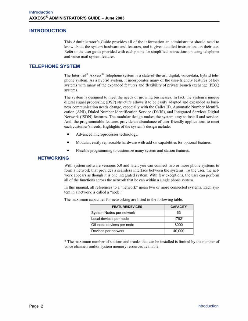
This Administrator’s Guide provides all of the information an administrator should need toknow about the system hardware and features, and it gives detailed instructions on their use.Refer to the user guide provided with each phone for simplified instructions on using telephoneand voice mail system features.
TELEPHONE SYSTEMThe Inter-Tel® Axxess® Telephone system is a state-of-the-art, digital, voice/data, hybrid tele-phone system. As a hybrid system, it incorporates many of the user-friendly features of keysystems with many of the expanded features and flexibility of private branch exchange (PBX)systems.
The system is designed to meet the needs of growing businesses. In fact, the system’s uniquedigital signal processing (DSP) structure allows it to be easily adapted and expanded as busi-ness communication needs change, especially with the Caller ID, Automatic Number Identifi-cation (ANI), Dialed Number Identification Service (DNIS), and Integrated Services DigitalNetwork (ISDN) features. The modular design makes the system easy to install and service.And, the programmable features provide an abundance of user-friendly applications to meeteach customer’s needs. Highlights of the system’s design include:
• Advanced microprocessor technology.
• Modular, easily replaceable hardware with add-on capabilities for optional features.
• Flexible programming to customize many system and station features.
NETWORKINGWith system software versions 5.0 and later, you can connect two or more phone systems toform a network that provides a seamless interface between the systems. To the user, the net-work appears as though it is one integrated system. With few exceptions, the user can performall of the functions across the network that he can within a single phone system.
In this manual, all references to a “network” mean two or more connected systems. Each sys-tem in a network is called a “node.”
The maximum capacities for networking are listed in the following table.
* The maximum number of stations and trunks that can be installed is limited by the number ofvoice channels and/or system memory resources available.
FEATURE/DEVICES CAPACITY
System Nodes per network 63Local devices per node 1792*Off-node devices per node 8000Devices per network 40,000
Page 2 Introduction

IntroductionAXXESS® ADMINISTRATOR’S GUIDE – June 2003
SYSTEM ADMINISTRATOR DUTIESAs a system administrator, you can provide the following services:
• Place the local phone system or other systems in the network in night or day mode
• Set the date and time of the local system
• Set the network date and time and re-synchronize clocks in the network.
• Make database changes (see page 11 for a list of programming areas)
• Program system speed-dial numbers on the local system
• Receive and clear displayed system and network alarms
• Use diagnostic mode features to:— Freeze and unfreeze database history on the local system or other systems in the
network
— Print error logs
— Seize specific devices for troubleshooting purposes
Administrator features are described in detail beginning on page 8.
Any Inter-Tel phone can be designated as an administrator station through Database Program-ming. All designated administrator stations should be equipped with display phones to showsystem alarms and make programming easier.
NOTE: Single-line sets can not be used as an administrator station.
Page 3System Administrator Duties

IntroductionAXXESS® ADMINISTRATOR’S GUIDE – June 2003
VOICE PROCESSOR
The system Voice Processor can be used for any of the following applications:
• Voice Mail: This application handles all calls that are directed to voice mail (other thanthrough the Message Notification/Retrieval application) by subscribers and non-sub-scribers. Callers will hear the main company greeting, followed by a menu of availableoptions. Stations can forward or transfer calls directly to their mailbox.
• Message Notification/Retrieval: The Message Notification/Retrieval application pro-vides voice mail message notification and quick mailbox access.
• Directory Services: Directory services provide callers with a list of mailboxes andextension IDs.
• Automated Attendant: The automated attendant is a programmable feature that can beused to provide automated call answering service. Calls can transfer, forward, ordirectly ring in to an automated attendant. When an automated attendant answers a call,it plays a recording that gives dialing instructions. After hearing the recording (or at anytime while it is playing), the caller may then dial an extension or mailbox number.
• Automated Attendant Recall Destination: If a call, that is transferred by the auto-mated attendant, is not answered before the Transfer Voice Processor timer expires, thecall recalls the Automated Attendant Recall Destination. The Recall Destinationannounces that the station is unavailable and allows the caller to leave a message (if thestation has an associated mailbox) or dial another extension.
• Call Routing Announcement: Call Routing Announcements can be used two ways:— A Call Routing Announcement application can be used in place of a playback
device. The playback device function is especially useful for programming huntgroup announcement and overflow stations. When called, the Call RoutingAnnouncement application will play a recording and then hang up.
— The Call Routing Announcement application can use Digit Translation whichallows the caller to press a single digit for access to a mailbox, a fax-on-demandfunction, or a station or hunt group that has an associated mailbox or extension ID.Digit translation can be programmed for each digit 0-9, #, and *, plus a Timeoutthat is used when the caller does not enter a digit. Each digit can lead to a “digittranslation node” that has its own digit translation values. This layered Call Rout-ing Announcement digit translation creates a “tree” of programmable digit transla-tion nodes.
Page 4 Voice Processor

IntroductionAXXESS® ADMINISTRATOR’S GUIDE – June 2003
• Record-A-Call: This feature allows a station user to record an ongoing call in a voicemailbox message. When a station user enters the Record-A-Call feature code, the sys-tem places a call to the station’s assigned Record-A-Call application. When the applica-tion answers, the system sets up a conference call with the station’s Record-A-Callmailbox. If programmed, the mailbox plays a greeting to indicate that the recording isin progress.
• STAR: The Scheduled Time-Based Application Routing (STAR) enhances the pro-grammability of the voice mail application greetings. With STAR, applications can beprogrammed to play alternative greetings for holidays and weekends. A STAR applica-tion is a table of up to 20 entries, that serves as a “routing table” which tells the VoiceProcessor which application will be used, based on day and time information in thetable. (The applications are programmed to play the greetings, not the STAR applica-tion. The STAR routes the call to the right application.)
• Station Message Detail Recording (SMDR) Information Storage: SMDR informa-tion can be stored on the Voice Processor’s hard disk and then processed using callrecord sorting software, such as Inter-Tel’s Inside Track®.
VOICE MAIL NETWORKSA Voice Processor can be installed on any or all nodes in the system network. These Voice Pro-cessors can also be networked together to allow a caller to leave a message on the local VoiceProcessor for a mailbox located on another Voice Processor in the network.
The maximum capacities of the network are listed in the following table.
a This is the maximum number of nodes supported by the software. System traffic may limitthe actual number of nodes that can be supported without affecting system performance.
b This is the maximum number of mailboxes supported by the NT-based software.
FEATURE/DEVICES CAPACITY
Voice Processors per network 100a
Local or Off-Node Mailboxes and/or Extension IDs per Voice Processor node
10,000b
System Audio Interface Ports per node 40Applications per node 150Group Lists per nodeMembers per group list
10001500
Remote Message Notification Numbers per mailbox 18Audiotex Recordings per node 500Message Notification/Retrieval Applications per node 1System Passwords per node 4Time Slot Groups per node 10
Page 5Voice Mail Networks

IntroductionAXXESS® ADMINISTRATOR’S GUIDE – June 2003
VOICE MAIL ADMINISTRATOR DUTIESAs the voice mail administrator, you can use special features that are not provided to othervoice mail users. The system administrator mailbox has all standard subscriber features plusthe ability to do the following:
• Record a broadcast message
• Perform mailbox and group list maintenance
• Create and select custom audiotex recordings (voice mail company greetings, autoattendant recordings, call routing announcements, and hunt group overflow andannouncement station recordings)
• Import fax documents
• Customize voice mail prompts
Voice mail administrator features are described in detail on page 40.
Page 6 Voice Mail Administrator Duties

Administrator ProceduresAXXESS® ADMINISTRATOR’S GUIDE – June 2003
Administrator ProceduresCONTENTS PAGE
Introduction . . . . . . . . . . . . . . . . . . . . . . . . . . . . . . . . . . . . . . . . . . . . . . . . . . . . . . . . . . . . . . 8System Administrator Features . . . . . . . . . . . . . . . . . . . . . . . . . . . . . . . . . . . . . . . . . . . . . . 8
Placing the System in Night Mode. . . . . . . . . . . . . . . . . . . . . . . . . . . . . . . . . . . . . . . . . . 9Placing Nodes in Day or Night Mode . . . . . . . . . . . . . . . . . . . . . . . . . . . . . . . . . . . . . . . 9Setting System Date and Time . . . . . . . . . . . . . . . . . . . . . . . . . . . . . . . . . . . . . . . . . . . . . 9Setting Network Date and Time . . . . . . . . . . . . . . . . . . . . . . . . . . . . . . . . . . . . . . . . . . . 10Synchronize Network Time . . . . . . . . . . . . . . . . . . . . . . . . . . . . . . . . . . . . . . . . . . . . . . 11Database Programming . . . . . . . . . . . . . . . . . . . . . . . . . . . . . . . . . . . . . . . . . . . . . . . . . 11
Station Programming Using an Administrator’s Station. . . . . . . . . . . . . . . . . . . . . 13System Programming Using an Administrator’s Station . . . . . . . . . . . . . . . . . . . . 17Trunk Programming Using an Administrator’s Station . . . . . . . . . . . . . . . . . . . . . 23
System and Network Alarm Reporting . . . . . . . . . . . . . . . . . . . . . . . . . . . . . . . . . . . . . 32System Alarms . . . . . . . . . . . . . . . . . . . . . . . . . . . . . . . . . . . . . . . . . . . . . . . . . . . . 32Network Alarms . . . . . . . . . . . . . . . . . . . . . . . . . . . . . . . . . . . . . . . . . . . . . . . . . . . 32
Freezing/Unfreezing the System History . . . . . . . . . . . . . . . . . . . . . . . . . . . . . . . . . . . . 34Freezing/Unfreezing the Network History . . . . . . . . . . . . . . . . . . . . . . . . . . . . . . . . . . . 34Seizing a Device . . . . . . . . . . . . . . . . . . . . . . . . . . . . . . . . . . . . . . . . . . . . . . . . . . . . . . . 35Enabling/Disabling The Call Processing Card Modem . . . . . . . . . . . . . . . . . . . . . . . . . 36Assigning the CPC Modem to a DSS/BLF Button . . . . . . . . . . . . . . . . . . . . . . . . . . . . 37
Programming and Using DSS/BLF Buttons . . . . . . . . . . . . . . . . . . . . . . . . . . . . . . . . . . . 37Voice Mail Administrator Features . . . . . . . . . . . . . . . . . . . . . . . . . . . . . . . . . . . . . . . . . . 40
Broadcast Messages . . . . . . . . . . . . . . . . . . . . . . . . . . . . . . . . . . . . . . . . . . . . . . . . . . . . 40Mailbox/Group List Maintenance . . . . . . . . . . . . . . . . . . . . . . . . . . . . . . . . . . . . . . . . . 41Importing Fax Documents . . . . . . . . . . . . . . . . . . . . . . . . . . . . . . . . . . . . . . . . . . . . . . . 42Custom Audiotex Recordings. . . . . . . . . . . . . . . . . . . . . . . . . . . . . . . . . . . . . . . . . . . . . 43Customized Voice Mail Prompts . . . . . . . . . . . . . . . . . . . . . . . . . . . . . . . . . . . . . . . . . . 45
Page 7

Administrator ProceduresAXXESS® ADMINISTRATOR’S GUIDE – June 2003
INTRODUCTION
During database programming, any Inter-Tel phone can be designated as a system administra-tor and/or a voice mail administrator. All administrator stations should be equipped with dis-play phones to show system alarms and to make programming easier.
This section gives you all of the instructions for using the Administrator Features of the systemand voice mail.
• System Administrator Features begin below.
• Voice Mail Administrator Features begin on page 40.
A quick reference card is located in the front of this book for your convenience.
Refer to the System Features and Voice Processing Features chapters for detailed descriptionsof the system and Voice Processor and for general user procedures.
NOTE: The telephone system provides a choice between American English, British English,Spanish and Japanese prompts and displays. As an administrator, you must know which lan-guage is considered Primary and which is Secondary for the system.
SYSTEM ADMINISTRATOR FEATURES
Any display Inter-Tel phone (attendant or non-attendant) can be assigned as a telephone systemadministrator. System administrator stations provide the following services:
• Place the local node or other nodes in the network in night or day mode
• Set the date and time of the local node
• Set the network date and time and re-synchronize clocks in the network
• Make database changes (see page 11 for a list of programming areas)
• Enable, disable, and reset local and off-node Call Processing Card modems
• Program system speed-dial numbers on the local node
• Receive and clear displayed system and network alarms
• Use diagnostic mode features:
— Freeze and unfreeze the database history for the local node or any node in the net-work using programmed freeze zones
— Print error logs
— Seize specific devices for troubleshooting purposes
Any Inter-Tel phone station can be programmed to be an administrator station by the databaseprogrammer or by another administrator station.
NOTE: Single-line sets can not be used as an administrator station.
If a non-administrator station user attempts to use the administrator features, the user will hearreorder tones, and the display will show CANNOT ACCESS RESERVED FEATURE.
Page 8 Introduction

Administrator ProceduresAXXESS® ADMINISTRATOR’S GUIDE – June 2003
PLACING THE SYSTEM IN NIGHT MODE
An administrator station can place the local node in day or night mode. The day/night modedetermines which lists the system will use for trunk access, toll restriction, etc.
Night mode also affects the night transfer relays on the Options Card (OPC). The relays areactivated when the system is placed in night mode. See SPECIFICATIONS in the InstallationManual for details.
TO TURN NIGHT MODE ON OR OFF:
While on hook, enter the Night Ring On/Off feature code (9860). You hear a singleconfirmation tone. The display shows NIGHT MODE IS ON (or OFF). Then, if nightmode was turned on, the display shows THE SYSTEM IS IN NIGHT MODE until daymode is turned on.
PLACING NODES IN DAY OR NIGHT MODE
An administrator station can place one or more nodes in day or night mode. The day/nightmode determines which lists the system will use for trunk access, toll restriction, etc.
The network determines the day/night mode status of a call based on the day/night mode statusof the node where the trunk resides.
TO TURN NIGHT MODE ON:
1. While on hook, enter the Enable Network Night feature code (9861).
2. You are prompted to enter a node number. Enter the desired node number.
3. You hear a single confirmation tone. The display shows NIGHT MODE IS ON. Thenthe display shows NODE X IS IN NIGHT MODE until day mode is turned on.
TO TURN DAY MODE ON:
1. While on hook, enter the Enable Network Day feature code (9862).
2. You are prompted to enter a node number. Enter the desired node number.
3. You hear a single confirmation tone. The display shows DAY MODE IS ON.
SETTING SYSTEM DATE AND TIME
Occasionally, the system time or date needs to be reset (for example, when the system isdefaulted or for daylight-saving time). Any administrator can change the date and time thatappears on all display phones and in the SMDR reports. The day of the week is automaticallycalculated and set by the system when the date is entered.
TO SET THE SYSTEM DATE AND TIME:
NOTE: If you make a mistake, press to backspace or press or CANCEL to leave itunchanged and start over.
1. While on hook, enter the Set Date/Time feature code (9800). Your display shows DATE(current date).
If you do not need to change the date, press or ACCEPT to skip to the TIMEXX:XX prompt.
2. Use the dialpad buttons to enter the month, day, and year. For example, press 020301for February 3, 2001. When finished, the display shows TIME (current time). If youentered the date incorrectly, the display shows INVALID DATE, and you are promptedto enter a new date.
MUTE
#
Page 9Placing the System in Night Mode

Administrator ProceduresAXXESS® ADMINISTRATOR’S GUIDE – June 2003
NOTE: If using a station programmed for Japanese, enter the date as year, month,date. For example, 010203 for February 3, 2001.
If you do not need to change the time, press or ACCEPT twice to exit. The displayshows SYSTEM DATE AND TIME UPDATED.
3. Use the dialpad buttons to enter the time in hours and minutes. (For example, enter0900 for 9:00.) If you entered the time incorrectly, the display shows INVALID TIMEand you are prompted to enter a new time.
4. If the system is set for 12-hour display format, the display shows SELECT AM OR PM(AM=1 PM=2). Press (or the AM menu button) for AM or press (or the PMmenu button) for PM. The display shows SYSTEM DATE AND TIME UPDATED. Ifyou press any button other than 1 or 2, the display shows INVALID TIME and you areprompted to enter a new time.
NOTE: If using a station programmed for Japanese, the prompts will be reversed andyou will set the AM/PM before the hour and minutes.
SETTING NETWORK DATE AND TIMEOccasionally, the network time or date needs to be reset (for example, when the system isdefaulted or for daylight-saving time). Any administrator can change the date and time thatappears on all display phones and in the SMDR reports in the network. The day of the week isautomatically calculated and set by the system when the date is entered.
TO SET THE NETWORK DATE AND TIME:
NOTE: If you make a mistake, press to backspace or press or CANCEL to leave itunchanged and start over.
1. While on hook, enter the Set Network Date and Time feature code (9810). Your displayshows DATE (current date).
If you do not need to change the date, press or ACCEPT to skip to the TIMEXX:XX prompt.
2. Use the dialpad buttons to enter the month, day, and year. For example, press 020301for February 3, 2001. When finished, the display shows TIME (current time).
NOTE: If using a station programmed for Japanese, enter the date as year, month,date. For example, 010203 for February 3, 2001.
If you entered the date incorrectly, the display shows INVALID DATE, and you areprompted to enter a new date.If you do not need to change the time, press or ACCEPT twice to exit. The displayshows SYSTEM DATE AND TIME UPDATED.
3. Use the dialpad buttons to enter the time in hours and minutes. (For example, enter0900 for 9:00.)
NOTE: If using a station programmed for Japanese, the prompts will be reversed andyou will set the AM/PM before the hour and minutes.
If you entered the time incorrectly, the display shows INVALID TIME, and you areprompted to enter a new time.
#
1 2
MUTE
#
#
Page 10 Placing the System in Night Mode

Administrator ProceduresAXXESS® ADMINISTRATOR’S GUIDE – June 2003
4. If the node is set for 12-hour display format, the display shows SELECT AM OR PM(AM=1 PM=2). Press (or the AM menu button) for AM or press (or the PMmenu button) for PM. The display shows SYSTEM DATE AND TIME UPDATED. Ifyou press any button other than 1 or 2, the display shows INVALID TIME, and you areprompted to enter a new time.
SYNCHRONIZE NETWORK TIME
Administrators can synchronize the minutes past the hour across the network without changingthe hour. This is useful when the nodes are in different time zones.
NOTE: If a node's time is off by more than 30 minutes, synchronizing the minutes may causethe hour to change. Also, network time is automatically synchronized every day at 12:30 AM(00:30), using the time setting on the node with the lowest number.
An administrator can synchronize the clocks in all nodes in the network using the followingprocedure.
TO SYNCHRONIZE NETWORK TIME:
While on hook, enter the Synchronize Network Time feature code (9811). You hear aconfirmation tone, and the display shows NETWORK TIME SYNCHRONIZED.
DATABASE PROGRAMMING
Any administrator station can perform database programming using an Inter-Tel phone. How-ever, it requires a display phone, and an Executive Display, Professional Display or Model8560 Phone is strongly recommended.
NOTE: If using an analog phone, the administrator will need to use the PREVIOUS/NEXT orUP/DOWN buttons in place of the Volume button in the instructions in this section.
The database areas that can be programmed by an administrator station include the following:
Station Programming:• Create or delete Administrator stations
• Create or delete Attendant stations
• Create or delete House Phones
• Assign stations to Attendants
• Program usernames
• Program station toll restriction
System Option Programming:• Program Do-Not-Disturb (DND) messages
• Program up to ten passwords for the Database Programming feature
• Program station extensions
• Swap extensions
Trunk Programming:• Individual trunk answer supervision type, caller information, hybrid balance, signaling
type (DTMF or pulse), and trunk group assignment
• Trunk group answer access, ring-in, toll restrictions, and trunk lists
1 2
Page 11Placing the System in Night Mode

Administrator ProceduresAXXESS® ADMINISTRATOR’S GUIDE – June 2003
Entry to the Database Programming feature at the administrator station can be protected usinga password. A password would prevent unauthorized users from altering the system database.
NOTE: Passwords are very important to system security. Without sufficient password protec-tion, the telephone system database is vulnerable to unauthorized access.
Depending on the database changes made by the administrator, the system may require a resetafter programming. If so, the system will prompt the administrator for a reset and ask if itshould be done immediately or delayed. Delaying the reset would prevent interruption in ser-vice. However, if a reset is required it should be done as soon as possible to permit proper sys-tem operation.
NOTE: A system reset will drop all calls in progress.
Entering Alphanumeric Information:
When entering alphanumeric information, such as a username, reminder message, or Do-Not-Disturb message, press or USE ALPHA MODE/USE NUMERIC MODE menu but-ton to switch back and forth between alphanumeric and numeric mode.
• In numeric mode, the dialpad buttons are used to enter numbers 0-9, the pound ( )button is used for entering a hyphen (-), and the asterisk ( ) button is used for enteringa colon (:). For example, 1 00 would enter “1:00” in numeric mode.
• In alphanumeric mode, dialpad buttons are used to enter the desired letters, numbers,and punctuation. The number of times a button is pressed determines which character isentered. For example, 533266 would enter “JEAN” in English. When adjoining charac-ters are located under the same button, press to advance to the next character.For example, 66 6667776 would enter “NORM.” Refer to the chart below toprogram information in alphanumeric mode. (Note that letters correspond to the lettersprinted on the dialpad buttons.) The Japanese characters will be available only if theMultilingual Support premium feature is included in your software license, Japanese isprogrammed as a Primary or Secondary Language, and the administrator’s station is setfor Japanese.
*The character available depends on the software version.**The Japanese characters are only available if the Multilingual feature is enabled and Japaneseis installed as the secondary language.
MSG
#
FWD
FWD
NUMBER OF TIMES BUTTON IS PRESSED
BUTTON 1 2 3 4 5 6 7 8 9 10 11
ENGLISH/SPANISH CHARACTERS KATAKANA CHARACTERS**
1 - & ( ) 1 A I U E O a
2 A B C ’ 2 KA KI KU KE KO i
3 D E F ! 3 SA SHI SU SE SO u
4 G H I * 4 TA CHI TSU TE TO e
5 J K L # or /* 5 NA NI NU NE NO o
6 M N O Ñ or #* 6 HA HI FU HE HO tsu
7 P Q R S 7 MA MI MU ME MO ya
8 T U V ? 8 YA YU YO . , yu
9 W X Y Z 9 RA RI RU RE RO yo
0 @ : . , 0 WA WO N pa ba long
Page 12 Placing the System in Night Mode

Administrator ProceduresAXXESS® ADMINISTRATOR’S GUIDE – June 2003
Station Programming Using an Administrator’s Station
You can use your administrator station to program the following station information:
• Create or delete Administrator stations: You can program any other Inter-Tel phoneto be an additional administrator station, or you can delete administrators. (You cannotprogram this for your own station or a single-line station.)
• Create or delete Attendant stations: You can program any station to be an Attendantstation, or you can delete Attendants.
• Create or delete House Phones: You can program any station to be a House Phone, oryou can delete House Phones.
• Assign stations to Attendants: You can change the assigned Attendant for each sta-tion.
• Program usernames: You can program or change the username for any station.
• Program station toll restrictions: You can program toll restriction classes of servicefor the stations. Station toll restrictions are described in detail on page 137.
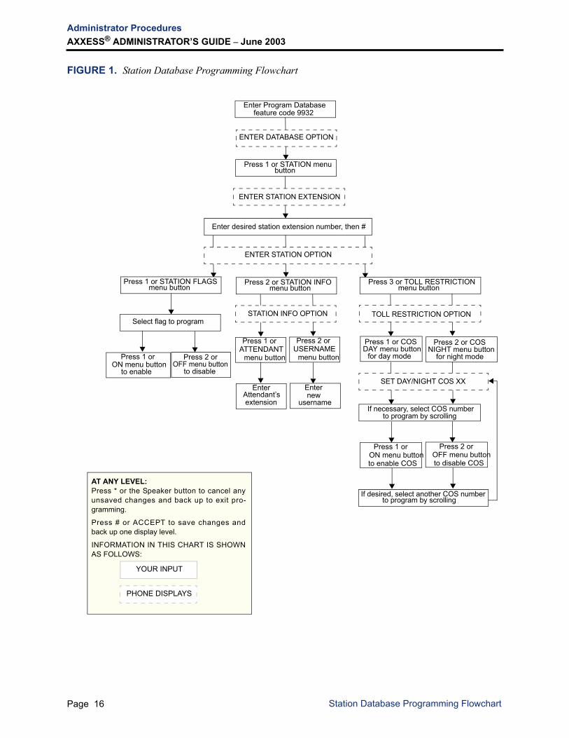
The Station Database Programming process is summarized in the flowchart shown on page 16.See page 59 for a Program Planning Sheet.
NOTE: If necessary, you can press the asterisk ( ) or Speaker button to cancel programmingand discard any unsaved changes, at any time during the following procedure.
TO PROGRAM STATIONS:
1. While on hook, enter the Program Database feature code (9932).
2. If a password is required, the display shows ENTER PASSWORD. Use the dialpad toenter your 1-8 digit password and press . (If you enter an incorrect password or donot press , the display shows INVALID PASSWORD.)
If a password is not required, skip this step.
3. The display shows ENTER DATABASE OPTION. (Display phones also show theoptions: STATION, SYSTEM, and TRUNK.) Press or the STATION menu button.
4. The display shows ENTER STATION EXTENSION. Enter the extension number of thestation to be programmed using one of the following methods. (If you enter an invalidextension number, you hear reorder tones and must try again.)
Enter a complete number: Enter the extension number using your dialpad. When thecircuit information is displayed, press again to continue.
Enter a partial number: Enter a partial extension number, then press , the highend of the Volume button, or the ACCEPT menu button. The display shows the exten-sion number, username and circuit number of the station that most closely matches thepartial extension number. Press or ACCEPT to program the displayed station, orscroll to another station as described below.
Scroll through the numbers: To scroll through the extension number list, press thehigh end of the Volume button or NEXT to scroll forward, or press the low end of theVolume button or PREVIOUS to scroll backward. When the desired extension numberis displayed, press or ACCEPT to continue.
#
#
1
#
#
#
#
Page 13Placing the System in Night Mode

Administrator ProceduresAXXESS® ADMINISTRATOR’S GUIDE – June 2003
5. The display shows ENTER STATION OPTION. Select one of the following:
a. Station Flags: This option allows you to set the Administrator Station, Attendant,and House Phone flags. To select it, press or the STATION FLAGS menu but-ton. There are three flags that can be programmed: Administrator, Attendant, andHouse Phone. (However, you cannot program the Administrator flag for your ownstation or for a single-line station.) To program the flags, do the following:
1. To scroll to the desired flag: Press the high end of the Volume button orNEXT to scroll forward, or press the low end of the Volume button or PRE-VIOUS to scroll backward.
2. To enable or disable a displayed flag: Press or the ON menu button toenable the flag. Or, press or the OFF menu button to disable the flag.
3. To save your programming when all flags are set correctly: Press orACCEPT to save the new flag settings. The display shows DATABASEUPDATED and then returns to the ENTER STATION OPTION prompt.
4. To exit without saving your changes: Press or CANCEL to exit. The dis-play shows NO UPDATE PERFORMED and then returns to the ENTERSTATION OPTION prompt.
b. Station Information: This option allows you to select an attendant for the station orprogram the station’s username. To select it, press or the STATION INFOmenu button. The display shows ENTER STATION INFO OPTION. Select one ofthe following:
1. Attendant: To assign an attendant to serve this station, press or theATTENDANT menu button. The display shows ENTER ATTENDANTEXTENSION. Enter the desired extension number. When the circuit informa-tion is displayed, press again to return to the ENTER STATION INFOOPTION prompt. The display shows DATABASE UPDATED. (Or, to cancelyour entry, press or CANCEL. The display shows NO UPDATE PER-FORMED.)
2. Username: To change the username of the station, press or the USER-NAME menu button. The display shows ENTER USERNAME. Enter the newname as described on page 12. (Or, to cancel your entry, press or CAN-CEL. The display shows NO UPDATE PERFORMED.)
1
1
2
#
2
1
#
2
Page 14 Placing the System in Night Mode

Administrator ProceduresAXXESS® ADMINISTRATOR’S GUIDE – June 2003
c. Toll Restriction: This option allows you to set the station class of service for dayand/or night modes. To select it, press or the TOLL RESTRICTION menu but-ton. Then do the following:
1. The display shows TOLL RESTRICTION OPTION. Press or the COSDAY menu button to program day mode toll restriction. Or, press or theCOS NIGHT menu button to program night mode toll restriction.
2. The display shows SET DAY (or NIGHT) COS XX. If this is not the COSyou wish to program, scroll to the correct COS by pressing the high end of theVolume button or NEXT to scroll forward, or press the low end of the Volumebutton or PREVIOUS to scroll backward. The default COS numbers are asfollows. See page 137.
COS 01 – ARS OnlyCOS 02 – Deny Area/OfficeCOS 03 – Deny OperatorCOS 04 – Deny Toll AccessCOS 05 – Deny InternationalCOS 06 – Deny Equal AccessCOS 07 – Deny Local CallsCOS 08 – Denied NumbersCOS 09 – Allowed Numbers
3. When the correct COS is displayed, press or the ON menu button toenable the toll restriction. Or, press or the OFF menu button to disable it.
4. If desired, repeat steps c2 and c3 to program additional COS toll restrictions.
5. Press or ACCEPT to save the COS programming. The display showsDATABASE UPDATED and then returns to the TOLL RESTRICTIONOPTION prompt.
6. Press again to exit to the ENTER STATION OPTION prompt.
6. When the display shows ENTER STATION OPTION, press again to exit to theENTER STATION EXTENSION prompt. You can then program another station byrepeating these steps or press or ACCEPT once more to exit to the ENTER DATA-BASE OPTION prompt.
7. When finished with all programming, press while the ENTER DATABASEOPTION prompt is displayed. This ends the programming session.
8. If a system reset is required, the display shows ENTER SYS RESET OPTION. Do oneof the following:
— Delayed Reset: Press or the DELAYED menu button to delay the reset. Thedisplay shows DELAYED RESET SCHEDULED. The system will be reset at thepre-programmed time.
— Immediate Reset: Press or the IMMEDIATE menu button to reset the systemnow.
NOTE: A system reset will drop all calls in progress.
3
1
2
1
2
#
#
#
#
#
1
2
Page 15Placing the System in Night Mode
Administrator ProceduresAXXESS® ADMINISTRATOR’S GUIDE – June 2003
FIGURE 1. Station Database Programming Flowchart
Enter Program Databasefeature code 9932
Press 1 or STATION menubutton
ENTER DATABASE OPTION
ENTER STATION EXTENSION
Enter desired station extension number, then #
ENTER STATION OPTION
Press 2 or STATION INFOmenu button
STATION INFO OPTION
Press 3 or TOLL RESTRICTIONmenu button
TOLL RESTRICTION OPTION
Press 1 or STATION FLAGSmenu button
Select flag to program
Press 1 orATTENDANT
menu button
Press 2 orUSERNAME
menu button
Enternew
usernameextension
EnterAttendant’s
Press 1 orON menu button
to enable
Press 2 orOFF menu button
to disable
Press 1 or COSDAY menu button
for day mode
Press 2 or COSNIGHT menu button
for night mode
SET DAY/NIGHT COS XX
If necessary, select COS number
Press 1 orON menu buttonto enable COS
If desired, select another COS number
to program by scrolling
Press 2 orOFF menu buttonto disable COS
to program by scrolling
YOUR INPUT
PHONE DISPLAYS
AT ANY LEVEL:Press * or the Speaker button to cancel anyunsaved changes and back up to exit pro-gramming.
Press # or ACCEPT to save changes andback up one display level.
INFORMATION IN THIS CHART IS SHOWNAS FOLLOWS:
Page 16 Station Database Programming Flowchart

Administrator ProceduresAXXESS® ADMINISTRATOR’S GUIDE – June 2003
System Programming Using an Administrator’s Station
You can use your administrator station to program the following system-wide information:
• Define Do-Not-Disturb messages: The messages for the Do-Not-Disturb feature canbe reprogrammed through an administrator’s station. (See page 230 for informationconcerning their use.) Administrators can delete or change messages 01-20 to any value(up to 16 characters). When the system has a programmed Primary and Secondary Lan-guage, the system has default Do-Not-Disturb messages in both languages. (Availablelanguages are American English, British English, Spanish, and Japanese.) The currentlanguage of the programming phone determines which list is programmed. (Seepage 155 for a description of the Change Language feature.) The Secondary Languagetranslation has the same meaning as the Primary Language message. The default mes-sages are:
When two languages are enabled and DND messages are changed, the programmershould attempt to keep the meanings for the messages in both lists the same. That is, ifthe Primary Language message 02 is changed to “PAGE ME,” a similar message shouldbe programmed for the Secondary Language message 02.
• Select an administrator Database Programming password: Entry to the DatabaseProgramming feature at the administrator stations can be protected using a password. Apassword would prevent unauthorized users from altering the system database.
• Define reminder messages: System reminder messages can be changed using anadministrator’s station. (See page 241 for information about using reminder messages.)The messages can have up to 16 characters each. When Primary and Secondary Lan-guages are enabled, the system has default reminder messages in both languages. Thecurrent language of the programming phone determines which list is programmed. (Seepage 155 for a description of the Change Language feature.) Each Secondary Languagetranslation has the same meaning as the Primary Language message. The default mes-sages are:
01 DO-NOT-DISTURB 11 OUT OF TOWN 'TIL
02 LEAVE A MESSAGE 12 OUT OF OFFICE
03 IN MEETING UNTIL 13 OUT UNTIL
04 IN MEETING 14 WITH A CLIENT
05 ON VACATION 'TIL 15 WITH A GUEST
06 ON VACATION 16 UNAVAILABLE
07 CALL ME AT 17 IN CONFERENCE
08 AT THE DOCTOR 18 AWAY FROM DESK
09 ON A TRIP 19 GONE HOME
10 ON BREAK 20 OUT TO LUNCH
01 MEETING 11 CALL ENGINEERING
02 STAFF MEETING 12 CALL MARKETING
03 SALES MEETING 13 CALL ACCOUNTING
04 CANCEL MEETING 14 CANCEL DND
05 APPOINTMENT 15 CANCEL CALL FWD
06 PLACE CALL 16 TAKE MEDICATION
07 CALL CLIENT 17 MAKE RESERVATION
08 CALL CUSTOMER 18 REVIEW SCHEDULE
09 CALL HOME 19 LUNCH
10 CALL CORPORATE 20 REMINDER
Page 17Station Database Programming Flowchart

Administrator ProceduresAXXESS® ADMINISTRATOR’S GUIDE – June 2003
When two languages are enabled and reminder messages are changed, the programmershould attempt to keep the meanings for the messages in both lists the same. That is, ifthe Primary Language message 02 is changed to “GO TO AIRPORT,” a similar mes-sage should be programmed for the Secondary Language message 02.
• Program new extension numbers for stations: The extension number for any stationcan be changed by an administrator. The new extension number cannot conflict with anexisting number.
• Swap extensions: An extension number can be relocated (swapped) to another station.To swap extensions, the two affected stations must meet the following criteria:
— Both devices must reside on the same node as the administrator performing theswap.
— Both devices must be the same type (i.e., both digital phones or both single-linesets).
— Neither device can be the administrator phone performing the swap.
The System-Wide Database Programming process is summarized in the flowchart shown onpage 22. See page 59 for a Program Planning Sheet.
If necessary, you can press or the Speaker button to cancel programming and discard anyunsaved changes, at any time during the following procedure.
TO PROGRAM THE SYSTEM DATABASE:
NOTE: If you wish to change the Japanese DND or reminder message sets, make sure yourstation is set in Japanese mode. See page 155 for an explanation of the Change Language fea-ture.
1. While on hook, enter the Program Database feature code (9932).
2. If a password is required, the display shows ENTER PASSWORD. Use the dialpad toenter your 1-8 digit password and press . (If you enter an incorrect password, the dis-play shows INVALID PASSWORD.)
If a password is not required, skip this step.
3. The display shows ENTER DATABASE OPTION. (Display phones show the options:STATION, SYSTEM, and TRUNK.) Press or the SYSTEM menu button.
4. The display shows ENTER SYSTEM OPTION. Select one of the following:
a. Do-Not-Disturb Messages: This option allows you to program the DND messagesused by the stations. To select it, press or the DND MESSAGES menu button.Then do the following:
1. The display shows SELECT DND MESSAGE #. Enter a message number orscroll to the desired message. (To scroll to the correct message, press the Vol-ume button or the SCROLL plus NEXT and PREVIOUS menu buttons.)
2. When the display shows the desired DND message, enter the new message asdescribed on page 12.
3. Press or ACCEPT to save the new message. The display shows DATA-BASE UPDATED and then returns to the SELECT DND MESSAGE prompt.(Or, to cancel your entry, press or CANCEL. The display shows NOUPDATE PERFORMED.)
#
2
1
#
Page 18 Station Database Programming Flowchart

Administrator ProceduresAXXESS® ADMINISTRATOR’S GUIDE – June 2003
4. To program another message, scroll to the desired message and repeat thesesteps.
5. Press again to exit to the ENTER SYSTEM OPTION prompt.
b. Password: This option allows you to set a password that limits access to the admin-istrator programming feature. To select it, press or the PASSWORD menu but-ton. Then do the following:
1. The display shows CHANGE PASSWORD TO. Enter a password of up toeight digits, then press . (Or, to erase the password and leave it blank, justpress .)
2. The display shows VERIFY PASSWORD. Enter the password exactly as youdid in the step above, followed by . The display returns to the ENTERSYSTEM OPTION prompt. (If you hear reorder tones and see an error mes-sage, the passwords did not match and you must start over at the CHANGEPASSWORD prompt.)
c. Reminder Messages: This option allows you to program the reminder messagesused by the stations. To select it, press or the REMINDER MSGS menu but-ton. Then do the following:
1. The display shows SELECT REMINDER MSG #. Enter a message number orscroll to the desired message. (To scroll to the correct message, press the Vol-ume button or the SCROLL plus NEXT and PREVIOUS menu buttons.)
2. When the display shows the desired message, enter the new message asdescribed on page 12.
3. Press or ACCEPT to save the new message. The display shows DATA-BASE UPDATED and then returns to the SELECT REMINDER MSGprompt. (Or, to cancel your entry, press or CANCEL. The display showsNO UPDATE PERFORMED.)
4. To program another message, scroll to the desired message and repeat thesesteps.
5. Press again to exit to the ENTER SYSTEM OPTION prompt.
d. Station Extensions: This option allows you to assign new extension numbers to sta-tions. To select it, press or the STN EXTENSION menu button.
If programming a station:
1. Press or CHANGE EXT. The display shows ENTER STATION EXTEN-SION. Enter the extension number of the station to be programmed using oneof the following methods. (If you enter an invalid extension number, you hearreorder tones and must try again.)
Enter a complete number: Enter the extension number using your dialpad.When a valid number is entered, the circuit information is displayed. Press again to continue.
Enter a partial number: Enter a partial extension number, then press , thehigh end of the Volume button, or the ACCEPT menu button. The displayshows the extension number, username and circuit number of the station thatmost closely matches the partial extension number. Press or ACCEPT toprogram the displayed station, or scroll to another station as described below.
#
2
#
#
#
3
#
#
4
1
#
#
#
Page 19Station Database Programming Flowchart

Administrator ProceduresAXXESS® ADMINISTRATOR’S GUIDE – June 2003
Scroll through the numbers: To scroll through the extension number list,press the high end of the Volume button or the NEXT menu button to scrollforward, or press the low end of the Volume button or the PREVIOUS menubutton to scroll backward. When the desired extension number is displayed,press or ACCEPT to continue.
2. The display shows CHANGE X (number) TO EXTENSION. Enter the newextension number for the station. If you enter an invalid number, you hearreorder tones and must try again. If you entered an extension number that isalready assigned, the display shows CONFLICTING EXTENSION and youhear reorder tones. When the display returns to ENTER STATION EXTEN-SION, you must start over and select a new extension number.
3. Press or ACCEPT to exit to the ENTER STATION EXTENSION prompt.The display shows UPDATING DATABASE for four seconds and thenDATABASE UPDATED. (Or, to cancel your entry, press or CANCEL.The display shows NO UPDATE PERFORMED.)
NOTE: Although the system begins to update the database when you press orACCEPT, it may take longer than the four-second display to change the extension inthe system – especially in a large or busy system.
4. Press or ACCEPT again to exit to the ENTER SYSTEM OPTIONprompt. (If an extension number is displayed, press to exit, instead of or ACCEPT.)
If swapping stations:
1. Press or SWAP EXTS. The display shows ENTER STATION EXTEN-SION. Enter the first extension number to be swapped using one of the fol-lowing methods. (If you enter an invalid extension number, you hear reordertones and must try again.)
Enter a complete number: Enter the extension number using your dialpad.When a valid number is entered, the circuit information is displayed. Press or ACCEPT to continue.
Enter a partial number: Enter a partial extension number, then press the button, the high end of the Volume button, or the ACCEPT menu button. Thedisplay shows the extension number, user name and circuit number of the sta-tion that most closely matches the partial extension number. Press orACCEPT to continue, or scroll to another station as described below.
Scroll through the numbers: To scroll through the extension number list,press the high end of the Volume button or the NEXT menu button to scrollforward, or press the low end of the Volume button or the PREVIOUS menubutton to scroll backward. When the desired extension number is displayed,press or ACCEPT to continue.
NOTE: If the feature times out while entering an extension number, the displaysshows INCOMPLETE EXTENSION.
2. The display shows SWAP (extension) WITH EXTENSION. Enter the secondextension number to be swapped using the same methods previouslydescribed. The display shows DATABASE UPDATED.
#
#
#
#
#
2
#
#
#
#
Page 20 Station Database Programming Flowchart

Administrator ProceduresAXXESS® ADMINISTRATOR’S GUIDE – June 2003
NOTE: If you cancel or terminate the feature without entering the second extensionnumber, the system discards any changes that have not yet been saved, and thedisplay shows NO UPDATE PERFORMED. If the entered extension is the adminis-trator station performing the swap, the same extension number as the target station,or the wrong device type, the display shows CONFLICTING EXTENSION.
5. When the display shows ENTER SYSTEM OPTION, press again to exit to theENTER DATABASE OPTION prompt.
6. When finished with all programming, press while the ENTER DATABASEOPTION prompt is displayed. This ends the programming session.
7. If a system reset is required, the display shows ENTER SYS RESET OPTION. Do oneof the following:
— Delayed Reset: Press or the DELAYED menu button to delay the reset. Thedisplay shows DELAYED RESET SCHEDULED. The system will be reset at thepre-programmed time.
— Immediate Reset: Press or the IMMEDIATE menu button to reset the systemnow.
NOTE: A system reset will drop all calls in progress.
#
#
1
2
Page 21Station Database Programming Flowchart

Administrator ProceduresAXXESS® ADMINISTRATOR’S GUIDE – June 2003
FIGURE 2. System Database Programming Flowchart
Enter Program Databasefeature code 9932
Press 2 or SYSTEM menu button
ENTER DATABASE OPTION
Press 2 orPASSWORDmenu button
Enter the newmessage using alpha
or numeric mode
ENTER SYSTEM OPTION
Enter messagenumber or selectDND message to
Press 1 orDND MESSAGES
menu button
Press 4 orSTN EXTENSIONS
menu button
Press 1 orCHANGE EXT
menu button
SELECT DND
If desired, selectanother message
(DND message)SCROLL OR EDIT
Enter the new
CHANGE
VERIFY
Enter the newmessage using alpha
or numeric mode
Enter messagenumber or select
message to program
SELECT
If desired, selectanother message
(Reminder message)SCROLL OR EDIT
Enter the newextension number
and press #
Enter the extension
ENTER STATION
CHANGE (number)SCROLL OR EDIT
Enter 0-8 digitpassword and
password again
EXTENSION
number of the stationto be changed
YOUR INPUT
PHONE DISPLAYS
AT ANY LEVEL:Press * or the Speaker button to cancel any un-saved changes and back up to exit program-ming.
Press # or ACCEPT to save changes and backup one display level.
INFORMATION IN THIS CHART IS SHOWNAS FOLLOWS:
MESSAGE
program by scrolling
and press #
to program
PASSWORD
press #
PASSWORD
and press #
REMINDER MSG
by scrolling
and press #
to program for the station
Enter the extensionnumber of the second
and press #
Enter the extension
ENTER STATION
SWAP (extension)WITH EXTENSION
EXTENSION
number of the firststation to be swapped
station to be swapped
Press 2 orSWAP EXTS
menu button
Press 3 orREMINDER MSGS
menu button
and press #
Page 22 System Database Programming Flowchart

Administrator ProceduresAXXESS® ADMINISTRATOR’S GUIDE – June 2003
Trunk Programming Using an Administrator’s Station
The trunk information that can be programmed by an administrator station includes the follow-ing:
Individual trunks:
• Answer supervision type: Answer supervision determines whether the system shouldconsider a call valid when it receives polarity reversal from the central office or wait forthe Valid Call timer to expire. Any outside call put on hold becomes valid immediately,regardless of Answer Supervision or Valid Call timer status. There are three optionsavailable under answer supervision type:— Polarity Reversal: A loop reversal must be received to consider the call valid.
When the first loop reversal is received, the call is made valid immediately, and theInter-Tel phone display will begin call cost. When a second loop reversal isreceived, the system will terminate the call.
NOTE: If a second loop reversal is not received, the system will not terminate thecall unless the inside party hangs up or loss-of-loop is received from the Telephonecompany.
— Valid Call Timer: After the Valid Call Timer expires, the call is validated. Allpolarity reversals received before and after the Valid Call Timer are ignored.
— Valid Call Timer with Polarity Reversal: If a loop reversal is received before theValid Call Timer expires, the call will be made valid immediately, and the Inter-Telphone display will begin call cost. When a second loop reversal is received, thesystem will terminate the call. If a loop reversal is not received before the ValidCall Timer expires, the call will be made valid by the timer. If a loop reversal isreceived after the timer expires, the loop reversal is ignored, but the call cost isreset. If a second loop reversal is then received, the system will terminate the call.
NOTE: If a second loop reversal is not received, the system will not terminate thecall unless the inside party hangs up or loss-of-loop is received from the Telephonecompany.
• Caller ID: When selected, the Caller ID option indicates that the associated trunk willprovide caller identification signals. This cannot be programmed unless the AdvancedCO Interfaces premium feature is included in your software license.
• Hybrid balance: Hybrid balance can be set to Normal or Short to allow the installer toadjust the hybrid impedance of the trunk based on local central office conditions.— Short: The short balance is used when trunks are supplied by other equipment
located within the same building, using private, copper wire termination (e.g., anOPX supplied by another PBX that does not use the public network) or when thesite is located close to the central office.
— Normal: The normal balance can be used by most trunks.
• DTMF or dial-pulse signaling: Trunks can be set for DTMF or dial pulse signals.
• Trunk group assignment: Trunks can be assigned to trunk groups on an individualbasis.
• Busy trunk: This feature allows the administrator to temporarily remove a trunk fromservice. While the trunk is out of service, it cannot be used for placing outgoing calls.However, incoming calls on analog trunks will ring in and can be answered. Incomingcalls on ISDN trunks cannot be answered. The trunk will remain out of service until theTrunk Busy Out timer expires or the administrator places the trunk back in service.
Page 23System Database Programming Flowchart

Administrator ProceduresAXXESS® ADMINISTRATOR’S GUIDE – June 2003
Trunk groups:
• Day/Night Answer Access: You can program separate lists for stations with allowed-answer access in day and night modes.
• Day/Night Ring-In: You can program separate lists of stations with ring-in for day andnight modes.
• Change Toll Restrictions: You can program toll restriction classes of service for thetrunk groups. Classes of service are described in detail on page 137.
• Trunk List: Each trunk group has a programmed list of individual trunks.
The Trunk Database Programming process is summarized in the flowchart shown on page 28.See page 59 for a Program Planning Sheet.
NOTE: If necessary, you can press the asterisk ( ) or Speaker button to cancel programmingand discard any unsaved changes at any time during the following procedure.
Entering extension numbers:
When the procedure asks you to enter a station, trunk, or trunk group extension number, youcan use any of the following methods (If you enter an invalid extension number, you hear reor-der tones and must try again.)
• Enter a complete number: Enter the extension number using your dialpad. When thecircuit information is displayed, press again to continue.
• Enter a partial number: Enter a partial extension number then press , the high endof the Volume button, or the menu button. The display shows the extension number,username and circuit number of the station, trunk, or trunk group that most closelymatches the partial extension number. Press or ACCEPT to accept the displayedextension, or scroll to another station as described below.
• Scroll through the numbers: To scroll through the extension number list, press thehigh end of the Volume button or the NEXT menu button to scroll forward, or press thelow end of the Volume button or the PREVIOUS menu button to scroll backward.When the desired extension number is displayed, press or ACCEPT to continue.
TO PROGRAM TRUNK INFORMATION:
1. While on hook, enter the Program Database feature code (9932).
2. If a password is required, the display shows ENTER PASSWORD. Use the dialpad toenter your 1-8 digit password and press . (If you enter an incorrect password, the dis-play shows INVALID PASSWORD.)
If a password is not required, skip this step.
3. The display shows ENTER DATABASE OPTION. (Executive Display, ProfessionalDisplay and Model 8560 Phones also show the options: STATION, SYSTEM, andTRUNK.) Press or the TRUNK menu button. The display shows ENTER TRUNKOPTION.
#
#
#
#
#
#
3
Page 24 System Database Programming Flowchart

Administrator ProceduresAXXESS® ADMINISTRATOR’S GUIDE – June 2003
4. To Program an Individual Trunk: Press or the INDIVIDUAL TRUNK menu but-ton. Then program trunk options as follows:
a. The display shows ENTER TRUNK EXTENSION. Enter the extension number ofthe trunk to be programmed using one of the methods described on page 24.
b. The display shows INDIVIDUAL TRUNK OPTION. Enter one of the followingoptions. To view the last two options on a display phone, press the arrow (<< or>>) menu button at the bottom of the display.
Answer Supervision: To program the answer supervision for the trunk, press orthe ANS SUPERVISION menu button. When the display shows ANS SUPERVI-SION OPTION, press or the POLARITY REVERSE menu button for thepolarity-reversal supervision type. Or, press or the VALID CALL menu buttonfor Valid Call timer supervision. Or, press or the VALID + POLARITY menubutton for Valid Call timer with Polarity Reversal supervision. Then press orACCEPT to continue.
Caller ID: To enable or disable Caller ID, press or the CALLER ID menu but-ton. When the display shows SET CALLER ID, press or ON to enable the fea-ture, or press or OFF to disable it. Then press or ACCEPT to continue.
Hybrid Balance: To set the hybrid balance of the trunk to normal or short, press or the HYBRID BALANCE menu button. When the display shows HYBRIDBALANCE OPTION, press or the NORMAL menu button, or press or theSHORT menu button. Then press or ACCEPT to continue.
DTMF/Dial-Pulse Signaling: To set the trunk for DTMF or dial-pulse signaling,press or the SIGNALING menu button. When the display shows ENTER SIG-NALING OPTION, press or the DTMF menu button, or press or thePULSE menu button. Then press or ACCEPT to continue.
Trunk Group Number: To assign the trunk to a trunk group, press or theTRUNK GROUP menu button. When the display shows ENTER TRUNK GRPEXTENSION, enter the desired trunk group number using one of the methodsdescribed on page 24.
Busy Trunk: To temporarily remove the trunk from service, press or the BUSYTRUNK menu button. When the display shows MARK TRUNK BUSY, press or the ON menu button, or press or the OFF menu button. Then press orACCEPT to continue.
c. To exit, press or ACCEPT to move backward through the prompts until youreach the ENTER DATABASE OPTION prompt.
5. To Program A Trunk Group: Press or the TRUNK GROUP menu button. Thenprogram the trunk group, as follows:
a. The display shows ENTER TRUNK GRP EXTENSION. Enter the extension num-ber of the trunk group to be programmed using one of the methods described onpage 24.
b. The display shows ENTER TRUNK GROUP OPTION. Select one of the followingoptions. To view the last three options on a display phone, press the arrow (<< or>>) menu button at the bottom of the display.
1
1
1
2
3
#
2
1
2 #
3
1 2
#
4
1 2
#
5
6
1
2 #
#
2
Page 25System Database Programming Flowchart

Administrator ProceduresAXXESS® ADMINISTRATOR’S GUIDE – June 2003
Answer Access For Day Or Night Mode: To program the station(s) that will haveanswer access for this trunk group for day mode, press or the ANS-ACCESSDAY menu button. To program for night mode, press or the ANS-ACCESSNIGHT menu button. When the display shows ENTER STATION EXTENSION,do the following:
1. Enter a station extension using one of the methods described on page 24.
2. The display shows the extension number and a Yes/No prompt. Press orthe YES menu button, followed by , to include the station in the list. Or,press or the NO menu button, followed by , to exclude the station fromthe list.
3. When the display returns to ENTER STATION EXTENSION, select anotherextension number. Or, if finished programming the station list, press orACCEPT to continue.
Ring-In For Day Or Night Mode: To program the station that will have ring in forthis trunk group for day mode, press or the RING-IN DAY menu button. Toprogram for night mode, press or the RING-IN NIGHT menu button. When thedisplay shows ENTER STATION EXTENSION, enter stations into the list one at atime as described above for Answer Access.
Toll Restriction: To program the toll restrictions for the trunk group, press orthe TOLL RESTRICTION menu button. When the display shows TOLLRESTRICTION OPTION, press the numbers that correspond to the toll restrictionsyou wish to program, as follows:
1. COS for day or night mode: To program the toll restriction class of service forday mode, press or the COS DAY menu button. To program class of ser-vice for night mode, press or the COS NIGHT menu button. The displayshows SET DAY (or NIGHT) COS XX. If this is not the COS you wish toprogram, scroll to the correct COS by pressing the high end of the Volumebutton or the NEXT menu button to scroll forward, or press the low end of theVolume button or the PREVIOUS menu button to scroll backward. Thedefault COS numbers are listed below. (See page 137 for definitions. COS 01is not used for trunks.) When the correct COS is displayed, press or theON menu button to enable the toll restriction. Or, press or the OFF menubutton to disable it. If desired, repeat this step to program additional COS tollrestrictions. Then press or ACCEPT to continue.
COS 02 – Deny Area/OfficeCOS 03 – Deny OperatorCOS 04 – Deny Toll AccessCOS 05 – Deny InternationalCOS 06 – Deny Equal AccessCOS 07 – Deny Local CallsCOS 08 – Denied NumbersCOS 09 – Allowed Numbers
2. Exempt from ARS: To program the Exempt from ARS option, press or theEXEMPT FROM ARS menu button. When the display shows EXEMPTFROM ARS, press or the YES menu button to enable the option. Or,press or the NO menu button to disable it. Then press or ACCEPT tocontinue.
1
2
1
#
2 #
#
3
4
5
1
2
1
2
#
3
1
2 #
Page 26 System Database Programming Flowchart

Administrator ProceduresAXXESS® ADMINISTRATOR’S GUIDE – June 2003
3. Subject to toll restriction: To program the trunk group Subject to Toll Restric-tion option, press or the SUBJECT TO TOLL menu button. When thedisplay shows SUBJECT TO TOLL, press or the YES menu button toenable the option. Or, press or the NO menu button to disable it. Thenpress or ACCEPT to continue.
Trunk List: To program the list of trunks for the trunk group, press or theTRUNK LIST menu button. When the display shows ENTER TRUNK EXTEN-SION, enter trunks into the list as follows:
1. Enter a trunk extension using one of the methods described on page 24. 2. The display shows the extension number and a Yes/No prompt. Press or
the YES menu button, followed by , to include the trunk in the list. Or,press or the NO menu button, followed by , to exclude the trunk fromthe list.
3. When the display returns to ENTER TRUNK EXTENSION, select anotherextension number. Or, if finished programming the trunk list, press orACCEPT to continue.
c. To exit, press or ACCEPT to move backward through the prompts until youreach the ENTER DATABASE OPTION prompt.
6. When finished with all programming, press while the ENTER DATABASEOPTION prompt is displayed. This ends the programming session.
7. If a system reset is required, the display shows ENTER SYS RESET OPTION. Do oneof the following:
• Delayed Reset: Press or the DELAYED menu button to delay the reset. Thedisplay shows DELAYED RESET SCHEDULED. The system will be reset at thepre-programmed time.
• Immediate Reset: Press or the IMMEDIATE menu button to reset the systemnow.
NOTE: A system reset will drop all calls in progress.
4
1
2
#
6
1
#
2 #
#
#
#
1
2
Page 27System Database Programming Flowchart

Administrator ProceduresAXXESS® ADMINISTRATOR’S GUIDE – June 2003
FIGURE 3. Trunk Database Programming Flowchart
Enter Program Databasefeature code 9932
Press 3 or TRUNK menu button
ENTER DATABASE OPTION
ENTER TRUNK OPTION
Press 1 or INDIVIDUAL TRUNK
ENTER TRUNK EXTENSION
YOUR INPUT
PHONE DISPLAYS
AT ANY LEVEL:Press * or the Speaker but-ton to cancel any unsavedchanges and back up toexit programming.
Press # or ACCEPT tosave changes and back upone display level.
INFORMATION IN THISCHART IS SHOWN ASFOLLOWS:
menu buttonPress 2 or TRUNK GROUP
ENTER TRUNK GRP EXTENSION
menu button
SEE NEXT PAGEEnter desired trunkextension number
ANS SUPERVISION OPTION
Press 1 or POLARITYREVERSE menu button
Press 2 or VALIDCALL menu button
SET CALLER ID
Press 1 or ONmenu button
Press 2 or OFFmenu button
HYBRID BALANCE OPTION
Press 1 or NORMALmenu button
Press 2 or SHORTmenu button
ENTER SIGNALING OPTION
Press 1 or DTMFmenu button
Press 2 or PULSEmenu button
ENTER TRUNK GRP EXTENSION
MARK TRUNK BUSY
Press 1 orANSWER SUPERVISION
menu button
Press 2 orCALLER IDmenu button
Press 3 orHYBRID BALANCE
menu button
Press 4 orSIGNALING
menu button
TRUNK GROUPmenu button
INDIVIDUAL TRUNK OPTION
Press 6 orTRUNK BUSY
menu button
Enter the trunk group number
Press 1 or ONmenu button
Press 2 or OFFmenu button
Press 5 or
Press 3 or VALID +POLARITY menu button
Page 28 Trunk Database Programming Flowchart

Administrator ProceduresAXXESS® ADMINISTRATOR’S GUIDE – June 2003
FIGURE 3. Trunk Database Programming Flowchart (Continued)
Press 1 orANS ACCESS DAY
menu button
TOLL RESTRICTIONmenu button
Press 6 orTRUNK LIST
menu button
CONTINUED FROM PREVIOUS PAGE
Enter the number of the trunk groupto be programmed
Press 1 or YES Press 2 or NO
Press 2 orANS ACCESS NIGHT
menu button
Press 3 orRING-IN DAY
menu button
Press 4 orRING-IN NIGHT
menu button
TOLL RESTRICTION OPTION
Press 1 or COSDAY menu button
Press 2 or COSNIGHT menu button
Press 3 or EXEMPTFROM ARS menu button
Press 4 or SUBJECTTO TOLL menu button
SET DAY/NIGHT COS XX
If necessary, select COS numberto program by scrolling
Press 1 or ON Press 2 or OFF
EXEMPT FROM ARS
Press 1 or YES Press 2 or NO
SUBJECT TO TOLL
Press 1 or YES Press 2 or NO
ENTER TRUNK EXTENSION
Enter the desired trunk number
Press 1 or YES Press 2 or NO
(Extension number) YES/NO
Press 5 or
ENTER STATION EXTENSION
Enter the desired extension number
(Extension number) YES/NO
menu button menu button
menu button menu button menu button menu button
menu button menu button
menu button menu button
TRUNK GROUP OPTION
Page 29Trunk Database Programming Flowchart

Administrator ProceduresAXXESS® ADMINISTRATOR’S GUIDE – June 2003
PROGRAMMING SYSTEM SPEED-DIAL NUMBERSSystem speed-dial numbers and names can be programmed by the installer or at any adminis-trator station.
The system speed-dial numbers can contain up to 48 digits each and can include hookflashesand/or pauses for dialing a series of numbers. For example, the speed-dial number can containan SCC local number, a pause, an access code, and the telephone number. For using PBXtrunks, the other system’s trunk access codes, followed by a pause, may be included in speed-dial numbers. The lengths of the hookflash and the pause are determined by the programmableCO Hookflash and Pause Digit timers.
To program system speed-dial numbers, use one of the following methods:
• Use the dialpad to manually dial the number. If you make a mistake, press tobackspace.
• Press to enter the last number dialed or saved at the station (up to 48 digits).
• Press one of the speed-dial buttons on the Inter-Tel phone to enter the outside telephonenumber (up to 16 digits) programmed under that button.
Speed-dial names can contain up to 16 characters. To program speed-dial names, dialpad but-tons are used to enter the desired letters, numbers, and punctuation in English/Spanish, or Japa-nese (Katakana). When programming speed-dial names, you can press or USEALPHA MODE/USE NUMERIC MODE menu button to switch back and forth betweenalphanumeric and numeric mode.
• In numeric mode, the dialpad buttons are used to enter numbers 0-9, the pound ( )button is used for entering a hyphen (-), and the asterisk ( ) button is used for enteringa colon (:). For example, 1 00 would enter “1:00” in numeric mode.
• In alphanumeric mode, dialpad buttons are used to enter the desired letters, numbers,and punctuation. The number of times a button is pressed determines which character isentered. For example, 533266 would enter “JEAN.” When adjoining characters arelocated under the same button, press to advance to the next character. Forexample, 66 6667776 would enter “NORM.” Refer to the chart on the follow-ing page to program information in alphanumeric mode. (Note that letters correspond tothe letters printed on the dialpad buttons.) The Japanese characters will be availableonly if the Multilingual Support premium feature is included in your software license,and Japanese is set as the Primary or Secondary Language.
MUTE
REDIAL
MSG
#
FWDFWD
Page 30 Programming System Speed-Dial Numbers

Administrator ProceduresAXXESS® ADMINISTRATOR’S GUIDE – June 2003
* The character available depends on the software version.
**The Japanese characters are only available if the Multilingual feature is enabled and Japaneseis installed as the secondary language.
TO PROGRAM OR CHANGE SYSTEM SPEED-DIAL NUMBERS AND NAMES:
NOTE: If you make a mistake, use the button to backspace. Or, press or CANCELat any time to cancel the operation (the name and number in memory remains unchanged andthe display shows FEATURE CANCELED); then start over.
1. While on hook, enter the Program System Speed-Dial feature code (9801). Displayphones show PROGRAM SYS SPD # (000-999).
2. Enter the speed-dial location code (000-999). The display shows ENTER NAME: (cur-rent name). If you do not continue to the next step, the display times out after the LongInterdigit timer expires and you must start over.
3. To change or program the name: Enter the desired name for the speed-dial numberusing your dialpad as described on page 30, then press or ACCEPT. Refer to thechart on the previous page. If you make a mistake, use the button to back up anderase existing characters or the CLEAR button to erase the whole entry.
To erase the current name and leave it blank: Press CLEAR or press repeatedly until the name is erased. Then press or ACCEPT.
To leave the name the same: Press or ACCEPT.
4. When the display shows ENTER NUMBER, enter the number (up to 48 digits) to bestored using the dialpad, one of the speed-dial buttons, or the button. If neces-sary, use the button to back up and erase existing numbers. (Display phonesshow the number as it is entered.) To include *, #, pause, or hookflash in the number,press the Special button once for an asterisk (*), twice for a pound (#), three times for ahookflash (F), or four times for a pause (P). Executive Display, Professional Display orModel 8560 Phone users can press the , , FLASH, or PAUSE menu buttons toenter special characters. You cannot exceed 48 digits.
5. Press or ACCEPT to save the number. You hear a single progress tone when thenumber is accepted. Your display shows SYS SPD BIN #XXX UPDATED.
NUMBER OF TIMES BUTTON IS PRESSEDBUTTON 1 2 3 4 5 6 7 8 9 10 11
ENGLISH/SPANISH CHARACTERS KATAKANA CHARACTERS**
1 - & ( ) 1 A I U E O a2 A B C ' 2 KA KI KU KE KO i3 D E F ! 3 SA SHI SU SE SO u4 G H I * 4 TA CHI TSU TE TO e5 J K L / or #* 5 NA NI NU NE NO o6 M N O Ñ or /* 6 HA HI FU HE HO tsu7 P Q R S 7 MA MI MU ME MO ya8 T U V ? 8 YA YU YO . , yu9 W X Y Z 9 RA RI RU RE RO yo0 @ : . , 0 WA WO N pa ba long
MUTE
#
MUTE
MUTE
#
#
REDIAL
MUTE
#
#
Page 31Programming System Speed-Dial Numbers

Administrator ProceduresAXXESS® ADMINISTRATOR’S GUIDE – June 2003
TO ERASE SYSTEM SPEED-DIAL NAMES OR NUMBERS:
1. While on hook, enter the Program System Speed-Dial feature code (9801). Displayphones show PROGRAM SYS SPD # (000-999).
2. Enter the speed-dial location code (000-999). The display shows ENTER NAME: (cur-rent name).
3. You may erase the name and/or number:
To erase the name: Press repeatedly until the name is erased or pressCLEAR.
To erase the number: Press or ACCEPT to display the ENTER NUMBERprompt, then press repeatedly until the number is erased or press CLEAR.
4. Press or ACCEPT to exit. You hear a single progress tone when accepted. Your dis-play shows SYS SPD BIN #XXX UPDATED.
SYSTEM AND NETWORK ALARM REPORTING
To allow one administrator to monitor multiple nodes, the system provides both system alarmsand network-wide alarms.
System Alarms
The system’s Alarm Reporting feature detects equipment failures. If there is a system failurethat affects service, a major alarm is displayed at all affected phones. If all Inter-Tel phones inthe system are inoperative, any alarm messages are sent to the system’s primary serial port (onthe CPU).
When a minor equipment failure occurs, a minor alarm is generated and appears on the pri-mary attendant’s display and, if enabled, at administrators’ stations. If enabled in the MessagePrint programming, the alarm also appears in the error/message report.
Alarms 1-99 indicate problems that can be corrected without calling service personnel. Alarms100-199 (telephone system) and 200-299 (voice mail) require attention from service personnel.Note that when a voice mail alarm is in effect, the telephone system may be functioning prop-erly, but the Voice Processor may be inoperative.
Network Alarms
Each node has two flags which determine whether the node broadcasts or receives network-wide alarms.
• The Send Network Alarms flag determines whether a node will broadcast alarms thatoccur on that node to the rest of the network.
• The Receive Network Alarms flag determines whether the node will receive and dis-play alarms sent by other nodes in the network.
To differentiate between network-wide and local alarms, network-wide alarms appear onadministrator phones preceded by “NET ALARM,” and local system alarms are preceded with“SYS ALARM.”
On remote nodes, network-wide alarms will indicate the name of the node on which the alarmoccurred. The node name is obtained from the username.
MUTE
#
MUTE
#
Page 32 Programming System Speed-Dial Numbers

Administrator ProceduresAXXESS® ADMINISTRATOR’S GUIDE – June 2003
An administrator can clear a network-wide alarm on the local node only or on every node inthe network.
• Clear Network Alarm (9851): This feature code clears network-wide alarms on everynode in the network, but will not affect system alarms. The Clear Network Alarm fea-ture code may be entered on any node in the network, but the Send Network Alarmsflag must be set for the administrator to clear alarms on other nodes in the network.
• Clear System Alarm (9850): This feature code clears all local and network-wide sys-tem alarm displays on your node.
Network-wide alarms will override system alarms on an administrator’s phone display.
TO RESPOND TO A MINOR ALARM FROM ANY ALARM DISPLAY STATION:
1. When a minor alarm indication appears, write down the alarm information.
2. While on hook, clear the alarm by entering the Clear System Alarm feature code (9850)or the Clear Network Alarm feature code (9851). The display shows SYSTEM (orNETWORK) ALARM CLEARED.
3. Take action on the alarm as follows:
• #10 XXXXX OFF-HOOK: A station remained off hook and inactive until the Inac-tivity Alarm timer expired. The display and the SMDR indicate which station is offhook. The station’s button on DSS/BLF Units and on other stations’ speed-dial but-tons flutters continuously. Locate the station and replace the handset in the cradle.The station’s display shows STATION OFF HOOK.
NOTE: Calls being transmitted over the secondary voice path are not affected or inter-rupted by an off-hook alarm condition.
• #11 XXXXX EMERGENCY: A user has dialed the Emergency Call feature code(911) and the system has selected a trunk and dialed the programmed emergencynumber.
• #12-13 & 20 CHECK PRINTER: The printer is not functioning properly. Checkthat the cable and the power cord are connected and that it has paper and ribbon.
• #14 SET DATE/TIME: The system real-time clock has not been initialized or hasbeen corrupted. Set the system time and date as described on page 9.
• #21 V-MAIL 80% FULL/#22 V-MAIL 100% FULL: The voice mail disk space iseither 80% or completely full. If it reaches 100%, voice mail cannot accept anymessages until disk space is made available.
• #23 SMDR 80% FULL/#24 SMDR 100% FULL: The SMDR disk space is either80% or completely full. If it reaches 100% before the SMDR information iscleared, no further SMDR recording will be possible.
• #100-199 & 200-299 CALL TECHNICIAN: These alarms indicate that an equip-ment failure has occurred that requires the attention of service personnel. Whencalling for service, be prepared to provide them with the alarm information as wellas what was taking place when the alarm occurred, if anything.
A major alarm message, MAJOR ALARM, appears on all display phones in the event of a sys-tem-wide failure. If the major alarm appears on a group of phones, the associated Keyset Cardmay have failed. The warning might also appear on a single phone if the phone or its cablingmay be defective. Because they indicate that all or part of the system is inoperative, majoralarms require immediate attention from service personnel.
Page 33Programming System Speed-Dial Numbers
Administrator ProceduresAXXESS® ADMINISTRATOR’S GUIDE – June 2003
FREEZING/UNFREEZING THE SYSTEM HISTORY
When certain system failures occur, service personnel might request a “system history freeze.”This allows them access to the system database so that they can analyze system activity for thetime period preceding the alarm.
TO FREEZE OR UNFREEZE SYSTEM HISTORY:
NOTE: Do not perform this procedure unless directed to do so by service personnel.
1. While on hook, enter the Diagnostics Mode feature code (9900) to turn on diagnosticsmode. The display shows DIAGNOSTICS ON.
2. Enter the Freeze System History feature code (9993) or Unfreeze System History fea-ture code (9998). The display shows HISTORY FROZEN (or UNFROZEN). If youattempt change the state of the system history to its current status, the display showsHISTORY ALREADY FROZEN (or UNFROZEN).
3. Enter the Diagnostics Mode feature code (9900) to turn off diagnostics mode. The dis-play shows DIAGNOSTICS OFF.
FREEZING/UNFREEZING THE NETWORK HISTORY
Administrators can freeze or unfreeze the fault history for any node in the network. Servicepersonnel can then pull the information from each node for troubleshooting purposes. Nodesare assigned to freeze zones by the database programmer to allow selective freezes. Theadministrator must know which zone to freeze/unfreeze and then enter the freeze feature codefollowed by the zone number.
A node can be in more than one freeze zone. If the administrator freezes a zone that contains anode that is already frozen, the display will show “SOME NODES ALREADY FROZEN” andthe node will remain frozen. If the administrator unfreezes a zone with unfrozen nodes in it, thedisplay shows “SOME NODES ALREADY UNFROZEN.” To determine the individual freezestatus of the nodes, check the message print output.
NOTE: Do not perform this procedure unless directed to do so by service personnel.
TO FREEZE OR UNFREEZE NETWORK HISTORY:
1. While on hook, enter the Diagnostics Mode feature code (9900) to turn on diagnosticsmode. The display shows DIAGNOSTICS ON.
2. Enter the Network Freeze Zone System Histories feature code (9939) or NetworkUnfreeze Zone System Histories feature code (9989). Display shows SELECT FRZZONE (0-9) #.
3. Enter the number of the zone you wish to freeze or unfreeze. The display showsFREEZE ZONE XX IS FROZEN (or UNFROZEN). If you attempt change the state ofthe system history to its current status, the display shows FREEZE ZONE XXALREADY FROZEN (or UNFROZEN).
4. Enter the Diagnostics Mode feature code (9900) to turn off diagnostics mode. The dis-play shows DIAGNOSTICS OFF.
Page 34 Freezing/Unfreezing the System History

Administrator ProceduresAXXESS® ADMINISTRATOR’S GUIDE – June 2003
SEIZING A DEVICE
For troubleshooting purposes, the Seize Device feature code allows an administrator to enablediagnostics mode and then seize a specific trunk or extension by entering the board, circuit,and device number.
The Seize Device is affected by trunk restriction. The administrator’s station must have outgo-ing access permission for the trunk to seize it. Toll restriction is applied to any calls placedafter the seizure of the trunk.
TO SEIZE A DEVICE:
1. While on hook, enter the Diagnostics Mode feature code (9900) to turn on diagnosticsmode. The display shows DIAGNOSTICS ON.
2. Press the Special button and enter the Seize Device feature code (9973). The displayshows ENTER BOARD.
3. Enter the board number on which the device to be seized is located (if you enter a singledigit, press after the digit to continue). (If you enter an invalid board number, thedisplay shows INVALID BOARD NUMBER.) Do not enter the CPU board number (0).The display shows ENTER PORT.
4. Enter the port (circuit) number of the device to be seized (if you enter a single digit,press after the digit to continue). Valid numbers depend on the type of board. (If youenter an invalid board number, the display shows INVALID BOARD NUMBER.)
If there is only one device on the selected port, the selected device is seized as if theuser had directly entered the extension or trunk number.
If there is more than one device on the selected port, the display shows ENTERDEVICE. Enter the number of the device to be seized. Valid numbers depend on thetype of devices installed. (If you enter an invalid board number, the display showsINVALID BOARD NUMBER.) When the device has been selected, it is seized as ifthe user had directly entered the extension or trunk access number.
5. Enter the Diagnostics Mode feature code (9900) to turn off diagnostics mode. The dis-play shows DIAGNOSTICS OFF.
For example, if the administrator wanted to seize the T1 trunk on the tenth circuit of the T1C incard slot 3 (circuit 3.10.0), the entries would be as follows:
ENTER BOARD: 3
ENTER PORT: 10
(Device number not required.)
However, to select the first single-line device connected to the second circuit of the KSC incard slot 5 (circuit 5.2.1), the entries would be as follows:
ENTER BOARD: 5
ENTER PORT: 2
ENTER DEVICE: 1
#
#
Page 35Seizing a Device

Administrator ProceduresAXXESS® ADMINISTRATOR’S GUIDE – June 2003
ENABLING/DISABLING THE CALL PROCESSING CARD MODEM
The Call Processing Card (CPC), available in versions 8.0 and later, has a built-in modem thatcan be used for a number of functions. Once the modem has been enabled, it can be used forDatabase Programming, Message Print, and SMDR and for uploading the system softwarelicense.
If disabled, the modem and extension is placed into DND. In DND, the modem rejects all callsand does not allow camp ons. Any outside calls that attempt to ring a disabled modem areautomatically transferred to the Primary Attendant.
TO ENABLE/DISABLE A MODEM:
NOTE: Programming off-node modems across an IPRC connection is not supported.
1. While on hook, enter the Modem Enable (9866) or Modem Disable (9867) feature code.The display shows ENABLE (DISABLE) MODEM EXT #.
2. Enter the extension of the modem (local or off-node) to enable/disable. The displayshows MODEM ENABLED (DISABLED).
NOTE: If an invalid modem extension is entered, the display shows INVALID MODEMEXTENSION.
RESETTING THE CALL PROCESSING CARD MODEM
Occasionally the CPC modem will need to be reset if it is unable to answer an incoming call orout of sync with the external modem.
TO RESET THE MODEM:
NOTE: A modem reset drops any call that is currently connected to the modem.
1. Enter the Modem Reset (9869) feature code. The display shows RESET MODEMEXT#.
2. Enter the extension of the modem (local or off-node) to reset. The display showsMODEM RESET.
NOTE: If an invalid modem extension is entered, the display shows INVALID MODEMEXTENSION.
CAUTION
Do not reset the modem if it is connected to a Database Programming session. If you do,the programming session is dropped, potentially corrupting the database. For this reason,Inter-Tel strongly recommends that you assign the modem extension to a DSS/BLF button.
Page 36 Enabling/Disabling The Call Processing Card Modem

Administrator ProceduresAXXESS® ADMINISTRATOR’S GUIDE – June 2003
ASSIGNING THE CPC MODEM TO A DSS/BLF BUTTONTo easily monitor the CPC modem, it is recommended that you program a Direct Station Selec-tion/Busy Lamp Field (DSS/BLF) button to reflect the modem’s status (see page 37). Whenprogrammed for a local or off-node CPC modem, the DSS/BLF button indicates the followingstates:
• Unlit: Modem is not active.
• Fast Flash: Modem is ringing.
• Slow Flash: Modem is disabled.
• Solid: Modem is connected to a call.
PROGRAMMING AND USING DSS/BLF BUTTONSDirect Station Selection/Busy Lamp Field (DSS/BLF) buttons (located on a DSS/BLF unit,Mini-DSS unit, or an Inter-Tel phone) provide one-button access to extension numbers. If thebutton is equipped with a lamp, you can visually monitor the status of the associated extension.DSS/BLF buttons are not available on single-line sets.
NOTE: You can program a DSS button for an off-node device, but not for “wildcard” off-nodeextensions.
Together, the lamps in the buttons create a busy lamp field that indicates the status of theresource (e.g., station, trunk, hunt group, or feature) assigned to the buttons. The table shownbelow explains what DSS lamps indicate about the associated resource.
In Database Programming, DSS/BLF buttons may also be programmed for direct access toother resources (such as paging zones) or they can be assigned feature codes (see page 150).Busy lamp indication is provided to show the idle/busy status of the resource or feature.
NOTE: Programming a DSS button as a resource does not always provide a transfer capability.For example, a DSS button programmed for paging will not transfer a party to the paging sys-tem.
IF THE LAMP IS... THEN...
Solidly Lit The associated resource is busy or all stations in the associated hunt group are unavailable (in Do-Not-Disturb, busy, or with hunt group remove enabled). Or, the associated feature is on.
Slow Flash The associated resource is in Do-Not-Disturb.Fast Flash The associated resource has a call ringing in or a call is camped on to the
hunt group. (This option is programmable. If DSS ring flash is disabled, a call ringing in to a station will show a solidly lit lamp.)
Continuous Flutter The associated resource is causing a STATION OFF-HOOK system alarm.
Page 37Assigning the CPC Modem to a DSS/BLF Button
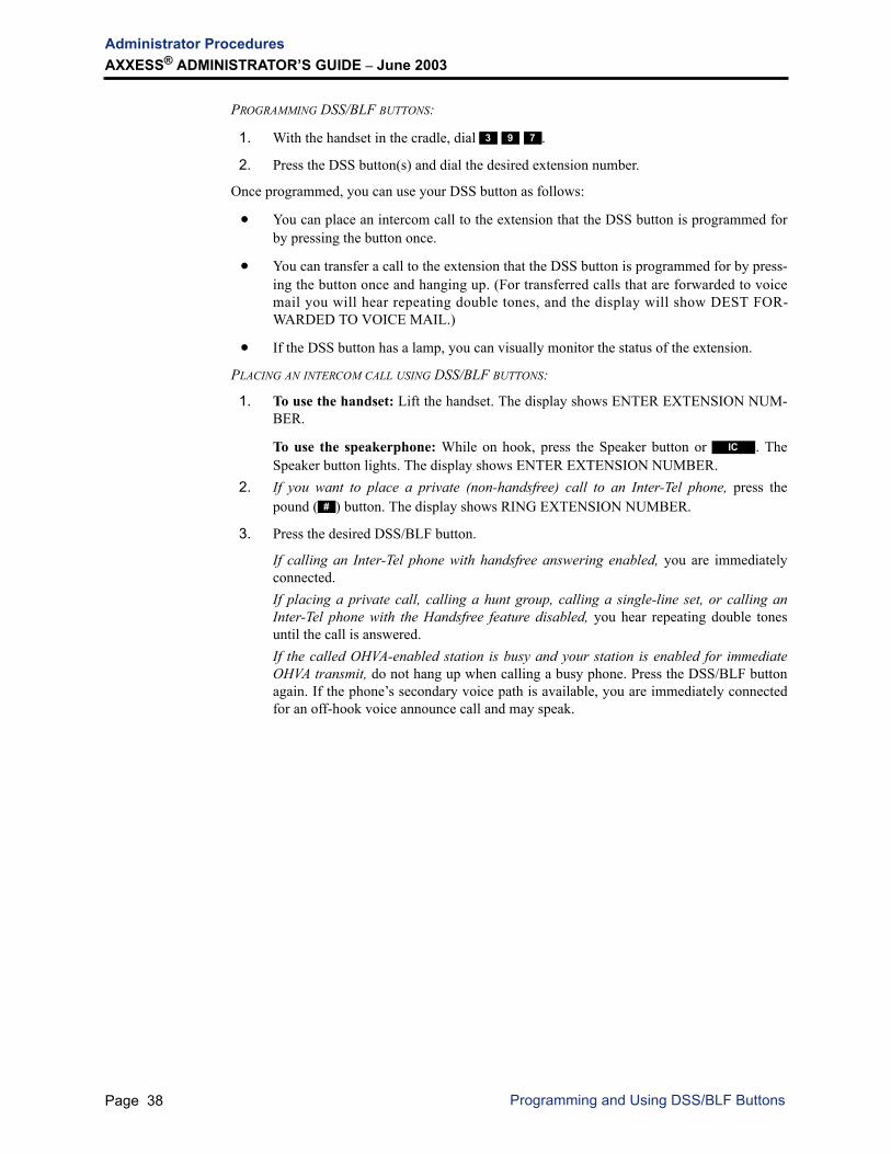
Administrator ProceduresAXXESS® ADMINISTRATOR’S GUIDE – June 2003
PROGRAMMING DSS/BLF BUTTONS:
1. With the handset in the cradle, dial .
2. Press the DSS button(s) and dial the desired extension number.
Once programmed, you can use your DSS button as follows:
• You can place an intercom call to the extension that the DSS button is programmed forby pressing the button once.
• You can transfer a call to the extension that the DSS button is programmed for by press-ing the button once and hanging up. (For transferred calls that are forwarded to voicemail you will hear repeating double tones, and the display will show DEST FOR-WARDED TO VOICE MAIL.)
• If the DSS button has a lamp, you can visually monitor the status of the extension.
PLACING AN INTERCOM CALL USING DSS/BLF BUTTONS:
1. To use the handset: Lift the handset. The display shows ENTER EXTENSION NUM-BER.
To use the speakerphone: While on hook, press the Speaker button or . TheSpeaker button lights. The display shows ENTER EXTENSION NUMBER.
2. If you want to place a private (non-handsfree) call to an Inter-Tel phone, press thepound ( ) button. The display shows RING EXTENSION NUMBER.
3. Press the desired DSS/BLF button.
If calling an Inter-Tel phone with handsfree answering enabled, you are immediatelyconnected.If placing a private call, calling a hunt group, calling a single-line set, or calling anInter-Tel phone with the Handsfree feature disabled, you hear repeating double tonesuntil the call is answered.If the called OHVA-enabled station is busy and your station is enabled for immediateOHVA transmit, do not hang up when calling a busy phone. Press the DSS/BLF buttonagain. If the phone’s secondary voice path is available, you are immediately connectedfor an off-hook voice announce call and may speak.
3 9 7
IC
#
Page 38 Programming and Using DSS/BLF Buttons

Administrator ProceduresAXXESS® ADMINISTRATOR’S GUIDE – June 2003
TRANSFERRING CALLS TO STATIONS:
1. While on a call, press the desired DSS/BLF button. The call is placed on transfer hold.
a. Transfer to a station that is forwarded to voice mail: You hear repeating doubletones and the display shows DEST FORWARDED TO VOICE MAIL.
b. Transfer to voice mail: The system waits for you to enter the mailbox number.The display shows ENTER MAILBOX. Enter the desired mailbox number. If youdo not enter a mailbox number before you hang up, the caller will be connected tothe voice mail unit and must enter the mailbox number after listening to the intro-ductory prompts.
c. Transfer-to-park: If transferring to a park location, hang up or press the Hold but-ton to complete the transfer. Then page the desired party and announce the call.The party must reverse transfer the call. Note that if the call is not answered, it willrecall your station if transferred directly, or it will recall the called transfer-to-parklocation’s attendant if transferred to hold.
2. If desired, wait for an answer and announce the call. If you are calling a device thatdoes not accept handsfree calls (such as an automated attendant or transfer-to-park loca-tion), the display shows HANG UP TO FINISH TRANSFER.
3. You have the following options:
To complete the transfer: Hang up or press another Call button. The display showsCALL TRANSFERRED TO (username).To transfer the call to hold: Press the Hold button or press and enter the Indi-vidual Hold feature code (336). The call will not ring or send call waiting signals untilthe Hold timer expires.To try another station: Press another DSS/BLF button.
To return to the caller: Press the lit Call button, trunk button, or button.REVERSE TRANSFERRING (PICKING UP A CALL RINGING OR HOLDING AT ANOTHER EXTENSION):
EITHER, enter the Reverse Transfer feature code (4) and then press the DSS/BLFbutton of the station where the call is ringing.OR, press the desired DSS/BLF button, and then press and enter the ReverseTransfer feature code (4).
∞
IC
∞
Page 39Programming and Using DSS/BLF Buttons

Administrator ProceduresAXXESS® ADMINISTRATOR’S GUIDE – June 2003
VOICE MAIL ADMINISTRATOR FEATURES
The voice mail administrator can use special features that are not provided to other mailboxowners. The system administrator mailbox has all standard mailbox features plus the ability todo the following:
• Record a broadcast message
• Perform mailbox and group list maintenance
• Create and select custom audiotex recordings (voice mail company greetings, autoattendant recordings, call routing announcements, and hunt group overflow andannouncement station recordings)
• Import fax documents
• Customize voice mail prompts
To access the system administrator’s mailbox, the system administrator dials the voice mailaccess number, presses to access the main menu, enters the system administrator’s mailboxnumber, then presses to reach the System Administrator Menu. (There is not a prompt forentering the .)
BROADCAST MESSAGES
The system administrator has the ability to make a single recorded message and send it to allStandard and Receive-Only mailboxes. (Extension IDs do not receive Broadcast Messages.)
TO RECORD A BROADCAST MESSAGE:
1. Dial the voice mail application access number. You hear the main menu.
2. During or after the greeting, press to identify yourself as a mailbox owner.
3. Enter the system administrator mailbox number and password.
4. Press to access the System Administrator Menu.
5. When you hear the System Administrator Menu list of options, press to send abroadcast message.
6. Record your message.
To pause while recording: Press . To continue, press any button except .
To erase and re-record your message: Press .
If you exceed the maximum allotted time for message length, a prompt will notify youand allow you to re-record the message or send it.
If voice mail is full, a message will notify you that it cannot accept your message. Hangup and try again later.
7. When you have completed your message, you have the following options:
If you are satisfied with your message, hang up. OR press for more options.
If you wish to hear your message, press .
If you wish to add to your message, press and continue your message as described instep 6.
To erase and re-record your message, press .
9
9
9
1
2 0
3
#
1
2
3
Page 40 Voice Mail Administrator Features
Administrator ProceduresAXXESS® ADMINISTRATOR’S GUIDE – June 2003
MAILBOX/GROUP LIST MAINTENANCEUsing the system administrator’s mailbox, the administrator may provide basic voice mailmailbox and group list system maintenance. This maintenance includes the following:
• Record the name of a standard mailbox, extension ID, or a group list
• Record the mailbox greeting and set personal options for a mailbox
• Set the password for a mailbox or extension ID
NOTE: To provide system security, all mailboxes and extension IDs should have a password.To make the passwords difficult to guess, they should not match the mailbox number or consistof one digit repeated several times. This is especially important in the system administrator'smailbox which allows programming access to the other mailboxes.
The system administrator does not need to know the mailbox’s password to perform mainte-nance on another mailbox.
TO PERFORM MAILBOX/GROUP LIST MAINTENANCE:
1. Dial the voice mail application access number. You hear the main menu.
2. During or after the greeting, press to identify yourself as a mailbox owner.
3. Enter the system administrator mailbox number and password.
4. Press to access the System Administrator Menu.
5. When you hear the System Administrator Menu list of options, press to access theMailbox/Group List Maintenance option.
6. Dial the mailbox, extension ID, or group list number to be accessed.
If programming a mailbox or extension ID, you hear the Personal Options menu. Fol-low the instructions on page 283 to program the personal options (name, password,message envelope, or greeting) for the selected mailbox.
If programming a group list, the current name is played. You are prompted to enter aname. After the tone, record the name for the selected list. When you are finished, press
. Then press again to accept the name. (Or, press to replay the name you justrecorded, or to erase and re-record it.)
9
2
# # 1
3
Page 41Mailbox/Group List Maintenance

Administrator ProceduresAXXESS® ADMINISTRATOR’S GUIDE – June 2003
IMPORTING FAX DOCUMENTS
If you have a fax card in your Voice Processor, you can use the voice mail administrator’smailbox to import fax documents. Imported documents can then be requested by callers whouse the Call Routing Announcement application that is programmed to provide the Fax-On-Demand service.TO IMPORT A FAX DOCUMENT:
1. Using a fax machine, dial the voice mail application access number. You hear the mainmenu.
2. During or after the greeting, press to identify yourself as a mailbox owner.
3. Enter the system administrator mailbox number and password.
4. Press to access the System Administrator Menu.
5. When you hear the System Administrator Menu list of options, press to select theImport Fax option. (Note that, if the Fax-On-Demand feature is not enabled, the systemwill not accept this digit). The system may inform you of one the following, if not, con-tinue to the next step.All system fax ports are busy: Hang up and try again later.The system already contains the maximum number of fax documents allowed: Until oneor more fax documents are deleted from the system, there is no room for additional doc-uments.The system does not have enough disk space to import any more documents: Until oneor more fax documents are deleted from the system, there is no room for additional doc-uments.The system currently is at or above the Maximum Fax Library Size: Until one or morefax documents are deleted from the system, there is no room for additional documents.
6. When prompted, enter the fax document number. (Or, to exit to the System Administra-tor Menu, press .) One of the following occurs when you enter the number:
If the document number does not already exist, the system asks you to verify the num-ber. Press if the number is correct and go to the next step. Or, press if you wishto re-renter the number.If the document number already exists, the system asks if you wish to replace it. Press
if you wish to replace the document and go to the next step. Or, press if youwish to re-renter the number.If the document is currently being sent, updated, or deleted, that document number can-not be used right now. You are prompted to enter a new number. Repeat step 6.If you did not enter a valid number, you are prompted to enter a new number. Repeatstep 6.
7. When prompted, press the Start button on your fax machine. One of the following mayoccur: If the system cannot communicate with your fax machine, check that it is working prop-erly and press to try again.
If the system runs out of disk space while importing the document or if the documentwill cause the system to exceed the Maximum Fax Library Size, you cannot import thisdocument until one or more fax documents have been deleted from the system to createdisk space. Press to return to step 6.
8. When the fax transmission is complete, the system tells you that the document wasreceived. Press to continue importing documents, or press to exit.
9
4
# 3
# 3
#
#
#
Page 42 Importing Fax Documents

Administrator ProceduresAXXESS® ADMINISTRATOR’S GUIDE – June 2003
CUSTOM AUDIOTEX RECORDINGSThe voice mail administrator can create and select up to 500 custom audiotex recordings (voicemail company greetings, auto attendant greetings, call routing announcements, and hunt groupannouncement/overflow recordings). Each recording has an assigned number. Numbers arethen assigned to specific applications using the system administrator’s mailbox or throughDatabase Programming.
Any recording number (001-500) can be assigned to any Voice Processor application. In thedefault state, Recording 001 is automatically defaulted to play the system-provided voice mailmain greeting, and Recording 002 is the Automated Attendant main greeting. The defaultrecordings can be changed, but will be returned to system-provided values if the Voice Proces-sor is defaulted. A single recording may be used for multiple applications.
After making the required recordings, the system administrator must determine which onesplay during the telephone system’s day and night modes of operation. This can be done fromeither the system administrator’s mailbox or through Database Programming.
The system administrator must enter a valid three-digit recording number (or a single digit fol-lowed by for recordings 1-9) before a custom audiotex recording can be made. If a validnumber has been entered and a previous recording exists, the Voice Processor will play it.(This includes the two standard default greetings.) When no recording is associated with arecording number, the system administrator will be prompted to create a recording.
Once the recording is installed, it replaces any previous recording. The only recordings thatcan be retrieved are system default recordings 001 and 002. They can be retrieved by default-ing the Voice Processor database.
The maximum recording time for each custom audiotex recording is determined in DatabaseProgramming when the maximum greeting lengths are established for all mailbox owners.
In Database Programming, several greetings can be linked together for one application and/oruse the special UCD/ACD hunt group characters that tell the caller how many calls are aheadand how long the wait will be. If you use the system administrator’s mailbox to record orassign a recording to an application with a list of several recordings, your input will changeonly the first entry in the list. You cannot change the other entries using the system administra-tor’s mailbox.
#
Page 43Custom Audiotex Recordings

Administrator ProceduresAXXESS® ADMINISTRATOR’S GUIDE – June 2003
TO RECORD CUSTOM AUDIOTEX RECORDINGS:
1. Dial the voice mail application access number. You hear the main menu.
2. During or after the greeting, press to identify yourself as a mailbox owner.
3. Enter the system administrator mailbox number and password.
4. Press to access the System Administrator Menu.
5. When you hear the System Administrator Menu, press to select the Custom Record-ings option.
6. The next prompt asks if you wish to make a custom recording or select a customrecording. Press (make a recording).
7. When prompted, enter the desired recording number (001-500). If a recording exists, itis played. If not, go to the next step. After the recording has played, you have the fol-lowing options:
To hear the recording again, press .
If you wish to leave the recording unchanged, press .
If you wish to re-record the recording, press and continue to the next step.
8. When prompted, record the greeting or message.
To pause while recording, press . To continue, press any button.
If you exceed the maximum allotted time for recording length, a prompt will notify youand allow you to re-record or save it.
If the Voice Processor PC disk is full, a prompt will notify you that it cannot accept yourrecording. Hang up and try again later.
9. When you have completed your recording, you have the following options:
If you are satisfied with your recording, hang up. Or, press for more options.
If you wish to hear your recording, press .
If you wish to add to your recording, press and continue your recording as describedin step 3.
To erase and re-record your recording, press .
TO ASSIGN CUSTOM AUDIOTEX RECORDINGS TO SPECIFIC APPLICATION EXTENSION NUMBERS:
1. Dial the voice mail access number. You hear the main menu.
2. During or after the greeting, press to identify yourself as a mailbox owner.
3. Enter the system administrator mailbox number and password.
4. Press to access the System Administrator Menu.
5. When you hear the System Administrator Menu list of options, press to select theCustom Recordings options.
6. The next prompt asks if you wish to make a custom recording or select a customrecording. Press (select a recording).
9
3
1
1
#
3
2
#
1
2
3
9
3
2
Page 44 Custom Audiotex Recordings
Administrator ProceduresAXXESS® ADMINISTRATOR’S GUIDE – June 2003
7. When prompted, enter the extension number of the application to be programmed. (Forexample, if users dial 299 to reach voice mail, enter 299 to program the voice mailgreeting.) Or, press to exit to the System Administrator Menu.
8. When prompted, select whether the recording will be played during day mode (bypressing ) or during night mode (by pressing ).
9. When prompted, enter the desired recording number (001-500). If a recording exists, itis played. (If not, you hear a warning that the recording has not yet been made.)
10. If it is the correct recording, press . Return to step 7.
CUSTOMIZED VOICE MAIL PROMPTS
All of the pre-recorded prompts in the Voice Processor can be customized, using the voice mailadministrator’s mailbox.
If the Multilingual feature is enabled, and the Secondary Language prompts have been loaded,the system administrator can change either the Primary or Secondary Language prompts. Whenthe system administrator’s phone is in the Primary Language mode, those prompts will bechanged when the following procedure is performed. If the system administrator’s phone is inSecondary Language mode, those prompts will be changed.
A list of all pre-recorded prompt numbers (001-595) and their text is provided in Figure 4,beginning on page 47. The Secondary Language prompts have the equivalent text in the sameprompt numbers. If you change any of the prompts, you should create a chart that shows thenew text.
NOTE: If you change the text of the prompts, be sure you keep the content similar to thedefault text. Otherwise, the prompts will not make sense to the listeners when played by voicemail.
TO RECORD CUSTOM SYSTEM PROMPTS (OR RESTORE SYSTEM PROMPTS):
1. Dial the voice mail application access number. You hear the main menu.
2. During or after the greeting, press to identify yourself as a mailbox owner.
3. Enter the system administrator mailbox number and password.
4. Press to access the System Administrator Menu.
5. When you hear the System Administrator Menu, press to select the System PromptReplacement option.
6. Enter the desired prompt number (001-545) followed by or the ACCEPT menu but-ton. If the number is valid, the current system and/or custom prompt is played. (If thenumber is not valid, you hear an error message and must choose another prompt num-ber.)
7. Do one of the following:
To hear the prompt again, press .
If you wish to replace the current system or custom prompt with a new custom prompt,press and continue to the next step.
To delete a custom prompt and reinstate the system prompt, press .
If you wish to leave the prompt unchanged and return to the previous menu, press .
1 2
#
9
6
#
1
3
9
Page 45Custom Audiotex Recordings
Administrator ProceduresAXXESS® ADMINISTRATOR’S GUIDE – June 2003
8. Record the new prompt. (To pause while recording the prompt, press . To continue,press any button.)
If the Voice Processor PC disk is full, a prompt will notify you that it cannot accept yourprompt. Hang up and try again later.
9. When you have completed recording your prompt, you have the following options:
If you are satisfied with your prompt, hang up.
If you wish to hear your prompt, press .
If you wish to add to your prompt, press and continue as described in step 8.
To erase and re-record your prompt, press .
2
1
2
3
Page 46 Custom Audiotex Recordings

Administrator ProceduresAXXESS® ADMINISTRATOR’S GUIDE – June 2003
FIGURE 4. Default Voice Mail Prompts
PROMPT CONTENT
001 To leave a message, please enter a mailbox number.002 For the directory, press pound.003 To reach an operator, press 0.004 I'm sorry...005 ...is not available.006 The number entered is not valid.007 Using the buttons on your telephone, please spell the last name of the person,
then press POUND. For the letter Q, press 7. For the letter Z, press 9.008 To exit the directory, press STAR.009 Mailbox number...010 If this is correct, press POUND.011 For the previous name in the directory, press 1.012 To hear additional information, press 2.013 To hear the next directory name, press 3.014 To spell a new name, press 4.015 Extension number...017 ...is not a valid choice.018 Please try again.019 After the tone, please record your message. When finished, you may hang up to
deliver the message or press POUND for more options.020 Message delivered.021 To replay, press 1.022 To erase and re-record, press 3.023 To append this recording, press 2.024 To accept, press POUND.025 Please record after the tone. To end, press POUND.026 Recording erased.027 Recording stopped.028 Please begin speaking after the tone.029 Message play stopped. To continue, press POUND.030 Enter the destination mailbox or group list number.031 Logon canceled.032 Enter your password. Then press POUND.033 There have been 3 invalid attempts to log onto your mailbox.034 Invalid password.035 Thank you for calling. Good-bye.036 To access voice mail features, you must change your system-assigned pass-
word.037 You have not finished setting up your mailbox.038 Subscriber access denied.039 Because this is the first time you are accessing your mailbox, you must record
your name for the company directory.
Page 47Default Voice Mail Prompts

Administrator ProceduresAXXESS® ADMINISTRATOR’S GUIDE – June 2003
040 Since you are accessing your mailbox for the first time, you should be aware of a few standard features. To cancel an option you have accessed and return to the previous menu, press STAR. To accept your recording or dialing sequence, or to advance to your next message, press POUND. For help, you may press 0 at any time you are at a menu and voice mail will replay the current menu and or give you additional information. Certain voice mail features such as remote messaging are available from your mailbox only if authorized by your system administrator. Your mailbox is now fully set up.
041 Your password may be up to 12 digits.042 Enter your new password, then press POUND. If you don't want a password,
press POUND now.043 You new password is...044 The number entered is too long.045 To accept this entry, press POUND.046 To erase and re-enter, press 3.047 Password erased.048 Password saved.049 Your mailbox is full and cannot receive any new messages. Please delete old
messages.050 Not used.051 Not used.052 Your mailbox is almost full. Please delete any messages you no longer need so
new messages may arrive.053 You have...054 You have one new message.055 ...new messages.056 ...of which is priority.057 You have no new messages.058 You have one saved message.059 ...saved messages.060 Remote messaging is currently enabled.061 To listen to new messages, press 1.062 To record a message, press 2.063 To listen to saved messages, press 3.064 For personal options, press 4.065 To setup remote messaging, press 5.066 For your primary setup, press 1.067 For your alternate setup, press 2.068 If this is the correct destination, press POUND.069 To send this message now, press POUND.070 For special delivery options, press 9.071 To return to the previous menu, press STAR.072 Message canceled.073 To mark this message private, press 1.074 To mark this message for certified delivery, press 2.
PROMPT CONTENT (Continued)
Page 48 Default Voice Mail Prompts

Administrator ProceduresAXXESS® ADMINISTRATOR’S GUIDE – June 2003
075 To mark this message priority, press 3.076 Message marked private.077 Message marked certified.078 Message marked priority.079 To send this message to additional mailboxes, press POUND.080 To backup within your message or recording, press 1.081 To pause at any time, press 2.082 To advance press 3.083 To lower the voice mail volume, press 4.084 To increase volume, press 6.085 To save this message, press 7.086 To delete this message, press 9.087 To skip to the end of your message or re cording, press POUND.088 To return to the main menu, press STAR.089 To reply to this message, press 2.090 To forward a copy of this message to another destination, press 3.091 To skip back to the previous message, press 4.092 To replay the message envelope, press 5.093 To listen to your next message, press 6.094 There are no previous messages.095 Message saved.096 Message deleted.097 There are no further messages.098 Message received...099 ...at...100 ...from...101 ...totaling...102 ...minutes...103 ...minute...104 ...seconds...105 ...second...106 Message received from an outside caller.107 To record an introduction with a copy of this message, press 1.108 To change your personal greeting, press 1.109 To change your name in the directory, press 2.110 To change your password, press 3.111 To change your message envelope, press 4.112 To replay the message, press 1.113 To use your primary greeting, press 1.114 To select your alternate greeting, press 2.115 To select the system greeting, press 3.116 After the tone, please record your greeting, then press POUND.
PROMPT CONTENT (Continued)
Page 49Default Voice Mail Prompts

Administrator ProceduresAXXESS® ADMINISTRATOR’S GUIDE – June 2003
117 Greeting saved.118 After the tone, please record your name, then press POUND.119 Name saved.120 Your message envelope is currently set to return...121 ...all information.122 ...time and date...123 ...message source...124 ...and...125 ...message length...126 To turn on all envelope options, press 4.127 For message source, press 2.128 For message length, press 3.129 This option is now off.130 This option is now on.131 For time and date, press 1.132 Your message envelope will play all options.133 ...is turned on to call you at...134 AM135 PM136 ...Extension ID number...137 ...Every day.138 ...Monday through Friday.139 Sunday140 Monday141 Tuesday142 Wednesday143 Thursday144 Friday145 Saturday146 To turn this number on or off, press 1.147 To change the phone number, press 2.148 To change times of day, press 2.149 To change days of the week, press 3.150 For pager notification, press 1.151 For personal phone notification, press 2.152 For notification of all new messages, press 1.153 For priority-only, press 2.154 Please enter the destination telephone number and wait for further instructions.155 The new number is...156 Please enter the start time.157 Please enter the stop time.158 I'm sorry. You must program a telephone number first.
PROMPT CONTENT (Continued)
Page 50 Default Voice Mail Prompts

Administrator ProceduresAXXESS® ADMINISTRATOR’S GUIDE – June 2003
159 Invalid time.160 For AM, press 1.161 Please select the days of the week on which you wish to be notified.162 Not used.163 Please enter your mailbox number.164 Today165 Yesterday166 January167 February168 March169 April170 May171 June172 July173 August174 September175 October176 November177 December178 First179 Second180 Third181 Fourth182 Fifth183 Sixth184 Seventh185 Eighth186 Ninth187 Tenth188 Eleventh189 Twelfth190 Thirteenth191 Fourteenth192 Fifteenth193 Sixteenth194 Seventeenth195 Eighteenth196 Nineteenth197 Twentieth198 Twenty-first199 Twenty-second200 Twenty-third
PROMPT CONTENT (Continued)
Page 51Default Voice Mail Prompts

Administrator ProceduresAXXESS® ADMINISTRATOR’S GUIDE – June 2003
201 Twenty-fourth202 Twenty-fifth203 Twenty-sixth204 Twenty-seventh205 Twenty-eighth206 Twenty-ninth207 Thirtieth208 Thirty-first209 ...the voice mail system.210 The system is set to notify you between...211 ...is turned off.212 ...is turned on to call your pager at...213 ...with all new messages.214 ...with all priority messages.215 ...starting at...216 ...ending at...217 For mailbox and group list maintenance, press 2.218 To send a message to all subscribers, press 1.219 To make a custom recording, press 1.220 To select a custom recording, press 2.221 Not used.222 Please enter the recording number.223 After the tone, please record. Then press POUND.224 Recording saved.225 To continue recording, press POUND.226 Not used.227 No saved messages.228 To change and spell the first name, press 5.229 To change and spell the last name, press 5.230 Using the buttons on your telephone, please spell the first name of the person.
Then press POUND. For the letter Q, press 7. For the letter Z, press 9.231 No message left.232 ...last...233 ...an outside caller at...234 Message was sent from...235 This matches the mailbox of...236 ...an unknown caller.237 To turn off the envelope, press 5.238 To accept the changes, press POUND.239 The envelope is turned off.240 Please enter the application extension number.241 To select a day recording, press 1.242 To select a night recording, press 2.
PROMPT CONTENT (Continued)
Page 52 Default Voice Mail Prompts

Administrator ProceduresAXXESS® ADMINISTRATOR’S GUIDE – June 2003
243 If this is the correct recording, press POUND.244 Warning, no recording has been made.245 Invalid application entered.246 ...is not a valid recording number.
247-252 Not used.253 This is a return receipt verifying the message sent has been heard.254 I'm sorry. Private messages cannot be for warded.255 This is the message center calling for...256 If you are the correct person, press POUND.257 ...One258 ...Two259 ...Three260 ...Four261 ...Five262 ...Six263 ...Seven264 ...Eight265 ...Nine266 ...Ten267 ...Eleven268 ...Twelve269 ...Thirteen270 ...Fourteen271 ...Fifteen272 ...Sixteen273 ...Seventeen274 ...Eighteen275 ...Nineteen276 ...Twenty277 ...Thirty278 ...Forty279 ...Fifty280 ...Sixty281 ...Seventy282 ...Eighty283 ...Ninety284 ...Hundred285 This mailbox is currently full and cannot receive new messages.286 Oh287 ...of which are priority.288 Priority message received...289 Otherwise, press STAR.
PROMPT CONTENT (Continued)
Page 53Default Voice Mail Prompts

Administrator ProceduresAXXESS® ADMINISTRATOR’S GUIDE – June 2003
290 When you are finished entering mailbox numbers, press POUND.291 Otherwise, press POUND.292 For PM, press 2.293 For Sunday, press 1.294 For Monday, press 2.295 For Tuesday, press 3.296 For Wednesday, press 4.297 For Thursday, press 5.298 For Friday, press 6.299 For Saturday, press 7.300 For Monday through Friday service, press 1.301 For all the days of the week, press 2.302 Thousand303 The hard disk is...304 ...percent full.305 I'm sorry. Voice mail is full and cannot re cord any messages.306 Zero307 POUND308 STAR309 Group list number...310 Please speak louder.311 You have recorded for the maximum time permitted.312 Not used.313 Resuming playback.314 You have one priority message.315 Use 2 digits for the hour and 2 digits for the minutes.
316-317 Not used.318 You have chosen not to have a password.319 I'm sorry. This mailbox is currently in use and cannot be accessed. Please try
again later.320 Not used.321 If you are calling from a rotary-type telephone, please stay on the line and your
call will be answered.322 You can not reply to a system sent message.323 Zero is not a valid entry. To spell a name, please press one number on the tele-
phone dialpad for each letter of the person's name you are entering. For the let-ter A, press the number 2 button one time and for the letter F, press the number 3 button one time. When you are finished, press POUND.
324 Zero is not a valid entry. To spell a name, please press the associated number on the telephone dialpad with the desired letter of the person's name you are entering. For the letter A, press the number 2 button once. for the letter B, press it twice and for the letter C, three times. When you are finished, press POUND.
325 Please select the days of the week.326 To select individual week days, press 3.
PROMPT CONTENT (Continued)
Page 54 Default Voice Mail Prompts

Administrator ProceduresAXXESS® ADMINISTRATOR’S GUIDE – June 2003
327 Service is set for Monday through Friday.328 Service is set for each day of the week.329 Recording canceled.330 The system was busy and could not deliver message notification at the speci-
fied time.331 The system was unable to deliver message notification due to a programming
error.332 Extension ID...333 ...the operator.334 ...the operator...335 Remote Messaging will call...336 To change a cascade level, press 1.337 To select a message notification category, press 4.338 Please enter the cascade level you wish to program.339 ...with a pager number of...340 To change the pager dial string, press 3.341 To call an internal extension, press 1.342 To call an outside number, press 2.343 Not used.344 Please enter the digits for your digital pager and wait for further instructions.345 The new pager number is...346 Mailbox Number347 New Message Count348 Pause349 You must program a telephone number first.350 You have chosen not to have a pager number.351 Cascade Level...352 You did not enter a valid document number.353 This document is currently unavailable.354 ... is not a valid document number.355 You have already selected that document.356 To cancel, press STAR.357 You have selected the maximum number of documents allowed.358 To send your fax, press pound.359 You have selected one document.360 You haven't selected any documents yet.361 You may select one more document during this call.362 You may select up to...363 ... more documents during this call.364 Selections Canceled.365 The number that will appear on your fax cover sheet is...366 You have chosen not to have your extension appear on your cover sheet.
PROMPT CONTENT (Continued)
Page 55Default Voice Mail Prompts
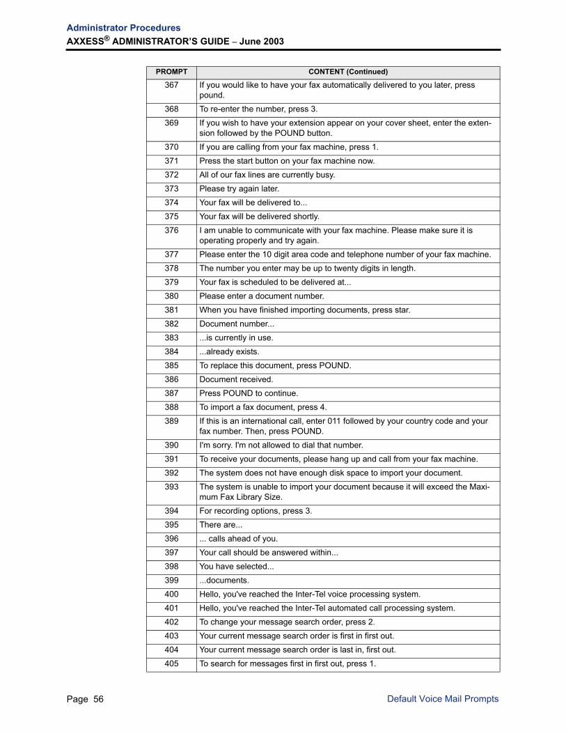
Administrator ProceduresAXXESS® ADMINISTRATOR’S GUIDE – June 2003
367 If you would like to have your fax automatically delivered to you later, press pound.
368 To re-enter the number, press 3.369 If you wish to have your extension appear on your cover sheet, enter the exten-
sion followed by the POUND button.370 If you are calling from your fax machine, press 1.371 Press the start button on your fax machine now.372 All of our fax lines are currently busy.373 Please try again later.374 Your fax will be delivered to...375 Your fax will be delivered shortly.376 I am unable to communicate with your fax machine. Please make sure it is
operating properly and try again.377 Please enter the 10 digit area code and telephone number of your fax machine.378 The number you enter may be up to twenty digits in length.379 Your fax is scheduled to be delivered at...380 Please enter a document number.381 When you have finished importing documents, press star.382 Document number...383 ...is currently in use.384 ...already exists.385 To replace this document, press POUND.386 Document received.387 Press POUND to continue.388 To import a fax document, press 4.389 If this is an international call, enter 011 followed by your country code and your
fax number. Then, press POUND.390 I'm sorry. I'm not allowed to dial that number.391 To receive your documents, please hang up and call from your fax machine.392 The system does not have enough disk space to import your document.393 The system is unable to import your document because it will exceed the Maxi-
mum Fax Library Size.394 For recording options, press 3.395 There are...396 ... calls ahead of you.397 Your call should be answered within...398 You have selected...399 ...documents.400 Hello, you've reached the Inter-Tel voice processing system.401 Hello, you've reached the Inter-Tel automated call processing system.402 To change your message search order, press 2.403 Your current message search order is first in first out.404 Your current message search order is last in, first out.405 To search for messages first in first out, press 1.
PROMPT CONTENT (Continued)
Page 56 Default Voice Mail Prompts

Administrator ProceduresAXXESS® ADMINISTRATOR’S GUIDE – June 2003
406 To search for messages last in first out, press 2.407 To change the search order for new messages, press 1.408 To change the search order for saved messages, press 2.
409-499 Not used.500 If you know your party's extension number, enter it now.501 To leave a message, press 1.502 To try another extension, press 2.503 Please hold while your call is being transferred to...504 Not used.505 To return to the menu, press 2.506 Your fax is scheduled to be delivered on...507 The system already contains the maximum number of fax documents allowed.508 The system does not have enough disk space to import any more documents.509 The system is currently at or above the Maximum Fax Library Size.510 Levels 1 through 9 are currently disabled.511 Your call will be answered in the order it was received.512 There is one call ahead of you.513 To change your transfer method, press 5.514 Your current transfer method is unannounced.515 Your current transfer method is screened.516 Your current transfer method is announce only.517 To select unannounced transfers, press 1.518 For screened transfers, press 2.519 For announce only, press 3.520 Who should I say is calling?521 To replay the announcement, press 1.522 To send this call to voice mail, press 2.523 To forward this call to another extension, press 3.524 To accept this call, press POUND.525 To refuse this call, press STAR.526 You have a call from...
527-534 Not used.535 Please enter the extension number.
536-537 Not used.538 For system prompt replacement or reinstatement, press 6.539 Please enter the number of the system prompt.540 The system prompt has been replaced by the following custom prompt...541 The original system prompt is...542 To replace this system prompt with a custom prompt, press 3.543 ...is not a valid system prompt number.544 To delete the custom prompt and reinstate the system prompt, press 9.545 To replace this custom prompt with a new custom prompt, press 3.
PROMPT CONTENT (Continued)
Page 57Default Voice Mail Prompts

Administrator ProceduresAXXESS® ADMINISTRATOR’S GUIDE – June 2003
546 You have no deleted messages.547 You have one deleted message.548 ...deleted messages.549 To recover deleted messages, press 2.550 To recover this message, press 7.551 Message recovered.552 To purge this message, press 9.553 Message purged.554 To listen to deleted messages, press 1.555 To recover all messages, press 2.556 To purge all messages, press 3.557 ...messages recovered.558 ...messages purged.559 ...message recovered.560 ...message purged.561 For message options, press 5.562 For more options, press 9. 563 To change the fax destination number, press 1.564 Please enter the extension number of your fax destination, followed by the [#]
button.565 Your fax destination is...566 You have chosen not to have a fax destination.567 Invalid extension.568 Fax destination saved.569 Fax destination erased.570 To cancel unheard sent messages, press 1.571 All sent messages have been heard.572 Enter the destination mailbox.573 This mailbox has one unheard message.574 ...unheard messages.575 To append to the message, press 2.576 To leave a voice mail message, press 1.577 To make a return call, press 2.578 Please hold while your call is being transferred to an outside number.
579-580 Not used.581 …has just listened to the original message.582 This mailbox has...
583-591 Not used.592 I'm sorry. I'm not allowed to dial that number.593 Message received from an outside number with no caller ID information.594 I'm sorry. I do not have valid Caller ID information.595 ...the network...596 Your call is being handled by the Inter-Tel voice processing system.
PROMPT CONTENT (Continued)
Page 58 Default Voice Mail Prompts

Administrator ProceduresAXXESS® ADMINISTRATOR’S GUIDE – June 2003
FIGURE 5. Administrator Database Programming Planning Sheets
CUSTOM AUDIOTEX RECORDINGS: If you record special recordings for the Voice Processor applications(see page 45 for instructions), record the information here:
RECORDING # TEXT WHERE USED (EXT #)
Sample Thank you for calling XYZ Company. All of our representatives are busy right now. Please hold.
Ext.2011 (Hunt Group Overflow Station)
Page 59Administrator Database Programming Planning Sheets

Administrator ProceduresAXXESS® ADMINISTRATOR’S GUIDE – June 2003
FIGURE 5. Administrator Database Programming Planning Sheets (Continued)
STATION PROGRAMMING: For each station to be programmed, record the following information:
SYSTEM PROGRAMMING: Record the following system-wide information:
Administrator Database Programming Password: ___________________________
Do-Not-Disturb Messages:
Station Extension #:Administrator station? Yes or NoAttendant station? Yes or NoHouse Phone? Yes or NoThis station's attendant:Username:Toll restriction classes of service:
DEFAULT MESSAGE PRIMARY LANGUAGE MESSAGE SECONDARY LANG. MESSAGE
MESSAGE 01 (DO-NOT-DISTURB)MESSAGE 02 (LEAVE A MESSAGE)MESSAGE 03 (IN MEETING UNTIL)MESSAGE 04 (IN MEETING)MESSAGE 05 (ON VACATION 'TIL)MESSAGE 06 (ON VACATION)MESSAGE 07 (CALL ME AT)MESSAGE 08 (AT THE DOCTOR)MESSAGE 09 (ON A TRIP)MESSAGE 10 (ON BREAK)MESSAGE 11 (OUT OF TOWN 'TIL)MESSAGE 12 (OUT OF OFFICE)MESSAGE 13 (OUT UNTIL)MESSAGE 14 (WITH A CLIENT)MESSAGE 15 (WITH A GUEST)MESSAGE 16 (UNAVAILABLE)MESSAGE 17 (IN CONFERENCE)MESSAGE 18 (AWAY FROM DESK)MESSAGE 19 (GONE HOME)MESSAGE 20 (OUT TO LUNCH)
Page 60 Administrator Database Programming Planning Sheets

Administrator ProceduresAXXESS® ADMINISTRATOR’S GUIDE – June 2003
FIGURE 5. Administrator Database Programming Planning Sheets (Continued)
Reminder Messages:
DEFAULT MESSAGE PRIMARY LANGUAGE MESSAGE SECONDARY LANG. MESSAGE
MESSAGE 01 (MEETING):MESSAGE 02 (STAFF MEETING):MESSAGE 03 (SALES MEETING):MESSAGE 04 (CANCEL MEETING):MESSAGE 05 (APPOINTMENT):MESSAGE 06 (PLACE CALL):MESSAGE 07 (CALL CLIENT):MESSAGE 08 (CALL CUSTOMER):MESSAGE 09 (CALL HOME):MESSAGE 10 (CALL CORPORATE):MESSAGE 11 (CALL ENGINEERING):MESSAGE 12 (CALL MARKETING):MESSAGE 13 (CALL ACCOUNTING):MESSAGE 14 (CANCEL DND):MESSAGE 15 (CANCEL CALL FWD):MESSAGE 16 (TAKE MEDICATION):MESSAGE 17 (MAKE RESERVATION):MESSAGE 18 (REVIEW SCHEDULE):MESSAGE 19 (LUNCH):MESSAGE 20 (REMINDER):
Page 61Administrator Database Programming Planning Sheets

Administrator ProceduresAXXESS® ADMINISTRATOR’S GUIDE – June 2003
FIGURE 5. Administrator Database Programming Planning Sheets (Continued)
Changing Station Extension Numbers:
Swapping Stations:
OLD EXTENSION NUMBER NEW EXTENSION NUMBER
EXTENSION NUMBER SWAPPED WITH EXTENSION
Page 62 Administrator Database Programming Planning Sheets

Administrator ProceduresAXXESS® ADMINISTRATOR’S GUIDE – June 2003
FIGURE 5. Administrator Database Programming Planning Sheets (Continued)
TRUNK PROGRAMMING:
Individual Trunks: Record the following information for each trunk to be programmed:
Trunk Groups: Record the following information for each trunk group to be programmed:
Answer Supervision Type: Polarity Reversal or Valid Call or Valid Call with Polarity Reversal
Caller ID? Yes or NoHybrid Balance: Normal or ShortSignaling: DTMF or Dial PulseTrunk Group Number:Username:
Stations with Day Answer Access:
Stations with Night Answer Access:
Stations with Day Ring In:
Stations with Night Ring In:
Toll Restriction Classes of Service:
Trunks in Trunk Groups:
Page 63Administrator Database Programming Planning Sheets

Administrator ProceduresAXXESS® ADMINISTRATOR’S GUIDE – June 2003
Page 64 Administrator Database Programming Planning Sheets

System HardwareAXXESS® ADMINISTRATOR’S GUIDE – June 2003
System HardwareCONTENTS PAGE
Introduction . . . . . . . . . . . . . . . . . . . . . . . . . . . . . . . . . . . . . . . . . . . . . . . . . . . . . . . . . . . . . 66Station Instruments . . . . . . . . . . . . . . . . . . . . . . . . . . . . . . . . . . . . . . . . . . . . . . . . . . . . . . 67
Inter-Tel Phones . . . . . . . . . . . . . . . . . . . . . . . . . . . . . . . . . . . . . . . . . . . . . . . . . . . . . . . 68Model 8000 Series, Standard Display Phone, Associate Display Phone and Basic Digital Phones Speakerphones . . . . . . . . . . . . . . . . . . . . . . . . . . . . . . . 68Executive and Professional Display Phone Speakerphones . . . . . . . . . . . . . . . . . . 68Enhanced Speakerphones for Digital Phones . . . . . . . . . . . . . . . . . . . . . . . . . . . . . 69Analog, Executone IDS, and Executone Wave Phone Speakerphones . . . . . . . . . 70Six-Line Liquid Crystal Display (LCD) . . . . . . . . . . . . . . . . . . . . . . . . . . . . . . . . . 70Two-Line LCD . . . . . . . . . . . . . . . . . . . . . . . . . . . . . . . . . . . . . . . . . . . . . . . . . . . . 72LCD Contrast Adjustment. . . . . . . . . . . . . . . . . . . . . . . . . . . . . . . . . . . . . . . . . . . . 72Node and Circuit Number on Power-Up. . . . . . . . . . . . . . . . . . . . . . . . . . . . . . . . . 72Keymaps . . . . . . . . . . . . . . . . . . . . . . . . . . . . . . . . . . . . . . . . . . . . . . . . . . . . . . . . . 73Default Inter-Tel Phone Feature Buttons . . . . . . . . . . . . . . . . . . . . . . . . . . . . . . . . 76Secondary Extension Appearances . . . . . . . . . . . . . . . . . . . . . . . . . . . . . . . . . . . . 77Light-Emitting Diode (LED) Indications . . . . . . . . . . . . . . . . . . . . . . . . . . . . . . . . 78Red and Green LEDs . . . . . . . . . . . . . . . . . . . . . . . . . . . . . . . . . . . . . . . . . . . . . . . 80Connecting a Headset . . . . . . . . . . . . . . . . . . . . . . . . . . . . . . . . . . . . . . . . . . . . . . . 80“Send Alert Burst To Headset” Station Flag . . . . . . . . . . . . . . . . . . . . . . . . . . . . . . 81Digital Phone Data Port Modules . . . . . . . . . . . . . . . . . . . . . . . . . . . . . . . . . . . . . . 81Data Port Module for 12-Line and 24-Line Analog Phones . . . . . . . . . . . . . . . . . . 82Optional Data Devices. . . . . . . . . . . . . . . . . . . . . . . . . . . . . . . . . . . . . . . . . . . . . . . 828-Line IMX AIM Analog Phones on Dual Circuits . . . . . . . . . . . . . . . . . . . . . . . . 85Digital Phone Desktop Interface . . . . . . . . . . . . . . . . . . . . . . . . . . . . . . . . . . . . . . 86Direct Station Selection/Busy Lamp Field (DSS/BLF) Units . . . . . . . . . . . . . . . . 87Mini-DSS Units. . . . . . . . . . . . . . . . . . . . . . . . . . . . . . . . . . . . . . . . . . . . . . . . . . . . 87
Single-Line Sets . . . . . . . . . . . . . . . . . . . . . . . . . . . . . . . . . . . . . . . . . . . . . . . . . . . . . . . 88Single-Line DTMF Sets . . . . . . . . . . . . . . . . . . . . . . . . . . . . . . . . . . . . . . . . . . . . . 88Single-Line Set Message Lamps . . . . . . . . . . . . . . . . . . . . . . . . . . . . . . . . . . . . . . . 88Single-Line Ring Zones and Extended Ring Cadences . . . . . . . . . . . . . . . . . . . . . 89Off-Premises Extensions (OPX) . . . . . . . . . . . . . . . . . . . . . . . . . . . . . . . . . . . . . . 90
AgentSet . . . . . . . . . . . . . . . . . . . . . . . . . . . . . . . . . . . . . . . . . . . . . . . . . . . . . . . . . . . . . 90IP Devices. . . . . . . . . . . . . . . . . . . . . . . . . . . . . . . . . . . . . . . . . . . . . . . . . . . . . . . . . . . . 91
Optional System Equipment . . . . . . . . . . . . . . . . . . . . . . . . . . . . . . . . . . . . . . . . . . . . . . . 92
Page 65

System HardwareAXXESS® ADMINISTRATOR’S GUIDE – June 2003
INTRODUCTION
The hardware houses the system power supply unit and the circuit cards. Together, the circuitcards in the phone system’s cabinet perform the switching activities for the system, detectincoming calls, process data-controlled features, and control the interaction of station instru-ments, trunks, intercom calls, and Voice Processor applications.
The basic cabinet has slots for up to seven circuit cards. For increased port capacity, two, three,or four basic cabinets may be connected together to form one expanded cabinet. For maximumcapacity, up to four dual-cabinet systems can be connected via an Asynchronous TransferMode (ATM) Switch, creating an eight-cabinet system.
The actual number of phones and lines available depends on the number and type of cards andstations installed on the system. For example, there could be as many as 512 outside lines, 448Inter-Tel phones, or 512 single-line sets, depending on the circuit card configuration.
The circuitry and software in the basic cabinet combine to produce an “integrated switchingmatrix” of 128 time slots (voice channels). A quad-cabinet system has 512 time slots.
With system software version 5.0 (and later), you can connect two or more systems to form anetwork that provides a seamless interface between the systems. To the user, the networkappears as though it is one integrated system. With few exceptions, the user can perform all ofthe functions across the network that can be performed on a single system.
Standard system hardware features include:
• A Central Processing Unit (CPU) Card for storing the system software programs, thecustomer’s database, and call processing history files.
• Light-emitting diode (LED) indicators for showing main processor operation, databaseerror occurrences, minor system alarms, and database back-up battery connection.
• External ports for connecting a personal computer (PC) or modem to program the sys-tem database and/or for connecting output devices for the Station Message DetailRecording (SMDR) and programming reports. Ports are also provided for the VoiceProcessor interface.
• Database back-up battery for preserving the system database in the event of a powerfailure.
• Reset switch to manually reset the system during troubleshooting.
• Easily accessible voltage test points for checking the system operating voltages.
• Relays for connecting power failure transfer equipment.
• Circuitry for connecting an external music source (radio, tape player, etc.).
Page 66 Introduction
System HardwareAXXESS® ADMINISTRATOR’S GUIDE – June 2003
STATION INSTRUMENTS
To allow system flexibility and cost efficiency, a variety of Inter-Tel and industry-standard 3rd-party station instruments can be used on the Inter-Tel phone system. These include:
• Digital Display Phones (Model 8560, Model 8520, Executive Display, Professional Dis-play, Standard Display, and Associate Display)
• Digital Non-Display Phones (Model 8500, Axxess Basic, and Eclipse Basic)
• AIM Analog Phones (8-, 12-, and 24-Line)
• Inter-Tel/DVK Analog Phones (8-, 12-, and 24-Line)
• GMX Analog Phones (12-, and 24-Line)
• IMX Analog Phones (8-, 12-, and 24-Line)
• Executone® IDS Phones (Model Numbers 160, 64, 32, 18, and 12, and Agent Termi-nals)
• Executone® Wave Phones (29- and 17-Button)
• Single-Line Sets
• DSS/BLF Units – single or tandem (60-,50-, and 48-Button)
• Mini-DSS Units (Available for Model 8560 and 8520 Phones Only)
• IP Devices
System software will support any configuration of station instruments with the limitation thatthere must be a minimum of one Keyset Card. The actual configuration is defined by the typeof cards and the number of circuits in use on the system.
Digital Keyset Cards (DKSC or DKSC-16) are used to support digital display and non-displayphones. Digital Keyset Card circuits can be equipped with a Single-Line Adapter (SLA) andprogrammed to support two single-line sets (instead of an Inter-Tel phone). The DKSC haseight circuits and the DKSC-16 has 16 circuits.
Each Analog Keyset Card (AKSC) and Executone Keyset Card (EKSC) provides up to 12 cir-cuits for connecting GMX and IMX Analog phones, Executone IDS phones, and ExecutoneWave phones and devices to the system.
The Single-Line Card (SLC) provides up to eight circuits for connecting on-premises AC-ring-ing single-line DTMF sets and playback devices.The SLC-16 can support up to 16 on-premisesAC-ringing single-line devices.
The IP Card (IPC) and device IP Resource Card (IPRC) support the IP Phone-Plus, IP Soft-Phone, Model 8660, and IP Single-Line Adapter (IP SLA), providing the functionality requiredto make phone calls through the IP network to the Inter-Tel telephone system. Each IP Card(IPC) can support up to eight IP devices, and each device IPRC can support up to 16 IPdevices.
NOTE: Throughout this guide, the term “Inter-Tel phone” refers to the full-feature phones man-ufactured and sold by Inter-Tel. The term does not apply to industry-standard single-line, dual-tone multi-frequency sets.
Page 67Station Instruments

System HardwareAXXESS® ADMINISTRATOR’S GUIDE – June 2003
INTER-TEL PHONES
The features supported by Inter-Tel phones are described in the following paragraphs.
Model 8000 Series, Standard Display Phone, Associate Display Phone and Basic Digital Phones Speakerphones
The following display and non-display digital phones have a built-in speaker and microphonethat allow the user to answer intercom calls handsfree, dial while on hook, monitor calls, andlisten to background music.
• Model 8000 Series Phones (8560, 8520, and 8500)
• Standard Display Phone
• Associate Display Phone
• Axxess Basic Digital Phone
• Eclipse Basic Digital Phone
These phones can be programmed in individual station programming to be allowed to use sys-tem resources for standard and enhanced speakerphones. Enhanced mode allows for full-duplex operation over a limited volume range (the range depends on trunk characteristics, typi-cally the range is 1-3). Enhanced speakerphones are explained below.
If a user presses the Speaker button while on hook, the standard switched speakerphone func-tion is activated and the speakerphone resource is assigned to that phone for the length of thecall. If a user requests the speakerphone function when speakerphone resources are not avail-able, the user will hear reorder tones, and the display will show NO SPKRPHN AVAIL STAYOFF HOOK.
If the user attempts to change to the speakerphone and hangs up during a call when speaker-phones are unavailable, the user will be forced into a monitor-only mode. The user will be ableto hear the other party but will not be allowed to transmit to them. In this mode, the user’s
button will be lit, and the display shows NO SPKRPHN AVAIL COME OFF HOOK.Pressing the lit button will result in a burst of reorder tone; you must lift the handset tospeak.
NOTE: On certain handsfree-to-handsfree intercom calls, voice volume levels may cause feed-back to occur. If this happens; one station user should pick up the handset. Two Display Phonescannot be in enhanced mode while on a call together; one phone must be off hook to allow theother phone to enter enhanced speakerphone mode. If both phones are on hook, there is nobenefit to having one phone in enhanced mode.
Executive and Professional Display Phone Speakerphones
Each Executive and Professional Display Phone has a built-in, integrated speakerphone thatallows on-hook dialing and handsfree operation on outside calls and inside (intercom) calls.The speakerphone can be used in standard mode or in enhanced mode which allows for full-duplex operation over a limited volume range (the range depends on trunk characteristics, typi-cally the range is 1-3). Enhanced speakerphones are explained on the next page.
The Executive and Professional’s speaker can also provide background music (if an externalmusic source is installed) and is used to receive pages.
A programming option can be used to disable the phone’s speakerphone capabilities. Or, theuser can disable the speakerphone for intercom calls using the Handsfree On/Off and/or RingIntercom Always On/Off feature code.
MUTE
MUTE
Page 68 Inter-Tel Phones

System HardwareAXXESS® ADMINISTRATOR’S GUIDE – June 2003
NOTE: On certain handsfree-to-handsfree intercom calls, voice volume levels may cause feed-back to occur. If this happens; one station user should pick up the handset. Two Display Phonescannot be in enhanced mode while on a call together; one phone must be off hook to allow theother phone to enter enhanced speakerphone mode. If both phones are on hook, there is nobenefit to having one phone in enhanced mode.
Enhanced Speakerphones for Digital Phones
The following display and non-display digital phones have enhanced speakerphone capabili-ties:
• Model 8000 Series Phones (8560, 8520, and 8500)
• Executive, Professional, Standard, and Associate Display Phones
• Axxess and Eclipse Basic Digital Phones
To use an enhanced speakerphone on a digital phone, the user establishes a call and presses theSpecial button and then the Speaker button (or presses and enters the Enhanced Speak-erphone feature code – 310). There will be about one second of white noise at this point. (Bothparties should avoid speaking during this white noise.) This white noise is used to calibrate theecho-canceling circuitry. After the white noise, there will be a confirmation tone that both par-ties will hear (except for Executive Display and Professional Display Phone users who willhear the tone, but the other party will not). Then the user will be connected in an enhancedhandsfree call. If the speakerphone cannot be calibrated correctly, due to trunk conditions, theenhanced speakerphone will not be enabled and the display will show CANNOT ENABLEENHANCED MODE.
NOTE: It is normal for an outside party to hear a minimal amount of his or her own echo whenspeaking to a digital phone in enhanced speakerphone mode. This is usually acceptable tomost callers on local calls and on most long-distance calls. However, on some T1 and long-dis-tance calls involving significant delays (for example, cross-country T1 calls, overseas calls orcalls via satellite), the amount of echo may be objectionable, and the enhanced speakerphonemode should not be used on these types of long-distance calls.
If an enhanced speakerphone call is placed on hold and then taken off hold on an Executive orProfessional Display Phone, it remains an enhanced speakerphone call. For all other digitalphones, if the call is placed on hold, the call is returned to standard speakerphone mode.
A station can only have one enhanced speakerphone call. For example, if an Executive or Pro-fessional Display Phone user makes an enhanced speakerphone call, puts it on hold, and estab-lishes another enhanced speakerphone call, the first call will be turned back into a standardspeakerphone call.
A digital phone user can set up a conference and then, once it is established, presses the Spe-cial button and Speaker (or presses and enter the Enhanced Speakerphone feature code– 310) to have an enhanced speakerphone call in the conference.
∞
∞
Page 69Inter-Tel Phones

System HardwareAXXESS® ADMINISTRATOR’S GUIDE – June 2003
Analog, Executone IDS, and Executone Wave Phone Speakerphones
NOTE: The volume adjustment range of non-AIM and non-DVK analog phones may not besuitable in all user environments. In such cases, Inter-Tel recommends using AIM and/or DVKphones, if possible.
Every analog, Executone IDS, and Executone Wave Phone station has a built-in, integratedspeakerphone that allows the user to dial while on hook and allows handsfree operation on out-side calls and inside (intercom) calls. In addition, the speaker may provide background music(if an external music source is installed) and is used to receive pages. Analog, Executone IDS,and Executone Wave Phones cannot use the shared speakerphone resources or the EnhancedSpeakerphone option that is provided for the digital display and non-display phones.
NOTE: Executone IDS Model 12 and Agent Terminal Phone have only a speaker. They do nothave a microphone.
The speakerphone can be disabled with the Handsfree Answering feature (see page 159). If thehandsfree option is enabled, the speakerphone can still be used for receiving handsfree inter-com calls, but the user must lift the handset to speak when placing intercom calls and whenplacing or receiving outside calls. The button is lit when the speaker is activated foroutside calls or outgoing intercom calls. Call monitoring and on-hook dialing are not affected.
NOTE: On certain handsfree-to-handsfree intercom calls, voice volume levels may cause feed-back to occur. If this happens, one user should pick up the handset.
Six-Line Liquid Crystal Display (LCD)
All Model 8560, Executive, and Professional Display Phones have a six-line LCD. Each linehas 16 characters. (A picture of the Model 8560 and Executive/Professional displays are shownon the following page.) The top two lines are for standard call information and show the samedisplays as other display phones. The remaining four lines are used for displaying feature-related menus that change with the function being performed by the phone (intercom call, out-side call, programming, etc.). These lines have menu selection buttons on both sides (eight but-tons) that are used for menu features. When there are two prompts on a line, like PREVIOUSand NEXT, the button next to the word is the one that will select that feature. When there isonly one prompt on a line, like DO NOT DISTURB, then pressing the button on either side ofthe prompt will select it.
NOTE: Version 7.0 or later system software is required to support the menu display and but-tons on the Model 8560.
MUTE
Page 70 Inter-Tel Phones

System HardwareAXXESS® ADMINISTRATOR’S GUIDE – June 2003
FIGURE 6. Model 8560 Phone Displays
There is a system-wide flag, called “Alter-nate Keyset Menu Displays,” that deter-mines the d i sp lay tha t Model 8560,Executive, and Professional Phone userswill see during an outside call. In thedefault state, the display shows the follow-ing menu with Transfer-To-Hold on the firstmenu and Flash on the “More...” menu:
If the Alternate Keyset Menu Displays flagis enabled, the Model 8560, Executive, andProfessional Phone users will see the fol-lowing menu with Flash on the first menuand Transfer-To-Hold on the “More...”menu:
Enabling the Alternate Keyset Menu flag allows Centrex features to be accessed more easily,using the FLASH menu option.
FIGURE 7. Executive and Professional Phone Display
LCD WITH SIX 16-CHARACTER LINES 8 LCD MENU SELECTION BUTTONS
HOLDTRANSFERTRANSFER-TO-HOLDMUTE
SYS HOLDCNF
MORE...
HOLDTRANSFERFLASHMUTE
SYS HOLDCNF
MORE...
LCD WITH SIX 16-CHARACTER LINES 8 LCD MENU SELECTION BUTTONS
Page 71Inter-Tel Phones

System HardwareAXXESS® ADMINISTRATOR’S GUIDE – June 2003
Two-Line LCD
The Model 8520, Standard, and Associate Display Phones have a two-line Liquid Crystal Dis-play that supports 16-characters per line.
When the phone is not in use, the LCD shows the station extension number, username, time ofday, and date. Other displays include reminder messages, Do-Not-Disturb messages, numbersdialed, call sources, elapsed time of calls, current call costs, error messages, station status, pro-gramming messages, etc. The displayed information is described throughout the instructions inthis section of the manual.
Older Inter-Tel phone types are available in a standard or display model. The non-displayphones can be converted to display phones by installing LCD Units (refer to REPLACEMENTPARTS for unit part numbers). Installation instructions are in the INSTALLATION section ofthe manual.
NOTE: Some analog, Executone IDS, and Executone Wave phones also have an LCD displaythat supports 16 characters per line. Inter-Tel phones with a display also have menu buttons.
LCD Contrast Adjustment
The contrast for the Model 8000 Series Display Phones is adjustable. There are eight differentcontrast levels available. The LCD Contrast Control feature is supported on software versions7.0 and later.
TO ADJUST THE LCD CONTRAST ON THE MODEL 8560 PHONE:
1. While the phone is idle, press the Special button and enter the LCD Contrast featurecode (303).
2. EITHER, Select LIGHTER or DARKER on the menu buttons.
OR, Use the Volume button to make your selection.
OR, Press the desired level (1-8).
3. Press the Speaker button or ACCEPT to save your change.
The Model 8520 Phone has a contrast control wheel to adjust the contrast level. This wheel islocated on the back of the phone and can be adjusted while viewing the display.
TO ADJUST THE LCD CONTRAST ON THE MODEL 8520 PHONE:
1. While the phone is idle, locate the contrast control wheel on the back, upper-right sec-tion of the phone.
2. Adjust the contrast of the LCD screen by turning the wheel clockwise (lighter) or coun-terclockwise (darker).
Node and Circuit Number on Power-Up
To aid in installation and troubleshooting procedures, display phones show their station identi-fication for five seconds when power is turned on, when the system is reset, or when the phoneline cord is first plugged in (or removed and replaced). The extension number and assignedusername appear on the top line of the display, and the node number and circuit numberappears on the bottom line (for example, circuit 1.1.1 on node 2 would appear as 2:1.1.1).After the five-second identification display, the phone returns to the appropriate display,depending on its current status.
Page 72 Inter-Tel Phones

System HardwareAXXESS® ADMINISTRATOR’S GUIDE – June 2003
Keymaps
A keymap group determines the layout of the buttons for all the stations assigned to that group.If any of the buttons in the keymap group are user-programmable or undefined, they can bechanged by the station user. There can be up to 250 different phone keymap groups. Each nodecontains its own keymap programming. (There are also 20 maps for DSS/BLF Units.)
Each Inter-Tel phone is assigned a standard keymap and can also have an alternate keymap.See page 152 for information about switching between standard and alternate keymaps.
When the system is in the default state all phones are assigned to the default Keyset Keymap01. There are no individual pre-programmed keymaps for each of the specific phone types.(Previous software had an Executive/Professional/Standard/Associate map and a Basic map. Ifyou convert from a previous version to the current version, those keymaps will be preserved.However, in the current software, the default Speaker, , and buttons are not pro-grammable.)
NOTE: The Model 8000 Series Phones have more buttons and lamps than the Executive Dis-play, Professional Display, Standard Display, Associate Display, Axxess Basic, and EclipseBasic Digital Phones. If running system version 6.0 or earlier software, the additional buttonsand lamps will not operate. To use the buttons and lamps, version 7.0 or later software isrequired. Contact your local Inter-Tel dealer for upgrade information.
As part of the installation procedure, the installer must make sure the phone buttons are labeledto match their functions.
The buttons in each keymap can be assigned the following functions:
• Accept Key: (This button type is not required for digital phones. It is intended for ana-log phone use.) This button is used to accept an entry when using numeric mode. (Digi-tal phones use the Volume button, by pressing both arrows at once.)
• Cancel Key: No further programming is necessary. This button will be used to cancel afeature or cancel an entry when in numeric mode.
• Call Key: Up to 10 Call buttons can be assigned in each keymap. These buttons areused for call access. They are not associated with specific trunks. Instead, they areassigned to calls in the order that the calls are placed or received. In the followingexample, the user has three Call buttons.
If there are more calls in progress than there are Call buttons (e.g., if another call ringsin to the phone in the example), the new call will not have an available call button andwill camp on to the station until a Call button becomes available; it will then appearunder the available button. Pressing an idle Call button will enter the programmed Out-going Call feature for that station. If there is no button programmed in the key-map, intercom calls will appear under Call buttons.
ACTION CALL KEY 1 CALL KEY 2 CALL KEY 3
User places call #1 Shows status of call #1
Call #2 rings in while call #1 is active
Shows status of call #1
Shows ring flash for call #2
Calls #1 and #2 on hold, call #3 placed
Shows hold flash for call #1
Shows hold flash for call #2
Shows status of call #3
MSG MUTE
IC
Page 73Inter-Tel Phones

System HardwareAXXESS® ADMINISTRATOR’S GUIDE – June 2003
NOTE: All keymaps should have at least one Call button if there is not an individualtrunk button for every trunk.
• Down Key: (This button type is not required for digital phones. It is intended for ana-log phone use.) No further programming is necessary. This button can be used scrollingbackward through displays. When the phone is idle, it can be used for adjusting volume,in place of the Volume button. (Digital phones use the Volume button.)
• DSS/BLF Key: A DSS/BLF button will dial the associated extension number whenpressed. If assigned to a button with a lamp, it will also show the status of the associ-ated station, as described for DSS/BLF Units on page 37. DSS/BLF buttons cannot bechanged by the station user.
• Feature Key: These are programmed with feature codes. The feature code appears inthe same button location on all stations assigned to the keymap and cannot be changedby the phone user.
• Forward Key: The forward button can be programmed with any of the Call Forward-ing feature codes. The forwarding code used by the button can be changed by the phoneuser.
• Hunt Group Key: Like a DSS/BLF button, this button dials a hunt group pilot numberwhen pressed and, if assigned to a button with a lamp, will show the status of that huntgroup.
• Individual Trunk Key: This button is associated with one trunk. It can be used forplacing outgoing calls, and for picking up calls on hold and answering incoming callson that trunk.
• Intercom (IC) Key: The button allows access to intercom channels for placingand answering calls. If an button is not assigned, an intercom call will appearunder a Call button.
• Next Key: (This button type is not required for digital phones. It is intended for analogphone use.) This button is used for scrolling forward through displays. (Digital phonesuse the Volume button.)
• Page Zone Key: A page zone button is programmed with one of the page access codes(9600-9609 or 9600-9649 depending on the software version) for quick access to pagezones (0-9 or 0-49 respectively).
• Previous Key: (This button type is not required for digital phones. It is intended foranalog phone use.) This button is used for scrolling backward through displays. (Digitalphones use the Volume button.)
• Programmable Key: Up to 35 user-programmable buttons can be designated and givendefault values in the keymap database. They can then be reprogrammed to enter any ofthe trunk group access codes, extension numbers, or feature codes by the individualphone users as desired. Or, they can be programmed as system or station speed-dialbins, or as secondary extension buttons (see below). The phone user or programmer canreturn the buttons to default values at any time.
• Save Key: (This button type is not required for digital phones. It is intended for analogphone use.) This button is used for saving volume levels or programmed phone fea-tures. (Digital phones use the Volume button, by pressing both ends at once.)
IC
IC
Page 74 Inter-Tel Phones

System HardwareAXXESS® ADMINISTRATOR’S GUIDE – June 2003
• Secondary Extension Key: This type of button allows a station user to have one-buttonaccess to calls ringing or holding at another station. It should be assigned to a buttonwith a lamp so that the secondary extension button can show the call status. If desired, astation can have several secondary extension buttons, each associated with a differentstation. For details, see page 77.
• SPKR Key: This button is used for turning the phone speaker or headset on and off.
• Speed-Dial Keys: Each keymap can have up to 10 speed-dial buttons. Each speed-dialbutton can be programmed by the phone user to dial one digit string. If assigned to abutton with a lamp, the lamp will show the status of an extension number if it is associ-ated with that button.
• Trunk Group Key: These buttons are associated with specific trunk group accesscodes and are used for placing outgoing calls on trunks in the selected trunk group. Ifassigned to a button with a lamp, the lamp will be lit if all trunks in the trunk group arein use.
• Undefined Key: Any button can be left undefined if it will not be needed. It can beprogrammed, like a user-programmable button, as described above. If the phone user orprogrammer returns the phone to default values, the button will return to being “unde-fined.”
• Up Key: (This button type is not required for digital phones. It is intended for analogphone use.) No further programming is necessary. This button can be used for scrollingforward through displays. When the phone is idle, it can be used for adjusting volume,in place of the Volume button. (Digital phones use the Volume button.)
NOTE: The volume adjustment button on the digital phones also can be used forscrolling through displays. However, the analog phone volume buttons are used only foradjusting volume; analog phones need to have Previous and Next buttons programmedin their keymaps to scroll through displays. They also need an Accept button to acceptentries when in numeric programming mode.
Page 75Inter-Tel Phones

System HardwareAXXESS® ADMINISTRATOR’S GUIDE – June 2003
Default Inter-Tel Phone Feature Buttons
When the system is in the default state, all phones are in the same keymap group and have thefollowing feature buttons. Feature code descriptions start on page 101. (The Special button isrepresented by keycaps with on the Inter-Tel phone.)
BUTTON FUNCTIONCALL KEYS 1-4 Selects an outgoing trunk, if idle, or answers a call on the button.IC Selects a voice channel or picks up a holding or camped-on intercom
call.DND Programmable button 1: Do-Not-Disturb On/Off (372)PROGRAMMABLE KEYS 2-6, 14-16, 18, and 21-35
Undefined values. Can be programmed with any feature code, trunk access code, or extension number, or can be programmed as a sta-tion or system speed-dial bin.
CNF Programmable Button 7: Conference (5)HOLD Programmable Button 8: Individual Hold (336)TRANSFER Programmable Button 9: Transfer to Ring (345)SYS SPD Programmable Button 10: System Speed Dial (381)REDIAL Programmable Button 11: Redial (380)PAGE Programmable Button 12: Page (7)QUEUE Programmable Button 13: Queue Request (6)MUSIC Programmable Button 17: Background Music (313)PAGE ZONE 1 Programmable Button 19: Selects Page Zone 1 for making a page.STN SPEED DIAL Programmable Button 20: Station Speed Dial (382)FWD Call Forward All Calls (355) Also used for canceling Call Forward.SPECIAL Signals the system to expect a feature code.ANSWER Answer (351)OUTGOING Selects a trunk for placing an outgoing call using the station’s Outgo-
ing Call feature (8).SPEAKER Speakerphone On/OffMSG Message (365) – Also retrieves messages when the flashing MSG
button is pressed.MUTE Microphone Mute On/Off (314) (This is a fixed-function button on digi-
tal phones.)DATA Data (340)STATION SPEED DIAL KEYS 0-9
Used for storing and dialing one station speed-dial number each.
UNDEFINED Some analog phones have several undefined buttons that can be pro-grammed as desired.
∞
Page 76 Inter-Tel Phones

System HardwareAXXESS® ADMINISTRATOR’S GUIDE – June 2003
Secondary Extension Appearances
The Secondary Extension Appearances feature allows calls ringing or on individual hold at one“primary” station to appear on a “secondary extension button” at another station. For example,a secretary or assistant can have a secondary extension button for a supervisor’s station, or onestation can have several secondary extension buttons, each associated with a different primarystation. The primary station and the secondary station must reside on the same node.
A secondary extension button functions as follows:
• When a call is ringing or holding on any Call button at the primary station, pressing thesecondary extension button will answer the call. (This includes recalls, transfers, call-backs, and hunt group calls.)
• If the secondary extension button is unlit, pressing the button places an intercom call tothe primary station. If the button is flashing, an intercom call can still be placed withoutanswering the incoming call by pressing the pound ( ) button before the secondaryextension button, by pressing a DSS button, or by manually dialing the primary sta-tion’s extension number.
There are two programmable options that determine the type of call indications the station userwill receive for calls on a secondary extension button:
• Ring When n Calls At Extension: This programmable option allows the station toreceive a burst of ringing when “n” number of calls are present at the associated pri-mary station. The ring signal will repeat periodically as long as “n” number of calls arepresent at a primary station. (This period is determined by the DKTS Secondary Exten-sion Key Alerting Tone timer.) If “n” is set to 0, the secondary station will never receivethe burst of ringing. This option is programmed individually for each secondary exten-sion button, during keymap programming.
• Transient Call Indication On Call Answer: This programmable station flag deter-mines whether the station user will see a call display when answering a call by pressingthe secondary extension button or reverse-transferring the call. If enabled, the displaywill tell if the call was ringing, recalling, transferred, or holding at the primary station.
The secondary extension button can be located on an Inter-Tel phone or on a DSS/BLF Unit.There are two ways to make a secondary extension button:
• Create a secondary extension button in the keymap and determine which station it willrepresent. This will be the same for all stations assigned to that keymap.
• Set the default value of a user-programmable button to “secondary extension button” inthe keymap. This allows each station user assigned to that keymap to determine theassociated station for his or her secondary extension button. (See page 150 for buttonprogramming procedures.)
User-programmable buttons cannot be made into secondary extension buttons by the stationuser; they can only be created in the database. Also, the station user cannot change the buttoninto any other type of button (such as a speed-dial or feature button), even though it is assignedto a user-programmable button.
Any Inter-Tel phone button can be designated as a secondary extension button, but buttonswith lamps are recommended so that the secondary extension button can show call status. Thetable on the next page shows the definition for each possible lamp flash rate.
The secondary extension button shows only calls that appear under the Call buttons at the pri-mary station. Any calls on individual trunk buttons at the primary station are considered pri-vate calls and will not appear on the secondary extension button.
#
Page 77Inter-Tel Phones

System HardwareAXXESS® ADMINISTRATOR’S GUIDE – June 2003
Normally, the secondary extension button will not show intercom calls. However, if the pri-mary station does not have an IC button, intercom calls will appear under a Call button and,therefore, will appear on the secondary extension button. If the primary station is a single-lineset, all calls will appear on the secondary extension button.
After answering a call on the secondary extension button, the station user can transfer it backto the primary station using one of the following methods:
• Transfer to hold: To transfer the call to hold at the primary station, press the secondaryextension button, announce the call, if desired, and then hang up.
• Transfer to ring: To transfer a call to the primary station, press the buttonand then the secondary extension button. You can announce the call, if desired, beforehanging up to complete the transfer.
Because the calls that appear on the secondary extension button are active only at the primarystation, they will not follow call forwarding or system forwarding paths at the station with thesecondary extension button.
Light-Emitting Diode (LED) Indications
The Inter-Tel phone Call buttons, trunk buttons, speed-dial buttons, hunt group buttons, andsome of the feature buttons contain light-emitting diodes (LEDs). The LED flash rates indicatethe status of the stations, trunks, and features.
FIGURE 8. Executone Phone LED Rates
TRANSFER
CALL/DEVICE STATUS LAMP RATE
Call ActiveDevice in DND
500ms on, 500 ms off (slow flash)
Call HoldingData Call In ProgressSecondary Extension Holding
500ms flutter, 500 ms on, 500 ms flutter, 500 ms off (fluttering flash)
Call RingingQueue CallbackHelp/Record-A-Call In ProgressSecondary Call RingingDevice Ringing (DSS or Speed-Dial button)Call Transferring
250ms on, 250 ms off (fast flash)
Call RecallingMessage Waiting
250ms on, 50 ms off (urgent flash)
Call On System HoldDevice Idle (DSS or Speed-Dial button)
50 ms on, 50 ms off (flutter)
Device Busy Solidly lit
Page 78 Inter-Tel Phones

System HardwareAXXESS® ADMINISTRATOR’S GUIDE – June 2003
FIGURE 9. Digital Phone LED Rates
The following rates are shown in interruptions per minute (IPM).
*This applies only to Inter-Tel phones with red/green LEDs.
STEADY 0 IPM
SLOW 30 IPM
MEDIUM 120 IPM
FAST 240 IPM
FLUTTER 60/960 IPM
DATA
Auto-dial modem is dialing and the data port is unavailable. (Red LED)
Ring signal is being sent to the data device. (Red LED)
Data call is in progress and acces-sible. A continuous flutter indicates that the data device is off hook. (Red LED)
ICIntercom call is in progress. (Green LED*)
Recalling intercom call is camped on. (Green LED*)
Intercom call is camped on (waiting). (Green LED*)
Intercom call is on hold. (Green LED*)
SPEAKER
Speakerphone is on or ready for use. Or, station programming is in progress. (Red LED)
CNFConference is in progress. (Green LED*)
Conference is recall-ing your station. (Green LED*)
A conference party is on conference wait hold. (Green LED*)
MUTE Microphone is muted. (Red LED)
FWDCalls are being forwarded. (Red LED)
MSGStation is in alpha-numeric mode. (Red LED)
Message is waiting. (Red LED)
DNDYour station is in Do-Not-Disturb. (Red LED)
SPEED DIAL or
DSS
Station is busy or unplugged. (Red LED)
Station is in Do-Not-Disturb. (Red LED)
Station has a call ringing in. (Red LED)
Continuous flutter indicates that the sta-tion was left off hook. (Red LED)
HUNT GROUP
All stations in hunt group are unavail-able. (Red LED)
Hunt group has a call camped on. (Red LED)
CALL
Call is active at your station. (Green LED*)
Call is recalling from hold or transfer. (Green LED*)
Call or queue call-back is ringing in or camped on (waiting). (Green LED*)
Call is on hold. (Green LED*)
TRUNK
Trunk is in use at another station, in a conference at your station, or is unplugged. (Red LED)
Trunk is in use at your station. (Green LED*)
Trunk is recalling from hold or transfer. (Red LED)
Trunk is ringing in or camped on (waiting). (Red LED if on another station or green if at your sta-tion*)
Or, busy trunk queue callback to your sta-tion (Green LED*).
Trunk is on hold. (Red LED if on another station or green if at your sta-tion*)
Page 79Digital Phone LED Rates

System HardwareAXXESS® ADMINISTRATOR’S GUIDE – June 2003
Red and Green LEDs
Inter-Tel Model 8000 Series, Executive Display, Professional Display, Standard Display, Asso-ciate Display, Axxess Basic and Eclipse Basic Digital Phones have red and green LEDs in thebutton lamps. When both colors are used, a green lamp generally indicates that the call isactive, ringing, or holding at your station (see below for a possible exception for direct ring-incalls). When the lamp is red, the call is active, ringing, or holding at another station. Trunkaccess, allowed-answer permission, and the feature being used (for example, System Hold orCall Transfer) determine whether you can pick up a (red) call from another station.
There are two system-wide programming options that control these LEDs.
• Allow Green LEDs: This flag gives the installer the option of having all red/greenphones and red-only phones operate the same, or allowing the red/green phones to usethe green LEDs. If this flag is enabled, the dual-color phones will use both the red andgreen LEDs. If it is disabled, the phones will operate in red-only mode, like the phoneswithout green LEDs. In the default state, the flag is disabled.
• Use Green LEDs For Direct Ring: This flag determines whether direct ring-in callscause a red or green lamp. If the flag is enabled, direct ring-in calls to your station willbe green. If disabled, all direct ring-in calls will cause the LED to be red. In the defaultstate, this flag is enabled.
NOTE: The Allow Green LEDs flag must be enabled in order for this flag tooperate.
Connecting a Headset
For convenience, an electret headset can be used at any Inter-Tel phone. The Speaker button isused to connect and disconnect calls when the headset is attached.
Some headsets have a power-saver mode that disables the headphone after a period of silence.To prevent these headsets from missing portions of incoming calls, there is a station flag called“Headset Connect Tone.” Enabling this flag allows the phone to generate a tone that activatesthe headset before connecting to an incoming call. In the default state, it is disabled.
The Model 8520 and 8560 Phones have headset jacks on the back of the phones. This allowsyou to have the headset and the handset connected to the phone at the same time. You muststill, however, enable/disable the headset using the Headset Mode feature code.
TO CONNECT A HEADSET TO A MODEL 8560 OR 8520 PHONE:
1. Insert the headset plug into the vacant headset jack on the back of the phone.
2. While on hook, enter the Headset On feature code (315) or the Headset On/Off featurecode (317). The display shows HEADSET MODE ON.
TO CONNECT A HEADSET TO ALL OTHER INTER-TEL PHONES:
1. Remove the coiled handset cord from the base of the phone. Leave the handset in thecradle.
2. Insert the headset plug into the vacant handset jack.
3. While on hook, enter the Headset On feature code (315) or the Headset On/Off featurecode (317). The display shows HEADSET MODE ON.
Page 80 Digital Phone LED Rates

System HardwareAXXESS® ADMINISTRATOR’S GUIDE – June 2003
TO DISCONNECT THE HEADSET FROM A MODEL 8560 OR 8520 PHONE:
1. Unplug the headset cord from the back of the phone.
2. While on hook, enter the Headset Off feature code (316) or the Headset On/Off featurecode (317). The display shows HEADSET MODE OFF.
TO DISCONNECT THE HEADSET FROM ALL OTHER INTER-TEL PHONES:
1. Unplug the headset cord from the base of the phone.
2. Plug the coiled handset cord into the base of the phone.
3. While on hook, enter the Headset Off feature code (316) or the Headset On/Off featurecode (317). The display shows HEADSET MODE OFF.
“Send Alert Burst To Headset” Station Flag
The “Send Alert Burst To Headset” will send a single tone to a headset, instead of normalphone ring tones, when a call is ringing at the station (non-handsfree intercom call, outsidecall, queue callback, or reminder message). The tone is sent only once, when the call isreceived, and will not repeat even if the call continues to ring unanswered. It is intended as a“wake up” tone for headsets that have a power-saving function that allows the device to“sleep” if idle for a set period. The flag is programmed on a station-by-station basis. By defaultthe flag is disabled.
Digital Phone Data Port Modules
There are two types of Data Port Modules that can be connected to Model 8560, Model 8520,Executive Display, Professional Display, Standard Display, and Associate Display Phones:
• PC Data Port Module (PCDPM): This is a digital device that is connected to theModel 8560, Model 8520, Executive Display, Professional Display, Standard Display,or Associate Display Phone which supports data transmission between the phone andthe system for DSS/BLF, off-hook voice announce (OHVA), Desktop Interface, and/orserial port functions. A PCDPM is required if a Modem Data Port Module or DSS/BLFUnit will be installed, or if the user wishes to receive OHVA calls.
NOTE: A phone serial port should not be used as the Voice Processor communicationsport.
• Modem Data Port Module (MDPM): The MDPM is an analog device that can beused with a PCDPM and connected to a modem for data applications or it can be con-nected to a single-line set. The port itself has an individual extension number and com-plete station programming setup including its own trunk access and toll restrictioninformation. (See page 82 for data device information.)
Special programming is required to enable the phone circuit to support some of the PCDPMand MDPM functions.
Station users can adjust the bit rate (bps) of the serial port on the PCDPM connected to thephone, if it is not configured for a DSS/BLF unit. The rate can be set to 300, 600, 1200, 2400,or 4800 (1200, 2400, or 4800 if it is a system serial port).
Page 81Digital Phone LED Rates

System HardwareAXXESS® ADMINISTRATOR’S GUIDE – June 2003
TO CHANGE THE BIT RATE OF YOUR PCDPM:
1. While on hook, enter the Program Bit Rate feature code (393). If the port is not config-ured for a DSS/BLF unit, the display shows ENTER BIT RATE. (If it is configured forDSS/BLF, the display shows CANNOT PROGRAM BIT RATE.)
2. Enter a valid rate (300, 600, 1200, 2400, or 4800). Executive Display, Professional Dis-play, and Model 8560 Phone users can press the appropriate menu button in the display.The display shows BIT RATE UPDATED. (If the entered baud rate was already ineffect, it shows NO UPDATE PERFORMED.)
Data Port Module for 12-Line and 24-Line Analog Phones
All GMX 24-line and IMX 12- and 24-line Analog Phones may be equipped with optionalData Port Modules (refer to REPLACEMENT PARTS for the part number). The module con-tains a four-conductor, RJ11 modular jack that can be used to connect either a data device(such as a personal computer equipped with a modem) or a loud ringing adapter (LRA) and anexternal signaling device (such as a loud bell, horn, flashing light, etc.) to the phone. Refer topage 82 for operating instructions.
Optional Data Devices
A customer-provided, modem-equipped data device (such as a data terminal or a personal com-puter) may be attached to an Inter-Tel phone that has an optional data port module installed.
Model 8560, Model 8520, Executive Display, Professional Display, Standard Display, andAssociate Display Phone users can adjust the bit rate (bps) of the PCDPM connected to thephone. The rate can be set to 300, 600, 1200, 2400, or 4800 (1200, 2400, or 4800 on a systemserial port). To adjust the bit rate of your PCDPM, refer to the instructions on page 81.
The circuit with the data port module can be programmed to be associated with one or moreother phones. The associated phone(s) should have a button that will show the status ofthe data device and will allow easy transfers between the phone and the data device.
Data calls are transmitted over the data port voice path. This leaves the attached phone’s voicepath available for normal phone operation. However, receiving off-hook voice announce(OHVA) calls at an Model 8560, Model 8520, Executive Display, Professional Display,Standard Display, or Associate Display Phone attached to an MDPM is not possible during adata call since the data call is using the secondary voice path.
Calls can be transferred back and forth between an associated phone’s primary voice path anddata port as often as needed provided that the data port is on-hook at the time of the transferattempt. For example, a call can be placed using the data device, then transferred to the phone’sprimary voice path to announce the call, and then transferred back to the data device so that itcan communicate with the called device. (Note that transferring to the phone’s primary voicepath disconnects the data device from the call. During that time, the call cost display for thedata call is shown on the phone.)
Operation of the data device begins with the initiation of a call in one of four ways:
• The user may initiate a call using the phone, while on or off hook, and then transfer it tothe data device.
• The user may lift the handset to answer a ringing call and then transfer it to the datadevice.
• The user may initiate a call using the data device, without touching the phone.
• The data device may receive a call directly, without using the phone.
DATA
Page 82 Digital Phone LED Rates

System HardwareAXXESS® ADMINISTRATOR’S GUIDE – June 2003
The phone user can place or receive a data call using the phone and then transfer it to the datadevice. It can be an intercom or outside call and the phone can be on or off hook. The call isplaced to or received from another modem-equipped data device.
Once the connection is established, the phone user presses the button, or presses theSpecial button and enters the Data feature code (340) to transfer the call to the data device. Ifthe data device does not answer before the Transfer Available timer expires, the call recalls thestation.
Transferring a call to the data device using the button places the call without providingring voltage to the data device. The user must manually cause the data device to answer thecall. (Note that if the phone user wishes to cause ring voltage to be applied to the data device,the Transfer feature must be used to send the call to the data device.)
While the user is establishing the call using the phone, the button is unlit. From thetime that the user presses the button, until the data device answers, the buttonwill flash. While the data device is on an active call, the button flutters on the associ-ated phone(s) (indicating that the data call may be retrieved by the phone). If the phone is offhook, the user will hear dial tone.
TO PLACE A DATA CALL USING AN INTER-TEL PHONE:
1. Place or receive an intercom or outside call.
2. When you hear modem tone, press the button, or press the Special button andenter the Data feature code (340). The button flashes slowly.
3. Hang up or press the Speaker button. The button begins to flutter when the datadevice answers, and the display returns to date and time. The phone can now be used asusual.
4. Operate the data device according to the manufacturer’s instructions. The device mustbe able to come off hook and answer the incoming call.
If you wish to return the active data call to your primary voice path, press the flutter-ing button. The call cost and elapsed time of the data call are displayed.
The data device can be used for initiating a data call, without the use of an Inter-Tel phone. Theuser causes the modem to select a trunk or intercom channel and dial the desired number.
The data device can dial an extension number or a trunk access code followed by a pause andthen a telephone number. As soon as the data device comes off hook, the button is lit atthe associated phone(s) to indicate that the data port is busy. The button remains lit until thedata device finishes dialing (outside call) or the station user answers (intercom call). This pro-tects the call during dialing to ensure that the dialing is not interrupted. An Inter-Tel phone userwho attempts to transfer another data call to the data device or pick up the data call while thebutton is lit will hear a burst of reorder tone.
When a data device places an intercom call, the call is placed in the non-handsfree mode. (Thiscan be changed in Database Programming, if desired, by disabling the Ring Intercom Alwaysflag.) The incoming intercom call to the destination station from the data device appears as anormal intercom call with the usual displays and tones.
DATA
DATA
DATA
DATA DATA
DATA
DATA
DATA
DATA
DATA
DATA
Page 83Digital Phone LED Rates

System HardwareAXXESS® ADMINISTRATOR’S GUIDE – June 2003
If an extension number is dialed and that station is in Do-Not-Disturb, the user will hear Do-Not-Disturb tone through the data device’s speaker (if it has one). Whenever continuous busy,reorder, or Do-Not-Disturb tone is sent by the system, the Inactivity Alarm timer is registered.The button is lit while the tones are present. If the timer expires before the data devicehangs up, off-hook alarm tone is sent, and the button flutters rapidly until the devicehangs up. Note that once the button begins fluttering, the voice path on the phoneattached to the data port module is released and can be used for other call processing applica-tions. (Note that the absence of a lamp or button will not interfere with these timingparameters, but the user will not have a visual indication of them.)
If the data port places an outside call, the system performs toll restriction using the data port’sclass-of-service. If an illegal extension number or access code is dialed, the user will hear reor-der tone through the data device’s speaker. (Call cost information for a data call is displayed onan associated phone only when the data call is connected to a phone’s primary voice path.)
If an attempt is made to initiate a data call from the data device when the required voice path isnot available (the secondary voice path of the attached phone is busy), the data device will notreceive dial tone. The activity on the phone’s secondary voice path continues uninterrupted.
TO PLACE A DATA CALL USING THE DATA DEVICE:
1. Following the procedures of your data device’s communications software, instruct thedevice to come off hook and dial the extension number, or a trunk access code and thetelephone number, of the data device to be called. The call will be processed and will beautomatically connected when answered. The button is lit until dialing is com-pleted, then it flutters.
2. Operate the data device according to the manufacturer’s instructions.
The data device can be called directly (intercom or outside calls) and receive transferred callsvia its extension number.
When a call is placed directly or transferred to the device’s intercom number, the data devicewill receive ring signal. If the data device does not have auto-answer capability, the user mustmanually answer the call using the data device. (Transferring a call to the data device using the
button places the call without providing ring voltage to the data device. The user mustmanually cause the data device to answer the call.)
While ring signal is being sent to the data device, the button flashes. As soon as thedata device answers, the button flutters. The button continues to flutter for the durationof the call, indicating that the data path is in use but may be picked up by associated phones.
TO ANSWER A DATA CALL USING THE DATA DEVICE:
1. When the data device receives a call, the button flashes on the associatedphone(s). If the data device does not have an auto-answer modem, follow the proce-dures for the data device’s communications software and instruct the device to answerthe incoming call. The button flutters while the call is in progress.
2. Operate the data device according to the manufacturer’s instructions.
DATA
DATA
DATA
DATA
DATA
DATA
DATA
DATA
DATA
DATA
Page 84 Digital Phone LED Rates
System HardwareAXXESS® ADMINISTRATOR’S GUIDE – June 2003
Termination of a data call may be accomplished in one of three ways:
• Your data device can hang up. This causes the trunk or intercom channel to be released,terminating the call to the other data device.
• The other data device may hang up. When the call is disconnected, the button isunlit. Depending on the type of device used, the data device may detect the loss of car-rier and automatically terminate the entire connection. If the data device does not havethis capability, you must manually cause the data device to hang up.
• The data call can be transferred to an associated phone’s primary voice path (releasingthe data device) and then disconnected by the phone. Note however that the button will flutter rapidly if the data device does not hang up before the Inactivity timerexpires.
TO TERMINATE DATA DEVICE CONNECTION:
To have the data device disconnect the call: Use the appropriate commands for thedata device to instruct it to hang up. When the call is disconnected, the buttonis unlit.To transfer the data call back to an associated Inter-Tel phone before disconnect-ing the call: While on or off hook:a. Press the fluttering button. The button goes off. If desired, speak to
the party at the site of the remote data device. This can only be done if the modemat the site of the remote data device can be turned off without disconnecting thetrunk.
b. To disconnect: If off hook, hang up. If on hook, press the Speaker button. The button will flutter rapidly until the data device hangs up.
8-Line IMX AIM Analog Phones on Dual Circuits
If desired, 8-line IMX AIM Analog Phones can be installed two to a circuit using the AnalogKeyset Card (AKSC). To do this, single Analog Keyset Card (AKSC) circuits are designatedas “dual” circuits in Database Programming. (Other Inter-Tel phone models cannot be installedtwo to a circuit.) The designated dual circuit becomes two circuits that can be programmedindividually.
DATA
DATA
DATA
DATA DATA
DATA
Page 85Digital Phone LED Rates

System HardwareAXXESS® ADMINISTRATOR’S GUIDE – June 2003
Digital Phone Desktop Interface
NOTE: Your software license must include the appropriate premium feature(s) to use DesktopInterface and System OAI features.
Desktop Interface is a station-level communications protocol that allows a PC, attached to aPCDPM on a Model 8560, Model 8520, Executive Display, Professional Display, StandardDisplay, or Associate Display, to emulate an Inter-Tel phone for call handling. This protocolwill allow devices such as PC phones, operators’ consoles, ACD supervisors, and integratedcontact management tools to be developed for the system.
There can be as many Desktop Interface devices on the system as there are Model 8560, Model8520, Executive Display, Professional Display, Standard Display, and Associate Display Phonecircuits. The only limitation is on Desktop Interface devices that require DSS/BLF statusupdates (such as operators’ consoles). The system can support up to 20 DSS/BLF statusrequests from external devices at one time. Therefore, if the device requires continuous DSS/BLF status updates, only 20 can be installed on the system at one time. Devices that requireone-time or infrequent DSS/BLF updates are not limited by this capacity, except that only 20requests for updates can be processed at one time. There is a limit of four Attendant Consolesper system because of the number of requests they require and the amount of information thatis shared with the system.
Another Premium Feature, System OAI, is a system-level communications protocol that allowscommand-oriented tools to be developed for the system. System OAI is available in two levels:Events and Third Party Call Control. System OAI Events provides call status information to anexternal device. Its primary use is for automatic call distribution products such as the Call Cen-ter Suite. System OAI Third Party Call Control is a protocol that allows system command-ori-ented tools to be used on the system. System software versions 6.0 and later do not supportLevel 1 System OAI. Contact Inter-Tel for more information regarding products and develop-ment materials for these features.
Page 86 Digital Phone LED Rates

System HardwareAXXESS® ADMINISTRATOR’S GUIDE – June 2003
Direct Station Selection/Busy Lamp Field (DSS/BLF) Units
The system supports four types of DSS/BLF Units. Each single unit provides one-buttonaccess to 48, 50, or 60 extension numbers and/or other features/resources. The unit useddepends on the phone.
• With Model 8560 and Model 8520 Phones: Model 8560 and 8520 Phones equippedwith a PCDPM support up to four 50-button DSS/BLF Units. There can be a total of 20of these 50-button DSS/BLF Units on the system. The presence of the optional Mini-DSS does not affect the number of units supported.
• With Executive Display, and Standard Display Phones: Executive Display and Stan-dard Display Phones equipped with a PCDPM support up to four 60-button, 6-rowDSS/ BLF Units. There can be a total of 20 of these 60-button, 6-row DSS/BLF Unitson the system.
NOTE: Although the 50-button Unit is designed for Model 8560 and 8520 Phones, andthe 60-button 6-row Unit is designed for Executive Display and Standard DisplayPhones, you can use either DSS/BLF Unit on any of these phones.
• With Professional Display, and Associate Display Phones: Professional Display andAssociate Display Phones equipped with a PCDPM support up to four 60-button, 12-row DSS/BLF Units. There can be a total of 20 of these 60-button, 12-row DSS/BLFUnits on the system.
NOTE: Because each 50- and 60-button DSS Unit is powered by an AC transformerand is connected to the phone’s PCDPM, the Units do not require a DKSC or DKSC-16/DKSC-16+ circuit that is separate from the phone.
• With Executone IDS Phones: Executone IDS phones can be equipped with up to three48-button DSS Units. The Executone IDS phone does not require a PCDPM. There canbe a total of 80 Executone IDS 48-button DSS Units on the system. Each 48-buttonDSS Unit requires an EKSC circuit.
For instructions on programming and using DSS/BLF buttons, see page 37.
Mini-DSS Units
Version 7.0 software supports a Mini-DSS that has 16 user-programmable buttons. This unitattaches directly to the Model 8520 or 8560 Phone and does not require a PCDPM or AC trans-former. Like the DSS/BLF Unit, these buttons contain lamps that light or flash depending onthe status of a station or the button’s programming. For details about the lamps, see the previ-ous section.
NOTE: Version 7.0 or later software is required to use the Mini-DSS.
Page 87Digital Phone LED Rates

System HardwareAXXESS® ADMINISTRATOR’S GUIDE – June 2003
SINGLE-LINE SETSIndustry-standard, single-line DTMF sets can be installed on the system and/or used as an off-premises extension (OPX). On-premises single-line circuits can be used for installing AC-ring-ing single-line sets, playback devices, and other single-line devices.
The single-line sets are connected to Single-Line Cards (SLCs) or 16-Port Single Line Cards(SLC-16s). Or, they can be connected to Single-Line Adapter (SLA) circuits, which are in turnconnected to available Digital Keyset Card (DKSC or DKSC16) circuits. Off-premises stationscan be connected to SLAs, T1 Cards (T1Cs), or T1/E1 Cards.
• Each SLC can support up to eight on-premises single-line stations and each SLC-16 cansupport up to sixteen stations. The SLC and SLC-16 will support message lamps on sin-gle-line sets if the optional Lamp Option Card is installed on the SLC or SLC-16.
• Each SLA can support any combination of up to two single-line sets or DID devices.
• T1 Card (T1C) and T1/E1 Card circuits can be used for installing off-premises single-line stations.
Single-Line DTMF Sets
Single-line DTMF set users gain access to the features by hookflashing (pressing and releasingthe hookswitch quickly) and entering feature codes.
Single-Line Set Message Lamps
The optional Lamp Option Card (LOC) for the SLC or SLC-16 supports message waitinglamps. To enable a message waiting lamp on a specific single-line station, the station musthave the Message Lamp station flag enabled. In the default state it is disabled.
SLAs, T1C, and T1/E1 Card circuits cannot support message waiting lamps.
Page 88 Single-Line Sets

System HardwareAXXESS® ADMINISTRATOR’S GUIDE – June 2003
Single-Line Ring Zones and Extended Ring Cadences
In some installations, where more than one single-line device is connected in series to an SLCor SLC-16 circuit, zoned ringing may be necessary. The system can support devices with up to3 Ringer Equivalences (REs) per circuit. However, the system can only ring 8 REs per board.If the installation exceeds eight REs on any SLC or SLC-16, the system-wide SLC Ring Zonesflag must be enabled. Also, all circuits on the SLC or SLC-16 should have the Extended RingCadences station flag enabled to allow the longer cadence to be used instead of the short inter-nal cadence.
With ring zones enabled, devices 1-3 on the card will ring first, 4-6 ring next, and so on untilall devices have rung.
The table below explains the difference between standard and extended ring cadences for thevarious types of single-line devices used on the Inter-Tel phone system in the United States.
SINGLE-LINE DEVICE CADENCE TYPE DESCRIPTION
SLA, SLC, SLC-16, or T1 OPX
Standard IC Ring This is a repeating 2-second cadence that rings twice. Each ring lasts 200 ms and is separated from the next ring by 400 ms of silence. The remaining 1.2 seconds is silent.
Extended IC Ring This is a repeating 6-second cadence that rings twice. Each ring lasts 800 ms and is separated from the next ring by 400 ms of silence. The remaining 4 seconds is silent
Standard CO Ring This is a repeating 6-second cadence that rings once for 2 seconds followed by 4 seconds of silence.
Extended CO Ring Same as Standard CO Ring cadence.MDPM Standard IC Ring This cadence has two 250 ms rings every 2
seconds.Extended IC Ring This is a repeating 3-second cadence that rings
once for 1 second followed by 2 seconds of silence.
Standard CO Ring This is a repeating 6-second cadence that rings once for 2 seconds followed by 4 seconds of silence.
Extended CO Ring This is a repeating 6-second cadence that rings once for 4 seconds followed by 2 seconds of silence.
Page 89Single-Line Sets

System HardwareAXXESS® ADMINISTRATOR’S GUIDE – June 2003
Off-Premises Extensions (OPX)
Off-premises extensions are remote single-line DTMF sets that are connected to the Inter-Telsystem through telephone company OPX circuits (or customer-provided circuits).
Off-premises station users gain access to the features by hookflashing (pressing and releasingthe hookswitch quickly) and entering feature codes.
Some telephone company off-premises extension (OPX) networks do not recognize certain sin-gle-line set ring cadences used in the system. This incompatibility results in an inability to pro-vide certain ring signals to off-premises extensions. Because of this, the system is equippedwith a station option (Extended Ring Cadences) which allows the ring cadences be altered forindividual single-line circuits.
AGENTSET
The AgentSet is used in place of an Inter-Tel phone with an attached PCDPM. It is connectedto a Digital Keyset Card (DKSC or DKSC-16) port just as a phone would be. It has a jack forplugging in an Inter-Tel handset or headset. It also has a serial connector (DB9) for attaching itto a PC. The AgentSet does not require a transformer or external power source.
To operate properly, the AgentSet must be programmed for headset mode. This can be done inone of the following ways:
• Enable Headset Mode via Station Programming in the system database
• At the AgentSet, unplug the headset or handset (to take the AgentSet off hook) andenter the Headset On/Off feature code (317) to enable headset mode. Then plug in theheadset or handset.
NOTE: There is nothing to prevent the user from disabling headset mode using the HeadsetOn/Off feature code at the station.
Because the AgentSet does not have feature buttons, a dialing pad, or a speaker, it must be con-nected to a PC that is equipped with an OAI product that emulates an Inter-Tel phone. The OAIproduct is used for dialing and feature access.
The AgentSet also requires an Inter-Tel headset or handset. Only Inter-Tel equipment shouldbe used. Other manufacturer’s equipment may not be compatible with the AgentSet.
If the user wishes to receive audible signals at the headset, there is a station flag that will senda single tone to the headset when a call is ringing. (Refer to page 81.)
OFF-PREMISES EXTENSIONS
Axxess
DKSC
OPX
Axxess orother system
SLA
B1
B2
Page 90 Single-Line Sets

System HardwareAXXESS® ADMINISTRATOR’S GUIDE – June 2003
IP DEVICES
The Inter-Tel telephone system supports the following Internet Protocol (IP) Devices:
• Model 8660
• IP PhonePlus
• IP SoftPhone
• IP Single-Line Adapter (SLA)
These devices provide the functionality that allows you to make phone calls through the IP net-work to the IP Card (IPC) or IP Resource Card (IPRC) on the telephone system.
Currently, IP devices have the following limitations:
• They do not have a secondary voice path and cannot support off-hook voice announce(OHVA).
• They do not support the enhanced speakerphone mode feature.
• They cannot use a PCDPM or MDPM.
• They do not support the DSS/BLF units.
• They do not support Desktop Open Architecture Interface (OAI) applications.
The IP PhonePlus looks like an Executive Display Phone, and the Model 8660 looks like aModel 8560 Phone. Operation of these phones is the same as an Executive Display or Model8560 Phone installed directly on the system, except for the limitations listed above.
The IP SoftPhone is a software program that allows you to make and receive phone callsthrough the IP network to the IP Card (IPC) on the Inter-Tel telephone system, using a PC. TheIP Softphone uses the Executive Display Phone graphical user interface (GUI), and audio ishandled by the PC’s microphone and speakers. The IP SoftPhone functions like an ExecutiveDisplay Phone installed directly on the system except for the limitations listed above.
The IP SLA operates like a standard single-line set.
The system also supports IP-based solutions for providing local Public Switched TelephoneNetwork (PSTN) connectivity using the IPRC and a third-party Media Gateway Control Proto-col (MGCP) device.
CAUTION
If an IP PhonePlus, Model 8660 IP Phone, or IP SLA user dials 911 from a remote locationand an MGCP gateway is not present and configured properly, the call will be placed fromwhere the telephone system is located. Because 911 services use caller ID to help locate thecaller, emergency service could be misdirected or delayed. Also, the 911 service contactedmay be local to the system, but not to the IP device. All IP device users should be alerted tothis situation and instructed to use a local telephone line for placing emergency calls if anMGCP gateway is not present and/or functioning properly. Also note that the IP device willnot function in the event of a power failure at either the local site or the system location.
Page 91IP Devices

System HardwareAXXESS® ADMINISTRATOR’S GUIDE – June 2003
OPTIONAL SYSTEM EQUIPMENT
The following optional equipment can be purchased and installed with the Inter-Tel system.Complete specifications and installation instructions are provided in the Inter-Tel AxxessInstallation and Maintenance Manual.
Voice Processor: Provides multi-port integrated voice processing features (voice mail, auto-mated attendant, hunt group announcement and overflow, SMDR storage, Record-A-Call, etc.)The Voice Processor is available with Windows NT and OS/2®. The NT version is required forthe Unified Messaging and Fax Recognition features.
Attendant Console: Allows attendants to use their personal computers (PCs) to answer andmanage incoming call traffic. It is primarily designed for use by attendants of larger systems -those systems with so many stations that using DSS/BLF Units is not practical. However, dueto its enhanced functionality, including electronic text messaging and directory dialing, theAttendant Console is an attractive option for smaller systems as well.
Inside Track®: Provides the ability to create customized call management and accountingreports from the system’s SMDR data. The reports can be used to manage calling costs, ana-lyze system traffic, and track employee productivity. If a Voice Processor is not used, anoptional PollCat (Pollable Call Accounting Terminal) call record buffer box is also required.
Optional DSP resources: One or more Options Cards may be installed to provide the systemwith additional Digital Signal Processor (DSP) resources including Caller ID receivers, sharedspeakerphones (standard or enhanced) for Model 8560, Model 8520, Model 8500, StandardDisplay, Associate Display, Axxess Basic, and Eclipse Basic Phones additional conferencingcircuits, and additional DTMF receivers.
External music sources: External music sources (radios, tape players, etc.) can be connectedto the system to provide music-on-hold and background music.
External paging speaker equipment: An amplifier and speakers can be connected to the sys-tem to provide external paging and background music to large areas, such as warehouses, load-ing docks, etc.
SMDR and error message recording output devices: Output devices can be connected torecord the data generated by the Station Message Detail Recording (SMDR) and error messagerecording features. The device can be a printer, magnetic tape, floppy disk, etc.
Surge/spike protector: A surge/spike protector should be installed to reduce the effects of ACvoltage surges and spikes that may cause system malfunctions, false logic, and/or damage tothe electronic components.
System battery back-up: To provide back-up power in the event of an AC power failure orbrownout condition, the system power supply can have optional battery back-up using an unin-terruptable power supply (UPS) unit or a standby power supply (SPS) unit.
Facsimile (FAX) machine: A FAX machine may be connected to an available single-line cir-cuit.
Page 92 Optional System Equipment

System HardwareAXXESS® ADMINISTRATOR’S GUIDE – June 2003
Off-premises stations: Single-line DTMF sets can be connected to the system from a remotelocation. The connection is made through a telephone company OPX circuit or a customer-pro-vided trunk.
Playback devices: A playback device (answering machine) can be used in place of the VoiceProcessor interface to help process calls. The device answers a call, plays a message, then dis-connects from the call (or transfers it to a hunt group) to allow the caller access to other systemresources.
Power failure transfer equipment: Power failure transfer equipment can be installed to con-nect one or more single-line sets to predetermined trunks during a power or system failure.
Night transfer equipment: Night transfer equipment can be installed to turn on or off lights,an alarm system, or other devices.
Page 93Optional System Equipment

System HardwareAXXESS® ADMINISTRATOR’S GUIDE – June 2003
Page 94 Optional System Equipment

System FeaturesAXXESS® ADMINISTRATOR’S GUIDE – June 2003
System FeaturesCONTENTS PAGE
Introduction . . . . . . . . . . . . . . . . . . . . . . . . . . . . . . . . . . . . . . . . . . . . . . . . . . . . . . . . . . . . 100Access to the Features . . . . . . . . . . . . . . . . . . . . . . . . . . . . . . . . . . . . . . . . . . . . . . . . . . . . 100
Feature Buttons. . . . . . . . . . . . . . . . . . . . . . . . . . . . . . . . . . . . . . . . . . . . . . . . . . . . . . . 100Special Button and Hookflash . . . . . . . . . . . . . . . . . . . . . . . . . . . . . . . . . . . . . . . . . . . 100Message Lamp . . . . . . . . . . . . . . . . . . . . . . . . . . . . . . . . . . . . . . . . . . . . . . . . . . . . . . . 101Feature Codes . . . . . . . . . . . . . . . . . . . . . . . . . . . . . . . . . . . . . . . . . . . . . . . . . . . . . . . . 101Trunk Access Codes . . . . . . . . . . . . . . . . . . . . . . . . . . . . . . . . . . . . . . . . . . . . . . . . . . . 102Administrator Feature Codes . . . . . . . . . . . . . . . . . . . . . . . . . . . . . . . . . . . . . . . . . . . . 109Extension Numbers . . . . . . . . . . . . . . . . . . . . . . . . . . . . . . . . . . . . . . . . . . . . . . . . . . . 112
Attendant Stations . . . . . . . . . . . . . . . . . . . . . . . . . . . . . . . . . . . . . . . . . . . . . . . . . . . . . . 113Network and Local Primary Attendants . . . . . . . . . . . . . . . . . . . . . . . . . . . . . . . . . . . . 113One-Attendant or Multiple-Attendant Operation . . . . . . . . . . . . . . . . . . . . . . . . . . . . . 114Attendant Recall . . . . . . . . . . . . . . . . . . . . . . . . . . . . . . . . . . . . . . . . . . . . . . . . . . . . . . 114
Hunt Groups. . . . . . . . . . . . . . . . . . . . . . . . . . . . . . . . . . . . . . . . . . . . . . . . . . . . . . . . . . . . 115Hunt Group Call Distribution. . . . . . . . . . . . . . . . . . . . . . . . . . . . . . . . . . . . . . . . . . . . 115Hunt Group Call Processing. . . . . . . . . . . . . . . . . . . . . . . . . . . . . . . . . . . . . . . . . . . . . 116Hunt Group Remove/Replace and Do-Not-Disturb . . . . . . . . . . . . . . . . . . . . . . . . . . . 118UCD Hunt Groups . . . . . . . . . . . . . . . . . . . . . . . . . . . . . . . . . . . . . . . . . . . . . . . . . . . . 119
Announcement and Overflow Stations . . . . . . . . . . . . . . . . . . . . . . . . . . . . . . . . . 119Voice Processor Applications as Announcement/Overflow Stations . . . . . . . . . . 121UCD Hunt Group Priority List . . . . . . . . . . . . . . . . . . . . . . . . . . . . . . . . . . . . . . . 121UCD Hunt Group Supervisors and Station Monitoring . . . . . . . . . . . . . . . . . . . . 122
ACD Hunt Groups . . . . . . . . . . . . . . . . . . . . . . . . . . . . . . . . . . . . . . . . . . . . . . . . . . . . 123ACD Call Distribution . . . . . . . . . . . . . . . . . . . . . . . . . . . . . . . . . . . . . . . . . . . . . 123ACD Agent IDs . . . . . . . . . . . . . . . . . . . . . . . . . . . . . . . . . . . . . . . . . . . . . . . . . . . 124ACD Agent Login/Logout . . . . . . . . . . . . . . . . . . . . . . . . . . . . . . . . . . . . . . . . . . 125Restart ACD Idle Time Upon Login Flag . . . . . . . . . . . . . . . . . . . . . . . . . . . . . . 127ACD Agent Wrap-Up Timer . . . . . . . . . . . . . . . . . . . . . . . . . . . . . . . . . . . . . . . . 127Wrap-Up Mode for Holding ACD Calls . . . . . . . . . . . . . . . . . . . . . . . . . . . . . . . . 127ACD Agent ID Automatic Connect Flag . . . . . . . . . . . . . . . . . . . . . . . . . . . . . . . 127Group Call Pick-Up . . . . . . . . . . . . . . . . . . . . . . . . . . . . . . . . . . . . . . . . . . . . . . . 128
ACD Hunt Groups Span Nodes . . . . . . . . . . . . . . . . . . . . . . . . . . . . . . . . . . . . . . . . . . 129Database Programming . . . . . . . . . . . . . . . . . . . . . . . . . . . . . . . . . . . . . . . . . . . . . 129Operational Changes . . . . . . . . . . . . . . . . . . . . . . . . . . . . . . . . . . . . . . . . . . . . . . 130Maintenance of Node-Spanning Hunt Groups . . . . . . . . . . . . . . . . . . . . . . . . . . . 131
Trunk Features . . . . . . . . . . . . . . . . . . . . . . . . . . . . . . . . . . . . . . . . . . . . . . . . . . . . . . . . . 132Caller ID, DNIS, and ANI . . . . . . . . . . . . . . . . . . . . . . . . . . . . . . . . . . . . . . . . . . . . . . 132Inter-Tel Phone Displays . . . . . . . . . . . . . . . . . . . . . . . . . . . . . . . . . . . . . . . . . . . . . . . 133
Page 95

System FeaturesAXXESS® ADMINISTRATOR’S GUIDE – June 2003
CONTENTS PAGEEmergency Call Feature . . . . . . . . . . . . . . . . . . . . . . . . . . . . . . . . . . . . . . . . . . . . . . . . 140
Emergency Outgoing Access Lists . . . . . . . . . . . . . . . . . . . . . . . . . . . . . . . . . . . . 142Ten Emergency Numbers . . . . . . . . . . . . . . . . . . . . . . . . . . . . . . . . . . . . . . . . . . . 142Calling Party Number Field . . . . . . . . . . . . . . . . . . . . . . . . . . . . . . . . . . . . . . . . . 143IP Devices and Local Loop Support . . . . . . . . . . . . . . . . . . . . . . . . . . . . . . . . . . 144
Day and Night Modes. . . . . . . . . . . . . . . . . . . . . . . . . . . . . . . . . . . . . . . . . . . . . . . . . . 145Direct Inward System Access (DISA) . . . . . . . . . . . . . . . . . . . . . . . . . . . . . . . . . . . . . 145
Security Codes . . . . . . . . . . . . . . . . . . . . . . . . . . . . . . . . . . . . . . . . . . . . . . . . . . . 146Using DISA. . . . . . . . . . . . . . . . . . . . . . . . . . . . . . . . . . . . . . . . . . . . . . . . . . . . . . 146
Inter-Tel Phone Features . . . . . . . . . . . . . . . . . . . . . . . . . . . . . . . . . . . . . . . . . . . . . . . . . 147Volume Controls . . . . . . . . . . . . . . . . . . . . . . . . . . . . . . . . . . . . . . . . . . . . . . . . . . . . . . 147Selectable Ring Tone . . . . . . . . . . . . . . . . . . . . . . . . . . . . . . . . . . . . . . . . . . . . . . . . . . 148Extension Number, Username, Time and Date Display. . . . . . . . . . . . . . . . . . . . . . . . 149“DKTS Alternate Transient Display Timer” Station Flag and Timer . . . . . . . . . . . . . 149“Transient Call Indication On Call Answer” Station Flag . . . . . . . . . . . . . . . . . . . . . . 149 User-Programmable Feature Buttons . . . . . . . . . . . . . . . . . . . . . . . . . . . . . . . . . . . . . 150Standard/Alternate Keymap Switching . . . . . . . . . . . . . . . . . . . . . . . . . . . . . . . . . . . . 152Automatic Call Access . . . . . . . . . . . . . . . . . . . . . . . . . . . . . . . . . . . . . . . . . . . . . . . . . 153Music-On-Hold and Background Music . . . . . . . . . . . . . . . . . . . . . . . . . . . . . . . . . . . 154
Multilingual Capability . . . . . . . . . . . . . . . . . . . . . . . . . . . . . . . . . . . . . . . . . . . . . . . . . . 155Stations . . . . . . . . . . . . . . . . . . . . . . . . . . . . . . . . . . . . . . . . . . . . . . . . . . . . . . . . . . . . . 155
Language Selection . . . . . . . . . . . . . . . . . . . . . . . . . . . . . . . . . . . . . . . . . . . . . . . . 155Secondary Language Selection . . . . . . . . . . . . . . . . . . . . . . . . . . . . . . . . . . . . . . 156
Trunks. . . . . . . . . . . . . . . . . . . . . . . . . . . . . . . . . . . . . . . . . . . . . . . . . . . . . . . . . . . . . . 156Do-Not-Disturb and Reminder Messages . . . . . . . . . . . . . . . . . . . . . . . . . . . . . . . . . . 157Multi-Language Feature on Network Operation . . . . . . . . . . . . . . . . . . . . . . . . . . . . . 158Directories . . . . . . . . . . . . . . . . . . . . . . . . . . . . . . . . . . . . . . . . . . . . . . . . . . . . . . . . . . 158
Intercom Calls . . . . . . . . . . . . . . . . . . . . . . . . . . . . . . . . . . . . . . . . . . . . . . . . . . . . . . . . . . 159Programming for Private Intercom Calls . . . . . . . . . . . . . . . . . . . . . . . . . . . . . . . . . . . 159
Ring Intercom Always . . . . . . . . . . . . . . . . . . . . . . . . . . . . . . . . . . . . . . . . . . . . . 159Handsfree Enable/Disable . . . . . . . . . . . . . . . . . . . . . . . . . . . . . . . . . . . . . . . . . . . 159
Station-To-Station Calling . . . . . . . . . . . . . . . . . . . . . . . . . . . . . . . . . . . . . . . . . . . . . . 160Receiving Intercom Calls . . . . . . . . . . . . . . . . . . . . . . . . . . . . . . . . . . . . . . . . . . . 160Placing Intercom Calls . . . . . . . . . . . . . . . . . . . . . . . . . . . . . . . . . . . . . . . . . . . . . 161
Intercom Camp On and Queue Callback . . . . . . . . . . . . . . . . . . . . . . . . . . . . . . . . . . . 163Camp On . . . . . . . . . . . . . . . . . . . . . . . . . . . . . . . . . . . . . . . . . . . . . . . . . . . . . . . . 163Busy Station Queue Callback . . . . . . . . . . . . . . . . . . . . . . . . . . . . . . . . . . . . . . . . 164
Inter-Station Messages . . . . . . . . . . . . . . . . . . . . . . . . . . . . . . . . . . . . . . . . . . . . . . . . . . . 165Leaving Messages . . . . . . . . . . . . . . . . . . . . . . . . . . . . . . . . . . . . . . . . . . . . . . . . . . . . 166
Silent Messages . . . . . . . . . . . . . . . . . . . . . . . . . . . . . . . . . . . . . . . . . . . . . . . . . . . 166Canceling a Message Waiting Indication That You Left . . . . . . . . . . . . . . . . . . . 167Viewing Waiting Messages . . . . . . . . . . . . . . . . . . . . . . . . . . . . . . . . . . . . . . . . . . 167Answering Messages. . . . . . . . . . . . . . . . . . . . . . . . . . . . . . . . . . . . . . . . . . . . . . . 167Canceling a Waiting Message . . . . . . . . . . . . . . . . . . . . . . . . . . . . . . . . . . . . . . . . 168Alternate Message Source . . . . . . . . . . . . . . . . . . . . . . . . . . . . . . . . . . . . . . . . . . 169
Off-Hook Voice Announce (OHVA) . . . . . . . . . . . . . . . . . . . . . . . . . . . . . . . . . . . . . . . . 170
Page 96

System FeaturesAXXESS® ADMINISTRATOR’S GUIDE – June 2003
CONTENTS PAGEOutside Calls . . . . . . . . . . . . . . . . . . . . . . . . . . . . . . . . . . . . . . . . . . . . . . . . . . . . . . . . . . . 172
Placing Outside Calls . . . . . . . . . . . . . . . . . . . . . . . . . . . . . . . . . . . . . . . . . . . . . . . . . . 172Receiving Outside Calls . . . . . . . . . . . . . . . . . . . . . . . . . . . . . . . . . . . . . . . . . . . . . . . . 175
Inter-Tel Phones: . . . . . . . . . . . . . . . . . . . . . . . . . . . . . . . . . . . . . . . . . . . . . . . . . . 175Single-Line Set:. . . . . . . . . . . . . . . . . . . . . . . . . . . . . . . . . . . . . . . . . . . . . . . . . . . 175
On-Hook Monitoring . . . . . . . . . . . . . . . . . . . . . . . . . . . . . . . . . . . . . . . . . . . . . . . . . . 176Group Listen Feature . . . . . . . . . . . . . . . . . . . . . . . . . . . . . . . . . . . . . . . . . . . . . . . . . . 176Trunk Camp On and Busy Trunk Callback (Queue) . . . . . . . . . . . . . . . . . . . . . . . . . . 177
Camp On . . . . . . . . . . . . . . . . . . . . . . . . . . . . . . . . . . . . . . . . . . . . . . . . . . . . . . . . 177Busy Trunk Callback (Queue). . . . . . . . . . . . . . . . . . . . . . . . . . . . . . . . . . . . . . . . 177
Account Codes . . . . . . . . . . . . . . . . . . . . . . . . . . . . . . . . . . . . . . . . . . . . . . . . . . . . . . . 178Database-Programmed Account Codes. . . . . . . . . . . . . . . . . . . . . . . . . . . . . . . . . 178Optional Account Codes . . . . . . . . . . . . . . . . . . . . . . . . . . . . . . . . . . . . . . . . . . . . 179Enabling the Account Codes for All Calls Following Feature . . . . . . . . . . . . . . . 180
Placing Calls On Hold . . . . . . . . . . . . . . . . . . . . . . . . . . . . . . . . . . . . . . . . . . . . . . . . . . . 181Individual Hold. . . . . . . . . . . . . . . . . . . . . . . . . . . . . . . . . . . . . . . . . . . . . . . . . . . . . . . 181System Hold . . . . . . . . . . . . . . . . . . . . . . . . . . . . . . . . . . . . . . . . . . . . . . . . . . . . . . . . . 182Consultation Hold. . . . . . . . . . . . . . . . . . . . . . . . . . . . . . . . . . . . . . . . . . . . . . . . . . . . . 182Hold Recall . . . . . . . . . . . . . . . . . . . . . . . . . . . . . . . . . . . . . . . . . . . . . . . . . . . . . . . . . . 182Microphone Mute . . . . . . . . . . . . . . . . . . . . . . . . . . . . . . . . . . . . . . . . . . . . . . . . . . . . . 183
Call Waiting . . . . . . . . . . . . . . . . . . . . . . . . . . . . . . . . . . . . . . . . . . . . . . . . . . . . . . . . . . . . 184Call Transfer . . . . . . . . . . . . . . . . . . . . . . . . . . . . . . . . . . . . . . . . . . . . . . . . . . . . . . . . . . . 186
Feature Codes . . . . . . . . . . . . . . . . . . . . . . . . . . . . . . . . . . . . . . . . . . . . . . . . . . . . . . . . 186Transfer to Park Locations . . . . . . . . . . . . . . . . . . . . . . . . . . . . . . . . . . . . . . . . . . . . . . 186Transferring Conference Calls . . . . . . . . . . . . . . . . . . . . . . . . . . . . . . . . . . . . . . . . . . . 186Transfer to a System Forward. . . . . . . . . . . . . . . . . . . . . . . . . . . . . . . . . . . . . . . . . . . . 186Transfers and Outside Calls . . . . . . . . . . . . . . . . . . . . . . . . . . . . . . . . . . . . . . . . . . . . . 186Transfer-To-Connect Station Flag . . . . . . . . . . . . . . . . . . . . . . . . . . . . . . . . . . . . . . . . 186Transfer to Ring . . . . . . . . . . . . . . . . . . . . . . . . . . . . . . . . . . . . . . . . . . . . . . . . . . . . . . 187Transfer to Hold . . . . . . . . . . . . . . . . . . . . . . . . . . . . . . . . . . . . . . . . . . . . . . . . . . . . . . 188Transfer Recalls . . . . . . . . . . . . . . . . . . . . . . . . . . . . . . . . . . . . . . . . . . . . . . . . . . . . . . 188
Call Screening . . . . . . . . . . . . . . . . . . . . . . . . . . . . . . . . . . . . . . . . . . . . . . . . . . . . . . . . . . 189Reverse Transfer . . . . . . . . . . . . . . . . . . . . . . . . . . . . . . . . . . . . . . . . . . . . . . . . . . . . . . . . 190Conference Calls . . . . . . . . . . . . . . . . . . . . . . . . . . . . . . . . . . . . . . . . . . . . . . . . . . . . . . . . 191
Placing a Conference Call . . . . . . . . . . . . . . . . . . . . . . . . . . . . . . . . . . . . . . . . . . . . . . 192Add Parties to a Conference . . . . . . . . . . . . . . . . . . . . . . . . . . . . . . . . . . . . . . . . . . . . . 193Exiting a Conference . . . . . . . . . . . . . . . . . . . . . . . . . . . . . . . . . . . . . . . . . . . . . . . . . . 193
Exiting and Re-Entering the Conference . . . . . . . . . . . . . . . . . . . . . . . . . . . . . . . 194Ending the Conference and Placing All Parties on Hold . . . . . . . . . . . . . . . . . . . 194Placing the Entire Conference on Hold . . . . . . . . . . . . . . . . . . . . . . . . . . . . . . . . 195
Record-A-Call . . . . . . . . . . . . . . . . . . . . . . . . . . . . . . . . . . . . . . . . . . . . . . . . . . . . . . . . . . 196Agent Help . . . . . . . . . . . . . . . . . . . . . . . . . . . . . . . . . . . . . . . . . . . . . . . . . . . . . . . . . . . . . 198
Page 97

System FeaturesAXXESS® ADMINISTRATOR’S GUIDE – June 2003
CONTENTS PAGESystem Forwarding . . . . . . . . . . . . . . . . . . . . . . . . . . . . . . . . . . . . . . . . . . . . . . . . . . . . . . 201
Individual Station Forwarding Points. . . . . . . . . . . . . . . . . . . . . . . . . . . . . . . . . . . . . . 203Hunt Group Forwarding Points . . . . . . . . . . . . . . . . . . . . . . . . . . . . . . . . . . . . . . . . . . 204Handsfree Announce System Forward Option. . . . . . . . . . . . . . . . . . . . . . . . . . . . . . . 204Manual Call Forwarding and System Forwarding . . . . . . . . . . . . . . . . . . . . . . . . . . . . 205System Forward Enable/Disable . . . . . . . . . . . . . . . . . . . . . . . . . . . . . . . . . . . . . . . . . 206Unanswered System Forward Calls . . . . . . . . . . . . . . . . . . . . . . . . . . . . . . . . . . . . . . . 207
Call Forwarding . . . . . . . . . . . . . . . . . . . . . . . . . . . . . . . . . . . . . . . . . . . . . . . . . . . . . . . . 208FWD Button . . . . . . . . . . . . . . . . . . . . . . . . . . . . . . . . . . . . . . . . . . . . . . . . . . . . . . . . . 209Forward to an Outside Number . . . . . . . . . . . . . . . . . . . . . . . . . . . . . . . . . . . . . . . . . . 210Forward to the Message Center . . . . . . . . . . . . . . . . . . . . . . . . . . . . . . . . . . . . . . . . . . 210Forward to an Attendant. . . . . . . . . . . . . . . . . . . . . . . . . . . . . . . . . . . . . . . . . . . . . . . . 210Forward to Voice Mail . . . . . . . . . . . . . . . . . . . . . . . . . . . . . . . . . . . . . . . . . . . . . . . . . 210How to Forward Calls to an Extension or Outside Number. . . . . . . . . . . . . . . . . . . . . 211
Speed Dialing . . . . . . . . . . . . . . . . . . . . . . . . . . . . . . . . . . . . . . . . . . . . . . . . . . . . . . . . . . . 213System Speed Dialing. . . . . . . . . . . . . . . . . . . . . . . . . . . . . . . . . . . . . . . . . . . . . . . . . . 213
Viewing System Speed-Dial Numbers . . . . . . . . . . . . . . . . . . . . . . . . . . . . . . . . . 214Dialing System Speed-Dial Numbers . . . . . . . . . . . . . . . . . . . . . . . . . . . . . . . . . . 214
Station Speed Dialing . . . . . . . . . . . . . . . . . . . . . . . . . . . . . . . . . . . . . . . . . . . . . . . . . . 215Programming Station Speed-Dial Numbers and Names . . . . . . . . . . . . . . . . . . . . 215Viewing Station Speed-Dial Numbers . . . . . . . . . . . . . . . . . . . . . . . . . . . . . . . . . 219Dialing Station Speed-Dial Numbers . . . . . . . . . . . . . . . . . . . . . . . . . . . . . . . . . . 220
Intercom, Speed-Dial, and Feature Code Directory . . . . . . . . . . . . . . . . . . . . . . . . . . . 221
House Phone . . . . . . . . . . . . . . . . . . . . . . . . . . . . . . . . . . . . . . . . . . . . . . . . . . . . . . . . . . . 224
Redialing . . . . . . . . . . . . . . . . . . . . . . . . . . . . . . . . . . . . . . . . . . . . . . . . . . . . . . . . . . . . . . 226Using the Last Number Saved Feature. . . . . . . . . . . . . . . . . . . . . . . . . . . . . . . . . . . . . 227Using the Last Number Dialed Feature . . . . . . . . . . . . . . . . . . . . . . . . . . . . . . . . . . . . 227
Redirect Call . . . . . . . . . . . . . . . . . . . . . . . . . . . . . . . . . . . . . . . . . . . . . . . . . . . . . . . . . . . 228
Paging . . . . . . . . . . . . . . . . . . . . . . . . . . . . . . . . . . . . . . . . . . . . . . . . . . . . . . . . . . . . . . . . . 229
Remove from Paging . . . . . . . . . . . . . . . . . . . . . . . . . . . . . . . . . . . . . . . . . . . . . . . . . . . . 230
Do-Not-Disturb . . . . . . . . . . . . . . . . . . . . . . . . . . . . . . . . . . . . . . . . . . . . . . . . . . . . . . . . . 230
Do-Not-Disturb Override . . . . . . . . . . . . . . . . . . . . . . . . . . . . . . . . . . . . . . . . . . . . . . . . . 234
Remote Feature Programming . . . . . . . . . . . . . . . . . . . . . . . . . . . . . . . . . . . . . . . . . . . . 235Station Password . . . . . . . . . . . . . . . . . . . . . . . . . . . . . . . . . . . . . . . . . . . . . . . . . . . . . 235Remote Do-Not-Disturb Programming . . . . . . . . . . . . . . . . . . . . . . . . . . . . . . . . . . . . 236Remote Forward Programming . . . . . . . . . . . . . . . . . . . . . . . . . . . . . . . . . . . . . . . . . . 238
Page 98

System FeaturesAXXESS® ADMINISTRATOR’S GUIDE – June 2003
CONTENTS PAGEDefault Station . . . . . . . . . . . . . . . . . . . . . . . . . . . . . . . . . . . . . . . . . . . . . . . . . . . . . . . . . . 239Hookflash . . . . . . . . . . . . . . . . . . . . . . . . . . . . . . . . . . . . . . . . . . . . . . . . . . . . . . . . . . . . . . 240Reminder Messages . . . . . . . . . . . . . . . . . . . . . . . . . . . . . . . . . . . . . . . . . . . . . . . . . . . . . 241Record Keeping and Maintenance Features . . . . . . . . . . . . . . . . . . . . . . . . . . . . . . . . . 243
Call Cost Accounting . . . . . . . . . . . . . . . . . . . . . . . . . . . . . . . . . . . . . . . . . . . . . . . . . . 243System Error/Message Printing . . . . . . . . . . . . . . . . . . . . . . . . . . . . . . . . . . . . . . . . . . 248
Page 99

System FeaturesAXXESS® ADMINISTRATOR’S GUIDE – June 2003
INTRODUCTION
The Inter-Tel system, in addition to its sleek, modular appearance and easy installation andprogramming, provides many user-friendly features. To describe the system features, this chap-ter has been divided into the following sections:
• Access to the Features: This section contains a list of the feature codes and their defi-nitions.
• System Organization: This section describes possible administrator assignments,attendant arrangements, and hunt groups (including UCD and ACD hunt groups).
• Trunk Features: This section explains the trunk functions and programmable features,including: dual-tone multi-frequency (DTMF) or dial-pulse signaling; types of trunks(loop start, ground start, T1, T1/PRI, T1/E&M, DID); Caller ID, DNIS, and ANI; trunkgroups; outgoing access, allowed-answer, and ring-in assignments; call routing tables;day and night modes of operation; automatic route selection (ARS); trunk and tollrestriction; area/office code number plans; emergency calls; and direct inward systemaccess (DISA).
• Station Instruments: This section describes the station instruments of the system.Available station instruments include digital and analog phones, single-line sets, andDirect Station Selection/Busy Lamp Field (DSS/BLF) Units.
• Intercom, Outside, and General Call Processing Features: Several sections explainthe use of the station features that are available to all station users, including intercomcall features, outside call features, and general call processing features.
• Attendant Features: This section explains the special attendant-only features and theuse of the DSS/BLF Unit.
• Administrator Features: This section explains the special administrator-only features.
• Record Keeping and Maintenance Features: For record keeping purposes, the systemoffers station message detail recording (SMDR). A system error reporting feature pro-vides self-diagnostic information to make the system easier to service.
ACCESS TO THE FEATURES
FEATURE BUTTONS
Inter-Tel phones have feature buttons that allow one-button dialing of feature codes. Informa-tion is programmed in the database to determine the arrangement of the feature buttons andtheir default values. If desired, some of the phone feature buttons can be designated as user-programmable buttons. See page 150 for more information.
SPECIAL BUTTON AND HOOKFLASH
Depending on the feature and system programming, users can either enter feature codes imme-diately after lifting the handset or while on hook, or they must signal the system before enter-ing the feature code. Inter-Tel phone users signal the system by pressing the Special button(which is represented by on the phone). Single-line DTMF set users perform a hook-flash (press and release the hookswitch quickly). If the user does not enter a code or begin dial-ing before the Dial Initiation timer expires, the system sends reorder tones.
∞
Page 100 Introduction

System FeaturesAXXESS® ADMINISTRATOR’S GUIDE – June 2003
MESSAGE LAMP
Model 8500, 8520, and 8560 Phones have a Message Lamp located on the upper, right-handcorner of the phone. This lamp is programmable and is defaulted to the Message feature code(365). If you change the feature code associated with this lamp, it will flash when the feature isactive. For example, if you program the lamp for Individual Hold (336), the lamp will flashwhen a call is held at the station.
NOTE: Version 7.0 or later system software is required to support the Message Lamp.
SPEAKER BUTTONS
On all Inter-Tel phones (except the Model 8000 Series phones) handsfree mode is controlledby a Speaker ( ) button. On the Model 8500, 8520, and 8560 Phones, an illustration of aspeaker ( ) represents the Speaker button.
HOLD BUTTONS
On all Inter-Tel phones (except the Model 8000 Series phones) the Hold feature is controlledby a Hold ( ) button. On the Model 8500, 8520, and 8560 Phones, the international holdillustration ( ) represents the Hold button.
“HOT” DIALPAD BUTTONS VS. “SPCL KEY REQUIRED FOR FEATURE CODE ENTRY” FLAG
Unless programmed to use the Special button when entering a feature code, all Inter-Telphones have “hot” dialpad buttons that allow dialing of feature codes, extension numbers, andtrunk access codes without pressing the Special button or lifting the handset. As soon as a dial-pad digit is pressed, the digit is recognized by the system.
There is a system-wide option called “SPCL Key Required For Feature Code Entry” that, ifenabled, it requires Inter-Tel phone users to always press the Special button before entering afeature code.
Regardless of programming, if an Inter-Tel phone user presses the Special button while onhook, the display shows ENTER FEATURE CODE, and the Executive Display, ProfessionalDisplay, or Model 8560 Phone menu shows a list of feature codes. The user can enter thedesired code or press a menu button.
FEATURE CODES
Each of the station features is assigned a feature code. Using the station’s dialpad, these codesare entered to select trunks, process calls, and use special features. Complete explanations ofthe features and instructions for using them begin on the next page.
The codes shown on the following pages are the values that are assigned when the system is inthe default state. If desired, they can be changed in Database Programming to any one- to five-digit value.
SPKR
HOLD
CAUTION
Changing a feature code may affect the accessibility of other features.
Page 101Message Lamp

System FeaturesAXXESS® ADMINISTRATOR’S GUIDE – June 2003
TRUNK ACCESS CODESThese feature codes are used for selecting trunks when placing outgoing calls.
* These feature codes may differ depending on the software version.
STATION FEATURE CODESThe following pages list the general feature codes. When a default feature button can be usedin place of the feature code, it is indicated at the end of the explanation. Refer to page 76 for alisting of the default phone feature buttons.
FEATURE NAME CODE DEFINITION
Automatic Route Selection (ARS) 92000* Allows the system to select the desired route for placing a call, as programmed in the database. The ARS premium feature is required.
Trunk Group Access 1-208 92001-92208*
Selects an available trunk from a programmed group of trunks for placing an outside call.
Emergency Calls 911 Entering this feature code selects an outgoing trunk and automatically dials the programmed emergency number (defaults to Trunk Group 1 and 911).
Outgoing Call 8 Selects an outgoing trunk according to the programmed outgoing access mode for that station. (Inter-Tel phones use the OUTGOING button or a Call button.)
FEATURE NAME CODE DEFINITION
Account Code – All Calls Following 391 Allows the station user to enter a forced or optional account code that will apply to all calls following the entry of this feature code and will appear in the SMDR. To dis-able the All Calls Following feature, the feature code is entered again without an account code.
Account Code – Optional 390 Allows the station user to enter an optional account code for SMDR reports during an outside call.
ACD Agent LoginACD Agent LogoutACD Agent Login/Logout Toggle
326327328
These feature codes allow an ACD hunt group member (agent) to log into and out of the ACD hunt group(s). The agent will only receive calls through the ACD hunt group(s) while logged in.
ACD Agent Wrap-Up Terminate 329 When an ACD agent completes a call, no other ACD hunt group call will ring at the station until the ACD Wrap-Up Timer expires or the agent enters this feature code to ter-minate the wrap-up session.
Agent Help 375 The Agent Help feature allows a station user to request help from a designated “Agent Help Extension” during a two- or three-party call.
Agent Help Reject 376 When a request-for-help call rings, the Agent Help Exten-sion can choose to join the call or enter this feature code to reject the request.
Answer (Ringing Call) 351 Answers the call that has been ringing or holding the long-est at that station. Refer to page 135 for the priority list. (Inter-Tel phones use the ANSWER button.)
Page 102 Trunk Access Codes

System FeaturesAXXESS® ADMINISTRATOR’S GUIDE – June 2003
Automatic CO Access On/Off 360 (Inter-Tel Phones Only) Allows the phone user to deter-mine how ringing outside calls will be answered: simply by lifting the handset or pressing the Speaker button (auto-matic answer), or by lifting the handset or pressing the Speaker button and pressing a Call button, individual trunk button or the ANSWER button.
Automatic IC Access On/Off 361 (Inter-Tel Phones Only) Allows the phone user to deter-mine how ringing intercom calls will be answered: simply by lifting the handset (automatic answer), or by lifting the handset and pressing the IC button (or a Call button, if there is no IC button).
Automatic Trunk Answer 350 Using this feature code, station users with allowed answer can pick up trunks that are ringing into the system, but that are not actually ringing at their stations. This feature does not pick up transferred calls or recalls that are ring-ing at the station.
Background Music On/Off 313 (Inter-Tel Phones Only) Turns on and off background music heard through the phone speaker. (Analog phones have a default MUSIC button.)
Call Forward All Calls 355 Immediately forwards all calls to another station or to an outside telephone number. (Inter-Tel phones use the FWD button.)
Call Forward If Busy 357 Immediately forwards all calls to another station or to an outside telephone number when the station is in use.
Call Forward If No Answer 356 Forwards all calls to another station or to an outside tele-phone number if not answered within a predetermined time.
Call Forward If No Answer/Busy 358 Forwards all calls to another station or to an outside tele-phone number if not answered within a predetermined amount of time, or immediately if the station is in use.
Change Language 301 A station user can change the assigned language for the station by entering the Change Language feature code while the station is idle.
CO Hookflash 330 Sends a timed hookflash over the trunk while on an out-side call (includes conference calls).
Conference 5 Connects from three to four parties in a conference. A conference consists of any combination of inside and out-side parties. (Inter-Tel phones use the CNF button.)
Data 340 (Inter-Tel Phones Only) Allows operation of a data device attached to a phone that has a PC Data Port Module and a Modem Data Port Module (also requires a modem-equipped data device). (Analog phones have a default DATA button.)
Default Station 394 This single feature code cancels account codes for all calls following, Do-Not-Disturb, manual call forwarding, background music, ring intercom always, and queue requests; restores handsfree mode, pages, hunt group calls, and system forwarding; and returns phone volumes to default values.
FEATURE NAME CODE DEFINITION (Continued)
Page 103Station Feature Codes

System FeaturesAXXESS® ADMINISTRATOR’S GUIDE – June 2003
Automatic CO Access On/Off 360 (Inter-Tel Phones Only) Allows the phone user to deter-mine how ringing outside calls will be answered: simply by lifting the handset or pressing the Speaker button (auto-matic answer), or by lifting the handset or pressing the Speaker button and pressing a Call button, individual trunk button or the ANSWER button.
Automatic IC Access On/Off 361 (Inter-Tel Phones Only) Allows the phone user to deter-mine how ringing intercom calls will be answered: simply by lifting the handset (automatic answer), or by lifting the handset and pressing the IC button (or a Call button, if there is no IC button).
Automatic Trunk Answer 350 Using this feature code, station users with allowed answer can pick up trunks that are ringing into the system, but that are not actually ringing at their stations. This feature does not pick up transferred calls or recalls that are ring-ing at the station.
Background Music On/Off 313 (Inter-Tel Phones Only) Turns on and off background music heard through the phone speaker. (Analog phones have a default MUSIC button.)
Call Forward All Calls 355 Immediately forwards all calls to another station or to an outside telephone number. (Inter-Tel phones use the FWD button.)
Call Forward If Busy 357 Immediately forwards all calls to another station or to an outside telephone number when the station is in use.
Call Forward If No Answer 356 Forwards all calls to another station or to an outside tele-phone number if not answered within a predetermined time.
Call Forward If No Answer/Busy 358 Forwards all calls to another station or to an outside tele-phone number if not answered within a predetermined amount of time, or immediately if the station is in use.
Change Language 301 A station user can change the assigned language for the station by entering the Change Language feature code while the station is idle.
CO Hookflash 330 Sends a timed hookflash over the trunk while on an out-side call (includes conference calls).
Conference 5 Connects from three to four parties in a conference. A conference consists of any combination of inside and out-side parties. (Inter-Tel phones use the CNF button.)
Data 340 (Inter-Tel Phones Only) Allows operation of a data device attached to a phone that has a PC Data Port Module and a Modem Data Port Module (also requires a modem-equipped data device). (Analog phones have a default DATA button.)
Default Station 394 This single feature code cancels account codes for all calls following, Do-Not-Disturb, manual call forwarding, background music, ring intercom always, and queue requests; restores handsfree mode, pages, hunt group calls, and system forwarding; and returns phone volumes to default values.
FEATURE NAME CODE DEFINITION (Continued)
Page 104 Station Feature Codes

System FeaturesAXXESS® ADMINISTRATOR’S GUIDE – June 2003
Directory 307 (Display Phones Only) Allows display phone users to search for extension numbers or system speed-dial num-bers. The number can then be dialed, if desired. The Directories premium feature is required.
Display Outside Party Name On/Off 379 (Display Phones Only) When the phone user enters this feature code, while connected to a CO call that has out-side party name information, the display will toggle between the caller’s name and number. If there is no out-side party name or the Expanded CO Call Information On Displays flag is disabled, the user will hear a burst of reor-der tone and see the CANNOT ACCESS FEATURE dis-play. If the Display Outside Party Name On/Off feature code is programmed in a user programmable button with a lamp, the lamp will be lit when the outside party name is enabled and off when the outside party number is enabled.
Display Time/Date 300 (Display Phones Only) Temporarily displays the system date and time, username, and extension number during a call or when other displays are shown
Do-Not-DisturbDo-Not-Disturb CancelDo-Not-Disturb On/Off
370371372
The Do-Not-Disturb feature code halts all intercom calls, transferred calls, and pages to the station. The Cancel code returns the station to normal operation. The on/off code can be used to turn Do-Not-Disturb on or off. (Inter-Tel phones use the DND button.)
Do-Not-Disturb Override 373 (Inter-Tel Phones Only) If enabled in the database, allows the phone user to break through another station’s Do-Not-Disturb mode when placing an intercom call
Enhanced Speakerphone Enable 310 (Digital Phones Only) When entered at a Digital Phone station, this feature code enables the enhanced speaker-phone as described on page 69. (Digital Phones can also use the Special button + Speaker buttons.)
Feature Key Default 395 (Inter-Tel Phones Only) Phones have user-programmable feature buttons that can be set to enter feature codes. This code returns the user-programmable buttons to the database default values.
Group Listen 312 (Inter-Tel Phones Only) Allows a user to transmit a con-versation over the phone speaker while in handset or headset mode
Handsfree On/Off 319 (Inter-Tel Phones Only) Disables/enables the phone’s handsfree intercom answering. Incoming intercom calls ring as private calls if handsfree answering is disabled.
Headset EnableHeadset DisableHeadset On/Off
315316317
(Inter-Tel Phones Only) The enable code signals the sys-tem that a headset has been connected to the phone. The disable code returns the phone to normal operation. The on/off feature code can be used to toggle the feature on or off.
Hold – Individual 336 Places a call on hold so that it can be picked up directly at that station or through a reverse transfer from any other station. (Inter-Tel phones use the HOLD button.)
FEATURE NAME CODE DEFINITION (Continued)
Page 105Station Feature Codes

System FeaturesAXXESS® ADMINISTRATOR’S GUIDE – June 2003
Hold – System 335 Places an outside call on system hold. It can be picked up directly at any phone that has an individual trunk button and has allowed-answer and/or outgoing access for that trunk, or by the station that placed it on hold. (If used on conference or intercom calls, the system places the call on individual hold.)
Hunt Group RemoveHunt Group ReplaceHunt Group Remove/Replace
322323324
Removes the station from its assigned hunt group(s) or places it in again. Does not affect non-hunt group calls. The remove/replace feature code can be used to toggle the feature.
LCD Contrast Adjustment 303 (Model 8560 and 8660 Phones Only) Adjusts the LCD contrast on the display. The phone must be idle to use this feature.
Message 365 This feature code is used for leaving and retrieving a mes-sage waiting indication at a called station or the called sta-tion’s message center. Depending on how the message was left, the called station user either retrieves the mes-sage from his/her message center or from the station that left the message. (Inter-Tel phones use the MSG button.)
Message – Cancel 366 Allows the station user to cancel a message waiting indi-cation that he or she left at another station.
Message – Cancel Current 368 Cancels a message waiting indication that is waiting at the station without requiring the user to respond to it. (Inter-Tel phones can use the asterisk [*] button while viewing the message.)
Message – Silent 367 Leaves a message waiting indication at a station without first placing an intercom call. (This is the code that should be used by analog voice mail units connected to the sys-tem.)
Mute On/Off 314 (Inter-Tel Phones Only) Turns the microphone on or off during a call. If muted, the phone user can hear the other party, but the party cannot hear the phone user. (Inter-Tel phones can also use the MUTE button.)
Page 7 When followed by a paging zone code (0-9 or 0-49), it allows announcements to be made through phone speak-ers and any external paging speakers in the page zone. (Analog phones have a default PAGE button.)
Page On/Off 325 (Inter-Tel Phones Only) Halts pages through the phone speaker or allows them to be received again.
Program Bit Rate 393 (Model 8560, Executive Display, Professional Display, Model 8520, Standard Display, and Associate Display Phones Only) This allows a user to change the bit per second (bps) rate of an attached PCDPM’s serial port.
Program Keys 397 (Inter-Tel Phones Only) User-programmable feature but-tons and station speed-dial buttons can be programmed using this feature code.
FEATURE NAME CODE DEFINITION (Continued)
Page 106 Station Feature Codes

System FeaturesAXXESS® ADMINISTRATOR’S GUIDE – June 2003
Program Station Password 392 The Station password is used for the Remote Program-ming feature. The password can be changed by entering the Program Station Password feature code at the station or when using the Remote Programming feature.
Queue Request 6 Requests (or cancels) an automatic callback when a busy trunk or station becomes available. (Analog phones have a default QUEUE button.)
Record-A-Call 385 If the system is programmed with a Record-A-Call applica-tion, the stations can be programmed to use the Record-A-Call feature. It allows users to enter a feature code whenever they want to record an ongoing call in their des-ignated Record-A-Call mailbox. Users can retrieve the recorded messages later, just as they would any other mailbox messages.
Redial 380 Redials the last outside telephone number dialed or saved at the station (up to 48 digits). Also used to save numbers at phones programmed for last number saved. (Inter-Tel phones use the REDIAL button.)
Redirect Call 331 This feature allows the phone user to route ringing out-side, intercom, and camped on calls to another station, hunt group, or outside number. Routing of the redirected call is still subject to trunk and toll restrictions. This feature provides these options in addition to the currently avail-able options which allow the station user to redirect calls to voice mail or Do-Not-Disturb. The Redirect Ringing Call feature does not require any premium features.
Reminder MessageReminder Message Cancel
305306
(Inter-Tel Phones Only) The phone user can set reminder messages that signal the station at specific times. Or, the user can cancel all reminder messages for the station.
Remote Programming 359 Allows a user to place a phone in Do-Not-Disturb mode or forward the station’s calls, either from another station or through DISA.
Reverse Transfer (Call Pick-Up) 4 Picks up a call ringing or holding at a station or hunt group
Review Keys 396 (Inter-Tel Phones Only) User-programmable feature but-tons and station speed-dial buttons can be viewed using this feature code.
Ring Intercom Always On/Off 377 Enables/disables the feature that allows the station to always place private (non-handsfree) intercom calls.
Ring Tone Selection 398 (Inter-Tel Phones Only) Selects the type of ringing alert tone that will be heard from the phone.
Routing Off 304 Disables System OAI Offering Control for third-party apli-cations. (This feature requires you to enter a password.) Once you disable routing, you cannot enable it again (i.e., only the third-party application can enable routing).
Station Monitor 321 (Hunt Group Supervisors Only) Allows a designated hunt group supervisor to monitor a call of anyone in the associ-ated hunt group.
FEATURE NAME CODE DEFINITION (Continued)
Page 107Station Feature Codes

System FeaturesAXXESS® ADMINISTRATOR’S GUIDE – June 2003
Station Speed DialStation Speed Dial Programming
382383
Dials/programs one of the 10 station speed-dial numbers when followed by a location code (0-9). (Inter-Tel phones use the Station Speed Dial button plus a location code for programming and dialing, or they can program speed-dial buttons for one-button dialing.)
Switch Keymap 399 (Inter-Tel Phones Only) This allows a phone user to switch between standard and alternate keymaps.
System Forward EnableSystem Forward DisableSystem Forward On/Off
352353354
Enables or disables the database-programmed System Forwarding feature for this station. The on/off feature code can be used to toggle the feature on or off. The System Forwarding premium feature is required.
System Speed Dial 381 Dials one of the 1000 system speed-dial telephone num-bers when followed by a location code (000-999). Also used for reviewing system speed-dial numbers. (Inter-Tel phones use the SYS SPD button.)
Transfer to Hold 346 Transfers a call to another station and places it on individ-ual hold so that it does not ring or send call waiting sig-nals until it recalls.
Transfer to Ring 345 Transfers a call to another station or to an outside tele-phone number. (Inter-Tel phones use the TRANSFER but-ton.)
FEATURE NAME CODE DEFINITION (Continued)
Page 108 Station Feature Codes

System FeaturesAXXESS® ADMINISTRATOR’S GUIDE – June 2003
ADMINISTRATOR FEATURE CODESThe following feature codes may be used only at designated administrator stations. Non-administrator station users hear reorder tones if they attempt to use these feature codes.
FEATURE NAME CODE DEFINITION
Clear Network Alarm 9851 Clears network-wide alarms on every node in the network, but will not affect system alarms. The Clear Network Alarm feature code may be entered on any node in the network, but the Send Network Alarms flag must be set for the administrator to clear alarms on other nodes in the network.
Clear System Alarm 9850 Clears all local and network-wide system alarm displays on your node.
Compression On/Off 9962 Compresses call processing messages sent to Database Programming, speeding up transfers. You should not dis-able this feature unless instructed to do so by Inter-Tel per-sonnel.
Compression Statistics 9961 Dumps various statistics related to the Database Program-ming compression algorithm. This feature should be used only when directed to do so by Inter-Tel personnel.
Diagnostics On/Off 9900 Enables or disables system diagnostics mode so that the database can be frozen and/or unfrozen, message/reset logs can be printed, and devices seized using the diagnostic feature codes.
Enable Network Day 9862 Places any or all remote nodes into day mode (you are prompted for the node number).
Enable Network Night 9861 Places any or all remote nodes into night mode (you are prompted for the node number).
Modem Enable 9866 Enables a local or off-node modem in the system using the modem’s assigned extension.
Modem Disable 9867 Disables a local or off-node modem in the system using the modem’s assigned extension.
Modem Reset 9869 Resets a local or off-node modem if the modem is unable to answer an incoming call or sync-up with the external modem.
Night Ring On/Off 9860 Places system in night mode or cancels night mode. While in night mode, the night toll and trunk restriction lists are used and the night transfer relays on the OPC are activated.
Program Database 9932 Can be used for programming station, system, and trunk parameters.
Program System Speed Dial 9801 Programs system-wide speed-dial numbers when followed by location codes (000-999).
Set Network Date/Time 9810 Programs the time and date for all nodes in the system. (Local time and date can also be reset by individual nodes.)
Set Time/Date 9800 Programs system time and date
Page 109Administrator Feature Codes

System FeaturesAXXESS® ADMINISTRATOR’S GUIDE – June 2003
The Diagnostics Mode feature code (9900) must be entered at the administrator’s station toenable system diagnostic mode before these feature codes can be used:
Synchronize Network Time 9811 Synchronizes the minutes past the hour across the network.
NOTE: If a node's time is off by more than 30 minutes, syn-chronizing the minutes may cause the hour to change. Also,network time is automatically synchronized every day at12:30 AM (00:30), using the time setting on the node withthe lowest number.
FEATURE NAME CODE DEFINITION
FEATURE NAME CODE DEFINITION
Diagnostic - ASAI Snoop Off 9926 This feature code turns off the ASAI output to Message Print. ASAI is the protocol the system uses to talk to Data-base Programming and the AVDAP. Turning this feature on helps the Inter-Tel Engineers debug the messaging between Call Processing and Database Programming or Call Processing and the AVDAP.
Diagnostic - ASAI Snoop On 9927 This feature code turns on the ASAI output to Message Print. ASAI is the protocol the system uses to talk to Data-base Programming and the Voice Processor. Turning this feature on helps the Inter-Tel Engineers debug the mes-saging between Call Processing and Database Program-ming or Call Processing and the AVDAP.
Diagnostic - Heap Dump 9943 This is used by Inter-Tel software developers and cannot be used in Beta or Production software.
Diagnostic - Dump Extension 9922 The system dumps the internal data structures for that extension to message print. If you press the pound button (#) you are prompted for a command. The command allows you to enter an alphanumeric string of the structure to dump. There are many times when an Inter-Tel Engineer may have the field technician dump out a device or struc-ture when debugging a problem.
Page 110 Administrator Feature Codes

System FeaturesAXXESS® ADMINISTRATOR’S GUIDE – June 2003
Diagnostic - Dump Node Information 9936 The user can easily dump node information to Message Print using a single feature code. Pressing the Dump Node Information feature code dumps specified node information to Message Print for diagnostic purpose. When the system prompts for a node number, enter the desired node number or zero (0) for all nodes within a network. If the node does not exist, an error message saying INVALID NODE NUM-BER appears and prompt the user for a node number again.
After entering a node number, the system displays a confir-mation message on the phone display. This helps for the user to analyze which nodes are up and which nodes are down (the word ‘down’ does not mean that the node is completely down, it simply means the node is unreach-able). For Example:
If all nodes are up, the display shows ALL NODES ARE UP X. The ‘X’ represents the total number of the nodes.
If node 3 and 5 of a 5-node network are down, the display shows # NODES DOWN 2 3 5.
Diagnostic - Heap Statistics 9947 This feature code outputs miscellaneous heap information to Message Print as well as putting up a message on the phone that indicates the percentage of available dynamic heap memory. This feature code is useful in determining if the system is losing heap memory and how quickly the system may be losing it.
Diagnostic - ISDN View 9948 This feature code is toggles through the three different ISDN view output modes.
Entering the feature code the first time puts the ISDN view feature into headers only mode. In this mode the system outputs all ISDN messages to message print in header for-mat (i.e. it does not contain any ISDN information ele-ments).
Entering the feature code the second time puts the ISDN view feature into full mode. In this mode the system out-puts all ISDN message to message print in full format (i.e. each ISDN information element).
Entering the feature code one more time turns this feature off.
Diagnostic - Major Reset 9962 This is used by Inter-Tel software developers and cannot be used in Beta or Production software.
Diagnostic - Mark As Leaks 9945 This is used by Inter-Tel software developers and cannot be used in Beta or Production software.
Diagnostic - Mark As Quiescent 9946 This is used by Inter-Tel software developers and cannot be used in Beta or Production software.
Diagnostic - Minor Reset 9964 This is used by Inter-Tel software developers and cannot be used in Beta or Production software.
FEATURE NAME CODE DEFINITION
Page 111Administrator Feature Codes

System FeaturesAXXESS® ADMINISTRATOR’S GUIDE – June 2003
EXTENSION NUMBERSExtension numbers are recognized as feature codes by the system. When the system is in thedefault state, the extension numbers are assigned as follows:
Diagnostic - Network Freeze Zone System Histories Diagnostic - Network Unfreeze Zone System Histories
9939
9989
The system fault history for any freeze zone in the network can be halted (frozen) or re-enabled using these feature codes when diagnostics mode is enabled. The fault history can then be extracted from each zone and used by service personnel when troubleshooting the system.
Diagnostic - Print Auxdata 9972 (Not Programmable) Sends a report to a designated printer or file that shows system reset history information to be used for troubleshooting purposes.
Diagnostic - Print Message Log 9975 (Not Programmable) Sends a report to a designated printer or file that lists system error messages to be used for trou-bleshooting purposes.
Diagnostic - Print Network Log 9976 This feature code prints the network log to message print. This feature is useful in determining the system of a net-worked system.
Diagnostic - Query Node Traffic 9978 Using this feature code you can query the status of various devices on the system based on the status of the traffic flags in Database Programming. The output is sent to Mes-sage Print.
Diagnostic - Show Version 9928 To check the call processing software version at an admin-istrator's phone, you can enable diagnostics mode, then enter this feature code to view the version and date of the call processing software.
Diagnostic - Spare 1-3 9910-9912 This is used by Inter-Tel software developers and cannot be used in Beta or Production software.
Diagnostic - System History 9974 This is used by Inter-Tel software developers and cannot be used in Beta or Production software.
Diagnostic - View Displays 9983 This is used by Inter-Tel software developers and cannot be used in Beta or Production software.
Seize Device 9973 Used during troubleshooting to seize a specific trunk or station by indicating the board number, port number, and device number.
System History — Freeze
System History — Unfreeze
9993
9998
The system fault history can be halted (frozen) or re-enabled using these feature codes when diagnostics mode is enabled. The fault history is used by service personnel when troubleshooting the system
FEATURE NAME CODE DEFINITION
Attendant 0Stations 1000-1999Hunt groups 1-75 2000-2074 or 2000-2299Voice Processor Applications 2500-2999Page Zones 9600-9609 or 9600-9649 (Used only for programming a feature button
to select a page zone.)External Page Ports 91000-91003Individual Trunks 94000-95999 (Determined by card slot and device number. Used for
programming and troubleshooting.)
Page 112 Administrator Feature Codes

System FeaturesAXXESS® ADMINISTRATOR’S GUIDE – June 2003
ATTENDANT STATIONS
NOTE: For information on automated attendants, refer to page 254 in VOICE PROCESSINGFEATURES.
Attendant stations can be called by dialing 0 at the stations they serve. Usually, they are alsoprogrammed to provide these services:
• Central operators for incoming calls
• Message centers
• Recall stations for unanswered calls
Any station can be designated as an attendant station during database programming. Attendantstations should be equipped with display phones to show recall sources.
If using a digital display phone, an attendant’s station can also be used with a PC Data PortModule (PCDPM) and single or tandem DSS/BLF Units for one-button intercom dialing ofextension numbers and for constant station/hunt group status indications. (Non-attendant digi-tal display phones can also be equipped with DSS/BLF Units.) Up to 20 DSS/BLF units can beequipped per system, up to four per phone.
NOTE: Model 8520 and 8560 Phone also support the Mini-DSS, which provides 16-user pro-grammable buttons. The Mini-DSS does not affect the number of DSS/BLF Units that can attachto the phone.
A hunt group can be assigned to serve as an attendant. However, the individual stations in thehunt group are not required to be programmed as attendant stations, and the database will notreflect that the individual stations serve as an attendant for any other stations. (This feature isespecially useful when a voice mail hunt group is assigned as an attendant.)
NETWORK AND LOCAL PRIMARY ATTENDANTS
One attendant can be designated as the primary attendant who can receive unsupervised out-side call recalls, hunt group recalls, and calls that cannot be matched to patterns in call routingtables.
When Axxess® systems are installed in a network, there are two types of primary attendants:
• Node Attendants: There can be a primary attendant for each node.
• Network Primary Attendant: There can be a network primary attendant programmedon each node. (There is usually one Network Primary Attendant shared by all of thenodes.) When the network needs to direct a call to an attendant, it attempts to direct thecall to the network primary attendant first. If the network primary attendant is unavail-able, it directs the call to the attendant on the node where the call originated.
If there is no network or local primary attendant, calls that would normally go to the primaryattendant (as described above) are handled as follows:
• If the system has seized the call, but it has not been sent to a station, the call is discon-nected.
• If the call has been sent to a station, it remains at the station and rings until answered.
• If the call is not seized and not sent to a station, the caller will hear ringing until he orshe hangs up. The call will not ring at any station.
Page 113Attendant Stations

System FeaturesAXXESS® ADMINISTRATOR’S GUIDE – June 2003
ONE-ATTENDANT OR MULTIPLE-ATTENDANT OPERATION
Each node can be set up with one attendant or several attendants, as follows:
• One Attendant: One attendant provides all of the attendant services listed on the previ-ous page. All trunks (except private trunks) are usually programmed to ring in at thisattendant’s station.
• Multiple Attendants: Any or all stations can be programmed as attendants. (For exam-ple, there may be one or more attendants to serve each department in a business.)Trunks are programmed to ring at any or all attendant stations. Multiple attendants canbe arranged in a hierarchy. That is, one attendant may be the attendant for another. Inthis case, the “serving” attendant is reached by dialing 0 at the “served” attendant.
ATTENDANT RECALL
When a call is placed on hold or is transferred from one station to another, the Hold and Trans-fer timers limit the amount of time the call may remain unattended. After that time, the callrecalls the station that transferred it or placed it on hold, and the Recall timer is started. If thecall remains unanswered at the station until the Recall timer expires, it recalls the station’sattendant and the Abandoned Call timer starts. (If there is no attendant, the call continues torecall at the station that transferred it or placed it on hold.) If the attendant station is busy, thecall camps on and the display shows the source of the recall. If the call is not answered beforethe Abandoned Call timer expires, the system disconnects the call.
If an attendant station transfers a call and it is not answered before the Attendant Transfer timerexpires, it will recall the attendant station.
If a station user transfers or forwards an outside call to an outside telephone number, itbecomes an “unsupervised” CO-to-CO call because no inside parties are involved. The CO-to-CO call is limited by the Unsupervised CO timer. When the timer expires, the call recalls theprimary attendant station and causes the button to flash. (Display phones show UNSU-PERVISED CNF RECALL.) This serves two purposes:
• It allows the attendant to monitor the length of CO-to-CO calls. When a CO-to-CO callrecalls, the attendant can disconnect the call or allow it to continue.
• If the callers hang up before the attendant receives the recall, the system may not havedisconnected the trunks because a disconnect was not received from the central office.The attendant must disconnect the call.
When a recall rings at the attendant’s station, a Call or individual trunk button flashes at themedium rate.
If the attendant has calls forwarded, recalls from stations follow internal call forward requests.Recalls do not forward to outside telephone numbers, but recall the attendant’s station untilthey are answered or the Abandoned Call timer expires. Placing the attendant’s station in Do-Not-Disturb does not block recalls or direct ring-in calls.
If there is not a primary attendant, recalls remain at the stations and ring until answered or dis-connected by the system.
CNF
Page 114 One-Attendant or Multiple-Attendant Operation

System FeaturesAXXESS® ADMINISTRATOR’S GUIDE – June 2003
TO ANSWER A HOLD OR TRANSFER RECALL AT AN ATTENDANT STATION:
When you see a hold or transfer recall display (XXXX RCL FROM YYYY) and hear a recallringing:
1. If desired, lift the handset.
2. Outside call recall: Press the medium-flashing Call button or individual trunk button.Or, press the button. (If more than one trunk is recalling, pressing the
button selects the outside call indicated on the display.)
Intercom call recall: Press the button or the ANSWER menu button. (If youare busy when the intercom call recalls, it will camp on. The button flashes atthe medium rate, but you do not hear recall ring signals.)Conference call recall: Press the flashing button to connect with the confer-ence call. The button flashes slowly and the display shows CONFERENCE INPROGRESS. If the parties are still talking, press the button again and hang upto return the parties to their conversation. The button flutters. You can enter theconference at any time by pressing the fluttering button. If the Hold timerexpires, the conference recalls your station again. If the parties have hung up, hang upto disconnect the call.
HUNT GROUPSThe Hunt Group feature permits calls to be placed to a group of stations and to be automati-cally transferred to an available station within the group. Up to 75 hunt groups can be pro-grammed in the database. Hunt group lists can contain individual stations and/or extensionlists. Non-ACD hunt group stations must reside on the same node; off-node devices must beACD hunt group members.
The order in which hunt group stations receive incoming calls is determined by a list stored inthe database. A station or extension list can appear in a single hunt group more than once, andit can appear in multiple hunt group lists, if desired.
Hunt groups have their own extension numbers (defaults to 2000-2074). Individual stationswithin the hunt group can be called using their assigned extension numbers.
Two other Premium Feature hunt group types are also available: UCD Hunt Groups and ACDHunt Groups. For UCD information, refer to page 119. For ACD, refer to page 123.
HUNT GROUP CALL DISTRIBUTIONWhen an intercom or outside call is transferred or rings in to the pilot number, it circulatesthrough the hunt group in linear or distributed order until answered, as described below.
• Linear order: Incoming callsalways start circulating byringing at the first station (orextension list) on the huntgroup list that is stored in thedatabase.
ANSWERANSWER
IC
IC
CNF
CNF
CNF
CNF
CNF
LINEAR HUNT GROUP CALL PROCESSINGHunt group pilotnumber 2000 called
Calls will alwaysbegin search here HUNT GROUP MEMBERS:
EXT. 1000EXT. 1001EXT. 1002EXT. 1003
Page 115Hunt Groups

System FeaturesAXXESS® ADMINISTRATOR’S GUIDE – June 2003
• Distributed order: To evenout the call load, distributedorder shifts the starting pointof each call. When a stationuser receives a call, the nextstation or extension list in thehunt group receives the nextincoming call. If the receiv-ing station is busy (or all sta-tions in the extension list are busy), or if there is no answer before the No AnswerAdvance timer expires, the call goes to the next station or extension list on the huntgroup list.
NOTE: See page 123 for information on the additional distribution types available inACD hunt groups.
If an extension list is included in a hunt group, a call will ring all stations on the extension listwhen it reaches that point in the hunt group list. Therefore, to create an “all ring” type of huntgroup, you can program the hunt group as either linear or distributed and then assign an exten-sion list as the only hunt group member.
HUNT GROUP CALL PROCESSINGHunt group stations receive the following indications when a call is ringing in:
• If an outside call is ringing, the station designated to receive the call first shows ringflash on the associated individual trunk button (if it has one) or a Call button until thecall is answered or the No Answer Advance timer expires and the call moves to the nextstation.
• If hunt group camp on is allowed and all stations on the hunt group list are unavailable(busy, in Do-Not-Disturb, or with hunt group remove enabled), an intercom or outsidecall will camp on and the stations will receive the following indications:
— Busy stations receive hunt group camp-on tones (if enabled) and display. If there isan individual trunk button associated with the trunk, it shows ring flash. (There is aprogrammable station flag that can disable the camp-on tones for hunt group calls.)
— Stations with Hunt Group Remove enabled receive camp-on tones and display. Ifthere is an individual trunk button associated with the trunk, it shows ring flash.
— Stations with Do-Not-Disturb enabled receive no camp on indications, but if thereis an individual trunk button associated with the trunk, it shows ring flash.
— The first station that becomes available receives ringing and a flashing trunk orCall button. The camp-on and ring flash indications end at the other stations. (Theassociated trunk button will be steadily lit at those stations to show that the trunk isbusy.)
• If hunt group camp on is not allowed, and all stations on the hunt group list are unavail-able, the hunt group members will not have any camp-on indications. Callers will hearone of the following:
— Intercom callers will hear busy signals.
— Callers on a trunk not needed to return busy signal (such as a T1 E&M) will hearbusy signals.
DISTRIBUTED HUNT GROUP CALL PROCESSING
Hunt group pilotnumber 2000 called
EXT. 1000EXT. 1001EXT. 1002EXT. 1003
1st call begins here2nd call begins here3rd call begins here4th call begins here
Page 116 Hunt Groups

System FeaturesAXXESS® ADMINISTRATOR’S GUIDE – June 2003
— Callers on a trunk needed to return busy signal (such as a non-T1 loop-start) willhear ringing, and the call will be sent to the primary attendant.
— ISDN callers hear busy signals.
Stations within the hunt group can receive direct trunk ring-in, intercom, forwarded, or trans-ferred calls to their individual extension numbers without affecting other stations in the huntgroup.
HUNT GROUPS AND CALL FORWARDINGHunt group programming affects the Call Forwarding feature in the following ways:
• Hunt group calls follow unconditional forward: If a station in a hunt group is in theunconditional call forward mode to another station, calls to the hunt group will followthe station forwarding request. A forwarded hunt group call will ring at the forwardingdestination until the No Answer Advance timer expires. If it is not answered before thetimer expires, the call will return to the hunt group and continue circulating through thehunt group list.
• Conditional forward dependent on timer interaction: Stations that are busy and havetheir calls forwarded conditionally (no answer, busy, or unavailable) to another stationwill receive the hunt group call (if the station is not busy) until the Forward No Answertimer expires. At this point, if the hunt group’s No Answer Advance timer has notexpired, then the call will be forwarded. Once the No Answer Advance timer expires,the call will circulate to the next station in the hunt group list.
• Hunt group calls will not forward to some destinations: Hunt group calls will notforward to voice mail, outside numbers, or system forwarding paths.
• Announcement and overflow stations can forward hunt group calls: If anannouncement or overflow station has call forward enabled, hunt group calls will fol-low the forward and the forwarding destination station will act as the announcement oroverflow station.
• Hunt groups can receive forwarded calls: Stations can forward calls to a hunt group’spilot number.
Hunt groups can be assigned as message centers and/or alternate message sources for individ-ual stations.
Page 117Hunt Groups and Call Forwarding

System FeaturesAXXESS® ADMINISTRATOR’S GUIDE – June 2003
HUNT GROUP REMOVE/REPLACE AND DO-NOT-DISTURBHunt group members can temporarily stop hunt group calls from ringing at their stations byentering the Hunt Group Remove feature code as described below. (If a station is assigned tomore than one hunt group, this halts calls from all hunt groups. Hunt group assignments cannotbe removed individually.) Do-Not-Disturb can also be used to halt hunt group and other callsto the station (see page 230 for details).
NOTE: This feature has no effect on ACD hunt groups. See page 125 for ACD login/logoutinformation.
When the Hunt Group Remove feature is enabled, the user will still receive the camp-on dis-play and tone, and the individual trunk button flashes, if one exists, for calls to the hunt group.(The station continues to receive calls placed to its extension number.) Hunt group overflowand announcement stations cannot block hunt group calls using this feature.
If a phone user has programmed a button for entering the Hunt Group Remove/Replace featurecode, and if that button has a lamp, the lamp will be lit whenever the station is removed fromthe hunt group.
TO REMOVE THE STATION FROM ITS HUNT GROUP(S) OR REPLACE THE STATION IN ITS HUNTGROUP(S):
Inter-Tel Phones: While on or off hook, enter the Hunt Group Remove feature code(322) to halt hunt group calls or enter the Hunt Group Replace feature code (323) toreturn the station to its hunt group(s). Or, use the Hunt Group On/Off feature code(324) to toggle the hunt group mode on or off. You hear a confirmation tone, and thedisplay shows ACCEPT (or DIVERT) HUNT GROUP CALLS. If off hook, hang up.Single-Line Sets: Lift the handset and enter the Hunt Group Remove feature code(322) to halt hunt group calls or enter the Hunt Group Replace feature code (323) toreturn the station to its hunt group(s). Or, use the Hunt Group On/Off feature code(324) to toggle the hunt group mode on or off. You hear dial tone.
Page 118 Hunt Group Remove/Replace and Do-Not-Disturb

System FeaturesAXXESS® ADMINISTRATOR’S GUIDE – June 2003
UCD HUNT GROUPS
NOTE: The Uniform Call Distribution Hunt Groups premium feature is required to use UCD fea-tures.
Uniform Call Distribution (UCD) hunt groups provide additional features to improve huntgroup efficiency. The features added when UCD is enabled are as follows:
• Announcement and overflow stations pick up unanswered calls when the hunt groupstations are busy.
• Hunt group priority ranking will place calls to one hunt group before another at stationsthat are members of more than one hunt group.
• Hunt group supervisors can monitor outside calls of any member of the hunt group.
Announcement and Overflow Stations
Announcement and overflow stations are individual stations that receive unanswered callswhen all of the hunt group stations are unavailable. (They are not usually included in the huntgroup list.) Announcement and overflow stations can be separate stations or they can be thesame station. Also, each of the hunt groups can have the same announcement and overflow sta-tions or they can be assigned different stations. In a network, the announcement and overflowstations can be off-node devices.
Call rings in to Ext. 2000
Ext. 1000
Ext. 1001
Ext. 1002
Ext. 1006
Ext. 1007
Ext. 1011
Ext. 1012
Ext. 1020
18 sec.
18 sec.
18 sec.
18 sec.
18 sec.
18 sec.
18 sec.
18 sec.
No AnswerAdvance Timer
AnnouncementStation
(once only)
18 sec.Announcement Timer
OverflowStation
72 sec.Overflow Timer
OverflowStation
72 sec.Overflow Timer
Recall Timer180 sec.
RecallDest.
Voice Processor,or a Hunt Group
Can bean Extension,
Page 119UCD Hunt Groups

System FeaturesAXXESS® ADMINISTRATOR’S GUIDE – June 2003
Announcement Stations: When a call rings in or is transferred to a hunt group, the Announce-ment and Recall timers are started. The incoming call circulates through the hunt group until itis answered or the Announcement timer expires. When this timer expires, the unanswered callis picked up by the designated announcement station which is a playback device that answersthe call and plays a message. Meanwhile, the call continues circulating through the hunt group(unless it was sent to a Voice Processor application and then transferred to a station). If it isanswered by an available hunt group station while the announcement station is connected tothe call, the call will leave the announcement station. Each direct ring-in call will transfer tothe announcement station only once. If it remains unanswered when the Overflow timerexpires, the call will be sent to the overflow station. Or, if there is no overflow station, the callwill be sent to the recall destination station when the Recall timer expires.
Overflow Stations: The Overflow timer is started when the Announcement timer expires or, ifthere is no announcement station, when the call is received by the hunt group. If an incominghunt group call is unanswered when the Overflow timer expires, the call is picked up by anoverflow station. The overflow station is a playback device that answers the call and plays amessage. Meanwhile, the call continues circulating through the hunt group (unless it was sentto a Voice Processor application and then transferred to a station). If the call is answered by anavailable hunt group station while the overflow station is connected to the call, the call willleave the overflow station. The Overflow timer restarts each time the unanswered call leavesthe overflow station. An unanswered call will return to the overflow station each time theOverflow timer expires, until the call is answered by a hunt group station or it is sent to therecall destination station.
The following chart shows the path that an incoming hunt group call will follow for all possi-ble combinations of announcement and overflow stations:
If an announcement or overflow station has call forward enabled, hunt group calls will followthe forward, and the forwarding destination station will act as the announcement or overflowstation.
ANN. STATION
OVERFLOW STATION CALL PATH
No No Call remains in hunt group. Yes No Call goes to announcement
station only once, after Announcement timer expires.
No Yes Call goes to overflow station after each expiration of Over-flow timer.
Yes Yes Call goes to announcement station once (after Announce-ment timer expires) then goes to overflow station after each expiration of Overflow timer.
Page 120 UCD Hunt Groups

System FeaturesAXXESS® ADMINISTRATOR’S GUIDE – June 2003
Voice Processor Applications as Announcement/Overflow Stations
When a Voice Processor application is used as an announcement or overflow station, calls tothe application automatically stop circulating through the hunt group if the caller selects a validdigit translation option (such as pressing a digit to select an extension from a Call RoutingAnnouncement menu), and the call is transferred. This allows the application to send the call toother stations without the call being “pulled back” into the hunt group when a hunt group sta-tion answers the call. However, if the caller does not dial a valid digit translation option, thecall will be pulled back if a hunt group member answers.
NOTE: Standard Display, Associate Display, Axxess Basic, Eclipse Basic, Model 8500, Model8520, and Model 8560 Phones do not send DTMF tones on intercom calls and therefore cannotstop circulating through the hunt group by dialing a digit.
A Call Routing Announcement application’s message can be programmed to include thecaller’s queue position and/or estimated wait time. The queue position announcement tells thecaller how many calls are ahead of his or her call. This includes calls being served and waitingcalls (however, all calls being served count as one call). The estimated wait time is based on aprogrammed Average Connect Time Per Call multiplied by the number of calls ahead of thecaller in the queue, divided by the number of available hunt group members (avg. connect timeper call × no. of waiting calls ÷ available members). See page 258 for details.
If a Voice Processor application is used as an announcement or overflow station or as the recalldestination, and the system is unable to communicate with the Voice Processor, outside callswill not be sent to the announcement or overflow application. They will continue to camp on tothe hunt group.
UCD Hunt Group Priority List
Some stations may be members of more than one UCD hunt group. For this reason, huntgroups are assigned a “priority level.” The priority level determines which hunt group’s callsshould be received first when calls ring in or camp on to several hunt groups at once.
UCD priority levels range from 0(low) to 75 (high). If a station is amember of multiple hunt groups thathave the same priority level, callsreceived by those hunt groups will bequeued in the order they werereceived by the phone system. (Non-UCD hunt groups are treated as ifthey have a priority level of 0.)
PRIORITY LEVELSCalls ring in orcamp on to allhunt groups
PRIORITYLEVEL
1
8
0
HUNT GROUPExt. 2000
HUNT GROUPExt. 2001
HUNT GROUPExt. 2002
2
1
3
ORDER CALLSARE RECEIVED
Page 121UCD Hunt Groups

System FeaturesAXXESS® ADMINISTRATOR’S GUIDE – June 2003
UCD Hunt Group Supervisors and Station Monitoring
The Station Monitor feature allows hunt group supervisors to monitor the calls of anyone in aspecified hunt group. It can be useful in training or in evaluating the performance of huntgroup members.
NOTE: As a courtesy, hunt group members should be notified in advance that their calls maybe monitored. In addition, a programmable option can be enabled that sends a tone to the sta-tion being monitored whenever the hunt group supervisor joins an ongoing call. (Note that callmonitoring may be illegal in some locations. It is up to the end user to ensure that use of thisfeature is in compliance with local laws.)
In Database Programming, each hunt group can have one or more stations assigned as the huntgroup supervisor(s). The supervisor must reside on the same node as the hunt group members.(An extension list can be assigned as the supervisor to provide multiple supervisors.) Thesupervisor is usually not a member of the hunt group. If the supervisor is a member of the huntgroup, the Hunt Group Remove/Replace feature can be used at any time without affecting theStation Monitor ability. If desired, one station can be assigned as the supervisor for more thanone hunt group.
To monitor a hunt group member’s call, the supervisor enters the Station Monitor feature code(321) and dials an extension number. The supervisor is then connected to the call and can hearboth parties, but cannot be heard by either one. If the monitored call is terminated, transferred,or placed on hold by the hunt group member, the monitor function is terminated.
In the associated hunt group, the supervisor may monitor any active intercom or CO-to-inter-com call (both hunting and non-hunting), including incoming, outgoing, and DISA-to-intercomcalls. Conference calls and calls that do not involve hunt group members cannot be monitored.
If the supervisor attempts to monitor a station that is not on an active call that allows monitor-ing, the system sends reorder tones, and the supervisor must enter the feature code again to tryanother number. If the supervisor attempts to monitor a station that is not in the hunt group oran idle station in the hunt group, the system sends reorder tones and cancels the Station CallMonitor feature.
Station monitoring requires conferencing circuits. If resources are not available when a super-visor attempts to monitor a station, the supervisor’s display will show NO CNF CIRCUITSAVAILABLE, and the monitor will not be allowed. Multiple supervisors can monitor the samestation, providing that a conference circuit is available for each supervisor.
The supervisor station cannot use the Agent Help feature while monitoring a call.
TO MONITOR A HUNT GROUP CALL (DESIGNATED SUPERVISOR ONLY):
1. To use the speakerphone: While on hook, enter the Station Call Monitoring featurecode (321). You hear a confirmation tone and the Speaker button lights. The displayshows ENTER EXT TO MONITOR.
To use the handset: Lift the handset and enter the Station Call Monitoring featurecode (321). You hear a confirmation tone. The display shows ENTER EXT TO MONI-TOR.
2. Dial the extension number (or press the lit station speed-dial or DSS/BLF button) of thestation to be monitored. You are automatically connected to the call and the displayshows MONITORING (username).
3. To monitor another hunt group member's call: Enter the Station Call Monitoringfeature code (321), and dial the extension number (or press the speed-dial button).
To terminate the monitor feature: If off hook, hang up. If on hook, press the Speakerbutton.
Page 122 UCD Hunt Groups
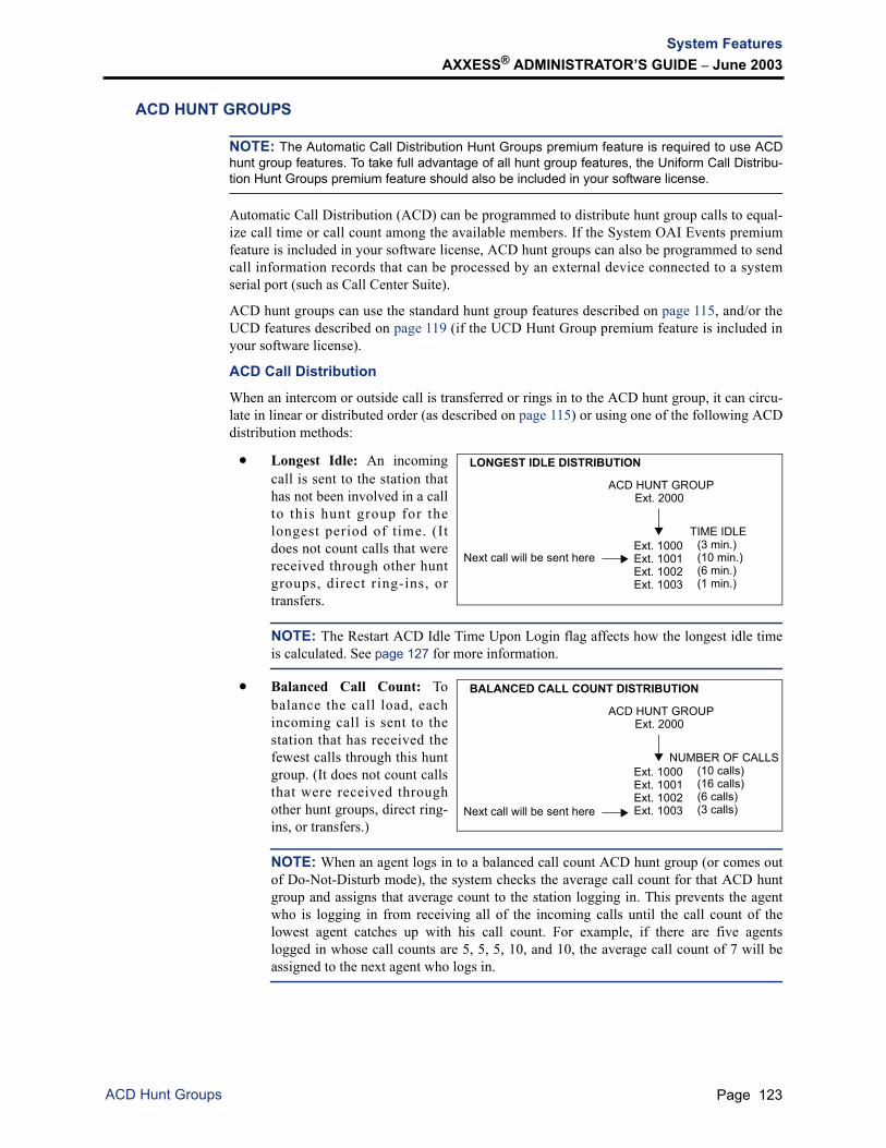
System FeaturesAXXESS® ADMINISTRATOR’S GUIDE – June 2003
ACD HUNT GROUPS
NOTE: The Automatic Call Distribution Hunt Groups premium feature is required to use ACDhunt group features. To take full advantage of all hunt group features, the Uniform Call Distribu-tion Hunt Groups premium feature should also be included in your software license.
Automatic Call Distribution (ACD) can be programmed to distribute hunt group calls to equal-ize call time or call count among the available members. If the System OAI Events premiumfeature is included in your software license, ACD hunt groups can also be programmed to sendcall information records that can be processed by an external device connected to a systemserial port (such as Call Center Suite).
ACD hunt groups can use the standard hunt group features described on page 115, and/or theUCD features described on page 119 (if the UCD Hunt Group premium feature is included inyour software license).
ACD Call Distribution
When an intercom or outside call is transferred or rings in to the ACD hunt group, it can circu-late in linear or distributed order (as described on page 115) or using one of the following ACDdistribution methods:
• Longest Idle: An incomingcall is sent to the station thathas not been involved in a callto this hunt group for thelongest period of time. (Itdoes not count calls that werereceived through other huntgroups, direct ring-ins, ortransfers.
NOTE: The Restart ACD Idle Time Upon Login flag affects how the longest idle timeis calculated. See page 127 for more information.
• Balanced Call Count: Tobalance the call load, eachincoming call is sent to thestation that has received thefewest calls through this huntgroup. (It does not count callsthat were received throughother hunt groups, direct ring-ins, or transfers.)
NOTE: When an agent logs in to a balanced call count ACD hunt group (or comes outof Do-Not-Disturb mode), the system checks the average call count for that ACD huntgroup and assigns that average count to the station logging in. This prevents the agentwho is logging in from receiving all of the incoming calls until the call count of thelowest agent catches up with his call count. For example, if there are five agentslogged in whose call counts are 5, 5, 5, 10, and 10, the average call count of 7 will beassigned to the next agent who logs in.
LONGEST IDLE DISTRIBUTION
ACD HUNT GROUPExt. 2000
Ext. 1000Ext. 1001Ext. 1002Ext. 1003
Next call will be sent here
TIME IDLE(3 min.)(10 min.)(6 min.)(1 min.)
BALANCED CALL COUNT DISTRIBUTION
ACD HUNT GROUPExt. 2000
Ext. 1000Ext. 1001Ext. 1002Ext. 1003Next call will be sent here
NUMBER OF CALLS(10 calls)(16 calls)(6 calls)(3 calls)
Page 123ACD Hunt Groups

System FeaturesAXXESS® ADMINISTRATOR’S GUIDE – June 2003
If an extension list is included in an ACD hunt group set for Longest Idle or Balanced CallCount distribution, it will treat each station in the extension list as a separate agent; it will notring all of the stations on the list at once. If the hunt group is set for linear or distributed order,a call will ring at all stations on an extension list at once when the call reaches that point in thehunt group list.
ACD Agent IDs
ACD hunt group members are referred to as “agents.” Agents log in to the ACD hunt group toreceive calls and log out to halt ACD hunt group calls. An ACD hunt group can be pro-grammed to circulate calls to agents in two ways:
• Agent IDs: If the hunt group is programmed to use ACD Agent IDs, each agent isassigned an Agent ID number which he or she enters during the login procedure(described below). The hunt group calls are routed to logged in agents, according totheir Agent ID number instead of their station extension. Because the Agent ID is notassociated with any station extension, the agent can use any station in the system to login and does not have to use the same station every time.
• Members: If the hunt group is not programmed to use Agent IDs, it will have a list ofstations and will send calls to the stations where agents are logged in.
NOTE: For optimum system performance, there should not be more than 1000 AgentIDs in any hunt group and no more than 2000 Agent ID entries in all hunt groups com-bined.
ACD Agent IDs can be included in Extension Lists which allow several ACD Agents toreceive a call at once.
When a call camps on to an ACD hunt group that uses Agent IDs, only the agents currentlylogged in to the hunt group will receive camp-on indications. ACD hunt group supervisors willreceive visual camp-on displays if they are programmed as members of the hunt group andhave the ACD Agent Logout feature enabled.
Page 124 ACD Hunt Groups

System FeaturesAXXESS® ADMINISTRATOR’S GUIDE – June 2003
ACD Agent Login/Logout
ACD hunt g roup members a rereferred to as “agents.” Agents canlog in to and out of the ACD huntgroup at any time. While logged in,the agent will receive calls throughthe ACD hunt group. When the agentis logged out, calls to that ACD huntgroup will bypass the station. (TheHunt Group Remove/Replace fea-ture, described on page 118, does nothave any effect on ACD hunt groupcalls when entered by an ACD agent.However, placing the agent’s stationin Do-Not-Disturb will halt all ACDand non-ACD hunt group calls.)
There are three feature codes that can be used for logging in to and out of the ACD huntgroups: ACD Agent Login, ACD Agent Logout, and ACD Agent Login/Logout. The first twoperform only one operation. The third (Login/Logout) is a toggle feature code that logs the sta-tion in or out of all associated ACD hunt groups at once. If the toggle feature code is pro-grammed in a user-programmable button with a lamp, the lamp will be lit when the agent islogged in to an ACD hunt group and available to receive calls, and it will be unlit when theagent is logged out.
TO LOG OUT OF ALL OF YOUR ACD HUNT GROUPS AT ONCE USING THE LOGIN/LOGOUT FEATURECODE:
While on or off hook (single-line users must lift the handset), enter the ACD AgentLogin/Logout feature code (328). The display shows AGENT LOGGED OUT OFALL ACDS, and you hear a confirmation tone. Hang up if off hook.
TO LOG IN TO ALL OF YOUR ACD HUNT GROUPS AT ONCE USING THE LOGIN/LOGOUT FEATURECODE:
1. While on or off hook (single-line users must lift the handset), enter the ACD AgentLogin/Logout feature code (328). If you were already logged in, the display showsAGENT LOGGED OUT OF ALL ACDS, and you hear a confirmation tone. If youwere not logged in, continue to the next step.
2. The display shows AGENT LOGIN AGENT ID. Do one of the following:
— To log in to all ACD hunt groups for which you have an Agent ID: Enter yourAgent ID. The display shows AGENT LOGGED INTO ALL ACDS. You arelogged into only the ACD hunt group(s) that use the Agent ID that you entered.Hang up if off hook. If another agent is already logged in at this station, you hearreorder tones, and the display shows DIFFERENT AGENT ID ALREADY USED.You must have the other agent log out before you can use that station.
— To log in to all of your ACD hunt groups that do not use Agent IDs: Press .The display shows AGENT LOGGED INTO ALL ACDS. You are logged into onlythe ACD hunt group(s) that do not use Agent IDs. Hang up if off hook.
HUNT GROUP
ID 2370
AGENT ID IN UCD/ACD HUNT GROUPHUNT GROUP
Ext. 2000
ANNOUNCEMENTSTATION
OVERFLOWSTATION
Ext. 1222
Agent IDcan be logged
in or outRECALL STATION
#
Page 125ACD Hunt Groups

System FeaturesAXXESS® ADMINISTRATOR’S GUIDE – June 2003
TO LOG IN TO ONE OR MORE HUNT GROUPS USING THE ACD AGENT LOGIN FEATURE CODE:
1. While on or off hook (single-line users must lift the handset), enter the ACD AgentLogin feature code (326). The display shows AGENT LOGIN ACD NUMBER.
2. Enter the pilot number of the desired ACD hunt group. (Or, you can press to log into several ACD hunt groups at once.)
If you entered an invalid hunt group number, the display shows NOT AN ACD HUNTGROUP, and you hear reorder tones.
3. The display shows AGENT LOGIN AGENT ID. Then do one of the following:
— To log in to ACD hunt group(s) using Agent IDs: Enter your Agent ID. The dis-play shows AGENT LOGGED INTO ALL ACDS. You are logged into only theACD hunt group(s) that you requested in step 2 that use the Agent ID that youentered in this step. If another Agent ID is already logged in at this station, youhear reorder tones and the display shows DIFFERENT AGENT ID ALREADYUSED. You must have the other agent log out before you can use that station.
— To log in to ACD hunt group(s) that do not use Agent IDs: Press . The dis-play shows AGENT LOGGED INTO ALL ACDS. You are logged into only theACD hunt group(s) that you requested in step 2 that do not use Agent IDs.
If you were already logged in, the display shows ALREADY LOGGED INTO (huntgroup).
If you are not a member of the entered hunt group, the display shows NOT ANAGENT IN THIS HUNT GROUP, and you hear reorder tones. Start over.
4. If off hook, hang up. Repeat this procedure to log in to additional ACD groups, if nec-essary.
TO LOG OUT OF AN ACD HUNT GROUP:
1. While on or off hook, enter the ACD Agent Logout feature code (327). One of the fol-lowing will occur:
If you were logged in to only one hunt group, you hear a confirmation tone, and thedisplay shows AGENT LOGGED OUT OF (hunt group). The procedure is complete.Hang up if you were off hook.
If you were logged in to more than one hunt group, you hear a confirmation tone, andthe display shows AGENT LOGOUT ACD NUMBER. Go to the next step.
If you were not logged in to any hunt group, the display shows NOT LOGGED INTOANY ACD GROUP, and you hear reorder tone.
2. Dial the pilot number of the desired ACD hunt group or press pound ( ) to log out ofall of your ACD hunt groups. You hear a confirmation tone, and the display showsAGENT LOGGED OUT OF (hunt group).
If you were not logged in to the hunt group number that you entered, the display showsNOT LOGGED INTO (hunt group). Start over.
3. If off hook, hang up.
#
#
#
Page 126 ACD Hunt Groups

System FeaturesAXXESS® ADMINISTRATOR’S GUIDE – June 2003
Restart ACD Idle Time Upon Login Flag
The Restart ACD Idle Time Upon Login flag determines where an agent is placed in a longestidle queue when he or she logs back in to a hunt group. When enabled, the agent’s idle time isreset to zero whenever he or she logs in (i.e., that agent will be least likely to receive the nextdistributed call). If disabled, the agent’s idle time includes the time the agent was logged out ofthe hunt group (i.e., that agent will be most likely to receive the next distributed call). Bydefault, this flag is disabled.
This flag is programmable for each individual hunt group.
ACD Agent Wrap-Up Timer
Each time an agent ends an ACD hunt group call, the station goes into “wrap-up” mode, andthe ACD Wrap-Up Duration timer is started. Until that timer expires, the agent will not receiveanother call through any ACD hunt group. (However, the agent can receive non-ACD huntgroup calls, direct ring-in calls, and transfers.)
The range of the ACD Wrap-Up Duration timer is 1 to 65535 seconds. The default value is 15seconds. It is programmed individually for each ACD hunt group.
If an agent wishes to terminate the wrap-up mode before the timer expires, he or she can usethe following procedure.
TO TERMINATE ACD AGENT WRAP-UP:
While on or off hook (single-line users must lift the handset), enter the ACD Wrap-UpTerminate feature code (329). The display shows ACD WRAP-UP TERMINATED. (Ifyou were not logged in to an ACD hunt group, the display shows CANNOT ACCESSRESERVED FEATURE.)
Wrap-Up Mode for Holding ACD Calls
There is a system flag called “Wrap-Up Mode For Holding ACD Calls.” If enabled, it placesan ACD agent’s station in wrap-up mode when an ACD call is placed on hold. (However, theACD Wrap-Up Duration timer is not activated.) This prevents the agent from receiving addi-tional ACD hunt group calls after he or she places an ACD call on hold while the station isidle. (The station can still receive non-ACD calls, as usual.) If the flag is disabled, the agentwill be available to receive additional ACD calls as soon as an ACD call is placed on hold. Inthe default state, this flag is disabled.
This flag applies to any type of hold, including individual, system, transfer, and conference-wait hold. If the call is terminated or if it is reverse transferred by another station, the ACDagent’s station will be made available to receive incoming ACD calls.
If the agent wishes to terminate the wrap-up mode while an ACD call is on hold, he or she canuse the procedure described in the previous section.
ACD Agent ID Automatic Connect Flag
When the ACD Agent ID flag is enabled, and the agent is using a headset, ACD hunt groupcalls will automatically be connected following a short ring burst. (This feature will not work ifthe agent is not using a headset.)
When the ACD agent logs in or removes the station from Do-Not-Disturb mode, the first callwill ring until the ACD agent answers it. However, every time an ACD hunt group call isreceived after the first call, the agent will hear the ring burst in the headset and the call will beautomatically connected.
This flag overrides the station’s Transfer-To-Connect station flag, which is disabled by default.
Page 127ACD Hunt Groups

System FeaturesAXXESS® ADMINISTRATOR’S GUIDE – June 2003
Group Call Pick-Up
When the Group Call Pick-Up feature is enabled, a call ringing in to a hunt group or one of itsstations can be picked up at any other station. Users can enter the Reverse Transfer featurecode (4) and dial a hunt group’s pilot number to pick up a call that is ringing in to the huntgroup’s pilot number or to any station within that hunt group.
The system follows the priority list shown below to determine which call is picked up. Thesystem follows the hunt group list (always beginning with the first station on the list) to checkeach station in the hunt group and then the overflow station for one type of call at a time. Ifthere is more than one call of the same type at the selected station, the call that was received bythe station first is picked up. Holding calls and queue callbacks cannot be picked up.
1. Calls to the hunt group pilot number
2. CO calls
a. Direct ring-in calls
b. Transferred calls
c. Recalls
d. Camped-on calls
3. IC calls
a. Direct ring-in calls
b. Transferred calls
c. Recalls
d. Camped-on calls
NOTE: Group Call Pick-up can only retrieve calls from stations that are currently logged in tothe hunt group. You cannot use this feature to pick up calls from members who have logged outusing the Hunt Group Remove feature code. Also, Group Call Pick-up cannot be used on ACDHunt Groups that use Agent IDs. It can only be used on hunt groups that use lists of extensions.If the ACD Hunt Group flag is enabled, the Group Call Pick-up flag will be dimmed.
To pick up a call that is ringing at a hunt group:
1. Lift the handset, and/or enter the Reverse Transfer feature code (4). You hear a singleprogress tone.
2. Dial the pilot number of the hunt group where the call is ringing.
Inter-Tel Phones: If the system is programmed for direct connection of reverse trans-ferred calls, you are immediately connected. If not, press the flashing CALL, individ-ual trunk, or button.
Single-Line Sets: You are automatically connected.
IC
Page 128 ACD Hunt Groups

System FeaturesAXXESS® ADMINISTRATOR’S GUIDE – June 2003
ACD HUNT GROUPS SPAN NODESThere is a premium feature called Remote Automatic Call Distribution Hunt Groups. It allowsACD hunt groups to span nodes. Node-spanning ACD hunt groups can have either members orACD Agent IDs.
• Members: ACD hunt group members may include off-node-phones, off-node singlelines, and Hunt Group Member extension lists.
• ACD Agent IDs: Unlike members, there are no off-node Agent IDs. Agent IDs areconsidered global throughout all nodes in which the Agent exists. This means that ifyou create Agent ID 100 on one node, you must also create Agent ID 100 on all othernodes that have a station that a user may wish to login to the hunt group using that ID.
The Remote Automatic Call Distribution Hunt Groups premium feature must be included inthe software license where the hunt group resides as well as any node that wishes to have userslogin to the node-spanning hunt group. The ACD Hunt Groups premium feature is alsorequired. Because of this fact, there are several cases that must be considered. The followingtable shows the different displays and results for logging into and out of ACD hunt groups withthe different combinations of the premium feature and the ACD Hunt Group enabled/disabled.
Database Programming
• ACD hunt groups have options allowing the addition of phone off-node devices, singleline off-node devices, and hunt group member extension lists containing local or off-node stations or both.
• If the Remote Call Distribution Hunt Groups premium feature is not included in thenode’s software license, the off-node options will not appear in the list when program-ming members for ACD hunt groups.
STN NODE
HUNT GRP
NODELOGIN DISPLAY LOGIN RESULT LOGIN “ALL”
DISPLAY LOGIN “ALL” RESULT
Yes Yes AGENT LOGGED INTO HUNT GROUP XXXX
Agent logged into hunt group.
AGENT LOGGED INTO ALL ACDS
Agent logged into all local and remote groups.
Yes No CANNOT ACCESS RESERVED FEATURE
Agent not logged into group.
AGENT LOGGED INTO ALL ACDS
Agent logged into all local hunt groups, but not remote where fea-ture disabled.
No Yes CANNOT ACCESS RESERVED FEATURE
Agent not logged into group.
AGENT LOGGED INTO ALL ACDS
Agent logged into all local, but no remote groups.
No No CANNOT ACCESS RESERVED FEATURE
Agent not logged into group.
AGENT LOGGED INTO ALL ACDS
Agent logged into all local, but no remote groups.
Page 129ACD Hunt Groups Span Nodes

System FeaturesAXXESS® ADMINISTRATOR’S GUIDE – June 2003
Operational Changes
• The Station Monitor feature remains limited to a single node. Members who are loggedin to a remote node or who are logged in to the supervisor’s node from a remote nodecannot be monitored.
• Hunt groups with remote members rely on network links between nodes. Node avail-ability and software version compatibility affect hunt group log-in procedures as fol-lows:
— Hunt group members attempting to log in to all hunt groups will be logged in toonly those hunt groups on nodes that are reachable. The display on the user devicewill only indicate log in results for reachable nodes.
— Members logging out of all hunt groups will be logged out of groups on reachablenodes immediately and will automatically be logged out of groups on unreachablenodes as soon as the link to the node is restored. The phone will display MES-SAGE PENDING in this case.
— When users attempt to log in to a remote hunt group on a node running an earlierversion of System software, the phone display in version 5.3 or later will showNOT AN ACD HUNT GROUP.
— If users on a node running an earlier version of system software try to log into ahunt group on a node running version 5.3 or later, the display will show the mes-sage NOT AN AGENT IN THIS ACD GROUP.
• The ACD Wrap-Up functions perform as in previous versions with the exception of pri-ority. Due to timing issues involved in sending messages across the network, the fol-lowing prioritization method is used for hunt groups with remote members:
— The first criterion is priority level. The hunt group with the highest priority gets theavailable agent first.
— In the event of a tie in priority, hunt groups located locally take priority over thoselocated on remote nodes.
— In cases where ties in priority occur within the local node, the hunt group with thelongest camped on call will receive the available agent.
— Given off-node ties in priority, the first hunt group to camp on will receive theavailable agent.
Page 130 ACD Hunt Groups Span Nodes
System FeaturesAXXESS® ADMINISTRATOR’S GUIDE – June 2003
Maintenance of Node-Spanning Hunt Groups
• Deletion of ACD Agents is different in version 5.3 or later because agents must bedefined globally. In previous versions, deletion of an agent resulted in removal of theagent from any hunt groups in which the agent was a member and also logged the agentout. With node-spanning hunt groups, deleting an agent from a hunt group can be donefrom the node on which the hunt group resides or from a remote node.
— If an agent is deleted on the node containing hunt group(s) of which he is a mem-ber, then the agent is removed from all hunt group(s) on that node and is loggedout.
— If the agent is deleted from a remote node, the agent is logged off from that node,but remains a member of any hunt group(s) located on other nodes.
• Deletion of ACD Hunt Groups in previous versions resulted in all member stationsbeing logged out. In version 5.3 or later, this will apply to off-node, logged-in stationsalso. When the hunt group is deleted, all remotely logged-in stations will be logged out.
• If the extension number of an ACD Hunt Group is changed, any local or remote stationsthat are logged in will reflect the change. If links are down at the time of the change,remote nodes will not receive the change and an import/export process will be neces-sary to update the information on the affected nodes.
• Removing an Agent ID from a hunt group agent list logs out any station, local orremote, that is logged in to that hunt group using that Agent ID.
• With the node-spanning features of ACD hunt groups, changing Agent IDs can be donefrom two possible locations: on the node where the group resides or on a node wherethe logged-in station resides.
— When changing an Agent ID on the node where the hunt group resides, theremotely logged-in station using that Agent ID will be logged out even though theAgent ID still exists on the remote node. The hunt group will then contain the newAgent ID in its removed list, making the new Agent ID available for log-in use.
— When changing an Agent ID on the node on which the logged-in station resides (anode remote from the hunt group), the remote member will be logged out and theold Agent ID will no longer exist on that node. The hunt group on the original nodewill contain the old Agent ID in its removed list, because this ID still exists on thatnode.
• During a database restore on a node containing ACD hunt groups that use Agents IDs,all Agents IDs are placed into each hunt group’s removed list. All stations will belogged out during the restore.
• When the extension number of a logged-in station is changed, the new extension will belogged in with the same Agent ID and will not be disconnected. This applies to stationslogged in both remotely and locally.
Page 131ACD Hunt Groups Span Nodes
System FeaturesAXXESS® ADMINISTRATOR’S GUIDE – June 2003
TRUNK FEATURES
This section explains the trunk functions and programmable features.
CALLER ID, DNIS, AND ANI
NOTE: The Advanced CO Interfaces premium feature is required to use the following features.
The system supports Caller ID, ANI, and DNIS. These features provide information about thesource of the call.
• Caller ID: Caller ID information gives the caller’s telephone number and/or name.
• ANI: Automatic Numbering Identification (ANI) information identifies the caller’stelephone number. The system receives a specified number of digits.
• *ANI*: This is a form of ANI that does not have a specified number of digits. The sys-tem receives a star (*) before the ANI digits to signal the beginning of the caller’s tele-phone number. Then there is another star after the digits to signal the end of the ANIinformation.
• DNIS: Dialed Number Identification Service (DNIS) identifies the number that wasdialed to reach your location. The system receives a base number and a specified num-ber of digits that identify the dialed number.
• *DNIS*: This is a form of DNIS that does not have a specified number of digits. Thesystem receives a star (*) before the DNIS digits to signal the beginning of the dialednumber. Then there is another star after the digits to signal the end of the DNIS infor-mation.
• *ANI*DNIS*: This is a two-stage address service that provides both the caller’s tele-phone number and the dialed number. It combines the *ANI* and the *DNIS* featuresdescribed above.
NOTE REGARDING TRUNK SECURITY
While this system is designed to be reasonably secure against CO trunk misuse by outsidecallers, there is no implied warranty that it is not vulnerable to unauthorized intrusions andtoll fraud. If the central office does not provide supervision it will not disconnect the callwhen one party hangs up; it is possible for a caller to remain connected to a CO trunk cir-cuit. If this happens, and the caller begins dialing, the call could be placed through the sys-tem and would then be billed to the system’s owner. The system cannot check this type ofcall for toll restriction and may not register the call in SMDR. This problem could arisewhen a call is connected to a station or when a call is in an unsupervised conference.
Page 132 Trunk Features

System FeaturesAXXESS® ADMINISTRATOR’S GUIDE – June 2003
INTER-TEL PHONE DISPLAYS
Whether call information appears on the Inter-Tel phone display and what information appears,is determined by station flags in the database. The flags are:
• Expanded CO Call Information On Displays: This station flag determines whethercall information (trunk name or call information) is displayed at the phone. If it isenabled, the Outside Call Party Information Has Priority flag (described below) deter-mines what is displayed. If it is disabled, the programmed trunk group username willappear on the display. In the default state, this flag is enabled.
• Outside Party Call information Has Priority: If the Expanded CO Call Informationflag is enabled (as described above), this flag determines what information is displayedat the phone. If enabled, any call that is received on a trunk that provides outside callinformation (for example, Caller ID or ANI), will be identified on the phone’s displaywith the call information. If disabled, the display will show the DID or DNIS informa-tion for the call (if available). In the default state, is it enabled.
• Display Outside Name: If the Display Outside Name station flag is enabled, the phoneuser can switch between the outside party name and number when connected to a COcall with outside party information. The phone user enters the Display Outside PartyName On/Off feature code (379). In addition, the enhanced ring-in displays will providethe user with more information such as both Caller ID name and number if available, ortell the user if a Caller ID number is blocked or out-of-area. This is a station flag thatapplies to Inter-Tel phones only. In the default state, this flag is enabled.
The system will provide the user with advanced displays for direct ring-in calls, if the stationhas “Expanded CO Call Information On Displays” and “Outside Party Call Information HasPriority” station flags enabled (by default they are enabled).
A typical direct ring in display would look like the following: “TRNK GRP 1 RINGING IN.”However, with the enhanced displays, the system will attempt to display the name of the out-side caller on line 1 and the number of the outside caller on line 2.
When a CO call rings into the system, the system uses the following criteria to determine thename that will appear on the display phones. The criteria are listed from highest priority tolowest priority.
Display Line 1
The following criteria are used to display the name on the top line of the ring-in display. Thisassumes that all of the necessary station flags are properly set and usernames are correctlyfilled in or left blank (at the programmer’s discretion) for Call Routing Tables and TrunkGroup Names.
1. Outside Party Name provided by the Desktop Application, if available.
2. Outside Party Name provided by Caller ID, if enabled at the system-wide flag level. 3. Outside Party Name provided by system speed-dial. If the collected number matches a
number in a speed-dial bin, the system uses the name of the corresponding speed-dialbin.
4. Outside Party Number provided by the Desktop Application. 5. Outside Party Number provided by Caller ID, if enabled at the system-wide flag level. 6. Outside Party Number provided by ANI service, if enabled at the system-wide flag
level. 7. Call Routing Table Name, if the name is not blank. 8. Trunk Group Name, if the name is not blank. 9. Default Trunk Group Name (TG XXXXX).
Page 133Inter-Tel Phone Displays
System FeaturesAXXESS® ADMINISTRATOR’S GUIDE – June 2003
Display Line 2
The following criteria are used to display the number on the bottom line of the ring-in display.This assumes that all of the necessary flags are properly set.
1. Outside Party Number provided by the Desktop Application, if available.
2. Outside Party Number provided by Caller ID, if enabled at the system-wide flag level.
3. Outside Party Number provided by ANI service, if enabled at the system-wide flaglevel.
4. Number Absence Reason, such as Caller ID “OUT-OF-AREA” or “PRIVATE”(blocked) message.
5. RINGING IN display.
ANI and Caller ID information is also sent to the voice mail application to provide the caller’stelephone number as part of the message envelope.
OUTGOING-ACCESS, ALLOWED-ANSWER, AND RING-IN ASSIGNMENTS
Each trunk group has programmed lists of stations for outgoing-access, allowed-answer, andring-in assignments for day and night modes.
• Outgoing-access assignment for a particular trunk group or node trunk group permitsthe station user to place calls using trunks in that trunk group. Each station has a defaultoutgoing access code programmed in the database. When the user presses the
button, presses an idle Call button, or enters the Outgoing Call feature code(8), the system automatically selects an outgoing trunk.
NOTE: Because the network does not allow users to directly access trunks on othernodes, each trunk group’s Outgoing Access can contain only stations on the local node.(Users must use ARS to access trunks on other nodes.)
• Allowed-answer access to a particular trunk group permits the station user to answerincoming calls on the trunks in that trunk group (even if the station does not have ring-in assignment for that trunk group). Stations cannot have allowed-answer assignmentfor trunk groups on other nodes. On Inter-Tel phones, the individual trunk buttonflashes (if one exists) to indicate the ringing call. If a station is programmed withallowed-answer access only (no ring-in) for a trunk group, direct ring-in calls on thattrunk group can be answered by entering the Automatic Trunk Answer feature code(350) or pressing the flashing individual trunk button.
• Ring-in assignment for a particular trunk group can be assigned to one or more stations,extension lists, or Voice Processor applications; to a hunt group; to DISA; or to a callrouting table. A trunk can ring in to a station or Voice Processor application on anothernode. The ring in destination(s) for the trunk group will receive direct ring-in calls ontrunks in that trunk group. On Inter-Tel phones with ring in, the individual trunk or Callbutton flashes, and the display indicates a ringing call. Allowed answer for the trunkgroup is automatically assigned to a station with ring in.
When Inter-Tel phones have outgoing-access or ring-in assignments, the associated individualtrunk buttons show the status of their trunks.
OUTGOING
Page 134 Outgoing-Access, Allowed-Answer, and Ring-In Assignments

System FeaturesAXXESS® ADMINISTRATOR’S GUIDE – June 2003
Stations that do not appear on any of the lists cannot place or directly receive outside calls;they are limited to intercom calls, conferences, transferred calls, and retrieving calls on systemhold. (A call on system hold can only be picked up at the station that placed it on hold or at astation that has an individual trunk button and has allowed-answer and/or outgoing access forthat trunk.)
A private trunk group (with one or more trunks) can be established by programming outgoing-access, ring-in, and allowed-answer permission for the trunk group to only one station.
ANSWER FEATURE CODE
For calls that are ringing or holding at the station, the user may enter the Answer feature code(351) or press the button. When more than one call is ringing or holding, the fol-lowing priority list determines which call is answered first:
• Ringing calls (ring ins, recalls, callbacks, or transfers) are answered in the order theywere received.
• Calls on individual hold are answered in the order they were placed on hold.
AUTOMATIC ROUTE SELECTION (ARS)
NOTE: The Automatic Route Selection premium feature is required to use ARS.
ARS is a money-saving feature that allows the system to be programmed to select the leastexpensive route for placing outgoing calls. It can be used for placing outgoing calls and trans-ferring or forwarding calls to outside telephone numbers. Stations can be restricted to usingonly ARS for placing outgoing calls. Also, because users do not have direct access to trunks onother nodes, ARS is the only way users can place calls using the other nodes’ trunks.ARS is programmed using route groups and facility groups.
• Route Groups: A route group contains dialing patterns and facility groups. — The dialing patterns are used to determine the calls that will be routed through the
route group. For example, the default dial pattern for Route Group 1 is N+ (anynumber of digits beginning with digit 2-9). If a number is dialed that begins with 1,it will not be routed through this route group.
— Each route group has an ordered list of facility groups that contains lists of localtrunk groups and/or nodes. There can be 100 facility groups in the system. Thefacility groups should be programmed so that the least-expensive route is checkedand, if available, is selected first. If the least-expensive facility group is not avail-able, the system checks the other groups in the list until it finds an available trunk.
• Facility Groups: A facility group contains trunk group/node lists and dial rules.— The trunks can include local trunk groups or nodes.
— The dial rules tell the system what to dial. The system can have up to 32 dial rules,26 of which are programmable. Each facility group can use up to 32 dial rules. Forexample, if the selected route group requires that the number contain “1” but noarea code, the dial rules include the 1 and drop the area code. The modified tele-phone number can contain up to 32 digits. (If SMDR is enabled, the modified tele-phone number, not the digits dialed, will appear in the SMDR call record.) Whenprogramming ARS, you can use preset dial rules or create new dial rules that addup to 16 digits each. The pre-programmed dial rules are:
Dial Rule #1 – Echo Equal Access: This non-programmable dial rule includes theequal access digits (10XXX or 101XXXX) in the number, if dialed.
ANSWER
Page 135Answer Feature Code

System FeaturesAXXESS® ADMINISTRATOR’S GUIDE – June 2003
Dial Rule #2 – Echo Toll Field: The toll field (1, 0, 01, or 011) is included in thenumber, if dialed. This dial rule is non-programmable.
Dial Rule #3 – Echo 3 Digits After Toll Field: With this non-programmable dialrule, the three digits after the toll field are included in the number. (These digits areusually the area code or country code.)
Dial Rule #4 – Echo Local Address: This non-programmable dial rule allows ARSto dial the telephone number that was dialed by the station user.
Dial Rule #5 – Add Account Code: This non-programmable dial rule causes thesystem to dial the account code that is associated with the call, when it is available.The account code can be entered using any of the account code types, including AllCalls Following, as long as the system receives the account code before the end ofdialing. (To use an optional account code, the code must be entered before thenumber is dialed.)
Dial Rule #6 – Add Extension Number: This non-programmable dial rule tells thesystem to include the extension number of the station or Voice Processor applica-tion that is being used to place the call.
Dial Rule #7 – Add #: This dial rule adds a pound (#) to the number dialed. Thisdial rule can be programmed.
When ARS is selected, the user dials the number (including the area code, if needed), and thesystem does the following:
1. Checks the dialed number and matches the dialing pattern to a route group: Thesystem checks the route groups in numerical order and selects the first group thatapplies to the dialing pattern of the number that was dialed.
NOTE: If the Emergency Call feature is programmed to use ARS, the emergency callswill always go through Route Group 1, regardless of route group programming.
2. Selects a facility group: If all of the trunks are busy, and the station is enabled for ARScamp on, the call will camp on to the facility group until a trunk is available.
3. Checks for toll restrictions and outgoing access: Before the number is modified bythe facility group’s dial rules, the system checks the station toll restrictions and outgo-ing access to determine whether the call is allowed. (All calls placed using ARS are tollrestricted, regardless of whether the selected trunk is subject to toll restriction. How-ever, Emergency Call feature calls are never toll restricted.) If allowed, the system con-tinues to the next step. If not allowed, the system sends reorder tones, and the call is notplaced.
4. Adds or deletes digits according to the facility group chosen: Each facility group hasa programmed set of dial rules that tells the system what to dial. For example, if theselected route group requires that the number contain “1” but no area code, the dialrules include the 1 and drop the area code.
5. Dials the modified telephone number: If the number is allowed, the system seizes anidle trunk in one of the selected trunk groups, waits for the Dialing Wait After Connecttimer to expire, and then dials the number.
Page 136 Automatic Route Selection (ARS)
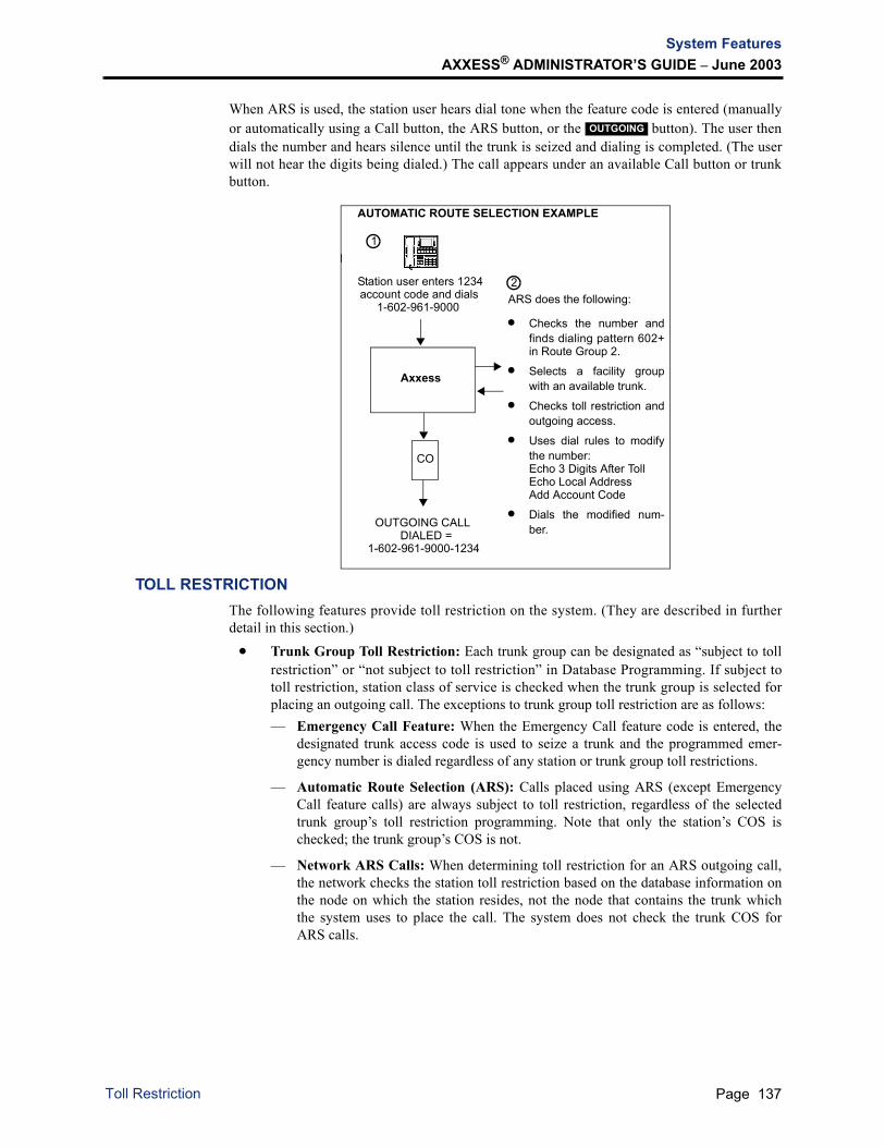
System FeaturesAXXESS® ADMINISTRATOR’S GUIDE – June 2003
When ARS is used, the station user hears dial tone when the feature code is entered (manuallyor automatically using a Call button, the ARS button, or the button). The user thendials the number and hears silence until the trunk is seized and dialing is completed. (The userwill not hear the digits being dialed.) The call appears under an available Call button or trunkbutton.
TOLL RESTRICTIONThe following features provide toll restriction on the system. (They are described in furtherdetail in this section.)
• Trunk Group Toll Restriction: Each trunk group can be designated as “subject to tollrestriction” or “not subject to toll restriction” in Database Programming. If subject totoll restriction, station class of service is checked when the trunk group is selected forplacing an outgoing call. The exceptions to trunk group toll restriction are as follows:— Emergency Call Feature: When the Emergency Call feature code is entered, the
designated trunk access code is used to seize a trunk and the programmed emer-gency number is dialed regardless of any station or trunk group toll restrictions.
— Automatic Route Selection (ARS): Calls placed using ARS (except EmergencyCall feature calls) are always subject to toll restriction, regardless of the selectedtrunk group’s toll restriction programming. Note that only the station’s COS ischecked; the trunk group’s COS is not.
— Network ARS Calls: When determining toll restriction for an ARS outgoing call,the network checks the station toll restriction based on the database information onthe node on which the station resides, not the node that contains the trunk whichthe system uses to place the call. The system does not check the trunk COS forARS calls.
OUTGOING
AUTOMATIC ROUTE SELECTION EXAMPLE
Station user enters 1234account code and dials
1-602-961-9000
Axxess
CO
OUTGOING CALLDIALED =
1-602-961-9000-1234
ARS does the following:
• Checks the number andfinds dialing pattern 602+in Route Group 2.
• Selects a facility groupwith an available trunk.
• Checks toll restriction andoutgoing access.
• Uses dial rules to modifythe number:Echo 3 Digits After TollEcho Local AddressAdd Account Code
• Dials the modified num-ber.
11
2
Page 137Toll Restriction

System FeaturesAXXESS® ADMINISTRATOR’S GUIDE – June 2003
• Exemption From ARS-Only Restriction: Each trunk group may be designated as“exempt from automatic route selection (ARS) only.” If exempt, station users with theARS-Only class of service can select the trunk group directly.
• Absorbed Digits: Trunk groups that are subject to toll restriction can be programmedto “absorb” (ignore) the first digit(s) dialed. This allows the system to handle the dialeddigits just as they would be by the local telephone company or PBX to which the sys-tem is connected.
• Station And Trunk Group Classes Of Service: Each station and trunk group can beassigned one or more classes of service (COS) which can restrict or allow certain digitpatterns when an outside call is dialed. (Trunk group COS is not checked when ARS isused.)
CLASS OF SERVICE (COS)Each station and each trunk group that is “subject to toll restriction” is assigned toll restrictionclasses of service (COS) that restrict or allow certain dialing patterns on outside calls.The classes of service (COS) are programmed individually for stations, Voice Processor appli-cations, and trunk groups. There are separate COS designations for day and night modes. Astation or trunk group can be completely unrestricted or can have any combination of theclasses of service. The first nine COS designations (01-09) have default values. COS designations (10-16) do nothave default values and are blank. All of the classes of service are programmable. Each may bespecified as an “allowed” or “denied” class of service, dialing patterns can be programmed foreach, and each can be assigned to stations and trunk groups as needed.
Page 138 Class Of Service (COS)

System FeaturesAXXESS® ADMINISTRATOR’S GUIDE – June 2003
The default values of COS 01-09 are as follows.
System speed-dial numbers can be programmed to bypass COS restrictions on a system-widebasis. If the option is not enabled, all system speed-dial numbers are subject to toll restriction.
Because a condition may exist where a critical or life threatening situation needs to bereported, using the Emergency Call feature code will override all toll restrictions and trunkaccess programming.
COS NAME RESTRICTION
01 ARS Only (This is a station class of service only. It is not used for trunk groups. Also, the Automatic Route Selection premium feature is required.) Calls can only be placed using the Automatic Route Selection (ARS) feature. The user will hear reorder tones when attempting to place a call using any other method. A restricted user can still select individual trunks if the trunks are designated as “exempt from ARS Only” (as described on page 138), were transferred, were placed on hold, or are recalling or ringing. Trunk restriction determines which trunks in the ARS route group can be selected by the station or application.
02 Deny Area/Office
This restriction is divided into eight user groups to allow the use of varying area/office code restriction tables. This is useful for reducing restrictions for some of the stations, applications, or trunk groups while increasing restrictions for others. Each station, application, and trunk group is assigned a day mode and a night mode user group in Database Programming. Within each user group, area codes can be designated as restricted, allowed, or extended. Restricting an area code prevents users from placing calls to that area code. Allowing an area code allows all office codes within that area code. Designating an area code as extended allows the programmer to determine which office codes (up to 800) are allowed or restricted within that area code.
03 DenyOperator
Calls to operator numbers are restricted.
04 Deny Toll Access
Calls to numbers containing a toll string (defaults to 1) are restricted.
05 Deny International
Calls to international numbers are restricted.
06 Deny Equal Access
Calls that begin with equal access digits (10XXX or 101XXXX) are restricted.
07 Deny Local Calls
Calls to local numbers are restricted.
08 Denied Numbers
Calls to programmed “denied” numbers (defaults to 1900NXXXXXX+ and 976XXXX+) are restricted.
09 Allowed Numbers
Calls to programmed “allowed” numbers (defaults to 1800NXXXXXX+) are allowed, even if number also matches a dial pattern in a restricted class of service that is assigned to the station, application, or trunk group being used.
Page 139Class Of Service (COS)

System FeaturesAXXESS® ADMINISTRATOR’S GUIDE – June 2003
Note that if the trunk group is “not subject to toll restriction,” neither the trunk group or stationCOS is checked, unless the call was placed using ARS. All ARS calls are subject to station tollrestriction only.
EMERGENCY CALL FEATURE
The system will immediately allow access to local emergency facilities whenever a station userenters the Emergency Call feature code (defaults to 911). When activated, the Emergency Callfeature will select a trunk or route the call based on the device programming. The digit(s)required to call the local emergency services facility (defaults to 911) are then automaticallydialed. Because a condition may exist where a critical situation needs to be reported, this fea-ture will override all toll restrictions and trunk access programming.
In versions prior to 7.0, when a user dialed 911 at intercom dial tone, the system selected anidle trunk using the trunk access code programmed for this feature (defaults to Trunk Group 1)or an individual line code (direct trunk access). In versions 7.0 and later, however, the emer-gency extension is programmable on a per-station basis. In addition, Day/Night EmergencyOutgoing Access lists are provided to validate the extension making the emergency call. Whena user dials 911 at intercom or CO dial tone, emergency outgoing access is granted based onhow system programming and what the user dialed, as described below.
• If the user dials the emergency feature code from a station with a trunk or trunk groupprogrammed as the Emergency Extension, the Emergency Call feature routes the callbased on the station’s Emergency Extension. The trunk or trunk group does not validatethe station originating the emergency call against the trunk group’s Emergency Day/Night Outgoing Access List. An idle trunk is seized, and the system automatically dialsEmergency Number 1.
• If the user dials the emergency feature code from a station with ARS programmed as theEmergency Extension:
a. The Emergency Call feature routes the call based on the station’s EmergencyExtension.
b. The call is routed to Route Group 1.
c. The call tries the first facility group in Route Group 1.
d. The trunk group or node trunk group validates the station originating the emer-gency call against the group’s Emergency Day/Night Outgoing Access List.
e. If the call is denied, it tries the next member in the facility group. If each memberdenies the call, the call tries the next facility group in Route Group 1’s list.
If everything is denied due to Emergency Outgoing Access, the call is routed onceagain to Route Group 1. The call then tries the first facility group in Route Group1. The trunk group or node trunk group does not validate the station originating theemergency call against the group’s Emergency Day/Night Outgoing Access List. Ifno trunks are available, the call tries the next member in the facility group. If all ofthe members are unavailable, the call camps-on to Route Group 1 until a trunk isavailable.
NOTICEIt shall be the responsibility of the entity or person(s) completing installation and mainte-nance of hardware or software described herein to research, comply with and be responsi-ble for the specific governmental rules and regulations regarding Emergency OutgoingAccess (911) of the geographic location in which such functions are performed.
Page 140 Class Of Service (COS)

System FeaturesAXXESS® ADMINISTRATOR’S GUIDE – June 2003
• If the user accesses a trunk or trunk group and dials any Emergency Number (1-10), thetrunk or trunk group does not validate the station originating the emergency call againstthe trunk group’s Emergency Day/Night Outgoing Access List. An idle trunk is seized,and the system automatically dials the emergency number.
• If the user accesses ARS and dials any Emergency Number (1-10):
a. The call is routed to Route Group 1.
b. The call tries the first facility group in Route Group 1.
c. The trunk group or node trunk group validates the station originating the emer-gency call against the group’s Emergency Day/Night Outgoing Access List.
d. If the call is denied, the call tries the next member in the facility group. If eachmember denies the call, the call tries the next facility group in Route Group 1’s list.
If everything is denied due to Emergency Outgoing Access, the call is routed onceagain to Route Group 1. The call then tries the first facility group in Route Group1. The trunk group or node trunk group does not validate the station originating theemergency call against the group’s Emergency Day/Night Outgoing Access List. Ifno trunks are available, the call tries the next member in the facility group. If all ofthe members are unavailable, the call camps-on to Route Group 1 until a trunk isavailable.
NOTE: Inter-Tel highly recommends that only local trunks be installed and used foremergency trunk access and that only local trunks be programmed in Route Group 1.Programming a node in Route Group 1 may cause the system to access a trunk on aseparate node when ARS is used for emergency access. If this occurs, Emergency Out-going Access is no longer validated.
The system will allow the Dialing Wait After Connect timer to expire and will then dial thedigit string programmed in the database as the emergency number.
At the time the call is processed, a minor alarm will be generated by the system and sent to alladministrator stations. Also if the Message Print option is enabled, the alarm message is sent tothe designated output port.
EMERGENCY CALL FEATURE
AXXESS DATABASE:
Station userdials 911
EMERGENCY EXT. =TRUNK GROUP 1 (92001)
EMERGENCY No. = 911
CALL PLACEDTO 911
ALARM #11DISPLAYED
MESSAGE PRINTOUT,IF ENABLED
ORDIRECT TRUNK ACCESS
Page 141Class Of Service (COS)

System FeaturesAXXESS® ADMINISTRATOR’S GUIDE – June 2003
Emergency Outgoing Access Lists
As of version 7.0, the system supports two outgoing access lists called Emergency Day Outgo-ing Access and Emergency Night Outgoing Access. These lists, which are similar to the Day/Night Outgoing Access lists, are programmable for CO Trunk Groups and Node IP ConnectionGroups. These lists default to the Auto Extension List PP051: Auto: All Stations.
Ten Emergency Numbers
The system can store up to ten emergency numbers that are dialed when the Emergency Callfeature is used.
When the Emergency Call feature code (defaults to 911) is dialed at intercom dial tone, theEmergency Call feature will select a trunk (defaults to Trunk Group 1) and then automaticallydial Emergency Number 1. If a station user accesses a trunk or ARS and dials EmergencyNumbers 1-10, the dialed number will automatically override all toll restrictions and trunkaccess programming.
If the system is installed in an area where 911 service is not available, it is suggested that thenumber for the local police or fire department or the telephone company operator be substi-tuted.
If the database programmer renders this feature inoperative by removing all trunk access and/or by removing the dialed digit string, the database program will present a warning messageindicating that the feature has been disabled and requiring the programmer to acknowledge orchange this condition before being allowed to continue.
Like all other feature codes, the 911 feature code can be changed to another 1- to 5-digit code,if necessary, but it is not recommended.
An emergency number will be blocked if there are no trunks or emergency numbers programedin the database, or all trunks in a trunk group are busy.
If the Emergency Call feature is programmed to use ARS, route group 1 (local calls) will beused even if its dial patterns are reprogrammed.
Emergency calls, by default, use the first local trunk group and will not be sent using nodetrunk groups on other nodes. However, when ARS is used to place an emergency call, RouteGroup 1 is used even if it contains nodes. This means that the network can access a trunk on anode other than the user’s node if the user accesses ARS and dials the emergency number.Local trunks must be installed and used for emergency number trunk access and nodes shouldnot be used in Route Group 1. When a user places an emergency call, every administrator inthe network receives an emergency alarm.
Page 142 Class Of Service (COS)

System FeaturesAXXESS® ADMINISTRATOR’S GUIDE – June 2003
Calling Party Number Field
Each station can be programmed to send an identifying number when a call is placed. The“Calling Party Number field is located in Devices and Feature Codes - Stations - IndividualStation programming. This information is required for emergency 911 calls in some states. Youcan program any number up to 48 digits in the Calling Party Number field. However, checkwith your service provider to determine their specific requirements for this field. This numberwill be sent in the ISDN setup message in the Calling Party Number Information Element. Inaddition, the system will also send the extension number of the station in the Calling PartyNumber Subaddress Information Element. The CO should ignore this information element if itdoes not support it.
NOTE: There is no default number for this field. It is up to the programmer to supply the correctEmergency Calling Party Number for each station.
If an off-premises extension is used for dialing 911, the 911 operators will see Calling PartyNumber or the address of the location of the system, not the off-premises address. Off-pre-mises personnel should be prepared to give the correct address and other pertinent informationif it is not programmed as the Calling Party Number.
Page 143Class Of Service (COS)

System FeaturesAXXESS® ADMINISTRATOR’S GUIDE – June 2003
IP Devices and Local Loop Support
System software V7.0 and later supports IP-based solutions for providing local PublicSwitched Telephone Network (PSTN) connectivity using the IPRC card and a third-partyMedia Gateway Control Protocol (MGCP) gateway. The system requires software V7.0 andIPRC firmware V1.3. The firmware expands the support of 16 IP Phones/SLAs/SoftPhones toinclude Loop Start Adapters (LSAs). Support for IP-based local loop does not require PremiumFeatures.
Up to 16 ports of a Non-Networking IPRC can be programmed to be loop start adapter ports(MGCP gateway trunks). The IPRC statically maps Voice over IP resources on a one-to-one,non-blocking basis for each loop-start port within the MGCP device.
Inter-Tel currently supports the four-port FXO version of the AudioCodes™ MP-100 Gate-way Device. This device can be configured to support up to four loop-start line (FXO) ports.For details on the gateway device, see the latest version of the IP Devices Installation Manual.
NOTE: At the time of this publication, the testing of the AudioCodes™ MP-104 GatewayDevice was still in progress. Contact your sales representative for updated information on avail-able solutions.
When configured with an MGCP Gateway, you can program the system so that when 911 isdialed from an IP device, the calling name and number associated with the IP device, not thesystem, is sent to the 911 operators. See the latest version of the IP Devices Installation Man-ual for details.
NOTE: The MGCP gateway is intended to connect to the PSTN. Connecting the MGCP gate-way to single-line ports on other phone systems is currently not supported.
CAUTION
If an IP PhonePlus, Model 8660 IP Phone, or IP SLA user dials 911 from a remote locationand an MGCP gateway is not present and configured properly, the call will be placed fromwhere the telephone system is located. Because 911 services use caller ID to help locate thecaller, emergency service could be misdirected or delayed. Also, the 911 service contactedmay be local to the system, but not to the IP device. All IP device users should be alerted tothis situation and instructed to use a local telephone line for placing emergency calls if anMGCP gateway is not present and/or functioning properly. Also note that the IP device willnot function in the event of a power failure at either the local site or the system location.
Page 144 Class Of Service (COS)

System FeaturesAXXESS® ADMINISTRATOR’S GUIDE – June 2003
DAY AND NIGHT MODESThere are separate lists in the database for class-of-service, outgoing-access, allowed-answer,and ring-in assignments for day and night modes. When an administrator enters the Night Ringfeature code, the system uses the night mode lists. When the system is in day mode, the daylists are used. (Active calls are not affected when the mode is changed.)
Night mode also affects the night transfer relays on the Options Card (OPC). The relays areactivated when the system is placed in night mode.
Administrators can place any or all remote nodes into night mode or day mode. The defaultfeature code for Enable Network Night is 9861. The default feature code for Disable NetworkNight is 9862.
NOTE: The Night Ring On/Off feature code (9860) affects only the node on which the adminis-trator resides. See page 8 for a complete explanation of administrator features.
DIRECT INWARD SYSTEM ACCESS (DISA)DISA is a programmable feature that allows an outside party to dial into the system from anexternal DTMF telephone and then dial extension numbers, hunt group pilot numbers, and off-node device extensions. (DISA callers do not have access to outgoing trunks or page zones.)
Any of the trunk groups can be programmed to receive incoming DISA calls in day and/ornight mode. When not in use for DISA, the trunk group can be used for placing outgoing callsby stations with outgoing access permission.
NOTE: Due to the natural characteristics of the trunk, the volume level of DTMF tones trans-mitted over the trunk may be substantially reduced before reaching the system. This naturaldegradation in tone volume may adversely affect the reliability of the DISA feature. Other factorswhich can affect DISA performance are trunk noise and the quality and strength of the DTMFtones generated by the off-premises phone itself. If the system cannot recognize a DTMF digit,the call is automatically sent to the primary attendant.
When a DISA user calls a station extension number, the call rings as a direct ring-in call, evenif the called station is busy or in Do-Not-Disturb. The DISA caller hears music or ringing(determined by a system-wide option in Database Programming) until the Transfer Availableor Transfer Busy timer expires. Then, if the call is not answered, it recalls the called station’sattendant. If the called station is forwarded, the call follows the programmed forward.
When a hunt group pilot number receives a call through DISA, the call rings or circulatesaccording to how the hunt group is programmed (i.e., linear or distributed).
If a caller dials a valid hunt group pilot number that has no members assigned to it, the callautomatically rings at the primary attendant station until the Abandoned Call timer expires. Ifthe call is not answered before the Abandoned Call timer expires, the call is disconnected.
Page 145Day and Night Modes

System FeaturesAXXESS® ADMINISTRATOR’S GUIDE – June 2003
Security Codes
DISA trunks can be assigned security codes (up to eight digits in length) that are required foraccess to the system. The installer can program separate codes for each DISA trunk group to beused during day and/or night modes.
NOTE: To prevent unauthorized access to the outgoing trunks, all trunk groups using DISAshould have a security code.
During database programming, the programmer can determine the number of times that acaller may unsuccessfully attempt to enter a security code and/or dial an extension number. Ifthe user does not succeed within the determined number of attempts, the call will be discon-nected (if the security code is invalid) or transferred to the primary attendant (if the extensionnumber is invalid).
Using DISA
NOTE: If DTMF decoders are unavailable when a DISA call is received, the incoming DISA callis automatically sent to the primary attendant.
TO USE DISA:
1. From a DTMF telephone, dial the telephone number of the DISA trunk. When the callis answered by the system, you hear system intercom dial tone.
If you hear a single progress tone, enter the appropriate (day or night) DISA securitycode, followed by pound (#).
2. Dial an extension number or a hunt group pilot number. (To call the primary attendant,dial 0.) You hear music or ringing until the call is answered.
DISA
Caller dials DISAnumber, hearsd ia l tone , andenters password(if required)
Axxess
Caller can dial a Voice Processor,station, or hunt group extensionnumber
1
2
Page 146 Day and Night Modes

System FeaturesAXXESS® ADMINISTRATOR’S GUIDE – June 2003
INTER-TEL PHONE FEATURES
The following sections describe how to use Inter-Tel Phone features.
VOLUME CONTROLSOn Inter-Tel phones, volume is controlled in the following ways:
• On Model 8500, 8520, and 8560 Phones, illustrations of speakers ( and ) representhigher and lower volume levels. Press the end of the button to lower the volume andthe end of the button to raise the volume.
• On the Executive, Standard, and Axxess Basic Phones, an illustration on the button(that looks like this ) represents higher and lower volume levels. Press thelower end in place of the down arrow and the higher end in place of the up arrow.
• On the Professional, Associate, and Eclipse Basic Phones, arrows on the key representshigher and lower volume levels.
• On some analog phones, speaker volume and ring tone volume are controlled by twothumbwheels on the right-hand side of the phone.
• The other Inter-Tel phones have separate VOL UP and VOL DOWN keys.
NOTE: The volume adjustment button on the digital phones also can be used for scrollingthrough displays. The analog phone volume buttons are used only for adjusting volume; theyneed to have PREVIOUS and NEXT buttons programmed in their keymaps to scroll through dis-plays.
TO CHANGE VOLUMES ON AN INTER-TEL PHONE:
1. Press the appropriate button to raise or lower the volume, using one of the procedureslisted below. A confirmation tone will alert you when you have reached the highest orlowest possible volume. On display phones, the display shows VOLUME LEVEL X.The “X” represents the level and changes as the volume is raised or lowered.
• To change handset intercom voice volume: Adjust the volume while on an offhook (handset) intercom call.
• To change handsfree intercom voice and paging volume: Adjust the volumewhile on an on-hook (speakerphone) intercom call.
• To change handset outside call voice volume: Adjust the volume while on an offhook (handset) outside call.
• To change handsfree outside call voice volume: Adjust the volume while on anon-hook (speakerphone) outside call.
• To change headset intercom voice volume: (Model 8520 and 8560 Phones Only)Adjust the volume while using the headset and on an intercom call.
• To change background music volume: Adjust the volume while listening tomusic through the phone speaker.
NOTE: The selected background music volume level is automatically saved.
• To change alerting tone (ring tone) volume on a digital phone: Adjust the vol-ume while the phone is ringing or idle. OR, while on hook, press both edges of theVolume button to hear the currently programmed volume. Then adjust the volume.
Page 147Inter-Tel Phone Features

System FeaturesAXXESS® ADMINISTRATOR’S GUIDE – June 2003
To change alerting tone (ring tone) volume on an analog phone: Adjust the vol-ume while the phone is ringing or idle. OR, while on hook, press the pound button( ) to hear the currently programmed volume. Then adjust the volume.
NOTE: The selected alert tone volume level is automatically saved.
• To change handset progress tone volume: Press the desired arrow while listeningto intercom dial tone through the handset.
• To change speakerphone progress tone volume: Press the desired arrow whilelistening to intercom dial tone through the speakerphone.
2. To save the setting on a digital phone: Press both edges of the Volume button at thesame time. The display shows VOLUME SAVED.
To save the setting on an analog phone: Press the pound ( ), SAVE, or ACCEPTbutton. The display shows VOLUME SAVED.If this step is not performed, the phone will return to the previous volume level whenthe call or tone ends (except for the ringing alert tone or background music volume,which is automatically saved at the most recent volume level).
TO RETURN AN INTER-TEL PHONE TO DEFAULT VOLUME LEVELS:
While on or off hook, enter the Default Station feature code (394). If off hook, hang up.The display shows STATION DEFAULTED.
NOTE: Entering this feature code also cancels Do-Not-Disturb, manual call forwarding,background music, ring intercom always, all calls following account code, headsetmode, and queue requests; and restores handsfree mode, pages, hunt group calls, andsystem forwarding.
SELECTABLE RING TONE
The tone of the phone ring signals (all tones except call waiting) can be changed by the user tocreate distinctive ringing. If stations are placed close together, changing the tone makes eachstation’s ring easier to recognize. On all Inter-Tel phones, the tone is changed by entering a fea-ture code and a code, as described below.
There are ten ring tone options (0-9). Selection 0 will turn off the ring signals.
TO CHANGE PHONE RING TONE:
1. While on hook, enter the Program Ring Tone feature code (398). The display showsSELECT RING TYPE (0-9) OR SCROLL.
2. To select a specific ring tone: Enter a number 1-9 for the desired ring tone. The displayshows RING TYPE X SELECTED.
To scroll through the tones: Press the low end of the Volume button or the PREVI-OUS button to scroll backward through the tones. Press the high end of the Volumebutton or the NEXT button to scroll forward. (You cannot scroll to selection 0, youmust enter it as described below.) The display shows RING TYPE X SELECTED.
To turn off ringing: Enter or press the RINGER OFF menu button. The displayshows RING TYPE OFF SELECTED.
3. Lift and replace the handset or press the pound button ( ), both ends of the Volumebutton, or the ACCEPT button to exit. The selected tone will be heard when the phonerings (unless ringing was disabled). The display shows RING TYPE X SAVED.
#
#
0
#
Page 148 Inter-Tel Phone Features

System FeaturesAXXESS® ADMINISTRATOR’S GUIDE – June 2003
EXTENSION NUMBER, USERNAME, TIME AND DATE DISPLAYWhen a display phone is idle, the extension number, username, time, and date are displayed.While on a call, in Do-Not-Disturb, or unconditionally forwarded, other displays are shown. Inthese circumstances, use the following procedure to redisplay the date, time, username, andextension number for five seconds.
TO DISPLAY THE DATE, TIME, USERNAME, AND EXTENSION NUMBER:
Press the Special button and enter the Display Time/Date feature code (300). The date,time, username, and extension number are displayed for five seconds.
“ALL TRANSIENT DISPLAYS” STATION FLAGThe “All Transient Displays” station flag, when enabled, will allow all transient call handlingdisplays to appear on the phone display. If it is disabled, the CALL TRANSFERRED TOXXXX and MESSAGE LEFT FOR XXXX transient displays will not appear.
Each transient display is shown for five seconds before another display can take its place. Dis-abling the flag allows high-traffic stations (such as attendants) to change displays more quicklyafter a message is left by the station user or after a call is transferred.
This station option cannot be programmed by the user. It is a database-programmable flag.
“DKTS ALTERNATE TRANSIENT DISPLAY TIMER” STATION FLAG AND TIMERAs an alternative to (or in addition to) disabling the call transfer and message transient dis-plays, as previously described, the programmer can use a combination of a station flag and atimer to control all of the station’s transient displays (not just the call transfer and message dis-plays). The “DKTS Alternate Transient Display Timer” station flag, if enabled, allows all tran-sient displays to be controlled by the “DKTS Alternate Transient Display” timer.
The “DKTS Alternate Transient Display” timer can be set to 1-255 tenths of a second (0.1-25.5seconds). The default value is 10 tenths of a second (1 second). This timer affects only thoseInter-Tel phones with the “DKTS Alternate Transient Display Timer” flag enabled.
“TRANSIENT CALL INDICATION ON CALL ANSWER” STATION FLAGThis programmable station flag determines whether the station user will see a call displaywhen answering a call by pressing a secondary extension button or by reverse transferring. Ifenabled, the display will tell if the call was ringing, recalling, transferred, or holding at theother station.
Page 149Extension Number, Username, Time and Date Display

System FeaturesAXXESS® ADMINISTRATOR’S GUIDE – June 2003
USER-PROGRAMMABLE FEATURE BUTTONS
NOTE: This feature does not apply to single-line sets.
Individual Inter-Tel phone buttons can be designated as “user-programmable” in the keymapsduring database programming. The installer can program the default feature codes, and the sta-tion user can reprogram the feature codes as desired. Default phone feature codes are shown onpage 76. Up to 35 user-programmable phone buttons can be programmed to enter any of thegeneral feature codes. Inter-Tel display phones have a special key when the buttons are in the default state.(However, it can be reprogrammed to use any of the Forward feature codes.) When the button is pressed, the display shows a menu of call forwarding options. The user must thenselect the desired option by pressing the corresponding button next to the display. If the
button is programmed to use any other Forward feature code (355-358), the forwardingoptions will not be displayed when the button is pressed. Any Inter-Tel phone user canmake any user-programmable button a button that uses any one of the forwarding fea-ture codes (355-358). Secondary extension buttons (described on page 77) can be assigned to user-programmablebuttons during keymap programming. If so, the phone user can determine the primary stationthat is associated with the secondary extension button by using the feature button programmingprocedures given below.TO DISPLAY THE CURRENT BUTTON ENTRIES:
1. While on hook, enter the Review Keys code (396). The display shows PRESS THEKEY TO REVIEW.
2. Press the feature or speed-dial button(s) to be displayed. The display shows the feature,username, or speed dial location name and KEY VALUE: (feature code, extension num-ber, or location code). For a secondary extension button, the display shows SECOND-ARY: (station).
TO RETURN THE BUTTONS TO DEFAULT VALUES:
While on or off hook, enter the Feature Key Default feature code (395). If off hook,hang up. The display shows FEATURE KEYS DEFAULTED.
TO PROGRAM A FEATURE CODE IN A USER-PROGRAMMABLE BUTTON OR ASSIGN A PRIMARY STATIONTO A SECONDARY EXTENSION BUTTON:
1. While on hook, enter the Program Keys feature code (397). Display phones showPRESS THE KEY TO PROGRAM.
2. Press the desired feature or secondary extension button. The display shows the currentfeature, station, or speed dial location name and KEY VALUE: (feature, extension, orlocation code).
FWD
FWD
FWD
FWD
FWD
Page 150 User-Programmable Feature Buttons

System FeaturesAXXESS® ADMINISTRATOR’S GUIDE – June 2003
3. Enter the feature code or extension number to be stored under that button. (If program-ming the button, only Call Forwarding feature codes 355-358 will be accepted.)You hear a single progress tone when the programming is completed. Display phonesshow the newly programmed feature. If you attempt to program a non-programmablebutton or enter an invalid code, you will hear repeating reorder tones, and the featurecode assigned to the button will remain unchanged. Display phones show NON-PRO-GRAMMABLE KEY or FEATURE CODE INVALID.
NOTE: If you do not enter a feature code, the programming mode times out when theLong Interdigit timer expires; the feature code assigned to the button remainsunchanged.
4. To program other buttons, repeat the procedure.
NOTE: Speed-dial buttons are programmed using the procedure shown below. Entering anextension number, using the above instructions, will create a DSS/BLF button for that extensionnumber, not a speed-dial button (even if the button was previously programmed as a speed-dialbutton).
TO CREATE A SPEED-DIAL LOCATION IN A USER-PROGRAMMABLE BUTTON:
1. While on hook, enter the Program Keys feature code (397). Display phones showPRESS THE KEY TO PROGRAM.
2. Press the desired feature button. The display shows the current feature, user, or speeddial location name and KEY VALUE: (feature or name).
3. Enter the Station Speed-Dial feature code (382) or the System Speed-Dial feature code(381). The display shows SELECT STN SPEED or SELECT SYS SPEED.
4. Enter the desired speed-dial bin number (0-9 for station, 000-999 for system). The dis-play shows the current contents of that bin.
5. To program a new number in a station speed-dial bin, follow the instructions given onpage 218. Administrators can use the procedures on page 30 to program system speed-dial locations.
FWD
Page 151User-Programmable Feature Buttons

System FeaturesAXXESS® ADMINISTRATOR’S GUIDE – June 2003
STANDARD/ALTERNATE KEYMAP SWITCHINGIn Database Programming, each Inter-Tel phone is assigned a standard keymap and can alsohave an alternate keymap. The user can switch between the keymaps by entering a featurecode.
Having two keymaps provides the user with access to more features or trunks. In most situa-tions, the user would have one button programmed with the Switch Keymap feature code (399)in each keymap so that it would be easy to change the keymap. (If the user-programmed buttonhas a lamp, the lamp is lit when the alternate keymap is active.)
When keymaps are switched, any user-programmable buttons in the maps retain their user-pro-grammed values; they are not returned to default during the switch. However, if the keymapsdo not have the same user-programmable buttons in the same positions, the location of individ-ual buttons may change when the keymaps change.
If a user switches keymaps during an outside call, the call will appear on the appropriate trunkor Call button for that keymap. The button assignment may not be the same for both keymaps.For example, it could appear under a Call button on one map and an individual trunk button onthe other.
If a button is not available in the currently active keymap when a call rings in, the user will stillsee the correct display, hear ringing, and can answer as usual.
TO SWITCH BETWEEN KEYMAPS WHEN THE STATION IS IDLE:
While on hook, enter the Switch Keymap feature code (399). The display showsSTANDARD KEYMAP IS ACTIVE or ALTERNATE KEYMAP IS ACTIVE.
TO SWITCH BETWEEN KEYMAPS DURING A CALL:
While on a call, press the Special button and enter the Switch Keymap feature code(399). The display momentarily shows STANDARD KEYMAP IS ACTIVE orALTERNATE KEYMAP IS ACTIVE.
Page 152 Standard/Alternate Keymap Switching

System FeaturesAXXESS® ADMINISTRATOR’S GUIDE – June 2003
AUTOMATIC CALL ACCESS
This feature allows an Inter-Tel phone user to determine the way incoming calls are answeredby entering a feature code to select the type of call access. The four variations are as follows:
• No Automatic Call Access: The user hears intercom dial tone when the handset is liftedand must press a Call or individual trunk button (or the button) to answer anoutside call, or press the button (or Call button, if there is no button) toanswer an intercom call.
• Automatic Intercom Call Access Only: The user can answer ringing intercom calls bysimply lifting the handset, but outside calls must be answered by pressing a Call button,an individual trunk button, or the button.
• Automatic Outside Call Access Only: The user can answer ringing outside calls by lift-ing the handset, but ringing intercom calls must be answered by pressing the button (or Call button, if there is no button).
• Automatic Access For All Calls: The user can answer any ringing call by lifting thehandset. If no call is ringing, the user hears intercom dial tone when the handset islifted. (This is the way single-line sets work. When the system is in the default state, allInter-Tel phones have this type of call access.)
NOTE: In any of the above variations, Inter-Tel phone users may still receive handsfreeintercom calls (if enabled).
The selected option determines how all types of ringing intercom or outside calls (direct calls,transferred calls, recalls, etc.) are answered. If more than one call is ringing at the station, thefirst call received is the first answered.
When programmed for automatic outside call access, a station user with allowed answer, butwithout ring in, for a ringing trunk must always press an individual trunk button for that trunkor enter the Automatic Trunk Answer feature code (350) to answer the incoming call. Trans-ferred calls and recalls can be answered by lifting the handset.
Camped-on calls cannot be answered by simply lifting the handset or pressing the Speaker but-ton. For example, a station is programmed to automatically answer ringing outside calls, butrequires pressing the button to answer ringing intercom calls. If a private intercom callrings in and is immediately followed by an outside call ringing in, the display shows the inter-com call message, and the outside call camps on. The intercom call also camps on when thehandset is lifted. The user can then choose between the camped on calls by pressing either the
button or the Call or individual trunk button (or button).
The automatic call access options outlined below can be programmed at Inter-Tel phones only.Single-line sets are designed to automatically answer ringing intercom and outside calls by lift-ing the handset and cannot be changed.
TO PROGRAM OUTSIDE CALL ACCESS:
To change the current outside call access option to its opposite (toggle on or off), enterthe Automatic Trunk Access On/Off feature code (360). You hear a confirmation tone.The display shows AUTO TRNK ACCESS ON (or OFF).
TO PROGRAM INTERCOM CALL ACCESS:
To change the current intercom access option to its opposite (toggle on or off), enterthe Automatic Intercom Access On/Off feature code (361). You hear a confirmationtone. The display shows AUTO IC ACCESS ON (or OFF).
ANSWER
IC IC
ANSWER
IC
IC
IC
IC ANSWER
Page 153Automatic Call Access

System FeaturesAXXESS® ADMINISTRATOR’S GUIDE – June 2003
MUSIC-ON-HOLD AND BACKGROUND MUSICThe Music-On-Hold feature not only makes waiting on hold as pleasant as possible, but itassures the holding party that the call is still connected.
Inter-Tel phone users can choose to listen to background music by entering the BackgroundMusic feature code (313).
The system can be equipped with one or more optional external music sources for the Music-On-Hold feature. The music source can be a customer-provided radio, tape player, or otherdevice connected to the Central Processing Unit (CPU) Card and/or the Option Card(s) in thesystem cabinet. When a music source is installed, music-on-hold is enabled or disabled inDatabase Programming. If music is not desired, the system can be programmed for tick-tonesor silence on hold. (The Background Music feature uses the music source connected to theCPU Card only).
NOTE: In some circumstances, there may be broadcast restrictions associated with the musicheard by callers on hold. Check with the music's original distributor and/or the radio station forcopyright and broadcast restrictions concerning music-on-hold.
In a network, each node has its own music source(s). If a caller on Node 1 is holding for a useron Node 2, the caller hears the music on node 2. Note that if a caller is holding for a user onNode 1 and the call moves to Node 2 (due to a transfer, forward, or recall), the user will stophearing the music on Node 1 and will begin hearing the music on Node 2.
The music-on-hold option that will be heard by outside callers on the trunks in the trunk groupcan be set for music, silence, tick tones, ringback, or silence. Throughout the manual, the term“music” refers to the selected option.
Background music is interrupted for calls, pages, phone programming, and ringing.
NOTE: If you receive complaints from IP phone users about losing background music, theremay be a firewall issue. Contact your local Inter-Tel dealer for assistance.
TO TURN PHONE BACKGROUND MUSIC ON OR OFF:
While on or off hook, enter the Background Music On/Off feature code (313) or pressthe analog phone’s MUSIC button. If off hook, hang up. The display shows BACK-GROUND MUSIC ON (or OFF).
Page 154 Music-On-Hold and Background Music
System FeaturesAXXESS® ADMINISTRATOR’S GUIDE – June 2003
MULTILINGUAL CAPABILITY
NOTE: This feature must be enabled in Premium Features. It requires 0 feature units, but it isinstaller-programmable to prevent unintentional language changes by users in an all-Englishsystem.
The system provides a choice between American English, British English, Spanish, and Japa-nese prompts and displays. The system selects the language to use for each call, as determinedby the trunk, station, and Voice Processor programming, as described below. Japanese promptscan be viewed only on the digital display phones. Other Inter-Tel phones do not support Japa-nese displays.
STATIONSLanguage Selection
The system can be programmed to use a Primary Language and a Secondary Language. Theavailable languages are American English, British English, Spanish, and Japanese. A stationflag in Database Programming determines the language that will be used by each station.
For example, if the station is programmed for American English, all Inter-Tel phone displayswill appear in American English. Also, when the station is used for calling a Voice Processorapplication, the voice prompts will be in American English (unless overridden by a Call Rout-ing Announcement as described on page 157). If programmed for Japanese, the displays willbe in Japanese (Katakana) characters and the voice prompts will be in Japanese (unless over-ridden). By default, all stations are set for the system’s Primary Language.
NOTE: Only digital display phones will display Japanese prompts. Other Inter-Tel phones donot support Japanese displays.
All displays and default messages in the system are provided in American English, BritishEnglish, Japanese, and Spanish. Station-programmed messages, including those programmedthrough the administrator’s phone, can include English/Spanish or Japanese characters, or acombination. In displayed lists, such as directories, the English/Spanish characters are alpha-betized before the Japanese characters. Therefore, Japanese names will be at the end of the list.
When programming a feature that requires a time and date, an English/Spanish phone user willenter the date in the order “month, day, year” and the time in the order “time, AM/PM.” TheJapanese phone user will enter the date as “year, month, day” and the time as “AM/PM, time.”The displays show the time and date differently, as well. For example, the English/Spanish dis-play will show the time and date as “12:25 TUE NOV 28” and the Japanese display will show“TUE 11/28 12:25.”
Page 155Multilingual Capability

System FeaturesAXXESS® ADMINISTRATOR’S GUIDE – June 2003
Secondary Language Selection
There is a field provided for each station in the system called “Secondary Language.” Thisfield corresponds to the Change Language feature (301). In version 5.2, this feature togglesbetween the System Primary Language and the System Secondary language. In versions 5.3and later, this feature toggles between the System Primary Language and the station’s Second-ary Language, or it can specify a language. This allows any station in the system to have itsown secondary language or use the System Secondary Language, giving the system the abilityto support more than just two languages.
If a station’s Secondary Language field is programmed to be Use Primary Language, theChange Language feature will do nothing because the station will toggle between the SystemPrimary Language and the station’s Secondary Language, which is the System Primary Lan-guage.
If a station’s Secondary Language field is programmed to be Use Secondary Language, theChange Language feature will act like version 5.2 and toggle between the System PrimaryLanguage and the station’s Secondary Language, which is the System Secondary Language.This is the system default.
If a station’s Secondary Language field is programmed to be Japanese, the Change Languagefeature will toggle between the System Primary Language and the station’s Secondary Lan-guage, which is Japanese.
The Language field for stations indicates what language the station is currently set to. Thisfield used to toggle between the Use Primary Language and Use Secondary Language. It canbe set to any specific language along with the Use Primary Language and Use Secondary Lan-guage. The side-effect of changing the Language field is that if you change it to Japanese andthe station’s Secondary Language field is set to Spanish, then the user will have no way to getback to Japanese if they enter the Change Language feature code. This is because the first timethe user enters the feature code, the system will toggle the station to the Use Primary Lan-guage. The next time the user enters the feature code, the system will toggle the language tothe station’s Secondary Language, which is Spanish. To avoid this situation, simply change thestation’s Secondary Language to Japanese and the station’s Language field to Japanese.
NOTE: Setting a station’s Secondary Language field to a specific language will not work acrossnodes unless all nodes in the system are at least 5.2F6 or later. This is because the older sys-tems do not understand specific languages and expect to receive only Primary Language orSecondary Language values.
TRUNKS
A flag in Database Programming determines the language that will be used by each trunk. Thelanguage choices are Use Primary Language, Use Secondary Language, American English,British English, Japanese, or Spanish. This field can be set to any specific language so that thesystem can support more than two languages. If the trunk is programmed for the Primary Lan-guage, callers who reach a Voice Processor application will hear the voice prompts in the Pri-mary Language (unless overridden by a Call Routing Announcement as described on thefollowing page). If programmed for the Secondary Language, the voice prompts will be in theSecondary Language (unless overridden). By default all trunks are set for the Primary Lan-guage.
NOTE: Setting a trunk or digit translation Language field to a specific language will not workacross nodes unless all the nodes in the system are at least 5.2F6 or later. This is because theolder systems do not understand specific languages and expect to receive only Primary Lan-guage or Secondary Language values.
Page 156 Multilingual Capability

System FeaturesAXXESS® ADMINISTRATOR’S GUIDE – June 2003
DO-NOT-DISTURB AND REMINDER MESSAGESThe system has default Do-Not-Disturb and reminder messages in both languages. The mes-sages that use Japanese characters can be reprogrammed only through an administrator’s sta-tion (see page 17) or Database Programming.
The language of the messages seen by the station user, both when programming his or her sta-tion and when calling another station that is in Do-Not-Disturb, are determined by the station’sprogrammed language. That is, if a station is programmed for Japanese, the user will see onlyJapanese messages when programing a message. If a Japanese-programmed station calls anEnglish-programmed station that has selected Do-Not-Disturb message 02, the Japanese sta-tion’s user will see the Japanese version of message 02.
NOTE: Only digital display phones will display Japanese prompts. Other Inter-Tel phones donot support Japanese prompts.
When Do-Not-Disturb or reminder messages are reprogrammed, the programmer shouldattempt to keep the meanings for the messages in both lists the same. That is, if the PrimaryLanguage Do-Not-Disturb message 02 is changed to “PAGE ME,” a similar message should beprogrammed for the Secondary Language Do-Not-Disturb message 02.
VOICE PROCESSORWhen a Voice Processor application receives a call from a station or trunk, the system tells theapplication which language is programmed for that device. For example:
• If a trunk programmed for American English rings in to an application, the Voice Pro-cessor will play the American English prompts.
• If a station programmed for Japanese calls voice mail, the station user will hear Japa-nese prompts.
• If a station programmed for American English receives a call on a trunk that is pro-grammed for Japanese, and then transfers the call to voice mail, the caller (using thetrunk) will hear Japanese voice prompts.
• If a Japanese station is forwarded to voice mail, a caller on an American English stationor trunk will hear the “American English” prompts (the user-recorded mailbox greetingwill be heard in the language in which it was recorded) when the call is forwarded.
When using a Call Routing Announcement application with digit translation, the individualVoice Processor applications assigned to the digits can be programmed to override the devicelanguage and provide prompts in one language only. Using this method, you can program aCall Routing Announcement tree that offers callers a choice between languages. For example:
• The Call Routing Announcement application could have a greeting that says, “Thankyou for calling. For English prompts, press 1. NIHONGO WA, 2 WO OSHITE KUDA-SAI (for Japanese, press 2).”
• The digit translation for digit 1 would lead to an application that overrides the callingdevice’s programming and uses only American English prompts.
• The digit translation for digit 2 would lead to an application that overrides the callingdevice’s programming and uses only Japanese prompts.
In the example above, the digit translations could be nodes that lead to various other AmericanEnglish-only or Japanese-only applications. Or, the first level can give more choices, such asEnglish voice mail or automated attendant and Japanese voice mail and automated attendant.Either way, the individual applications or nodes can be programmed to play only one languageor they can use the device’s language, as needed.
Page 157Do-Not-Disturb and Reminder Messages

System FeaturesAXXESS® ADMINISTRATOR’S GUIDE – June 2003
MULTI-LANGUAGE FEATURE ON NETWORK OPERATIONIn version 5.2 and earlier systems, all nodes had to be set to use the same Primary and Second-ary languages. In version 5.3 or later, all nodes do not have to match the languages because thevoice mail system installs any existing language prompt, not just the languages designated asPrimary or Secondary. Therefore, for calls across network nodes, if the language does notmatch between the two nodes, the called voice mail system searches for the designated lan-guage in its system in the following order; Primary language, Secondary language, AmericanEnglish, British English, Japanese, and Spanish and uses the designated language. If the desig-nated language does not exist in the voice mail system, the system uses the default Primarylanguage instead.
DIRECTORIESIf Multilingual Support is enabled, directory users will be able to enter English/Spanish andJapanese (Katakana) characters, as needed. Procedures for using the directories are given onpage 221.
In directories, the English characters are alphabetized before the Japanese characters. There-fore, Japanese names will be at the end of the list, after the English names.
CHANGE LANGUAGE FEATURE CODEA station user can change the assigned language for the station by entering the Change Lan-guage feature code only when the station is idle.
TO CHANGE THE STATION'S LANGUAGE:
Inter-Tel Phones: Enter the Change Language feature code (301) to change your sta-tion between the Primary and Secondary Language, as desired. The display changes tothe current language. Single-Line Sets: Lift the handset and enter the Change Language feature code (301)to change your station between the Primary and Secondary Language, as desired. (Toverify the current language, you can call a Voice Processor application that does notoverride the device language.)
An Inter-Tel phone user can assign the Change Language feature code to any user-programma-ble button.
Changing a phone’s language automatically changes any display. For example, if a stationchanges from English to Japanese while in Do-Not-Disturb mode with message 02, the displaywould change from American English message 02 to Japanese message 02.
NOTE: Only digital display phones display Japanese prompts. Other Inter-Tel phones do notsupport Japanese prompts.
Page 158 Change Language Feature Code

System FeaturesAXXESS® ADMINISTRATOR’S GUIDE – June 2003
INTERCOM CALLS
The intercom can be used to place station-to-station calls that can be answered handsfree. Or, itcan be used to place private (non-handsfree) calls. A station user that reaches a busy stationcan camp on, request a callback (queue), leave a message, or use the Off-Hook VoiceAnnounce feature (if enabled). Other features that apply to both outside and intercom calls, asdescribed later in this section of the manual, include placing calls on hold, call waiting, calltransfer, reverse transfer, and call forwarding.
The network allows handsfree intercom calls when calling from one node to another, unless thecall camps on to the node before being sent to the other node.
PROGRAMMING FOR PRIVATE INTERCOM CALLS
A station user can place private (non-handsfree) intercom calls by pressing the pound ( ) but-ton before dialing the extension number. Or, the station can be programmed to always sendand/or receive private calls using the Ring Intercom Always or Handsfree Disable features.
Ring Intercom Always
A station user can always place private calls by programming the station with the Ring Inter-com Always feature code. While this feature is enabled, the called party hears repeating doubletones and must lift the handset (or press the Speaker button, button, or but-ton) to answer. (If the station does not have an button, the call will appear under a Callbutton.)
In the default database, all single-line stations have this feature enabled.
TO TURN RING INTERCOM ALWAYS ON OR OFF:
Inter-Tel Phones: While on hook, enter the Ring Intercom Always On/Off featurecode (377). The display shows RING IC ALWAYS ON (or OFF).
Single-Line Sets: Lift the handset. Enter the Ring Intercom Always On/Off featurecode (377).
Handsfree Enable/Disable
An Inter-Tel phone user can always receive private calls by disabling the phone HandsfreeAnswering feature using the Handsfree On/Off feature code, as described in the followingparagraph. The phone user hears repeating double tones when receiving an intercom call andmust lift the handset (or press the Speaker, , or button) to answer whileHandsfree Mode is disabled.
TO ENABLE OR DISABLE HANDSFREE MODE:
While on hook, enter the Handsfree On/Off feature code (319). The display showsHANDSFREE MODE ON (or OFF).
NOTE FOR SINGLE-LINE SET USERS
When the procedures tell you to hookflash, quickly press and release the hookswitch. Ifyou press the hookswitch to hang up, hold it down until the SL Hookflash Maximum timerexpires (default value is 1.2 seconds); otherwise, the system recognizes it as a hookflash.
#
ANSWER IC
IC
ANSWER IC
Page 159Intercom Calls

System FeaturesAXXESS® ADMINISTRATOR’S GUIDE – June 2003
STATION-TO-STATION CALLINGReceiving Intercom Calls
TO RECEIVE AN INTERCOM CALL ON AN INTER-TEL PHONE:
If you hear a double tone and a call announcement (handsfree call), and the Speakerbutton is lit, respond handsfree or lift the handset. (Display phones show TO(username) to identify the source of the call.)If you hear repeating double tones (private call), lift the handset, or press the Speaker,
, or button to respond handsfree. (Display phones show INTER-COM CALL FROM (username) to identify the source of the call.)
Executive Display, Professional Display, and Model 8560 Phones: Instead ofanswering the call, you may press one of the following menu buttons:
— SEND TO V-MAIL: This option appears only if you have a voice mailbox.Pressing this button sends the call directly to your mailbox greeting.
— IC CALL TO DND: Pressing this button will send Do-Not-Disturb tones to thecaller and allow you to program a Do-Not-Disturb message. If using a displayphone, the caller will see DO-NOT-DISTURB. (See page 230 for detailedinstructions on using Do-Not-Disturb.)
TO RECEIVE AN INTERCOM CALL ON A SINGLE-LINE SET:
When you hear repeating double tones, lift the handset.TO RECEIVE A TRANSFERRED-TO-HOLD INTERCOM CALL:
NOTE: If the station does not have an button, the call will appear under a Callbutton.
Inter-Tel Phones: When the button (or Call button) is fluttering and the dis-play shows (calling station) TFR FROM (transferring station), lift the handset andpress the button (or Call button). Or, while on hook, press the button(or Call button) to speak handsfree. You are connected to the caller. (Executive Dis-play, Professional Display, Model 8560 Phone, and some Executone Phone users havethe same menu button options as described for a ringing intercom call.)Single-Line Sets: When you hear a page announcing that a call is holding at your sta-tion, lift the handset (at your station) and enter the Individual Hold feature code (336).You are connected to the caller.
IC
ANSWER IC
IC
IC
IC IC
Page 160 Station-To-Station Calling

System FeaturesAXXESS® ADMINISTRATOR’S GUIDE – June 2003
Placing Intercom Calls
When placing an intercom call, begin dialing before the Dial Initiation timer expires. If thetimer expires, the system drops the connection and sends reorder tones.
TO PLACE AN INTERCOM CALL:
NOTE: In the procedure below, if you want to place a private (non-handsfree) call to an Inter-Tel phone, press the pound ( ) button before dialing the extension number.
1. For all Inter-Tel phones:
To use the handset: Lift the handset. If the phone has a display it shows ENTEREXTENSION NUMBER.
To use the speakerphone: Skip to step 2 (begin dialing). The Speaker button lights.The display shows ENTER EXTENSION NUMBER.
Executive Display, Professional Display, and Model 8560 Phones: Lift the handsetor begin dialing as described above. The display shows ENTER EXTENSION NUM-BER. You may press one of the following menu buttons:
— IC DIRECTORY: Press this button to use the Intercom Directory feature. Refer topage 221 for instructions.
— OUTSIDE CALL: If you would rather make an outside call, press this button andrefer to the instructions on page 172.
Single-Line Sets: Lift the handset. (If the DTMF decoders are busy, you hear silence.Hang up and try again.)
2. Dial an extension number. The number can be 0 for the attendant, a station extensionnumber, or a hunt group pilot number. Display phones show the number dialed. If youdial too slowly, the Interdigit timer may expire and you will hear reorder tones. One ofthe following will occur:
a. If calling a handsfree Inter-Tel phone, speak after you hear a double tone. The dis-play shows IC TO (username).
b. If placing a private call or calling a single-line station, a hunt group, or an Inter-Tel phone with handsfree disabled, you hear repeating double tones until the call isanswered. The display shows CALL RINGING FOR (username). When the call isanswered, the display shows IC TO (username). Executive Display, ProfessionalDisplay, and Model 8560 Phone users can press one of the following menu buttonswhile the call is ringing:
— LEAVE MESSAGE: This button appears only if you have called a station.Press this button to leave a message waiting indication at the station. Refer topage 165 for details.
— LEAVE VOICE MAIL: This button appears only if the called station has avoice mailbox. Press this button to call the station’s voice mailbox.
c. If you dial an invalid number, you hear reorder tones. Display phones showINVALID NUMBER. If you do not have an assigned attendant and you dialed 0,the display shows NO ATTENDANT PROGRAMMED. If you dialed a hunt groupnumber with no assigned stations, the display shows NO MEMBERS IN HUNTGROUP.
#
Page 161Station-To-Station Calling

System FeaturesAXXESS® ADMINISTRATOR’S GUIDE – June 2003
d. If the called station is busy, the display shows (username) IS BUSY. You have thefollowing options (in addition to the menu buttons described previously):
1. Disconnect: Hang up and try later. If dialing handsfree (Inter-Tel phonesonly), press the Speaker button to disconnect.
2. Camp on: Do not hang up, your call camps on. When the called station isavailable, a private call is placed. Refer page 163 for details.
3. Request a callback (queue): This is similar to camping on except that youhang up and wait for the busy station to be available. (For more information,refer to page 164.) Executive Display, Professional Display, and Model 8560Phone users can press the QUEUE menu button.
e. If you hear a repeating signal of four fast tones and a pause, the station is in Do-Not-Disturb. You can use the Queue Callback feature or, if enabled on your phone,use the Do-Not-Disturb Override feature to place a non-handsfree call to the stationby pressing the Special button and entering the Do-Not-Disturb Override featurecode (373) or pressing the OVERRIDE DND menu button.
f. If the called station is busy, in Do-Not-Disturb, or there is no answer, you can leavea message waiting indication with the station itself or with the station’s messagecenter. For details, refer to page 165. Executive Display, Professional Display, andModel 8560 Phone users can press the LEAVE MESSAGE or LEAVE VOICEMAIL menu button.
g. If the called station is a busy phone, and if all the necessary conditions for OHVAare enabled, you can complete the call using the Off-Hook Voice Announce fea-ture. For a complete explanation of this feature, refer to page 170.
Page 162 Station-To-Station Calling

System FeaturesAXXESS® ADMINISTRATOR’S GUIDE – June 2003
INTERCOM CAMP ON AND QUEUE CALLBACKCamp-on and queue requests allow the caller to wait for an available resource. A station userwaiting for a specific resource (a trunk or a station) will be served before a station user waitingfor a group that contains that specific resource (trunk group or hunt group). This includescamped on Emergency Call feature (911) calls – if the Emergency Call feature uses a trunkgroup, requests for specific trunks will be processed ahead of the emergency call.
Camp On
When a station user calls a busy station or hunt group, the system sends a busy signal. Thecaller can wait off hook to camp on (after the Camp-On timer expires) and hear music whilewaiting until the called station is available. The system periodically sends call waiting signalsto the busy station(s).
A user can camp on to busy stations on other nodes and will hear the other node’s music-on-hold while camped on.
If a station enables Do-Not-Disturb while an intercom call is camped on, the camped-on calleris removed from the camped on state and that caller receives Do-Not-Disturb indications (seepage 184). Intercom callers cannot camp on to a station that is in Do-Not-Disturb.
TO CAMP ON TO AN EXTENSION NUMBER:
• All Inter-Tel Phones: If you hear a busy signal when calling an extension number andwish to camp on, do not hang up. You hear music (if enabled) while camped on. Whenthe station is available, a private call is automatically placed, and you hear repeatingdouble tones until the call is answered. The display shows WAITING FOR (username).
• Executive Display, Professional Display, and Model 8560 Phones: You may pressone of the following menu buttons:
— LEAVE MESSAGE: This button appears only if you have called a station.Press this button to leave a message waiting indication at the station. Refer topage 165 for details.
— LEAVE VOICE MAIL: This button appears only if the called station has avoice mailbox. Press this button to call the station’s voice mailbox.
— QUEUE: Press this button to request a callback when the resource is available,as described on the next page.
Page 163Intercom Camp On and Queue Callback

System FeaturesAXXESS® ADMINISTRATOR’S GUIDE – June 2003
Busy Station Queue Callback
When a called station is busy or in Do-Not-Disturb, the caller can request a callback (queue)and hang up until the station is available. This can be done even if the call camps on. Each sta-tion can have only one active queue callback request at a time.
The Queue Callback feature can also be used when calling a hunt group if all stations areunavailable.
A user cannot queue onto busy resources on another node.
Queue callbacks must be answered before the Queue Callback timer expires. If a callback isnot answered, the queue is canceled. If the station is busy when called back, the queue requestis placed behind any other waiting queue requests.
Queue callbacks do not follow forwarding and are not blocked by Do-Not-Disturb mode.
TO REQUEST A CALLBACK FROM A STATION:
1. Inter-Tel Phones: When you hear a busy signal or Do-Not-Disturb signal (a repeatingsignal of four fast tones and a pause) when calling an extension number, press theQUEUE menu button. Or press the Special button, enter the Queue Callback featurecode (6), and hang up. The display shows QUEUE REGISTERED FOR (username).
Single-Line Sets: When you hear a busy signal or Do-Not-Disturb signal when callingan extension number, hookflash and enter the Queue Callback feature code (6). Thenhang up.
2. When the queued station is available, your station will ring. Display phones show (user-name) IS NOW AVAILABLE. Lift the handset or press the button. A privatecall is automatically placed to the queued station.
Executive Display, Professional Display, and Model 8560 Phones: You may pressone of the following menu buttons:
• CANCEL QUEUE: To cancel the queue request, press this button without liftingthe handset.
• ANSWER: You may press this button instead of lifting the handset to answer thequeue callback using the speakerphone.
TO CANCEL A QUEUE REQUEST (BEFORE THE QUEUED STATION BECOMES AVAILABLE):
• Inter-Tel Phones: While on hook, enter the Queue Callback feature code (6). The dis-play shows QUEUE REQUEST CANCELED.
• Single-Line Sets: Lift the handset, enter the Queue Callback feature code (6), and hangup.
ANSWER
Page 164 Intercom Camp On and Queue Callback
System FeaturesAXXESS® ADMINISTRATOR’S GUIDE – June 2003
INTER-STATION MESSAGES
Intercom callers may leave a message waiting indication if a called station is busy, if there isno answer, if the station is in Do-Not-Disturb, or when they are connected to or placed on holdby another station. Users are allowed to leave message for, and respond to messages from,users on other nodes. There are two messaging options:
• Have the called party return your call. Display phones show the source and time ofthe message. When the called party responds to the message indication, a call is auto-matically placed to your station.
• Leave a message with the called party's message center. Display phones show that amessage was left with the phone user’s assigned message center. When the called partyresponds to the message indication, a call is automatically placed to his or her messagecenter.
To signal that a message is waiting, a called Inter-Tel phone’s button flashes, and thedisplay shows the number of waiting messages. Each time the button is pressed, thedisplay shows the message source for each of the waiting messages in the order they werereceived. For messages from stations, the display shows MSG: (station) and the date and timeof the message. For messages from voice mailboxes, the display shows XX MESSAGESFROM MBOX XXXX to indicate the number of waiting messages in each mailbox that left amessage. (This is especially helpful at stations with multiple mailboxes.) For single-line sets, asystem programming option can be enabled that sends six short message waiting tones whenthe user lifts the handset or presses the hookswitch.
NOTE: Model 8500, 8520, and 8560 Phones have a Message Lamp located on the upper,right-hand corner of the phone. If programmed for the Message feature, this lamp flashes/lightswhenever the button flashes/lights. See page 101 for details.
Any station, Voice Processor application, hunt group, or off-node device can be designated asthe message center for a station. However, a station cannot be programmed as its own messagecenter.
If the designated message center is a voice mail hunt group, the voice mail hunt group is calledafter the Message Wait timer expires. When the voice mail unit answers the call, the calledparty’s “mailbox” is automatically dialed. The caller can then leave a message in the mailbox.The called party’s button flashes, and the message display indicates that the messagewas left by the voice mail hunt group.
Each station user can leave message waiting indications at more than one station. If more thanone message is received from one station, the message display will show only the first mes-sage, and all other requests will be ignored.
When a station is forwarded or has system forwarding, and a caller leaves a message waitingindication after calling the forwarded station, the message indication appears at the originalstation instead of the station that received the forwarded call.
MSGMSG
MSG
MSG
Page 165Inter-Station Messages

System FeaturesAXXESS® ADMINISTRATOR’S GUIDE – June 2003
LEAVING MESSAGESTO LEAVE A MESSAGE WAITING INDICATION:
1. When calling a station, if you hear a busy signal, Do-Not-Disturb signal (repeating sig-nal of four fast tones and a pause), or the call is not answered:
Inter-Tel Phones: Press the button. Or press the Special button and enter theMessage feature code (365). The station will receive a message waiting indication. Thedisplay shows HANG UP OR WAIT FOR MESSAGE CENTER.Single-Line Sets: Hookflash and enter the Message feature code (365).
2. To have the called party call you: Hang up or press a trunk button or the but-ton to disconnect before the Message Wait timer expires. The display shows MES-SAGE LEFT FOR (username).
To leave the message with the called party's message center: Do not hang up. Whenthe Message Wait timer expires, a private call is automatically placed to the calledparty’s message center. (If the message center is a voice mail hunt group, the calledparty’s mailbox is automatically dialed after the voice mail unit answers the call.)Leave your message with the message center and hang up. The called station receivesmessage waiting indications. If the message center does not answer the call (that isplaced after the timer expires), the display will show that the message was from yourstation and you will be called when the station user responds to the message indica-tions. The display shows MESSAGE LEFT FOR (username).
NOTE: If the station you are calling does not have a designated message center, youwill hear dial tone immediately after pressing the button. The station will receivea message waiting indication.
Silent Messages
Silent messages can be placed while on or off hook without making an intercom call to the sta-tion. (This method should be used by analog voice mail units.)
TO LEAVE A SILENT MESSAGE:
Executive Display, Professional Display, and Model 8560 Phones: While on hook,press the button. Then press the LEAVE MESSAGE menu button. The dis-play shows LEAVE MESSAGE ON EXTENSION. Enter the desired extension num-ber. The number is shown on the display. (If desired, you can press the ICDIRECTORY menu button to use the intercom directory to look up a number. Refer topage 221 for instructions.)Other Inter-Tel Phones: While on hook, enter the Silent Message feature code (367).Then dial the extension number of the desired station.Single-Line Sets: Lift the handset and enter the Silent Message feature code (367).Then dial the extension number of the desired station and hang up.
MSG
IC
MSG
MSG
Page 166 Leaving Messages

System FeaturesAXXESS® ADMINISTRATOR’S GUIDE – June 2003
Canceling a Message Waiting Indication That You Left
Occasionally, you may wish to cancel a message waiting indication that you left, before thestation user responds to the message. If the message was left with the station’s message center,you cannot cancel the message waiting indication; only the message center can cancel thatmessage. Use the procedure outlined below to cancel a message that you left.
TO CANCEL A MESSAGE YOU LEFT:
1. Executive Display, Professional Display, and Model 8560 Phones: While on hook,press the button. Then press the CANCEL MESSAGE menu button. The dis-play shows CANCEL MESSAGE ON EXT#. (If desired, you can press the IC DIREC-TORY menu button to use the intercom directory to look up a number. Refer topage 221 for instructions.)
Other Inter-Tel Phones: While on or off hook at your station, enter the Cancel Mes-sage feature code (366). The display shows CANCEL MESSAGE ON EXT #.Single-Line Sets: Lift the handset and enter the Cancel Message feature code (366).
2. Enter the extension number of the station that has the message indication that you wishto cancel. You hear intercom dial tone if off hook, or confirmation tone if on hook. Thedisplay shows MESSAGE CANCELED FOR (username). (If a message was notpresent at the called station, you hear reorder tones and the display shows NO MES-SAGES TO CANCEL.)
RESPONDING TO MESSAGESViewing Waiting Messages
TO VIEW RECEIVED MESSAGES AT A DISPLAY PHONE:
1. If your button is flashing, one or more messages are waiting and the displayshows YOU HAVE XX MESSAGES.
Executive Display, Professional Display, and Model 8560 Phones: While on hook,press the VIEW MESSAGES menu button. Then press PREVIOUS or NEXT toscroll to the desired message.Other Inter-Tel Phones: While on hook, press the button repeatedly to viewwaiting messages.
2. A displayed message will show MESSAGE RECEIVED FROM EXT XXXX. Ifdesired, you can answer or cancel a message while it is displayed, as described below.
Answering Messages
TO ANSWER MESSAGES AT A DISPLAY PHONE:
1. When the desired message is displayed (as described above), press the button or theREPLY menu button while on or off hook. Depending on how the message was left, anintercom call is placed to either the station that left the message or your message center.
NOTE: If, when you respond to the message, the called station is unavailable (doesnot answer a private call, is busy, or is in Do-Not-Disturb), your button continuesto flash (and the display indicates a waiting message) unless you immediately leave amessage before hanging up or cancel the message after hanging up. The messagewaiting indications are canceled automatically only when you have actually connectedwith the called station. Message indications from voice mail will only be cleared if yousave or delete the waiting voice mail message. The button will re-light if youclear the message indication without saving or deleting the voice mail.
2. If the button continues to flash, there is another message (display shows thenext message). Repeat step 1.
MSG
MSG
MSG
#
MSG
MSG
MSG
Page 167Responding to Messages
System FeaturesAXXESS® ADMINISTRATOR’S GUIDE – June 2003
TO ANSWER MESSAGES AT A NON-DISPLAY PHONE OR SINGLE-LINE SET:
1. Inter-Tel Phones: If you see a flashing phone button, press the button.Depending on how the message was left, an intercom call is placed to either the stationthat left the message or your message center.
Single-Line Sets: If you hear single-line message waiting tones (six tones) after liftingthe handset or hookflashing when the station is idle, enter the Message feature code(365). Depending on how the message was left, an intercom call is placed to either thestation that left the message or your message center.If the called station does not answer, is busy, or is in Do-Not-Disturb, you may hangup or leave a message at that station before hanging up. You will continue to receivemessage waiting indications ( button flash or tones), unless you left a messagewhile attempting to retrieve the message or canceled the message after hanging up. Themessage waiting indications are canceled when you are actually connected with thecalled station. Message indications from voice mail will only be cleared if you save ordelete the waiting voice mail message. The button will re-light if you clear themessage indication without saving or deleting the voice mail.
2. If message waiting indications continue, there is another message. Repeat this proce-dure.
Canceling a Waiting Message
NOTE: Message indications from voice mail will only be cleared if you save or delete the wait-ing voice mail message. The button will re-light if you clear the message indication with-out saving or deleting the voice mail.
TO CANCEL A DISPLAYED MESSAGE WITHOUT ANSWERING AT AN INTER-TEL PHONE:
1. When the message you wish to cancel is displayed (as described on the previous page),remain on hook and press the asterisk ( ) button or the DELETE menu button. Themessage is canceled.
2. If the button continues to flash, there is another message. The display shows thenext message. Either respond to it or cancel it.
TO CANCEL A MESSAGE WITHOUT ANSWERING AT A SINGLE-LINE SET OR WITHOUT DISPLAYING MES-SAGES AT AN INTER-TEL PHONE:
1. If you receive message waiting indications, enter the Cancel Current Message featurecode (368). The message is canceled.
2. If you continue to receive message waiting indications, there is another message. Eitherrespond to it or cancel it.
MSG MSG
MSG
MSG
MSG
MSG
Page 168 Responding to Messages

System FeaturesAXXESS® ADMINISTRATOR’S GUIDE – June 2003
Alternate Message Source
The Alternate Message Source feature was developed to enable a voice processing system toleave messages through a station or hunt group that is designated as its alternate messagesource. When a message is left on the voice processing system for a station user that has anassigned mailbox, the called station receives the message waiting indications. If it is a displayphone, the display shows MESSAGE RECEIVED FROM (alternate message source) ratherthan from the voice mail circuit. When the station user retrieves the message, an intercom callis placed to the alternate message source.
To make efficient use of multi-port analog voice mail units (not Voice Processor voice mailapplications), the ports are placed in a voice mail hunt group, and the voice mail hunt group’spilot number is assigned as the alternate message source for each of the individual voice mailports. When a user responds to a message left by one of the voice mail ports, the pilot numberis automatically dialed, and the call circulates through the hunt group until a voice mail port isavailable. Without the alternate message source hunt group, the call would return only to theport that left the message and would not circulate through the hunt group.
A station’s message center or alternate message source does not need to be on the same node asthe station. It can be a station, hunt group, Voice Processor application, or any off-node device.
Page 169Responding to Messages

System FeaturesAXXESS® ADMINISTRATOR’S GUIDE – June 2003
OFF-HOOK VOICE ANNOUNCE (OHVA)
The Off-Hook Voice Announce (OHVA) feature allows an intercom caller (either single-lineset or Inter-Tel phone) to establish voice contact with the called Inter-Tel phone user, eventhough the user already has a call in progress on the handset. The called phone user can thentalk freely on both connections, using the handset for the original call and the speakerphone forthe OHVA intercom call. Note that the caller on the handset call will be able to hear the OHVAcall.
In a network, intercom callers can establish OHVA calls to Inter-Tel phones on other nodes.
A PC Data Port Module (PCDPM) must be installed on a digital display phone to provide thesecondary voice path needed for the OHVA feature. The analog phones and Executone IDSPhones do not require any additional equipment.
To enable the OHVA, the following must be completed:
• The OHVA system flag must be enabled. (When the system is in the default state, thisflag is enabled.)
• Each OHVA-equipped Inter-Tel phone can be programmed for placing and/or receivingOHVA calls. (By default, OHVA is disabled at the station level.)
• Other Inter-Tel phones and single-line sets can be programmed for placing OHVA calls,as desired. Inter-Tel phones without PC Data Port Modules or secondary voice paths,and single-line sets cannot receive OHVA calls since they do not have secondary voicepath circuitry. (By default, OHVA is disabled at the station level.)
• DSS/BLF-equipped digital display phones can be programmed to override the Camp-On and OHVA Screening timers and make “immediate” OHVA calls. This is a usefuloption for attendant stations.
Any combination of OHVA-enabled and -disabled stations is available through database pro-gramming. For example, all attendants may be programmed to make, but not receive, OHVAcalls, while other stations are allowed to receive, but not place, OHVA calls.
OHVA calls cannot be processed if the secondary voice path or the speakerphone of the calledphone is not available. This occurs when the phone has a different OHVA call in progress, hasan active data call in progress, is on an active handsfree intercom or outside call, has handsfreedisabled, has a call being changed from handset to speakerphone, has a headset enabled, or isin Do-Not-Disturb. Also, OHVA calls are not possible if the caller is placing a private intercomcall or has the Ring Intercom Always feature enabled.
NOTE: To place an OHVA call using a single-line set, the Ring Intercom Always feature mustbe disabled. To disable this feature, lift the handset and dial 377 (Ring Intercom Always ON/OFF feature code) on the single-line set. By default, this is enabled.
If you press the button while speaking to an off hook voice announce caller on thespeakerphone, the handset microphone will be muted and the caller on the handset will nothear you or the OHVA caller. When you press again, the handset microphone is re-enabled.
MUTE
MUTE
Page 170 Off-Hook Voice Announce (OHVA)

System FeaturesAXXESS® ADMINISTRATOR’S GUIDE – June 2003
TO PLACE AN OFF-HOOK VOICE ANNOUNCE CALL:
1. When placing an intercomcall to a busy OHVA-enabledInter-Tel phone, do not hangup. You hear busy signalsuntil the Camp-On and OHVAScreening timers expire. (Ifyou hear music a f te r theCamp-On timer expires, con-dit ions for an OHVA callwere not met and you arecamped-on. See page 163.)
2. When the OHVA Screening timer expires (and if the phone’s secondary voice path isavailable), you are automatically connected to the called party’s speakerphone.
TO PLACE AN IMMEDIATE OFF-HOOK VOICE ANNOUNCE CALL (INTER-TEL PHONES WITH DSS/BLFBUTTONS ONLY):
NOTE: This method can only be used if the database has been programmed to allow Inter-Telphones with DSS/BLF buttons to bypass the Camp-On and OHVA Screening timers.
1. When an intercom call is placed, using a DSS/BLF button, to a busy OHVA-enabledInter-Tel phone, do not hang up.
2. Press the DSS/BLF button for that phone again. If the phone’s secondary voice path isavailable, you are immediately connected and may speak.
TO RECEIVE AN OFF-HOOK VOICE ANNOUNCE CALL (OHVA-ENABLED INTER-TEL PHONES ONLY):
1. While on a call using the handset, you hear a camp-on tone. The display shows CALLANNOUNCE FROM (username). Do nothing. When the OHVA Screening timerexpires, you hear a double tone. You are connected with the intercom caller via thespeakerphone. Your original call remains connected on the handset.
NOTE: If you press while speaking to the caller on the speakerphone, thehandset microphone will be muted and the caller on the handset will not hear you or theOHVA caller. Press again to enable the handset.
2. To terminate the OHVA call: Press the lit Speaker button or have the OHVA callerhang up. If you terminate the original call by hanging up the handset, you remain con-nected to the OHVA call in the handsfree intercom mode.
TO BLOCK AN OFF-HOOK VOICE ANNOUNCE CALL (OHVA-ENABLED INTER-TEL PHONES ONLY):
1. While on a call using the handset, you hear a camp-on tone. The display shows CALLANNOUNCE FROM (username). To cause the intercom call to camp on, press theSpeaker button. The button flashes.
2. If you wish to send Do-Not-Disturb signals to the camped-on call, press the but-ton.
OFF-HOOK VOICE ANNOUNCEPHONE WITH
PCDPM
Ext. 1103 Ext. 1002ACTIVE
CALL ONHANDSET
Caller places a callto ext. 1002 andhears busy signal
Display shows INTERCOMCALL FROM 1103
After 5 seconds, call isestablished on speaker, if not
blocked.
1 2
3
MUTE
MUTE
IC
DND
Page 171Off-Hook Voice Announce (OHVA)
System FeaturesAXXESS® ADMINISTRATOR’S GUIDE – June 2003
OUTSIDE CALLS
When a trunk is selected for receiving or placing an outside call, the voice channel is seizedand cannot be used by any other station (unless the Conference feature is used, see page 191).If the desired trunk is busy, the station user can camp on or request a callback (queue). Otherfeatures that apply to both outside and intercom calls are discussed later in this section of themanual. They include placing calls on hold, call waiting, call transfer, reverse transfer, confer-encing, and call forwarding. Refer to page 134 for an explanation of outgoing-access, allowed-answer, and ring-in assignments.
PLACING OUTSIDE CALLSInter-Tel phones can be programmed to select a trunk, a trunk group, or ARS when a Call but-ton is pressed. In the default state, all Call buttons are programmed for ARS access.
On display phones, the dialed number is displayed with hyphens separating the toll field, equalaccess field, area code, office code, hookflashes, pauses, asterisks, pounds, Centrex codes, and/or absorbed digits. When the system absorbs local trunk digits, the digits are displayed evenwhen they are not dialed. (For example, if 423 is absorbed and 6767 is dialed, 423-6767 is dis-played.)
NOTE: When placing a call, begin dialing before the Dial Initiation timer expires. If the timerexpires, the system drops the trunk connection and sends repeating reorder tones. This pre-vents a trunk from being tied up accidentally.
TO PLACE AN OUTSIDE CALL:
1. Lift the handset. (Inter-Tel phone users can dial on hook by skipping this step.)
2. Select an outgoing trunk, using one of the methods below. The associated individualtrunk or Call button flashes slowly. (If on hook, the Speaker button is lit.)
NOTE: You must have outgoing access to a trunk to seize it.
Executive Display, Professional Display, and Model 8560 Phones: Press the OUT-GOING menu button.Any Inter-Tel Phone: Select a trunk using one of the following methods:
• Press an individual trunk button for direct access.
• Enter a trunk group access code (92001-92208) or press a trunk group button. Thisselects a trunk in the chosen trunk group. (If the group has not been programmed,the display shows NO TRUNKS IN TRUNK GROUP.)
• If your station is programmed to select a trunk group when a Call button is pressed,press a Call button for outgoing access.
• Refer to the Automatic Route Selection (ARS) procedure on the next page.
• Enter the Outgoing Calls feature code (8). This automatically selects an outgoingtrunk according to the programmed outgoing access mode for your station.
Single-Line Sets: Select a trunk using one of the following methods: • Enter the Outgoing Call feature code (8). This automatically selects an outgoing
trunk according to the programmed outgoing access mode for your station.
• Enter a trunk group access code (92001-92208).
• Refer to the Automatic Route Selection (ARS) procedure on the next page.
Page 172 Outside Calls

System FeaturesAXXESS® ADMINISTRATOR’S GUIDE – June 2003
3. You hear one of the following signals:
• Outside dial tone: Manually dial, speed dial, or redial the desired telephone num-ber or use the outside directory. (Display phones show the numbers dialed. Whendialing is ended and the call is determined to be valid, the display shows theelapsed time and call cost.) If you hear repeating reorder tones, you dialed arestricted number. Also, if you dial too slowly and the Interdigit timers expire, thecall may be dropped, and you will hear repeating reorder tones. If using an Inter-Tel phone that is on hook, you may lift the handset to speak privately. Go to thenext step. On Inter-Tel phones, an individual trunk or Call button flashes slowlyand the display shows the call cost and elapsed time.
Executive Display, Professional Display, and Model 8560 Phone users may pressone of the following menu buttons:
— OUTSIDE DIR: This button appears only if you are using ARS. Press the but-ton to use the outside directory as described on page 221.
— STN SPEED DIAL: Press this button to use a station speed-dial number asdescribed on page 215.
— SYS SPEED DIAL: Press this button to use a system speed-dial number asdescribed on page 213.
— REDIAL: Press this button to redial the last number dialed (or saved) asdescribed on page 226.
• Single progress tone: Enter a forced account code using the dialpad buttons or apre-programmed speed-dial button (refer to page 178). The display shows ENTERACCOUNT CODE and the digits as they are entered. You hear outside dial tonewhen the code is accepted. On Inter-Tel phones, an individual trunk or Call buttonflashes slowly.
• Repeating reorder tones: You are restricted from the trunk group chosen; chooseanother trunk group. Or, you are restricted to using ARS only; try again using ARS(see page 174). The display shows OUTGOING ACCESS DENIED.
4. After dialing the call, you can place it on hold, transfer it, set up a conference, enteroptional account codes, etc. as described in this manual. Executive Display, Profes-sional Display, and Model 8560 Phones have menu buttons for easy use of outside callfeatures.
If you dialed an invalid or restricted telephone number, you hear reorder tones and thedisplay shows INVALID OUTSIDE NUMBER or RESTRICTED OUTSIDE NUM-BER.
5. To use the speakerphone, if equipped: If off hook, speak handsfree when the partyanswers. If on hook, press the Speaker button and hang up.
To change from speakerphone to handset: Lift the handset and speak. The Speakerbutton goes off. You may later transfer back to the speakerphone by pressing theSpeaker button and hanging up.
6. To terminate the call: If on hook, disconnect by pressing the Speaker button. If offhook, hang up.
Page 173Outside Calls

System FeaturesAXXESS® ADMINISTRATOR’S GUIDE – June 2003
TO PLACE A CALL USING AUTOMATIC ROUTE SELECTION:
1. Inter-Tel Phones: While on or off hook, enter the Automatic Route Selection featurecode (92000), or press the ARS button. You hear dial tone.
Single-Line Sets: Lift the handset and enter the Automatic Route Selection featurecode (92000). You hear a single progress tone followed by dial tone.
NOTE: If required, enter a forced account code using the dialpad or a pre-programmedspeed-dial button (see page 178). Display phones show ENTER ACCOUNT CODE andthe digits as they are entered. You hear a progress tone when the code is accepted.
2. Dial the telephone number. Use the button to backspace if you make a mistake.Include the area code, if needed. You hear one of the following signals.
• Single progress tone: Your call is being placed. The associated individual trunk orCall button flashes slowly. Executive Display, Professional Display, and Model8560 Phone users have the same options as described for outgoing calls on the pre-vious page.
• Busy signals, then music: All of the trunks in the route group are busy. Do one ofthe following:
1. Camp-on and wait for the trunk.2. Request a callback (queue): The system places your station in a queue for
the trunk. When you hear ringing and the display shows TG XXXX (or groupname) IS NOW AVAILABLE, lift the handset; Inter-Tel phone users may alsoneed to press the fast flashing Call button or individual trunk button (or the
button). You hear dial tone and digits being dialed. The associatedindividual trunk or Call button flashes slowly.
• Repeating reorder tones: You are restricted from the number dialed or from usingthe route selected. The display shows INVALID OUTSIDE NUMBER orRESTRICTED OUTSIDE NUMBER. If the number that you dialed does notmatch any of the programmed ARS route group patterns, the display showsUNABLE TO ROUTE CALL.
MUTE
ANSWER
Page 174 Outside Calls

System FeaturesAXXESS® ADMINISTRATOR’S GUIDE – June 2003
RECEIVING OUTSIDE CALLSTO RECEIVE AN OUTSIDE CALL:
Inter-Tel Phones:
You will hear one of the following signals when receiving an outside call.
• Repeating long tones and a Call button or individual trunk button is flashing atthe fast rate: A call is ringing in. Lift the handset and/or press the flashing individualtrunk button, flashing Call button, or button. (Executive Display, Profes-sional Display, and Model 8560 Phone users that have a programmed voice mail exten-sion can press the SEND TO V-MAIL menu button to transfer the call to voice mail.)The individual trunk or Call button flashes slowly during the call. Display phones show(trunk name) RINGING IN.
• Intercom call or page announcing a call and a Call button or individual trunk but-ton is flashing at the fast rate: A call has been transferred to your station. Lift thehandset and/or press the flashing individual trunk button, flashing Call button, or
button. (Executive Display, Professional Display, and Model 8560 Phoneusers that have a programmed voice mail extension can press the SEND TO V-MAILmenu button to transfer the call to voice mail.) The individual trunk or Call buttonflashes slowly during the call. Display phones show TG XXXX (or group name) TFERFROM EX XXXX (or username).
• An individual trunk button is flashing at the fast rate, there is no ring signal, andyou have allowed answer for the trunk. You may hear ringing on another phone:Press the fast-flashing individual trunk button as described above or enter the Auto-matic Trunk Answer feature code (350). (The button cannot be used toanswer these calls.)
Single-Line Set:
You hear a page announcing a transfer and/or repeating long double tones: A callis ringing in. Lift the handset; you are connected to the caller.You hear a call ringing in on another station and you have allowed answer: Liftthe handset and enter the Automatic Trunk Answer feature code (350). You are con-nected to the lowest-numbered trunk ringing in for which you have allowed answer.
TO RECEIVE A CALL THAT WAS TRANSFERRED TO HOLD:
When you hear a page announcing that an outside call is holding at your station (a Call buttonor individual trunk button is fluttering):
Inter-Tel Phones: Lift the handset and/or press the fluttering Call button or individualtrunk button, or press the button. You are connected to the caller.Single-Line Sets: Lift the handset and press the Hold button or enter the IndividualHold feature code (336). You are connected to the caller.
ANSWER
ANSWER
ANSWER
ANSWER
Page 175Receiving Outside Calls

System FeaturesAXXESS® ADMINISTRATOR’S GUIDE – June 2003
ON-HOOK MONITORINGAn Inter-Tel phone user with a speakerphone can monitor the call (listen to a recorded mes-sage, wait for the call to be answered, or wait on hold), and then speak handsfree whenanswered.
TO USE ON-HOOK MONITOR:
1. While on a call, press the Speaker button and hang up. If you do not want to be heardand if the MUTE button is not lit, press the button or MUTE menu button, orpress the Special button and enter the Microphone Mute On/Off feature code (314). Youcan hear the other party (if the microphone is muted, you cannot be heard). The Speakerbutton is lit (and the button is lit if the microphone was muted).
2. To return to the conversation: You may lift the handset or speak handsfree. (If themicrophone was muted, press the lit button or the UNMUTE menu button tospeak. The button goes off.)
GROUP LISTEN FEATUREThe Group Listen feature allows an Inter-Tel phone user to transmit a conversation over thephone speaker while in handset or headset mode. This allows other people in the room to listento the conversation. However, the phone microphone remains disabled so that only the headsetor handset user can speak.
This feature cannot be used on a handsfree call. The user must be on a call using the handset ora headset before entering the feature code. Group Listen cannot be used on single-line sets.
TO TURN THE GROUP LISTEN FEATURE ON OR OFF DURING A CALL:
While on a call using the handset or a headset, press the Special button and enter theGroup Listen feature code (312). You hear a confirmation tone, and the display showsGROUP LISTEN ON or GROUP LISTEN OFF. (The other party will not hear theconfirmation tone.)
NOTE: If using a headset on a Model 8500, 8520, or 8560 Phone when Group Listen isenabled, the volume control adjusts the volume of the headset, not the speaker.
When the Group Listen feature is active in handset mode, the Speaker button lamp will remainunlit. This allows the user to place the call into handsfree mode at any time during the call bypressing the Speaker button. When the feature is active in headset mode, the Speaker lamp islit. Pressing the button will disconnect the call.
The Group Listen feature code can be programmed under a feature button or DSS/BLF buttonjust like any other feature. The button functions as a toggle. If the button has a lamp, it is litwhen the feature is activated and unlit when the feature is turned off.
If the Group Listen feature is active when an OHVA call is received by the phone, the OHVAcall will camp on (because the speaker is busy).
MUTE
MUTE
MUTEMUTE
Page 176 On-Hook Monitoring

System FeaturesAXXESS® ADMINISTRATOR’S GUIDE – June 2003
TRUNK CAMP ON AND BUSY TRUNK CALLBACK (QUEUE)
Camp-on and queue requests allow the caller to wait for an available resource. A station userwaiting for a specific resource (a trunk or a station) will be served before a station user waitingfor a group that contains that specific resource (trunk group or hunt group). This includescamped on Emergency Call feature (911) calls.
Camp On
When a station user attempts to select a busy outgoing trunk or trunk group, the system sends abusy signal. The station user can wait off hook to camp on until the trunk is available.
A user can camp on to busy resources on other nodes and will hear the other node’s music-on-hold while camped on. When the system has several routing options for a call, it tries to useeach route, in order, until it finds a free route. If it is unable to find a free route, the system triesonce again to use the first route. If the first route is still busy, the system camps on to the firstroute.
TO CAMP ON TO AN OUTGOING TRUNK GROUP:
1. When you hear a busy signal after selecting an outgoing trunk, do not hang up. Youcamp on and hear music until a trunk in the trunk group is available. The display showsWAITING FOR (trunk name).
2. When you hear a single progress tone and outside dial tone, dial the desired telephonenumber. The associated Call button or individual trunk button flashes slowly.
Busy Trunk Callback (Queue)
If you attempt to select a busy outgoing trunk group and hear a busy signal or if you camp on,you can request a callback (queue) and hang up until the system signals your station that atrunk in the trunk group is available. Each station can place only one queue request at a time. Ifa second request is made, the first request is canceled and replaced by the second request.
A user cannot queue onto busy resources on another node.
Queue callbacks must be answered before the Queue Callback timer expires. If a callback isnot answered, the queue is canceled. If the station is busy when a trunk in the queued trunkgroup becomes available, the queue request is placed at the end of the queue list.
TO QUEUE A BUSY OUTGOING TRUNK:
1. Inter-Tel Phones: When you hear a busy signal while selecting a trunk. Or if you arecamped on, press the QUEUE button, or press the Special button and enter the QueueCallback feature code (6) and hang up. The display shows QUEUE REGISTEREDFOR (trunk name).
Single-Line Sets: When you hear a busy signal while selecting a trunk or if you arecamped on, hookflash and enter the Queue Callback feature code (6). Hang up.
2. Your station rings when the queued trunk is available. Display phones show TG XXXX(or group name) IS NOW AVAILABLE.
3. Inter-Tel Phones: Lift the handset and/or press the fast-flashing Call button, individualtrunk button, or the button. Then dial the desired telephone number. Theassociated Call button or individual trunk button flashes slowly. If ARS was used whenthe call was placed originally, the number is dialed automatically.
Single-Line Sets: Lift the handset and dial the desired number. If all DTMF decodersare busy when your station is called back, the system sends repeating reorder tonesinstead of dial tone, and the queue is canceled. If ARS was used when the call wasplaced originally, the number is dialed automatically.
ANSWER
Page 177Trunk Camp On and Busy Trunk Callback (Queue)

System FeaturesAXXESS® ADMINISTRATOR’S GUIDE – June 2003
TO CANCEL A QUEUE BEFORE THE CALLBACK:
Inter-Tel Phones: While on hook, press the CANCEL QUEUE button or QUEUEbutton. Or, enter the Queue Callback feature code (6). The display shows QUEUEREQUEST CANCELED.
Single-Line Sets: Lift the handset and enter the cancel Queue Callback feature code(6). Hang up.
ACCOUNT CODES
Account codes are 3- to 12-digit codes that can be used in conjunction with the Station Mes-sage Detail Recording (SMDR) feature to aid record keeping. Account codes can be assignedto measure telephone use and/or to identify calls for customer billing. There are Standard,Forced, and Optional types of account codes. The account code, when used, is recorded in theSMDR report as soon as the call is completed. If more than one account code is entered duringa call, the last account code that was entered is recorded.
Database-Programmed Account Codes
Any station can be assigned a standard account code or one of six types of forced accountcodes (four are ARS dependent). Or, if desired, the station can have no associated accountcode.
There can be up to 256 standard and 256 forced account codes in the database (512 of each in atriple- or quad-cabinet system).
The account code types are:
• Standard: Standard account codes automatically appear in the SMDR printout to iden-tify calls from this station. The station user is not required to enter any digits during thecall.
• Forced – All Calls Validated: If this type of account code is enabled, the user mustenter a forced account code before an outside call can be placed. If the code matchesone of the pre-programmed forced account codes in the database, the call is allowed. Ifthe code does not match, the call is blocked. Stations with this account code type cannotforward calls to outside telephone numbers.
• Forced – All Calls Non-Validated: With this account code type, the user must enter anaccount code before placing an outside call. The code is not checked against any lists,and the call is allowed as soon as the code is entered. Stations with this account codetype cannot forward calls to outside telephone numbers.
• Forced – Local Toll Calls Validated: This account code type requires the user to enteran account code after dialing a local toll call number (a toll call within the local areacodes) or a long distance call when using ARS. If the code matches one of the pre-pro-grammed forced account codes in the database, the call is allowed. If the code does notmatch, the call is blocked. Stations with this account code type cannot forward calls tooutside telephone numbers.
• Forced – Local Toll Calls Non-Validated: This account code type requires the user toenter an account code after dialing a local toll call number (a toll call within the localarea codes) or a long distance call when using ARS. The code is not checked againstany lists, and the call is allowed as soon as the code is entered. Stations with thisaccount code type cannot forward calls to outside telephone numbers.
Page 178 Trunk Camp On and Busy Trunk Callback (Queue)

System FeaturesAXXESS® ADMINISTRATOR’S GUIDE – June 2003
• Forced – Long-Distance Toll Calls Validated: When this account code type isenabled, the user only has to enter an account code if the system detects that a long dis-tance call (a toll call outside of the local area codes) has been dialed when ARS is used.If the code matches one of the pre-programmed forced account codes in the database,the call is allowed. If the code does not match, the call is blocked. Stations with thisaccount code type cannot forward calls to outside telephone numbers.
• Forced – Long-Distance Toll Calls Non-Validated: When this account code type isenabled, the user only has to enter an account code if the system detects that a long dis-tance call (a toll call outside of the local area codes) has been dialed when the ARS isused. The code is not checked against any lists, and the call is allowed as soon as thecode is entered. Stations with this account code type cannot forward calls to outsidetelephone numbers.
• None: If the user will not be required to enter an account code, this option is selected.The user may still use optional account codes or enable the Account Code For All CallsFollowing feature, as desired.
If the system is installed in a network, the network validates account codes against the accountcode table on the same node as the caller. The account code follows the call as it moves fromnode to node and appears on every SMDR record associated with the call. However, if anoptional account code is entered during the call, that account code will be used in the SMDRreport.
If ARS Dial Rule #5 (Add Account Code) is enabled, the account code must be entered beforethe end of dialing for it to be included in the dialed digits. Forced, standard, and “all calls fol-lowing” account codes are automatically entered before the digits. If using an optional accountcode, it must be entered after seizing a trunk, but before dialing the number, to be included inthe ARS digits.
Optional Account Codes
Optional account codes can be entered at any time during a call. These user-defined codes arenot pre-programmed, but must be within the maximum length set in programming. If entered,optional account codes are printed in the SMDR report for that call in place of standard orforced account codes that may have been used.
TO ENTER AN OPTIONAL ACCOUNT CODE AFTER SELECTING A TRUNK OR WHILE ON AN OUTSIDECALL:
1. Inter-Tel Phones: Press the Special button and enter the Optional Account Code fea-ture code (390). Display phones show ENTER ACCT CODE. The outside party, if any,does not hear you enter the code.
Single-Line Sets: Hookflash and enter the Optional Account Code feature code (390).The outside party, if any, hears music until step 2 is completed.
2. Enter the account code using the dialpad; Inter-Tel phone users may press a speed-dialbutton to enter an account code number that has been stored in that speed-dial numberlocation. (Display phones show numbers. You hear a single progress tone when thecode is accepted. Single-line users are reconnected when the system accepts the accountcode. (If an account code is entered that has fewer than the programmed maximumnumber of digits, press to return to the call. Pressing will cancel the accountcode entry.)
#
Page 179Trunk Camp On and Busy Trunk Callback (Queue)

System FeaturesAXXESS® ADMINISTRATOR’S GUIDE – June 2003
Enabling the Account Codes for All Calls Following Feature
You can use the Account Code For All Calls Following feature to enter an account code onceand apply it to all calls placed from that phone until the feature is canceled. The account codeis stored in system memory and is used for all calls made by that station. It affects otheraccount code programming as follows:
• Forced: If forced account codes are enabled for the station, the “all calls following”account code is used for all calls and the station user will not be prompted to enter anaccount code until the “all calls following” code is canceled.
NOTE: If account codes are validated, and the Account Code For All Calls Followingis an invalid code, calls will not be allowed at the station until the code is removed orreprogrammed.
• Standard: If standard account codes are enabled for the station, the “all calls follow-ing” account code overrides the standard code.
• None: If no forced or standard account codes are enabled for the station, the “all callsfollowing” code will be used as an optional account code.
• Optional: In the event that this feature is in effect and an optional account code is alsoentered, the optional account code will override the “all calls following” account codefor that call only. All subsequent calls will be associated with the “all calls following”account code.
To cancel this feature, the feature code is entered without an account code (just press to ter-minate programming).
TO ENTER AN ACCOUNT CODE AND USE IT FOR ALL FOLLOWING CALLS:
1. Inter-Tel Phones: Enter the Account Code For All Calls Following feature code (391).Display phones show ENTER ACCT CODE.
Single-Line Sets: Lift the handset and enter the Account Code For All Calls Followingfeature code (391).
2. Enter the account code using the dialpad; Inter-Tel phone users may press a speed-dialbutton to enter an account code number that has been stored in that speed-dial numberlocation. If an account code is entered that has fewer than the programmed maximumnumber of digits, press to terminate the code. Display phones show numbers. Youhear a single progress tone when the code is accepted.
TO CANCEL THE ACCOUNT CODE FOR ALL CALLS FOLLOWING FEATURE:
1. Inter-Tel Phones: Enter the Account Code For All Calls Following feature code (391).Display phones show ENTER ACCT CODE.
Single-Line Set: Lift the handset and enter the Account Code For All Calls Followingfeature code (391).
2. If on hook, lift and replace the handset, or press to exit. If off hook, hang up.
#
#
#
Page 180 Trunk Camp On and Busy Trunk Callback (Queue)

System FeaturesAXXESS® ADMINISTRATOR’S GUIDE – June 2003
PLACING CALLS ON HOLD
There are several ways to place intercom and outside calls on hold. While on hold, the callerhears music (if equipped). There are three hold applications in the system:
• Individual hold places the call on hold at one station. It can then be picked up directlyat that station or it can be picked up at another station using the Reverse Transfer fea-ture.
• System hold places the call on hold so that it can then be picked up directly at anyInter-Tel phone that has an individual trunk button and has allowed-answer and/or out-going access for the associated trunk or at the station that placed it on hold. Attemptingto place a conference on system hold will place the conference on individual hold.Intercom calls cannot be placed on system hold. Single-line sets cannot place calls onsystem hold; attempting to do so at a single-line station will place the call on individualhold. In a network setting, when a user puts a trunk on system hold, only that user andusers on the same node as the trunk can access the call.
• Consultation hold allows a single-line set user to pause during a call, use other systemfeatures, and then return to the caller by hookflashing. If a single-line set user attemptsto hang up after placing a call on consultation hold, the call recalls the station.
If a call remains on hold until the Hold timer expires, it recalls the station where it is on hold,and the Recall timer is started. If it is still unanswered when the Recall timer expires, it recallsthe station’s attendant, and the Abandoned Call timer is started. (If the station does not have anattendant, the call continues to recall at the station that placed it on hold.) If the call is notanswered before the Abandoned Call timer expires, the call is disconnected by the system.
For users’ convenience, the system has two Hold timers: Hold and Hold - Alternate. In thedefault state, the Alternate timer is set for a longer time period than the Hold timer. However,both timers are programmable. The “Alternate Hold Timer” station flag determines whichtimer each station will use. If the flag is disabled, the station uses the Hold timer. If it isenabled, the station uses the Alternate timer.
NOTE: Inter-Tel phone users can avoid the Hold timer by muting the microphone during a callinstead of placing the call on hold. If this is done, the caller will not hear music-on-hold and willnot recall the station.
INDIVIDUAL HOLD
TO PLACE AN INTERCOM OR OUTSIDE CALL ON INDIVIDUAL HOLD:
1. While on the call:
Inter-Tel Phones: Press the Hold button or press the Special button and enter the Indi-vidual Hold feature code (336). You hear intercom dial tone and the Call button, indi-vidual trunk button, or button flutters. Single-Line Sets: Hookflash and enter the Individual Hold feature code (336). Youhear intercom dial tone.
2. Hang up or place another call.
TO RETURN TO THE CALLER ON INDIVIDUAL HOLD:
Inter-Tel Phones: Lift the handset and/or press the fluttering button for inter-com calls, or the Call button or individual trunk button (or the button) foroutside calls.Single-Line Sets: Lift the handset and enter the Individual Hold feature code (336).
IC
IC
ANSWER
Page 181Placing Calls On Hold

System FeaturesAXXESS® ADMINISTRATOR’S GUIDE – June 2003
SYSTEM HOLD
NOTE: This feature does not apply to single-line sets.
TO PLACE AN OUTSIDE CALL ON SYSTEM HOLD (INTER-TEL PHONES ONLY):
1. While on a call, press the Special button and enter the System Hold feature code (335).You hear intercom dial tone, and the associated Call button or individual trunk buttonflutters.
2. Hang up or place another call.
TO RETURN TO A CALL ON SYSTEM HOLD (INTER-TEL PHONES ONLY):
At any Inter-Tel phone that shows a fluttering individual trunk button for the call andhas allowed-answer and/or outgoing access for that trunk, lift the handset and/or pressthe fluttering button. At the Inter-Tel phone that placed the call on hold, press the fluttering individual trunkor Call button.
NOTE: Intercom calls and conferences cannot be placed on system hold. If you attempt to doso, the call or conference will actually be placed on individual hold.
CONSULTATION HOLDTO USE CONSULTATION HOLD (SINGLE-LINE SETS ONLY):
1. While on a call, hookflash to place the call on consultation hold. You hear three shorttones followed by dial tone.
2. You can place a call or enter a feature code.
NOTE: If you hang up while the call is on consultation hold, the call will immediatelyrecall your station. If you hang up after dialing an extension number, the call will transferto that station.
3. Return to the caller on hold by hookflashing.
HOLD RECALLTO ANSWER A HOLD RECALL:
When the recall rings at your station, the display shows (station or trunk) RECALL-ING. Lift the handset or press the button. Executive Display, ProfessionalDisplay, and Model 8560 Phone users can press the ANSWER menu button. Single-line sets are automatically connected; Inter-Tel phone users may need to press theflashing Call or individual trunk button.
ANSWER
Page 182 System Hold

System FeaturesAXXESS® ADMINISTRATOR’S GUIDE – June 2003
MICROPHONE MUTEWhether handsfree or using the handset, you can temporarily turn off your microphone whileon a call. The call is still connected; you can hear the other party, but they cannot hear you.Since the call is not placed on hold, no timer is activated. The button is lit when themicrophone is muted; the light will go off when you press the button to re-enable themicrophone.
If you receive an off-hook voice announce call (see page 170), you can press the but-ton while speaking to the off-hook voice announce caller to mute the handset microphone. Thecaller on the handset will not hear you or the OHVA caller. When you press again, thehandset microphone is re-enabled.
You cannot mute the microphone on your phone while your call is on hold at another station.
NOTE: If you receive complaints from IP phone users about losing audio on muted calls, theremay be a firewall issue. Contact your local Inter-Tel dealer for assistance.
MUTING THE PHONE MICROPHONE:
1. To temporarily turn off your microphone while on a call, press the button orMUTE menu button, or press the Special button and enter the Microphone Mute On/Offfeature code (314). The button is lit, and the display shows MICROPHONEMUTE ON. If off hook, do not hang up (unless you press the Speaker button first).
2. Press the lit button or UNMUTE menu button, or press the Special button andenter the feature code (314) to turn the microphone on. The button goes off, andthe display shows MICROPHONE MUTE OFF.
MUTE
MUTE
MUTE
MUTE
MUTE
MUTE
MUTEMUTE
Page 183Microphone Mute

System FeaturesAXXESS® ADMINISTRATOR’S GUIDE – June 2003
CALL WAITING
While a station is in use, incoming intercom and outside calls camp on until the busy station isavailable. The busy party hears a single camp-on tone every 15 seconds (unless the Camp-onTone timer is changed or camp-on tones are disabled at the station).
A station programming flag (Camp-On Indications) allows camp-on tones to be enabled or dis-abled for incoming intercom and outside calls. This flag is programmed on a station-by-stationbasis.
The DID/E&M Receive Busy Instead Of Camp-On station flag determines whether E&M andDID callers will receive busy signal or receive ringback and camp on when calling a busy sta-tion. In the default state, busy tones are disabled, and the callers will hear ringback whilecamped on to the called station. This flag is programmed on a station-by-station basis.
TO RESPOND TO CALL WAITING USING AN INTER-TEL PHONE:
1. If, while on a call, you hear a single camp-on tone and/or see the button, a Callbutton, or an individual trunk button flashing rapidly, you have a call waiting. The dis-play indicates the type of call that is waiting (intercom, outside, recall, etc.). If you are ahunt group member, the display shows the number of calls camped on to the huntgroup. Do one of the following:
• If you wish to end the current call, hang up. A waiting outside call rings as anincoming call; an intercom call rings as a private call. Answer as usual.
• If you wish to place the current call on hold, press the Hold button or press the Spe-cial button and enter the Individual Hold feature code (336). The Call button, indi-vidual trunk button, or button flutters (unless an intercom call is campedon, in which case the button flashes rapidly until the camped on call ispicked up, then the button flutters). Answer the waiting call by pressing theflashing Call button, individual trunk button, or button.
• If using an Executive Display, Professional Display, or Model 8560 Phone: Youmay press one of the following menu buttons:
— ANSWER: Press this button to end the current call and answer the ringing call.
— SEND TO V-MAIL: This button appears only if you have a voice mailbox.Press this button to transfer the call to your mailbox.
— IC CALL TO DND: Pressing this button will send Do-Not-Disturb tones to thecaller. If using a display Inter-Tel phone, the caller will see DO-NOT-DIS-TURB.
2. To return to the holding call: Press the fluttering individual trunk button, Call button,or button.
IC
IC
IC
IC
IC
IC
Page 184 Call Waiting

System FeaturesAXXESS® ADMINISTRATOR’S GUIDE – June 2003
TO RESPOND TO CALL WAITING USING A SINGLE-LINE SET:
When you hear a single camp-on tone every 15 seconds while you are on a call, another call iswaiting. Do one of the following.
1. If you wish to end the current call, hang up. The call rings at your station. Lift the hand-set to speak to the waiting caller.
If you wish to place the current call on hold, hookflash and then enter the IndividualHold feature code (336). You are connected with the waiting caller.
2. To return to the first call on hold:
If you wish to end the current call, hang up. Return to the holding call by lifting thehandset and entering the Individual Hold feature code (336).If you wish to place the current call on hold and connect with the original call: Hook-flash and then enter the Individual Hold feature code (336) twice.
TO MOVE A CAMPED-ON INTERCOM CALL TO DO-NOT-DISTURB:
While on a call, you hear call waiting signals:
Phones with menu buttons: Press the DO-NOT-DISTURB, or IC CALL TO DNDmenu button.Other Inter-Tel Phones: Press the button or enter a Do-Not-Disturb featurecode (370 or 372). The button lights. The intercom caller is no longer campedon and receives Do-Not-Disturb indications.Single-Line Sets: Hookflash and enter a Do-Not-Disturb feature code (370 or 372).The intercom caller is no longer camped on and receives Do-Not-Disturb indications.Hookflash twice to return to the current call.
DND
DND
Page 185Call Waiting

System FeaturesAXXESS® ADMINISTRATOR’S GUIDE – June 2003
CALL TRANSFER
FEATURE CODESThere are two feature codes for transferring intercom and outside calls to other stations, VoiceProcessor applications, hunt groups, off-node devices, or outside telephone numbers. The calltransfer options are as follows:
• Transfer to ring: You can transfer intercom or outside calls to another station, a VoiceProcessor application, a hunt group, or an outside telephone number.
• Transfer to hold: Either intercom or outside calls can be transferred to another stationand placed on hold using this feature.
NOTE: For information on screened and announced transfers from automated atten-dants, refer to SYSTEM FEATURES and VOICE PROCESSING FEATURES in theInstallation Manual.
TRANSFER TO PARK LOCATIONSIn addition, transfer-to-park locations can be set up by the installer. A transfer-to-park locationis a station circuit with an extension number that is not equipped with a station instrument.Calls can be transferred to these locations and then reverse transferred by any station user. If allstation circuits are equipped, you cannot create a transfer-to-park location.
TRANSFERRING CONFERENCE CALLSAn established conference can be transferred to a station. While the transfer is taking place, theparties in the conference remain connected to each other and may converse. The transfer willappear at the destination station in the same manner as any other transferred call along with aCONFERENCE TFR FROM (username) display and may be answered by the station user.
TRANSFER TO A SYSTEM FORWARDWhen a station user transfers a call to the principal station of a system forwarding path, theHandsfree Announce System Forward system-wide flag determines what the caller will hear. Ifenabled, the caller will place a handsfree call to the principal station and can announce thetransfer (the call does not enter the forwarding path). If the option is disabled, the transferringstation user will hear ringing and can announce the call only if it is answered by the principalstation or one of the forwarding points.
TRANSFERS AND OUTSIDE CALLSIf a station user answers another call while a party is waiting on transfer hold, the waiting partywill be moved to individual hold at that station. If the Hold timer expires while a call is ontransfer hold, the call will recall the station. The station user must return to the call on hold andbegin the transfer process again. There may be some reduction in voice volume when an out-side call is transferred to an outside telephone number depending on the quality of the trunksbeing used.
TRANSFER-TO-CONNECT STATION FLAGIf the Transfer-To-Connect Allowed station flag is enabled, an announced transfer call (includ-ing an announced transfer from voice mail) connects immediately with the destination once thetransferring party hangs up. (If the flag is disabled, the recipient must press a Call button or the
button to answer the transferred call). If the user has a headset enabled, or if the sta-tion user picks up the handset for the initial call and the transferring party disconnects, thetransferred party will hear a single tone and then be immediately connected without any furtheraction from the station user. (Calls will not automatically connect in handsfree speakerphonemode.) This flag applies only to Inter-Tel phones and is disabled by default.
ANSWER
Page 186 Call Transfer

System FeaturesAXXESS® ADMINISTRATOR’S GUIDE – June 2003
TRANSFER TO RING
TO TRANSFER A CALL OR CONFERENCE:
1. Inter-Tel Phones: While on a call, press the button, or press the Special but-ton and enter the Transfer to Ring feature code (345). You hear intercom dial tone. Thedisplay shows TRANSFER CALL TO EXTENSION.
Single-Line Sets: While on a call, hookflash. You hear tones followed by intercomdial tone.
2. EITHER, Select an outgoing trunk group or press the OUTSIDE PHONE menu button,and dial the desired telephone number. If all trunks in the trunk group are busy, selectanother trunk group or camp on and wait for a trunk. If you hear repeating reordertones, you dialed a restricted telephone number. To return to the caller on transfer hold,press the lit Call button, trunk button, or button (Inter-Tel phone) or hookflashtwice (single-line set).
OR, Dial the desired extension number or press a speed-dial button, the VOICE MAILmenu button, or the MESSAGE CENTER menu button. Executive Display, Profes-sional Display, and Model 8560 Phone users can use the Directory feature by pressingthe IC DIRECTORY menu button. The number can be a station extension number, for the attendant, a hunt group pilot number, a voice mail extension number, or a trans-fer-to-park location number.
a. Transfer to a station that is forwarded to voice mail: You hear repeating doubletones and the display shows DEST FORWARDED TO VOICE MAIL.
b. Transfer to voice mail: The system waits for you to enter the mailbox number.The display shows ENTER MAILBOX. Enter the desired mailbox number. (Exec-utive Display, Professional Display, and Model 8560 Phone users can use theDirectory feature by pressing the IC DIRECTORY menu button, if the system isvalidating mailbox numbers.) If you do not enter a mailbox number before youhang up, the caller will be connected to the voice mail unit and must enter the mail-box number after listening to the introductory voice prompts.
c. Transfer-to-park: If transferring to a park location, complete the transfer. Thenpage the desired party and announce the call. The party must reverse transfer thecall. Note that if the call is not answered, it will recall your station if transferreddirectly, or it will recall the called park location’s attendant if transferred to hold.
3. If desired, wait for an answer and announce the call. If you are calling a device (such asan automated attendant) that does not accept call announcements, the display showsHANG UP TO FINISH TRANSFER.
4. You have the following options:
To complete the transfer: Hang up or press another Call button. The display showsCALL TRANSFERRED TO (username).
To return to the caller: Press the fluttering Call button, trunk button, or but-ton (Inter-Tel phone) or hookflash twice (single-line set).
To try another station: Press the button or press the Special button andenter the Transfer to Ring feature code (345). Then dial another extension number.
To transfer the call to hold when calling a station (Inter-Tel phones only): Pressthe button or the TRANSFER-TO-HOLD menu button. Or press the Specialbutton and enter the Individual Hold feature code (336). The call will not ring or sendcall waiting signals until the Hold timer expires.
TRANSFER
IC
0
IC
TRANSFER
HOLD
Page 187Transfer to Ring

System FeaturesAXXESS® ADMINISTRATOR’S GUIDE – June 2003
TRANSFER TO HOLD
A call transferred to hold at a station does not ring or send a display message while holding.After the Hold timer expires, the station rings or sends call waiting signals. Also, calls trans-ferred to hold do not recall the transferring party; they recall the receiving party’s attendant ifunanswered after the Hold and Recall timers expire. Besides the procedure listed below, Inter-Tel phone users have an alternative method for transferring calls to hold; refer to step 4 in theprevious procedure.
TO TRANSFER A CALL TO HOLD:
1. Executive Display, Professional Display, and Model 8560 Phones: While on a call,press the TRANSFER-TO-HOLD menu button. The display shows TRANSFERCALL TO EXTENSION.
Other Inter-Tel Phones: While on a call, press the Special button and enter the Trans-fer To Hold feature code (346). The display shows TRANSFER CALL TO EXTEN-SION.
Single-Line Sets: While on a call, hookflash and enter the Transfer To Hold featurecode (346).
2. Dial the desired extension number. Executive Display, Professional Display, and Model8560 Phone users can use the Directory feature by pressing the IC DIRECTORY menubutton.
3. Hang up to complete the transfer.
TO PICK UP A CALL THAT WAS TRANSFERRED TO HOLD:
If a call was transferred to hold at your station:
Inter-Tel Phones: When your button, a Call button, or individual trunk buttonis fluttering, lift the handset and/or press the fluttering button (or the buttonfor an outside call). You are connected to the caller.
Single-Line Sets: Lift the handset and enter the Individual Hold feature code (336).You are connected to the call.
TRANSFER RECALLS
If a call is transferred to another station and is not answered before the appropriate Transfertimer expires (and if it was not transferred to hold), the call recalls the transferring station’srecall destination (defaults to the station) and the Recall timer is started. The call rings until theRecall timer expires. If unanswered, it recalls the transferring party’s attendant, and the Aban-doned Call timer is started. (If the transferring station has no attendant, the call continues torecall at the transferring station.) If the call is not answered before the Abandoned Call timerexpires, the call is disconnected by the system.
In a network, a station’s transfer recall destination can be an off-node device.
TO ANSWER A TRANSFER RECALL:
Inter-Tel Phones: When the recall rings at your station, the display shows (username)RECALLING FROM (username). Lift the handset and/or press the button.Press the medium-flashing Call button or individual trunk button, or press the
button if the call is not automatically connected.
Single-Line Sets: If you hear a repeating signal of four tones and a pause, lift thehandset. You are immediately connected
IC
ANSWER
ANSWER
ANSWER
Page 188 Transfer to Hold

System FeaturesAXXESS® ADMINISTRATOR’S GUIDE – June 2003
CALL SCREENING
Calls transferred from the Automated Attendant or a Call Routing Announcement applicationcan be screened, announced, or unannounced. Separate programming flags in the databasedetermine the methods used for transferring calls to stations with mailboxes, stations withextension IDs, and extensions without mailboxes or IDs.
When a call is received by an automated attendant or Call Routing Announcement applicationand the caller enters an extension number, the programmed Transfer Method determines howthe call will be transferred. The Transfer Method flags can be programmed in the database. Ifallowed in mailbox programming, they can also be programmed by the mailbox user. (Seepage 283 in VOICE PROCESSING FEATURES.) The available Transfer Methods are as fol-lows:
• Announce Only: The caller is asked to state his or her name. Then the call is transferredto the associated extension number. When the station user answers the transfer, theVoice Processor plays the caller’s name and completes the transfer.
• Screened: The caller is asked to state his or her name. Then the call is transferred to theassociated extension number. When the station user answers the transfer, the Voice Pro-cessor plays the caller’s name. The station user has the options of replaying the name,sending the call to voice mail (if the extension has a mailbox), transferring the call toanother extension, accepting the call, or rejecting the call.
• Unannounced: The call is transferred to the associated extension number withoutannouncing the call. This is the default method.
In a network setting, the Voice Processor can provide call screening for a destination extensionon another node. However, the node where the Voice Processor is connected must have an off-node device programmed for the destination extension and access to the remote node.
Receiving an Announced Or Screened Transferred Call: Depending on the TransferMethod programmed for your mailbox or extension ID, one of the following will occur whenyou receive a call transfer from the automated attendant or a Call Routing Announcementapplication:
• “Announce Only” Calls: When the caller enters your extension number, the systemasks the caller to record his or her name. The Voice Processor then places a private callto your station. When you answer, it plays “You have a call from (caller's name).” Itthen completes the transfer, and the transferred call rings at your station. Answer asusual.
• “Screened” Calls: When the caller enters your extension number, the system asks thecaller to record his or her name. The Voice Processor then places a private call to yourstation. When you answer, it plays “You have a call from (caller's name),” and givesyou the following options:
— To accept the call, press or the ACCEPT menu button. The call will ring atyour station.
— To replay the announcement, press or the REPLAY menu button.
— To send the call to voice mail, press or the SEND TO V-MAIL menu button.The caller is transferred to your mailbox and hears your personal greeting.
— To forward the call to another extension, press or the FORWARD menu but-ton. Then enter the extension number. The call is sent to the other station. If thatstation has screened or announced transfers, the caller’s name is played again forthat station.
#
1
2
3
Page 189Call Screening

System FeaturesAXXESS® ADMINISTRATOR’S GUIDE – June 2003
— To refuse the call, press or the REFUSE menu button, or simply hang up. Thecaller receives a recording that says you are not available and offers them theoption of leaving a message.
• “Unannounced” Calls: This is the default method for transferring a call. The call istransferred to your station without any kind of announcement.
REVERSE TRANSFER
Calls ringing or recalling at a station, a hunt group, or a transfer-to-park location can be pickedup at any other station, using this feature. Calls on hold can also be picked up from stations andfrom transfer-to-park locations. A user can reverse transfer a call from a station or a hunt groupon another node.
If more than one call is ringing or holding at the station or hunt group, a priority list determineswhich call is reverse transferred. Calls are selected in the following order, and if more than onecall of the same type is at the station, the calls are picked up in the order they were received:
1. Ringing calls
2. Camped-on calls
3. Holding outside calls
4. Holding intercom calls
If a call is reverse transferred from a hunt group announcement or overflow station, and a sta-tion in the hunt group becomes available, the call will be disconnected from your stationimmediately when answered by the hunt group station.
Group Call Pick-up: When the Group Call Pick-Up feature is enabled, a call ringing in to ahunt group or one of its stations can be picked up at any other station. Users can enter theReverse Transfer feature code (4) and dial a hunt group’s pilot number to pick up a call that isringing in to the hunt group’s pilot number or to any station within that hunt group. Seepage 128 for details about the Group Call Pick-Up feature.
NOTE: Group Call Pick-up does not affect DSS lamp status any differently than standard handgroup calls or individual calls.
There is a programmable station flag called “Transient Call Indication On Call Answer” thatdetermines whether the station user will see a call display when reverse transferring a call (orusing a secondary extension button). If the flag is enabled, the display will indicate whether thecall was ringing, recalling, transferred, or holding at the other station.
TO REVERSE TRANSFER A CALL:
EITHER, Lift the handset (Inter-Tel phones can remain on hook) and enter theReverse Transfer (Call Pick-Up) feature code (4), then dial the extension or pilot num-ber where the call is ringing or holding. You are automatically connected to the caller.
OR, Lift the handset (Inter-Tel phones can remain on hook) and dial the extension orpilot number where the call is ringing or holding, then press the Special button orhookflash and enter the Reverse Transfer (Call Pick-Up) feature code (4). You areautomatically connected to the caller.
Page 190 Reverse Transfer

System FeaturesAXXESS® ADMINISTRATOR’S GUIDE – June 2003
CONFERENCE CALLS
Station users can establish multi-party conference calls without operator assistance. There canbe up to four parties in a conference. In addition to the initiating station, the conference caninclude any combination of up to three intercom and/or outside calls. The CPU provides 12conference channels (24 on a triple- or quad-cabinet system). Additional channels can beadded, via DSP programming on the Options card, to support conferencing.
NOTE: During a conference, some reduction in voice volume may be noticed, depending onCO trunk quality.
During a conference, if any station user presses a dialpad button, the DTMF tones will beheard by all other parties in the conference. This allows conference callers access to DTMF-controlled devices.
An established conference can be transferred to another station, using the call transfer featuredescribed on page 186. While the transfer is taking place, the parties in the conference remainconnected to each other and may converse. The transfer will appear at the destination station inthe same manner as any other transferred call along with a CONFERENCE TFR FROM (user-name) display and may be answered by the party.
NOTE: While this system is designed to be reasonably secure against CO trunk misuse by out-side callers, there is no implied warranty that it is invulnerable to unauthorized intrusions. If thecentral office does not provide supervision, and does not disconnect the call when one partyhangs up, making it possible for a caller to remain connected to a CO trunk circuit. If this hap-pens, and the caller begins dialing, the call could be placed through the system and would thenbe billed to the system's owner. The system cannot check this type of call for toll restriction andmay not register the call in SMDR. This problem could arise when a call is connected to a sta-tion or when a call is in an unsupervised conference.
In a network setting, a user can build a conference with party members (stations and/or trunks)on other nodes. The conference circuits used to build the conference will be allocated from theoriginating party’s node. Any party, not just the originating party, can add a party member tothe conference.
• If the party who adds the new member is on the originating party’s node, the party willbe added to the conference circuit already allocated. This conference is still restricted tothe four party limit.
• If the party who adds the new member is not on the originating party’s node, a new con-ference circuit is allocated from the second node. Because this allows more than fourparties in a conference, users should be warned that voice levels can be degraded asmore parties are added to the conference.
Page 191Conference Calls

System FeaturesAXXESS® ADMINISTRATOR’S GUIDE – June 2003
PLACING A CONFERENCE CALL
TO PLACE A CONFERENCE CALL:
1. While on a call:
Inter-Tel Phones: Press the button, or press the Special button and enter theConference feature code (5). The party is on conference wait hold (hears music) andthe button flutters. The display shows CALL NEXT PARTY TO CNF.
Single-Line Sets: Hookflash and enter the Conference feature code (5). The party is onconference wait hold (hears music).
2. Place an intercom or outside call to another party (or return to a call on hold) to beincluded in the conference. Executive Display, Professional Display, and Model 8560Phones users can press the IC DIRECTORY or OUTSIDE DIR menu button to lookup numbers, if desired.
NOTE: An existing conference is not a valid “party” for another conference.
3. Place the party on conference wait hold:
Inter-Tel Phones: Press the button again. Or, press the Special button andenter 5 again.
Single-Line Sets: Hookflash and enter the Conference feature code (5). The party is onconference wait hold (hears music).
4. Repeat steps 2 and 3 until all desired parties are on conference wait hold (or the maxi-mum allowed number has been reached).
5. Connect all waiting parties in the conference:
Phones with menu buttons: Press the CONNECT TO CONFERENCE menu but-ton. All parties are connected. The display shows CNF IN PROGRESS. The CNF but-ton and a Call button flash slowly. You can use the following menu buttons:
— HOLD: Press this button to place the conference on hold.
— DISCONNECT: Press this button to remove your station from the conference. Ifthere are no other stations in the conference, all parties are disconnected. If there isstill another station in the conference, the parties remain connected.
— ADD PARTY: This button appears only if you have not reached the maximumnumber of allowed parties. Press this button to leave the conference parties con-nected while you place another call to be added to the conference.
— MUTE: Press this button to turn the phone microphone on or off during the confer-ence.
— TRANSFER CNF: Press this button and enter an extension number to transfer theconference to another station or the voice mail application.
Other Inter-Tel Phones: Press the button again. Or, press the Special buttonand enter again. All parties are connected. Display phones show CNF INPROGRESS. The button and a Call button flash slowly.
Single-Line Sets: When all parties are on conference wait hold, hookflash and enterthe Conference feature code (5). All parties are connected.
CNF
CNF
CNF
CNF
5
CNF
Page 192 Placing a Conference Call

System FeaturesAXXESS® ADMINISTRATOR’S GUIDE – June 2003
NOTE If the number of parties in your conference exceeds the capacities of the systemresources, you will hear reorder tone and see a display that tells you MAX NUMBER OFPARTIES EXCEEDED. To complete the conference setup, return to the parties on conferencewait hold one by one (Inter-Tel phone users press the associated Call or button, single-line set users enter the Individual Hold feature code twice) and release parties until there arefewer than the maximum. Then repeat step 5 to connect the conference.
ADD PARTIES TO A CONFERENCE
TO ADD PARTIES TO AN EXISTING CONFERENCE (ANY INSIDE PARTY):
NOTE: This procedure cannot be performed if the maximum number of conference participantshas been reached.
Inter-Tel Phones: 1. During the conference, press the button. The other parties remain connected.
The Call button and button flutter.
2. Place an intercom or outside call to the other party (or return to a call on hold) to beincluded in the conference and press the button.
3. To connect all parties in a conference: Press the button again.
4. To add another party: Repeat steps 1-3 again.
Single-Line Sets: 1. During the conference, hookflash. The other parties remain connected.
2. Place an intercom or outside call to the other party to be included in the conference (orreturn to a call on hold). Hookflash and enter the Conference feature code (5).
3. To connect all parties in a conference: Hookflash and enter the Conference featurecode (5) again.
4. To add another party: Repeat steps 1-3 again.
EXITING A CONFERENCE
There are several options for leaving the conference:
• Exit the conference by hanging up. The other parties remain connected only if at leastone is a station (inside party). You cannot return to the conference. If there are no sta-tions remaining in the conference, it is disconnected.
• Leave the conference and allow the outside parties to remain connected by pressing the button or entering the Conference feature code. You can return to the confer-
ence at any time.
• End the conference and place all of the parties on individual hold. You can return to theparties one at a time.
• Place the entire conference on hold. The conferenced parties remain connected.
NOTE: If a user attempts to place a conference call on system hold, the conferencewill be placed on individual hold.
IC
CNFCNF
CNF
CNF
CNF
Page 193Placing a Conference Call

System FeaturesAXXESS® ADMINISTRATOR’S GUIDE – June 2003
Exiting and Re-Entering the Conference
TO EXIT THE CONFERENCE AND LEAVE THE OTHER PARTIES CONNECTED (ANY INSIDE PARTY):
Inter-Tel Phones:During the conference, press the button and hang up. The button and aCall button flutters.
NOTE: If all remaining parties are outside parties and the Hold timer expires while youare out of the conference, the conference recalls your station. The recall rings at yourstation and the button flashes at the medium rate. The display shows CONFER-ENCE RECALLING. Press the button to return to the conference. If the recall isnot answered before the Recall timer expires, it will recall the attendant.
To return to the conference: Lift the handset and/or press the button again.Single-Line Sets:
During the conference, hookflash and hang up.
NOTE: If the Hold timer expires while you are out of the conference, the parties recallyour station. When the recall rings at your station, lift the handset to answer the recall. Ifthe recall is not answered before the Recall timer expires, it will recall the attendant.
To return to the conference: Lift the handset and/or enter the Conference featurecode (5).
Ending the Conference and Placing All Parties on Hold
TO END THE CONFERENCE AND PUT ALL PARTIES ON HOLD (ANY INSIDE PARTY):
Inter-Tel Phones:During the conference, press the button and hang up. The button and aCall button flutters. The parties are still connected in a conference.To place the parties on individual hold: Press the Hold button or enter the IndividualHold feature code (336). You can then return to each party individually by pressing theassociated Call or button.
Single-Line Sets:During the conference, hookflash and hang up. The parties are still connected in a con-ference.To place the parties on individual hold: Lift the handset and enter the IndividualHold feature code (336). You can then return to each party individually by entering theIndividual Hold feature code again.
CNF CNF
CNFCNF
CNF
CNF CNF
IC
Page 194 Placing a Conference Call

System FeaturesAXXESS® ADMINISTRATOR’S GUIDE – June 2003
Placing the Entire Conference on Hold
Any inside party involved in a conference can place the conference on hold at his or her sta-tion. The other conference parties remain connected and can converse. The station user thatplaced the conference on hold can then place calls or use system features while the conferenceis on hold. Then the user can return to the conference on hold. Note, however, that a confer-ence may not be terminated while it is on hold.
Once a station user has moved a conference to hold, the user may, if desired, establish anotherconference. Because each conference is established under a separate Call button, it is possiblefor the user to have access to any individual conference for further call processing. If the userelects to use the button for conference access, the button will rotate throughthe conferences in priority order. The button will always reflect the status of the top-priority conference. The priority order for the button when multiple conferences are ineffect is:
• Conference or call on transfer hold
• Ringing (ring in, recall, or camp on) conference
• Conference on hold
• Active conference
TO PLACE THE CONFERENCE ON HOLD (ANY INSIDE PARTY):
1. During a conference call:
Inter-Tel Phones: Press the Hold button or press the Special button and enter the Indi-vidual Hold feature code (336). The conferenced parties remain connected. The calland buttons flutter. Single-Line Sets: Hookflash and then enter the Individual Hold feature code (336).The conferenced parties remain connected.
NOTE: If you do not return to the conference before the Hold timer expires, the confer-ence will recall your station. If the recall is not answered, the conference will recall toyour attendant's station. At the attendant, the call will be terminated automatically afterthe Abandoned Recall timer if no inside parties are still in the conference and if it is notanswered by the attendant. (If the attendant answers the call, a conference is re-estab-lished with the attendant station as one of the conference parties.)
2. To return to the conference:
Inter-Tel Phones: Press the Hold button, button, or the fluttering Call button.Single-Line Sets: Lift the handset and enter the Conference feature code (5).
CNF CNF
CNF
CNF
CNF
CNF
Page 195Placing a Conference Call

System FeaturesAXXESS® ADMINISTRATOR’S GUIDE – June 2003
RECORD-A-CALL
NOTE: The Record-A-Call premium feature is required to use Record-A-Call.
If your system is programmed with a Record-A-Call application, the stations can be pro-grammed to use the Record-A-Call feature. It allows users to enter a feature code wheneverthey want to record an ongoing call in their designated Record-A-Call mailbox. Users canretrieve the recorded messages later, just as they would any other mailbox messages.
When a user requests the Record-A-Call feature, the system establishes a conference call withthe current call parties and a mailbox. If there are no conference circuits available when theuser requests Record-A-Call, or if there are already four parties on the call, the user hears reor-der tones and cannot use the feature.
The Record-A-Call mailbox records the call as a voice mail message. All parties will beincluded in the recording. If desired, the Record-A-Call mailbox can be programmed to play amessage announcing that the Record-A-Call feature is in progress. There can be separate mes-sages for day and night modes.
To signal to the other parties that the Record-A-Call feature is in use, a system-wide Record-A-Call Tone flag can be enabled during system programming. If the flag is disabled, there will beno alerting tone. If enabled, the beep will occur periodically throughout the call. The Record-A-Call Tone Interval timer determines how often this tone is generated. If the timer is set to 0,the tone is generated only when the feature is first activated.
There are two ways a station can be programmed to use this feature:
• The station can be programmed to use its personal mailbox, or another mailbox, as theassigned Record-A-Call mailbox. Only this assigned mailbox can be selected. (This isthe default programming for all stations.)
• The station can be programmed with a default mailbox, but with the option of selectinga different mailbox. If the user chooses to not enter a mailbox number, the system auto-matically selects the default mailbox.
In a network setting, the Record-A-Call destination does not have to be on the same node asthe station, but the Voice Processor must be programmed with a mailbox for that station.
When the requesting station user hangs up, all parties are automatically disconnected. If allparties on the call hang up, except the requesting station user, an intercom call will remain con-nected between the requesting station and the Record-A-Call application. This allows the userto make additional comments before ending the recording.
When the station user turns off Record-A-Call or ends the call being recorded, the systemdelivers the message to the mailbox. The associated station will receive message waiting indi-cations as usual.
Record-A-Call can be used during Agent Help and three-party conference calls. However, itcannot be used by a hunt group supervisor who is monitoring a station. If a station that is beingmonitored enables Record-A-Call, the monitor feature will be terminated, and Record-A-Callwill be allowed. Monitoring will not be allowed on a station while it is using Record-A-Call.
The Record-A-Call feature code can be assigned to a user-programmable feature button. If thefeature button has a lamp, it flashes while the Record-A-Call conference is being set up and islit while the feature is active.
Page 196 Record-A-Call

System FeaturesAXXESS® ADMINISTRATOR’S GUIDE – June 2003
The programmer can set a maximum length for Record-A-Call messages. The Record-A-CallMaximum Message Length timer can be set at 0-600 minutes. A 0 setting allows messages ofany length, limited only by the available disk space. The default is 30 minutes. (This overridesthe mailbox’s maximum message length setting. However, if a Record-A-Call messageexceeds the maximum message length, the mailbox will be considered full until that Record-A-Call message is deleted.)
As with any other conference call, any inside party involved in a Record-A-Call conferencecan use the Hold, Transfer, Agent Help, or other features. However, if any inside party hasenhanced speakerphone enabled, the enhanced mode will be disabled when the conferencebegins and must be re-enabled if desired.
TO USE RECORD-A-CALL:
1. Inter-Tel Phones: Press the Special button and dial the Record-A-Call feature code(385) or press the RECORD-A-CALL menu button. The display shows REQUEST-ING RECORD-A-CALL.
Single-Line Sets: During a call, hookflash and dial the Record-A-Call feature code(385).
2. If required or allowed, enter the desired mailbox number. The display shows ENTERMAILBOX NUMBER. (If you do not enter a mailbox number, and you have a defaultRecord-A-Call mailbox, the system will automatically select your default mailbox. Ifyou do not have a default mailbox, the feature will time out or can be canceled bypressing or ACCEPT.)
3. You hear a confirmation tone when the Record-A-Call feature is activated. The displayshows RECORD-A-CALL IN PROGRESS.
4. To turn off Record-A-Call, repeat step 1 or end the call. The display shows RECORD-A-CALL TERMINATED.
#
Page 197Record-A-Call

System FeaturesAXXESS® ADMINISTRATOR’S GUIDE – June 2003
AGENT HELP
NOTE: The Agent Help premium feature is required to use Agent Help.
The Agent Help feature allows a station user to request help from a designated “Agent HelpExtension” during a two- or three-party call. When the request-for-help call rings, the AgentHelp Extension can choose to join the call or reject the request. The Agent Help Extension canbe a supervisor or other station, an extension list, or a hunt group.In Database Programming, there are two fields for each station that affect how this featureoperates.
• The Agent Help Extension field determines the station that is called when the AgentHelp feature code is entered at the station. This can be set to any valid extension num-ber for a station, extension list, or hunt group, or it can be set to “None.”
• The User-Keyed Extension flag, if enabled, allows the user to select the station that willreceive the Agent Help request, even if a default Agent Help Extension is programmedas described above.
When a station user enters the Agent Help feature code, a private call is placed to the station’sAgent Help Extension. While the call is ringing at the supervisor’s extension, neither therequesting user nor any other parties on the call can hear the private call ringing. If the supervi-sor answers the call, the system creates a conference to include the supervisor in the requestinguser’s original call.If the Agent Help Extension is an Inter-Tel phone, the microphone is muted, and the supervisorcannot be heard unless he or she presses the button. If the Agent Help Extension is asingle-line set, the supervisor can be heard as soon as the conference is established. In eithercase, the supervisor can hear all other parties on the call.
AGENT HELP EXT
USER- KEYED RESULT
Ext. number Disabled The Agent Help Extension is called when the feature code is entered.
Ext. number Enabled The user is prompted to enter the desired number after the feature code is entered. If a number is not entered before the dialing timer expires, the programmed Agent Help Exten-sion number is dialed automatically.
None Enabled The user is prompted to enter the desired number after the feature code is entered.
None Disabled The user hears reorder tone if the feature code is entered.
MUTE
Page 198 Agent Help

System FeaturesAXXESS® ADMINISTRATOR’S GUIDE – June 2003
In a network setting, the Agent Help Extension does not need to reside on the same node as theuser requesting Agent Help.
The type of station instrument determines how the Agent Help Extension is alerted:• Display Phones: If the Agent Help Extension is a display phone, the display shows that
the incoming private call is an Agent Help request and identifies the username of therequesting station. The Agent Help Extension can choose to reject the call by notanswering it or by entering the Agent Help Reject feature code (376). The call appearsunder the button (or a Call button if there is no button).
• Non-Display Phones and Single-Line Sets: The Agent Help Request private call ringsjust as any private intercom call would; there is no way to distinguish it.
If the Agent Help Extension is an extension list or hunt group, the private call circulates asusual until it is answered. If an Agent Help request is not answered before the Forward NoAnswer timer expires, the request is considered rejected.
To signal to the other parties that the Agent Help Extension has joined the call, a system-wideAgent Help Tone flag can be enabled during database programming. If the flag is disabled,there will be no alerting tone. A timer, called the Agent Help Tone Interval timer, determineshow often this tone is generated. If the timer is set to 0, the tone is generated only when theAgent Help Extension enters the call, a party is added to the call, or the call is placed on holdand retrieved.
If the Agent Help feature code is assigned to an Inter-Tel phone feature button with a lamp, thelamp status shows the following:
• The lamp flashes when the Agent Help Extension is being called.
• The lamp goes off if the Agent Help request is rejected or the feature is terminated.
• The lamp is lit solidly when the Agent Help Extension is in the conference.
When the requesting station user hangs up, all parties are automatically disconnected. TheAgent Help Extension can leave the call at any time, without affecting the other parties, byhanging up. If the other party (or parties) hangs up first, the requesting station and the AgentHelp Extension remain connected in an intercom call. The requesting station can cancel therequest (or remove the Agent Help Extension from the call) by re-entering the Agent Help fea-ture code, thereby terminating the feature.
If necessary, the requesting station in an Agent Help call can use the Hold, Transfer, Record-A-Call, or other features during the call, while the Agent Help Extension is connected. However,if any inside party has enhanced speakerphones enabled, the enhanced mode will be disabledwhen the Agent Help conference begins and must be re-enabled if still desired.
IC IC
Page 199Agent Help

System FeaturesAXXESS® ADMINISTRATOR’S GUIDE – June 2003
The Agent Help feature will not function in the following cases:
• If the feature is not enabled in Premium Features, any user attempting to enter theAgent Help feature code will hear reorder tones and, if at a display phone, see aRESERVED FEATURE display.
• The Agent Help Extension cannot be in Do-Not-Disturb mode or have call forwardingenabled. If so, the requesting user will hear reorder tones after entering the Agent Helpfeature code or entering the desired extension number. The Agent Help request will notfollow the forward or any programmed system forwarding.
• If the station user who enters the Agent Help feature code is on a four-party conferencecall, the system will send reorder tones to signal that the Agent Help Extension cannotbe added. There can be a maximum of four parties in a conference; attempting to addthe Agent Help Extension would exceed the maximum.
• If there are no conference circuits available when the station user enters the Agent Helpfeature code, the user will hear reorder tones and must try again later when circuits areavailable.
If the call is being monitored by a hunt group supervisor, the monitoring feature is terminatedwhen the Agent Help Extension joins the call; an Agent Help conference call cannot be moni-tored.
TO USE THE AGENT HELP FEATURE: 1. Inter-Tel Phones: While on a call, press the Special button and then enter the Agent
Help feature code (375). Executive Display, Professional Display, and Model 8560Phone users can press the AGENT HELP menu button.
Single-Line Sets: While on a call, hookflash and then enter the Agent Help featurecode (375).If you hear reorder tone, the Agent Help feature is not available at your station, youalready have four parties in your call, no conference circuit is currently available, orthe Agent Help Extension is in Do-Not-Disturb.
2. Depending on programming, you may be prompted to enter an extension number. If so,enter the extension number of the station you wish to call for help. If you do not enter avalid extension number, you hear reorder tones and must start over. The display showsREQUESTING AGENT HELP.
3. If the Agent Help Extension accepts the call, you will hear the Agent Help tone, ifenabled. Display phones show AGENT HELP IN PROGRESS. When the Agent HelpExtension hangs up, your display shows AGENT HELP TERMINATED.
If the Agent Help Extension rejects the call, you will hear a confirmation tone. Displayphones will show AGENT HELP REJECTED.
TO RESPOND TO AN AGENT HELP REQUEST AT A DISPLAY PHONE:When you receive a private call from an Agent Help request, you will see a displaythat shows (name) REQUESTS HELP. You can do one of the following:
To accept the call: Answer as usual or press the ANSWER menu button. You hearthe Agent Help Tone, if enabled. Your display shows AGENT HELP INPROGRESS.
To reject the call: Enter the Agent Help Reject feature code (376) or press theREJECT HELP menu button. You hear confirmation tone.
To place your station in Do-Not-Disturb to block the call: Enter the Do-Not-Disturb feature code (370) or press the button or the IC CALL TO DNDmenu button.
DND
Page 200 Agent Help

System FeaturesAXXESS® ADMINISTRATOR’S GUIDE – June 2003
SYSTEM FORWARDING
NOTE: The System Forwarding premium feature is required to use system forwarding.
System forwarding provides the ability to program the system so that calls ringing at a stationwill follow a database-programmed “forwarding path” that routes the call based on the type ofcall and the status of the intended station. (The Call Forwarding station feature can be used tooverride System Forwarding.) Several terms will be used to describe this feature, including:
• Principal Station: Original station being called.
• Forwarding Point: A destination (station, hunt group, or off-node device) to which thesystem-forwarded call is directed. Each forwarding path can contain up to four forward-ing points.
• Forwarding Path: The sequence of forwarding points to which the call will be sent.Forwarding paths are programmed in the database. Up to 200 unique paths can be pro-grammed. Each station can have up to three forwarding paths.
Two system timers are used with this feature:
• System Forwarding Initiate: This timer determines how long a call will ring (unan-swered) at the principal station before moving to the first forwarding point. The defaultvalue is 15 seconds, and the range is 2-255 seconds.
• System Forwarding Advance: This timer determines how long the call will ring(unanswered) before moving to the next forwarding point. The default value is 15 sec-onds, and the range is 2-255 seconds.
Page 201System Forwarding

System FeaturesAXXESS® ADMINISTRATOR’S GUIDE – June 2003
For each forwarding path assigned to the station, the system checks the following three criteriato determine if and when a call should be forwarded:
• Type of incoming call: Up to six different types of calls can be programmed to be sentto the forwarding path. They are: — Outside calls received through a call routing table (including DID and E&M calls,
but not including DISA calls)
— Ringing outside calls
— Transferred outside calls (including automated attendant and voice mail transfers)
— Recalling outside calls
— DISA calls (including DISA calls received through a call routing table)
— Intercom calls
• Station status: The system recognizes four different types of station status.
— No Answer: If the call is not answered at the principal station before the SystemForwarding Initiate timer expires, the system sends the call to the forwarding path.
— Busy: If the principal station is busy, the system immediately sends the call to theforwarding path. Both “No Answer” and “Busy” can be selected together to form a“Not Available” status.
— Do-Not-Disturb: If the principal station is in Do-Not-Disturb, the system immedi-ately sends the call to the forwarding path.
— Immediate: The system immediately sends the call to the forwarding path. Theprincipal station user cannot answer an immediately forwarded call, but can reversetransfer it from the forwarding point.
• Day-mode/night-mode status: The system day/night mode is used to determine if aforwarding path is taken. Either day mode, night mode, or both may be specified.
Page 202 System Forwarding

System FeaturesAXXESS® ADMINISTRATOR’S GUIDE – June 2003
For an example, refer to the diagram below. In the example, the “principal” station user wantsdirect ring-in or transferred calls to ring at his or her station during day mode. The principalstation has a forwarding path with two forwarding points: a hunt group and voice mail. If theprincipal does not answer the call, it follows the forwarding path to forwarding point #1, a huntgroup. If the hunt group does not answer the call, it would continue on the forwarding path andgo to the principal station’s voice mailbox (forwarding point #2).
If the principal station is an Inter-Tel phone,the “ring principal once” option can be setthat will signal the principal station when acall begins to follow the forwarding path.The signal to the principal station consistsof a display (CALL SENT TO FORWARDPATH) and a single burst of ring tone. Thecall cannot be answered at the principal sta-tion, but can be reverse transferred from thesystem forward point.
If a call rings in to multiple stations, and one or more of those stations has system forwarding,the call will not follow any of the forwarding paths.
Agent Help requests will not follow any forwarding path.
If a principal station or a station forwarding point is a member of a hunt group, calls placed tothe hunt group’s pilot number are unaffected by system forwarding. The hunt group calls willbe received at the station as usual and will not enter the system forwarding path.
A call follows only the forwarding path of the principal, even if a forwarding point has a for-warding path of its own. The call that originated at the principal station will follow only theprincipal station’s forwarding path.
INDIVIDUAL STATION FORWARDING POINTSThe ringing duration at each station forwarding point is determined by the System ForwardingAdvance timer (defaults to 15 seconds). If the station forwarding point is busy, the call willcamp-on until the System Forwarding Advance timer expires and then it moves to the next for-warding point.
If the station forwarding point is in Do-Not-Disturb, the forwarding path will bypass that sta-tion and immediately send the call to the next forwarding point.
If a forwarding point is a Voice Processor application, and the system is unable to communi-cate with the Voice Processor, the call will bypass the forwarding point.
A station forwarding point can place calls or transfer calls to the principal.
CALL RINGS IN TO PRINCIPAL STATION
CALL IS SENT TO FWD POINT #1 - HUNT GROUP
CALL IS SENT TO FWD POINT #2 - VOICE MAIL
NO ANSWER
Page 203System Forwarding

System FeaturesAXXESS® ADMINISTRATOR’S GUIDE – June 2003
HUNT GROUP FORWARDING POINTSIf a forwarding point is a hunt group, a call following the forwarding path will be sent to theannouncement station or overflow station as usual; it will advance to the next forwarding pointif not answered before the System Forwarding Advance timer expires.
The call will ring at the hunt group until the System Forwarding Advance timer expires. It willthen move to the next forwarding point. The No Answer Advance timer determines how longthe call will ring at each hunt group station, as usual.
If all stations in a hunt group forwarding point have Do-Not-Disturb or hunt group removeenabled, the call will camp on until the System Forwarding Advance timer expires. The callwill then be sent to the next forwarding point.
HANDSFREE ANNOUNCE SYSTEM FORWARD OPTIONWhen a call is transferred to the principal station by another station user and the principal sta-tion's system forward is set for the “no answer” station status, a system-wide option deter-mines what the caller hears, as shown in the table below.
HANDSFREE ANN. OPTION
SYS. FORWARD OPTION RESULT
Disabled Intercom and/or outside calls for-warded
The intercom call from the transferring station enters the forwarding path after the System Forwarding Initiate timer expires. The transferring station user hears ringing and can announce the call only if it is answered.
Enabled Outside calls for-warded
The transferring station user will place a handsfree call to the principal station and can announce the transfer; the System Forwarding Initiate timer does not start until the transfer is completed.
Enabled Intercom calls for-warded
The handsfree announce option is overridden and the intercom call from the transferring station enters the for-warding path after the System Forwarding Initiate timer expires. The transferring station user hears ringing and can announce the call only if it is answered.
Enabled or Disabled
Calls forwarded to voice mail
The transfer is completed when the transferring station hangs up. The principal station's mailbox number is auto-matically dialed.
Page 204 Hunt Group Forwarding Points

System FeaturesAXXESS® ADMINISTRATOR’S GUIDE – June 2003
MANUAL CALL FORWARDING AND SYSTEM FORWARDINGIf the principal station or a forward-ing point has manual call forwardenabled (using the button orone of the Call Forwarding featurecodes), the Call Forward featureoverrides System Forwarding.
If a forwarding point has the CallForward feature enabled, a system-forwarded call will ring at the for-ward destination until it is answeredor the System Forward Advancetimer expires; then the call moves onto the next forwarding point.
If a station forwarding point is manu-ally forwarded to voice mail, the callwill not follow the manual forward tothe Voice Processor; it will ring at thestation forwarding point.
PRINCIPAL STATION USING BOTHSYSTEM AND MANUAL CALL FORWARD
PrincipalStation
SYSTEMFORWARD
Manual ForwardDestination
MANUALFORWARD
1st SystemForwarding Point
2nd SystemForwarding Point
Unanswered callsat the Principal Station will besent here
FWD
FORWARDING POINT USINGMANUAL CALL FORWARD
PrincipalStation
SYSTEMFORWARD
Manual ForwardDestination
MANUALFORWARD
1st SystemForwarding Point
2nd SystemForwarding Point
System forwarded calls fromPrincipal Station will be senthere if not answered at 1stForwarding Point
FORWARDING POINTFORWARDED TO VOICE PROCESSING
PrincipalStation
SYSTEMFORWARD
Manual ForwardDestination
MANUALFORWARD
1st SystemForwarding Point
2nd SystemForwarding Point
System forwarded calls fromPrincipal Station will be senthere if not answered at 1stForwarding Point
VoiceProcessing Unit
Page 205Manual Call Forwarding and System Forwarding

System FeaturesAXXESS® ADMINISTRATOR’S GUIDE – June 2003
If the principal station receives amanually forwarded call (not a sys-tem forward), that call will not fol-low the principal station’s systemforwarding path.
If an infinite forward loop resultsfrom the combination of manual for-wards and system forwarding paths,the s ta t ion tha t was or ig ina l lyintended to receive the call will ring,even if the station is in Do-Not-Dis-turb.
SYSTEM FORWARD ENABLE/DISABLEThe station user has the option of entering feature codes that will disable or enable the use ofsystem forwarding at that station. Note that this flag does not affect the station’s appearance onany other station’s call forwarding path. The flag merely determines whether the station willhave its own calls system forwarded.
TO ENABLE OR DISABLE SYSTEM FORWARDING:
• Inter-Tel Phones: Enter the System Forward On (352), System Forward Off (353), orSystem Forward On/Off (354) feature code. The display shows SYSTEM FORWARDON (or OFF). If disabled, the system will ignore any system forwarding paths pro-grammed for this phone until you re-enable system forwarding.
• Single-Line Sets: Lift the handset and enter the System Forward On (352), System For-ward Off (353), or System Forward On/Off (354) feature code. If disabled, the systemwill ignore any system forwarding paths programmed for this phone until you re-enablesystem forwarding.
PRINCIPAL STATION IS MANUALFORWARD DESTINATION
PrincipalStation
MANUALFORWARD
SystemForwarding Point
SYSTEMFORWARD
Manually forwarded calls willstop here and will not be sentto System Forwarding Point
INFINITE LOOP CAUSED BYSYSTEM AND MANUAL CALL FORWARD
MANUALFORWARD
MANUALFORWARD
SYSTEMFORWARD
Calls received by this stationwill not follow the manualforward if other two stations areunavailable.
Page 206 Manual Call Forwarding and System Forwarding

System FeaturesAXXESS® ADMINISTRATOR’S GUIDE – June 2003
UNANSWERED SYSTEM FORWARD CALLSIf a call that is following a system forwarding path is not answered or all forwarding points arein Do-Not-Disturb or busy, its final destination depends on the type of call as shown below.
TYPE OF CALL ALL FWD POINTS ARE BUSY OR DO NOT ANSWER ALL FWD POINTS ARE IN DO-NOT-DISTURB
Intercom Rings at the last forwarding point until it is answered or the caller hangs up.
Call never leaves the principal station.
Call routing ring-in (except DISA)
Rings at last forwarding point until it is answered or caller hangs up.
Rings at the principal station until it is answered or the caller hangs up.
Direct ring-in Rings at last forwarding point until it is answered or caller hangs up.
Rings at the principal station until it is answered or the caller hangs up.
Transfer from a station, auto-mated attendant or voice mail
Recalls the transferring sta-tion's transfer recall destina-tion when the System Forwarding Advance timer expires at the last forward-ing point.
If immediate forwarding is enabled, rings the principal station until the applicable Transfer timer expires. Then it recalls the transferring station's transfer recall destination.
If a conditional forwarding is enabled, rings principal station until the System Forward Ini-tiate timer expires. Then it recalls the transfer-ring station's transfer recall destination.
DISA (including Call Routing to DISA)
Rings at last forwarding point until the Abandoned Call timer expires.
Rings at the principal station until the Aban-doned Call timer expires.
Recalls Recalls the principal sta-tion's attendant when the System Forwarding Advance timer expires at the last forwarding point.
If the principal station does not have an attendant, the call continues to ring at the last forwarding point until the Abandoned Call timer expires.
If immediate forwarding is enabled, rings prin-cipal station until the Recall timer expires. Then it recalls the principal station's attendant.
If a conditional forwarding is enabled, rings principal station until the System Forward Ini-tiate timer expires. Then it recalls the principal station's attendant.
If the principal station does not have an atten-dant, the call continues to ring at the principal station until the Abandoned Call timer expires.
Page 207Unanswered System Forward Calls

System FeaturesAXXESS® ADMINISTRATOR’S GUIDE – June 2003
CALL FORWARDING
With call forwarding, a station user can route incoming intercom and outside calls (includingdirect ring-in calls) to another station, to a hunt group, or to an outside telephone number, ifallowed by toll and trunk restrictions. In a network setting, the network allows the user to for-ward calls to stations or hunt groups on another node. (See also page 236.) The four forward-ing options are:
• Forward all calls: All incoming calls are immediately forwarded.
• Forward if no answer: Incoming calls are forwarded if they are not answered beforethe Forward No Answer timer expires.
• Forward if busy: Incoming calls are immediately forwarded if the station is busy.
• Forward if no answer or busy: Incoming calls are forwarded immediately if the sta-tion is busy or if calls are not answered before the Forward No Answer timer expires.
If forward all calls is enabled, display phones show the call forwarding status and destinationuntil the request is canceled. If one of the conditional forwards is enabled (no answer, busy, orno answer/busy), display phones show the forward status for five seconds and then return tonormal. If the station receiving the forward is a display phone, it shows EXT XXXX FWDFROM EXT XXXX for each forwarded call received.
Station users can chain forwards from station to station providing the forwards do not form aloop and the chain does not include more than 10 stations. The conditional forward features (ifbusy, if no answer, if busy/no answer) may form a loop that the system cannot detect until acall is placed to the forwarding station. For example, if two station users forward their calls toeach other using the Forward If Busy feature, the system accepts the requests. However, if acall rings in while both stations are busy, the forwards create an illegal loop. In this case, thecall camps on to the called station and that station’s display shows INVALID FORWARDPATH.
If more than one station has ring in for a trunk group, direct ring-in calls on that trunk groupwill forward to extension numbers, but not outside numbers or voice mail ports. The display ofthe phone receiving the forwarded call will show it as a forwarded call, and the Call button orindividual trunk button flashes to show ring in. (The individual trunk button also flashes on thephone that is being forwarded.)
Calls cannot be forwarded to restricted outside telephone numbers or stations in Do-Not-Dis-turb. If the station that is programmed to receive your forwarded calls is later placed in Do-Not-Disturb and you receive a call, you will momentarily see a display showing that the desti-nation station is in Do-Not-Disturb; the call will remain at your station.
NOTE: Direct ring-in calls that are forwarded to a station in DND will ring the DND station perthe rules of DND.
If your station is in Do-Not-Disturb and you have call forwarding programmed, the call is stillforwarded, unless you enabled Forward No Answer. With Forward No Answer, intercom call-ers will see the Do-Not-Disturb display that you programmed, and the call will not be for-warded.
If calls are forwarded to a Voice Processor application, and the system is unable to communi-cate with the Voice Processor PC, the call will not be forwarded. It will remain at your station.
Call forwarding overrides system call forwarding at the principal station.
Page 208 Call Forwarding

System FeaturesAXXESS® ADMINISTRATOR’S GUIDE – June 2003
If a station is programmed for Forward No Answer or Forward No Answer/Busy and receivesa transferred call, the Forward No Answer timer is started when the intercom call from thetransferring station begins ringing. The Forward No Answer timer is restarted if the transfer-ring station completes the transfer before the timer expires (the transferred call will then be for-warded when the timer expires).
Agent Help Request calls, queue callbacks, and recalls do not forward, except that a recall atan attendant’s station will forward to another station.
FWD BUTTONSome Inter-Tel phones use a combination of the default key and forwarding menukeys. When the default key is pressed, the display shows a menu of call forwardingoptions. The user must then select the desired option by pressing the corresponding key next tothe display. If the key is programmed to use any other Forward feature code (355-358)the forwarding options will not be displayed when the key is pressed; the Inter-Telphone will operate the same as any other Inter-Tel phone.
Any Inter-Tel phone user can make any user-programmable button a button that usesone of the forwarding feature codes (355-358). Refer to the procedures on page 150 for pro-gramming user-programmable buttons.A user-programmed button is lit only when the station is programmed for the call for-warding condition enabled by that button. For example, if a user-programmed button isset to forward calls when the station is busy, the button will be lit when the Forward If Busyfeature is enabled, but not if the Forward If No Answer feature is enabled.
If an Inter-Tel phone user has both a fixed button and a user-programmable button, the fixed button will always light when the station is forwarded. However, the user-pro-grammable button will be lit only when the forwarding option activated by that buttonhas been selected. For example, if the user has the Forward All Calls feature programmedunder a user-programmable button, that button will light if either the fixed or programmable
button is used to select that feature. However, if the fixed button or a feature code isused to set the Forward If Busy feature, only the fixed button will light.
FWD
FWD
FWD
FWD
FWD
FWD
FWD
FWD FWD
FWD
FWD
Page 209Call Forwarding

System FeaturesAXXESS® ADMINISTRATOR’S GUIDE – June 2003
FORWARD TO AN OUTSIDE NUMBER
When programming a station for call forward to an outside telephone number, a trunk accesscode is programmed before the telephone number. If the station is called while the selectedtrunk group is busy, the call will not be forwarded. Calls will ring at the forwarded station untilthe call is answered or the caller hangs up. The forwarded station’s display shows FORWARDTO BUSY TRUNK.
The forwarded station’s (not the intercom caller’s) trunk and toll restrictions are checked whenan intercom call is forwarded to an outside number.
When an outside call is forwarded to an outside number, the Unsupervised CO timer is acti-vated. When the timer expires, the call recalls the attendant. If the attendant does not answerthe recall before the Abandoned Call timer expires, the call is disconnected.
Stations with Forced Local Toll Call and Forced Long-Distance Toll Call account codes cannotforward calls to outside numbers.
If a trunk group is assigned direct ring in to multiple stations, and one of those stations is for-warded to an outside number, incoming calls on that trunk group are not forwarded to the out-side number.
NOTE: There may be some reduction in voice volume when an outside call is forwarded to anoutside telephone number, depending on central office trunk quality.
MANUAL FORWARDING TO PUBLIC NETWORK
There is a station flag called Manual Forwarding to Public Network. When the Manual For-warding to Public Network station flag is disabled, it prevents the station from manually for-warding calls to the public network. This prevents users from calling in to a local station andreaching toll numbers via forwarding.
FORWARD TO THE MESSAGE CENTER
Station users can forward calls to their message centers. Inter-Tel phone users can forward callsto their designated message center by pressing the button and then the buttonor MESSAGE CENTER menu button. Single-line users must use the call forwarding proce-dure and dial the extension number of the message center.
FORWARD TO AN ATTENDANT
Station users can forward calls to their attendant by pressing the button and then , orby entering a Call Forwarding feature code and dialing .
FORWARD TO VOICE MAIL
If a station is forwarded to voice mail or if the message center is a voice mail hunt group, theuser’s mailbox number is automatically dialed when the voice mail unit answers the forwardedcall.
If a chain of forwarded stations ends in voice mail, the mailbox number of the first station inthe chain will be selected when the voice mail unit answers the call.
If a trunk group is assigned direct ring in to multiple stations, and one of those stations is for-warded to a voice mail unit, incoming calls on that trunk group are not forwarded to the voicemail unit.
FWD MSG
FWD 0
0
Page 210 Forward to an Outside Number

System FeaturesAXXESS® ADMINISTRATOR’S GUIDE – June 2003
HOW TO FORWARD CALLS TO AN EXTENSION OR OUTSIDE NUMBER
Station users can also forward calls using the Remote Programming feature described onpage 235.
TO FORWARD CALLS:
1. Executive Display, Professional Display, and Model 8560 Phones: Press the button. The display shows SELECT TYPE OF FORWARD. Press the menu button forthe desired forwarding option (ALL, NO ANSWER, BUSY, or NO ANSWER/BUSY).The display shows ENTER FORWARD DEST.
Other Inter-Tel Phones: While on or off hook, press the button or enter oneof the following feature codes. (Display phones show ENTER FORWARD DEST.)
• Call Forward All Calls (355)
• Call Forward If No Answer (356)
• Call Forward If Busy (357)
• Call Forward If No Answer Or Busy (358)
Single-Line Sets: Lift the handset and enter one of the feature codes listed above. 2. If forwarding to an extension number or pilot number, do one of the following:
• Press a DSS/BLF button.
• Dial the extension number or pilot number to receive the calls.
• Dial 0 to forward to your attendant.
• (Inter-Tel phone users only) Press the button or MESSAGE CENTERmenu button to forward calls to your message center.
• (Executive Display, Professional Display, and Model 8560 Phone users only) Pressthe VOICE MAIL button to forward to your mailbox.
• (Executive Display, Professional Display, and Model 8560 Phone users only) Pressthe IC DIRECTORY menu button to look up and select a number.
NOTE: If you dialed an invalid extension number, your display shows FORWARDTO INVALID NUMBER, you hear reorder tones, and must try again. If you dialed astation that is in Do-Not-Disturb, the display shows DESTINATION IN DND, youhear reorder tones, and you must enter a new destination.
If forwarding to an outside telephone number, do one of the following:
• Dial a trunk access code (8 or 92001-92208). The display shows ENTER PHONE#. Dial the desired telephone number.
• (Inter-Tel phone users only) Press a trunk access button ( , ARS, trunkgroup button, or trunk button). The display shows ENTER PHONE #. Dial thedesired telephone number.
• (Executive Display, Professional Display, and Model 8560 Phone users only) Pressthe OUTSIDE PHONE menu button. The display shows ENTER PHONE #. Dial,speed dial, or redial the desired telephone number or press the OUTSIDE DIRmenu button to look up and select a number.
FWD
FWD
MSG
OUTGOING
Page 211How to Forward Calls to an Extension or Outside Number

System FeaturesAXXESS® ADMINISTRATOR’S GUIDE – June 2003
NOTE: If the forward destination is invalid because of toll restriction, ARS-Onlyrestriction, no outgoing access for the trunk, no ARS or ARS route group for thedialed number, or an invalid dialed number, you hear reorder tones and must enter anew destination. (The display explains why the call was denied.)
3. Inter-Tel Phones: If off hook, hang up. You hear a progress tone, and the but-ton is lit. The display shows FWD (condition) TO XXXX. If you attempted to forwardcalls to a station that is unconditionally forwarded to your station or if the forwardingpath already has 10 stations, your display shows INVALID FORWARD PATH, you hearreorder tones, and you must enter a new destination.
Single-Line Sets: Hang up.TO CANCEL ANY CALL FORWARD REQUEST:
• Executive Display, Professional Display, and Model 8560 Phones: Press the button and then press the FWD OFF menu button. You hear a progress tone and the
button is unlit. The display shows ANY CALL FORWARD CANCELED.
• Other Inter-Tel Phones: Press the lit button (the Speaker button lights) thenpress the Speaker button (both buttons go off). You hear a progress tone. Displayphones show ANY CALL FORWARD CANCELED.
Single-Line Sets: Lift the handset, enter any Call Forwarding feature code (355-358),and hang up.
FWD
FWD
FWD
FWD
Page 212 How to Forward Calls to an Extension or Outside Number

System FeaturesAXXESS® ADMINISTRATOR’S GUIDE – June 2003
SPEED DIALING
Three system features provide speed-dialing. They are as follows:
• System Speed Dialing: Up to 1000, 48-digit system speed-dial numbers can be storedin the system.
• Station Speed Dialing: Each station user can program up to 10, 16-digit station speed-dial numbers. Display phone users can program a 16-character name for each stationspeed-dial number.
• System Directory (Intercom and Outside): The intercom directory enables displayphone users to “look up” intercom extension numbers and usernames. The outsidedirectory enables display phone users to “look up” system speed-dial numbers and asso-ciated names.
NOTE: The Directories premium feature is required to use the system directory.
SYSTEM SPEED DIALINGSpeed dialing allows station users to dial stored telephone numbers quickly. Up to 1000, 48-digit system speed-dial numbers can be stored in system memory. If desired, an identifyingname can also be stored with each number. (See also the System Directory feature on page 221and Caller ID on page 132.)
Each node in a network has its own system speed dial numbers. System speed dial numberscan be used only on the node where they are programmed.
To keep system speed-dial numbers confidential, some or all can be programmed as non-dis-play numbers. Non-display numbers can be used by any station user, but are displayed only onthe programming station’s phone. (Non-display numbers cannot be redialed or saved as stationspeed-dial numbers at a display phone.) Non-display numbers will appear in the SMDR report.
System speed-dial names can be programmed by an administrator using English/Spanish orJapanese characters, or a combination. The programmed language for the phone does not affectthe characters that can be viewed. That is, no matter what language the phone uses or whichcharacters are in the name, the phone user will be able to see the speed-dial names exactly theway they were programmed. In lists, such as speed-dial directories, the English/Spanish char-acters are alphabetized before the Japanese characters (Japanese names will be at the end of thelist).
System speed-dial numbers are subject to toll restriction unless a system-wide option has beenenabled that allows any station to dial any system speed-dial number regardless of toll restric-tion.
The system speed-dial numbers are stored using location codes (000-999). When dialed, thenumbers appear on a display phone unless they have been programmed as non-display num-bers. Display phone users can also view system speed-dial numbers and names without dialing;however, with non-display numbers, only the name is displayed.
System speed dial codes 000-999 can be stored in user-programmable phone buttons by fol-lowing the directions given on page 150. These buttons allow one-button dialing of systemspeed-dial numbers.
The system speed-dial numbers and names are stored in battery-backed RAM and will not beerased in the event of a power failure.
The system speed-dial numbers and names are programmed by the installer or at any adminis-trator station. (Refer to page 30 for administrator programming instructions.)
Page 213Speed Dialing

System FeaturesAXXESS® ADMINISTRATOR’S GUIDE – June 2003
Viewing System Speed-Dial Numbers
TO VIEW SYSTEM SPEED-DIAL NUMBERS AND NAMES:
NOTE: If you make a mistake, use the button to backspace.
1. While on hook, press or enter the System-Speed Dial feature code (381). Thedisplay shows REVIEW SYS SPEED # (000-999).
2. Enter the desired location code (000-999) or press the SEARCH menu button. The dis-play shows the programmed name and number.
3. If desired, scroll forward through the speed-dial locations in alphabetical order by press-ing the high end of the Volume button or the NEXT button, or scroll backward by press-ing the low end of the Volume button or the PREVIOUS button.
4. Repeat steps 2 and 3 for each speed-dial location to be viewed. Or, press or CAN-CEL to terminate this feature.
5. To automatically select a trunk and dial the displayed number, press .
Dialing System Speed-Dial Numbers
TO DIAL SYSTEM SPEED-DIAL NUMBERS AT AN INTER-TEL PHONE:
1. If desired, lift the handset and select an outgoing trunk. (You may skip this step.)
2. Press or enter the System Speed-Dial feature code (381). The display showsREVIEW SYS SPEED # (000-999). Non-display phone users hear a confirmation tone.
3. Enter the location code (000-999) for the desired number. If you have not selected atrunk, press or the ACCEPT menu button to accept the number and automaticallyselect a trunk. Or, press the ARS button, a trunk button, a trunk group button, or the
button to select a trunk. The number is automatically dialed. (Displayphones show the number dialed unless it is a non-display number.) If you hear reordertones, your station is restricted from dialing the selected number. If the display showsINVALID BIN NUMBER, you entered an invalid speed-dial location code.
TO DIAL SYSTEM SPEED-DIAL NUMBERS AT A SINGLE-LINE SET:
1. Lift the handset and select an outgoing trunk.
2. Hookflash and enter the System Speed-Dial feature code (381). You hear a confirmationtone.
3. Enter the location code (000-999) for the desired number. The number is automaticallydialed. If you hear reorder tones, your station is restricted from dialing the selectednumber.
MUTE
SYS SPDL
#
SYS SPDL
#
OUTGOING
Page 214 Speed Dialing

System FeaturesAXXESS® ADMINISTRATOR’S GUIDE – June 2003
STATION SPEED DIALINGFor convenience, each station user can program up to 10, 16-digit station speed-dial numbers.Single-line sets use speed-dial location codes (0-9). Inter-Tel phones use speed-dial buttons, ifprogrammed in the Inter-Tel phone’s keymap, or location codes 0-9. Together, the lamps in theInter-Tel phone speed-dial buttons create a busy lamp field that indicates the status of the sta-tions programmed under the buttons (refer to the lamp status chart on page 78). Speed-dial but-tons can contain outside telephone numbers, feature codes, station extension numbers, or huntgroup pilot numbers.
Station speed-dial codes can be stored in user-programmable buttons to create speed-dial but-tons.
Programming Station Speed-Dial Numbers and Names
When entering the outside telephone numbers, use one of the following methods:
• Use the dialpad to manually dial the number.
• On an Inter-Tel phone, press the button to enter the last number (up to the first16 digits) dialed or saved at the station.
• On an Inter-Tel phone, press the button and enter the system speed-dial locationcode (000-999) to store one of the system speed-dial numbers in a station speed-diallocation. (If the number is over 16 digits, only the first 16 digits are stored.) Non-dis-play system speed-dial numbers cannot be stored in station speed-dial locations.
If desired, outside telephone numbers can be preceded with a trunk access code to allow one-button dialing of outside telephone numbers. For example, a button programmed with“89619000” would select a trunk using the Outgoing Calls feature code (8) then dial 961-9000.A station extension number can be preceded with a pound (#) to always speed dial privateintercom calls to the station. Or, a “4” may be entered before a station extension number orhunt group pilot number to reverse transfer (pick up) calls from that station or hunt group. Ifeither of these options is used, normal handsfree intercom calls cannot be placed using that sta-tion speed-dial location or speed-dial button and the speed-dial button will not show the sta-tion’s status.An outside telephone number can be preceded by a trunk access code for easier trunk selectionand number dialing. Station users can also program pauses and/or hookflashes into the storedoutside telephone numbers. For example, the number can contain a specialized common carrier(SCC) local number, a pause, and an access code. When programming speed-dial numbers,each hookflash and each pause is considered one digit. The durations of the hookflash and thepause are determined by the programmable CO Hookflash and Pause Dialing Digit Length tim-ers.
REDIAL
SYS SPDL
Page 215Station Speed Dialing

System FeaturesAXXESS® ADMINISTRATOR’S GUIDE – June 2003
Display phone users can program an associated name for each station speed-dial number.Speed-dial names can contain up to 16 characters. To program speed-dial names, dialpad but-tons are used to enter the desired letters, numbers, and punctuation in English/Spanish and/orJapanese (Katakana). (Only digital display phones can display Japanese characters. Analogphones and Executone IDS phones do not support Japanese displays.) When programmingspeed-dial names, you can press the button or USE ALPHA MODE/USE NUMERICMODE menu button to switch back and forth between alphanumeric and numeric mode.
• In numeric mode, the dialpad buttons are used to enter numbers 0-9, the pound ( )button is used for entering a hyphen (-), and the asterisk ( ) button is used for enteringa colon (:). For example, 1 00 would enter “1:00” in numeric mode.
• In alphanumeric mode, dialpad buttons are used to enter the desired letters, numbers,and punctuation. The number of times a button is pressed determines which character isentered. For example, 533266 would enter “JEAN.” When adjoining characters arelocated under the same button, press the button to advance to the next character.For example, 66 6667776 would enter “NORM.” Refer to the chart on the nextpage to program information in alphanumeric mode. (Note that letters correspond to theletters printed on the dialpad buttons.)
TO PROGRAM STATION SPEED-DIAL NUMBERS AT A DISPLAY PHONE:
NOTE: If you make a mistake, press or CANCEL; then start over. The number in memoryremains unchanged. Or, use the button to backspace.
1. While on hook, enter the Program Station Speed Dial feature code (383). The displayshows PROGRAM STN SPD (0-9) OR SCROLL. Do one of the following:
• Use a speed-dial button: Press the speed-dial button to be programmed.
• Use a location code: Dial the desired speed-dial location code (0-9).
• Scroll through the displayed numbers: Scroll to the desired number by pressingthe Volume, NEXT, or PREVIOUS button.
• Use the Executive Display, Professional Display, or Model 8560 Phone menu:Use the menu buttons to select the desired speed-dial location.
2. When the display shows ENTER NAME do one of the following:
• To change or program the name: Enter the desired name for the speed-dial num-ber using your dialpad as described on page 215. Refer to the chart on the follow-ing page. Then press or ACCEPT. If you make a mistake, use the button to back up and erase existing characters or the CLEAR button to erase thewhole entry.
• To erase the current name and leave it blank: Press CLEAR or press repeatedly until the name is erased. Then press or ACCEPT.
• To leave the name the same: Press or ACCEPT.
MSG
#
FWD
FWD
MUTE
# MUTE
MUTE
#
#
Page 216 Station Speed Dialing

System FeaturesAXXESS® ADMINISTRATOR’S GUIDE – June 2003
3. When the display shows ENTER NUMBER do one of the following:
• To enter or change a number: Dial the extension number or telephone number(up to 16 digits, including pauses and hookflashes) to be stored. To include *, #, ahookflash, or a pause in the number, press the Special button once for an asterisk(*), twice for a pound (#), three times for a hookflash, or four times for a pause.You can enter more than one *, #, or hookflash in a row by pressing the button to move to the next character (not necessary after pauses). If you make amistake, press to back up and erase, or press or CANCEL to leave thenumber unchanged; then start over at step 1.
• To erase an existing number and leave it blank: Press until the numberis erased.
4. Press to exit. Repeat these steps for each additional number to be stored.
*The character available depends on the software version.**The Japanese characters are only available if the Multilingual feature is enabled and Japaneseis installed as the secondary language.
FWD
MUTE
MUTE
#
NUMBER OF TIMES BUTTON IS PRESSEDBUTTON 1 2 3 4 5 6 7 8 9 10 11
ENGLISH/SPANISH CHARACTERS KATAKANA CHARACTERS**
1 - & ( ) 1 A I U E O a2 A B C ' 2 KA KI KU KE KO i3 D E F ! 3 SA SHI SU SE SO u4 G H I * 4 TA CHI TSU TE TO e5 J K L # or /* 5 NA NI NU NE NO o
6 M N O Ñ or #* 6 HA HI FU HE HO tsu
7 P Q R S 7 MA MI MU ME MO ya8 T U V ? 8 YA YU YO . , yu9 W X Y Z 9 RA RI RU RE RO yo0 @ : . , 0 WA WO N pa ba long
Page 217Station Speed Dialing

System FeaturesAXXESS® ADMINISTRATOR’S GUIDE – June 2003
To program station speed-dial numbers at a non-display phone:
NOTE: If you make a mistake, press or CANCEL; then start over. The number in memoryremains unchanged. Or, use the button to backspace.
1. While on hook, enter the Program Station Speed Dial feature code (383).
2. Press the speed-dial button to be programmed or dial the desired speed-dial locationcode (0-9). If you hear reorder tones, you entered an invalid speed dial location code;try again.
3. Do one of the following:
• To enter or change a number: Dial the extension number or telephone number(up to 16 digits, including pauses and hookflashes) to be stored. To include *, #, ahookflash, or a pause in the number, press the Special button once for an asterisk(*), twice for a pound (#), three times for a hookflash, or four times for a pause.You can enter more than one *, #, or hookflash in a row by pressing the button to move to the next character (not necessary after pauses). If you make amistake, press to back up and erase, or press or CANCEL to leave thenumber unchanged; then start over at step 1.
• To erase an existing number and leave it blank: press until the numberis erased.
4. Press to exit. Repeat these steps for each additional number to be stored.
TO PROGRAM STATION SPEED-DIAL NUMBERS AT A SINGLE-LINE SET:
NOTE: If you make a mistake, press ; then start over. The number in memory remainsunchanged.
1. Lift the handset and enter the Program Station Speed-Dial feature code (383). You heara confirmation tone.
2. Dial the desired speed-dial location code (0-9). If you hear reorder tones, you enteredan invalid speed dial location code; try again.
3. Do one of the following:
• To enter or change a number: Dial the extension number or telephone number(up to 16 digits, including pauses and hookflashes) to be stored. To include *, #, ahookflash, or a pause in the number, hookflash once for an asterisk (*), twice for apound (#), three times for a hookflash, or four times for a pause. If you make a mis-take, press to leave the number unchanged; then start over at step 1.
• To erase an existing number and leave it blank: Overwrite the existing numberby entering only a hookflash as the new number.
4. Hang up to exit. Repeat these steps for each additional number to be stored.
MUTE
FWD
MUTE
MUTE
#
Page 218 Station Speed Dialing

System FeaturesAXXESS® ADMINISTRATOR’S GUIDE – June 2003
Viewing Station Speed-Dial Numbers
TO VIEW THE CONTENTS OF A SPEED-DIAL BUTTON (ON A DISPLAY PHONE):
1. While on hook, enter the Review Keys feature code (396). The display shows PRESSTHE KEY TO REVIEW. Press the desired speed-dial button. The display shows thecurrently stored number and name.
2. After viewing the number, press the Speaker button, , or to exit, or wait for thedisplay to return to date and time.
TO VIEW THE STORED NUMBERS AND NAMES (ON A DISPLAY PHONE):
1. While on hook, enter the Program Station Speed Dial feature code (383). The displayshows PROGRAM STN SPD # (0-9) OR SCROLL. Do one of the following:
• Use a location code: Dial the desired speed-dial location code (0-9). When thename is displayed, press or ACCEPT to view the number.
• Scroll through the displayed numbers: Scroll to the desired number by pressingthe Volume, NEXT, or PREVIOUS button. The name and number are displayedfor each location.
• Use the Executive Display, Professional Display, or Model 8560 Phone menu:Use the menu buttons to select the desired speed-dial location. When the name isdisplayed, press or ACCEPT to view the number.
2. After viewing the number, press the Speaker button, , or to exit, or wait for thedisplay to return to date and time.
#
#
#
#
Page 219Station Speed Dialing

System FeaturesAXXESS® ADMINISTRATOR’S GUIDE – June 2003
Dialing Station Speed-Dial Numbers
TO DIAL A STATION SPEED-DIAL NUMBER AT A SINGLE-LINE SET:
1. Lift the handset. (Inter-Tel phones can remain on hook.)
2. If placing an outside call, select an outgoing trunk or use ARS. If placing an intercomcall or if the outside number contains a trunk access code, skip this step.
3. Hookflash and enter the Station Speed-Dial feature code (382). You hear a confirmationtone. Then dial the location code (0-9). The number is dialed.
TO DIAL A STATION SPEED-DIAL NUMBER AT A NON-DISPLAY PHONE:
1. Lift the handset or remain on hook.
2. If placing an outside call, select an outgoing trunk or use ARS. If placing an intercomcall or if the outside number contains a trunk access code, skip this step.
3. Inter-Tel phone with a speed-dial button: Press the speed-dial button of the desirednumber. The number is dialed.
Inter-Tel phone without a speed-dial button: Enter the Station Speed-Dial featurecode (382). You hear a confirmation tone. Then enter the location code (0-9). Thenumber is dialed.
TO DIAL A STATION SPEED-DIAL NUMBER AT A DISPLAY PHONE:
1. Lift the handset or remain on hook.
2. If placing an outside call, select an outgoing trunk or use ARS. If placing an intercomcall or if the outside number contains a trunk access code, skip this step.
3. Inter-Tel phone with a speed-dial button: Press the speed-dial button of the desirednumber. The number is dialed. Display phones show the number.
Inter-Tel phone without a speed-dial button: Enter the Station Speed-Dial featurecode (382). Then do one of the following to dial the number:• Use a location code: Dial the desired speed-dial location code (0-9).
• Scroll through the displayed numbers: Scroll to the desired number by pressingthe Volume, NEXT, or PREVIOUS button.
• Use the Executive Display, Professional Display, or Model 8560 Phone menu:Use the menu buttons to select the desired speed-dial location.
Page 220 Station Speed Dialing

System FeaturesAXXESS® ADMINISTRATOR’S GUIDE – June 2003
INTERCOM, SPEED-DIAL, AND FEATURE CODE DIRECTORY
NOTE: The feature does not apply to single-line sets.
The Directory feature enables display phone users to “look up” intercom extension numbersand usernames, system speed-dial numbers and names, or system feature codes. Once thedesired information has been displayed, the user may automatically dial the number, store thenumber in a station speed-dial location, select a different number/name, terminate the directoryroutine, or switch to the other directory. A directory search can be performed when a call iswaiting on conference or transfer hold at the station.
NOTE: The Directories premium feature is required to use the system directory.
In a network setting, a user can see intercom directory names and extension numbers for alldevices that are programmed as “off-node devices” on the local node. Devices that are repre-sented by wildcard off-node extensions will not show up in the intercom directory.
To use the directory, the user enters a letter, a string of letters, a valid extension number, or avalid feature code. If searching for a name, the full name need not be entered. The system willfind the closest match and show the number and its associated name on the phone display. Or,the user can scroll alphabetically through the stored list of names. (It is not possible to scrollthrough the extension numbers or feature codes numerically; extensions and features scrollalphabetically.)
Directory names can include English/Spanish or Japanese characters, or a combination. In thedirectories, English/Spanish characters are alphabetized before the Japanese characters. There-fore, Japanese names will be at the end of the list.
Keypad buttons are used to enter the desired English/Spanish or Japanese (Katakana) letters,numbers, and punctuation. Refer to the chart on the next page. (Only digital display phones canbe used for viewing Japanese prompts.) The station user can switch between numeric andalphanumeric modes. (Numeric mode = button unlit; alphanumeric mode = button lit.) In alphanumeric mode, the number of times a button is pressed determines whichcharacter is entered. For example, 77776444844 would enter “SMITH.” When adjoining char-acters are located under the same button, press the button once to advance to the nextcharacter. For example, 5666 66337777 would enter “JONES.” The letters correspondto the letters printed on the dialpad buttons.
NOTE: Model 8500, 8520, and 8560 Phones have a Message Lamp located on the upper,right-hand corner of the phone. If programmed for the Message feature, this lamp will also lightwhile in alphanumeric mode.
The intercom directory is automatically updated whenever usernames and/or extension numberinformation is reprogrammed. The outside directory is updated whenever a system speed-dialnumber or name is reprogrammed.
MSG MSG
FWD
FWD
Page 221Intercom, Speed-Dial, and Feature Code Directory

System FeaturesAXXESS® ADMINISTRATOR’S GUIDE – June 2003
Only administrator stations will be able to view administrator feature codes using the directory.If the Diagnostics Mode feature is enabled, the administrator will also be able to see the diag-nostic feature codes.
*The character available depends on the software version.**The Japanese characters are only available if the Multilingual feature is enabled and Japaneseis installed as the secondary language.TO PERFORM A DIRECTORY SEARCH: 1. While on or off hook, enter the Directory feature code (307). The button lights
(and the Speaker button lights if on hook) and the display shows DIR TYPE: (IC=1OUT=2 FEAT=3).
2. Press one of the following:
• For Intercom Directory: Press or the IC DIRECTORY menu button to selectthe intercom directory. The display shows INTERCOM NAME.
• For Outside Directory: Press or the OUTSIDE DIR menu button to select theoutside number directory. The display shows OUTSIDE NAME.
• For Feature Directory: Press or the FEATURE DIR menu button to select thefeature code directory. The display shows FEATURE NAME.
3. Enter alpha and/or numeric characters for the number, code, or user/feature name (up to10 characters for intercom directory, 16 for outside or feature directory). If searchingfor a name, the whole name does not have to be entered. You may switch betweenmodes by pressing the button or the USE NUMERIC MODE/USE ALPHAMODE menu button. If necessary, press to cancel the search.
a. In numeric mode ( button unlit): Press the dialpad buttons to enter a validfeature, extension, or speed-dial location number. Press to backspace, ifnecessary. Press the SEARCH menu button, or press to change to alphanu-meric mode and then press to begin the search.
b. In alphanumeric mode ( button lit): Press the dialpad buttons to enter thedesired characters. Refer to the chart above. Press once to advance or twiceto leave a space. Press to backspace. Press or the SEARCH menu but-ton to begin the search. The closest match will be displayed. Executive Display,Professional Display, and Model 8560 Phone users can return to the initial entry bypressing the START OVER menu button.
NUMBER OF TIMES BUTTON IS PRESSEDBUTTON 1 2 3 4 5 6 7 8 9 10 11
ENGLISH/SPANISH CHARACTERS KATAKANA CHARACTERS**
1 - & ( ) 1 A I U E O a2 A B C ' 2 KA KI KU KE KO i3 D E F ! 3 SA SHI SU SE SO u4 G H I * 4 TA CHI TSU TE TO e5 J K L # or /* 5 NA NI NU NE NO o
6 M N O Ñ or #* 6 HA HI FU HE HO tsu
7 P Q R S 7 MA MI MU ME MO ya8 T U V ? 8 YA YU YO . , yu9 W X Y Z 9 RA RI RU RE RO yo0 @ : . , 0 WA WO N pa ba long
MSG
1
2
3
MSG
MSGMUTE
MSG#
MSGFWD
MUTE #
Page 222 Intercom, Speed-Dial, and Feature Code Directory

System FeaturesAXXESS® ADMINISTRATOR’S GUIDE – June 2003
4. If desired, press the high end of the Volume button or the NEXT button to scroll for-ward alphabetically through the directory or press the low end of the Volume button orthe PREVIOUS button to scroll backward.
5. Do one of the following:
• To store the selected number in a station speed-dial location: Press the desiredspeed-dial button. You hear confirmation tone when the number is accepted.
• To automatically dial a displayed extension number: Press , the but-ton, or the ACCEPT button. (If an intercom call is camped on and the but-ton is lit, pressing the button answers the waiting call and terminates theDirectory feature.)
• To dial a displayed outside number: Press , the CALL menu button, or a Callbutton. The system automatically dials the number using your programmed outgo-ing access code.
• To dial a displayed feature code: Press or the ACCEPT button. The systemautomatically dials the feature code.
• To search for another name or number: Repeat the procedure beginning at step3.
# IC
IC
IC
#
#
Page 223Intercom, Speed-Dial, and Feature Code Directory

System FeaturesAXXESS® ADMINISTRATOR’S GUIDE – June 2003
HOUSE PHONE
This feature provides users with the ability to place a pre-designated intercom or outside callsimply by lifting the handset (or pressing the Speaker button, if using an Inter-Tel phone) on adesignated house phone. In a network, the house phone can be programmed to dial an off-nodedevice. There are several applications for this feature, such as:
• Courtesy paging phone: Visitors hear pages instructing them to pick up the housephone (such as the paging phones used in airport terminals). When they lift the handset,they are connected to a pre-programmed station user who can give them a message orconnect them to a call.
• Emergency phone: The house phone can be programmed to automatically dial theEmergency Call feature code (default is 911). This could save time in an emergency.
• Service phone: Customers can use the house phone(s) to place orders or receive specialservices from the lobby. For example, the house phone would automatically dial theextension number of a service representative (or hunt group number of the servicedepartment).
• Intercom network: House phones could be placed in specific locations throughout abuilding (such as examination rooms in a doctor’s office) and could be programmed tocall a specific station or group of stations (such as a nurses’ station).
Any station may be designated as a house phone in Database Programming, however this fea-ture is usually assigned to single-line sets. The primary attendant should not be a house phone.
The number dialed by the house phone is determined by the station’s speed-dial programming.The number programmed through the database or in station speed-dial location 0 is automati-cally dialed during day mode, and the number in location 1 is dialed during night mode. Thisnumber can be either an extension number or an outside telephone number. If it is an outsidenumber, it must be preceded with a trunk access code (and a pause if necessary).
Once the house phone status has been programmed, the speed-dial number can only bechanged while on hook (if it is an Inter-Tel phone) or through individual station information(special purpose station) programming because lifting the handset will cause the station to dialthe designated number.
Incoming calls take precedence over outgoing calls. If using a single-line set or an Inter-Telphone that is programmed for automatic trunk access (see page 153), any ringing call is auto-matically answered when the handset is lifted or the Speaker button is pressed.
Page 224 House Phone

System FeaturesAXXESS® ADMINISTRATOR’S GUIDE – June 2003
There is a flag, called “House Phone Mode,” that affects single-line house phones. The housephone can be programmed to return to dial tone after a call is disconnected (normal mode).This allows the user to enter a feature code or place a call. Or, the dial tone can be disabled(restricted mode) to prevent the user from performing any operation other than placing ahouse-phone call. In the default state, this is normal. The interaction of the House Phone Modeflag with the programmed speed-dial number and system feature is shown below.
SITUATION DAY/NIGHT # NORMAL MODE RESTRICTED MODE
House phone user lifts the handset
Complete extension
Dials the extension number Dials the extension number
House phone user lifts the handset
Blank User receives intercom dial tone User receives reorder tone
House phone user lifts the handset
Incomplete extension number
System dials the partial number and waits for further digits
System dials partial number, then times out after Long Interdigit timer expires, and sends reorder tones
House phone is connected to ARS, and the user per-forms a hookflash
Dials an out-side number using ARS
System inserts a hookflash in the number and registers end-of-dial-ing
System restarts ARS by clearing the number and returns outside dial tone to the user
House phone is connected to an outside call, and the user performs a hookflash
N/A The call is placed on consultation hold, and the user hears intercom dial tone
The trunk dials a hookflash, and toll restriction is restarted
Party the house phone is connected to hangs up before the house phone user
N/A User receives intercom dial tone and can use another feature code or dial a number
System redials the house phone digits after the SL Wait for Discon-nect timer expires
Page 225House Phone

System FeaturesAXXESS® ADMINISTRATOR’S GUIDE – June 2003
REDIALING
The Redial feature can store one telephone number in redial memory at the station. If the sta-tion user reaches a busy number, is disconnected, or if there is no answer, the number can beredialed easily. The station user simply lifts the handset and presses the button orenters the Redial feature code. A trunk access code is automatically entered, and the telephonenumber is redialed. (If redialing while still connected to an outside call, the connection isdropped, and the trunk is reseized before the number is dialed.)
Only one telephone number can be stored in the station’s redial memory at a time. This numbercan be stored in one of two ways, depending on station programming:
• Last number saved: The desired number is manually stored in redial memory by thestation user. Dialing other numbers does not change the stored number. It only changeswhen a new number is stored.
• Last number dialed: The last number manually dialed or speed dialed is automaticallystored. It changes every time the user dials a telephone number. (This is the defaultvalue of the Redial feature.)
The Last Number Saved and Last Number Dialed features work differently depending on thestation status when it is used, as shown in the table below. Individual station programmingdetermines the mode of the Redial feature (Last Number Dialed or Last Number Saved). TheRedial feature code (380) performs the redial function (programmed under the button).
Non-display system speed-dial numbers cannot be redialed at a display phone.
REDIAL
REDIAL
STATION STATUS WHEN REDIAL FEATURE IS USED
STATION HAS“LAST NUMBER SAVED”
STATION HAS“LAST NUMBER DIALED”
Idle station Saves the last trunk access code and telephone number that was dialed.
A trunk is selected using the same trunk access code as used to place last out-side call, and the last telephone number is dialed.
Intercom dial tone (on or off hook)
Saves the last trunk access code and telephone number that was dialed.
A trunk is selected using the same trunk access code as used to place last out-side call, and the last telephone number is dialed.
On an intercom call Releases the current call, seizes a trunk using the saved trunk access code, and dials the saved telephone number.
Releases the current call, seizes a trunk using the access code used on the last outside call, and dials the last telephone number dialed.
After selecting a trunk but before dialing
Redials the saved telephone number on the currently selected trunk. (Note that the current trunk is used instead of the saved trunk access.)
Redials the last telephone number dialed, using the currently selected trunk.
After selecting a trunk and dialing one or more digits
Releases the current call, seizes a trunk using the saved trunk access code, and dials the saved telephone number.
Releases the current call, reseizes the trunk (using the access code used on that call), and redials the digits that were dialed.
On an incoming outside call Releases the current call, seizes a trunk using the saved trunk access code, and dials the saved telephone number.
Releases the current trunk, seizes a trunk using the same trunk access code used on the last outgoing call and dials the last number dialed.
Page 226 Redialing

System FeaturesAXXESS® ADMINISTRATOR’S GUIDE – June 2003
USING THE LAST NUMBER SAVED FEATUREUse the following procedures to save and redial numbers at stations that are programmed touse the Last Number Saved feature.
TO SAVE A NUMBER ON A STATION PROGRAMMED FOR LAST NUMBER SAVED:
NOTE: The saved number is replaced each time you repeat this procedure.
Inter-Tel Phones: While the phone is idle or while listening to intercom dial tone,press the button, or press the Special button and enter the Redial feature code(380). You hear a confirmation tone, and the display shows LAST OUTSIDE NUM-BER SAVED.Single-Line Sets: Lift the handset and enter the Redial feature code (380). When youhear the confirmation tone, hang up.
TO REDIAL A NUMBER (LAST NUMBER SAVED):
Inter-Tel Phones: While on a call or after selecting a trunk, press the button,or press the Special button and enter the Redial feature code (380). Refer to the charton the previous page to determine which trunk is selected. The saved telephone num-ber is dialed.Single-Line Sets: While on a call or after selecting a trunk, hookflash and then enterthe Redial feature code (380). Refer to the chart on the previous page to determinewhich trunk is selected. The saved telephone number is dialed.
USING THE LAST NUMBER DIALED FEATUREUse the following procedure to redial numbers at stations that are programmed to use the LastNumber Dialed feature.
TO REDIAL A NUMBER (LAST NUMBER DIALED):
Inter-Tel Phones: While on or off hook, press the button, or press the Specialbutton and enter the Redial feature code (380). Refer to the chart on the previous pageto determine which trunk is selected and which digits are dialed.Single-Line Sets: Lift the handset or hookflash. Then enter the Redial feature code(380). Refer to the chart on the previous page to determine which trunk is selected andwhich digits are dialed.
REDIAL
REDIAL
REDIAL
Page 227Using the Last Number Saved Feature

System FeaturesAXXESS® ADMINISTRATOR’S GUIDE – June 2003
REDIRECT CALL
The Redirect Call feature code is located under System/Devices and Feature Codes/FeatureCodes. The Redirect Call Feature (feature code 331) allows Inter-Tel phone users to route ring-ing outside, intercom, and camped on calls to another station, hunt group, or outside number.Routing of the redirected call is still subject to trunk and toll restrictions. This feature providesthese options in addition to the currently available options which allow the station user to redi-rect calls to voice mail or Do-Not-Disturb.
The Redirect Ringing Call feature does not require premium features. Some specific aspects ofthis feature are described below.
• If the user has an Executive Display, Professional Display, or Model 8560 Phone, thedisplay will show a call menu option which reads SEND TO DEST. The user maychoose this option or enter feature code 331. The display then prompts the user to enterthe destination number directly or by scrolling through the IC directory.
• For non-display phones, calls are redirected using the feature code 331. This code isentered, followed by the desired destination number.
• If the phone receiving the redirected call is a display phone, it will show EXT XXXXFWD FROM EXT XXXX just as it does for a manually forwarded call.
• Calls may not be redirected back to the originating station. This will result in a messageon the display saying CALL FORWARDED TO SOURCE. For non-display phones, thecall will simply ring back at the station.
• Calls may not be redirected to restricted outside numbers, to stations in Do-Not-Disturbmode, or to stations that are forwarded. Redirected calls will not follow call forwarding.
• Agent Help Request calls, queue callbacks, and recalls cannot be redirected (these typesof calls do not follow call forwarding).
• Calls cannot be redirected to another station’s mailbox, because redirected calls will notfollow forwarding.
• If the call is redirected to an unreachable destination, it will not be redirected and willring back at the original station.
• If an ARS, trunk group, or trunk number is entered, the system will prompt the user toenter the destination telephone number. Calls may not be redirected to a node number,but may be directed to a station on another node by entering the correct extension num-ber.
• If the applicable Forwarding timer expires before the user completes the redirectionprocess, the system terminates the call.
Page 228 Redirect Call

System FeaturesAXXESS® ADMINISTRATOR’S GUIDE – June 2003
PAGING
The Paging feature allows announcements to be made through phone internal speakers.Optional external paging equipment (amplifiers and paging speakers) may also be installed.
There can be up to 10 paging zones (50 when using a CP Server). When the system is in thedefault state, all Inter-Tel phones are assigned to paging zone 1 to provide an all-page zone.Inter-Tel phones, trunks, and the external paging port(s) can be assigned to any, all, or none ofthe paging zones, as desired.
NOTE: Placing a large number of Inter-Tel phones in a paging zone may affect system perfor-mance. If system operation is affected when a page is placed to a particular page zone, removesome Inter-Tel phones from that zone or change to external paging for the area served by thatpage zone.
In a network, all Inter-Tel phones and trunks within a page zone must reside on the same nodeas the page zone. However, a page zone can contain external page ports on other nodes.
NOTE: Because the external paging ports have intercom numbers (91000 and 91001), stationscan place an intercom call to the external paging ports, instead of using the Page feature, tomake a page over the external paging speakers.
Pages are not heard on Inter-Tel phones that have been removed from paging (using the featurecode as described below), are in Do-Not-Disturb, are ringing, or are in use. Also, backgroundmusic on phones and on external speakers connected to phone speaker leads is interrupted forpages. If a trunk in a paging zone is unplugged, the page cannot be completed.
If desired, Inter-Tel phone users can program feature buttons to select the paging zones 0-9 (or0-49) using paging access codes 9600-9609 (or 9600-9649).
The Page timer limits the length of pages. If it is set to 0, pages are unlimited in length.
TO MAKE A PAGE:
1. Lift the handset.
2. Inter-Tel Phones: Press the PAGE button, or enter the Page feature code (7). The dis-play shows SELECT PAGE ZONE # (0-9).
Single-Line Sets: Enter the Page feature code (7).
3. Enter the zone code (0-9 or 0-49) for the desired zone.
4. After the single progress tone, make your page before the Page timer expires. If youhear reorder tones, and the display shows PAGE ZONE NOT PROGRAMMED, thereare no stations in the selected page zone. If the display shows PAGE ZONE BUSYTRY AGAIN LATER, the necessary system resources are busy or the paging zone isbeing used by another station. Users cannot camp on to or queue the paging system.
5. Hang up.
Page 229Paging

System FeaturesAXXESS® ADMINISTRATOR’S GUIDE – June 2003
REMOVE FROM PAGING
An Inter-Tel phone user can prevent the phone from receiving pages or allow it to receivepages again using these feature codes. If the phone is assigned to more than one page zone, allzones are removed or replaced; the user cannot toggle individual zones.TO HALT OR ENABLE ZONE PAGES:
1. While on or off hook, enter the Page Receive On/Off feature code (325) to prevent thephone from receiving pages. You hear a confirmation tone and the display shows PAGERECEIVE ON (or OFF).
2. If off hook, hang up.
DO-NOT-DISTURBPlacing a station in Do-Not-Disturb halts all pages, incoming intercom calls, camped-on calls,and transferred calls to that station. Queue callbacks, recalls, and direct ring-in calls are notblocked. Another user calling the station while it is in Do-Not-Disturb hears a repeating signalof four fast tones and a pause (display phones show the Do-Not-Disturb message); the usercannot camp on, but can queue or leave a message at the station.
NOTE: Direct ring-in calls that are forwarded to a station in DND will ring the DND station perthe rules of DND.
If desired, individual stations can be prevented from using Do-Not-Disturb by disabling theDo-Not-Disturb option in the database.
If a hunt group station is in Do-Not-Disturb, calls to the user’s hunt group do not cause thephone to ring, but the individual trunk button will flash if all other stations in the hunt groupare busy, forwarded, have hunt group remove enabled, or are in Do-Not-Disturb. Hunt groupannouncement stations and overflow stations can use Do-Not-Disturb to block hunt group callsby using Do-Not-Disturb.
Inter-Tel phones may be given Do-Not-Disturb override permission. These stations, whenreaching a station in Do-Not-Disturb, can enter the Do-Not-Disturb Override feature code(373) to place a non-handsfree intercom call to the station. Single-line stations cannot beenabled to use the Do-Not-Disturb Override feature.
When a station is placed in DND, the user may select one of 20 system-stored messages thatwill appear on the top line of the display (unless Do-Not-Disturb is enabled while the user is ona call or off hook, in which case message 1 is automatically selected). When a station in Do-Not-Disturb is called by a display phone user, the caller sees the selected message.
Page 230 Remove from Paging

System FeaturesAXXESS® ADMINISTRATOR’S GUIDE – June 2003
Do-Not-Disturb messages can be programmed in the database or using an administrator sta-tion. Default Do-Not-Disturb messages are programmed as follows:
Do-Not-Disturb works as follows in a network setting:
• Each node has its own list of Do-Not-Disturb messages that can be used only on thatnode.
• An intercom caller will see another user’s Do-Not-Disturb display when calling acrossnodes.
• The network allows DND override across nodes.The system has default Do-Not-Disturb messages in both the Primary and Secondary Lan-guage. However, messages that use Japanese characters can be reprogrammed only through anadministrator’s station (see page 17).
The language of the messages seen by the station user, both when programming his or her sta-tion and when calling another station that is in Do-Not-Disturb, is determined by the station’sprogrammed language. That is, if a station is programmed for Japanese, the user will see onlyJapanese messages when programing a Do-Not-Disturb message. If that station calls an Ameri-can English-programmed station that has selected Do-Not-Disturb message 02, the Japanesestation’s user will see the Japanese version of message 02.
NOTE: Only digital display phones will display Japanese prompts. Other Inter-Tel phones donot support Japanese prompts.
01 DO-NOT-DISTURB 11 OUT OF TOWN 'TIL02 LEAVE A MESSAGE 12 OUT OF OFFICE03 IN MEETING UNTIL 13 OUT UNTIL04 IN MEETING 14 WITH A CLIENT05 ON VACATION 'TIL 15 WITH A GUEST06 ON VACATION 16 UNAVAILABLE07 CALL ME AT 17 IN CONFERENCE08 AT THE DOCTOR 18 AWAY FROM DESK09 ON A TRIP 19 GONE HOME10 ON BREAK 20 OUT TO LUNCH
Page 231Do-Not-Disturb

System FeaturesAXXESS® ADMINISTRATOR’S GUIDE – June 2003
The second line of the message can be customized with a numeric/alphanumeric message of upto 16 characters (English/Spanish and/or Japanese characters). The customized message isentered as described below. When entering a customized Do-Not-Disturb message, you canpress the button or USE ALPHA MODE/USE NUMERIC MODE menu button toswitch back and forth between alphanumeric and numeric mode.
• In numeric mode, the dialpad buttons are used to enter numbers 0-9, the pound ( )button is used for entering a hyphen (-), and the asterisk ( ) button is used for enteringa colon (:). For example, 1 00 would enter “1:00” in numeric mode. When program-ming a customized Do-Not-Disturb message, the station is automatically in numericmode.
• In alphanumeric mode, dialpad buttons are used to enter the desired letters, numbers,and punctuation. The number of times a button is pressed determines which character isentered. For example, 33377744432999 would enter “FRIDAY.” When adjoining char-acters are located under the same button, press the button once to advance tothe next character. For example, 6 666 6632999 would enter “MON-DAY.” Refer to the chart below to program information in alphanumeric mode. (Notethat letters correspond to the letters printed on the dialpad buttons.)
*The character available depends on the software version.
**The Japanese characters are only available if the Multilingual feature is enabled and Japaneseis installed as the secondary language.
When using either mode, phone users may use the speed-dial buttons and/or the buttonto enter stored numbers or messages. Speed-dial numbers can be chained together when enter-ing messages that require more that 16 keystrokes to create the desired message. When pro-gramming a message in speed-dial memory, you can use the Special button to enter ahookflash (F) in place of the button to advance or insert spaces, or to enter a pause (P)to change numeric/alphanumeric modes within the message. The Special button can also beused to enter * or # in the speed-dial number.
Station users can also place their stations in Do-Not-Disturb using the Remote Programmingfeature described on page 235.
MSG
#
FWD
FWD FWD
NUMBER OF TIMES BUTTON IS PRESSEDBUTTON 1 2 3 4 5 6 7 8 9 10 11
ENGLISH/SPANISH CHARACTERS KATAKANA CHARACTERS**
1 - & ( ) 1 A I U E O a2 A B C ' 2 KA KI KU KE KO i3 D E F ! 3 SA SHI SU SE SO u4 G H I * 4 TA CHI TSU TE TO e5 J K L # or /* 5 NA NI NU NE NO o
6 M N O Ñ or #* 6 HA HI FU HE HO tsu
7 P Q R S 7 MA MI MU ME MO ya8 T U V ? 8 YA YU YO . , yu9 W X Y Z 9 RA RI RU RE RO yo0 @ : . , 0 WA WO N pa ba long
REDIAL
FWD
Page 232 Do-Not-Disturb
System FeaturesAXXESS® ADMINISTRATOR’S GUIDE – June 2003
TO ENABLE DO-NOT-DISTURB MODE:
1. Inter-Tel Phones: While on hook, press the button, or enter the Do-Not-Dis-turb feature code (370) or Do-Not-Disturb On/Off feature code (372). Display phonesshow SELECT DND MESSAGE # (01-20).
2. Single-Line Sets: Lift the handset and enter the Do-Not-Disturb feature code (370) orthe Do-Not-Disturb On/Off feature code (372). You hear a progress tone.
3. To select message 01 (DO-NOT-DISTURB):
Inter-Tel Phones: Press the Speaker button or lift and replace the handset. The button lights.
Single-Line Sets: Hang up.
To select any of the 20 pre-programmed messages: Enter the desired number (01-20), or press the SCROLL menu button to begin scrolling. Display phone users mayscroll through the messages by pressing the high end of the Volume button or theNEXT button to go forward, or the low end of the Volume button or the PREVIOUSbutton to go backward (the display shows the selected message). If you enter an invalidmessage number, you will hear reorder tones, and the display shows INVALID DNDMESSAGE NUMBER; try again.
4. If desired, customize the second line of the message: Use any combination of the fol-lowing methods.
a. Remain in numeric mode: Press the dialpad buttons to enter the desired number.Use the pound button ( ) for a hyphen (-) and the asterisk button ( ) for a colon(:). Inter-Tel phone users can press the button once to leave a space, orpress the button to backspace.
b. Change to alphanumeric mode (Inter-Tel phones only): Press the button(the button lights) or the USE ALPHA MODE menu button, then enter the desiredcharacters. Refer to the chart above. Inter-Tel phone users can press the button once to advance or twice to leave a space, or press the button tobackspace.
c. Use speed-dial and/or redial numbers (Inter-Tel phones only): In either numeric oralphanumeric mode, you can speed dial a number (using the speed-dial button orfeature code). In numeric mode you can press the button to enter the storedcharacters. You may chain speed-dial and/or redial numbers together.
5. Terminate programming:
Inter-Tel Phones: Press the Speaker or the ACCEPT button, or lift and replace thehandset. The button lights. (Display phones show selected message. Date andtime appear on the second line if there is no customized message.)Single-Line Sets: Hang up.
TO CANCEL DO-NOT-DISTURB:
Executive Display, Professional Display, or Model 8560 Phone: While on hook,press the lit button. The button goes off, and the display shows DO NOT DIS-TURB OFF.
Other Inter-Tel Phones: While on hook, press the lit button, or enter the Can-cel Do-Not-Disturb feature code (371) or Do-Not-Disturb On/Off feature code (372).The button goes off, and the display shows DO NOT DISTURB OFF.Single-Line Set: Lift the handset, enter the Cancel Do-Not-Disturb feature code (371)or Do-Not-Disturb On/Off feature code (372), and hang up.
DND
DND
#FWD
MUTE
MSG
FWDMUTE
REDIAL
DND
DND
DND
Page 233Do-Not-Disturb

System FeaturesAXXESS® ADMINISTRATOR’S GUIDE – June 2003
TO PLACE YOUR BUSY STATION IN DO-NOT-DISTURB WHILE A CALL IS CAMPED ON:
If, while on a call, you hear call waiting signals and you wish to let the caller know you do notwant to be disturbed:
Inter-Tel Phones: Press the button or press the Special button and then enter aDo-Not-Disturb feature code (370 or 372). The button lights. The display shows DO-NOT-DISTURB ON. The intercom caller is no longer camped on and receives Do-Not-Disturb indications.Single-Line Sets: (This procedure will interrupt your call in progress.) Hookflash andenter the a Do-Not-Disturb feature code (370 or 372). The intercom caller is no longercamped on and receives Do-Not-Disturb indications. Hookflash twice to return to thecurrent call.
DO-NOT-DISTURB OVERRIDEIf your Inter-Tel phone is enabled for Do-Not-Disturb override and you hear Do-Not-Disturbtones when placing an intercom call, you may use the following procedure to break throughDo-Not-Disturb and complete the call.
DO-NOT-DISTURB OVERRIDE (INTER-TEL PHONES WITH THIS FEATURE ENABLED ONLY):
When you hear Do-Not-Disturb tones while placing an intercom call, press the Specialbutton and enter the Do-Not-Disturb Override feature code (373). If the called stationis idle, the call rings as a private intercom call. If the called station is busy, your callcamps on.
DND
Page 234 Do-Not-Disturb Override

System FeaturesAXXESS® ADMINISTRATOR’S GUIDE – June 2003
REMOTE FEATURE PROGRAMMING
The Remote Programming feature allows a user to place a phone in Do-Not-Disturb mode(DND) or forward the station’s calls, either from another station or through DISA. Each stationhas a password to limit access to this feature. (See page 145 for information about DISA.)
In a network, Remote Programming can be performed on one node for any Inter-Tel phone thatis programmed as an off-node device on that node. You must go through DISA for remote pro-gramming of any phones that are not programmed as off-node devices.
STATION PASSWORDThe station password is used only for the Remote Programming feature.
NOTE: To prevent unauthorized use of the call forward feature, all stations using Remote Pro-gramming should have a password. To make the passwords difficult to guess, they should notmatch the extension number or consist of one digit repeated several times.
The station password can be up to 8 digits in length. The default password is the extensionnumber of the station. The password can be changed by entering the Program Station Passwordfeature code at the station or when using the Remote Programming feature. It can also be pro-grammed through Individual Station programming.
If the password is changed from a station, the user will be prompted for the old password, thenthe new password, and will be asked to verify the new password. If it is programmed throughRemote Programming, the user will already have entered a correct password. In this case, theuser is prompted only for the new password and then asked to verify the password.
Should the verified password and new password not match, the old password will be retainedand the programming session canceled.
TO CHANGE THE STATION PASSWORD FROM YOUR STATION:
1. Enter the Program Station Password feature code (392). You hear a confirmation tone.If you have a display, it shows ENTER PASSWORD.
2. Enter your current password, followed by #. (At default, it is your extension number.) Ifyou have a display, it shows NEW PASSWORD.
NOTE: If you enter an incorrect password, the display will show INVALID PASSWORD,and your station will return to the idle state.
3. Enter the new password followed by . You hear a confirmation tone.
4. Enter the new password again for verification followed by . You hear a confirmationtone. If you have a display, it shows PASSWORD SAVED. Your station returns to theidle state.
#
#
Page 235Remote Feature Programming

System FeaturesAXXESS® ADMINISTRATOR’S GUIDE – June 2003
TO CHANGE THE STATION PASSWORD USING REMOTE PROGRAMMING:
1. If calling from an outside telephone, access the system through a DISA line. Enter theDISA security code (if applicable). You hear a confirmation tone.
If programming from another station, lift the handset or press the Speaker button.
2. Enter the Remote Programming feature code (359). You hear a confirmation tone. Ifyou have a display, it shows ENTER EXTENSION. Executive Display, ProfessionalDisplay, and Model 8560 Phone users can press the IC DIR button to use the intercomdirectory to look up a number.
3. Enter the extension to be programmed. You hear a confirmation tone. If you have a dis-play, it shows ENTER PASSWORD. If you entered an invalid extension number, youwill hear reorder tones and can try again.
4. Enter the extension’s password followed by . You hear a confirmation tone.
If you enter an incorrect password, the display will show INVALID PASSWORD.Outside callers will be returned to dial tone, and stations will return to the idle state.
5. Enter the Program Station Password feature code (392). You hear a confirmation tone.If you have a display, it shows NEW PASSWORD.
6. Enter the new password, followed by . You hear a confirmation tone.
7. Enter the new password again for verification, followed by #. You hear a confirmationtone. If you have a display, it shows PASSWORD SAVED. Outside callers will heardial tone, and stations return to the idle state.
REMOTE DO-NOT-DISTURB PROGRAMMING
TO PLACE A STATION IN DO-NOT-DISTURB MODE USING THE REMOTE PROGRAMMING FEATURE:
NOTE: After each entry, non-display phone users will hear a confirmation tone. Outside callersusing a DISA line will hear confirmation tone followed by DISA dial tone. Display phone userswill not hear confirmation tones but will see a prompt asking for the next entry.
1. If calling from an outside telephone, access the system through a DISA line. Enter theDISA security code (if applicable). You hear a confirmation tone followed by DISAdial tone.
If programming from another station, lift the handset or press the Speaker button.
2. Enter the Remote Programming feature code (359). If you have a display, it showsENTER EXTENSION. Executive Display, Professional Display, and Model 8560Phone users can press the IC DIR button to use the intercom directory to look up anumber.
3. Enter the extension to be placed in DND. If you have a display, it shows ENTER PASS-WORD. If you entered an invalid extension number, you will hear reorder tones and cantry again.
4. Enter the extension’s password, followed by . If you have a display, it shows ENTERFEATURE CODE.
NOTE: If you enter an incorrect password, the display will show INVALID PASSWORD,and the call is disconnected. Station users will hear reorder tones.
#
#
#
Page 236 Remote Feature Programming

System FeaturesAXXESS® ADMINISTRATOR’S GUIDE – June 2003
5. To turn on Do-Not-Disturb:
a. Enter the Do-Not-Disturb On feature code (370). (The On/Off feature code cannotbe used in remote programming.) If you entered an invalid feature code, you willhear reorder tones and can try again.
NOTE: If the station you are programming is not allowed to use DND, you will hearreorder tones, and the display will show CANNOT ACCESS RESERVED FEA-TURE. Outside callers will be returned to dial tone, and stations will return to the idlestate.
b. Enter the desired Do-Not-Disturb message number (01-20). If you entered aninvalid message number, you will hear reorder tones and can try again.
c. Enter the optional second-line message text, if desired, using any combination ofthe following methods:
Remain in numeric mode: Press the dialpad buttons to enter the desired number.Use the pound button ( ) for a hyphen (-) and the asterisk button ( ) for a colon(:). Inter-Tel phone users can press the button once to leave a space, orpress the button to backspace.
Change to alphanumeric mode (Inter-Tel phones only): Press the button(the button lights) or the USE ALPHA MODE menu button, then enter the desiredcharacters. (Refer to the chart and instructions in your user guide.) Inter-Tel phoneusers can press the button once to advance or twice to leave a space, orpress the button to backspace.
Use speed-dial and/or redial numbers (Inter-Tel phones only): In either numeric oralphanumeric mode, you can speed dial a number (using the speed-dial button orfeature code). In numeric mode you can press the button to enter the storedcharacters. You may chain speed-dial and/or redial numbers together.
d. Hang up to complete the programming.
6. To turn off Do-Not-Disturb: Enter the Do-Not-Disturb Off feature code (371). (TheOn/Off feature code cannot be used in remote programming.) The call is automaticallydisconnected when the feature code is accepted. If you entered an invalid feature code,you will hear reorder tones and can try again.
#FWD
MUTE
MSG
FWDMUTE
REDIAL
Page 237Remote Feature Programming

System FeaturesAXXESS® ADMINISTRATOR’S GUIDE – June 2003
REMOTE FORWARD PROGRAMMING
TO FORWARD A STATION USING THE REMOTE PROGRAMMING FEATURE:
NOTE: After each entry, non-display phone users will hear a confirmation tone. Outside callersusing a DISA line will hear confirmation tone followed by DISA dial tone. Display phone userswill not hear confirmation tones but will see a prompt asking for the next entry.
1. If calling from an outside telephone, access the system through a DISA line. Enter theDISA security code (if applicable). You hear a confirmation tone followed by DISAdial tone.
If programming from another station, lift the handset or press the Speaker button.
2. Enter the Remote Programming feature code (359). If you have a display, it showsENTER EXTENSION. Executive Display, Professional Display, and Model 8560Phone users can press the IC DIR button to use the intercom directory to look up anumber.
3. Enter the extension to be forwarded. If you have a display, it shows ENTER PASS-WORD. If you entered an invalid extension number, you will hear reorder tones and cantry again.
4. Enter the extension’s password, followed by . If you have a display, it shows ENTERFEATURE CODE.
NOTE: If you enter an incorrect password, the display will show INVALID PASSWORD,and the call is disconnected. Station users will hear reorder tones.
5. To turn on Call Forward:
a. Enter one of the following Call Forward feature codes. If you entered an invalidfeature code, you will hear reorder tones and can try again.
Call Forward All Calls355Call Forward If Busy 357Call Forward If No Answer356Call Forward If No Answer/Busy358
b. Enter the forwarding destination. This can be an extension number or a trunkaccess code followed by an outside telephone number.
If the forward destination is an extension number, programming is complete, andthe call is disconnected automatically.
If the forward destination is an outside number, hang up to complete the program-ming.
If the station is not permitted to forward to the destination entered, you will hearreorder tones and can try again.
If you hang up before entering a forward destination, the programmed forward iscanceled.
6. To turn off Call Forward: Enter 355 and then hang up instead of entering a destina-tion. You hear a confirmation tone.
#
Page 238 Remote Forward Programming
System FeaturesAXXESS® ADMINISTRATOR’S GUIDE – June 2003
DEFAULT STATION
A station user can enter one feature code that will return the following features to their defaultstates. Returning a station to default:
• Cancels the following features, if in effect:— Do-Not-Disturb
— Manual Call Forwarding
— Queue Request
— Account Code For All Calls Following
— Background Music
— Ring Intercom Always
— Headset Mode
• Restores the following features, if disabled:— Handsfree
— Page Receive
— Hunt Group Replace
— System Forwarding
• Returns phone volumes to default levels
• Returns phones to the standard keymap
• If the phone is a member of one or more ACD hunt groups, logs into the hunt group(s)
• Does not affect PCDPM bit rate
This feature is especially useful for installers and troubleshooters who need to know exactlyhow a given station is programmed.
TO RETURN THE STATION TO DEFAULT:
Inter-Tel Phones: While on or off hook, enter the Default Station feature code (394).You hear a confirmation tone, and the display shows STATION DEFAULTED. If offhook, hang up.Single-Line Sets: Lift the handset and enter the Default Station feature code (394).You hear a confirmation tone followed by dial tone. Hang up.
Page 239Default Station

System FeaturesAXXESS® ADMINISTRATOR’S GUIDE – June 2003
HOOKFLASH
A timed hookflash may be required for Inter-Tel phone and single-line users to use certain tele-phone company or PBX features. The CO Hookflash feature code sends a timed hookflashover the trunk when entered. A hookflash will restart the call cost display and toll restriction,plus it will start a new line in the SMDR printout. However, the call will remain under thesame Call button.
The Hookflash feature can be enabled or disabled on a trunk group-by-trunk group basis. It canbe used on any outside call, including conference calls.
The duration of the hookflash can be changed by reprogramming the LS/GS CO Hookflashtimer (default value is 0.6 seconds). If the system is not installed behind a PBX, the Hookflashtimer must be programmed to be compatible with the system’s trunks.
TO SEND A TIMED HOOKFLASH WHILE ON A TRUNK:
Inter-Tel Phones: Press the Special button and enter the Hookflash feature code (330).Single-Line Sets: Hookflash and then enter the Hookflash feature code (330).
Page 240 Hookflash

System FeaturesAXXESS® ADMINISTRATOR’S GUIDE – June 2003
REMINDER MESSAGES
NOTE: This feature does not apply to single-line sets.
Reminder messages are set, like an alarm clock, to signal an Inter-Tel phone at a specifiedtime. The user can select the message and time up to 24 hours in advance. Twenty differentreminder messages are available. These messages can be reprogrammed by the installer orusing an administrator’s station. At the programmed time, the reminder message signals the station with eight short tones. Adisplay phone shows the message until it is canceled; a non-display phone receives tones only.If the station is busy, the user still hears the tones and the message displays for 10 seconds dur-ing the call, then the display returns after the user hangs up. (Reminder displays interrupt, butdo not affect, programming.)Messages can be changed by the installer or administrators station, if desired. They are limitedto 16 characters. The default messages are:
In a network, each node has its own list of reminder messages that can be used only on thatnode.The system has default reminder messages in both the Primary and Secondary Languages.However, messages using Japanese characters can be reprogrammed only through an adminis-trator’s station (see page 17). The language of the messages seen by the station user is determined by the station’s pro-grammed language. That is, if a station is programmed for Japanese, the user will see only Jap-anese messages when programing a reminder message.
NOTE: Only digital display phones will display Japanese prompts. Other Inter-Tel phones donot support Japanese prompts.
01 MEETING 11 CALL ENGINEERING02 STAFF MEETING 12 CALL MARKETING03 SALES MEETING 13 CALL ACCOUNTING04 CANCEL MEETING 14 CANCEL DND05 APPOINTMENT 15 CANCEL CALL FWD06 PLACE CALL 16 TAKE MEDICATION07 CALL CLIENT 17 MAKE RESERVATION08 CALL CUSTOMER 18 REVIEW SCHEDULE09 CALL HOME 19 LUNCH10 CALL CORPORATE 20 REMINDER
Page 241Reminder Messages

System FeaturesAXXESS® ADMINISTRATOR’S GUIDE – June 2003
TO REQUEST REMINDER MESSAGES:
NOTE: Lift and replace the handset to stop the process without selecting a message.
1. While on hook, enter the Reminder Message feature code (305). Display phones showSELECT REMINDER MSG # (01-20).
2. To select a specific message: Enter the two-digit message code (01-20). (Displayphones show the selected message and SCROLL OR ACCEPT.)
To scroll through the messages: View the available messages by pressing the highend of the Volume button or the NEXT button to scroll forward or pressing the lowend of the Volume button or the PREVIOUS button to scroll backward. Each messagedisplays for 0.5 seconds before another can be selected. When the desired message isdisplayed, press or ACCEPT.
3. Enter the time that you wish to receive the message. (If using a station programmed forJapanese, these prompts will be reversed, and you will set the AM/PM before the hourand minutes.)
a. Enter the hour and minutes using four digits (e.g., 0900 for 9:00).
b. If the system is set for 12-hour display format, the display shows SELECT AM ORPM. Press or the AM button for AM or press or the PM button for PM. Youhear a progress tone when it is accepted, and the display momentarily shows theselected reminder message and time.
NOTE: If an invalid time is entered, you hear reorder tones and must enter the timeagain. Display phones show INVALID TIME.
TO RECEIVE A REMINDER MESSAGE:
1. At the selected time, you hear eight short tones, and the message is displayed. Do oneof the following:
If your station is idle, go to the next step.
If you are on a call, the message will display for 10 seconds. After you hang up, thereminder message returns and must be cleared.
If you are programming your Inter-Tel phone, the programming function is interrupted.The message will display, but will not interrupt programming; you can continue. Afterprogramming is completed, the reminder message will return and must be cleared.
2. To clear the message: Remain on hook and press . The display shows EXPIREDREMINDER MESSAGE CLEARED.
TO CANCEL ALL OF YOUR REMINDER MESSAGE REQUESTS:
While on hook, enter the Cancel Reminder Message feature code (306). The displayshows REMINDER MSGS CANCELED. You cannot view or cancel individual mes-sages.
#
1 2
Page 242 Reminder Messages

System FeaturesAXXESS® ADMINISTRATOR’S GUIDE – June 2003
RECORD KEEPING AND MAINTENANCE FEATURES
CALL COST ACCOUNTING
NOTE: The system's Call Cost Accounting feature is intended to provide a cost estimate that isapplied to the various classes of calls. Due to the wide variation in charges among network car-riers, the system's call cost calculation cannot be used as a prediction of actual charges. Thisfeature can only be used as a management tool to estimate call cost.
The Call Cost Accounting feature estimates the cost of outgoing and incoming calls, displays iton the Inter-Tel phones, and prints it in the SMDR reports. The cost is based on the type ofcall, telephone number dialed, the elapsed time of the call, the day of the week, and the time ofday. A table in the database supplies the rates for all types of calls, including multiplicativefactors for evening and weekend rate changes on outgoing calls. The equation for calculatingcall cost is:
Daytime Rate X Multiplicative Factor X Connect Time.
The multiplicative factor adjusts the daytime per-minute call cost for evening and weekendrates of outgoing calls. For example, the evening call cost multiplier is 0.65 if calls are 35%less expensive after 5:00PM. The daytime rate (D), evening (E) multiplicative factor, andnight/weekend (N/W) multiplicative factors are used on the following schedule:
NOTE: The system's Call Cost Accounting feature is intended to provide a cost estimate that isapplied to the various classes of calls. Due to the wide variation in charges among network car-riers, the system's call cost calculation cannot be used as a prediction of actual charges. Thisfeature can only be used as a management tool to estimate call cost.
If call cost is set to zero, call cost will not display during the call and the SMDR printout willshow $00.00.
In a network setting, the call cost shown on the display and SMDR output use the factors andrates for the node on which the trunk resides. In other words, if a station on Node 1 dials whatis considered a long-distance number on Node 1, but the call is routed to Node 2 where thenumber is considered local, the Inter-Tel phone will use the local call cost rate from Node 2.The call rate used for calls between nodes will be based on the Network call rate.
SUN MON TUE WED THU FRI SAT8 AM TO
5 PM
N/W D D D D D N/W
5 PMTO
11PM
E E E E E E N/W
11PM TO
8 AM
N/W N/W N/W N/W N/W N/W N/W
Page 243Record Keeping and Maintenance Features

System FeaturesAXXESS® ADMINISTRATOR’S GUIDE – June 2003
All outgoing calls using a trunk that is not subject to toll restriction are classified as one of thefollowing call types for call cost calculation (call cost type is programmed in the database).
• Free
• Local
• Toll Local
• Toll Long Distance
• Incoming
• Operator
• Network
• International
STATION MESSAGE DETAIL RECORDING (SMDR)
Station Message Detail Recording (SMDR) is a system feature that provides a detailed recordof outgoing and incoming calls. The system records only valid calls. Outgoing calls becomevalid when the Valid Call timer expires or polarity reversal is detected (depending on systemprogramming). Outgoing calls become valid immediately if placed on hold or transferred.Incoming calls are always valid immediately.
Station call data can be recorded on a customer-provided printer or an alternate device, such asa magnetic tape or floppy disk. The Voice Processor PC can also be used to capture StationMessage Detail Recording (SMDR) information. The SMDR information is stored in a file onthe Voice Processor PC hard disk for later retrieval.
Selectable SMDR options include any combination of the following. (See page 243 for an defi-nition of call cost types.)
• Record All Incoming Calls: Records all incoming calls that are answered, except DID/DNIS calls.
• Record All Local Calls: Records all calls that use the “local” call cost.
• Record All Free Calls: Records all calls that use the “free” call cost.
• Record All Ring-in Diagnostics: A ring-in message is recorded for every incomingcall (whether answered or unanswered) to indicate how long it rang.
• Record All Toll Local Calls: Records all calls that use the “toll local” call cost.
• Record All Toll Long Distance Calls: Records all calls that use the “toll long dis-tance” call cost.
• Record All Operator Calls: Records all calls that use the “operator” call cost.
• Record All International Calls: Records all calls that use the “international” call cost.
• Record All DISA Calls: Records all DISA calls.
• Record All Conference Calls: Records all conference calls. If all conference partiesexit except one station and one outside party, the call is no longer considered a confer-ence and, when completed, it will be recorded using the appropriate call cost for thatoutside call.
• Record All DID/DNIS Calls: Records all calls received through DID and DNIS.
Page 244 Station Message Detail Recording (SMDR)

System FeaturesAXXESS® ADMINISTRATOR’S GUIDE – June 2003
• Record All Trunk To Trunk Calls: Records all calls made from one outside caller toanother.
• Record All Network Calls: Records all calls placed to and received from networknodes.
• Record All Off-Node Devices: Records all calls placed to and received from off-nodedevices.
The programmer can determine whether absorbed digits, equal access digits, and/or toll fielddigits appear in the SMDR printout. As an example, assume the following number was dialed:89 (other system’s trunk access code) - 10288 (equal access code) - 1 (toll field) - 602 (areacode) - 961-9000 (seven-digit number). The following programming options can be used:
• Suppress Absorbed Digits: Absorbed digits (on local or PBX lines) will not appear inthe report if this option is selected. In the sample above, the absorbed digits (the othersystem’s trunk access code) would be suppressed so that only 10288- 1-602-961-9000appears.
NOTE: If absorbed digits are repeatable on a local line, the absorbed digits will notappear in the SMDR report even when repeated.
• Suppress Equal Access Digits: Equal access digits will not appear in the report if thisoption is selected. In the sample above, the equal access code field would be suppressedto print only 89-1-602-961- 9000.
• Suppress Toll Digits: When this option is selected, toll digits will not appear in thereport. In the sample above, the toll field would be suppressed so that only 89-10288-602-961-9000 prints.
Any combination of the above can be used. If all three fields are suppressed, only 602-961-9000 will print.
The programmer can also suppress or allow call information in the SMDR report “Dialed Dig-its” field. The following options are available:
• Suppress Outside Party Number: Caller information that is received through ANI orCaller ID will not appear if this option is selected.
• Suppress Trunk Number: Information received through DID or DNIS will not beincluded in the report if this option is selected.
The programmer can determine which equipped station(s) and/or trunks will be included in thereport, and whether off-node devices will be included in reports. However, for incoming calls,DISA calls, conference calls, and/or ring-in diagnostics, all calls are recorded even when theyinvolve stations not in the programmed station list.
SMDR can be programmed to record the elapsed time of calls in seconds (S=XXXXXX) orhours and minutes (HH:MM). If programmed to record elapsed time in seconds, the ELAPSEDTIME field will show “S=XXXXXX” (XXXXXX represents the number of seconds) for callsup to 999999 seconds long. For calls lasting longer than 999999 seconds, ELAPSED TIMEwill show “HH:MM” (hours and minutes rounded up to the nearest minute).
The SMDR output report is printed as shown in Figure 10 on the following page. A page head-ing (with the day of the week, date, month, year and column headings) is generated just aftermidnight to show the change in date. A header is also printed after output from another systemsource (alarm, informative message, etc.), using the same output device, interrupted the SMDRoutput.
Page 245Station Message Detail Recording (SMDR)

System FeaturesAXXESS® ADMINISTRATOR’S GUIDE – June 2003
FIGURE 10. SMDR Report Format
TYP EXT# TRUNK DIALED DIGITS START ELAPSED COST ACCOUNT CODEXXX XXXXXXXXXXX <28 characters> HH:MM HH:MM:SS $XX.XX XXXXXXXXXXXX*
TYP Call type abbreviations for:
* Depending on how your system is programmed, the operator and international calls may bedisplayed separately. If so, the operator calls are displayed under “OP,” and the internationalcalls are displayed under “INT.”
EXT The extension number (XXXXX) of the last station to handle the call is shown. For a CO-to-CO call, this field shows the extension number of the second trunk involved. For a conferencecall, it shows the station that initiated or answered the call. For an unanswered ring-in, itshows *****. An outgoing call that has been initiated by another trunk will show the initiat-ing trunk’s number.
TRUNK The extension number of the trunk used during the call is shown. For an IP network call, thisfield shows the extension number of the IP connection used for the call.
DIALED DIGITS
For an outgoing call: The first 28 digits of the telephone number are shown (if ARS wasused to place the call, the modified number, not the dialed digits, are shown). A “>” at the endof the number indicates that more than 28 digits were dialed. Some digits may be suppressed(see the previous page for an explanation). For a conference call, this field shows the stationthat brought the trunk into the conference unless the conference ends as a call with only onestation and one trunk or if all conference parties are put on individual hold (in which case thefield shows the last party to handle the call). For an incoming call: This field is determined by the service type of the trunk that was usedfor the call and whether the digits are being suppressed. If the information is not suppressed, itis included in the report as follows:
*Ring-in records appear only if ring-in diagnostic records are enabled as described onpage 244.
Free 000Local LOCToll Local TLCToll Long Distance TLDOperator/International O/I*DISA DSAConference CNFDID/DNIS (non-DISA) DIDIncoming INNetwork NET
SERVICE TYPE CALL RECORD SHOWS: RING-IN RECORD* SHOWS:
DID, DNIS, or *DNIS* (not DISA ring-in)
Trunk DID or DNIS Information Ring... Trunk DID or DNIS Information
DID, DNIS, or *DNIS* with DISA ring-in
Blank if answered; DISA digits if unanswered
DISA calls do not generate a ring-in record
Caller ID, ANI, or *ANI* Outside Party ANI or Caller ID Ring...Outside Party ANI or Caller ID*ANI*DNIS* Outside Party ANI or Caller ID and
Trunk DID or DNIS InformationRing...Outside Party ANI or Caller ID and Trunk DID or DNIS Information
None Blank Blank
Page 246 SMDR Report Format

System FeaturesAXXESS® ADMINISTRATOR’S GUIDE – June 2003
FIGURE 10. SMDR Report Format (Continued)
START This shows the time that the call became valid (see page 244 for an explanation). For an unan-swered ring-in, it shows the time the call began ringing. It is shown in 24-hour time (00:00 -23:59).
ELAPSED This shows the call length from the START time (above) until disconnect or the length of timean unanswered call was ringing. If the option is enabled that shows call duration in seconds,calls up to 999999 seconds long appears as S=XXXXXX (XXXXXX represents the numberof seconds) and calls lasting longer than 999999 seconds appear as HH:MM (hours and min-utes).
COST This is the approximate cost of the call ($XX.XX), based on the database information. If costexceeds $99.99, it is printed without the decimal point ($XXXXX). If it exceeds $99999,$$$$$$ is shown instead. If there is no cost, the field is blank.
ACCOUNT CODE
This is a standard, forced, or optional account code (up to 16 digits). An optional accountcode overrides standard or forced account codes. The field is blank if no account code wasused.
NOTE: If an asterisk (*) appears at the end of the record, as shown in the sample, it indicatesthat the call was terminated because the system detected a disconnect signal from the trunk(that is, the caller hung up before the station user on the call).
Page 247SMDR Report Format

System FeaturesAXXESS® ADMINISTRATOR’S GUIDE – June 2003
SYSTEM ERROR/MESSAGE PRINTING
The system has a self-diagnostic feature that monitors the system. When a system fault or othernoteworthy condition is detected, the software determines the impact of the condition and clas-sifies it as an alarm (major or minor) or other message type. If the Message Print option isenabled, the messages are sent to the designated output port. For a complete list of Diagnosticscodes, refer to the Inter-Tel Diagnostics Manual.
The programmer may enable any combination of the error message types. The available mes-sage types are:
• Information Messages: These messages give information concerning system opera-tion.
• Warning Messages: The warnings in these messages indicate that a condition existswhich may affect system performance.
• Alarm Messages: Alarm messages indicate that a minor alarm has occurred, but thatgeneral system operation was not affected.
• Severe Messages: These messages indicate that a severe error has occurred in the sys-tem.
The messages can be programmed to be sent to any output device attached to the system. Thisincludes devices attached to the CPU card, Options cards, and phone data ports. Messages canbe printed through only one system port at a time. The print width is adjustable (64, 80, or 132characters) to accommodate different output devices. When a line of information is longer thanthe programmed width, the information is printed on subsequent lines and preceded with “+” toindicate the continuation.
The system database also has a reserved area for recording the history of messages to allowservice personnel to request a report at any time. The message history area has enough memoryto maintain a record of at least 50 of the most recently generated messages. When the reservedarea is full, the more recent messages begin to replace the older ones so that the most recentmessages are available.
In a network setting, each node has its own message print programming, message print outputport, and message print output port backup. There should be a message print terminal at eachnode to monitor node and network performance and aid in troubleshooting.
• If a node’s Message Print output port is a node, the network sends Message Printrecords to the specified node.
• You cannot select a node as the message print output port backup.
• If Message Print output programming forms a loop, the system will send the output tothe node’s backup Message Print port. For example, if the Message Print port on Node1 routes to Node 2 and the Message Print port on Node 2 routes to Node 1, the configu-ration will cause an infinite loop. Message Print reports for Node 1 would be printed tothe backup serial port on Node 2 and vice versa.
• A two digit node number is inserted in front of the sequence number to indicate thenode where the message originated. The following is an example of the new messageprint string format for a message the originated on node 3:
• -03:001- 15:30 03-20 M6009 WRN EG CP
• Corrupted Queue Was Cleared: HISTORY QUEUE
• Message Print will not route diagnostic messages that apply to another node, exceptduring manual Message Print requests. Those messages will only be printed locally.
Page 248 System Error/Message Printing

System FeaturesAXXESS® ADMINISTRATOR’S GUIDE – June 2003
• Message Print will not route messages during a startup or reset. The system will waitone minute before starting to send messages. Startup messages will only be printedlocally.
• Messages may not be printed in time sequence order on remote nodes. The order of anincoming message print depends on how the message print was routed to the destinationnode. Therefore, a message print could possibly arrive at the destination message printnode out of order.
In addition to the messages, the following error indications will occur in the event of a systemalarm:
• If a major system alarm occurs, MAJOR ALARM appears on all display phones. If themajor alarm appears on a group of phones, the associated Keyset Card has failed. Thewarning might also appear on a single phone if the phone is defective. If all phones onthe system are inoperative, the alarm message is sent to the system’s primary serial porton the CPU.
• A minor alarm sends a message to the primary attendant and to administrators, if pro-grammed to receive alarms.
Each message record includes the following fields:
• Sequence Number: This field shows the order in which the faults occurred. If there is askip in a series of sequence numbers, it indicates that a message was logged that is notprogrammed to be printed.
• Time: The Time field shows the time that the fault occurred. This field shows the hoursand minutes in 24-hour format as HH:MM.
• Date: The Date field shows the date that the indicated fault occurred. The date showsthe month and date as MM-DD.
• Fault Code: The Code field holds the associated number of the indicated fault. Thisfield is four characters in length and the first character is an “M” for messages or “A”for minor alarms. Each of the different system faults that the system is capable ofdetecting is assigned a unique number (M100-M999 or A001-A299) in the system data-base.
• Type: This field indicates the following:— Alarms: The field shows “ALARM” for system faults that have not stopped system
operation.
— Information Messages: The field shows “INF.” The condition requires no attention.
— Warning Messages: The field shows “WRN.” The condition requires attentionbecause it may affect system performance.
— Severe Messages: The field shows “SVR.” The condition requires attentionbecause it has affected or will affect system performance.
Page 249System Error/Message Printing

System FeaturesAXXESS® ADMINISTRATOR’S GUIDE – June 2003
• Realm: This field does not appear for Alarm messages. This two-character field indi-cates the realm responsible for the message. The field will contain one of the followingabbreviations:— DB indicates that the message applies to the system database. These problems can
often be fixed with appropriate database programming.
— HW indicates the messages concerns the system hardware. Typically these prob-lems are corrected by adjusting or replacing the affected hardware.
— EG is indicative of a software error which will, most likely, require the interventionor attention of an Inter-Tel software engineer.
• Source: This field does not appear for Alarm messages. This two-character field indi-cates the software source responsible for the message.
— CP indicates that Call Processing is the source
— OS refers to the Operating System
— SS refers to the System Software
— AL refers to a Voice Processor link
• Text: The Text field holds a text message that identifies the particular fault indicated bythe record. This field is at least 40 characters in length and may extend onto subsequentlines if necessary to present adequate information about the fault. The informationprinted on an additional line is preceded with the character “+” to indicate the continua-tion.
• Auxiliary: When necessary, additional information may be printed as part of a messageon separate lines. This additional information is referred to as “auxiliary text.” To iden-tify this text as pertaining to the previous message, each line is preceded with the“<“character.
POWER FAILURE CAPABILITIESThe Central Processor (CPU) Card contains relay contacts that can be used for power failuretransfer which allows one or more single-line sets to select predetermined trunks in the eventof a processor board failure or a power failure. Additional equipment is required.
CUSTOMIZED SYSTEM PROGRAMMING REPORTSCustomized system programming reports can be created through the database. The program-mer can select the programming area to be reported and then select the information that will beincluded. When extension numbers are listed in a report, they can be sorted by name, extensionnumber or circuit number. Reports can also be titled.
Page 250 Power Failure Capabilities

Voice Processing FeaturesAXXESS® ADMINISTRATOR’S GUIDE – June 2003
Voice Processing FeaturesCONTENTS PAGE
Introduction . . . . . . . . . . . . . . . . . . . . . . . . . . . . . . . . . . . . . . . . . . . . . . . . . . . . . . . . . . . . 253Automated Attendant . . . . . . . . . . . . . . . . . . . . . . . . . . . . . . . . . . . . . . . . . . . . . . . . . . . . 254
Automated Attendant Applications . . . . . . . . . . . . . . . . . . . . . . . . . . . . . . . . . . . . . . . 255Automated Attendant Recall Destination. . . . . . . . . . . . . . . . . . . . . . . . . . . . . . . . . . . 256Automated Attendant Custom Audiotex Recordings . . . . . . . . . . . . . . . . . . . . . . . . . . 256Extension ID. . . . . . . . . . . . . . . . . . . . . . . . . . . . . . . . . . . . . . . . . . . . . . . . . . . . . . . . . 257
Call Routing Announcement . . . . . . . . . . . . . . . . . . . . . . . . . . . . . . . . . . . . . . . . . . . . . . 258Call Routing Custom Audiotex Recordings . . . . . . . . . . . . . . . . . . . . . . . . . . . . . . . . . 259Call Screening . . . . . . . . . . . . . . . . . . . . . . . . . . . . . . . . . . . . . . . . . . . . . . . . . . . . . . . 259Digit Translation. . . . . . . . . . . . . . . . . . . . . . . . . . . . . . . . . . . . . . . . . . . . . . . . . . . . . . 259Digit Translation Nodes . . . . . . . . . . . . . . . . . . . . . . . . . . . . . . . . . . . . . . . . . . . . . . . . 259
Fax-On-Demand . . . . . . . . . . . . . . . . . . . . . . . . . . . . . . . . . . . . . . . . . . . . . . . . . . . . . . . . 261Directories . . . . . . . . . . . . . . . . . . . . . . . . . . . . . . . . . . . . . . . . . . . . . . . . . . . . . . . . . . . . . 263
Locating a Name. . . . . . . . . . . . . . . . . . . . . . . . . . . . . . . . . . . . . . . . . . . . . . . . . . . . . . 264Entering a Name . . . . . . . . . . . . . . . . . . . . . . . . . . . . . . . . . . . . . . . . . . . . . . . . . . 264Changing the First/Last Name Search. . . . . . . . . . . . . . . . . . . . . . . . . . . . . . . . . . 264Listening to the Next/Previous Name . . . . . . . . . . . . . . . . . . . . . . . . . . . . . . . . . 265
Accepting a Name . . . . . . . . . . . . . . . . . . . . . . . . . . . . . . . . . . . . . . . . . . . . . . . . . . . . 265Requesting Additional Information . . . . . . . . . . . . . . . . . . . . . . . . . . . . . . . . . . . . . . . 265Using the Directories . . . . . . . . . . . . . . . . . . . . . . . . . . . . . . . . . . . . . . . . . . . . . . . . . . 265
Record-A-Call . . . . . . . . . . . . . . . . . . . . . . . . . . . . . . . . . . . . . . . . . . . . . . . . . . . . . . . . . . 266Scheduled Time-Based Application Routing (STAR) . . . . . . . . . . . . . . . . . . . . . . . . . . 267SMDR Information Storage and Retrieval . . . . . . . . . . . . . . . . . . . . . . . . . . . . . . . . . . . 268Voice Mail . . . . . . . . . . . . . . . . . . . . . . . . . . . . . . . . . . . . . . . . . . . . . . . . . . . . . . . . . . . . . 269
Voice Mail and Message Notification/Retrieval Applications . . . . . . . . . . . . . . . . . . . 269Mailboxes . . . . . . . . . . . . . . . . . . . . . . . . . . . . . . . . . . . . . . . . . . . . . . . . . . . . . . . . . . . 271Group Lists . . . . . . . . . . . . . . . . . . . . . . . . . . . . . . . . . . . . . . . . . . . . . . . . . . . . . . . . . . 272Message Notification to Stations . . . . . . . . . . . . . . . . . . . . . . . . . . . . . . . . . . . . . . . . . 273Cascading Remote Message Notification. . . . . . . . . . . . . . . . . . . . . . . . . . . . . . . . . . . 273
Primary and Alternate Notification . . . . . . . . . . . . . . . . . . . . . . . . . . . . . . . . . . . . 273All Messages, Priority Only, and Each New Message Flags . . . . . . . . . . . . . . . . 274Retry Call Attempts. . . . . . . . . . . . . . . . . . . . . . . . . . . . . . . . . . . . . . . . . . . . . . . . 274Notification Numbers . . . . . . . . . . . . . . . . . . . . . . . . . . . . . . . . . . . . . . . . . . . . . . 275
Page 251

Voice Processing FeaturesAXXESS® ADMINISTRATOR’S GUIDE – June 2003
CONTENTS PAGEUsing Voice Mail . . . . . . . . . . . . . . . . . . . . . . . . . . . . . . . . . . . . . . . . . . . . . . . . . . . . . . . . 276
Access to a Mailbox . . . . . . . . . . . . . . . . . . . . . . . . . . . . . . . . . . . . . . . . . . . . . . . . . . . 276Initializing a Subscriber Mailbox or Extension ID. . . . . . . . . . . . . . . . . . . . . . . . . . . . 277Listening to Messages . . . . . . . . . . . . . . . . . . . . . . . . . . . . . . . . . . . . . . . . . . . . . . . . . 278Recovering Deleted Messages . . . . . . . . . . . . . . . . . . . . . . . . . . . . . . . . . . . . . . . . . . . 280Sending a Message . . . . . . . . . . . . . . . . . . . . . . . . . . . . . . . . . . . . . . . . . . . . . . . . . . . . 281Canceling Unheard Messages. . . . . . . . . . . . . . . . . . . . . . . . . . . . . . . . . . . . . . . . . . . . 282Personal Options. . . . . . . . . . . . . . . . . . . . . . . . . . . . . . . . . . . . . . . . . . . . . . . . . . . . . . 283Outside Caller Use of Voice Mail. . . . . . . . . . . . . . . . . . . . . . . . . . . . . . . . . . . . . . . . . 287
Unified Messaging . . . . . . . . . . . . . . . . . . . . . . . . . . . . . . . . . . . . . . . . . . . . . . . . . . . . . . . 288Level 1 . . . . . . . . . . . . . . . . . . . . . . . . . . . . . . . . . . . . . . . . . . . . . . . . . . . . . . . . . . . . . 289Levels 2 and 3. . . . . . . . . . . . . . . . . . . . . . . . . . . . . . . . . . . . . . . . . . . . . . . . . . . . . . . . 291
Automatic Fax Detection . . . . . . . . . . . . . . . . . . . . . . . . . . . . . . . . . . . . . . . . . . . . . . . . . 292Unified Messaging Required for Fax E-Mail . . . . . . . . . . . . . . . . . . . . . . . . . . . . . . . . 292Fax Card Required . . . . . . . . . . . . . . . . . . . . . . . . . . . . . . . . . . . . . . . . . . . . . . . . . . . . 292FAX E-Mail Message Format . . . . . . . . . . . . . . . . . . . . . . . . . . . . . . . . . . . . . . . . . . . 292
Page 252

Voice Processing FeaturesAXXESS® ADMINISTRATOR’S GUIDE – June 2003
INTRODUCTION
The Voice Processor can be used for any of the following applications. Each application isdescribed in detail in this chapter.
• Automated Attendant: The automated attendant is a programmable feature that can beused to provide automated call answering service. Calls can transfer, forward, ordirectly ring in to an automated attendant. When an automated attendant answers a call,it plays a recording that gives dialing instructions. After hearing the recording (or at anytime while it is playing), the caller may then dial an extension or mailbox number.
• Automated Attendant Recall Destination: If a call is not answered after being trans-ferred by the automated attendant, the call returns to (recalls) the Automated AttendantRecall Destination. The Recall Destination announces that the station is unavailable andallows the caller to leave a message (if the station has an associated mailbox) or dialanother extension.
• Call Routing Announcement: Call Routing Announcements can be used two ways:
— A Call Routing Announcement application can be used in place of a playbackdevice. When called, the Call Routing Announcement application will play arecording and then hang up.
— The Call Routing Announcement application can use Digit Translation whichallows the caller to press a single digit for access to a mailbox, a fax-on-demandfunction, or a station or hunt group that has an associated mailbox or extension ID.Each digit can lead to a “digit translation node” that has its own digit translationvalues. This layered Call Routing Announcement digit translation creates a “tree”of programmable digit translation nodes.
• Directory Services: Directory services provide callers with a list of mailboxes andextension IDs.
• Record-A-Call: This feature allows a station user to record an ongoing call in a mail-box message. When a station user enters the Record-A-Call feature code, the systemplaces a call to the station’s assigned Record-A-Call application. When the applicationanswers, the system sets up a conference call with the station’s Record-A-Call mailbox.If programmed, the mailbox plays a greeting to indicate that recording is in progress.
• STAR: The Scheduled Time-Based Application Routing (STAR) enhances the pro-grammability of the voice mail application greetings. With STAR, applications can beprogrammed to play alternative greetings for holidays and weekends. A STAR applica-tion is a table of up to 20 entries, that serves as a “routing table” which tells the VoiceProcessor which application will be used, based on day and time information in thetable. (The applications are programmed to play the greetings, not the STAR applica-tion. The STAR routes the call to the right application.)
• Station Message Detail Recording (SMDR) Information Storage: SMDR informa-tion can be stored on the Voice Processor’s hard disk and then processed using callrecord sorting software, such as Inter-Tel’s Inside Track®.
• Voice Mail: This application handles all calls that are directed to voice mail (other thanthrough the Message Notification/Retrieval application) by subscribers and non-sub-scribers. Callers will hear the main company greeting, followed by a menu of availableoptions. Stations can forward or transfer calls directly to their mailbox using this appli-cation’s.
Page 253Introduction

Voice Processing FeaturesAXXESS® ADMINISTRATOR’S GUIDE – June 2003
AUTOMATED ATTENDANT
The automated attendant is a programmable feature that can be used to provide automated callanswering service. Calls can transfer, forward, or directly ring in to an automated attendant. AVoice Processor is required for the Automated Attendant feature on the System. Calls to theautomated attendant application are processed as follows.
When an automated attendant answers a call, it plays a recording that gives dialing instruc-tions. During or after the recording, the caller may then directly dial a station extension num-ber, voice mail access number (if there is no associated mailbox), or hunt group pilot number.Or, the caller may use the directory to look up the desired extension.
CALL TO AUTOMATED ATTENDANT
Automated Attendant answers and plays a greeting followed by a menu of options.
Caller selects option Caller does not select an option
Call is sent to station, hunt group, voice mail, or operator destination.
Caller uses the directory and can select the name of desired party.
Call is sent to station, hunt group, voice mail, or opera-tor destination.
Call is sent to the Automated Attendant’s designated dial-0 operator.
Page 254 Automated Attendant

Voice Processing FeaturesAXXESS® ADMINISTRATOR’S GUIDE – June 2003
When the automated attendant answers a call, the caller will hear the company greeting, fol-lowed by instructions and the list of available options. The caller then has the followingoptions:
• Dial a station extension number: If an extension number is dialed, the call is trans-ferred to the selected station. If ringback tones are enabled, the caller hears ringingwhile the call is being transferred. If ringback is not enabled, the caller hears music. Ifthe called station is forwarded, the call follows the programmed forward.
• Dial a hunt group number: When a hunt group number is dialed, the call is transferredto the selected hunt group. The call rings or circulates according to how the hunt groupis programmed. If ringback tones are enabled, the caller hears ringing while the call isbeing transferred.
• Dial the voice mail application’s extension number: The caller can reach the voicemail main greeting by dialing the application’s extension number assigned to the voicemail feature. The caller can then leave a message as a non-subscriber or access any ofthe voice mail subscriber features. (See page 268 for voice mail information.)
• Use the directory: If the caller does not know the extension or mailbox number of thedesired party, he or she can spell the name using the dialpad buttons and “look up” thenumber in the directory. (This option can be disabled in the database. Or, if there are nonames recorded for the individual mailboxes or for the system’s extension IDs, thisoption will not be provided.) Directory names can be sorted by first or last name. (Referto page 268 for information about using the directory.)
• Dial the operator access destination: If the caller needs further assistance, dialing 0will access the Voice Processor’s programmed operator destination. Or, if the caller ison a rotary telephone and cannot enter a digit, the call will be automatically transferredto the operator destination. (The operator access destination is programmed in the data-base. There can be separate destinations for day and night modes.)
NOTE: Due to the natural characteristics of the trunk, the volume level of DTMF tonestransmitted over the trunk may be substantially reduced before reaching the system andVoice Processor. This natural degradation in tone volume may adversely affect the reli-ability of the Automated Attendant feature. Other factors which can affect automatedattendant performance are trunk noise and the quality and strength of the DTMF tonesgenerated by the off-premises phone itself.
AUTOMATED ATTENDANT APPLICATIONSThere are a number of different uses for this feature. Here are two examples:
• Direct ring-in calls to a busy attendant could be forwarded to an automated attendant(using the Call Forward If Busy feature or system forwarding).
• Calls could ring in directly to an automated attendant application’s extension numberwhen the system is in day and/or night mode.
Page 255Automated Attendant Applications

Voice Processing FeaturesAXXESS® ADMINISTRATOR’S GUIDE – June 2003
AUTOMATED ATTENDANT RECALL DESTINATION When a station receives a call that has been routed through the automated attendant, the call ishandled as a transferred, call and the display shows TFR FROM (description). If the call is notanswered, the call recalls the automated attendant’s recall destination. The recall destination isusually the Automated Attendant Recall Destination application which announces that thecalled station is unavailable and allows the caller to choose to leave a message (if the stationhas an associated mailbox) or dial another extension number.
If the Recall Destination fails to answer a call, it is automatically sent to the recall destination’sprogrammed attendant. If the call is not answered there, it is disconnected after the AbandonedCall timer expires.
If an invalid number is dialed, the caller is prompted to enter another number. If a caller fails tomake an entry before the Inactivity Alarm timer expires, the caller is prompted again to makean entry.
The caller cannot access trunks or enter feature codes through the Automated Attendant appli-cation. Trunk access codes and feature codes are considered invalid numbers.
AUTOMATED ATTENDANT CUSTOM AUDIOTEX RECORDINGSCustom audiotex recordings are made using the voice mail administrator’s mailbox asdescribed on page 43. Each recording is associated with a recording number and assigned tothe application(s) in Database Programming or using the system administrator’s mailbox.
CALL TO AUTOMATED ATTENDANT
Automated Attendant answers and transfers the call to the desti-nation selected by the caller.
The party receiving the transfer does not answer before the Transfer Voice Processing timers expires.
Call goes to the Automated Attendant Recall Destination where caller selects option.
Call is sent to station, hunt group, voice mail, or operator des-tination.
Call is sent to station’s associated mailbox
Page 256 Automated Attendant Recall Destination

Voice Processing FeaturesAXXESS® ADMINISTRATOR’S GUIDE – June 2003
EXTENSION IDExtension IDs are used in conjunction with transferring calls through the Automated Attendantor using the Extension Directory. The extension ID allows callers to be transferred to stationsand applications that do not have mailboxes. It also allows the station or application to have arecorded name in the directory. This feature is set up and initialized using Database Program-ming and voice mail features.
If an Extension ID has been created in Database Programming for a station extension number,either the principal owner of the extension or the voice mail administrator must set up (initial-ize) the ID with a new password and record a name for use in the Extension Directory. Atdefault, the extension ID password is the same as the extension number.
If the Extension ID has not been “initialized,” calls can still be transferred to the associatedextension number. However, they cannot be accessed from the directory. If the Extension ID’susername has not been recorded, it cannot be heard when callers access the Extension Direc-tory. The name must be recorded in order to fully initialize the Extension ID. See page 277 formore information on initializing Extension IDs.
NOTE: To provide system security, all extension IDs should have a password. To make thepasswords difficult to guess, they should not match the station’s extension number or consist ofone digit repeated several times. The default password should be changed the first time theuser logs in.
Once a password has been set up and the name recorded, the extension owner may accessExtension ID Options which allows the associated directory name and password to be modi-fied.
If an Extension ID has not been created for a station, callers using the automated attendant can-not be transferred to that destination. Instead, these callers will receive a system recording noti-fying them of an invalid entry and are routed back to the automated attendant’s main menu.
Individual extension IDs can be programmed as “Private” in Database Programming. A Privatenumber is included in the directory and can be dialed if the caller knows the number, but theextension number information is not available to the caller; only the name is played.
Extension IDs can also be programmed as “Unlisted.” That means that the number will not beincluded in the directory, but can be dialed if the caller knows the extension number.
Calls transferred from the Automated Attendant or a Call Routing Announcement applicationto stations with extension IDs can be screened, announced, or unannounced. Programmingflags determine the methods used for transferring calls to stations with extensions IDs. (Seepage 189 for details.)
Page 257Extension ID
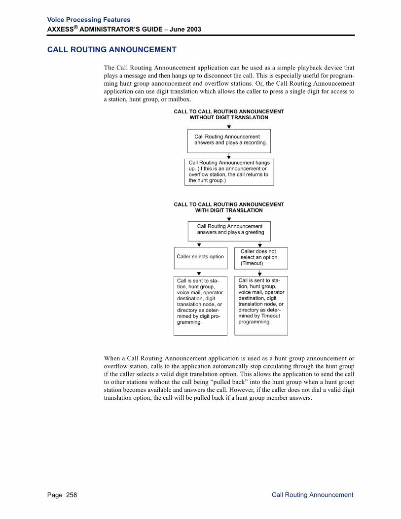
Voice Processing FeaturesAXXESS® ADMINISTRATOR’S GUIDE – June 2003
CALL ROUTING ANNOUNCEMENT
The Call Routing Announcement application can be used as a simple playback device thatplays a message and then hangs up to disconnect the call. This is especially useful for program-ming hunt group announcement and overflow stations. Or, the Call Routing Announcementapplication can use digit translation which allows the caller to press a single digit for access toa station, hunt group, or mailbox.
When a Call Routing Announcement application is used as a hunt group announcement oroverflow station, calls to the application automatically stop circulating through the hunt groupif the caller selects a valid digit translation option. This allows the application to send the callto other stations without the call being “pulled back” into the hunt group when a hunt groupstation becomes available and answers the call. However, if the caller does not dial a valid digittranslation option, the call will be pulled back if a hunt group member answers.
CALL TO CALL ROUTING ANNOUNCEMENT
Call Routing Announcement answers and plays a recording.
Call Routing Announcement hangs up. (If this is an announcement or overflow station, the call returns to the hunt group.)
WITHOUT DIGIT TRANSLATION
CALL TO CALL ROUTING ANNOUNCEMENT
Call Routing Announcement answers and plays a greeting
WITH DIGIT TRANSLATION
Caller selects option
Call is sent to sta-tion, hunt group, voice mail, operator destination, digit translation node, or directory as deter-mined by Timeout programming.
Call is sent to sta-tion, hunt group, voice mail, operator destination, digit translation node, or directory as deter-mined by digit pro-gramming.
Caller does not select an option (Timeout)
Page 258 Call Routing Announcement

Voice Processing FeaturesAXXESS® ADMINISTRATOR’S GUIDE – June 2003
CALL ROUTING CUSTOM AUDIOTEX RECORDINGS
When accessed, the Call Routing Announcement application will play a custom audiotexrecording and then hang up.
Call routing announcements are recorded using the voice mail administrator’s mailbox asdescribed on page 43. Each announcement is assigned to use a “custom greeting” number inDatabase Programming.
Recordings for fax documents should include all dialing instructions. The recording shouldstate whether documents can be selected by number and/or list all options. If fax delivery timesare set to specific days or times, the recording should also include this information.
CALL SCREENING
Calls transferred from the Automated Attendant or a Call Routing Announcement applicationcan be screened, announced, or unannounced. Separate programming flags determine themethods used for transferring calls to stations with mailboxes, stations with extension IDs, andextensions without mailboxes or IDs. (See page 189 for details.)
DIGIT TRANSLATION
Digit translation allows callers to dial a single digit to access a designated extension number,mailbox, or hunt group. Up to 12 digit translation storage locations (#, *, 0-9) are available foreach Call Routing Announcement application. To use digit translation, the Call RoutingAnnouncement application must have special programming.
After the application is created and programmed, the voice mail administrator’s mailbox isused to make a custom audiotex recording that explains the options to callers, as described onpage 43. The custom audiotex recording is then assigned to the Call Routing Announcementapplication. A caller who listens to the Call Routing Announcement recording can dial the sin-gle-digit location number to reach the designated destination. For example, if the hunt groupextension for a customer support group is programmed for digit 3, the recording should saysomething like, “For customer support, press 3.”
The system provides a choice between Primary and Secondary Language prompts and dis-plays. The available languages are American English, British English, Spanish, and Japanese.The system selects the language to use for each call, as determined by the trunk, station, andVoice Processor programming. When using a Call Routing Announcement application withdigit translation, the individual Voice Processor applications assigned to the digits can be pro-grammed to override the device language and provide prompts in one language only. Usingthis method, you can program a Call Routing Announcement tree that offers callers a choicebetween languages. See page 155 for more information.
DIGIT TRANSLATION NODES
A “digit translation node” is a digit translation destination that allows further digit translationoptions. Unlike extension and mailbox destinations, a digit translation node does not move thecall to a specific location. Instead, it offers additional dialing options. A digit translation nodecan use any of the Actions, including transfers to other digit translation nodes.
The use of digit translation nodes allows the programmer to create a Call Routing Announce-ment with several layers to form a digit translation “tree.” The tree can be made up of digitswith destinations and/or digit translation nodes with additional translations. An example of aCall Routing Announcement application with a multi-layered tree is shown on the next page.
Page 259Call Routing Custom Audiotex Recordings

Voice Processing FeaturesAXXESS® ADMINISTRATOR’S GUIDE – June 2003
FIGURE 11. Sample Call Routing Announcement Tree
EXT 2500: “Thank you for calling X Company, if you know the party’s extension number, you may dial it now. For a company directory, press #. For Sales information press 3. For technical support, press 4.”
Call is sent to extensionnumber dialed
Transfer to Hunt Group2001 (Tech Support)
CompanyDirectory
CALLER DIALS # CALLER DIALS 3CALLER DIALS ANUMBER THAT BEGINS
WITH 1
CALLER DIALS ANUMBER THAT BEGINS
WITH 2
Transfer to Sales Node: “To speak to the operator, press 0. To select Sales information by fax, press 1. To speak to a Sales repre-sentative, press 2.”
CALLER DIALS 1 CALLER DIALS 2C ALLER DIALS 0
Transfer to Extension2000 (Sales Hunt Group)
Transfer toOperator
Transfer to Node (Sales Info Fax): “If you know the fax document number, please dial it now. If you wish to speak to the oper-ator, dial 0. For a product list, dial 2. For a price list, dial 3. For training information, dial 4. Then press # to check your selec-tions and enter your fax number or press * to cancel.”
Transfer to Operator
Fax with that number is selected.
Selects Fax Document 1999 - Product List
Selects Fax Document 1998 - Price List
Selects Fax Document 1997 - Training
End Fax Selections: System requests dialing infor-mation and send fax, then returns to Main Menu.
Cancel Fax Selections: System returns to greeting.
CALLER DIALS 0
CALLER DIALS1997, 1998, or 1999
CALLER DIALS 2
CALLER DIALS 3
CALLER DIALS 4
CALLER DIALS #
CALLER DIALS *
CALLER DIALS 4
Page 260 Sample Call Routing Announcement Tree

Voice Processing FeaturesAXXESS® ADMINISTRATOR’S GUIDE – June 2003
FAX-ON-DEMAND
The Fax-On-Demand feature provides fax services to callers. It is a specially programmed CallRouting Announcement application that uses digit translation to allow callers to select the doc-uments they wish to have faxed to them.
With Fax-On-Demand, callers can use a DTMF telephone to request one or more documentsfrom the company’s fax library. (This library of fax documents is also used in the Unified Mes-saging faxing feature.) When the request is completed, the Voice Processor places a call to thecaller’s fax machine to deliver the requested documents.
The Fax-On-Demand process is shown in the following steps:
1. The caller reaches the Call Routing Announcement application either through directring-in or transfer.
2. After listening to the introductory recording, the caller selects a document by entering adocument number or using digit translation, depending on digit translation node pro-gramming. If the document is selected by number, the system will ask the caller to ver-ify the entry by pressing #. If the number is invalid, the system alerts the caller andreturns to the introductory recording.
3. The system checks the availability of the document, and one of the following occurs:
• If the document is available, the system tells the caller how many documents havebeen selected and how many more documents can be requested (as determined bythe Maximum Selections Allowed value in the database). It then returns to therecording to allow the caller to select more documents or end the selection process.
• If the document has been deleted or is being updated, the caller is told that the doc-ument is unavailable and returns to the recording.
4. If desired, the caller selects additional documents, and the system checks for their avail-ability as described above. If the maximum number of allowed documents has beenreached, the system informs the caller and gives the option of returning to the greetingor ending the selection process. If a caller selects the same document more than once,the system informs the caller of the error and allows another selection.
5. If desired, the caller can cancel the document selections at this point by pressing theCancel Fax Selections digit (usually *). However, once the next steps are completed,the faxes will be delivered.
6. When the caller ends the selection process by pressing the End Fax Selections digit(usually #), or reaches the allowed maximum number of documents, the systemrequests fax dialing information from the caller.
7. The caller enters and verifies his or her extension number (to be printed on the coversheet) and the caller’s fax machine telephone number.
8. The system checks the entered number, and one of the following occurs:
• If the number is valid, the system tells the caller when the document will be deliv-ered (this depends on the programmed fax delivery times in the Voice Processordatabase) and returns to the recording.
• If the number cannot be dialed by the Message Notification/Retrieval applicationdue to toll restrictions, the system tells the caller that the number cannot be dialedand asks for a new number.
• If the caller enters an invalid number, the system tells the caller the number isinvalid and asks for a new number.
Page 261Fax-On-Demand

Voice Processing FeaturesAXXESS® ADMINISTRATOR’S GUIDE – June 2003
9. The caller hangs up or returns to step 2 to select more documents. (If more documentsare selected and canceled, the documents that were selected and accepted previouslywill still be sent. Each time the caller accepts the documents and enters the dialinginformation, the documents are prepared for transmittal. They cannot be canceled afterthat point.)
10. The Message Notification/Retrieval application places a call to the caller’s fax machineas soon as a fax port is available, unless one of the following occurs:
• If the fax was requested outside of the programmed fax delivery times, the systemwill wait until the Fax Delivery Start Time on an allowed day of the week before itattempts to send the document. The Fax Delivery Start and Stop times determinewhen faxes can be sent. Start and stop times can be set to any time period, up to 24hours. The programmer can also determine which days of the week faxes will besent.
• If other calls are going out and the programmed Maximum Number of OutgoingCalls has been met, the system waits for an available outgoing call to send the fax.
• If a fax port or trunk is not available or if a requested document is not available,the system delays delivery until the resource or document is available.
• If a requested document has been deleted, the system will complete the delivery,but will indicate on the cover sheet that the document is no longer available.
• If a fax delivery fails after one or more pages have been transmitted, the systemremembers which pages were not sent and tries again to send only those pages. Forexample, if the transmission failed in the middle of page 3 of 5, the system wouldattempt to send only pages 3, 4, and 5 on the retry. The cover sheet on the retry willsay, “This fax is the continuation of...” and the description for the fax will include“continued” in the title.
Documents are stored in the fax library using the system administrator’s mailbox. To do so, afax machine places a call to the system administrator’s mailbox and sends the document. (Seepage 42 for instructions.)
Fax-On-Demand transmits a cover sheet with each faxed document that includes the recipient’sextension number, your company name (as programmed in the database), the date, the numberof pages to be sent, and a list of included documents. If you wish, you can store a companylogo to be used on the cover sheet. The logo can be up to 5.5 inches tall; if it is larger, the sys-tem automatically cuts it off at the 5.5 inch mark. The logo document is stored, like other faxdocuments, using the system administrator’s mailbox.
If you have several fax documents, you may want to create and store a “catalog” document thatcallers can request before continuing their selections. For example, the catalog can include thedocument number, title, description of the contents, number of pages, and last revision date foreach document.
Fax documents can be saved and restored using the Voice Processing Save And Restore data-base program. The system Save And Restore operation has no effect on fax documents. How-ever, if the system database is defaulted, all fax documents are deleted.
The digit translation node used for fax document selection should have a greeting that explainshow to select documents. For example, it can say something like, “Welcome to Fax-On-Demand. For a product list, press 1. For a price list, press 2. When you have made your selec-tions, press # to continue. Or, to cancel your selections, press *.” Or, you can use a series ofdigit translation nodes that break the document selection into categories and/or allow callers todial individual document numbers. If fax delivery times are set to specific days or times, theintroductory recording should also include this information.
Page 262 Fax-On-Demand

Voice Processing FeaturesAXXESS® ADMINISTRATOR’S GUIDE – June 2003
DIRECTORIES
There are two types of Voice Processor directories that can be enabled (or disabled) in the sys-tem: Mailbox and Extension.
• The Voice Mailbox Directory is a list of mailbox subscribers, their recorded names,and mailbox numbers.
• The Automated Attendant Directory, provided to all Auto Attendant callers, is a listof all mailbox subscribers and extension ID owners and their recorded names.
The directories can be selected in the following ways:
• From the voice mail or Automated Attendant main menu: Press the button.
• Using a Call Routing Announcement application: Press the Digit Translation digitdesignated for directory access. (See page 258 for a detailed explanation of digit trans-lation.)
• As a voice mail subscriber: Subscribers can access the directory by pressing when-ever they are prompted to enter a mailbox number.
If a directory is disabled or empty because no names are recorded for any of the system’s mail-boxes and extension IDs, callers will not hear the prompt that allows access to the directory.However, if the caller does press or a Directory menu button, the user will be instructedthat the selection is invalid and returned to the initial instructions.
Recorded names are added to the directories when the owner of the mailbox or extension IDhas initialized the name. If the mailbox or ID is not initialized, the directory will include onlythe mailbox number or extension ID number. (Group Lists are not included in either type ofdirectory.)
The caller uses the dialpad buttons to enter the name. The application then plays the closestmatching directory name that corresponds to the digits entered by a caller. Once the name hasbeen played, the system will return a menu of options, including the following:
• Listening to the previous or next name in the directory
• Listening to additional information (This option is not available if the mailbox or exten-sion ID number has been classified in the database as a “Private” number.)
• Spelling a new name
• Toggling from a last to first name search mode
• Accepting the name
#
#
#
Page 263Directories

Voice Processing FeaturesAXXESS® ADMINISTRATOR’S GUIDE – June 2003
LOCATING A NAME
Entering a Name
There are two methods used for entering a name: Quick Spell and Exact Spell. Outside callersand station users with non-display phones and single-line sets use Quick Spell. Display phonestations use the Exact Spell method.
• Quick Spell callers press a single digit (or button) from their digital telephone dial padfor each letter or character entered. For example, dialpad button shows ABC, button
shows DEF, etc. To enter JONES, you would press . Some char-acters are not shown on the buttons: for “Q” press , for “Z” press , for punctuationmarks press the button.
• Exact Spell callers press the dialpad buttons to enter the name. The number of times abutton is pressed determines which character is entered, as shown on the chart below.When adjoining characters are located under the same button, press once toadvance to the next character. For example, 5666 66337777 would enter“JONES.”
After the digits have been entered, the caller presses to begin the search. The AutomatedAttendant application plays the name that most closely matches the digit(s) that were entered.If is pressed without entering any digits, the caller will hear the first name in the directory.
If a user presses at any time while spelling a name, the system will play a helpful promptinstructing the caller how to enter a name. (Display phone users will receive Exact Spellinstructions; all other users will hear Quick Spell instructions.)
Changing the First/Last Name Search
Each directory can be programmed to be organized by last name or by first name. Callersaccessing a directory receive system voice prompts that ask them to enter the first or last nameof the person for whom they wish to leave a message.
If an Executive Display, Professional Display, or Model 8560 Phone with menu buttons is usedto access a directory, the caller may switch back and forth from looking up a last name, to afirst name simply by pressing the corresponding menu button. Callers using other Inter-Telphones or single-line sets can press to toggle between last and first name.
NUMBER OF TIMES BUTTON IS PRESSEDBUTTON 1 2 3 4 5
1 - & ( ) 12 A B C ’ 23 D E F ! 34 G H I * 45 J K L # 56 M N O Ñ 67 P Q R S 78 T U V ? 89 W X Y Z 90 @ : . , 0
2
3 5 6 6 3 7
7 9
1
FWD
FWD
#
#
0
5
Page 264 Locating a Name

Voice Processing FeaturesAXXESS® ADMINISTRATOR’S GUIDE – June 2003
Listening to the Next/Previous Name
After a name has been played, the caller can listen to the previous name in the directory bypressing . To listen to the next name, the caller can press .
The directory lists are circular. That is, when the end of the list is reached, the next nameplayed will be the first name in the directory. Or, if the caller scrolls to the beginning of the list,the “previous” name played will be the last name in the directory.
ACCEPTING A NAME
When the caller is using the voice mail feature and accepts a name, the caller is transferred tothe corresponding mailbox. Then the caller will hear either the subscriber’s recorded greeting,recorded directory name, or, if no recording has been made, the “mailbox number XXX is notavailable” prompt. The caller can then record a message.
If the caller is using the Automated Attendant feature, and accepts the name, the caller is trans-ferred to the selected destination (station or mailbox) if it is available. If a station extension isdialed and the destination is not available, the caller is sent to the associated mailbox, if oneexists.
REQUESTING ADDITIONAL INFORMATION
After a name is selected from the directory, the caller has the option of requesting additionalinformation. When requested, the mailbox number, extension number, and name are played (ifthey have not been disallowed).
Individual mailboxes and extension IDs can be programmed as “Private” in Database Program-ming. A Private number is included in the directory and can be dialed by a caller who knowsthe number, but the associated mailbox and extension number information are not available tothe caller; only the name is played.
Mailboxes and extension IDs can also be programmed as “Unlisted.” That means that the num-ber will not be included in the directory, but can be dialed if the caller knows the extensionnumber.
USING THE DIRECTORIES
TO USE A DIRECTORY:
1. Dial the voice mail access number. You hear the recorded system greeting.
2. Press to access the Directory Services application.
3. The buttons on your telephone are labeled with letters. Use Quick Spell (non-displayphone or single-line) or Exact Spell (display phone) to enter the desired name, asdescribed on page 264, then press . (If you wish to exit from the directory withoutselecting a name, press or hang up.)
4. The voice mail application will play the selected name. Do one of the following:
• To accept the name: Press .
• To hear the previous name in the directory: Press .
• To hear additional information for the selected name (if allowed): Press .
• To hear the next name in the directory: Press .
• To spell a different name: Press and repeat step 3.
• To switch the first/last name sort order: Press .
1 3
#
#
#
1
2
3
4
5
Page 265Accepting a Name

Voice Processing FeaturesAXXESS® ADMINISTRATOR’S GUIDE – June 2003
RECORD-A-CALL
NOTE: The Record-A-Call premium feature is required to use Record-A-Call.
If the Voice Processor has a Record-A-Call application, the users can enter a feature code torecord ongoing calls in their designated Record-A-Call mailboxes. Users can retrieve therecorded messages later, just as they would any other mailbox message.
The Record-A-Call mailbox records the call as a voice mail message. All parties will beincluded in the recording. If desired, the Record-A-Call mailbox can be programmed to play amessage announcing that the Record-A-Call feature is in progress. There can be separate mes-sages for day and night modes.
A Record-A-Call tone can be programmed to alert callers at the beginning of the recording.Also, it can be programmed to beep periodically throughout the recording.
There are two ways a station can be programmed to use this feature:
• The station can use its personal mailbox, or any other mailbox, as the assigned Record-A-Call mailbox. No other mailbox can be selected. (This is the default programming forall stations.)
• The station can be programmed with a default mailbox, but with the option of selectinga different mailbox. If the user chooses to not enter a mailbox number, the system auto-matically selects the default mailbox.
When the requesting station user hangs up, all parties are automatically disconnected. If allparties on the call hang up, except the requesting station user, an intercom call will remain con-nected between the requesting station and the Record-A-Call application. This allows the userto make additional comments before ending the recording.
When the station user turns off Record-A-Call or ends the call being recorded, the Voice Pro-cessor delivers the message to the mailbox. The station associated with the mailbox willreceive message waiting indications as usual. See page 278 for message retrieval instructions.
The programmer can set a maximum length for Record-A-Call messages. The Record-A-CallMaximum Message Length timer can be set at 0-600 minutes. A 0 setting allows messages ofany length, limited only be the available disk space. The default is 30 minutes.
In a network setting, the Record-A-Call destination does not have to be on the same node asthe station, but the Voice Processor must have a mailbox for that station.
For more information on using the Record-A-Call feature, refer to page 196.
Page 266 Record-A-Call

Voice Processing FeaturesAXXESS® ADMINISTRATOR’S GUIDE – June 2003
SCHEDULED TIME-BASED APPLICATION ROUTING (STAR)
Scheduled Time-Based Application Routing (STAR) allows you to have applications withalternate greetings and/or different programming set up for holidays, weekends, and otherscheduled events.A STAR application is basically a “routing table” for Voice Processor applications. When adirect ring-in call (from a trunk group or call routing table) rings in to a STAR application, itsends the call to another application, according to its programmed schedule. The caller will notbe aware of this transfer, but will hear the programmed day or night greeting for the destinationapplication. (The STAR application itself does not play a greeting.)STAR can be used with any type of application except Auto Attendant Recall and Record-A-Call. You can even send calls from one STAR application to another, thereby “chaining” theapplications to increase the number of available schedules.A STAR application can contain up to 20 scheduling entries with the following fields:
• Application: This is the application (call routing announcement, automated attendant,etc.) that will be used when the scheduling information applies to the incoming call.
• Start/Stop Date: If the schedule is going to be active on a single day or for a period ofdays, it will have Start and Stop Dates. (To have the schedule active on only one day,the Start and Stop Dates can be the same day.)
• Days of the Week: The schedule can be used on specific days of the week.
• Specific Times or Day/Night Mode: The schedule can be set to be active for a specificperiod of time on the selected day(s). Or, it can be set to be active in day or night mode.
The chart below shows several samples of STAR entries. Note that there are two entries forLabor Day and Memorial Day, and that Christmas Day and Christmas Holiday overlap. Thefirst entry in the table is checked first, and so on, until a match is found. So it is important thatyou program the applications in the correct order. For example:
• The Labor Day entry, with a specific time, comes before the Day/Night entry so that adifferent message is played from 10:00 to 2:00 only.
• The early time intervals come before the later intervals on Memorial Day.
• Dec 25 comes before the range of dates Dec 24- Jan 4 so that the special holiday mes-sage will be played on that day only.
Once a match is found, the application corresponding to the matched entry is invoked. If nomatch is found, the application programmed in the “Default Application” field is used.When programming the days and times, be careful not to overlap. For example, if you place adate entry for Dec. 25 after a day of the week entry for Monday, and Christmas falls on a Mon-day, the “Monday” application will be selected instead of the “Dec. 25” application.
ENTRY DESCRIPTION DATE DAY TIME INTERVAL DAY/NIGHT APPLICATION
1 Labor Day Sep 1 10:00am-2:00pm 26002 Labor Day Sep 1 Both 26013 Memorial Day May 30 8:00am-5:00pm 26054 Memorial Day May 30 5:00pm-8:00am 26065 Christmas Day Dec 25 Both 26076 Christmas Holiday Dec 24 - Jan 2 Both 26087 Weekends Sat, Sun Both 26128 Lunch Break M - F 11:00am- 1:00pm 26139 Night Shift M - F Night 261410 Day Shift M - F Day 2615
Page 267Scheduled Time-Based Application Routing (STAR)

Voice Processing FeaturesAXXESS® ADMINISTRATOR’S GUIDE – June 2003
SMDR INFORMATION STORAGE AND RETRIEVAL
The Voice Processor PC can be used to capture Station Message Detail Recording (SMDR)information. The SMDR information is stored in a file on the Voice Processor PC’s hard diskfor later retrieval.
Every time a call is completed, the SMDR feature records the call, formats it according toSMDR programming (see page 244), and sends the record to the SMDR output device, ifenabled. The formatted record is also sent to the Voice Processor if SMDR buffering isenabled.
The Voice Processor PC adds each call record to the SMDR buffer file as it is received. Theamount of disk space allocated for SMDR storage is determined in Database Programming.The default value is zero megabytes of memory. If the call records use disk space exceeding80% of the allotment, the system generates an alarm and displays it at the primary attendantstation and all telephone system administrator stations. Another alarm message is generated ifthe allotted space is 100% filled. If the maximum buffer capacity is exceeded, the oldest callrecord(s) are discarded as new ones arrive.
NOTE: Since each SMDR call record takes up approximately 81 bytes on the Voice ProcessorPC, nearly 13,000 calls can be stored in each megabyte of hard disk space.
The SMDR records, which are stored in ASCII/binary format, are buffered until they arecleared by the programmer. If desired, the programmer may save and/or restore SMDR data(along with the system database) to floppy disks using the Voice Processing Save and Restorefeature.
If desired, the SMDR records can be retrieved and processed using Inter-Tel’s Inside Track®, aseparate call accounting software package, to create customized reports.
In a network setting, the Voice Processor will buffer SMDR records that are sent from othernodes in the network.
Page 268 SMDR Information Storage and Retrieval

Voice Processing FeaturesAXXESS® ADMINISTRATOR’S GUIDE – June 2003
VOICE MAIL
The voice mail feature allows callers to send and receive recorded messages from any stationor DTMF telephone. (Dial-pulse signaling is not recognized by the Voice Processor. Callersusing dial-pulse phones will be routed to the voice mail application’s Dial-0 Destination forassistance.)
VOICE MAIL AND MESSAGE NOTIFICATION/RETRIEVAL APPLICATIONSTwo types of applications are combined to provide the voice mail feature: Voice Mail and Mes-sage Notification/Retrieval.
• Voice Mail: This applicationhandles all calls that are directedto voice mail (other than theMessage Notification/Retrievalapplication) placed by subscrib-ers and non-subscribers. Callerswill hear the main companygreeting, followed by a menu ofavailable options. Stations canforward or transfer calls directlyto their mailbox using this appli-cation’s extension number. Thisapplication can also be the mes-sage center for the subscribers’stations.
• Message Notification/Retrie-val: Only one Message Notifi-cation/Retrieval application maybe created for the system. Whenstation users respond to messageindications left by voice mail,they reach the Message notifica-tion/Retrieval application andare prompted only for theirpassword.
CALL TO VOICE MAIL
Voice mail answers and plays a greeting followed by a menu of options.
Caller selects option Caller does not select an option
Call is sent to selected mailbox.
Caller uses the directory and can select the name of desired party.
Call is sent to mailbox. Or a subscriber enters his own mailbox.
Call is sent to the voice mail designated dial-0 operator.
MESSAGE IS LEFT IN A MAILBOX
Voice mail leaves a message waiting indica-tion at the station designated as the message notification station for the mailbox.
Station user is prompted for the password to his mailbox.
Station user responds to message indication (presses MSG button or enters feature code).
INTERCOM CALL IS PLACED TOMESSAGE NOTIFICATION/RETRIEVAL
APPLICATION (Alternate Message Source)
Page 269Voice Mail

Voice Processing FeaturesAXXESS® ADMINISTRATOR’S GUIDE – June 2003
Station users and outside callers gain access to the voice mail application in the followingways:
• By dialing the telephone number or extension number assigned to the voice mail appli-cation
• By being transferred to the voice mail by the automated attendant
• By being forwarded to the voice mail when a called station is unavailable (via the CallForwarding or System Forwarding features)
• By responding to message waiting indications
Callers will hear the voice mail company greeting and recorded instructions that tell them whatto do next. Users simply listen to the prompts and press the dialpad button that corresponds tothe desired choice. If the user does not respond immediately, a second set of prompts is played.
Most prompts are interruptible, and users can press the desired button at any time during theprompt. The prompt will then stop and the system will act on the requested choice.
Page 270 Voice Mail and Message Notification/Retrieval Applications

Voice Processing FeaturesAXXESS® ADMINISTRATOR’S GUIDE – June 2003
MAILBOXESA mailbox is a storage location on the Voice Processor PC hard disk that stores all messagesthat have been directed to it. (The hard disk also stores prompts, greetings, and special pro-gramming.) Each “Subscriber” (member of the voice message system) is assigned a uniquemailbox number. At system default, the passwords are the same as the mailbox numbers. (Forexample, the default password for mailbox 1001 is “1001.”)
There are three types of mailboxes on the voice mail system: Standard, Receive-Only and Sys-tem Administrator. There can also be Extension IDs which are stations that do not have mail-boxes, but that are included in the recorded directory.
• The Standard mailbox owner receives all of the available subscriber options as autho-rized through database programming. Standard mailbox features include:
— Listening to new messages— Recording and sending messages
— Deleting and restoring messages
— Saving messages
— Personal options (greeting, password, etc.)
— Remote messaging (if authorized through database programming)
• A Receive-Only mailbox type may only listen to new messages, save, delete, or recoverthem and access personal options. This type of mailbox is restricted from recording andsending messages and has no access to remote messaging.
• There can be only one voice mail administrator. The voice mail administrator has all ofthe options a Standard mailbox subscriber has, plus these features:
— Record and send broadcast messages to all subscribers of the voice mail system
— Provide mailbox and group list maintenance
— Record and select Custom Audiotex Recordings
• Extension IDs are used in conjunction with transferring calls through the AutomatedAttendant or using the Extension Directory. The extension ID allows callers to be trans-ferred to station extensions which do not have mailboxes and allows the station user torecord a directory name and set up a password.
Calls transferred from the Automated Attendant or a Call Routing Announcement applicationto a station with a mailbox can be screened, announced, or unannounced. Separate program-ming flags determine the methods used for transferring calls to stations with mailboxes.
Page 271Mailboxes

Voice Processing FeaturesAXXESS® ADMINISTRATOR’S GUIDE – June 2003
During database programming, each mailbox is assigned a dial-0 operator destination. When acaller presses while listening to the mailbox’s personal greeting or recording instructions,or while recording a non-subscriber message, the operator destination is called. The operatorcan be one of the following types:
• Mailbox: If the operator is a mailbox, the caller will hear the operator destination’s per-sonal greeting after pressing .
• Station extension number: If the operator destination is an extension number, thecaller will hear the Automated Attendant transfer prompt while the call is placed to theextension number (“Please hold while I transfer your call to...”), unless it has been dis-abled at the mailbox. If the station user does not answer, the caller will be asked if hewants to leave a message, if the operator’s extension has an associated mailbox. If thecaller chooses not to leave a message, the call returns to the main menu of the applica-tion being used (Call Routing Announcement, voice mail, or Auto Attendant).
• Application extension number: If the operator destination is an application’s exten-sion number, the call is transferred to that application’s main menu.
• Operator: If the operator destination is set to “Operator,” the caller will be transferredto the operator destination programmed in the Voice Processor database.
• None: If the operator destination is set to “None,” the will be ignored.
GROUP LISTSGroup lists are programmed in the database. They are lists of mailboxes that can be used byany Subscriber for sending messages to several mailboxes simultaneously. The informationthat is programmed for group lists include the following:
• Group list description
• Group list number• Mailboxes included in the list
There can be up to 1000 group lists in the system and up to 1500 entries per group list.
Group Lists are not included in the Automated Attendant or voice mail directories.
Instructions for using group lists are given on page 281.
0
0
0
Page 272 Group Lists

Voice Processing FeaturesAXXESS® ADMINISTRATOR’S GUIDE – June 2003
MESSAGE NOTIFICATION TO STATIONS
Each mailbox has a programmed Message Notification Station. This is usually the extensionnumber that matches the mailbox number (associated mailbox). However, a different numbercan be used for the mailbox’s message notification station (non-associated mailbox).
• Associated: When the extension number, message notification number, and mailboxnumber for a station all match, that station user can forward calls to voice mail and havethe call go directly to the associated mailbox’s personal greeting. (Even if other mail-boxes use that extension number as their message notification extension.)
• Non-Associated: The extension number assigned as the Message Notification Stationfor a non-associated station is an extension number that does not match the mailboxnumber. (For example, a hunt group pilot number can have a mailbox, but the messagenotification must be sent to a specific station so that a message lamp can be lit or mes-sage notification signal can be sent.) If a station user’s extension number does notmatch a mailbox number, and the station user forwards calls to voice mail, the callerwill hear the main voice mail greeting and must enter a mailbox number.
When a mailbox receives a message, the message notification station is signaled. If it is anInter-Tel phone, the button is lit and the display shows that a message has beenreceived. A single-line set will receive message waiting signals, if enabled system-wide.
CASCADING REMOTE MESSAGE NOTIFICATION
Remote Messaging is a subscriber feature that is enabled through database programming. Sub-scribers may program a series of specific telephone numbers (a “cascade”) for the voice mailsystem to call when new messages are received by their mailboxes. Refer to page 283 for sub-scriber instructions on using Personal Options to set up remote messaging.
Primary and Alternate Notification
Each mailbox can have a Primary and/or an Alternate notification cascade of numbers. Thenotification numbers are programmed to be accessed during specific days and times.
The voice mail system monitors subscriber mailboxes continuously. During monitoring, if newmessages have been received, the system will check to see if Primary notification is turned on.If it is, the system will check the day and time programming. If the current time is within theprogrammed notification day and time, the voice mail system will make the notification call(s)to the numbers in the Primary Notification cascade. If Primary Notification is turned off or ifthe day or time does not match, the voice mail system will immediately make the same checkfor Alternate Notification and possibly place calls to the numbers in the Alternate Notificationcascade.
When the Voice Processor makes a notification call, it moves through the appropriate notifica-tion cascade level by level as determined by the notification and retry programming describedbelow. When the system reaches the last level in the cascade, it will return to level 1 and beginagain, if necessary.
If the system is not able to place the call within the parameters of the programmed notificationday and time (due to busy facilities or invalid programming), the mailbox will receive a mes-sage stating that notification could not be completed (the mailbox owner will hear the messagenext time he or she accesses the mailbox.)
The number of calls that the Voice Processor can process simultaneously is determined by theMaximum Number of Outgoing Calls flag. It defaults to 2, but can be programmed to use all ofthe enabled Voice Processor voice channels.
MSG
Page 273Message Notification to Stations

Voice Processing FeaturesAXXESS® ADMINISTRATOR’S GUIDE – June 2003
All Messages, Priority Only, and Each New Message Flags
When the mailbox is being programmed for remote notification, message notification can beset to place the notification call when any message is received or only when priority messagesare received. (This defaults to “All Messages.”) Another mailbox flag, called “Call For EachNew Message,” determines when the Voice Processor will attempt to make the notification callwhen more than one message is waiting to be heard:
• If the Call For Each New Message flag is enabled, the Voice Processor will attemptimmediate notification each time a new message (or priority message, depending on theoption selected) is received, regardless of the status of the applicable retry timer. If aretry is in progress, it will place the call to the number on the cascade table that wouldhave received the retry call, as described below. (For example, if the Voice Processorwas on level 3 of a cascade, attempting retries, it will not start over again at level 1. Itwill place the call to level 3.)
• If the Call For Each New Message flag is disabled, new messages will not generate aremote notification attempt until the Subscriber has logged on and listened to the wait-ing message(s). (However, retry calls will be attempted if the applicable retry timerexpires, as described below.)
Retry Call Attempts
The mailbox can be programmed to retry notification calls when it encounters a busy trunk ortrunk group. Each cascade level can be programmed with a Number of Call Attempts value of1-1000 calls.
If the mailbox user accesses the mailbox between the time the message is received and whenremote notification is successful, the system will stop attempting remote notification. It isassumed that the mailbox user listened to the message when the mailbox was accessed. How-ever, the button at the station will remain lit if there are any messages that have notbeen heard.
Each level also has a Number Called Busy timer and a Pager Notification Retry timer or Per-sonal Number No Answer timer. These timers determine how long the Voice Processor willwait before making the next notification attempt when messages are waiting to be heard(unless it is overridden by the Each New Message flag). These timers can be set to a value of0-255 minutes. If set to 0, it retries the cascade level immediately, for as many attempts asallowed by the Number of Call Attempts field. If the message(s) has not been picked up bythen, the system moves to the next cascade level. The default setting for the Pager NotificationRetry timer is 20 minutes. The Number Called Busy and Personal Number No Answer timersdefault to 5 minutes.
NOTE: The 0-minute timer value should be used cautiously. If the system is forced to makeseveral calls in quick succession, it will impair the Voice Processor's ability to place other outgo-ing calls. It should be used primarily with cascades in which all of the members wish to receivenotification at approximately the same time. In this case, all levels except the last could be set to0-minute retries with 1 allowed call attempt. However, the last level in the cascade should beprogrammed with a longer Pager Notification Retry timer so that the system does not continu-ously cycle through the cascade levels. (Continuous cycling is also prevented somewhat by aper-mailbox 15-call limit. Due to FCC regulations, the Voice Processor can allow a mailbox tomake only 15 calls in rapid succession without a 10 minute pause.)
MSG
Page 274 Cascading Remote Message Notification
Voice Processing FeaturesAXXESS® ADMINISTRATOR’S GUIDE – June 2003
Notification Numbers
Each cascade level has a programmed notification number that can be an extension number oran outside telephone number.
When an outside telephone number is used, the system will access an outgoing trunk using thecode programmed for that level that contains a pre-programmed trunk access code and fol-lowed by an outgoing access termination feature code, if needed.
Notification calls to outside telephone numbers can be sent to a pager or to a number where aperson will answer (personal number).
• If the call goes to a pager, the system will dial the programmed Pager Dial String, thendisconnect the call. The dial string should include any digits that the paging companyrequires when the call is answered, the pager LCD number, and the pager terminationcode, if needed. Also, if desired, the pager string can be programmed to show the num-ber of the mailbox that placed the call and/or the number of waiting messages in themailbox.
• If the call goes to a personal number, the system will play a prompt announcing that thecall is from voice mail, play the directory name or mailbox number that originated thecall, and play user instructions. The listener can then enter the mailbox number’s pass-word to gain access to the mailbox and hear the message. The listener has three chancesto enter a correct password. If the system receives an incorrect password three times,the voice mail system will disconnect the call immediately, and the attempt is consid-ered unsuccessful.
Page 275Cascading Remote Message Notification

Voice Processing FeaturesAXXESS® ADMINISTRATOR’S GUIDE – June 2003
USING VOICE MAIL
Voice mail subscriber features include the following:
• Listen to new messages, if any
• Send a message
• Listen to saved messages, if any
• Set personal options
• Set up remote messaging, if enabled
When a subscriber enters the mailbox, the voice mail application may play one of the follow-ing messages:
• Mailbox almost full or full: If a mailbox is full, no new messages can be received atthat mailbox until the subscriber deletes waiting or saved messages.
• Message count: A prompt tells the subscriber how many messages are waiting to beheard, if any, and how many are priority messages.
• Remote messaging: A prompt will indicate whether primary or alternate remote mes-saging is selected when remote messaging is enabled. It will also alert the subscriber ifa programming error has been detected and/or whether the system encountered busyresources when attempting to place a remote messaging call.
ACCESS TO A MAILBOXA SUBSCRIBER CAN ACCESS HIS OR HER MAILBOX BY FOLLOWING THESE STEPS:
1. Dial the voice mail application access number. You hear the main menu.
2. During or after the greeting, press to identify yourself as a subscriber.
3. Enter your mailbox number and personal password.
Page 276 Using Voice Mail

Voice Processing FeaturesAXXESS® ADMINISTRATOR’S GUIDE – June 2003
INITIALIZING A SUBSCRIBER MAILBOX OR EXTENSION IDThe first time a subscriber uses voice mail, he or she must customize the mailbox. Systemprompts will instruct the subscriber to:
• Change the default password number (same as the mailbox number) to a personal pass-word.
NOTE: To provide system security, all mailboxes should have a password. To makethe passwords difficult to guess, they should not match the mailbox number or consistof one digit repeated several times. The default password should be changed the firsttime the user logs in. This is especially important in the system administrator's mailboxwhich, allows programming access to the Voice Processor.
• Record a name to identify the mailbox owner in the company directory. (Directorynames can be up to 1 minute in length.)
• Listen to the voice mail application introduction. (You can skip this introduction bypressing , if desired.)
TO INITIALIZE A MAILBOX OR EXTENSION ID:
1. Dial the voice mail extension number. (You hear the main menu.)
2. Press to identify yourself as a subscriber.
3. Enter your mailbox number and default password. (Your default password is your mail-box number.)
4. If you want a password, enter a new password using digits 0-9 (up to 12 digits). Thenpress . Voice mail plays back your password.
5. If you do not want to use a password, just press .
6. Press to accept the entry. (Or, press if you wish to re-enter your password.) Thesystem prompts you to record your directory name.
7. After the tone, record your first and last name. When finished, press .
8. Press again to accept the name. (Or, press to replay the name you just recorded,press to add to your name, or press to erase and re-record it.)
9. The system then plays a prompt that introduces you to the basic voice mail features.(You can skip this introduction by pressing , if desired.)
Once your mailbox is initialized, you may use any of the mailbox features provided. To recorda personal greeting, or to change your password or directory name, refer to page 283.
#
#
#
# 3
#
# 12 3
#
Page 277Initializing a Subscriber Mailbox or Extension ID

Voice Processing FeaturesAXXESS® ADMINISTRATOR’S GUIDE – June 2003
LISTENING TO MESSAGESThere are three types of voice mail messages:
• New Messages are messages that you have not yet heard, including Broadcast Mes-sages from the voice mail administrator and system-sent messages. The order in whichthe messages are played depends on your message retrieval setting (see page 283),except that messages marked “priority” are played first. Some special messages thatmay be played include the following:
— Message receipt: If you send a certified message, a system message will be playedwhen the recipient has listened to the message.
— Caller Information: If a call was placed to your mailbox on a trunk that supportsthe Caller ID feature, and the caller hung up without leaving a message, a systemmessage will be played informing you that the calling party did not leave a mes-sage. It will also include, within the corresponding message envelope, the numberof the calling party as the message source.
— Security violation: The voice mail system has an extra security measure built inwhich plays a message, when you log into your mailbox, that tells you if threeinvalid attempts have been made to access your mailbox within a single call. Thisannouncement message will be sent to your mailbox each time this situationoccurs. It is received as a new message and is accompanied by a message envelope.
• Saved Messages are messages that you previously listened to and saved (or deleted andrestored). You can play them back, as necessary, based on your message retrieval set-ting.
• Undeliverable Messages are messages you have left for a mailbox on another node,that cannot be delivered. They are returned to you as “undeliverable.”
The Return Call feature allows voice mail users to return a call to the person who left a mes-sage, as long as the call was received from an extension number or an outside number withCaller ID. It is part of the “Reply” option described in the following procedure.
Page 278 Listening to Messages

Voice Processing FeaturesAXXESS® ADMINISTRATOR’S GUIDE – June 2003
Whenever you access voice mail as a subscriber, you are told how many new and saved mes-sages you have.
FROM THE MAIN MENU:
1. EITHER, Press to listen to your new messages.
OR, Press to listen to your saved messages.
2. The system plays each message in the queue selected. While you are listening to a mes-sage, you can use the following options:
• Press to skip to the end of the envelope or recording.
• Press to back up.
• Press to pause. (Then press any button to continue.)
• Press to skip ahead.
• Press to lower the volume.
• Press to play the message envelope again.
• Press to raise the volume.
• Press to save the new message in your mailbox.
• Press to delete the message from your mailbox.
3. When the message has finished playing, you have the following options:
• Press to replay the message from the beginning.
• Press to reply to the message. You can then do one of the following:
— Press to leave a voice mail message for the caller. If the caller had a mail-box number, it will ask you to verify the destination by pressing . If thenumber was not associated with a mailbox, it will ask you to enter a mailboxnumber. If the message was from an outside caller, you cannot leave a voicemail message.
— Press to make a return call. Your call will be transferred automatically tothe caller’s extension or telephone number, if available. If the extension num-ber is not available, you will have the option of leaving voice mail. If the tele-phone number is not available, you cannot reply to the message.
• Press to forward a copy of the message to another subscriber. If you want toinclude introductory comments, press and record an introduction. If not, press
to forward the message without an introduction.
• Press to listen to the previous message.
• Press to play the introductory message “envelope” again.
• Press to listen to the next message.
• Press to save the new message in your mailbox.
• Press to delete the message from your mailbox.
1
3
#
1
2
3
4
5
6
7
9
1
2
1
#
2
31
#
4
5
6
7
9
Page 279Listening to Messages

Voice Processing FeaturesAXXESS® ADMINISTRATOR’S GUIDE – June 2003
RECOVERING DELETED MESSAGESThis feature allows you to “undo” the Delete Message operation and restore previously deletedmessages. The messages will be restored to your saved-message queue. You have a set amountof time to recover messages, depending on database programming (up to 24 hours). After that,voice mail will erase them.
TO RECOVER DELETED MESSAGES:
1. Dial the voice mail application access number. You hear the main menu. 2. During or after the greeting, press to identify yourself as a subscriber. 3. Enter your mailbox number and password. 4. When you hear the Main Menu list of options, press to select Message Options.
Some Inter-Tel phone users will also see Message Options on their display menu. 5. The next prompt gives you the option of recovering deleted messages. Press to con-
tinue.
6. Your options are:
• Press to listen to your deleted messages and choose which ones to delete orrecover. After each message you can:
— Press to replay the message.
— Press to reply to the message.
— Press to forward the message to another mailbox.
— Press to listen to the previous message.
— Press to replay the message envelope.
— Press to listen to the next message.
— Press to recover the message.
— Press to purge the message from your mailbox.
• Press to recover all of your deleted messages and store them as saved messages.
• Press to purge all of your deleted messages so that they are erased from voicemail.
5
2
1
1
2
3
4
5
6
7
9
2
3
Page 280 Recovering Deleted Messages

Voice Processing FeaturesAXXESS® ADMINISTRATOR’S GUIDE – June 2003
SENDING A MESSAGE
As a subscriber, you can record and send voice messages to other users from the subscriberMain Menu.
FOLLOW THESE STEPS:
1. Dial the voice mail application access number. (You hear the main menu.)
2. During or after the greeting, press to identify yourself as a subscriber.
3. Enter your mailbox number and personal password.
4. When you hear the Subscriber Menu, press to send a message.
5. Dial the desired mailbox number or group list number. If you do not know the mailboxnumber, you can press to access the company directory to locate and select the mail-box. See page 268 for directory instructions. Group lists are not included in the direc-tory.
If the mailbox is full, a prompt will notify you that the mailbox cannot receive mes-sages. However, it will allow you to leave a message at another mailbox. Leave yourmessage with another subscriber or try again later.
6. After hearing the subscriber’s name, press to accept it.
7. The subscriber’s mailbox message is played (To skip this message, press .) Whenyou hear the tone, record your message. When finished, hang up or press and go tothe next step.
NOTE: If the system detects silence for longer than 5 seconds, it will prompt you tospeak up. The recording, if any, will remain unchanged.
• To pause while recording: Press . To continue, press any button. (The pauselength is determined by the Pause Voice Mail timer.)
• To erase your message: Press .
If you exceed the maximum allotted time for message length, a prompt will notify youand allow you to re-record the message or send the message as it is.
If voice mail is full, a message will notify you that it cannot accept your message. Hangup and try again later.
8. When you have completed your message, you have the following options:
• To hear your message: Press .
• To add to your message: Press and continue your message.
• To erase and re-record your message: Press .
• To use the special delivery option: Press . Go to the next step.
• To send your message: Press . (If you wish to mark the message certified, pri-vate, and/or priority, do so before completing this step.) If you wish to send anothermessage, return to step 5.
2
#
#
##
2
3
1
2
3
9
#
Page 281Sending a Message

Voice Processing FeaturesAXXESS® ADMINISTRATOR’S GUIDE – June 2003
9. You can do one or more of the following if you selected “special delivery options”above:
• Press to mark the message “private.” (This prevents the recipient from forward-ing it to other subscribers.)
• Press to mark the message “certified.” (When a certified message is heard bythe recipient, you will receive a receipt notice.)
• Press to mark the message “priority.” (This will place your message ahead of allother waiting messages in the receiving mailbox.)
• Press to cancel delivery options.
10. After the message has been sent with special delivery options, you may choose to doeither of the following:
• Press and enter another mailbox number to send the message to another desti-nation.
• Press to exit.
CANCELING UNHEARD MESSAGES
The Cancel Unheard Messages feature allows you to cancel voice messages you have sent toother subscribers, provided the messages have not yet been heard by their recipients and theywere not sent to a group list.
TO CANCEL UNHEARD MESSAGES:
1. Dial the voice mail application access number. You hear the main menu.
2. During or after the greeting, press to identify yourself as a subscriber.
3. Enter your mailbox number and password.
4. When you hear the Main Menu list of options, press to select Message Options.Executive Display, Professional Display, and Model 8560 phone users will also seeMessage Options on their display menu.
5. The next prompt gives you the option of canceling unheard messages. Press to con-tinue.
6. When prompted, enter the number of the mailbox that has the unheard message. Thenyou will be asked to confirm the mailbox you selected by pressing .
7. It will tell you how many messages you have waiting at the mailbox and play them foryou. After each message, you can:
• Press to replay the message.
• Press to add to the message.
• Press to forward the message to another mailbox
• Press to listen to the previous message.
• Press to replay the message envelope.
• Press to listen to the next message.
• Press to save the message in your mailbox and remove it from theirs.
• Press to delete the message.
1
2
3
#
5
1
#
1
2
3
4
5
6
7
9
Page 282 Canceling Unheard Messages
Voice Processing FeaturesAXXESS® ADMINISTRATOR’S GUIDE – June 2003
PERSONAL OPTIONS
Personal Options allow you to customize your mailbox. Each subscriber’s mailbox has the fol-lowing personal options:
• Greetings: Your primary or alternate greeting is played to callers when they reach yourmailbox. You can change your primary greeting at any time to reflect a change in statusand/or record and enable an alternate greeting. If you elect not to record a personalgreeting, the default system greeting will be used.
NOTE: There is a database option called “Play Recording Instructions” that affectsmailbox greetings. If this option is enabled, the system prompt that tells the caller to“leave a message after the beep” will play after the primary or alternate greeting. If dis-abled, the beep will occur as soon as the primary or alternate greeting ends. In thedefault state, this option is enabled.
• Directory Name: Your recorded name is used to identify you in the directory and toverify your mailbox number when messages are addressed to you by non-subscribersand other subscribers. Although your name is recorded when you first set up your mail-box, you can change it at any time.
• Password: Your password is used to prevent unauthorized access to your mailbox.Although you create a personal password when you first set up your mailbox, you canchange it at any time.
NOTE: To provide system security, all mailboxes should have a password. To makethe passwords difficult to guess, they should not match the mailbox number or consistof one digit repeated several times. The default password should be changed the firsttime the user logs in. This is especially important in the system administrator's mailbox,which allows programming access to the Voice Processor.
• Message Envelope Contents: Each message is preceded by an “envelope” messagethat can include the time and date the message was left, the source of the message, andthe length of the message. You can choose the contents of the envelope or disable theenvelope completely. (Even if the envelope is disabled, the subscriber can still enter thecode to play the envelope when listening to the message.)
• Remote Messaging: Remote messaging is described in detail on page 273.
• Fax Destination Number: If your station is programmed to receive incoming faxes,you can program the extension number of the fax machine receive the faxes that aresent to your mailbox.
• Message Retrieval Order: This option allows you to determine how to retrieve yoursaved or new messages based on the date and time they were received. You can listen tothe earliest-received messages first (First In/First Out) or the latest-received messagesfirst (Last In/First Out).
• Transfer Method: When a call is received by an Automated Attendant or Call RoutingAnnouncement application and the caller enters an extension number, the programmedTransfer Method determines how the call will be transferred. See page 189 for a list ofTransfer Methods and information about receiving screened and announced calls.
Page 283Personal Options

Voice Processing FeaturesAXXESS® ADMINISTRATOR’S GUIDE – June 2003
TO PROGRAM PERSONAL OPTIONS:
1. Dial the voice mail application access number. You hear the main menu.
2. During or after the greeting, press to identify yourself as a subscriber.
3. Enter your mailbox number and password.
4. When you hear the Main Menu list of options, press to select the Personal OptionsMenu. You may then do any or all of the following steps.
5. To change your personal greeting, press . You have the following options:
a. Press to record and/or enable your primary personal greeting or to recordand/or enable your alternate greeting. The system plays your current greeting, ifone exists. To replay the greeting, you can press . Press to erase and re-record your greeting as follows:
1. Record your greeting after the tone, then press .
2. Press again to accept your greeting. (Or, you can press to replay yourgreeting, to add to your greeting, or to erase and re-record your greet-ing.)
b. Press to enable the system default mailbox greeting. The system greeting isautomatically enabled.
c. Press to exit without changing your greeting.
6. To change your recorded directory name, press .
a. After the tone, record your first and last name, then press .
b. Press again to accept your recorded name. (Or, press to replay yourrecorded name, to add to your name, or press to erase and re-record yourname.)
7. To change your password, press .
a. Choose and enter a new password using digits 0-9 (up to 12 digits). If you do notwant to use a password, skip this step.
b. Press . Your password is played back.
c. Press to accept the password as entered. (Or, press if you wish to re-enteryour password.)
8. To change your envelope contents, press . A prompt plays to tell you the currentstatus of your envelope contents.
a. To enable or disable the time/date option, press . A prompt plays to tell you thecurrent status of the time/date option.
b. To enable or disable the message source option, press . A prompt plays to tellyou the current status of the message source option.
c. To enable or disable the message length option, press . A prompt plays to tellyou the current status of the message length option.
d. To enable all options, press . A prompt tells you that all options are enabled.
e. To disable all options, press . A prompt tells you that all options are disabled.
f. To return to the Personal Options menu, press or .
4
1
1 2
1 3
#
# 1
2 3
3
2
#
# 12 3
3
#
# 3
4
1
2
3
4
5
#
Page 284 Personal Options

Voice Processing FeaturesAXXESS® ADMINISTRATOR’S GUIDE – June 2003
9. To set up Remote Messaging, press .
NOTE: In the following procedure, some Inter-Tel phones have menu buttons next totheir displays which you can use instead of pressing the digits on the dialpad.
a. Press to set up a Primary cascade, or press to set up an Alternate cascade. Aprompt tells you what the cascade’s current status is. (If desired, press to returnto the Personal Options Menu.) Then perform one of the following steps.
b. To program a cascade level: Press then program the following:
1. Enter the number of the level you wish to program (1-9). A prompt tells youthe current status of the level.
2. You have the following options:
— Press to enable or disable this level. (You cannot enable the level untila notification number is programmed.)
— Press to set up or change the personal telephone number. If it is anextension number, press . Or, if it is an outside number, press . Thenenter the number. (If your Inter-Tel phone has menu buttons, you can enterthe special characters for pause, mailbox, and new message count bypressing the corresponding menu buttons.) A prompt will play back thenumber for your verification. If you entered an invalid or toll-restrictednumber, you will hear a warning and must enter the number again.
— Press to set up or change the pager telephone number. Then enter thenumber. (If your Inter-Tel phone has menu buttons, you can enter the spe-cial characters for pause, mailbox, and new message count by pressing thecorresponding menu buttons.) a prompt will play back the number foryour verification. If you entered an invalid or toll-restricted number, youwill hear a warning and must enter the number again.
c. To set up time of day for notification: Press . Then, when prompted, enter thetime at which you wish to have the message notification start and stop. Enter thetimes with two digits for the hour and two digits for the minutes. If entering thetime in 12-hour format, you will be prompted to press for AM or press forPM.
NOTE: If you wish to have 24-hour notification, program the starting and endingtimes to be the same.
d. To set up the days of the week for notification: Press . Then press for mes-saging Monday-Friday, for all days, or to select individual days. If youselected individual days, you will be prompted to press digits 1-7 which correspondto the days Sunday through Saturday. Your selection will be played back.
e. To select all or priority-only message notification: Press . Then press forall messages or for priority messages only.
f. The options prompt returns. Either select another option, as described above, orpress to save the settings and exit.
5
1 2
1
1
21 2
3
2
1 2
3 12 3
4 12
#
Page 285Personal Options

Voice Processing FeaturesAXXESS® ADMINISTRATOR’S GUIDE – June 2003
10. To change your Fax Destination Number, press for More Options and then press.
a. Enter the number of your fax destination, followed by .
b. To accept press . Or, to erase the number and re-enter it press .
11. To change your Message Retrieval method, press for More Options and thenpress or press the MSG SEARCH ORDER menu button. This allows you to deter-mine how to retrieve your new or saved messages based on the date and time they werereceived. Press to change the search order for new messages, or press to changethe search order for saved messages. Your options are:
• Press or the 1ST IN/1ST OUT menu button to retrieve the earliest-receivedmessages first.
• Press or the LAST IN/1ST OUT menu button to retrieve the latest-receivedmessages first.
12. To change your Transfer Method, press for More Options and then press . Thesystem tells you what your current Transfer Method is. You can then select the desiredTransfer Method, as follows:
a. To select unannounced transfers, press or the UNANNOUNCED menu button.
b. To select screened transfers, press or the SCREENED menu button.
c. To select announce only transfer, press or the ANNOUNCE ONLY menu but-ton.
9
1
#
# 3
9
2
1 2
1
2
9 5
1
2
3
Page 286 Personal Options

Voice Processing FeaturesAXXESS® ADMINISTRATOR’S GUIDE – June 2003
OUTSIDE CALLER USE OF VOICE MAIL
Callers who do not have a subscriber mailbox can leave messages for subscribers. Also, Sub-scribers can use this method for leaving messages without accessing their mailboxes. If a non-subscriber message is left using a station with an associated mailbox, the receiving mailboxSubscriber can reply to the message, if desired, and the reply will be sent to the caller’s associ-ated mailbox.
TO LEAVE A MESSAGE AS A NON-SUBSCRIBER:
1. If you hear the voice mail greeting or menu, dial the desired mailbox number. (If you donot know the number, you can press to access the mailbox directory to locate andselect the mailbox. See page 268 for directory instructions.)
If you hear a subscriber's personal mailbox greeting, skip this step.
2. If the mailbox is full, a prompt will notify you that it cannot receive messages. How-ever, it will allow you to leave a message at another mailbox. Leave your message withanother subscriber or try again later.
3. After hearing the subscriber’s greeting and a tone, record your message. You have thefollowing options while recording your message:
• To pause while recording: Press . To continue, press any button except .
• To erase and re-record your message: Press .
• To call the mailbox user’s attendant: Press .
• To cancel the recording and return to the main menu: Press .
If you exceed the maximum allotted time for message length, a prompt will notify youand allow you to re-record the message or send the message as it is.
If voice mail is full, a message will notify you that it cannot accept your message. Hangup and try again later.
NOTE: If the system detects silence for longer than 5 seconds, it will prompt you tospeak up. The recording, if any, will remain unchanged.
4. When you have completed your message, you have the following options:
• To hear your message: Press .
• To add to your message: Press and continue your message as described in step3.
• To erase and re-record your message: Press .
• To use the special delivery options: Press . Go to the next step.
• To send your message: Press . (If you wish to mark the message certified, pri-vate, and/or priority, do so before completing this step.) If you wish to send anothermessage, return to step 1.
#
2 0
3
0
1
2
3
9
#
Page 287Outside Caller Use of Voice Mail

Voice Processing FeaturesAXXESS® ADMINISTRATOR’S GUIDE – June 2003
5. You can do one or more of the following if you selected “special delivery options”above:
• Press to mark the message “private.” (This prevents the recipient from forward-ing it to other subscribers.)
• Press to mark the message “priority.” (This will place your message ahead of allother waiting messages in the receiving mailbox.)
• Press to cancel delivery options.
6. After the message has been sent with special delivery options, you may choose to doeither of the following:
• Press and enter another mailbox number to send the message to another desti-nation.
• Press to exit.
UNIFIED MESSAGING
NOTE: This feature is available in the NT Voice Processor only.
The Unified Messaging feature links Inter-Tel’s NT version of the Voice Processor with e-mailand/or provides outgoing fax capabilities. There are three levels of Unified Messaging features.They are:
• Level 1 Voice Mail As E-Mail Attachments: This provides users the ability to receivea voice mail message as an e-mail message with a voice attachment. The voice attach-ment will be in the form of a “wave” (.wav) file that can be played on any computerequipped with a sound card, speakers, and multimedia software (such as SoundRecorder). Users can choose to receive the messages as voice mail and e-mail (Copy &Forward) or as e-mail only (Forward Only). The e-mail server can use SMTP\POP3,VIM, MAPI protocol. The number of users with Level 1 is limited by a security buttonattached to the Voice Processor PC.
• Level 2 with Microsoft Outlook/Exchange: To use this Voice Processor level, themailbox E-mail Gateway field must be programmed for Unified Messaging, and theuser’s PC must have Microsoft Outlook/Exchange and the Unified Messaging Clientsoftware installed. Voice mail messages are sent to the voice mail server and are storedon the Voice Processor. This allows the user to play the messages using the Inter-Telphone speakerphone or the PC’s speakers. The number of users with Unified Messagingis limited by a security button attached to the Voice Processor PC.
• Level 3 with Microsoft Outlook/Exchange and Outbound Fax: This level is thesame as Level 2, with outbound fax server features added. Use of the outbound faxserver functionality does not require a mailbox, only the Microsoft Outlook/Exchangeand Unified Messaging Client software. Therefore, the number of outbound fax users isnot limited by the security button; only the number of mailboxes with Unified Messag-ing enabled are limited.
1
3
#
Page 288 Unified Messaging

Voice Processing FeaturesAXXESS® ADMINISTRATOR’S GUIDE – June 2003
LEVEL 1
When a mailbox receives a voice mail message or uses the voice mail Record-A-Call feature,one of four things can occur, depending on how the mailbox’s E-Mail Gateway field is pro-grammed.
• If the field is programmed to DISABLED, the voice mail or Record-A-Call message isdelivered to the mailbox just as normal and no e-mail is sent.
• If the field is programmed to FORWARD ONLY, the Voice Processor will convert thevoice mail or Record-A-Call message to an 8-bit WAV file, build an e-mail message,attach the WAV file, and send the e-mail message to the address specified in the mail-box’s E-mail Address field. Once the e-mail message is sent, the original message willbe deleted from the mailbox. (If the e-mail message cannot be delivered to the specifiedaddress, it will be stored as a voice mail message in the mailbox and will not bedeleted.)
NOTE: Mailboxes programmed for FORWARD ONLY cannot use the Remote Notifica-tion feature. Because all messages are automatically sent to the E-mail Address, thereis no voice mail message to trigger the Remote notification.
• If the mailbox’s E-mail field is programmed to COPY & FORWARD, the voice mail orRecord-A-Call message will be stored in the mailbox, and the Voice Processor will con-vert the file to WAV, attach it to an e-mail message, and deliver the e-mail message tothe address specified in the mailbox’s E-Mail Address field.
NOTE: Due to the nature of network connections, Voice Processor software isdesigned to handle a network failure gracefully. If the network link from the Voice Pro-cessor to the e-mail server is down, the Voice Processor will store the messages in aqueue. If the network does not come back up in 15 minutes, the Voice Processor willdeliver all pending messages in the queue back to the voice mailboxes and temporarilydisable the e-mail queue until the network is available. This means that new messageswill remain in the mailboxes and will not be converted to e-mail messages until the net-work link is restored.
Level 1 Unified Messaging is a “one-way” feature. That is, the user cannot reply to the senderof a voice mail message using e-mail. If a user attempts to reply, the message will be sent tothe administrator’s E-mail Address instead of to the sender of the voice mail message. The usershould forward the message or send a new message instead of replying. In Levels 2 and 3, theuser can reply to any message from another mailbox, using the Outlook/Exchange “Reply” or“Reply to All” options.
E-mail messages containing WAV files can be forwarded to other e-mail addresses or stored onthe computer’s local drive, just like any other e-mail message. Or, the WAV file can bedetached from the message and stored on the computer.
To use Level 1 Unified Messaging, the customer must have an existing e-mail system based onMessage Application Programming Interface (MAPI), Vendor Independent Messaging (VIM),or Simple Mail Transport Protocol/Post Office Protocol (SMTP/POP3). The following listshows the e-mail systems that are supported, and the protocols on which they are based.
• Microsoft Mail or Microsoft Outlook/Exchange (MAPI)
• cc:Mail or Lotus Notes (VIM)
• Internet mail (SMTP/POP3)For complete instructions on using Unified Messaging, refer to the Unified Messaging UserGuide (part number 550.8111).
Page 289Level 1

Voice Processing FeaturesAXXESS® ADMINISTRATOR’S GUIDE – June 2003
The e-mail message sent by the voice mail will have the following components:
• To: The TO line will contain the recipient’s e-mail address.
• From: The FROM line will contain the e-mail address of the Voice Processor. If an E-Mail Real Name has been programmed for the Voice Processor, it will also be shown onthis line.
• Subject: The SUBJECT line will contain the line “<length of message> Message forMB <number> from <source>.” If the message is marked priority, the subject line willbe preceded by the word “PRIORITY.” The source of the voice mail message willappear as one of the following:— MB <number>— x <extension number>— the voice mail system— an unknown caller— an outside caller at <phone number>
If the message is from an extension ID or a mailbox, the programmed username will beshown inside parentheses after the number. For example: mailbox 1000 (ADMIN).
• Received on: The RECEIVED ON line contains the date and time that the voice mailwas received by the mailbox.
• Priority, Private, or Certified: If the voice mail message was sent with a deliveryoption, the body will contain the line “Message marked <PRIORITY, PRIVATE or CER-TIFIED>.” Note that this is for informational purposes only and does not affect the e-mail message itself. For example, if a voice mail message is marked for certified deliv-ery, the sender will receive a confirmation when the recipient listens to the voice mailmessage using the mailbox. However, the sender will not receive confirmation when therecipient reads the e-mail.
• WAV file attachment: The WAV file attachment will appear as a file with the nameVM.WAV. To listen to the message, the user must play the WAV file using multimediasoftware (such as Sound Recorder).
Page 290 Level 1

Voice Processing FeaturesAXXESS® ADMINISTRATOR’S GUIDE – June 2003
LEVELS 2 AND 3To use Level 2 or 3 Unified Messaging, you must have the following:
• An existing e-mail system based on Microsoft Outlook/Exchange (MAPI).
• The mailboxes’ E-mail Gateway fields are programmed for “Unified Messaging.”
For complete instructions on using Unified Messaging, refer to the Unified Messaging UserGuide (part number 560.8006).
The Outlook message that contains the voice mail will have the following components:
• To: This line will contain the recipient’s name and mailbox number.
• From: This line will contain the sender’s name and mailbox or Caller ID, if known, orUnknown.
• Subject: This line will say “Voice Mail Message.” If the message has been forwarded,it is preceded by FW.
• Sent: This line contains the date and time that the voice mail was received by the mail-box.
• Priority Messages: If the message is marked “Priority,” the subject line will be pre-ceded by an exclamation mark (!) and, in the Options tab, the Importance field is High.
• Private Messages: If the message is marked “Private,” the Sensitivity field in theOptions tab will be set to Private.
• Certified Messages: If the voice mail message is marked for certified delivery, theTrack Option on the Options tab is checked.
Page 291Levels 2 and 3

Voice Processing FeaturesAXXESS® ADMINISTRATOR’S GUIDE – June 2003
AUTOMATIC FAX DETECTION
NOTE: This feature is available in the NT Voice Processor only.
With Automatic Fax Detection, Call Routing Announcement applications and mailboxes canbe programmed to automatically route incoming fax calls to a specified extension or to an e-mail address.
If the feature is enabled, the mailbox or Call Routing Announcement Application will automat-ically listen for fax tone.
• A mailbox will listen for fax tones during the mailbox greeting and while a message isbeing recorded. If the mailbox detects fax tones, the call will be transferred to the speci-fied extension or e-mail address. If the tones are detected after a recording has started,the call will be disconnected.
• Call Routing Applications will be able to detect fax tones during the greeting and up totime-out. The fax tone detection will also be disabled if the caller performs an actionthat removes them from the Call Routing Announcement (transferring to an extension,transferring to a mailbox, etc.).
If the fax card is busy when an incoming fax call is received, the call will be disconnected.
UNIFIED MESSAGING REQUIRED FOR FAX E-MAIL
To send faxes to an e-mail address using the Fax-On-Demand feature, the Unified Messagingfeature, described on page 288, must also be enabled. Note that programming a mailbox Fax E-mail Address counts as one user.
FAX CARD REQUIRED
To send and receive faxes, the Voice Processor PC must have a fax card installed. This can bethe same fax card that supports the Fax-On-Demand feature. The software will support up toeight fax ports.
FAX E-MAIL MESSAGE FORMAT
The e-mail message sent by the voice mail will have the following components:
• To: The TO line will contain the recipient’s e-mail address.
• From: The FROM line will contain the e-mail address of the Voice Processor. If an E-mail Real Name has been programmed for the Voice Processor, it will also be shown onthis line.
• Subject: The SUBJECT line will contain the line “Fax received from <source>.” Thesource will be the Call Routing Application number or the mailbox number from wherethe fax is received, for example: CRA 2505 or MB 1000.
• Received On: The RECEIVED ON line contains the date and time that fax wasreceived.
• FAX.TIF file attachment: The file attachment will appear as a file with the nameFAX.TIF. To view the fax, the user must display the TIF file using graphics software.
Page 292 Automatic Fax Detection

IndexAXXESS® ADMINISTRATOR’S GUIDE – June 2003
IndexSymbols
“All Transient Displays” Station Flag 149“DKTS Alternate Transient Display Timer” Station Flag And Timer149“Hot” Dialpad Buttons vs. “SPCL Key Required For Feature Code En-try” Flag 101“Send Alert Burst To Headset” Station Flag 81“Transient Call Indication On Call Answer” Station Flag 1498-Line Dual Circuits 858-Line IMX AIM Analog Phones On Dual Circuits 85
A
Absorbed Digits 138Accept Key 73Accepting a Name 265Access to a Mailbox 276Access to the Features 100Account Codes 178
all calls following 180forced 178on outside calls 173standard 178
ACD Agent IDs 124ACD Agent IDs Automatic Connect Flag 127ACD Agent Login/Logout 125ACD Agent Wrap-Up Timer 127ACD Call Distribution 123ACD Hunt Groups 123
agent wrap-up 127agents 125, 126balanced count 123call circulation 123login/logout 125, 126longest idle 123using extension lists 124wrap-up timer 127
ACD Hunt Groups Span Nodes 129Add Parties to a Conference 193Adjusting LCD Contrast 72Administrator
feature codes 109, 306freeze/unfreeze 34network alarms 32night mode 9programming 13setting time and date 9, 10speed-dial programming 30system alarms 32system database programming 11, 13
Administrator Duties 8Administrator Procedures 7Agent Help 122, 198Agent IDs 124
AgentSet 87AIM Analog Phones 67Alarm Messages 248Alarms
network 32system 32
All Messages, Priority Only, and Each New Message Flags 274All Transient Displays Station Flag 149Allow Green LEDs 80Allowed Answer 134
day/night 145feature code 135
All-Ring Hunt Group 116Alphanumeric Mode 12, 30Alternate Hold Timer 181Alternate Keymap 73, 152Alternate Menu Displays 71Alternate Message Source 117, 169Alternate Transient Display Timer 149Analog Keyset Card (AKSC) 67, 85Analog Phones
data port modules 82display 71dual circuits 85Off-hook Voice Announce 170undefined button 76volume control 81
ANI 2, 132, 133ANI in SMDR 245Announce Only Calls 189Announced Transfer 189, 259, 283Announcement and Overflow Stations 119Answer Feature Code 135Answer Supervision 23Answering Messages 167ARS-Only Class Of Service 139Assign Stations to Attendants 13Assigning the Modem to a DSS/BLF Button 37Associate Phone
lamp rates 79Attendant Console 86, 92Attendant Recall 114Attendant Stations 113Attendants 113
DSS/BLF units 113forwarding to 210hunt groups as 113primary 113, 114programming 13recall 114serving other attendants 114transfer timer 114
Audiotex Recordings 43, 256, 259Automated Attendant 4, 253, 254
applications 255custom recordings 43, 256directory 255recall destination 253, 256Voice Processor 254
Automatic Call Access 153Automatic Fax Detection 292Automatic Intercom Answer 153
Page 293

IndexAXXESS® ADMINISTRATOR’S GUIDE – June 2003
Automatic Outside Call Answer 153Automatic Route Selection (ARS) 135, 137, 174, 305Auxiliary 250Axxess Basic
dsp 92LEDs 80volume 147
B
Background Music 92, 154Balanced Count Hunt Group 123Basic Digital Phone
key map 73speakerphone 68
Bit Rate 81, 82Broadcast Messages 40Busy Signal Instead of Camp-On DID/E&M 184Busy Station Queue Callback 164Busy Trunk Callback (Queue) 177Busy Trunk Option 23
C
Call Center Suite 123Call Cost Accounting 243Call Forwarding 59, 208
all calls 208FWD button 209hunt groups 117if busy 208if no answer/busy 208remote programming 238system 201to an extension 211to attendant 210to message center 210to outside number 210to voice mail 210unsupervised CO timer 210
Call Key 73Call Pick-Up 190Call Processing Card (CPC) 36Call Processing Version Feature Code 112, 306Call Routing Announcement 4, 253, 258, 259Call Routing Custom Audiotex Recordings 259Call Routing Table 202Call Screening 189, 259, 283Call Transfer 186Call Waiting 184Callback (Queue)
station 163, 164trunk 177
Caller ID 132displays 133in SMDR 245
Caller ID, DNIS, and ANI 132Caller Information 133Calling Party Number 142Calling Party Number Field 143
Camp On 163, 177hunt groups 116moving call to DND 185station 163tones 184trunk 177
Cancel Key 73Canceling a Message Waiting Indication That You Left 167Canceling a Waiting Message 168Canceling Unheard Messages 282Cascading Remote Message Notification 273Cascading Remote Messaging 273Central Processing Unit (CPU) Card 66Change Language Feature Code 158Changing the First/Last Name Search 264Circuit Cards 66Circuit Number Display 72Class Of Service (COS) 138
ARS only 139day/night 145speed dial override 213
Clear Network Alarm (9851) 33Clear System Alarm (9850) 33Conferencing 191
adding parties 193exiting/parties on hold 194exiting/re-entering 193placing on hold 195
Connecting a Headset 80Consultation Hold 181, 182Courtesy Paging Phone 224CPC Modem 36
enable/disable 36programming a DSS/BLF button 37reset 36
Create or DeleteAdministrator Stations 13Attendant Stations 13House Phones 13
Custom Audiotex Recordings 43, 256, 259Customized System Programming Reports 250Customized Voice Mail Prompts 45
D
Data Device 82Data Port Module
12-line and 24-line analog phones 82specifications 82
Database Programming 11Database Programming Additions 129Database Programming at Administrator Station 11Database-Programmed Account Codes 178Date 249Date and Time Display 9, 10, 147Day and Night Modes 145Default Phone Feature Buttons 76Default Station 239Deleted Message Recovery 280Desktop OAI 86Device IP Resource Card (IPRC) 67
Page 294

IndexAXXESS® ADMINISTRATOR’S GUIDE – June 2003
Diagnostic - Dump Node Information 111Diagnostics
network 34system 34
Dial Initiation Timer 100Dial Patterns/Strings 135, 138Dial Rules 135, 179Dial-0 Destination
mailbox 272Voice Processor 255, 269
Dialing Station Speed-Dial Numbers 220Dialing System Speed-Dial Numbers 214DID/DNIS 2, 132, 244, 245DID/E&M Receive Busy Instead of Camp-On 184Digit Translation 259
nodes 259programming 259
Digital Display PhonesAssociate Display 67Executive Display 67Model 8520 67Model 8560 67Professional Display 67Standard Display 67
Digital Keyset Card (DKSC) 67Digital Non-Display Phones
Axxess Basic 67Eclipse Basic 67Model 8500 67
Digital Phone 67, 170data port modules 81desktop interface 86LEDs 79
Digital Signal Processor (DSP)conferencing 191resources 92
Direct Inward System Access (DISA) 145, 146Direct Station Selection/Busy Lamp Field (DSS/BLF) 87, 113
CPC modem 37LEDs 87programming and using 37reverse transfer 39transferring calls 39, 150
Directories 158, 263Directory 268
automated attendant 255feature code 221intercom 221mailbox recording 277, 283name 283services 4, 253speed-dial 221voice mail 283Voice Processor 255, 257, 263
Disconnecting a Headset 81display phone 149Displays 133Distributed Hunt Group 116DKTS Alternate Transient Display Timer Station Flag and Timer 149DNIS 132Do-Not-Disturb 230
call forwarding 208
messages 230override 230, 234programming 17remote programming 236
Do-Not-Disturb and Reminder Messages 157Down Key 73, 74DSS/BLF 67DSS/BLF Key 73, 74Dual Circuits 85Dual-Tone Multi-Frequency (DTMF) Signaling 23DVK Analog Phones 67
E
Eclipse Basicdsp 92LEDs 80volume 147
Elapsed Time in Seconds for SMDR 245E-Mail Format 290Emergency Call Feature 137, 140Emergency Calling Party Number 143Emergency Calls 140, 142
minor alarm 141network 142toll restriction 139using ARS 136
Emergency Numbers 142Emergency Outgoing Access 140Emergency Phone 224Enabling and Disabling Call Processing Card Modems 36Enabling the Account Codes for All Calls Following Feature 180End the Conference and Place All Parties on Hold 194Enhanced Speakerphone 69
digital phones 69feature code 109, 306
Entering a Name 264Entering Alphanumeric Information 12Envelope Settings 283Error Reporting 248Executive Display Phone 71
alternate menu display 71display-oriented buttons 70FWD button 150, 209LCD 70six-line LCD 70speakerphone 68
Executone IDS48-button DSS 87LCD 72Off-hook Voice Announce 170speakerphone 70
Executone IDS Phones 67Executone Keyset Card (EKSC) 67Executone Phone
LEDs 78Executone Wave Phones 67
LCD 72speakerphone 70
Exempt from ARS 138Exiting a Conference 193
Page 295

IndexAXXESS® ADMINISTRATOR’S GUIDE – June 2003
Exiting and Re-Entering the Conference 194Expanded CO Call Information 133Extended Ring Cadence 89Extension ID 255, 257, 271Extension Lists
in ACD hunt groups 124in hunt groups 116
Extension Number, Username, Time and Date Display 149Extension Numbers 112
directory 263programming 17
External Music Source 92, 154External Paging 92
F
Facility Groups 135Facsimile (FAX) Machine 92Fault Code 249FAX 92Fax Card Required 292Fax Destination Number 283Fax E-Mail Message Format 292Fax-On-Demand 4, 253, 261
audiotex recordings 259importing documents 42nodes 259
FCC Regulations viiiFeature Buttons 73, 100
feature codes 109, 306initialized values 76phones 74programmable 150
Feature Codes 101, 186, 305directory 221general 102, 305trunk access 101
Features 101Forced
all calls non-validated 178all calls validated 178local toll calls non-validated 178local toll calls validated 178long distance toll calls non-validated 179long distance toll calls validated 179
Forced Account Codes 178entered 173validated 178
Forwardto an attendant 210to an outside number 210to the message center 210to voice mail 210
Forward (FWD) Button 150Forward (FWD) Key 73, 74
Executive Display and Model 8560 Phones 150, 209programming 209
Forwarding Path 201Freeze Zones 34Freeze/Unfreeze 34
G
GMX Analog Phones 67Greetings 283Group Call Pick-Up 127, 190Group Listen Feature 176Group Lists 41, 272, 281
H
Handsfreeannounce system forward 186, 204enable/disable 159network calls 159
Hardware 66Headsets
connect tone 80connecting 80enable/disable 109, 306
Holdalternate hold timer 181button 101consultation 181, 182feature codes 109, 306individual 181recall 181, 182system 181
Hookflash 100, 240Hot Dialpad Buttons 101House Phone 224
mode 225programming 13
Hunt Groupcall distribution 115
Hunt Groups 115as alternate message source 117as attendants 113as message center 117average wait time 121buttons 73call circulation 115call forwarding 117call processing 116camp on 116capacity 115DISA calls 145distributed 116do-not-disturb 230forwarding points 204linear 115pilot number 115queue position 121remove/replace 118ring in 116station lists 115supervisor 122system forwarding point 204using extension lists 116
Hybrid Balance 23
Page 296

IndexAXXESS® ADMINISTRATOR’S GUIDE – June 2003
I
IC Key 73, 74Importing Fax Documents 42IMX Analog Phones 67Individual Hold 181Individual Station Forwarding Points 203Individual Trunk Key 74Information Messages 248Initializing a Subscriber Mailbox or Extension ID 277Inside Track 92Integrated Services Digital Network (ISDN) 2Intercom
feature code directory 221key 74network 224number display 147speed-dial 221
Intercom Calls 159automatic answer 153callback (queue) 163, 164camp on 163messages 59, 165off-hook voice announce 170placing calls 161private 159receiving calls 160
Intercom Camp On and Queue Callback 163Internet Protocol (IP)
devices 91local loop support 144MGCP 91PhonePlus 91Single-Line Adapter (SLA) 91SoftPhone 91
Inter-Station Messages 59, 165alternate message source 169answering 167canceling message you sent 167canceling waiting message 168indications 165mailboxes 165silent 166viewing 167
Inter-TelAIM Phone 85phones 68
IP 91IP Card (IPC) 67IP Devices 67
IP PhonePlus 91IP SLA 91IP SoftPhone 91Model 8660 91
J
Japanese Prompts and Displays 10alphanumeric 12date and time 10
Do-Not-Disturb 17, 231multilingual capability 155reminder messages 18, 241system speed dialing 30, 213
K
Keymaps 73Keymaps, Switching 152
L
Lamp Option Card (LOC) 88Language 10
alphanumeric 12date and time 10Do-Not-Disturb 17, 231Inter-Tel phones 241multilingual capability 155primary vs. secondary 18, 30system speed dialing 213
Language Selection 155Last Number Dialed/Saved 226LCD
contrast adjustment 72six-line display 70
Leaving Messages 166Level 1
unified messaging 289Level 2
unified messaging 288Level 3
unified messaging 288Light-Emitting Diodes (LEDs)
DSS/BLF buttons 87indications 78indicators 66phone 78red/green 80
Limited Warranty xiiLinear Hunt Group 115Liquid Crystal Display (LCD) 71Listening to Messages 278Listening to the Next/Previous Name 265Locating a Name 264Longest Idle Search 123
M
Mailbox/Group List Maintenance 41Mailboxes 271
access 276associated/non-associated 273dial-0 destination 272directory 263, 283directory names 263, 277envelope settings 283initialization 277
Page 297

IndexAXXESS® ADMINISTRATOR’S GUIDE – June 2003
message indications 165message notification station 273operator destination 272passwords 271, 283personal greeting 283personal options 283receive only 271remote messaging 271standard 271subscriber access 276system administrator 41, 271
Maintenance of Node-Spanning Hunt Groups 131Major Alarms 32, 248Manual Call Forwarding and System Forwarding 205Manual Forwarding to Public Network 210Media Gateway Control Protocol (MGCP) 91Members 124Message Center 165
forwarding to 210hunt group as 117
Message Envelope Contents 283Message Lamp 88, 101Message Notification 273
multiple mailboxes 273stations 273
Message Notification/Retrieval 4, 269Message Retrieval Order 283Messages
alternate message source 169answering 167canceling 166indications 165inter-station 59, 165mailboxes 165reminder 241viewing 167voice mail 278, 281
MGCP (Media Gateway Control Protocol) 91Microphone Mute 109, 183, 306Microsoft Outlook/Exchange 288Mini-DSS 67, 87Minor Alarms 32, 248Model 8500 Phone
keymap 73speakerphone 68
Model 8520 PhoneLCD 71mini-DSS 87
Model 8560 Phonealternate menu display 71display 71display-oriented buttons 70FWD button 150, 209LCD 70mini-DSS 87six-line LCD 70
Model 8660 Phone 91Modem Data Port Module (MDPM) 81MSG Button 165Multi-Language Feature on Network Operation 158Multilingual Capability 155
alphanumeric mode 12Do-Not-Disturb 17, 231Japanese displays 241reminder messages 18system date and time 10system speed dialing 30, 213
Multiple-Attendant Operation 114Music-On-Hold 92, 154
background music 154music source 154network 154
MUTE Button 68, 183
N
Network 66account codes 179agent help extension 199alarms 32ARS 137call cost 243call forward 208camp on 163, 177conference calls 191do-not-disturb 231emergency calls 142freeze/unfreeze history 34handsfree calls 159house phone 224message print 248messages 165music on hold 154night mode 145Record-A-Call 196record-a-call 266reminder messages 241remote feature programming 235reverse transfer 190ring in 134setting time 10speed dialing 213synchronizing clocks 11
Network Alarms 32Network and Local Primary Attendants 113Networking 2New Messages 278Next Key 73, 74Night Mode 9, 145Night Transfer 93Node and Circuit Number 72Node and Circuit Number On Power-Up 72Nodes 4, 253, 259
alarms 32number on phone display 72primary attendant 113
Non-Associated 273Notification Numbers 275Numeric Mode 12, 30
Page 298

IndexAXXESS® ADMINISTRATOR’S GUIDE – June 2003
O
Off-Hook Voice Announce (OHVA) 170blocking 170using the MUTE button 170, 183
Off-Premises Extensions (OPX) 89, 90Off-Premises Stations 93One-Attendant Operation 114One-Attendant or Multiple-Attendant Operation 114On-Hook Dialing/Monitoring 176On-Hook Monitoring 176Open Architecture Interface (OAI) 86Operational Changes 130Operator Destination
mailbox 272Voice Processor 255, 269
Optional Account Codes 179Optional Data Devices 82Optional DSP Resources 92Optional Equipment 93
attendant console 92data device 82data port module 82DSP resources 92external music sources 92external paging 92facsimile machine 92headsets 80inside track 92MDPM 81night transfer equipment 93off-premises stations 93PCDPM 81playback devices 93power failure transfer equipment 93SMDR 92surge/spike protector 92system battery back-up 92voice processor 92
Optional System Equipment 92Options Card (OPC) 92Outbound Fax 288Outgoing Access 134, 145Outgoing Access, Allowed-Answer, and Ring-In Assignments 134Outside Caller Use Of Voice Mail 287Outside Calls 172
account codes 178automatic answer 153callback (queue) 177camp on 177header 172on-hook dialing/monitoring 176placing 172receiving 175remote message notification 275
Outside Party Call Information 133Outside Party Call Information Has Priority 133Overflow Stations 119, 120
P
Page Zone Keys 73, 74Pager Notification 273Paging 109, 229, 230, 306Passwords 283
extension ID 257mailbox 271, 277, 283programming 17station 235
PC Data Port Module (PCDPM) 81, 170PCDPM
digital phone 170Personal Greeting 283Personal Number 273Personal Options 283Phone 175, 193
displays 133features 147handsfree enable/disable 159LEDs 78
Phones 678-line AIM 85all transient displays 149alternate menu display 71alternate transient display timer 149automatic answer 153caller information 133circuit number display 72data device 82data port module 82DSS/BLF button 37DSS/BLF key 74headsets 80hot dial pad 101keymaps 73LCD 70LEDs 78, 80MDPM 81PCDPM 81PCDPM bit rate 82ring tone selection 148secondary extension buttons 77SPCL button 100speakerphone 68user-programmable buttons 150volume controls 81
Pilot Numbers 115Placing
calls on hold 181conference call 192entire conference on hold 195intercom calls 161nodes in day or night mode 9outside calls 172system in night mode 9
Playback Device 93announcement station 120call routing announcement 258overflow station 120
Polarity Reversal 23
Page 299

IndexAXXESS® ADMINISTRATOR’S GUIDE – June 2003
Power Failure Capabilities 250Power Failure Transfer 93, 250Power Supply 66Premium Features
advanced CO interfaces 23, 132ARS 135, 139directories 213system OAI 86, 123UCD 119
Previous Key 73, 74Primary and Alternate Notification 273Primary Attendant 113, 114Principal Station 201Priority Level 121Private Calls 159Private Number
extension ID 257mailbox 265
Private Trunk Group 135Professional Display Phone
FWD button 150LCD 70speakerphone 68
Professional, Associate, and Basic Lamp Rates 79Program Station Toll Restrictions 13Program Usernames 13Programmable Button 74Programming
administrator station 11DSS/BLF Buttons 38private intercom calls 159station speed-dial numbers and names 215system speed-dial numbers 30
Promptsalphanumeric 12date and time 10Do-Not-Disturb 17, 231multilingual capability 155network date and time 10reminder messages 18, 241system speed dialing 30, 213
Q
Queuefeature code 109, 306station 163, 164trunk 177
R
Realm 250Recall
attendant 114attendant forwarding of 114hold 114, 181, 182system forwarding 207transfer 188unsupervised call 114
Receive Network Alarms 32Receiving Intercom Calls 160Receiving Outside Calls 175Record
all conference calls 244all DID/DNIS calls 244all DISA calls 244all free calls 244all incoming calls 244all international calls 244all local calls 244all network calls 245all operator 244all ring-in diagnostics 244all toll local calls 244all toll long distance calls 244all trunk to trunk calls 245
Record Keeping and Maintenance Features 243Record-A-Call 5, 196, 253, 263, 266
tone 196tone interval timer 196
Recording System Prompts 45Recovering Deleted Messages 280Red and Green LEDs 80Redialing 226
feature code 109, 306last number dialed 226last number saved 226
Redirect Call 107, 228Reminder Messages 17, 157, 241Remote Do-Not-Disturb Programming 236Remote Feature Programming 235
call forwarding 238do-not-disturb 236
Remote Forward Programming 238Remote Messaging 271, 273, 283Remote Notification Cascade 273Remove From Paging 230Remove/Replace Hunt Group 118Remove/Replace Paging 230Reports 250Requesting Additional Information 265Resetting the Call Processing Card Modem 36Responding to Messages 167Restart ACD Idle Time Upon Login Flag 127Retry Call Attempts 274Return Call Feature 278Reverse Transfer 190
DSS/BLF 39transient call indication 149, 190
Ring In 134day/night 145DISA 145hunt groups 116
Ring Intercom Always 159Ring Principal Once 203Ring Tone Selection 148Ring When X Calls at Extension 73, 77Ring Zones 89Route Groups 135Routing Off 107
Page 300

IndexAXXESS® ADMINISTRATOR’S GUIDE – June 2003
S
Safety Regulations xiSample Call Routing Announcement Tree 260Save Key 73, 74Saved Messages 278Scheduled Time-Based Application Routing (STAR) 253, 267Screened Calls 189Screened Transfer 189, 259, 283Secondary Extension Appearances 77Secondary Extension Buttons 73, 75, 77, 150
ring when x calls 73, 77transient call indication 77, 149
Secondary Language Selection 156Security Codes for DISA 146Seizing a Device 35Selectable Ring Tone 148Send Alert Burst to Headset Station Flag 81Send Network Alarms 32Sending a Message 281Sequence Number 249Service Phone 224Setting Network Date and Time 10Setting System Date and Time 9Setting Time and Date 9, 10Severe Messages 248Silent Messages 166Single-Line Adapter (SLA) 67, 88Single-Line Card (SLC) 67, 88Single-Line DTMF Sets 88Single-Line Ring Zones 89Single-Line Sets 67, 88, 175, 193
message lamps 88ring zones 89
Six-Line Liquid Crystal Display (LCD) 70SMDR and Error Message Recording Output Devices 92SMDR Information Storage and Retrieval 268Source 250SPCL Button 76, 100, 101SPCL Key 73, 101Speaker Key 75Speakerphone 68
enhanced 69, 109, 306Executone Wave 70Professional Display 68standard 69
Special Button and Hookflash 100Special Delivery Messages 281Speed Dialing 213
feature codes 109, 306house phone 224location codes 213non-display numbers 213pauses/hookflashes 30, 215PBX 30, 215programming 30, 215station 215system 213
Speed-Dial Buttons 73, 75, 150, 151Standard Account Codes 178Standard Display Phone LCD 71
Standard Keymap 73, 152Standard Speakerphone 69Standard/Alternate Keymap Switching 152STAR 5Station Feature Codes 102Station Features Return to Default 239Station Instruments 67Station Message Detail Recording (SMDR) 66, 244
account codes 178buffering 244, 268display elapsed time in seconds 245information storage 5, 253options 244record retrieval 268report format 245suppressed digits 245
Station Monitor 122Station Off-Hook Alarm 32Station Password 235Station Programming 11Station Programming Using an Administrator’s Station 13Station Speed Dialing 215
feature code 109, 306pauses/hookflashes 215PBX 215programming 215
Stations 155programming at administrator station 13toll restriction COS 138
Station-To-Station Calling 160Subscriber 271, 276Supervisors 121Suppress Absorbed Digits 245Suppress Equal Access Digits 245Suppress Outside Party Number 245Suppress Toll Digits 245Suppress Trunk Number 245Suppressed Digits 245Surge/Spike Protector 92Swap Extension 20Synchronize Network Time 11System Administrator 40, 271System Administrator Features 8System Alarms 32System and Network Alarm Reporting 32System Battery Back-Up 92System Error Reporting 248System Error/Message Printing 248System Feature Programming at Administrator 17System Features 95, 100System Forwarding 201, 202
advance timer 201enable/disable 206handsfree announce option 186, 204initiate timer 201recalls 207ring principal once 203
System Hardware 65System History Freeze/Unfreeze 34System Hold 181, 182System OAI 86, 123System Option Programming 11
Page 301

IndexAXXESS® ADMINISTRATOR’S GUIDE – June 2003
System Programming Using an Administrator’s Station 17System Prompts 45System Report Programming 250System Speed Dialing 213
feature code 109, 306location codes 213on-display number 213pauses/hookflashes 30PBX 30programming 30toll restriction override 139, 213
System Speed-Dial Buttons 213
T
T1 Card (T1C)OPX 88Telephone system 2Ten Emergency Numbers 142Ten emergency numbers 142Text 250Time 249Time Display 9, 147Time Display, Network 10Toll Restriction 137
ARS 136call forwarding 210COS 138programming 13speed-dial override 139, 213
Transfer 186attendant transfer timer 114conference 191conference to voice mail 186DSS/BLF Unit 39, 150methods 189, 259, 283recall 188to a system forward 186to hold 78, 186, 188to park 39, 187to park locations 186to ring 78, 186, 187to voice mail 39, 187voice processor timer 256
Transferring Conference Calls 186Transfers and Outside Calls 186Transfer-To-Connect Allowed Station Flag 186Transient Call Indication on Call Answer 77, 149, 190Trunk Camp On and Busy Trunk Callback (Queue) 177Trunk Features 132Trunk Group Buttons 73Trunk Group Keys 75Trunk Groups
allowed answer 134outgoing access 134private 135programming 23ring in 134subject to toll restriction 137toll restriction COS 138
Trunk Programming 11Trunk Programming Using an Administrator’s Station 23
Trunks 156access codes 101answer supervision 23busy out programming 23caller information 132DTMF/dial-pulse signals 23features 132hybrid balance 23programming 23
TSAPI 86Two-Line Phone Liquid Crystal Display (LCD) 71Two-Stage Caller Identification 132Type 249
U
UCD Hunt Groups 119, 121announcement stations 119overflow stations 119priority level 121priority list 121supervisors 121supervisors and station Monitoring 122
Unannounced Calls 190Unanswered System Forward Calls 207Undefined Buttons 75Undelete Message 280Undeliverable Messages 278Unheard Message Cancel 282Unified Messaging 288
level 1 289level 2 288level 3 288
Unified Messaging Required for Fax E-Mail 292Unlisted Number
extension ID 257mailbox 265
Unsupervised CO Timerattendant recall 114call forwarding 210
Up Button 73, 75Use Green LEDs for Direct Ring 80Use Primary Language 156Use Secondary Language 156User-Keyed Extension 198Username
display 147programming 13
User-Programmable Buttons 73, 74, 77, 150Using
directories 265DISA 146DSS/BLF Buttons(DSS/BLF unit or phone DSS/BLF) 37last number dialed feature 227last number saved feature 227voice mail 276
V
Valid Call Timer 23
Page 302

IndexAXXESS® ADMINISTRATOR’S GUIDE – June 2003
Validated Account Codes 178Version Feature Code 112, 306View Call Processing Version 112, 306Viewing
station speed-dial numbers 219system speed-dial numbers 214waiting messages 167
Voice Mail 4, 253, 268, 269alternate message source 169as message center 165broadcast messages 40custom recordings 43directory 263, 283group lists 41mailbox maintenance 41mailboxes 271, 277messages 278, 281networks 5subscribers 271, 276system administrator 40, 271system prompts 45transfer to 39, 187Voice Processor 269
Voice Mail Administrator Duties 6Voice Mail Administrator Features 40Voice Mail and Message Notification/Retrieval Applications 269Voice Mail Flowchart 307Voice Processing Features 251, 253Voice Processor 4, 92, 157, 269
alarms 32as announcement or overflow stations 121as forwarding point 203auto attendant recall destination 256automated attendant 254, 255
automated attendant recordings 256call routing announcement 258communication to system 121, 208custom recordings 259dial-0 destination 255, 269digit translation 259directory 255, 257, 263extension ID 257fax-on-demand 261features 251in hunt groups 120message notification/retrieval 269networking 254operator destination 255, 269phone serial port 81Record-A-Call 5, 196record-a-call 253, 266recovering deleted messages 280SMDR buffering 244, 268SMDR record retrieval 268STAR 253system prompts 45toll restriction 138voice mail 269
Volume Controls 81, 147
W
Warning Messages 248Wav File Attachment 290Wrap-Up Mode for ACD Calls 127
Page 303

IndexAXXESS® ADMINISTRATOR’S GUIDE – June 2003
Page 304

Default Feature CodesAXXESS® ADMINISTRATOR’S GUIDE – June 2003
Default Feature CodesTrunk Access Codes
*These feature codes may differ depending on the software version.
Station Feature Codes
FEATURE NAME CODE
Automatic Route Selection (ARS) 92000*
Trunk Group Access 1-208 92001-92208*
Emergency Calls 911
Outgoing Call 8
FEATURE NAME CODEAccount Code – All Calls Following 391Account Code – Optional 390ACD Agent LoginACD Agent LogoutACD Agent Login/Logout Toggle
326327328
ACD Agent Wrap-Up Terminate 329Agent Help 375Agent Help Reject 376Answer (Ringing Call) 351Automatic CO Access On/Off 360Automatic IC Access On/Off 361Automatic Trunk Answer 350Background Music On/Off 313Call Forward All Calls 355Call Forward If Busy 357Call Forward If No Answer 356Call Forward If No Answer/Busy 358Change Language 301CO Hookflash 330Conference 5Data 340Default Station 394Directory 307Display Outside Party Name On/Off 379Display Time/Date 300Do-Not-DisturbDo-Not-Disturb CancelDo-Not-Disturb On/Off
370371372
Do-Not-Disturb Override 373Enhanced Speakerphone Enable 310Feature Key Default 395Group Listen 312Handsfree On/Off 319
Headset EnableHeadset DisableHeadset On/Off
315316317
Hold – Individual 336Hold – System 335Hunt Group RemoveHunt Group ReplaceHunt Group Remove/Replace
322323324
LCD Contrast(Model 8560 and 8660 Phones Only)
303
Message 365Message – Cancel 366Message – Cancel Current 368Message – Silent 367Mute On/Off 314Page 7Page On/Off 325
Program Bit Rate 393
Program Keys 397Program Station Password 392Queue Request 6Record-A-Call 385Redial 380Redirect Call 331Reminder MessageReminder Message Cancel
305306
Remote Programming 359Reverse Transfer (Call Pick-Up) 4Review Keys 396Ring Intercom Always On/Off 377Ring Tone Selection 398Routing Off 304Station Monitor 321Station Speed DialStation Speed Dial Program
382383
Switch Keymap 399System Forward EnableSystem Forward DisableSystem Forward On/Off
352353354
System Speed Dial 381Transfer to Hold 346Transfer to Ring 345
FEATURE NAME CODE
Page 305

Default Feature CodesAXXESS® ADMINISTRATOR’S GUIDE – June 2003
Administrator Feature Codes
The Diagnostics Mode feature code (9900) must be entered before the following feature codes can be used.
FEATURE NAME CODE
Clear Network Alarm 9851
Clear System Alarm 9850
Compress On/Off 9962
Compression Statistics 9961
Diagnostics On/Off 9900
Enable Network Day 9862
Enable Network Night 9861
Modem EnableModem Disable
98669867
Modem Reset 9869
Night Ring On/Off 9860
Program Database 9932
Program System Speed Dial 9801
Set Network Date/Time 9810
Set Time/Date 9800
Synchronize Network Time 9811
FEATURE NAME CODE
Diagnostic - ASAI Snoop Off 9926
Diagnostic - ASAI Snoop On 9927
Diagnostic - Heap Dump 9943
Diagnostic - Dump Extension 9922
Diagnostic - Dump Node Information 9936
Diagnostic - Heap Statistics 9947
Diagnostic - ISDN View 9948
Diagnostic - Major Reset 9962
Diagnostic - Mark As Leaks 9945
Diagnostic - Mark As Quiescent 9946
Diagnostic - Minor Reset 9964
Diagnostic - Network Freeze Zone System HistoriesDiagnostic - Network Unfreeze Zone System Histories
9939
9989
Diagnostic - Print Auxdata 9972
Diagnostic - Print Message Log 9975
Diagnostic - Print Network Log 9976
Diagnostic - Query Node Traffic 9978
Diagnostic - Show Version 9928
Diagnostic - Spare 1-3 9910-9912
Diagnostic - System History 9974
Diagnostic - View Displays 9983
Seize Device 9973
System History — FreezeSystem History — Unfreeze
99939998
FEATURE NAME CODE
Page 306

VOICE MAIL FLOWCHART
NOTE: At any menu level, you can press to cancel or return to the previous menu or press to accept.#
ACCESSING THE SYSTEMADMINISTRATOR’S MAILBOX
• EITHER, Press the MSG button to respond to a message from voice mail.OR, Call the voice mail extension number, press , and enter your mailbox number.
• Enter your password and then .
• Press to access administrator features.
#
9
SUBSCRIBER MAILBOX MENUSend a Broadcast Message
Mailbox/Group List Maintenance
Create Custom Recording
Assign Custom Greeting
1
2
3
4
During your message:Pause
Erase and Re-Record
After your message:EITHER, Hang upOR, For options
2
3
#
SENDING A MESSAGE
RECORDING OPTIONS
Replay Your Message
Add to Your Message
Erase and Re-Record
Cancel
Accept the Recording
1
2
3
#
Record Greeting
Record Directory Name
Record Password
Change Envelope Options
1
2
3
4
PERSONAL OPTIONS
Time and Date On/Off
Message Source On/Off
Message Length On/Off
All Options Enabled
No Options Enabled
Accept Settings
Cancel/Previous Menu
1
2
3
4
5
#
ENVELOPE OPTIONS
Primary Greeting
Alternate Greeting
System Greeting
Cancel/Previous Menu
1
2
3
GREETING OPTIONS
Replay Your Greeting/Name
Add to Your Greeting/Name
Erase and Re-Record
Accept the Greeting/Name
Cancel/Previous Menu
1
2
3
#
RECORDING OPTIONS
If existing recording plays:Replay
Accept
Erase and Re-Record
If no recording existsSee “Making a Recording”
1
#3
CREATE CUSTOM RECORDING
During your recording:Pause
Erase and Re-Record
After you finish:EITHER, Hang upOR, For options
2
3
#
MAKING A RECORDING
RECORDING OPTIONS
Replay Your Recording
Add to Your Recording
Erase and Re-Record
Cancel
Accept the Recording
1
2
3
#
ASSIGN CUSTOM RECORDINGS
Day Mode
Night Mode
1
2
CUSTOM RECORDINGIf recording plays:Accept
Cancel/Previous Menu
If no recording exists:See “Making a Recording”
#
Enter Mailbox Number Enter Group List Number

Part No. 550.8001Issue 8.0, June 2003
A661/9112A


