+ All Categories
Home > Documents > Azoteq IQS269A Linux Kernel Driver€¦ · Linux kernel Keypad for individual sensing channel...

Azoteq IQS269A Linux Kernel Driver€¦ · Linux kernel Keypad for individual sensing channel...

Date post: 19-Jun-2020
Category:
Upload: others
View: 4 times
Download: 0 times
Share this document with a friend
15
Azoteq IQS269A Linux Kernel Driver Enables the IQS269A in Android and other embedded Linux applications Interfaces to the Linux input core for direct communication with the Android EventHub Efficient use of existing Linux frameworks simplifies integration and system bring-up
Transcript

Azoteq IQS269A Linux Kernel Driver

Enables the IQS269A in Android and other

embedded Linux applications

Interfaces to the Linux input core for direct

communication with the Android EventHub

Efficient use of existing Linux frameworks simplifies

integration and system bring-up

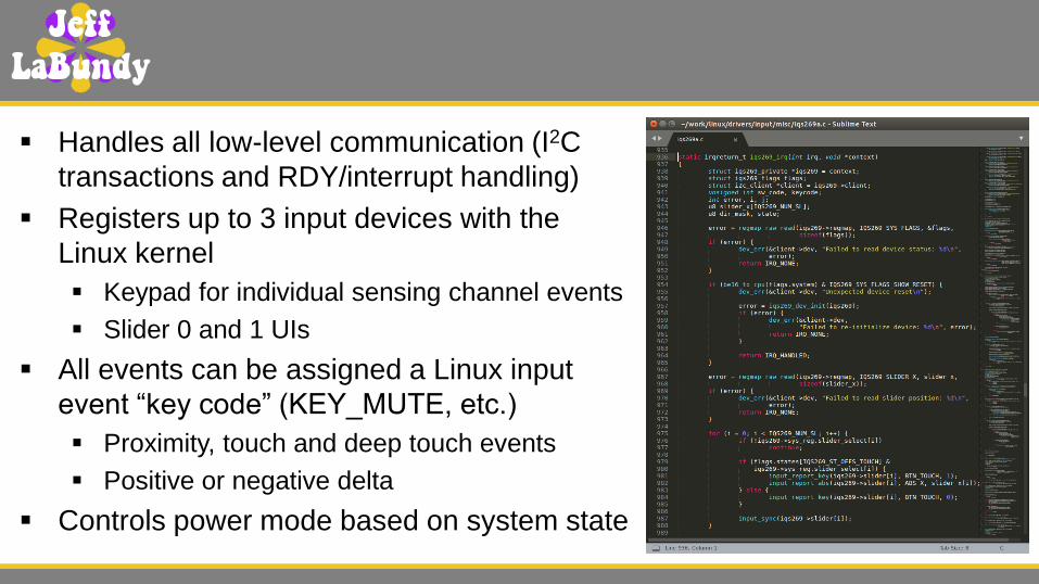
Handles all low-level communication (I2C

transactions and RDY/interrupt handling)

Registers up to 3 input devices with the

Linux kernel

Keypad for individual sensing channel events

Slider 0 and 1 UIs

All events can be assigned a Linux input

event “key code” (KEY_MUTE, etc.)

Proximity, touch and deep touch events

Positive or negative delta

Controls power mode based on system state

Compile-time control of nearly every register

All parameters exposed as device tree

properties

Device tree is a ubiquitous data structure that

describes hardware

All 8 channels represented as fully

configurable device tree child nodes

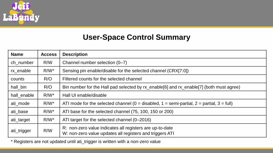
Run-time control of ATI-specific registers

Mirrored to user space through sysfs

attributes (i.e. R/O or R/W “files”)

Facilitates production-line calibration of Hall

sensor

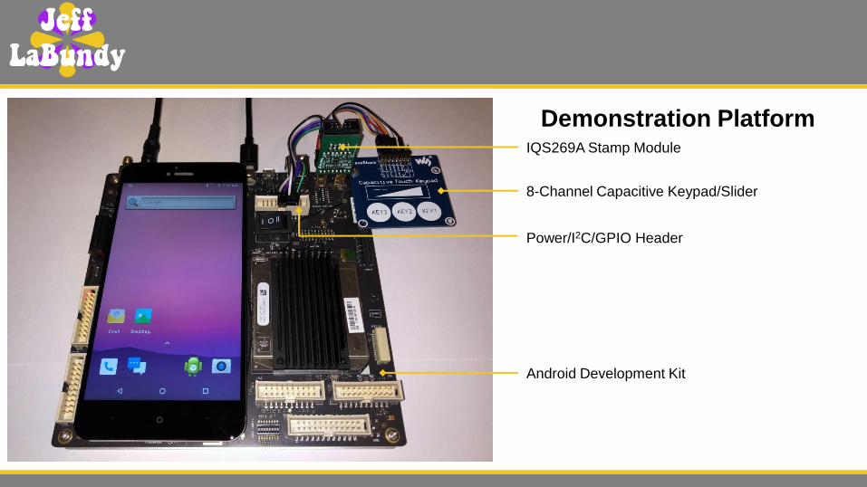
Demonstration Platform

Android Development Kit

IQS269A Stamp Module

Power/I2C/GPIO Header

8-Channel Capacitive Keypad/Slider

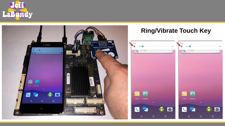
Ring/Vibrate Touch Key

Generic Touch Slider

Slider activity reported using

input event codes commonly

used for axial sliders

EV_KEY: touch start (BTN_TOUCH = 0x014A = 1)

EV_ABS: absolute coordinate change (0–255)

EV_KEY: touch stop (BTN_TOUCH = 0x014A = 0)
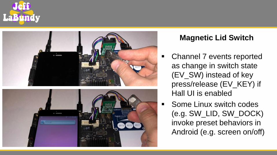
Magnetic Lid Switch

Channel 7 events reported

as change in switch state

(EV_SW) instead of key

press/release (EV_KEY) if

Hall UI is enabled

Some Linux switch codes

(e.g. SW_LID, SW_DOCK)

invoke preset behaviors in

Android (e.g. screen on/off)

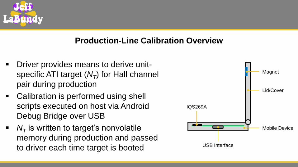
Driver provides means to derive unit-

specific ATI target (NT) for Hall channel

pair during production

Calibration is performed using shell

scripts executed on host via Android

Debug Bridge over USB

NT is written to target’s nonvolatile

memory during production and passed

to driver each time target is booted

Production-Line Calibration Overview

IQS269A

Mobile Device

Lid/Cover

Magnet

USB Interface

1. Set compile-time properties in device tree (see iqs269a.yaml) iqs269a@44 {

[...]

azoteq,hall-enable;

channel@6 { channel@7 {

reg = <0x6>; reg = <0x7>;

azoteq,invert-enable; azoteq,invert-enable;

azoteq,static-enable; azoteq,static-enable;

azoteq,reseed-disable; azoteq,reseed-disable;

azoteq,rx-enable = <0>; azoteq,rx-enable = <0>, <6>;

azoteq,sense-freq = <0x0>; azoteq,sense-freq = <0x0>;

azoteq,sense-mode = <0xE>; azoteq,sense-mode = <0xE>;

azoteq,ati-mode = <0x0>; azoteq,ati-mode = <0x3>;

azoteq,ati-base = <200>; azoteq,ati-base = <200>;

azoteq,ati-target = <320>; azoteq,ati-target = <320>;

event-touch {

linux,code = <SW_LID>;

};

}; };

};

2. Override relevant properties in user space echo 0 > /sys/bus/i2c/devices/1-0044/hall_enable

echo 6 > /sys/bus/i2c/devices/1-0044/ch_number

echo 3 > /sys/bus/i2c/devices/1-0044/ati_mode

echo 7 > /sys/bus/i2c/devices/1-0044/ch_number

echo 3 > /sys/bus/i2c/devices/1-0044/ati_mode

3. Open lid (i.e. remove magnet)

4. Update registers and trigger ATI echo 1 > /sys/bus/i2c/devices/1-0044/ati_trigger

5. Close lid (i.e. apply magnet)

6. Read counts, ATI base/target and Hall pad bin number echo 6 > /sys/bus/i2c/devices/1-0044/ch_number

cat /sys/bus/i2c/devices/1-0044/counts

302

echo 7 > /sys/bus/i2c/devices/1-0044/ch_number

cat /sys/bus/i2c/devices/1-0044/counts

342

cat /sys/bus/i2c/devices/1-0044/ati_base

200

cat /sys/bus/i2c/devices/1-0044/ati_target

320

cat /sys/bus/i2c/devices/1-0044/hall_bin

8

7. Ensure neither inverting nor non-inverting counts reach 8192

8. Calculate ia

9. Calculate NT based on desired counts (e.g. nz = 500)

10. Write NT to channels 6 and 7 echo 6 > /sys/bus/i2c/devices/1-0044/ch_number

echo 454 > /sys/bus/i2c/devices/1-0044/ati_target

echo 7 > /sys/bus/i2c/devices/1-0044/ch_number

echo 454 > /sys/bus/i2c/devices/1-0044/ati_target

11. Open lid (i.e. remove magnet)

12. Update registers and trigger ATI echo 1 > /sys/bus/i2c/devices/1-0044/ati_trigger

13. Close lid (i.e. apply magnet)

14. Read updated counts echo 6 > /sys/bus/i2c/devices/1-0044/ch_number

cat /sys/bus/i2c/devices/1-0044/counts

414

echo 7 > /sys/bus/i2c/devices/1-0044/ch_number

cat /sys/bus/i2c/devices/1-0044/counts

490

15. Ensure channel 7 (EV_SW reporting) counts are reasonably close to nz

16. Write NT to nonvolatile memory (e.g. persist partition)

17. Restore compile-time properties echo 1 > /sys/bus/i2c/devices/1-0044/hall_enable

echo 6 > /sys/bus/i2c/devices/1-0044/ch_number

echo 0 > /sys/bus/i2c/devices/1-0044/ati_mode

echo 7 > /sys/bus/i2c/devices/1-0044/ch_number

echo 3 > /sys/bus/i2c/devices/1-0044/ati_mode

18. Open lid (i.e. remove magnet)

19. Update registers and trigger ATI echo 1 > /sys/bus/i2c/devices/1-0044/ati_trigger

Post-Calibration Boot Sequence

1. Read NT from nonvolatile memory (e.g. persist partition)

2. Write NT to channels 6 and 7 via init.rc echo 6 > /sys/bus/i2c/devices/1-0044/ch_number

echo $NT > /sys/bus/i2c/devices/1-0044/ati_target

echo 7 > /sys/bus/i2c/devices/1-0044/ch_number

echo $NT > /sys/bus/i2c/devices/1-0044/ati_target

3. Update registers and trigger ATI via init.rc echo 1 > /sys/bus/i2c/devices/1-0044/ati_trigger

User-Space Control Summary

Name Access Description

ch_number R/W* Channel number selection (0–7)

rx_enable R/W* Sensing pin enable/disable for the selected channel (CRX[7:0])

counts R/O* Filtered counts for the selected channel

hall_bin R/O* Bin number for the Hall pad selected by rx_enable[6] and rx_enable[7] (both must agree)

hall_enable R/W* Hall UI enable/disable

ati_mode R/W* ATI mode for the selected channel (0 = disabled, 1 = semi-partial, 2 = partial, 3 = full)

ati_base R/W* ATI base for the selected channel (75, 100, 150 or 200)

ati_target R/W* ATI target for the selected channel (0–2016)

ati_trigger R/W* R: non-zero value indicates all registers are up-to-date

W: non-zero value updates all registers and triggers ATI

* Registers are not updated until ati_trigger is written with a non-zero value

LABUNDY.COM


Recommended