86
LOG TRAILER WITH GRAPPLE LOADER T644/1 MACHINE IDENTIFICATION SYMBOL /TYPE: T644/1 SERIAL NUMBER: S Z B 6 4 4 1 X X X
| Date post: | 21-Mar-2018 |
| Category: |
Documents |
| Upload: | nguyendiep |
| View: | 217 times |
| Download: | 1 times |
LOG TRAILER WITH GRAPPLE LOADER
T644/1
MACHINE IDENTIFICATION
SYMBOL /TYPE: T644/1
SERIAL NUMBER: S Z B 6 4 4 1 X X X

INTRODUCTION
Information contained herein is current at date of publication. As a result of improvements,
some numerical values and illustrations contained in this publication may not correspond to
the factual specification of the machine supplied to the user. The manufacturer reserves the
right to introduce design changes in machines produced that facilitate operation and improve
the quality of their work, without making minor amendments to these operating instructions.
Please send comments and observations on the subject of the design and operation of the
machine to the manufacturer. This information enables objective evaluation of the machines
produced and provides indications for their further modernisation. Information on significant
design changes are passed on to users with the aid of the information insert attached to
these operating instructions (annexes).
The operating instructions are an integral part of the machine's documentation. Before using
the tractor, the user must familiarise himself with the content of these instructions and
observe all recommendations. This guarantees safe operation and ensures malfunction free
work of the machine. The machine is designed to meet obligatory standards, documents and
legal regulations currently in force.
The instructions describe the basic principles of safe use and operation of T644/1 log trailer
with grapple loader. If the information contained in the operating instructions needs
clarification then the user should refer for assistance to the sale point where the machine was
purchased or to the manufacturer.
Manufacturer's address:
PRONAR Sp. z o.o.
ul. Mickiewicza 101A
17-210 Narew
Contact telephones
+48 85 681 63 29 +48 85 681 64 29
+48 85 681 63 81 +48 85 681 63 82
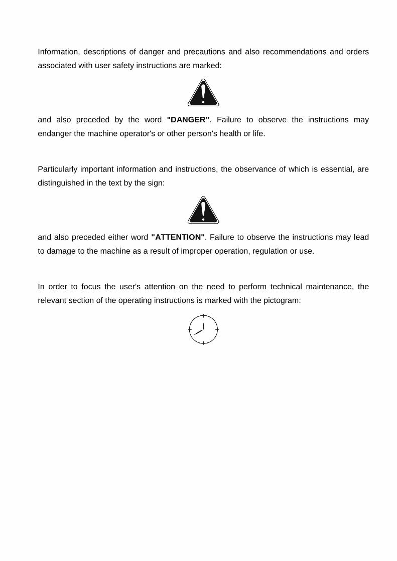
Information, descriptions of danger and precautions and also recommendations and orders
associated with user safety instructions are marked:
and also preceded by the word "DANGER” . Failure to observe the instructions may
endanger the machine operator's or other person's health or life.
Particularly important information and instructions, the observance of which is essential, are
distinguished in the text by the sign:
and also preceded either word "ATTENTION" . Failure to observe the instructions may lead
to damage to the machine as a result of improper operation, regulation or use.
In order to focus the user's attention on the need to perform technical maintenance, the
relevant section of the operating instructions is marked with the pictogram:

TABLE OF CONTENTS
1 BASIC INFORMATION 1.1 1.1 IDENTIFICATION 1.2 1.2 INTENDED USE 1.3 1.3 FITTINGS 1.5 1.4 WARRANTY CONDITIONS 1.5 1.5 TRANSPORT 1.7 1.6 ENVIRONMENTAL HAZARDS 1.7 1.7 WITHDRAWAL FROM USE 1.8
2 SAFETY IN USE 2.1 2.1 BASIC SAFETY PRINCIPLES 2.2 2.2 PRINCIPLES WHEN TRAVELLING ON PUBLIC ROADS 2.7 2.3 DESCRIPTION OF MINIMAL RISK 2.8 2.4 INFORMATION AND WARNING STICKERS 2.9
3 CONSTRUCTION AND PRINCIPLE OF OPERATION 3.1 3.1 TECHNICAL SPECIFICATION 3.2 3.2 LOAD BOX 3.3 3.3 LOADER 3.4 3.4 AXLE SYSTEM 3.6 3.5 ELECTRICAL SYSTEM, WARNING SIGNS AND INDICATORS 3.7 3.6 WORKING BRAKE 3.8 3.7 CENTRAL HYDRAULIC SYSTEM 3.12 3.8 FRAME EXTENSION HYDRAULIC SYSTEM 3.18 3.9 POWER STEERING HYDRAULIC SYSTEM 3.19
4 CORRECT USE 4.1 4.1 PREPARING FOR WORK BEFORE FIRST USE 4.2 4.2 CHECKING THE TRAILER'S TECHNICAL CONDITION 4.3 4.3 ATTACHING TO TRACTOR 4.5 4.4 RELOADING WORK 4.6 4.5 TRANSPORTING THE TRAILER 4.10
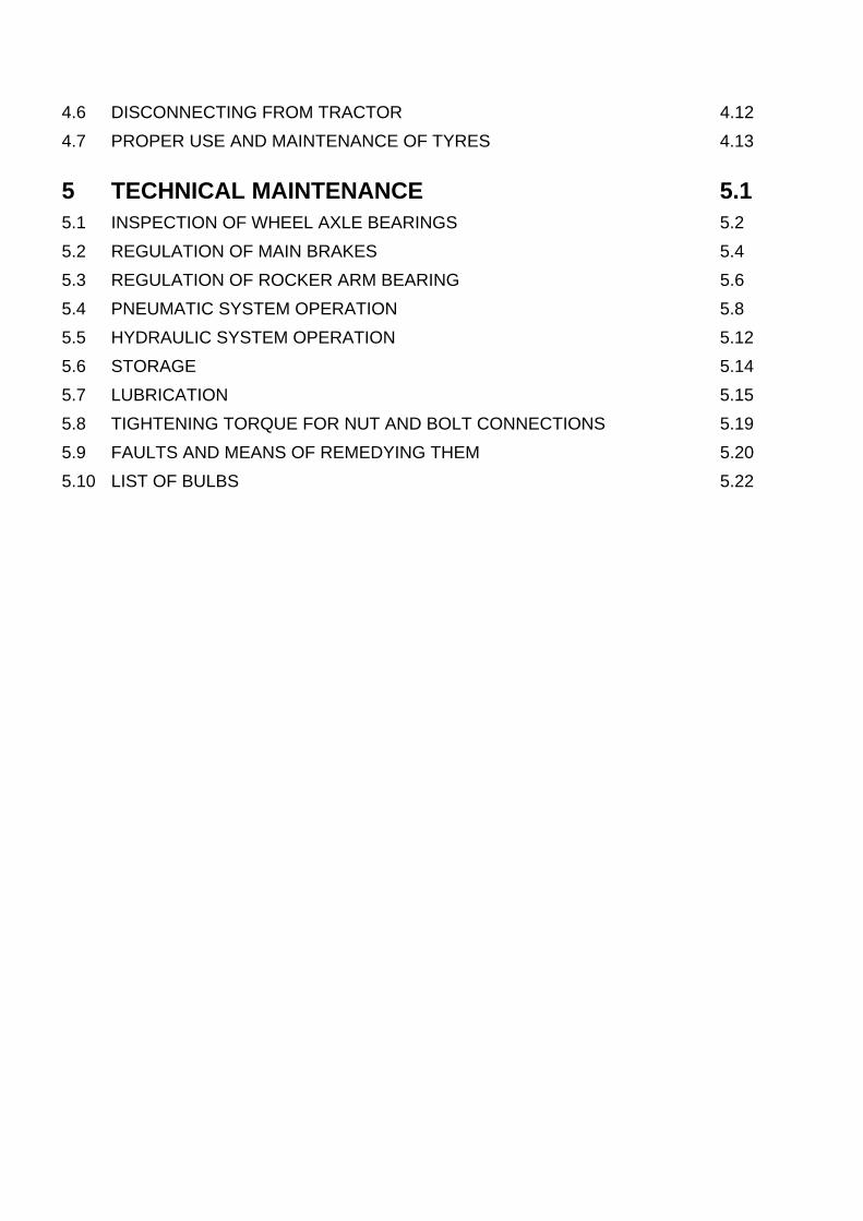
4.6 DISCONNECTING FROM TRACTOR 4.12 4.7 PROPER USE AND MAINTENANCE OF TYRES 4.13
5 TECHNICAL MAINTENANCE 5.1 5.1 INSPECTION OF WHEEL AXLE BEARINGS 5.2 5.2 REGULATION OF MAIN BRAKES 5.4 5.3 REGULATION OF ROCKER ARM BEARING 5.6 5.4 PNEUMATIC SYSTEM OPERATION 5.8 5.5 HYDRAULIC SYSTEM OPERATION 5.12 5.6 STORAGE 5.14 5.7 LUBRICATION 5.15 5.8 TIGHTENING TORQUE FOR NUT AND BOLT CONNECTIONS 5.19 5.9 FAULTS AND MEANS OF REMEDYING THEM 5.20 5.10 LIST OF BULBS 5.22
1.1
SECTION
1 BASIC INFORMATION
IDENTIFICATION
INTENDED USE
FITTINGS
WARRANTY CONDITIONS
TRANSPORT
ENVIRONMENTAL HAZARDS
WITHDRAWAL FROM USE
1.2
1.1 IDENTIFICATION
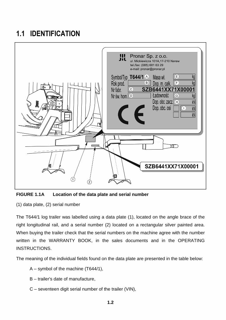
FIGURE 1.1A Location of the data plate and serial n umber
(1) data plate, (2) serial number
The T644/1 log trailer was labelled using a data plate (1), located on the angle brace of the
right longitudinal rail, and a serial number (2) located on a rectangular silver painted area.
When buying the trailer check that the serial numbers on the machine agree with the number
written in the WARRANTY BOOK, in the sales documents and in the OPERATING
INSTRUCTIONS.
The meaning of the individual fields found on the data plate are presented in the table below:
A – symbol of the machine (T644/1),
B – trailer's date of manufacture,
C – seventeen digit serial number of the trailer (VIN),
1.3
D – official certificate number (not applicable),
E – tare weight of the trailer,
F – maximum gross weight,
G – capacity,
H – maximum hitch load (vertical load),
I – maximum vehicle axle load.
The serial number and type of the axle shaft is stamped on the data plate riveted to the beam
of the axle shaft.
1.2 INTENDED USE
The T644/1 log trailer with grapple loader is intended as a towed agricultural machine,
designed to be connected to and used with an agricultural tractor.
The T644/1 is designed for rolling and carrying wood logs. Rolling involves loading wood
using the grapple of the foreloader from the place in the forest where it is logged (from
thinning, clearing or other types of logging) onto the loading area of the trailer, delineated
with stakes. By carrying is meant transporting wood loaded onto the trailer to the place where
it is unloaded.
The trailer may be towed on public roads provided the detailed requirements of a given
country's legislation are fulfilled.
The trailer must not be used in any way other than that described above. Using it as intended
also involves all actions connected with the safe and proper operation and maintenance of
the machine.
Due to the above, the user is obliged to:
• familiarise himself with the contents of the OPERATING INSTRUCTIONS and
comply with them,
• understand the operating principle of the trailer and of its safe and proper use,
• comply with general safety regulations while working,
• prevent accidents,
• comply with road traffic regulations.
1.4
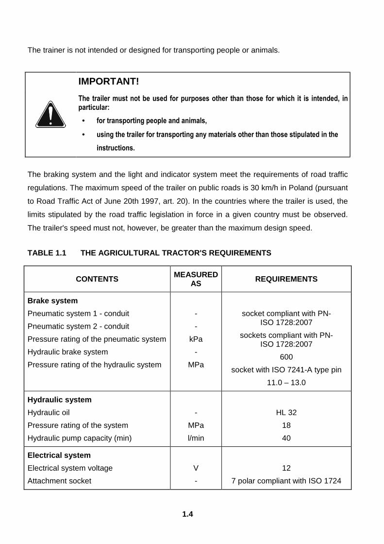
The trainer is not intended or designed for transporting people or animals.
IMPORTANT!
The trailer must not be used for purposes other than those for which it is intended, in particular:
• for transporting people and animals,
• using the trailer for transporting any materials other than those stipulated in the
instructions.
The braking system and the light and indicator system meet the requirements of road traffic
regulations. The maximum speed of the trailer on public roads is 30 km/h in Poland (pursuant
to Road Traffic Act of June 20th 1997, art. 20). In the countries where the trailer is used, the
limits stipulated by the road traffic legislation in force in a given country must be observed.
The trailer's speed must not, however, be greater than the maximum design speed.
TABLE 1.1 THE AGRICULTURAL TRACTOR'S REQUIREMENTS
CONTENTS MEASURED AS REQUIREMENTS
Brake system
Pneumatic system 1 - conduit
Pneumatic system 2 - conduit
Pressure rating of the pneumatic system
Hydraulic brake system
Pressure rating of the hydraulic system
-
-
kPa
-
MPa
socket compliant with PN-ISO 1728:2007
sockets compliant with PN-ISO 1728:2007
600
socket with ISO 7241-A type pin
11.0 – 13.0
Hydraulic system
Hydraulic oil
Pressure rating of the system
Hydraulic pump capacity (min)
-
MPa
l/min
HL 32
18
40
Electrical system
Electrical system voltage
Attachment socket
V
-
12
7 polar compliant with ISO 1724
1.5
CONTENTS MEASURED AS REQUIREMENTS
Tractor hitches
Minimum vertical load capacity of hitch
-
kg
2 000
Other requirements
Minimum power demand
kW / KM
47.7 / 65
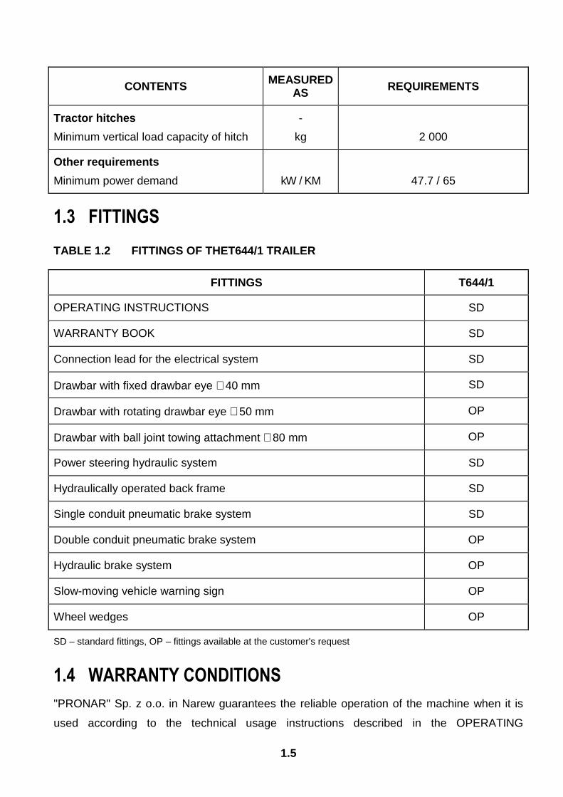
1.3 FITTINGS
TABLE 1.2 FITTINGS OF THET644/1 TRAILER
FITTINGS T644/1
OPERATING INSTRUCTIONS SD
WARRANTY BOOK SD
Connection lead for the electrical system SD
Drawbar with fixed drawbar eye ∅40 mm SD
Drawbar with rotating drawbar eye ∅50 mm OP
Drawbar with ball joint towing attachment ∅80 mm OP
Power steering hydraulic system SD
Hydraulically operated back frame SD
Single conduit pneumatic brake system SD
Double conduit pneumatic brake system OP
Hydraulic brake system OP
Slow-moving vehicle warning sign OP
Wheel wedges OP
SD – standard fittings, OP – fittings available at the customer's request
1.4 WARRANTY CONDITIONS
"PRONAR" Sp. z o.o. in Narew guarantees the reliable operation of the machine when it is
used according to the technical usage instructions described in the OPERATING
1.6
INSTRUCTIONS. Faults discovered during the warranty period will be rectified by the
Warranty Service within no more than 14 working days of the machine being received for
repair by the Warranty Service, or within another agreed time.
The guarantee does not cover those parts and sub-assemblies of the machine which are
subject to wear in normal usage conditions, regardless of the warranty period. The warranty
service only applies to such cases as: mechanical damage which is not the user's fault,
factory defects of parts, etc. Consumables include the following parts/sub-assemblies:
• tyres,
• brake pads,
• bulbs.
In the event of damage arising from:
• mechanical damage which is the user's fault, caused by road accidents,
• by inappropriate use, regulation or maintenance, use of the trailer for purposes
other than those for which it is intended,
• use of a damaged trailer,
• repairs carried out by unauthorised persons, improperly carried out repairs,
• arbitrary and wilful adjustments to the trailer's structure,
the user may lose the right to warranty service.
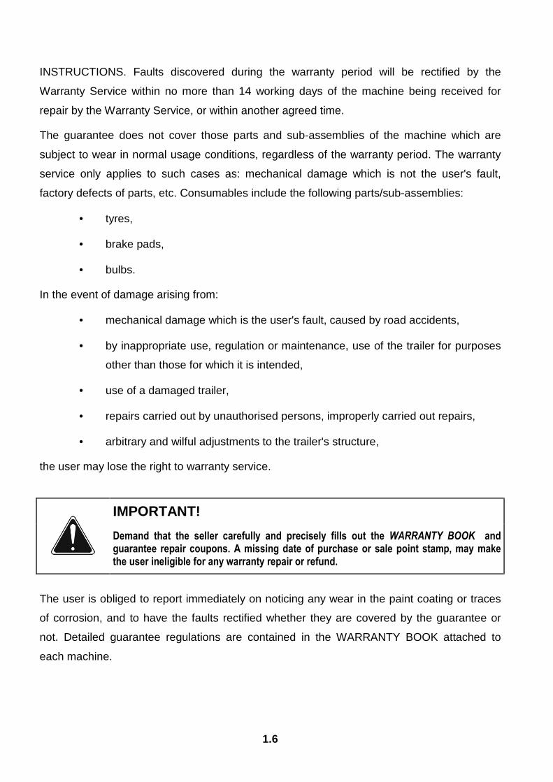
IMPORTANT!
Demand that the seller carefully and precisely fills out the WARRANTY BOOK and guarantee repair coupons. A missing date of purchase or sale point stamp, may make the user ineligible for any warranty repair or refund.
The user is obliged to report immediately on noticing any wear in the paint coating or traces
of corrosion, and to have the faults rectified whether they are covered by the guarantee or
not. Detailed guarantee regulations are contained in the WARRANTY BOOK attached to
each machine.

1.7
1.5 TRANSPORT
The trailer is ready for sale in a completely assembled state and does not require packing.
Packing is only required for the machine's technical and driving documentation, connection
lead for the electrical system and any extra fittings.
IMPORTANT!
When transporting independently, the user must familiarise himself with the content of these instructions and observe their recommendations. When being transported on a motor vehicle the trailer must be mounted on the vehicle's platform in accordance with the transport safety requirements. The driver of the vehicle should take particular care while driving. This is due to the vehicle's centre of gravity shifting upwards when loaded with the machine.
The trailer is delivered to the user either transported on a vehicle or, after being attached to a
tractor, independently (towed). In the case of independent (towed) delivery, the "slow moving
vehicle" plaque should be attached. The towing speed should be adapted to the current road
conditions, but must not be greater than the maximum design speed. The machine may sway
when being towed. Should this happen, the driving speed should be decreased.
When loading and unloading the trailer, comply with the general principles of workplace
health and safety for reloading work. Persons operating reloading equipment must have the
qualifications required to operate these machines.
The trailer should be attached firmly to the platform of the vehicle using straps or chains fitted
with a tightening mechanism. The fastening equipment used must have a valid safety
certificate. Wedges or other objects without sharp edges should be placed under the wheels
of the trailer to prevent it from rolling. The wedges must be fixed to the platform of the
vehicle. During reloading work, particular care should be taken not to damage parts of the
machine's fittings or the lacquer coating.
1.6 ENVIRONMENTAL HAZARDS
A hydraulic oil leak constitutes a direct threat to the natural environment owing to its limited
biodegradability. While carrying out maintenance and repair work which involves the risk of
an oil leak, this work should take place on an oil resistant floor or surface. In the event of oil
leaking into the environment, first of all safeguard the source of the leak, and then remove
1.8
the leaked oil using available means. Remaining oil should be removed using sorbents, or by
mixing the oil with sand, sawdust or other absorbent materials. The oil pollution, once
gathered up, should be kept in a sealed, marked, hydrocarbon resistant container, and then
passed on to the appropriate oil waste recycling centre. The container should be kept away
from heat sources, flammable materials and food.
Oil which has been used up or is unsuitable for further use owing to a loss of its properties
should be stored in its original packaging in the conditions described above.
1.7 WITHDRAWAL FROM USE
Should the user decide to withdraw the machine fro use, the entire trailer should be taken to
a scrap yard. When spare parts are changed, worn out or damaged parts should be taken to
a collection point for recyclable raw materials. Hydraulic oil should be taken to the
appropriate facility dealing with the re-use of this type of waste.
2.1
SECTION
2 SAFETY IN USE
BASIC SAFETY PRINCIPLES PRINCIPLES WHEN TRAVELLING ON PUBLIC ROADS DESCRIPTION OF MINIMAL RISK INFORMATION AND WARNING STICKERS

2.2
2.1 BASIC SAFETY PRINCIPLES • Before using the trailer, the user must thoroughly familiarise himself with the
content of these instructions. While using it, follow all the recommendations
contained in them.
• The trailer may only be used and operated by persons qualified to drive
agricultural tractors and trained in the use of the machine.
• If the information contained in the operating instructions is difficult to
understand, contact a seller who runs an authorised technical service on behalf
of the manufacturer, or contact the manufacturer directly.
• Careless and improper use and operation of the trailer, and non-adherence to
the recommendations included in these instructions are dangerous for the
health.
• Be warned that a minimal risk does exist, and for this reason the fundamental
basis for using this machine should be the application of safety principles and
sensible behaviour.
• The trailer must never be used by persons who are not authorised to drive
agricultural tractors, including children and people under the influence of alcohol
or other drugs.
• Non-adherence to the principles of safe use creates a danger for the health and
life of the operator and others.
• The trailer must not be used for purposes other than those for which it is
intended. Anyone who uses the machine other than the way intended takes full
responsibility on himself for any consequences of this use. Use other than
intended means using the machine in any way other than that specified in the
operating instructions.
• Any modification to the trailer frees PRONAR Narew from any responsibility for
damage or detriment to health which may arise as a result.
• Before using the trailer always check its technical condition, especially in terms
of safety. In particular, check the technical condition of the hitch system, the
2.3
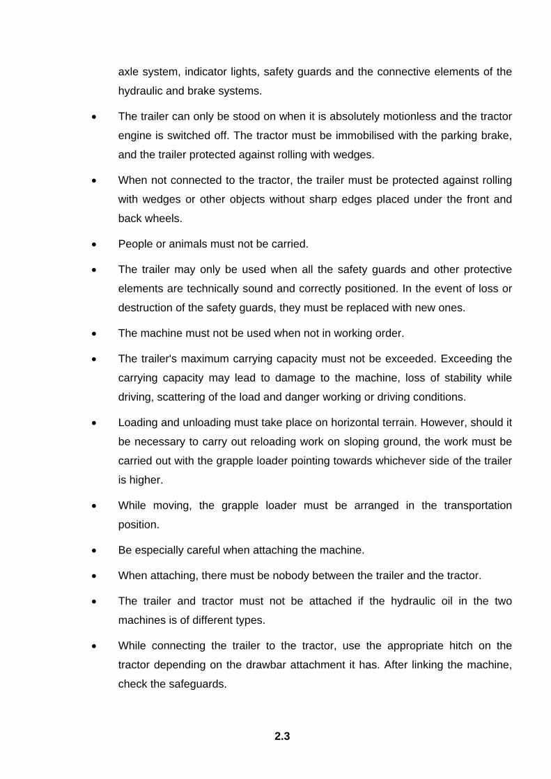
axle system, indicator lights, safety guards and the connective elements of the
hydraulic and brake systems.
• The trailer can only be stood on when it is absolutely motionless and the tractor
engine is switched off. The tractor must be immobilised with the parking brake,
and the trailer protected against rolling with wedges.
• When not connected to the tractor, the trailer must be protected against rolling
with wedges or other objects without sharp edges placed under the front and
back wheels.
• People or animals must not be carried.
• The trailer may only be used when all the safety guards and other protective
elements are technically sound and correctly positioned. In the event of loss or
destruction of the safety guards, they must be replaced with new ones.
• The machine must not be used when not in working order.
• The trailer's maximum carrying capacity must not be exceeded. Exceeding the
carrying capacity may lead to damage to the machine, loss of stability while
driving, scattering of the load and danger working or driving conditions.
• Loading and unloading must take place on horizontal terrain. However, should it
be necessary to carry out reloading work on sloping ground, the work must be
carried out with the grapple loader pointing towards whichever side of the trailer
is higher.
• While moving, the grapple loader must be arranged in the transportation
position.
• Be especially careful when attaching the machine.
• When attaching, there must be nobody between the trailer and the tractor.
• The trailer and tractor must not be attached if the hydraulic oil in the two
machines is of different types.
• While connecting the trailer to the tractor, use the appropriate hitch on the
tractor depending on the drawbar attachment it has. After linking the machine,
check the safeguards.

2.4
• The arrangement of the load may not cause an overload on the axle or hitch
system of the trailer or tractor.
• The hydraulic system is under high pressure when operating.
• Regularly check the technical condition of the connections and the hydraulic
and pneumatic leads.
• In the event of a fault in the hydraulic or pneumatic system, disconnect the
trailer from use until the fault has been fixed. There must not be any leaks of
hydraulic oil.
• When connecting the hydraulic conduits to the tractor, make sure that the
hydraulic systems of the tractor and trailer are not under pressure.
• Reduce the oil or air pressure in the trailer before dismantling the hydraulic or
pneumatic elements.
• In the event of injuries being caused by pressurised hydraulic oil, contact a
doctor immediately. Hydraulic oil may find its way under the skin and cause
infections.
• Use the hydraulic oil recommended by the manufacturer. Never mix two types
of oil.
• After changing the hydraulic oil, the used oil should be properly disposed of.
• When working on the tyres, wedges or other objects without sharp edges
should be placed under the wheels of the trailer to prevent it from rolling.
• Repair work on the wheels or tyres should be carried out by persons trained
and entitled to do so. This work should be carried out using appropriately
selected tools.
• After removing a wheel, always check how firmly the nuts are screwed in.
Individual checks should be made after the first use, after the first journey with a
load, after travelling 1000 km and then every 6 months. The above actions
should be repeated individually if a wheel has been removed from the wheel
axle.
• Loading and unloading work should be carried out by someone experienced in
forestry work.
2.5
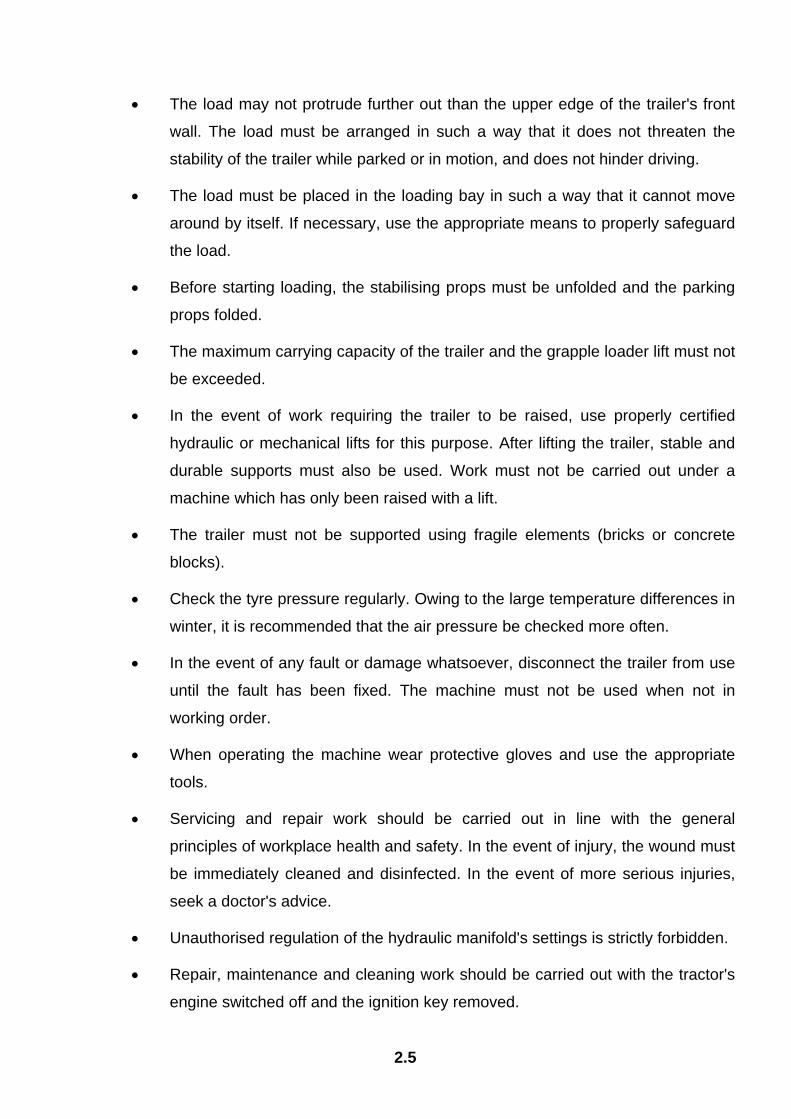
• The load may not protrude further out than the upper edge of the trailer's front
wall. The load must be arranged in such a way that it does not threaten the
stability of the trailer while parked or in motion, and does not hinder driving.
• The load must be placed in the loading bay in such a way that it cannot move
around by itself. If necessary, use the appropriate means to properly safeguard
the load.
• Before starting loading, the stabilising props must be unfolded and the parking
props folded.
• The maximum carrying capacity of the trailer and the grapple loader lift must not
be exceeded.
• In the event of work requiring the trailer to be raised, use properly certified
hydraulic or mechanical lifts for this purpose. After lifting the trailer, stable and
durable supports must also be used. Work must not be carried out under a
machine which has only been raised with a lift.
• The trailer must not be supported using fragile elements (bricks or concrete
blocks).
• Check the tyre pressure regularly. Owing to the large temperature differences in
winter, it is recommended that the air pressure be checked more often.
• In the event of any fault or damage whatsoever, disconnect the trailer from use
until the fault has been fixed. The machine must not be used when not in
working order.
• When operating the machine wear protective gloves and use the appropriate
tools.
• Servicing and repair work should be carried out in line with the general
principles of workplace health and safety. In the event of injury, the wound must
be immediately cleaned and disinfected. In the event of more serious injuries,
seek a doctor's advice.
• Unauthorised regulation of the hydraulic manifold's settings is strictly forbidden.
• Repair, maintenance and cleaning work should be carried out with the tractor's
engine switched off and the ignition key removed.
2.6
• Regularly check the condition of the screw and nut connections.
• Before welding or electrical work, the trailer should be disconnected from the
power supply. The paint coating should be cleaned. Burning paint fumes are
poisonous for people and animals. Welding work should be carried out in a well
lit and well ventilated space.
• During welding work pay attention to flammable or fusible elements (parts of the
pneumatic, electric and hydraulic systems, plastic parts). If there is a risk that
they will catch fire or be damaged, they should be removed or covered with
non-flammable material before commencing welding work.
• During the warranty period, any repairs may only be carried out by a Warranty
Service authorised by the manufacturer.
• Should it be necessary to change individual parts, use only those parts
indicated by the manufacturer. Non-adherence to these requirements may
cause danger to the health and the user's and other people's lives, and also
damage the machine.
• After completing work connected with greasing, remove excess oil or grease.
• Before activating the trailer, always ensure that all the safety guards are in good
condition and in place. Damaged or incomplete sub-assemblies must be
exchanged for original new ones.

2.7
2.2 PRINCIPLES WHEN TRAVELLING ON PUBLIC ROADS • When travelling on public roads, respect the road traffic regulations.
FIGURE 2.1A Positioning the warning sign
(1) slow-moving vehicle sign
• Exceeding the maximum load capacity of the trailer may damage it, and also
threaten the safety of traffic.
• Do not exceed the maximum speed limit. Adjust your speed to the road
conditions.
• Place the slow-moving vehicle warning sign on the back wall.
• While driving on public roads the trailer must be fitted with a certified or
authorised reflective warning triangle.
• While moving without a load, the grapple loader and grab must be arranged in
the transportation position.
1

2.8
• A load protruding beyond the edge of the trailer should be indicated according
to the road traffic regulations applicable in the country where the trailer is being
used.
• When driving on public roads, drawbar rotation hydraulic system must not be
used. Drawbar must be positioned on a symmetry plane and blocked.
2.3 DESCRIPTION OF MINIMAL RISK Pronar Sp. z o. o. in Narew has made every effort to eliminate the risk of accidents. There is,
however, a certain minimal risk which could lead to an accident, and this is connected mainly
with the actions described below:
• using the trailer for purposes other than those for which it is intended,
• being between the tractor and the trailer while the engine is running and when
the machine is being attached,
• being on the machine while the engine is running,
• being within range of the grapple loader, being positioned under the grapple
loader,
• operating the trailer with the safety guards removed or faulty,
• not keeping a safe distance while the trailer is in operation,
• not keeping a safe distance during reloading work,
• operation of the trailer by persons under the influence of alcohol,
• cleaning, maintenance and technical checks of the trailer.
The minimal risk may be kept to a minimum by following the recommendations below:
• prudent and unhurried operation of the machine,
• sensible application of the remarks and recommendations contained in the
operating instructions,
• keeping a safe distance from forbidden or dangerous places,
• a ban on being on the machine when it is operating,
• a ban on being under the grapple loader while the trailer is in operation,

2.9
• carrying out repair and maintenance work in line with operating safety
principles,
• carrying out repair and maintenance work by persons trained to do so,
• using strictly suited protective clothing,
• ensuring unauthorised persons have no access to the machine, especially
children.
2.4 INFORMATION AND WARNING STICKERS The trailer is labelled with the information and warning stickers mentioned in table (2.1). The
symbols are positioned as presented in figures (2.2A) and (2.3A). Throughout the time it is in
use, the user of the machine is obliged to take care that notices and warning and information
symbols located on the trailer are clear and legible. In the event of their destruction, they
must be replaced with new ones. Stickers with notices and symbols are available from the
manufacturer, or from the retailer where the machine was purchased. New assemblies,
changed during repair, must be labelled once again with the appropriate safety signs.
TABLE 2.1 INFORMATION AND WARNING STICKERS
ITEM SAFETY SYMBOL DESCRIPTION
1
Trailer control information sticker.
2
Keep a safe distance from the trailer when the loader is in
operation.
2.10
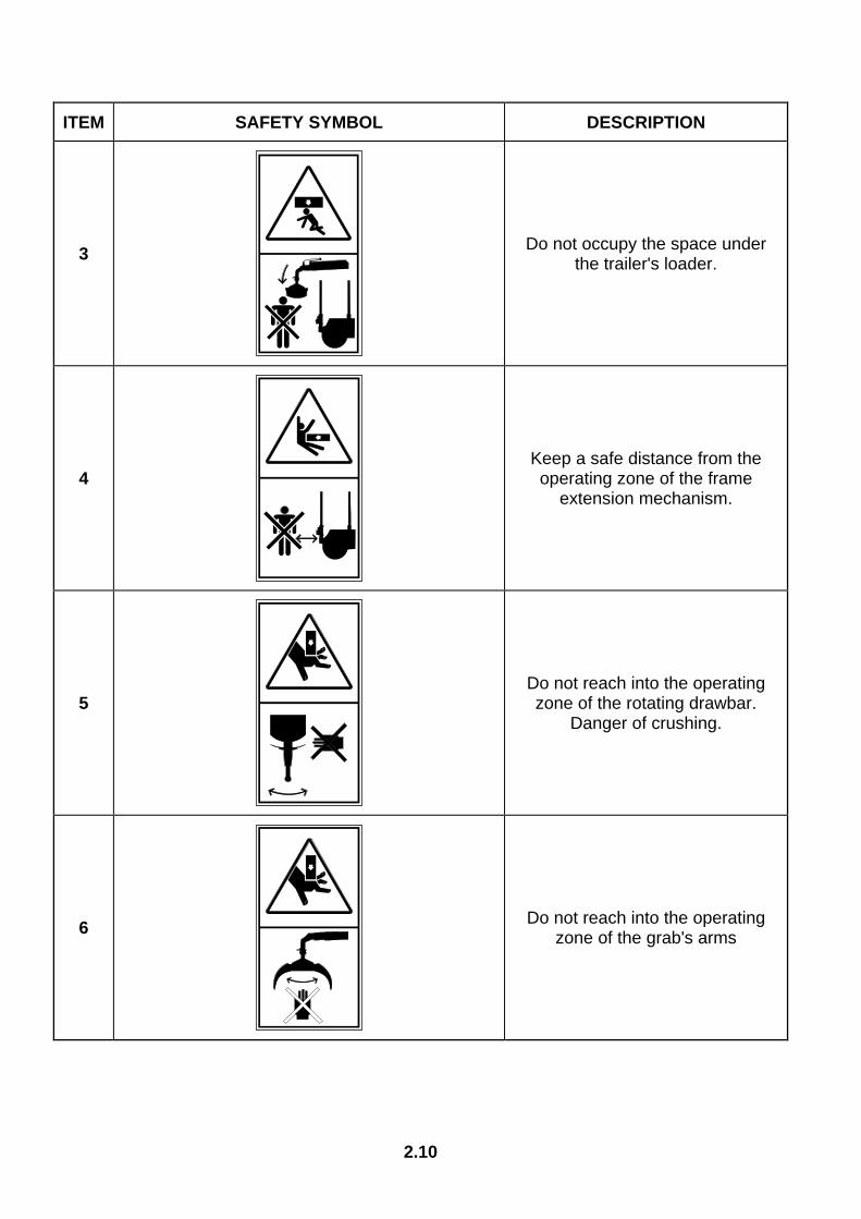
ITEM SAFETY SYMBOL DESCRIPTION
3
Do not occupy the space under the trailer's loader.
4
Keep a safe distance from the operating zone of the frame
extension mechanism.
5
Do not reach into the operating zone of the rotating drawbar.
Danger of crushing.
6
Do not reach into the operating zone of the grab's arms
2.11
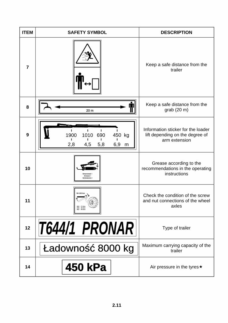
ITEM SAFETY SYMBOL DESCRIPTION
7
Keep a safe distance from the trailer
8
Keep a safe distance from the grab (20 m)
9
Information sticker for the loader lift depending on the degree of
arm extension
10
Grease according to the recommendations in the operating
instructions
11
Check the condition of the screw and nut connections of the wheel
axles
12
Type of trailer
13
Maximum carrying capacity of the trailer
14
Air pressure in the tyres
20 m
1900
2,8
1010
4,5
690
5,8
450 kg
6,9 m
Smarować ! Grease !Schmieren !
50-100 km
M18 27 kGmM20 35 kGmM22 45 kGm
T644/1 PRONARŁadowność 8000 kg
450 kPa

2.12
ITEM SAFETY SYMBOL DESCRIPTION
15
Before beginning servicing or repairs, switch off engine and
remove key from ignition
16
Before starting work, familiarise yourself with the contents of the OPERATING INSTRUCTIONS.
17
Quick couplers of the hydraulic system of the frame
extension.
18
Quick coupler of the hydraulic brake system.
19
Quick couplers of the hydraulic system of the drawbar rotation.
- tyre pressure in standard fittings, pressure levels may be subject to change depending on the tyres used
- Information stickers numbers (17), (18) and (19) were placed on the hydraulic leads depending on the
type of system.

2.13
FIGURE 2.2A Distribution of information and warning stickers, pt. 1
Labelling in line with table 2.1.
3642

2.14
FIGURE 2.3A Distribution of information and warning stickers, pt. 2
Labelling in line with table 2.1.
Łado
wno
ść 8
000
kg
Sm
aro
wać !
G
rease !
Sch
mie
ren
!
ROR
PNA
4T6
4/1
5
450 k
Pa
1900 2,8
1010 4,5
690
5,8
450
kg
7,0
m
1516
1314
10 11
128
9
1
20 m
T644
/1 P
RONA
R
50
-10
0 k
m
M1
8
2
7 k
Gm
M2
0
3
5 k
Gm
M2
2
4
5 k
Gm

3.1
SECTION
3 CONSTRUCTION AND
PRINCIPLE OF
OPERATION
TECHNICAL SPECIFICATION
LOAD BOX
LOADER
AXLE SYSTEM
ELECTRICAL SYSTEM, WARNING SIGNS AND INDICATORS
WORKING BRAKE
CENTRAL HYDRAULIC SYSTEM
3.2
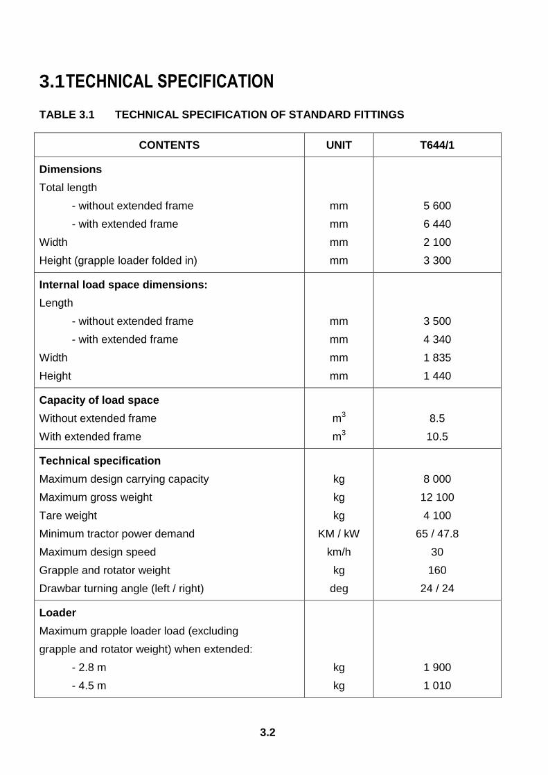
3.1 TECHNICAL SPECIFICATION
TABLE 3.1 TECHNICAL SPECIFICATION OF STANDARD FITTINGS
CONTENTS UNIT T644/1
Dimensions
Total length
- without extended frame
- with extended frame
Width
Height (grapple loader folded in)
mm
mm
mm
mm
5 600
6 440
2 100
3 300
Internal load space dimensions:
Length
- without extended frame
- with extended frame
Width
Height
mm
mm
mm
mm
3 500
4 340
1 835
1 440
Capacity of load space
Without extended frame
With extended frame
m3
m3
8.5
10.5
Technical specification
Maximum design carrying capacity
Maximum gross weight
Tare weight
Minimum tractor power demand
Maximum design speed
Grapple and rotator weight
Drawbar turning angle (left / right)
kg
kg
kg
KM / kW
km/h
kg
deg
8 000
12 100
4 100
65 / 47.8
30
160
24 / 24
Loader
Maximum grapple loader load (excluding
grapple and rotator weight) when extended:
- 2.8 m
- 4.5 m
kg
kg
1 900
1 010
3.3
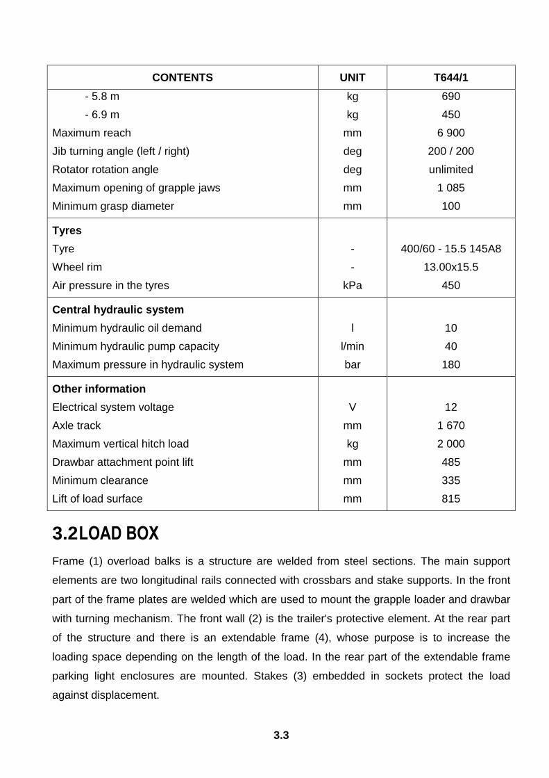
CONTENTS UNIT T644/1
- 5.8 m
- 6.9 m
Maximum reach
Jib turning angle (left / right)
Rotator rotation angle
Maximum opening of grapple jaws
Minimum grasp diameter
kg
kg
mm
deg
deg
mm
mm
690
450
6 900
200 / 200
unlimited
1 085
100
Tyres
Tyre
Wheel rim
Air pressure in the tyres
-
-
kPa
400/60 - 15.5 145A8
13.00x15.5
450
Central hydraulic system
Minimum hydraulic oil demand
Minimum hydraulic pump capacity
Maximum pressure in hydraulic system
l
l/min
bar
10
40
180
Other information
Electrical system voltage
Axle track
Maximum vertical hitch load
Drawbar attachment point lift
Minimum clearance
Lift of load surface
V
mm
kg
mm
mm
mm
12
1 670
2 000
485
335
815
3.2 LOAD BOX
Frame (1) overload balks is a structure are welded from steel sections. The main support
elements are two longitudinal rails connected with crossbars and stake supports. In the front
part of the frame plates are welded which are used to mount the grapple loader and drawbar
with turning mechanism. The front wall (2) is the trailer's protective element. At the rear part
of the structure and there is an extendable frame (4), whose purpose is to increase the
loading space depending on the length of the load. In the rear part of the extendable frame
parking light enclosures are mounted. Stakes (3) embedded in sockets protect the load
against displacement.
3.4
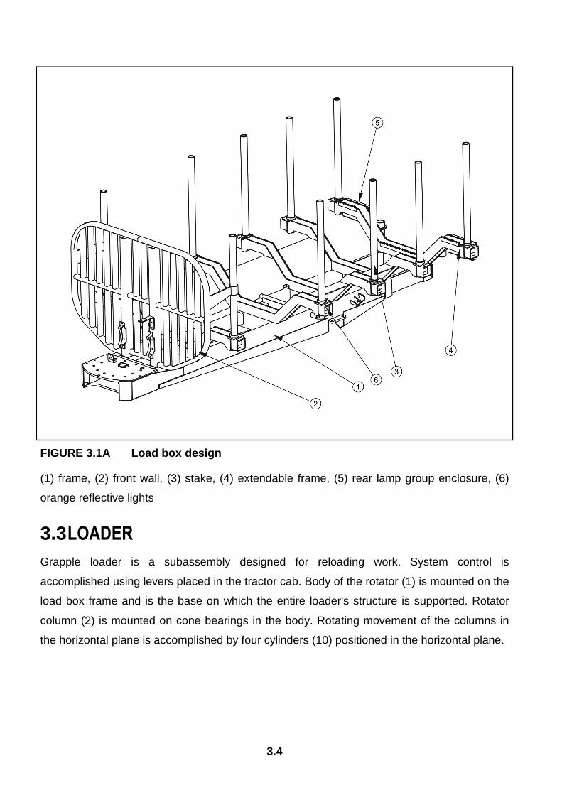
FIGURE 3.1A Load box design
(1) frame, (2) front wall, (3) stake, (4) extendable frame, (5) rear lamp group enclosure, (6)
orange reflective lights
3.3 LOADER
Grapple loader is a subassembly designed for reloading work. System control is
accomplished using levers placed in the tractor cab. Body of the rotator (1) is mounted on the
load box frame and is the base on which the entire loader's structure is supported. Rotator
column (2) is mounted on cone bearings in the body. Rotating movement of the columns in
the horizontal plane is accomplished by four cylinders (10) positioned in the horizontal plane.
3.5
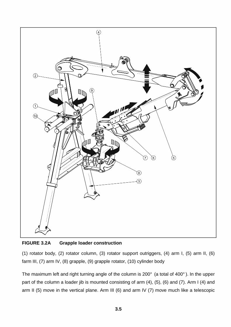
FIGURE 3.2A Grapple loader construction
(1) rotator body, (2) rotator column, (3) rotator support outriggers, (4) arm I, (5) arm II, (6)
farm III, (7) arm IV, (8) grapple, (9) grapple rotator, (10) cylinder body
The maximum left and right turning angle of the column is 200° (a total of 400° ). In the upper
part of the column a loader jib is mounted consisting of arm (4), (5), (6) and (7). Arm I (4) and
arm II (5) move in the vertical plane. Arm III (6) and arm IV (7) move much like a telescopic

3.6
cylinder. Mounted at the end of the jib is cylinder's suspension, grapple rotator (9) and the
grapple (8). Specially designed grapple rotator allows turning of the grapple in both
directions, and the rotating angle is unlimited.
Mounted on both sides of the rotator's body (1) are support outriggers (3), whose purpose is
to stabilise the trailer during reloading work. Outriggers are expanded using cylinders placed
inside the guide rail.
3.4 AXLE SYSTEM
FIGURE 3.3A Axle system design
(1) wheel, (2) rocker arm, (3) axle shaft, (4) Axel, (5) arm of the axle shaft expander cam
Suitable trailer tyres and axle system design allow efficient driving in difficult terrain
conditions. Subassembly is mounted in the rear section of the load box frame. Axle shaft (3)
consisting of square bar terminated with a pin, were mounted on cone bearings are wheel
hubs. These are single wheels, equipped with shoe breaks activated through mechanical
expander cams. Axle shafts are welded to independent longitudinal rockers (2), which in turn
are mounted on axle pin bearings (4) of the axle system. Mounted on brackets (in the front

3.7
and rear part of the rocker) are pneumatic or hydraulic brake cylinders, depending on the
trailer's standard equipment.
3.5 ELECTRICAL SYSTEM, WARNING SIGNS AND INDICATORS
The trailer's electrical system is designed for supply of 12 V DC. Connection of the trailer's
electrical system with the tractor should be made through an appropriate connection lead that
this part of the trailer's standard equipment. Rear lamp group is mounted in an enclosure on
the extendable frame.
FIGURE 3.4A Positioning of electrical elements and reflective lights
(1) left rear lamp group, (2) right rear lamp group, (3) slow-moving vehicle warning sign, (4)
orange lateral reflective light
3.8
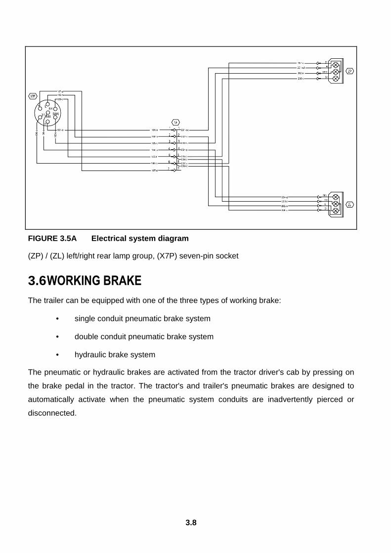
FIGURE 3.5A Electrical system diagram
(ZP) / (ZL) left/right rear lamp group, (X7P) seven-pin socket
3.6 WORKING BRAKE
The trailer can be equipped with one of the three types of working brake:
• single conduit pneumatic brake system
• double conduit pneumatic brake system
• hydraulic brake system
The pneumatic or hydraulic brakes are activated from the tractor driver's cab by pressing on
the brake pedal in the tractor. The tractor's and trailer's pneumatic brakes are designed to
automatically activate when the pneumatic system conduits are inadvertently pierced or
disconnected.
3.9
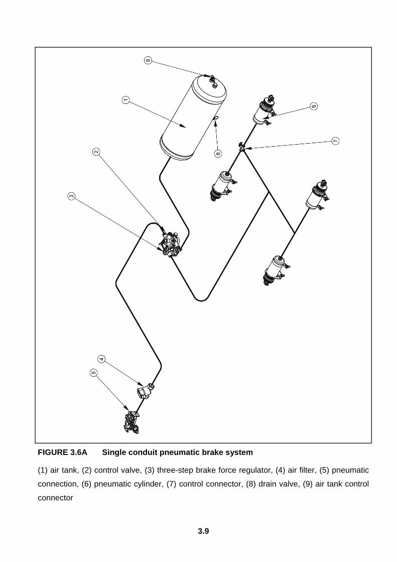
FIGURE 3.6A Single conduit pneumatic brake system
(1) air tank, (2) control valve, (3) three-step brake force regulator, (4) air filter, (5) pneumatic
connection, (6) pneumatic cylinder, (7) control connector, (8) drain valve, (9) air tank control
connector

3.10
FIGURE 3.7A Double conduit pneumatic brake system
(1) air tank, (2) control valve, (3) three-step brake force regulator, (4) air filter, (5) pneumatic
connection, (6) pneumatic cylinder, (7) control connector, (8) drain valve, (9) air tank control
connector
3.11
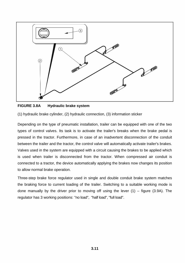
FIGURE 3.8A Hydraulic brake system
(1) hydraulic brake cylinder, (2) hydraulic connection, (3) information sticker
Depending on the type of pneumatic installation, trailer can be equipped with one of the two
types of control valves. Its task is to activate the trailer's breaks when the brake pedal is
pressed in the tractor. Furthermore, in case of an inadvertent disconnection of the conduit
between the trailer and the tractor, the control valve will automatically activate trailer's brakes.
Valves used in the system are equipped with a circuit causing the brakes to be applied which
is used when trailer is disconnected from the tractor. When compressed air conduit is
connected to a tractor, the device automatically applying the brakes now changes its position
to allow normal brake operation.
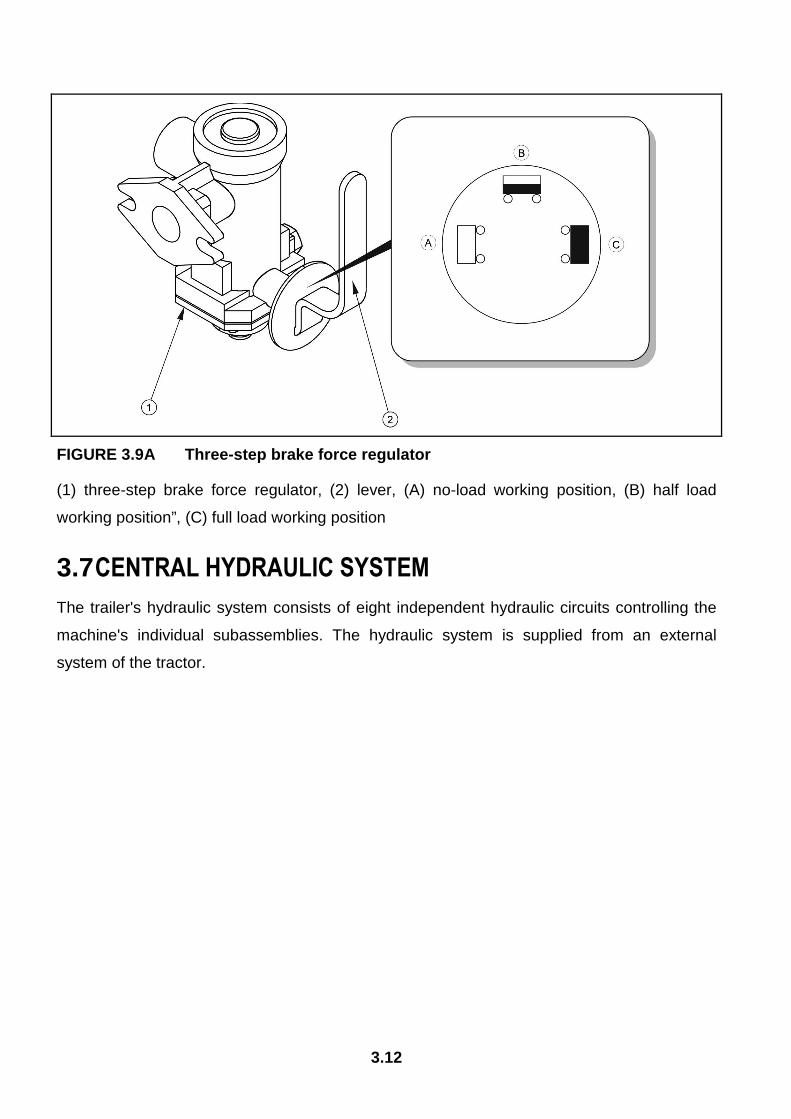
Three-step brake force regulator used in single and double conduit brake system matches
the braking force to current loading of the trailer. Switching to a suitable working mode is
done manually by the driver prior to moving off using the lever (1) – figure (3.9A). The
regulator has 3 working positions: "no load", "half load", "full load".
3.12
FIGURE 3.9A Three-step brake force regulator
(1) three-step brake force regulator, (2) lever, (A) no-load working position, (B) half load
working position”, (C) full load working position
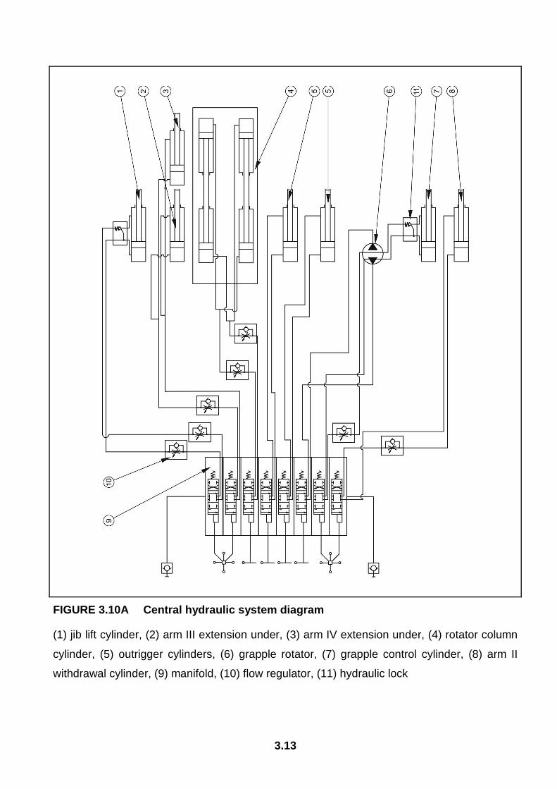
3.7 CENTRAL HYDRAULIC SYSTEM
The trailer's hydraulic system consists of eight independent hydraulic circuits controlling the
machine's individual subassemblies. The hydraulic system is supplied from an external
system of the tractor.
3.13
FIGURE 3.10A Central hydraulic system diagram
(1) jib lift cylinder, (2) arm III extension under, (3) arm IV extension under, (4) rotator column
cylinder, (5) outrigger cylinders, (6) grapple rotator, (7) grapple control cylinder, (8) arm II
withdrawal cylinder, (9) manifold, (10) flow regulator, (11) hydraulic lock
3.14
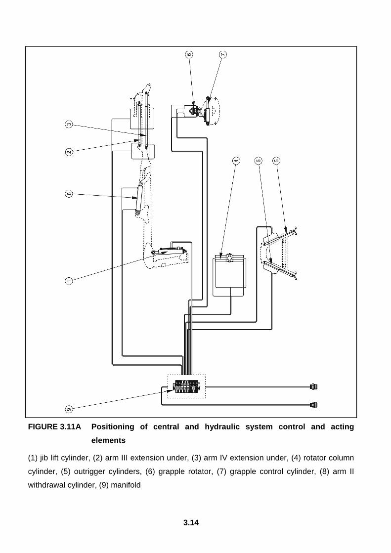
FIGURE 3.11A Positioning of central and hydraulic system control and acting
elements
(1) jib lift cylinder, (2) arm III extension under, (3) arm IV extension under, (4) rotator column
cylinder, (5) outrigger cylinders, (6) grapple rotator, (7) grapple control cylinder, (8) arm II
withdrawal cylinder, (9) manifold
3.15
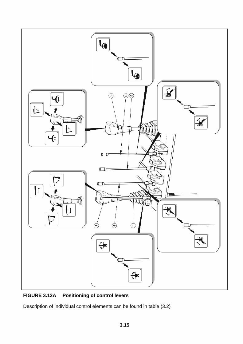
FIGURE 3.12A Positioning of control levers
Description of individual control elements can be found in table (3.2)
3.16
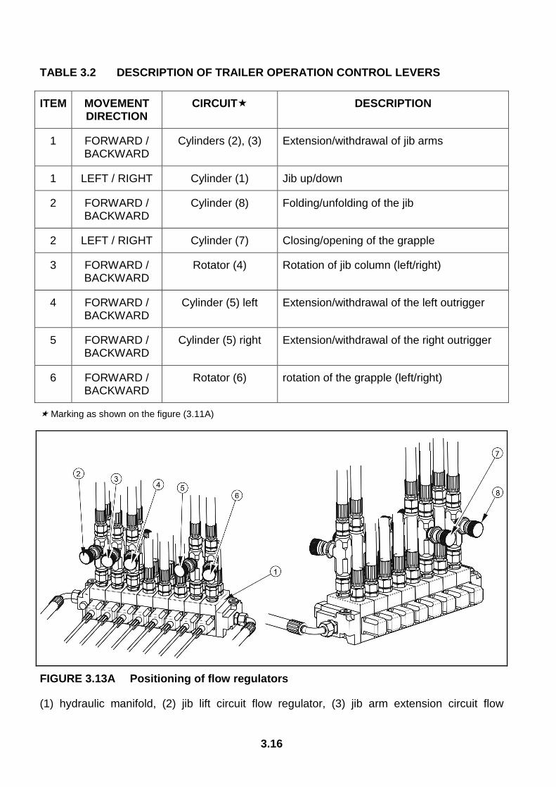
TABLE 3.2 DESCRIPTION OF TRAILER OPERATION CONTROL LEVERS
ITEM MOVEMENT DIRECTION
CIRCUIT� DESCRIPTION
1 FORWARD / BACKWARD
Cylinders (2), (3) Extension/withdrawal of jib arms
1 LEFT / RIGHT Cylinder (1) Jib up/down
2 FORWARD / BACKWARD
Cylinder (8) Folding/unfolding of the jib
2 LEFT / RIGHT Cylinder (7) Closing/opening of the grapple
3 FORWARD / BACKWARD
Rotator (4) Rotation of jib column (left/right)
4 FORWARD / BACKWARD
Cylinder (5) left Extension/withdrawal of the left outrigger
5 FORWARD / BACKWARD
Cylinder (5) right Extension/withdrawal of the right outrigger
6 FORWARD / BACKWARD
Rotator (6) rotation of the grapple (left/right)
� Marking as shown on the figure (3.11A)
FIGURE 3.13A Positioning of flow regulators
(1) hydraulic manifold, (2) jib lift circuit flow regulator, (3) jib arm extension circuit flow
3.17
regulator, (4), (7) jib rotation circuit flow regulator, (5) grapple rotation circuit flow regulator,
(6) jib folding circuit flow regulator, (8) jib lowering circuit flow regulator,
Hydraulic oil flow rate and, in turn, the speed of acting of individual cylinders, depends on the
settings of flow regulators installed in individual control circuits.
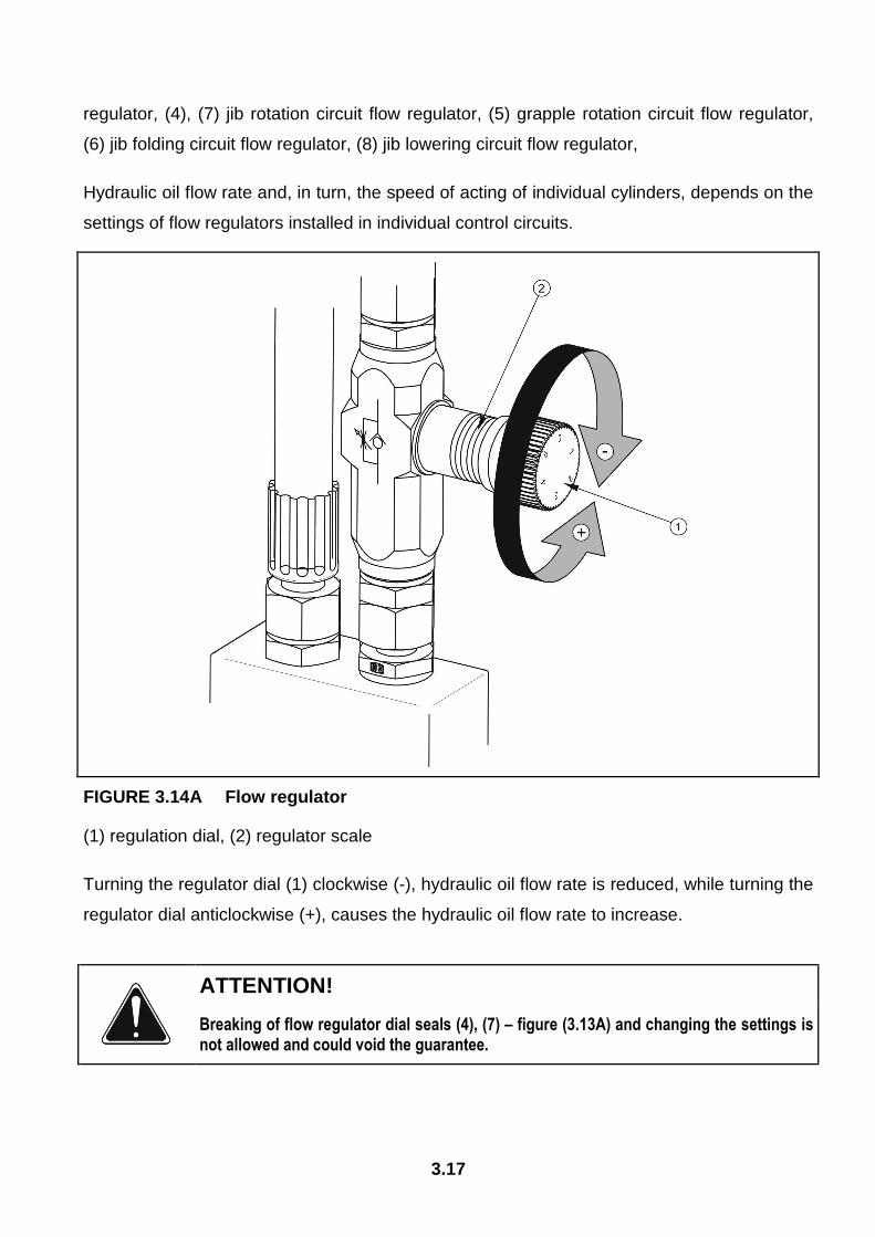
FIGURE 3.14A Flow regulator
(1) regulation dial, (2) regulator scale
Turning the regulator dial (1) clockwise (-), hydraulic oil flow rate is reduced, while turning the
regulator dial anticlockwise (+), causes the hydraulic oil flow rate to increase.
ATTENTION!
Breaking of flow regulator dial seals (4), (7) – figure (3.13A) and changing the settings is not allowed and could void the guarantee.
3.18
The Jim rotation speed to the left and the right is set in the factory -- flow regulator dials (4)
and (7) – figure (3.13A), are sealed and locked to prevent the user from changing the setting.
The time to fully rotate the grapple loader by 400° is 30 to 35 seconds.
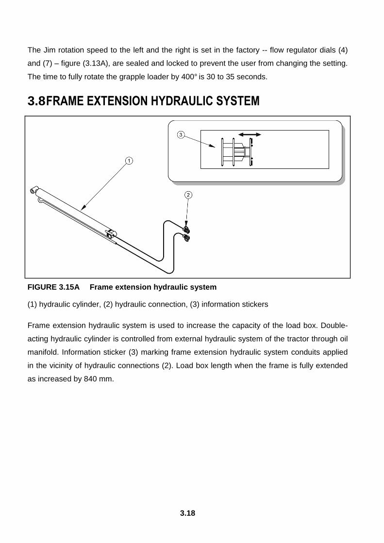
3.8 FRAME EXTENSION HYDRAULIC SYSTEM
FIGURE 3.15A Frame extension hydraulic system
(1) hydraulic cylinder, (2) hydraulic connection, (3) information stickers
Frame extension hydraulic system is used to increase the capacity of the load box. Double-
acting hydraulic cylinder is controlled from external hydraulic system of the tractor through oil
manifold. Information sticker (3) marking frame extension hydraulic system conduits applied
in the vicinity of hydraulic connections (2). Load box length when the frame is fully extended
as increased by 840 mm.
3.19
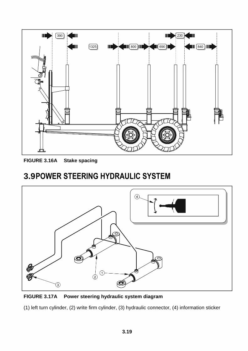
FIGURE 3.16A Stake spacing
3.9 POWER STEERING HYDRAULIC SYSTEM
FIGURE 3.17A Power steering hydraulic system diagram
(1) left turn cylinder, (2) write firm cylinder, (3) hydraulic connector, (4) information sticker

3.20
The trailer is equipped with power steering system improving steering in difficult terrain. The
power steering system must not be used when travelling on public roads. Drawbar must be
locked using the drawbar interlocking mechanism. The trailers hydraulic system is supplied
with oil from the tractor's hydraulic system. Hydraulic oil manifold of the tractor's external
hydraulic system is used to control the drawbar.
4.1
SECTION
4 CORRECT USE
PREPARING FOR WORK BEFORE FIRST USE CHECKING THE TRAILER'S TECHNICAL CONDITION ATTACHING TO TRACTOR RELOADING WORK TRANSPORTING THE TRAILER DISCONNECTING FROM TRACTOR PROPER USE AND MAINTENANCE OF TYRES
4.2
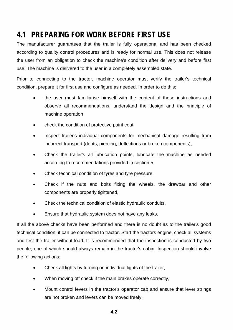
4.1 PREPARING FOR WORK BEFORE FIRST USE The manufacturer guarantees that the trailer is fully operational and has been checked
according to quality control procedures and is ready for normal use. This does not release
the user from an obligation to check the machine's condition after delivery and before first
use. The machine is delivered to the user in a completely assembled state.
Prior to connecting to the tractor, machine operator must verify the trailer's technical
condition, prepare it for first use and configure as needed. In order to do this:
• the user must familiarise himself with the content of these instructions and
observe all recommendations, understand the design and the principle of
machine operation
• check the condition of protective paint coat,
• Inspect trailer's individual components for mechanical damage resulting from
incorrect transport (dents, piercing, deflections or broken components),
• Check the trailer's all lubrication points, lubricate the machine as needed
according to recommendations provided in section 5,
• Check technical condition of tyres and tyre pressure,
• Check if the nuts and bolts fixing the wheels, the drawbar and other
components are properly tightened,
• Check the technical condition of elastic hydraulic conduits,
• Ensure that hydraulic system does not have any leaks.
If all the above checks have been performed and there is no doubt as to the trailer's good
technical condition, it can be connected to tractor. Start the tractors engine, check all systems
and test the trailer without load. It is recommended that the inspection is conducted by two
people, one of which should always remain in the tractor's cabin. Inspection should involve
the following actions:
• Check all lights by turning on individual lights of the trailer,
• When moving off check if the main brakes operate correctly,
• Mount control levers in the tractor's operator cab and ensure that lever strings
are not broken and levers can be moved freely,
4.3
• Check of the hydraulic system operates correctly by activating individual
hydraulic cylinders (first extend hydraulic cylinders of the left and right outrigger
prior to activating any other components),
• Ensure that hydraulic system does not have any leaks.
ATTENTION!
The trailer must not be used for purposes other than those for which it is intended. Trailer's technical condition must be verified before each use and especially the hitch system, axle system, brakes, hydraulic system, lights and if all safety guards are in place.
The technical condition of the trailer's main brake can only be checked after removing off.
Ensure that brake force regulator is in NO LOAD serving .
DANGER:
Before using the trailer, the user must thoroughly familiarise himself with the content of these instructions. Careless and improper use and operation of the trailer, and non-adherence to the recommendations included in these instructions are dangerous for the health. The trailer must never be used by persons who are not authorised to drive agricultural tractors, including children and people under the influence of alcohol or other drugs. Non-adherence to the principles of safe use creates a danger for the health and life of the operator and others.
If any faults are detected they must be identified and rectified. If a fault cannot be rectified or
the repair could void the guarantee, please contact retailer for additional clarifications.
4.2 CHECKING THE TRAILER'S TECHNICAL CONDITION When preparing the trailer for normal use, check individual elements according to guidelines
presented in table (4.1).

4.4
TABLE 4.1 TECHNICAL INSPECTION SCHEDULE
DESCRIPTION SERVICE OPERATION FREQUENCY
Condition of safeguards check the technical condition of safeguards, if complete and correctly mounted.
Operation of main brakes Attach trailer to the tractor and test the brakes after moving off.
Correct operation of lights and indicators.
After connecting trailer to the tractor activate in sequence individual lights, check if all reflective lights are installed, check if slow-moving vehicle warning sign is in place.
Technical condition of the hydraulic system.
Check tightness of hydraulic system, inspect cylinders and hydraulic conduits.
Check technical condition of tyres and tyre pressure,
Visually inspect the tyres and if they are properly inflated.
Bef
ore
each
use
Check technical condition of tyres and tyre pressure,
Check the condition of tyre tread, lateral surfaces, wheel rim and if necessary inflate the tyres up to recommend pressure
Technical condition of the brake system.
Inspect all individual elements of the system, check the conduits for wear and tear, check connector sealing, drain water from the air tank (for pneumatic brake system), when connected to tractor, move off and apply brakes to verify that they work properly and braking is uniform.
Technical condition of the hydraulic system.
Carefully inspect the system, check sealing of hydraulic cylinders, check hydraulic conduits for damage and wear and tear, check all connections.
Eve
ry m
onth
Check of all main nut and bolt connections are properly tightened
Torque values should be according to table (5.5).
Eve
ry s
ix
mon
ths
Lubrication Lubricate elements according to guidelines presented in section "lubrication points".
Acc
ordi
ng to
ta
ble
(5.4
)
4.5
ATTENTION!
The trailer must not be used when not in working order. Prior to commencing hydraulic system conduits the user must familiarise himself with the content of the tractors operating instructions and observe all recommendations of the manufacturer.
4.3 ATTACHING TO TRACTOR Linkage of the trailer and the tractor is only possible when tractor is equipped with a hitch
with permissible vertical load off more than 2,000 kg.
In order to attach the trailer to tractor, perform the following:
• While tractor is in reverse, connect drawbar eye to the tractor's hitch and check
if the connection is secure,
• raise the parking stand,
• prevent parking stand from falling using a pin,
• connect electrical leads to the tractor as well as hydraulic and braking system
conduits,
• install control support in the tractor's cab,
• Place a slow-moving vehicle warning sign in extendable frame.
DANGER
When attaching, there must be nobody between the trailer and the tractor. when attaching the machine, tractors driver must exercise caution and make sure that no body is present in the hazard zone. Be especially careful when attaching the machine. When connecting the hydraulic conduits to the tractor, make sure that the hydraulic systems of the tractor and trailer are not under pressure.
Hydraulic system conduits are marked by stickers (17), (18) and (19) - table (2.1). The only
exception are central hydraulic system conduits which are not marked.
4.6
When connecting braking system conduits (this refers to double-conduit pneumatic system),
first connect the yellow connector to yellow socket in the tractor and only then connect the
red connector to the red socket in the tractor. Once the 2nd conduit connected, the braking
system will switch to normal mode of operation (disconnection or piercing of the conduits
causes the trailer's braking system control valve to automatically apply brakes). Prior to
moving off, set the brake force regulator to a suitable setting (depending on the load carried
in the load box).
ATTENTION!
Prior to attaching the trailer, check the technical condition of the trailer's and tractor's hitch system and connection elements of the hydraulic, electrical and pneumatic systems.
Trailer's conduit connectors and the tractor's connection sockets must be free from any
contamination. Pneumatic system conduit connectors are equipped with rubber seals which
must not be damaged or soiled.
ATTENTION!
The trailer must not be moved when the parking stand is extended and rests on the ground. If moved there is a risk of damage to the parking stand. Trailer may be attached exclusively to a tractor which meets the requirements for a minimum power demand, is equipped with suitable braking and hydraulic systems connection sockets, hydraulic oil in both machines is of the same type and the tractor's hitch is capable of withstanding vertical loads of loaded trailer drawbar. When attaching is completed, secure the electrical leads and hydraulic and braking system conduits in such a way that they do not become entangled in tractor's moving parts and are not at the risk of breaking or piercing when making turns.
4.4 RELOADING WORK Load box can be loaded only when the trailer is connected to the tractor and positioned
horizontally. Always aim at distributing the load uniformly in the load box. This will ensure
stability when travelling and correct axle and drawbar loads.
4.7
DANGER
The maximum carrying capacity of the trailer and the grapple loader lift must not be exceeded. People or animals must not be carried. Loading and unloading work should be carried out by someone experienced in this type of work. The load may not protrude further out than the upper edge of the trailer's front wall. Prior to loading or unloading work trailer's outrigger supports must be extended outrigger supports and the tractor's parking brake must be engaged. Load must be uniformly distributed and it must not obstruct visibility or hinder driving.
Before starting the loading or unloading work remove the slow-moving vehicle warning sign
and extend both left and right of outrigger supports in order to ensure trailer stability. When
trailer is used in difficult terrain it is allowable in extreme cases to load the trailer on a slope
which is not steeper than 5°. In this case the jib may only be directed on the side which is
higher. Turning the jib to the lower side poses substantial risk for the trailer's stability and is
hazardous.
4.8
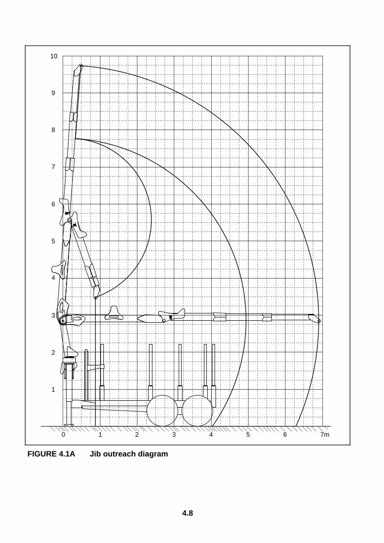
FIGURE 4.1A Jib outreach diagram
0 1 2 3 4 5 6 7m
1
2
3
4
5
6
7
8
9
10
4.9
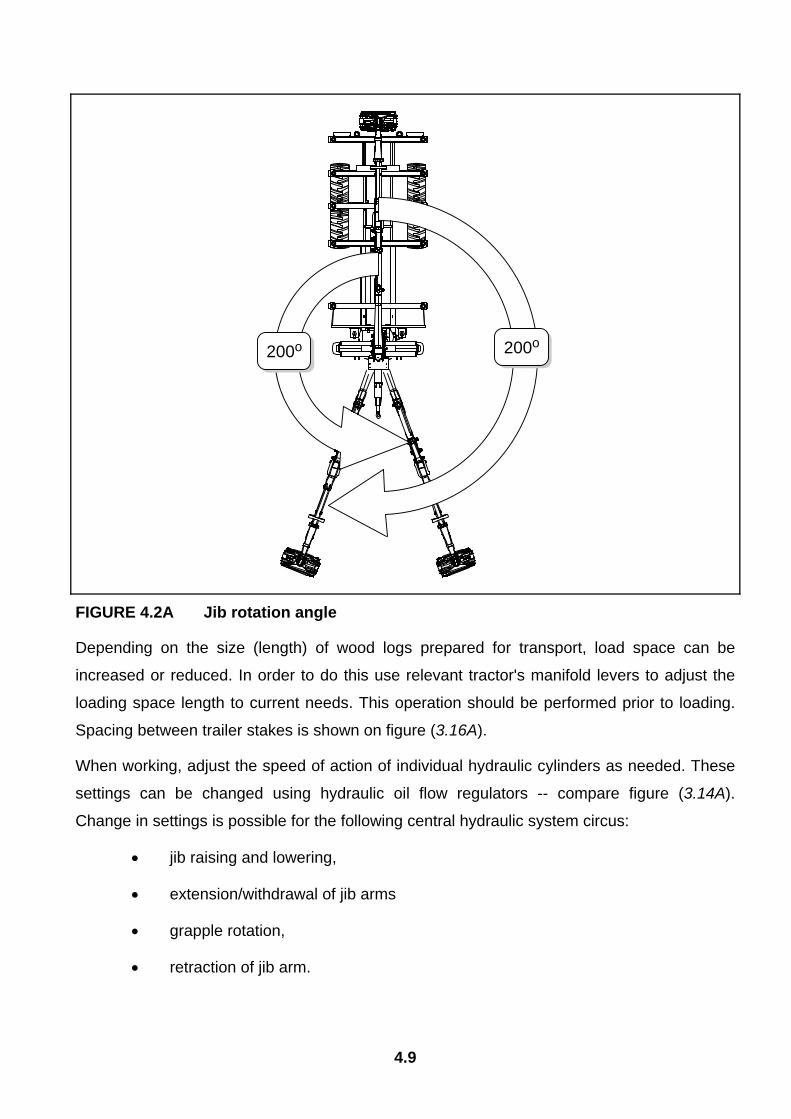
FIGURE 4.2A Jib rotation angle
Depending on the size (length) of wood logs prepared for transport, load space can be
increased or reduced. In order to do this use relevant tractor's manifold levers to adjust the
loading space length to current needs. This operation should be performed prior to loading.
Spacing between trailer stakes is shown on figure (3.16A).
When working, adjust the speed of action of individual hydraulic cylinders as needed. These
settings can be changed using hydraulic oil flow regulators -- compare figure (3.14A).
Change in settings is possible for the following central hydraulic system circus:
• jib raising and lowering,
• extension/withdrawal of jib arms
• grapple rotation,
• retraction of jib arm.
200o200o

4.10
All hydraulic oil flow regulators of the jib rotation circuit have factory settings and are lead-
sealed. Any attempt to change the setting in this circuit may damage the trailer and void the
guarantee.
4.5 TRANSPORTING THE TRAILER When travelling on public roads, respect the road traffic regulations, exercise caution and
prudence. Listed below are the key guidelines for driving the tractor and trailer combination.
• Before moving off make sure that there are no bystanders, especially children, near the
trailer or the tractor. Take care that the driver has sufficient visibility.
• Make sure that the trailer is correctly attached to the tractor and tractor's hitch is properly
secured.
• The trailer must not be overloaded, loads must be uniformly distributed so that the
maximum permissible axle and drawbar loads are not exceeded. The trailer's maximum
carrying capacity must not be exceeded as this can cause damage the machine and pose
a risk for the operator or other road users.
• Permissible design speed and maximum speed allowable by road traffic law must not be
exceeded. The towing speed should be adapted to the current road conditions, load
carried by the trailer, road surface conditions and other relevant conditions.
• In the event of trailer malfunction, pull over on the hard shoulder avoiding any risk to
other road users and position reflective warning triangle according to traffic regulations.
• While driving on public roads the trailer must be fitted with a certified or authorised
reflective warning triangle. When driving, comply with all road traffic regulations, indicate
an intention to turn using indicator lamps, keep all road lights and indicator lights clean at
all times and ensure they are in good condition. Any damaged or lost lamps or indicator
lights must be immediately repaired or replaced.
• Avoid ruts, depressions, indigenous or driving on road side slopes. Driving across such
obstacles could cause the trailer or the tractor to suddenly tilt. This is of special
importance because loaded trailer's centre of gravity is higher, which reduces safety.
Driving near ditches or channels is dangerous as there is a risk of the wheels sliding
down the slope or the slope collapsing.
4.11
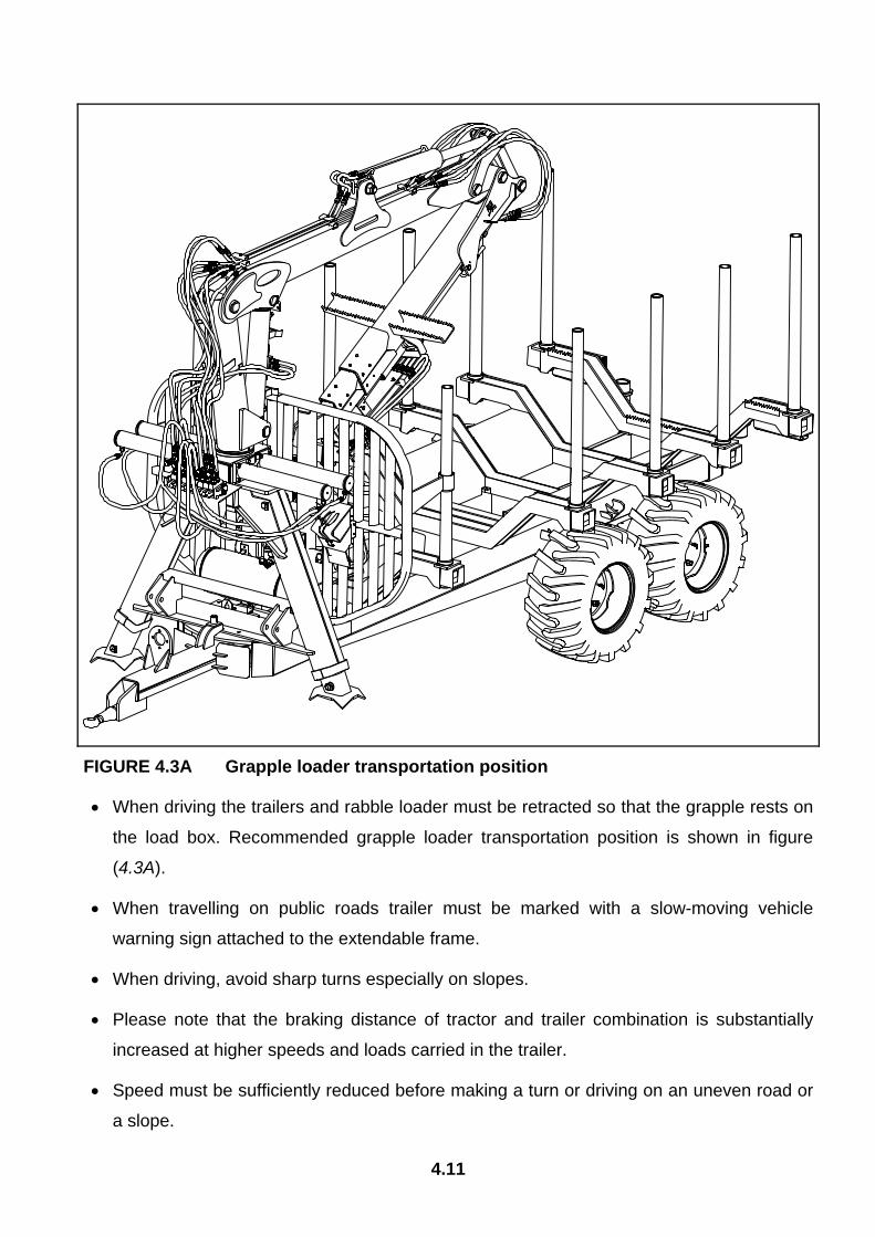
FIGURE 4.3A Grapple loader transportation position
• When driving the trailers and rabble loader must be retracted so that the grapple rests on
the load box. Recommended grapple loader transportation position is shown in figure
(4.3A).
• When travelling on public roads trailer must be marked with a slow-moving vehicle
warning sign attached to the extendable frame.
• When driving, avoid sharp turns especially on slopes.
• Please note that the braking distance of tractor and trailer combination is substantially
increased at higher speeds and loads carried in the trailer.
• Speed must be sufficiently reduced before making a turn or driving on an uneven road or
a slope.
4.12
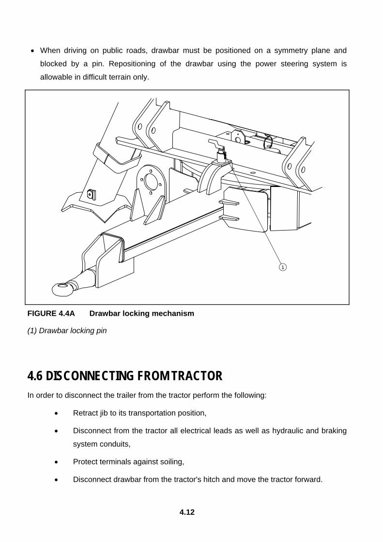
• When driving on public roads, drawbar must be positioned on a symmetry plane and
blocked by a pin. Repositioning of the drawbar using the power steering system is
allowable in difficult terrain only.
FIGURE 4.4A Drawbar locking mechanism
(1) Drawbar locking pin
4.6 DISCONNECTING FROM TRACTOR In order to disconnect the trailer from the tractor perform the following:
• Retract jib to its transportation position,
• Disconnect from the tractor all electrical leads as well as hydraulic and braking
system conduits,
• Protect terminals against soiling,
• Disconnect drawbar from the tractor's hitch and move the tractor forward.
1

4.13
DANGER
When disconnecting the trailer maintain safe distance from the drawbar, which can suddenly move upwards. Trailer must not be disconnected when grapple loader jib is raised. Jib must be retracted to its transportation position, Trailer must not be disconnected when loaded.
When disconnecting pneumatic system conduits (this refers to double-conduit pneumatic
system), first disconnect the red connector and only then disconnect the yellow connector.
4.7 PROPER USE AND MAINTENANCE OF TYRES • When working on the tyres, wedges or other objects without sharp edges
should be placed under the wheels of the trailer to prevent it from rolling. The
wheel can be taken off only when the trailer is not loaded.
• Repair work on the wheels or tyres should be carried out by persons trained
and entitled to do so. This work should be carried out using appropriately
selected tools.
• After removing a wheel, always check how firmly the nuts are screwed in.
Individual checks should be made after the first use, after the first journey with a
load, after travelling 1000 km and then every 6 months. The above actions
should be repeated individually if a wheel has been removed from the wheel
axle.
• Regularly check and maintain correct pressure in tyres according to instructions
(especially if trailer is not used for a longer period).
• Pressure and tyres should be also checked after the whole day of intensive
work. Please note that higher temperatures could raise tire pressure by as
much as 1 bar. At high temperatures and pressure reduced load or speed.
• Do not release air from warm tyres to adjust the pressure or the tyres will be
underinflated when temperatures return to normal.
• Protect valves using suitable caps to avoid soiling.
• Do not exceed the trailer's maximum design speed.

4.14
• When trailer is operated all day, stop working for a minimum of one hour in the
afternoon.
• Avoid potholes, sudden manoeuvres or high speeds when turning.
5.1
SECTION
5 TECHNICAL MAINTENANCE
INSPECTION OF WHEEL AXLE BEARINGS REGULATION OF MAIN BRAKES REGULATION OF ROCKER ARM BEARING PNEUMATIC SYSTEM OPERATION HYDRAULIC SYSTEM OPERATION STORAGE LUBRICATION TIGHTENING TORQUE FOR NUT AND BOLT CONNECTIONS FAULTS AND MEANS OF REMEDYING THEM LIST OF BULBS
5.2
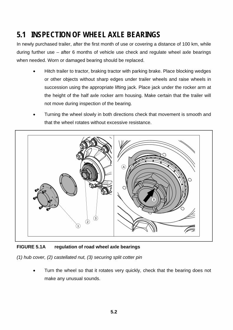
5.1 INSPECTION OF WHEEL AXLE BEARINGS In newly purchased trailer, after the first month of use or covering a distance of 100 km, while
during further use – after 6 months of vehicle use check and regulate wheel axle bearings
when needed. Worn or damaged bearing should be replaced.
• Hitch trailer to tractor, braking tractor with parking brake. Place blocking wedges
or other objects without sharp edges under trailer wheels and raise wheels in
succession using the appropriate lifting jack. Place jack under the rocker arm at
the height of the half axle rocker arm housing. Make certain that the trailer will
not move during inspection of the bearing.
• Turning the wheel slowly in both directions check that movement is smooth and
that the wheel rotates without excessive resistance.
FIGURE 5.1A regulation of road wheel axle bearings
(1) hub cover, (2) castellated nut, (3) securing split cotter pin
• Turn the wheel so that it rotates very quickly, check that the bearing does not
make any unusual sounds.
A
B
12
3
5.3
• Grasp wheel above and below and try to feel any slack play, this may equally
be checked with the aid of a jack placed under the wheel supported on the
floor/ground.
If slack is felt, it is necessary to adjust bearing. Unusual sounds coming from bearing may be
symptoms of excess wear, dirt or damage. In such an event the bearing, together with
sealing ring, should be replaced with new parts.
Bearing regulation should be performed according to the following instructions – figure
(5.1A):
• take off hub cover (1),
• take out split cotter pin (3) securing castellated nut (2),
• turning the wheel simultaneously tighten castellated nut until the wheel comes
to a stop,
• unscrew nut (not less than1/3 rotation) to cover the nearest thread groove with
alignment to opening in wheel stub axle
• secure castellated nut was cotter pin and mount hub cap.
The wheel should turn smoothly without faltering or detectable resistance not originating from
abrasion of brake shoes in brake drum.
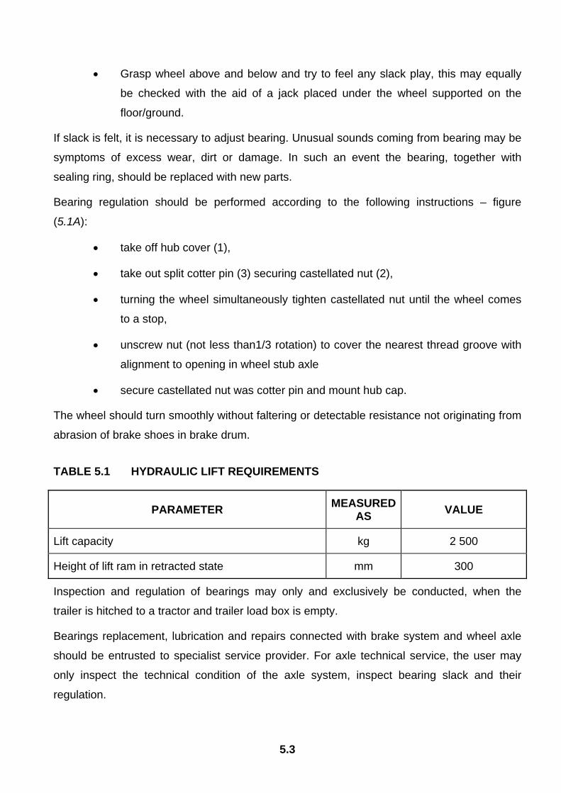
TABLE 5.1 HYDRAULIC LIFT REQUIREMENTS
PARAMETER MEASURED AS VALUE
Lift capacity kg 2 500
Height of lift ram in retracted state mm 300
Inspection and regulation of bearings may only and exclusively be conducted, when the
trailer is hitched to a tractor and trailer load box is empty.
Bearings replacement, lubrication and repairs connected with brake system and wheel axle
should be entrusted to specialist service provider. For axle technical service, the user may
only inspect the technical condition of the axle system, inspect bearing slack and their
regulation.
5.4
Inspection of slack and technical condition of wheel axle bearings must be performed after the first month of use or 100km of travel, and then every 6 months of trailer use.
5.2 REGULATION OF MAIN BRAKES Brakes regulation is necessary when:
• as a result of wear of brake shoe linings between lining and drum there is
excessive slack and reduced braking effectiveness.
• wheel brakes do not brake evenly or simultaneously.
If brakes are correctly regulated, braking of trailer road wheel takes place simultaneously.
Brakes regulation consists of changing setting of axle shaft expander arm (2) in relation to
expander shafts (1). To do this, dismantle axle shaft arm and set it in the correct direction i.e.:
• in direction A, if braking is too early,
• in direction B, if breaking is too late.
Regulation should be conducted separately for each wheel. After proper brake regulation, at
full braking the axle shaft expander arm should create an angle of 90° with ram piston. Axle
shaft expander arms must make the same movement and braking process must take place
simultaneously on all wheels. After brake release expander arms may not be supported on
any construction elements, because too little withdrawal of a piston ram may cause abrasion
of brake shoes in drum and result in overheating trailer brakes.
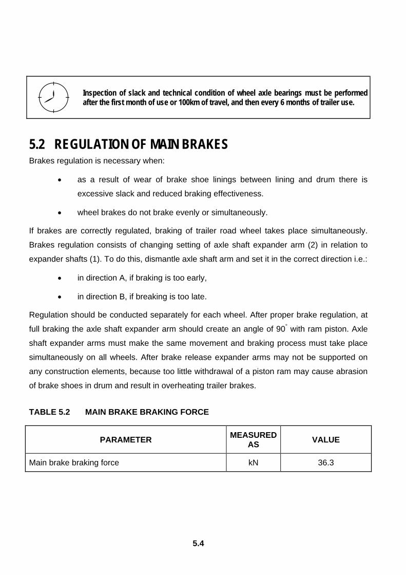
TABLE 5.2 MAIN BRAKE BRAKING FORCE
PARAMETER MEASURED AS VALUE
Main brake braking force kN 36.3
5.5
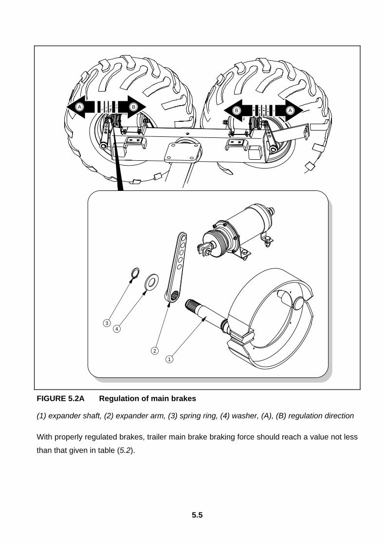
FIGURE 5.2A Regulation of main brakes
(1) expander shaft, (2) expander arm, (3) spring ring, (4) washer, (A), (B) regulation direction
With properly regulated brakes, trailer main brake braking force should reach a value not less
than that given in table (5.2).
12
43
A BB A
5.6
The main brake system should be inspected annually and in case of need should be regulated.
Difference in braking force of left and right wheel may not be greater than 30%, considering
that 100% constitutes greater force.
IMPORTANT!
Main brake braking force, is the braking force of all trailer wheels.
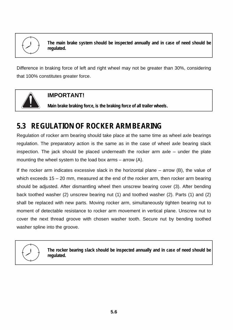
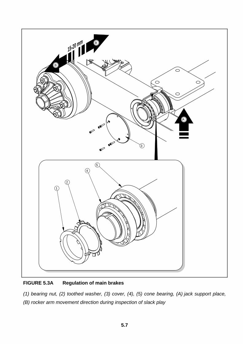
5.3 REGULATION OF ROCKER ARM BEARING Regulation of rocker arm bearing should take place at the same time as wheel axle bearings
regulation. The preparatory action is the same as in the case of wheel axle bearing slack
inspection. The jack should be placed underneath the rocker arm axle – under the plate
mounting the wheel system to the load box arms – arrow (A).
If the rocker arm indicates excessive slack in the horizontal plane – arrow (B), the value of
which exceeds 15 – 20 mm, measured at the end of the rocker arm, then rocker arm bearing
should be adjusted. After dismantling wheel then unscrew bearing cover (3). After bending
back toothed washer (2) unscrew bearing nut (1) and toothed washer (2). Parts (1) and (2)
shall be replaced with new parts. Moving rocker arm, simultaneously tighten bearing nut to
moment of detectable resistance to rocker arm movement in vertical plane. Unscrew nut to
cover the next thread groove with chosen washer tooth. Secure nut by bending toothed
washer spline into the groove.
The rocker bearing slack should be inspected annually and in case of need should be regulated.
5.7
FIGURE 5.3A Regulation of main brakes
(1) bearing nut, (2) toothed washer, (3) cover, (4), (5) cone bearing, (A) jack support place,
(B) rocker arm movement direction during inspection of slack play
1
2
3
4
5
A
m15-20 m
B
B

5.8
DANGER:
The trailer must not be supported with the aid of brittle crumbling elements, e.g. hollow blocks, bricks or concrete blocks. The trailer should be prevented from rolling using wedges placed both sides under the wheels. After raising the trailer an additional strong solid support should be placed.
5.4 PNEUMATIC SYSTEM OPERATION As a part of trailer maintenance, it is necessary to conduct inspection of individual pneumatic
systems, giving particular attention to places of all connections. Tightness of the system
should be checked at nominal pressure in system of approximately 600 kPa (6.0 kg/cm2).
If conduits, seals or other system elements are damaged, compressed air will escape in
these damaged places with a characteristic hiss. Lack of system tightness may be exposed
by covering checked elements with washing fluid or other foaming preparations, which will
not react aggressively with system elements. Damaged seals or conduits, causing leaks
should be replaced. If the cause of the system leak is the outflow from a piston, control valve
body or braking force regulator should be taken to authorised repair provider for repair or
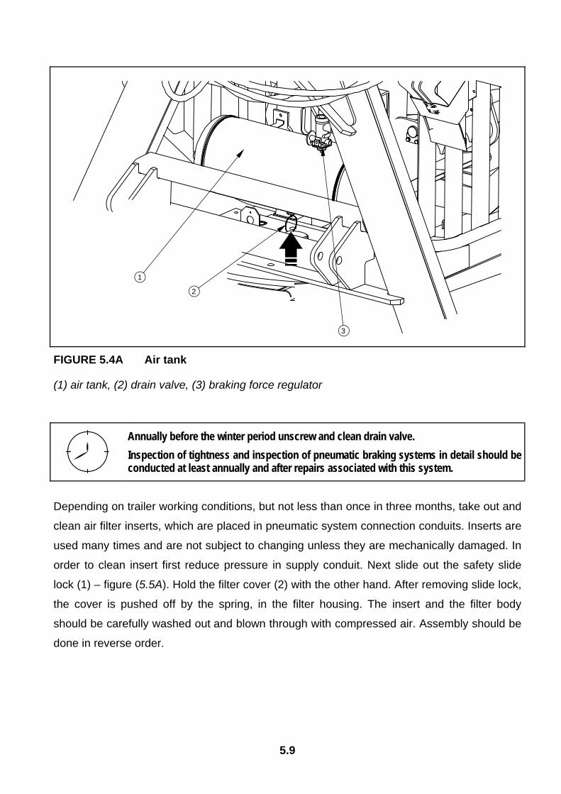
replacement of parts. At least once a month condensation collecting as water should be
removed from air tank. In order to do this open out drain valve (2) placed in lower part of
tank - figure (5.4A). The compressed air in the tank causes the removal of water to the
exterior. After release valve mandrel should automatically close and stop air flow from tank.
Annually before the winter period unscrew drain valve and clean off accumulated dirt.
Replace copper seal.
Contact of pneumatic leads with oils, greases, petrol etc. may cause damage and accelerate
ageing process. Bent conduits, permanently deformed, cut or worn should be replaced.
5.9
FIGURE 5.4A Air tank
(1) air tank, (2) drain valve, (3) braking force regulator
Annually before the winter period unscrew and clean drain valve. Inspection of tightness and inspection of pneumatic braking systems in detail should be conducted at least annually and after repairs associated with this system.
Depending on trailer working conditions, but not less than once in three months, take out and
clean air filter inserts, which are placed in pneumatic system connection conduits. Inserts are
used many times and are not subject to changing unless they are mechanically damaged. In
order to clean insert first reduce pressure in supply conduit. Next slide out the safety slide
lock (1) – figure (5.5A). Hold the filter cover (2) with the other hand. After removing slide lock,
the cover is pushed off by the spring, in the filter housing. The insert and the filter body
should be carefully washed out and blown through with compressed air. Assembly should be
done in reverse order.
2
1
3

5.10
The insert and the air filter body should be cleaned at least every 3 months of trailer use.
FIGURE 5.5A Air filter
(1) securing slide lock, (2) air filter cover
DANGER:
Before proceeding to dismantle filter, reduce pressure in supply conduit. While disengaging filter slide lock, hold cover with other hand. Stand away from filter cover vertical direction.
Pneumatic system connection must be inspected on regularly during use of trailer and if
necessary cleaned of all contamination. Particular attention should be paid to the technical
condition of security covers and rubber seals. If these elements are damaged they should be
replaced. It is recommended that seals are preserved with silicon preparation, specified for
rubber elements every six months. Contact of the seals with fuel, lubricants being petroleum
derivatives, paints etc., causes rapid ageing of the material from which they are made.
1
2
5.11
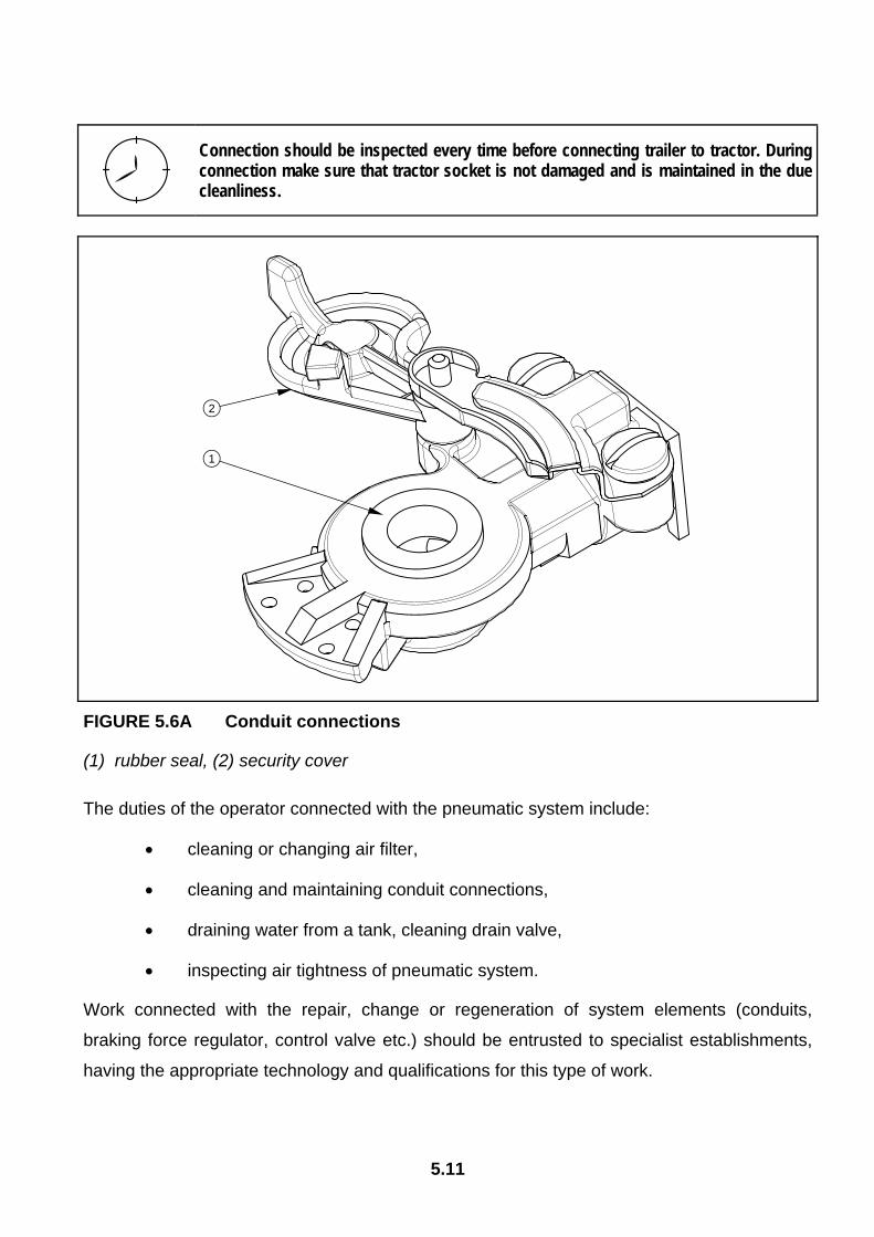
Connection should be inspected every time before connecting trailer to tractor. During connection make sure that tractor socket is not damaged and is maintained in the due cleanliness.
FIGURE 5.6A Conduit connections
(1) rubber seal, (2) security cover
The duties of the operator connected with the pneumatic system include:
• cleaning or changing air filter,
• cleaning and maintaining conduit connections,
• draining water from a tank, cleaning drain valve,
• inspecting air tightness of pneumatic system.
Work connected with the repair, change or regeneration of system elements (conduits,
braking force regulator, control valve etc.) should be entrusted to specialist establishments,
having the appropriate technology and qualifications for this type of work.
1
2
5.12
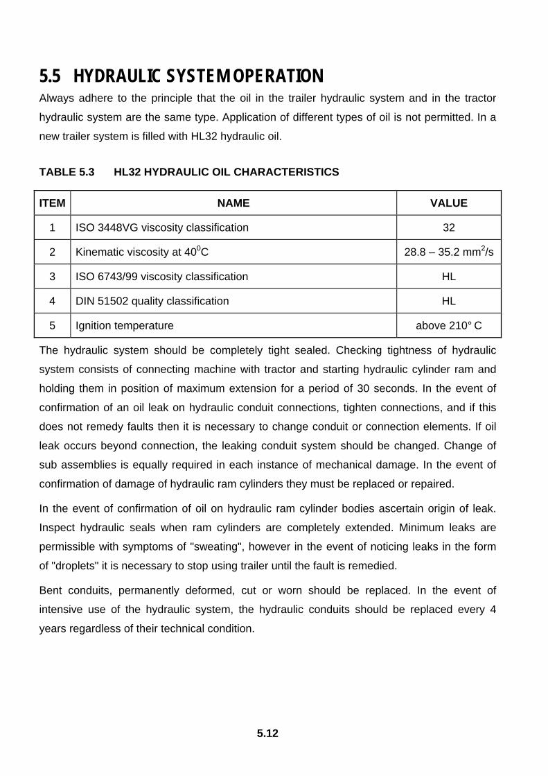
5.5 HYDRAULIC SYSTEM OPERATION Always adhere to the principle that the oil in the trailer hydraulic system and in the tractor
hydraulic system are the same type. Application of different types of oil is not permitted. In a
new trailer system is filled with HL32 hydraulic oil.
TABLE 5.3 HL32 HYDRAULIC OIL CHARACTERISTICS
ITEM NAME VALUE
1 ISO 3448VG viscosity classification 32
2 Kinematic viscosity at 400C 28.8 – 35.2 mm2/s
3 ISO 6743/99 viscosity classification HL
4 DIN 51502 quality classification HL
5 Ignition temperature above 210° C
The hydraulic system should be completely tight sealed. Checking tightness of hydraulic
system consists of connecting machine with tractor and starting hydraulic cylinder ram and
holding them in position of maximum extension for a period of 30 seconds. In the event of
confirmation of an oil leak on hydraulic conduit connections, tighten connections, and if this
does not remedy faults then it is necessary to change conduit or connection elements. If oil
leak occurs beyond connection, the leaking conduit system should be changed. Change of
sub assemblies is equally required in each instance of mechanical damage. In the event of
confirmation of damage of hydraulic ram cylinders they must be replaced or repaired.
In the event of confirmation of oil on hydraulic ram cylinder bodies ascertain origin of leak.
Inspect hydraulic seals when ram cylinders are completely extended. Minimum leaks are
permissible with symptoms of "sweating", however in the event of noticing leaks in the form
of "droplets" it is necessary to stop using trailer until the fault is remedied.
Bent conduits, permanently deformed, cut or worn should be replaced. In the event of
intensive use of the hydraulic system, the hydraulic conduits should be replaced every 4
years regardless of their technical condition.
5.13
IMPORTANT!
Trailer with a leaking hydraulic system must NOT be used. The condition of hydraulic systems should be inspected regularly while using trailer. The hydraulic system is under high pressure when operating. Regularly check the technical condition of the connections and the hydraulic conduits. Use the hydraulic oil recommended by the Producer. Never mix two types of oil.
In the event of necessity of changing hydraulic oil for another oil, check the recommendations
of the oil producer very carefully. If it is recommended to flush the system with the
appropriate preparation, then it is necessary to comply with these recommendations.
Attention should be given, so that chemical substances used for this purpose do not damage
the materials of the hydraulic system.
The oil applied because of its composition is not classified as a dangerous substance,
however long-term action on the skin or eyes may cause irritation. In the event of contact of
oil with skin wash the place of contact with water and soap. Do not apply organic solvents
(petrol, kerosene). Contaminated clothing should be changed to prevent access of oil to skin.
In the event of contact of oil with eye, rinse with large quantity of water and in the event of the
occurrence of irritation consultant a doctor. Hydraulic oil in normal conditions is not harmful to
the respiratory tract. A hazard only occurs when oil is strongly atomised (oil vapour), or in the
case of fire during which toxic compounds may be released. Oil fires should be quenched
with the use of carbon dioxide, foam or extinguisher steam. Do not use water to quench oil
fires.
Hydraulic conduits should be replaced after 4 years of trailer use. Detailed tightness and technical condition inspection of hydraulic system should be made at least annually.
The duties of the operator connected with the pneumatic system include:
• inspect tightness of hydraulic connections,
• inspect technical condition of conduits,
5.14
Work connected with the repair, change or regeneration of system elements (hydraulic ram
cylinders, conduit connections, hydraulic manifold, flow regulators etc.) should be entrusted
to specialist establishments, having the appropriate technology and qualifications for this type
of work.
5.6 STORAGE After finishing work with trailer cleaned thoroughly and wash with water jet. In the event of
damage to the paint coat, clean rust and dust from damaged area, degrease and then paint
with undercoat and after it is dry paint with surface coat paint retaining colour uniformity and
even thickness of protective coating. Until the time of repainting the damaged place may be
covered with a thin layer of grease or anticorrosion preparation. Trailer should be kept in
closed or roofed building temperature above 0oC.
If the trailer will not be used for a long time, it is essential to protect it from adverse weather,
especially rust and accelerated tyre deterioration. During this time trailer must be unloaded.
Trailer should be very carefully washed and dried. While washing do not direct a strong water
or steam jet at information and warning stickers, electrical equipment elements, and hydraulic
and pneumatic systems. Nozzle of pressure or steam washer should be kept at a distance of
not less than 30 cm from cleaned surface. Corroded areas should be protected as described
above.
Trailer should be lubricated according to instructions provided. In the event of prolonged work
stoppage, it is essential to lubricate all elements regardless of the period of the last
lubrication process.
Tyres should undergo conservation maintenance at least twice a year using the appropriate
preparations designed for this purpose. Wheels and tyres should be previously carefully
washed and dried. During longer storage of unused trailer it is recommended that every 2 to
3 weeks the trailer may be moved a bit so that the place of contact of tyres with ground is
changed. So that tyres are not deformed and maintain proper geometry. Also tyre pressure
should be inspected from time to time, and if necessary pressure should be increased to
appropriate value.
During trailer storage, jib should be placed in transport position.
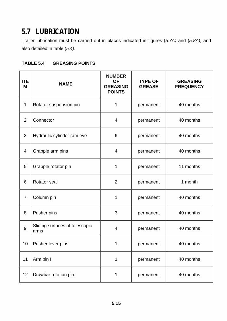
5.15
5.7 LUBRICATION Trailer lubrication must be carried out in places indicated in figures (5.7A) and (5.8A), and
also detailed in table (5.4).
TABLE 5.4 GREASING POINTS
ITEM NAME
NUMBER OF
GREASING POINTS
TYPE OF GREASE
GREASING FREQUENCY
1 Rotator suspension pin 1 permanent 40 months
2 Connector 4 permanent 40 months
3 Hydraulic cylinder ram eye 6 permanent 40 months
4 Grapple arm pins 4 permanent 40 months
5 Grapple rotator pin 1 permanent 11 months
6 Rotator seal 2 permanent 1 month
7 Column pin 1 permanent 40 months
8 Pusher pins 3 permanent 40 months
9 Sliding surfaces of telescopic arms 4 permanent 40 months
10 Pusher lever pins 1 permanent 40 months
11 Arm pin I 1 permanent 40 months
12 Drawbar rotation pin 1 permanent 40 months
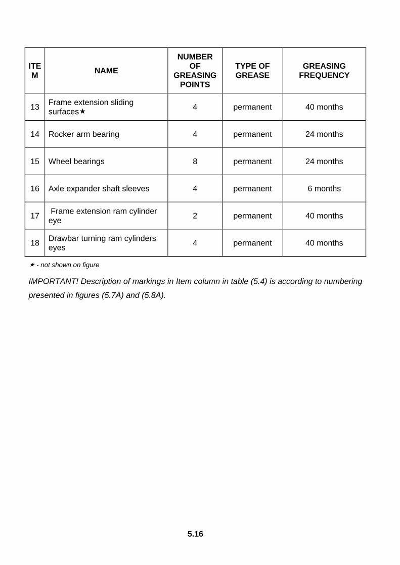
5.16
ITEM NAME
NUMBER OF
GREASING POINTS
TYPE OF GREASE
GREASING FREQUENCY
13 Frame extension sliding surfaces 4 permanent 40 months
14 Rocker arm bearing 4 permanent 24 months
15 Wheel bearings 8 permanent 24 months
16 Axle expander shaft sleeves 4 permanent 6 months
17 Frame extension ram cylinder eye 2 permanent 40 months
18 Drawbar turning ram cylinders eyes 4 permanent 40 months
- not shown on figure
IMPORTANT! Description of markings in Item column in table (5.4) is according to numbering
presented in figures (5.7A) and (5.8A).
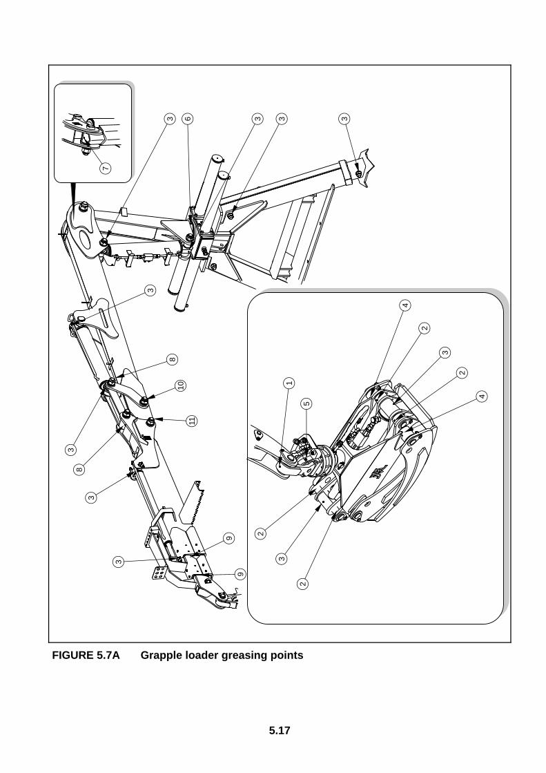
5.17
FIGURE 5.7A Grapple loader greasing points
1
2
2
2
2
3
3
4
4
5
6 3 333
3
3
3
3
7
8
8
99
1011
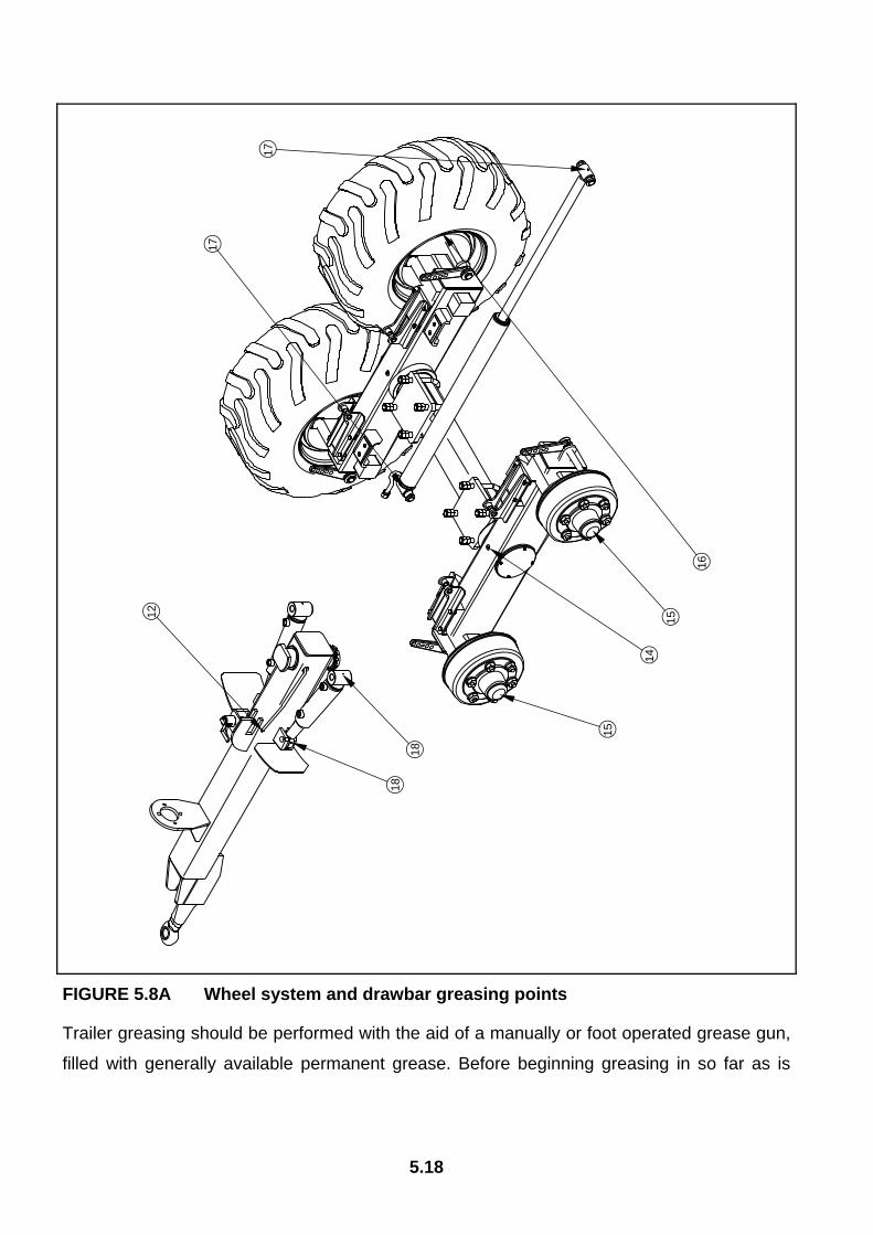
5.18
FIGURE 5.8A Wheel system and drawbar greasing points
Trailer greasing should be performed with the aid of a manually or foot operated grease gun,
filled with generally available permanent grease. Before beginning greasing in so far as is
12
14
15
15
16
17
17
18
18
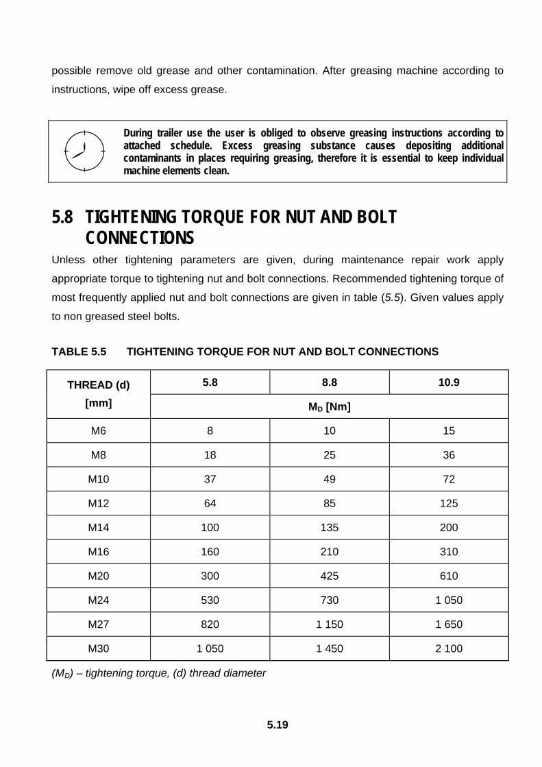
5.19
possible remove old grease and other contamination. After greasing machine according to
instructions, wipe off excess grease.
During trailer use the user is obliged to observe greasing instructions according to attached schedule. Excess greasing substance causes depositing additional contaminants in places requiring greasing, therefore it is essential to keep individual machine elements clean.
5.8 TIGHTENING TORQUE FOR NUT AND BOLT CONNECTIONS
Unless other tightening parameters are given, during maintenance repair work apply
appropriate torque to tightening nut and bolt connections. Recommended tightening torque of
most frequently applied nut and bolt connections are given in table (5.5). Given values apply
to non greased steel bolts.
TABLE 5.5 TIGHTENING TORQUE FOR NUT AND BOLT CONNECTIONS
5.8 8.8 10.9 THREAD (d) [mm] MD [Nm]
M6 8 10 15
M8 18 25 36
M10 37 49 72
M12 64 85 125
M14 100 135 200
M16 160 210 310
M20 300 425 610
M24 530 730 1 050
M27 820 1 150 1 650
M30 1 050 1 450 2 100
(MD) – tightening torque, (d) thread diameter

5.20
FIGURE 5.9A Bolt with metric thread
(1) bolt strength class, (d) thread diameter
5.9 FAULTS AND MEANS OF REMEDYING THEM TABLE 5.6 FAULTS AND MEANS OF REMEDYING THEM
FAULT CAUSE REMEDY
Brake system pneumatic conduit not connected Connect brake conduit.
Damaged pneumatic system connection conduit Replace.
Leaking connections Tighten, replace washers or seal set, replace conduits.
Problem with moving off
Damage control valve or brake force regulator
Check valve, check brake force regulator, replace in the event of damage to whichever elements.
Excessive slack in bearings Checks slack and regulate if needed
Noise in axle hubs
Damaged bearing Change bearing together with sealing ring
Excessive heating of axle hubs
Incorrectly regulated main brake Regulate setting of expander arms
1
d

5.21
FAULT CAUSE REMEDY
Worn brake linings Change brake shoes
Incorrect flow regulator setting Check and if necessary correct
Improper hydraulic oil viscosity
Check oil quality, make sure that the oil in both machines is at the same type. If necessary change oil in tractor or in trailer
Insufficient tractor hydraulic pump output
Check output of tractor pump, if necessary hitch trailer to tractor ensuring proper operation of system.
Damaged or contaminated ram cylinder
Check cylinder ram piston (bending, corrosion), check ram cylinder for tightness (piston seal), in case of need repair or replace ram cylinder.
Damaged hydraulic manifold
Repair or replace damaged manifold section
Excessive cylinder ram loading
Reduce load weight. Comply with operation instruction recommendations
Damaged hydraulic conduits
Check and ascertain that hydraulic conduits are tight, not fractured and properly tightened. If necessary replace or tighten.
Knocking, piston jerking
Worn out ram slide sleeves or pins. Insufficient greasing or excessive dirt contamination. Replace damaged parts.
Damaged or contaminated control cables
Check that cables from control panel are in proper condition without fractures. Check that control lever operates correctly If necessary disconnect steel cable clean or replace.
Incorrect piston ram operation
Damaged control levers Replace damaged part

5.22
FAULT CAUSE REMEDY
Damaged rocker arm bearings
Change bearing, regulate slack and grease rocker pistons and bearing Incorrect suspension
operation Excessive slack in rocker arm bearings
Check and regulate slack in rock arm bearings
5.10 LIST OF BULBS TABLE 5.7 LIST OF BULBS
LAMP BULB
Rear lamp group: left W21L, right W21P
indicator light: P21W brake light: P21W parking light: R10W

NOTES
…………………………………………………………………………………………………………………………………..
…………………………………………………………………………………………………………………………………..
…………………………………………………………………………………………………………………………………..
…………………………………………………………………………………………………………………………………..
…………………………………………………………………………………………………………………………………..
…………………………………………………………………………………………………………………………………..
…………………………………………………………………………………………………………………………………..
…………………………………………………………………………………………………………………………………..
…………………………………………………………………………………………………………………………………..
…………………………………………………………………………………………………………………………………..
…………………………………………………………………………………………………………………………………..
…………………………………………………………………………………………………………………………………..
…………………………………………………………………………………………………………………………………..
…………………………………………………………………………………………………………………………………..
…………………………………………………………………………………………………………………………………..
…………………………………………………………………………………………………………………………………..
…………………………………………………………………………………………………………………………………..
…………………………………………………………………………………………………………………………………..
…………………………………………………………………………………………………………………………………..
…………………………………………………………………………………………………………………………………..
…………………………………………………………………………………………………………………………………..
…………………………………………………………………………………………………………………………………..
…………………………………………………………………………………………………………………………………..
…………………………………………………………………………………………………………………………………..
…………………………………………………………………………………………………………………………………..
…………………………………………………………………………………………………………………………………..

…………………………………………………………………………………………………………………………………..
…………………………………………………………………………………………………………………………………..
…………………………………………………………………………………………………………………………………..
…………………………………………………………………………………………………………………………………..
…………………………………………………………………………………………………………………………………..
…………………………………………………………………………………………………………………………………..
…………………………………………………………………………………………………………………………………..
…………………………………………………………………………………………………………………………………..
…………………………………………………………………………………………………………………………………..
…………………………………………………………………………………………………………………………………..
…………………………………………………………………………………………………………………………………..
…………………………………………………………………………………………………………………………………..
…………………………………………………………………………………………………………………………………..
…………………………………………………………………………………………………………………………………..
…………………………………………………………………………………………………………………………………..
…………………………………………………………………………………………………………………………………..
…………………………………………………………………………………………………………………………………..
…………………………………………………………………………………………………………………………………..
…………………………………………………………………………………………………………………………………..
…………………………………………………………………………………………………………………………………..
…………………………………………………………………………………………………………………………………..
…………………………………………………………………………………………………………………………………..
…………………………………………………………………………………………………………………………………..
…………………………………………………………………………………………………………………………………..
…………………………………………………………………………………………………………………………………..
…………………………………………………………………………………………………………………………………..
…………………………………………………………………………………………………………………………………..
…………………………………………………………………………………………………………………………………..
…………………………………………………………………………………………………………………………………..
…………………………………………………………………………………………………………………………………..


