I .p NASA CONTRACTOR REPORT 177481 b Intelligent Fault Diagnosis and Failure Management d Flight Control Actuation Systems William F. Bonnice Walter Baker 4IASA-C6- 1774&1) INTELLIGLNI EACL'X U88-2 57 90 CAAGYCSIS ANC PAIIUbE BANAGELEA1 CE PLIGHT CChlfiCL ACTUBllCH SYSlELlS Eiaal fieport, Bay 156C - Edr. l)b& [Crager (Charles Stark) Unclas lak.) 9c p CSCL OlC G3/05 0157137 CONTRACT NASP-12404 MAY 1988 a National Aeronautics and Space Administration https://ntrs.nasa.gov/search.jsp?R=19880020406 2018-05-14T05:52:34+00:00Z
Transcript
I .p
NASA CONTRACTOR REPORT 177481
b Intelligent Fault Diagnosis and Failure Management d Flight Control Actuation Systems
William F. Bonnice Walter Baker
4 I A S A - C 6 - 1774&1) INTELLIGLNI EACL'X U88-2 57 90 C A A G Y C S I S ANC P A I I U b E B A N A G E L E A 1 C E PLIGHT C C h l f i C L A C T U B l l C H SYSlELlS E i a a l f ieport , Bay 1 5 6 C - E d r . l ) b & [Crager ( C h a r l e s S t a r k ) U n c l a s lak.) 9c p CSCL OlC G3/05 0157137
ri Intelligent Fault Diagnosis and Failure Management of Flight Control Actuation Systems
William F. Bonnice Walter Baker
THE CHARLES STARK DRAPER LABORATORY, INC. 555 Technology Square Cambridge, Massachusetts 02139
CONTRACT NAS2-12404 MAY 1988
NASA a
National Aeronautlcs and Space Administration
Arnes Research Center Moffett Field, California 94035
ACKNOWLEDGEMENT
This report was prepared by The Charles Stark Draper Laboratory, Inc. under Contract NAS2-12404 with the Ames Research Center of the National Aeronautics and Space Administration.
Publication of this report does not constitute approval by NASA of the findings or conclusions contained herein. It is published for the exchange and stimulation of ideas.
2.2.1 Local Isolation ...................................................... 11 2.2.2 Arbitration ........................................................... 11 2.2.3 Generate and Test ................................................... 13
3 FAULT DIAGNOSIS AND FAILURE MANAGEMENT IN DUAL-TANDEMHYDRAULICACI'UATION SYSTEM .................. 3.1 Introduction .................................................................. 3.2 Dual Tandem Actuator Review .............................................
3.2.1 Operational Dual Tandem Actuators .............................. 3.2.2 Experimental and Prototype Designs ............................. 3.2.3 Comparison of the Three Classes .................................
3.3 Fault Diagnosis and Failure Management Capability .................... 3.3.1 Overview of Dual Tandem FDFM Capability ................... 3.3.2 Specific Description of FDFM Systems ......................... 3.3.3 Actuator FDFM Examiantion ...................................... 3.3.4 Possible FDFM System Improvements ..........................
19 19 21 21 21 25 26 26 27 37 41
iii
TABLE OF CONTENTS (Cont.)
Section Page
4 AN ASSESSMENT OF AI METHODOmES FOR ACTUATOR FAULTDIAGNOSIS ANDFAILUREMANAGEMENT ................... 43 4.1 Introduction .................................................................. 43 4.2 Knowledge Discussion ..................................................... 44
4.2.1 Content ............................................................... 4.2.2 Knowledge Representation ........................................ 4.2.3 Inference and Control ..............................................
4.3 A Survey of AI Approaches of Fault Diagnosis and Failure Management ......................................................... 4.3.1 Five Illustrative AI Systems or Approaches ..................... 4.3.2 Contributions of AI to FDFM ..................................... 4.3.3 Evaluation of the AI Techniques .................................. 4.3.4 Applicability of AI to FDFM ......................................
4.4 The Potential Role of AI in Diagnosing and Managing Actuator Faults ............................................................... 4.4.1 Augmentation of Conventional Techniques ..................... 4.4.2 Accommodation and Management of Uncertainty .............. 4.4.3 Diagnostic System Development ..................................
5 FAULT DIAGNOSIS AND FAILURE MANAGEMENT SYSTEM RECOMMENDATIONS AND RELATED ISSUES .......................... 67 5.1 Recommendations for FDFM Improvement .............................. 67
5.2 Digital Implementation of FDFM .......................................... 69 5.3 Other Possible Benefits of Digital Processing Capability ............... 70 5.4 A Distributed Aircraft FDFM System ..................................... 71
6 SUMMARY AND CONCLUSIONS ............................................ 73
BIBLIOGRAPHY OF ARTIFICIAL INTELLIGENCE DIAGNOSIS LITERATURE ..................................................... 77
Artificial Intelligence Digital Integrated Servoactuator Controller Electrohydraulic Servovalve Fault Analysis Consultant Flight Control Computer Flight Control System Fault Diagnosis and Failure Management Linear Variable Differential Transformer Main Control Valve Rule-Based Flight Control System
.
vi
SECTION 1
INTRODUCTION
Military aircraft control system actuators are high performance components of the flight control system required to quickly and precisely position the control surfaces with a sufficiently damped transient response. In addition, actuators on some control surfaces axe flight critical, requiring high reliability which cannot be achieved in a cost effective manner using an actuator with no redundancy. Therefore, redundancy is used to give the actuators a fault tolerant capability (Le. the capability of accommodating one or more failures). For fault-tolerant actuators, the real-time fault diagnosis and failure management systems must be able to accommodate failures quickly, allowing only small transients. The performance and fault tolerance requirements result in a complex system which requires frequent maintenance and which is difficult to test and repair. As a result, according to one study of the F-16 flight control system (FCS) reported in Reference 1, actuators are second only to sensors of F-16 FCS components in number of failures and the maintenance required.
Some possible approaches to improving the reliability and maintainability of actuators, as well as reducing the frequency of maintenance required, are to improve the reliability of the components, replace components by more reliable alternatives, ani redesign the architecture to make it simpler. These approaches are currently being examined in the technical community. One area that has not been investigated is improving the fault diagnosis and failure management on actuators. Existing military aircraft control system actuators, for the most part, have a very basic capability which results in a high false alarm rate. A study of the maintenance of F-18 horizontal stabilator actuators (Reference 2) found that the second leading cause of maintenance actions (excluding maintenance for reasons other than actuator defects or failures) was for "failed to operate for unknown reasons," requiring 20% of the maintenance actions and 28% of the man- hours. Similarly, "failures which could not be duplicated accounted for 13% of the maintenance actions required for an F-14 spoiler actuator according to a maintenance study described in Reference 3.
Significantly reducing the false alarms produced by the fault diagnostic system on aircraft control system actuators would improve their maintainability and reliability. To reduce false alarms while continuing to accommodate failures quickly with little noticeable
1
transient requires greater sophistication in the fault diagnosis and failure management system. The application of artificial intelligence technology is one approach which may have significant potential in this regard. The effort documented in this report investigates this approach, in conjunction with existing and algorithmic strategies, to aircraft flight control system actuator fault diagnosis and failure management. This study was sponsored by NASA Ames Research Center under contract NAS2- 12404 entitled "Intelligent Fault Diagnosis and Failure Management of Flight Control Actuation Systems." The specific goals of this contract were twofold
To assess the applicability of artificial intelligence methods and techniques to aircraft flight control system actuator real-time fault diagnosis and failure management.
To make recommendations for a fault diagnosis and failure management system based on the investigation of artificial intelligence technology in conjunction with existing approaches.
Implicit in considering the use of artificial intelligence as well as algorithmic methods of failure diagnosis and failure management is the availability of digital processing capability. Some of the more recent actuators use the flight control computer for implementing the fault diagnosis and failure management systems. Placing dedicated microprocessors on future actuators is also presently being investigated.
A brief general review of fault diagnosis and failure management is presented in Section 2. This section provides background for examining the fault diagnosis and failure management systems of aircraft actuators and for assessing artificial intelligence approaches to fault diagnosis. Section 3 examines the fault diagnosis and failure management systems of current operational and experimental dual tandem actuators. Dual tandem actuators were considered in this study because they require significant active fault diagnosis and failure management capability. The results of this investigation will still apply, to a lesser extent, to other actuators. The applicability of artificial intelligence technology for actuator fault diagnosis and failure management is assessed in Section 4. Section 5 presents recommendations for improving the fault diagnosis and failure management capability and the maintainability of dual tandem actuators. Finally, the report is summarized and the major conclusions presented in Section 6.
2
Y
SECTION 2
FAULT DIAGNOSIS AND FAILURE MANAGEMENT BACKGROUND
Fault diagnosis is the process of determining if a failure has occurred and, if so, what component or subsystem has failed. This information is transmitted to the failure management system which determines how to respond appropriately to the failure. The three distinct yet interrelated tasks that make up fault diagnosis and failure management a~ frequently referred to as failure detection, fault isolation, and system recovery and reconfiguration. In this section, each of these tasks is discussed in a general manner, providing a basis for discussing fault diagnosis and failure management in the context of aircraft actuators for the remainder of the report.
2.1 Failure Detection
Failure detection is the operation of distinguishing between the normal and the abnormal (i.e. failed) behavior of a system. The detection process consists of a continuous cycle of monitoring (measurement), information processing, and comparison testing. In general, a failure is detected by monitoring the behavior of a component, subsystem, or system of interest, converting the raw data into a useful form (if necessary), and, finally, by comparing the resultant behavior with a reference model of expected behavior. The outcome of the comparison test is usually a binary decision, Le. "ok" or "failed."
The performance of the failure detection system, therefore, is dependent on information about the system's behavior from the sensors, any knowledge necessary to process this information, and the comparison test. The first two required elements depend on the specific system and the failure detection and isolation approach or approaches chosen, and thus are difficult to discuss in a general manner. With regard to sensors, though, they must provide sufficient information such that any failure that will unacceptably degrade the system operation can be detected. Also note that while sensors are necessary for fault diagnosis and failure management, they also add another source of failures which must also be managed properly to avoid increasing the failure rate of the overall system.
3
However, general methods of comparison testing for failure detection do exist. A comparison test for failure detection consists of a reference model for comparison with the actual system's behavior and a decision rule to distinguish between failed and normal behavior. The reference model of expected behavior can either be a model of the normal behavior of the system or a model of the failed behavior of the system. In the first case, failures are detected by checking for discrepancies between observed behavior and a reference model of the normal behavior. In the second case, failures are detected by checking for consistencies between observed behavior and a reference model of failed behavior. A decision rule is required since the actual behavior will not exactly match the reference behavior due to uncertainty present in the form of sensor and environmental noise and modeling errors between the reference model and the actual system behavior.
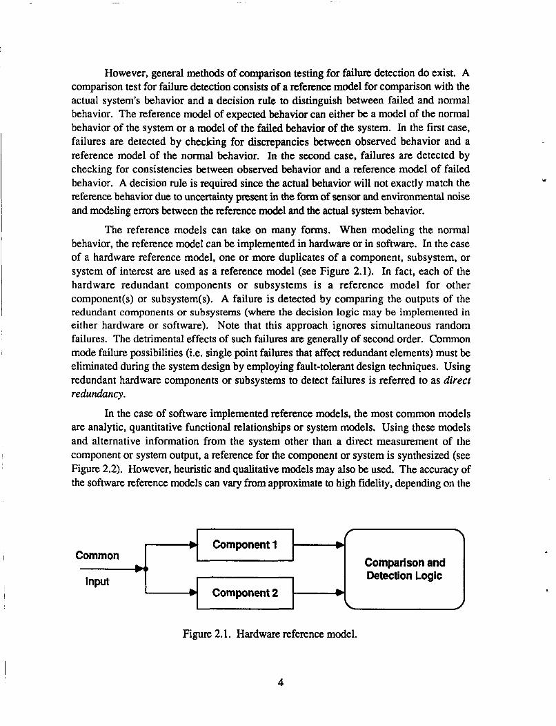
The reference models can take on many forms. When modeling the normal behavior, the reference model can be implemented in hardware or in software. In the case of a hardware reference model, one or more duplicates of a component, subsystem, or system of interest are used as a reference model (see Figure 2.1). In fact, each of the hardware redundant components or subsystems is a reference model for other component(s) or subsystem(s). A failure is detected by comparing the outputs of the redundant components or subsystems (where the decision logic may be implemented in either hardware or software). Note that this approach ignores simultaneous random failures. The detrimental effects of such failures are generally of second order. Common mode failure possibilities (i.e. single point failures that affect redundant elements) must be eliminated during the system design by employing fault-tolerant design techniques. Using redundant hardware components or subsystems to detect failures is referred to as direct redundancy.
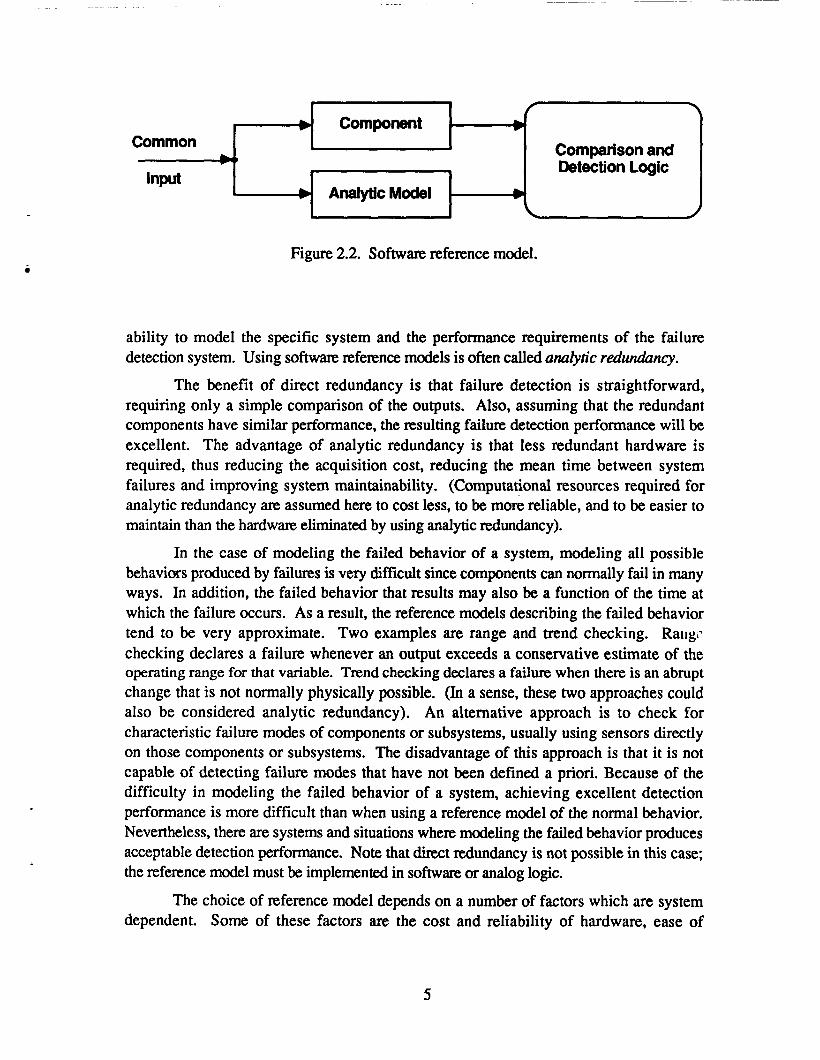
In the case of software implemented reference models, the most common models are analytic, quantitative functional relationships or system models. Using these models and alternative information from the system other than a direct measurement of the component or system output, a reference for the component or system is synthesized (see Figure 2.2). However, heuristic and qualitative models may also be used. The accuracy of the software reference models can vary from approximate to high fidelity, depending on the
b Common
I- \ Component1
Figure 2.1. Hardware reference model.
* Input
Y
Component2 .
4
b Common
Figure 2.2. Software reference model.
f Component b
b b
1
b AnalyticModel Input
b
ability to model the specific system and the performance requirements of the failure detection system. Using software reference models is often called analytic redundancy.
The benefit of direct redundancy is that failure detection is straightforward, requiring only a simple comparison of the outputs. Also, assuming that the redundant components have similar performance, the resulting failure detection performance will be excellent. The advantage of analytic redundancy is that less redundant hardware is required, thus reducing the acquisition cost, reducing the mean time between system failures and improving system maintainability. (Computational resources required for analytic redundancy are assumed here to cost less, to be more reliable, and to be easier to maintain than the hardware eliminated by using analytic redundancy).
In the case of modeling the failed behavior of a system, modeling all possible behaviors produced by failures is very difficult since components can normally fail in many ways. In addition, the failed behavior that results may also be a function of the time at which the failure occurs. As a result, the reference models describing the failed behavior tend to be very approximate. Two examples are range and trend checking. Rangr* checking declares a failure whenever an output exceeds a conservative estimate of the operating range for that variable. Trend checking declares a failure when there is an abrupt change that is not normally physically possible. (In a sense, these two approaches could also be considered analytic redundancy). An alternative approach is to check for characteristic failure modes of components or subsystems, usually using sensors directly on those components or subsystems. The disadvantage of this approach is that it is not capable of detecting failure modes that have not been defined a priori. Because of the difficulty in modeling the failed behavior of a system, achieving excellent detection performance is more difficult than when using a reference model of the normal behavior. Nevertheless, there are systems and situations where modeling the failed behavior produces acceptable detection performance. Note that direct redundancy is not possible in this case; the reference model must be implemented in software or analog logic.
The choice of reference model depends on a number of factors which are system dependent. Some of these factors are the cost and reliability of hardware, ease of
Comparison and Detection Logic
5
accurately modeling the system, computational resources, and the cost in engineering time to design the system. The most important factor is detection performance required. Errors in the reference model will result in incorrect decisions about the health of the system (see Figures 2.3 and 2.4). If the model of normal behavior inadequately describes all possible normal behaviors of the system, a failure will be disclosed when none exists. This is referred to as a false alarm. A failure is missed when the model of normal behavior models the behavior of the system with that failure. When the failed behavior is being modeled, a false alarm results when the abnormal model actually models the normal or unfailed behavior of the system. A missed failure occurs when the abnormal model inadequately models the behaviors resulting from some of the failures.
If a false alarm causes the failure management system to remove the presumed faulty but actually unfailed component, the system performance and reliability is reduced unnecessarily. In addition, the maintenance required would increase in the case of aircraft actuators as the actuator would have to be examined for a failure before a new mission could be flown. If, however, a component failure is not recognized as a failure (Le., a missed failure), the system performance also degrades, perhaps resulting in the system being unable to function.
Given a reference model of expected behavior to perform the comparison, a decision rule is required to distinguish between normal and failed behavior of the system when uncertainty is present. The effect of modeling errors was discussed above. External environmental uncertainty (e.g., change in the loading on the actuator due to turbulence or irregular airflow) can also be considered to be model uncertainty. The effect of sensor noise is to degrade the accuracy with which the actual system behavior can be measured. Even if the normal or failed behavior of the system was modeled perfectly, sensor noise would cause decision errors as the measurement of the system behavior differs from the actual system behavior. This is pictured graphically in Figure 2.5 as a gray area between the normal and failed system behaviors.
The most common decision rule is a detection threshold on the difference between the actual and reference behaviors or some transformation of this difference. Other more sophisticated decision rules use additional information processing before comparing to a detection threshold. In any case, the effect of decision thresholds is to enlarge the modeled regions in Figure 2.6 to account for model, environmental, and measurement uncertainty. For example, if the comparison test is dependent on information from a very noisy sensor, the threshold could be increased to reduce false alarms. Similarly, if there is an environment or situation where the model does not accurately represent the system behavior, the thresholds can be increased to reduce the false alarms. The disadvantage of increasing the detection thresholds is that some types of failures and smaller magnitude failures may no longer be detected. In selecting thresholds, there exists a basic tradeoff between false alarm rate and the type and magnitude of failure that can be detected.
6
normal actuator.-b behavior
(a) modeled versus actual behavior
failed 4- actuator -b
behavior
failed
behavior - actuator-@ - actuator- I normal
behavior I 0 correct diagnosis (no failure) false alarm
(b) failure detection decisions possible based on normal reference model
Figure 2.3. The effect of reference modeling e m r on failure detection decisions when modeling the normal behavior.
7
failed
behavior behavior
(a) modeled versus actual behavior
failed +- actuator ____) - actuator ___) I behavior I behavior
normal
0 correct diagnosis (no failure) false alarm
0 correct diagnosis (failure) missed fault
(b) failure detection decisions possible based on normal reference model
Figure 2.4. The effect of reference modeling error on failure detection decisions when modeling the abnormal behavior.
8
behaviors which are uncertain \ with sensor noise
I failed
behavior
normal
behavior
Figure 2.5. The effect of sensor noise in observing the behavior of the system.
normal model
normal failed
behavior behavior
additional be havio rs tal assumed to be normal 0 modeled normal behavior
with decision thresholds
Figure 2.6. An interpretation of the effect of detection thresholds (normal model only).
9
However, the thresholds do not have to be constant as suggested in Figure 2.6. One frequently used technique when thresholds must be increased because of modeling or environmental uncertainty is to use dynamic thresholds based on the state of the system or the environment, This technique allows better detection of failures when the uncertainty is small. Clearly, the selection of detection thresholds is a major concern in any diagnostic system design.
2.2 Fault Isolation
The process of determining the failed component or subsystem responsible for abnormal behavior, after a failure has been detected, is called fault isolation. The specific information about which component or subsystem has failed is provided to the failure management task so that the effect of the failure on the system may be contained or negated. Therefore, isolation is only needed to the level required by the failure management system. For example, if there is redundancy at a subsystem level, isolating to the component level in the subsystem would be unnecessary for failure management purposes. Isolating to the component level may possibly be useful for subsequent maintenance purposes if no significant increase in system resources (mainly sensors and computational capability) is necessary.
To perform isolation, the sensors must provide sufficient information such that failures of the individual components and subsystems can be differentiated. Note that more information is usually required than in the case of detection. This requirement for sensor information includes that required to differentiate failures of the sensors that provide the information for fault diagnosis from the components themselves. For example, adding a sensor to a component for fault diagnosis, without any additional information available about the operation of the component or sensor, does not provide sufficient information to isolate the failure to the component or sensor; the failure can only be isolated to the component-sensor subsystem. The disadvantage of not being able to differentiate between the sensor and the component is that the reliability of the component-sensor subsystem is less than the component alone.
Isolation also requires knowledge of how the components or subsystems are interconnected and influence each other and, in turn, affect the system behavior. Other related knowledge such as the physical locations of the components and subsystems may also be useful. This knowledge about the functional and physical organization (Reference 4) is needed to transform the behavioral information from the sensors into information about possible failed components and subsystems in the overall system. It may be used either explicitly in the transformation process or be implicit in the design of the isolation system. Finally, with uncertainty present (as discussed in connection with detection), some decision logic is required to differentiate between the possible choices of components and subsystems.
.
10
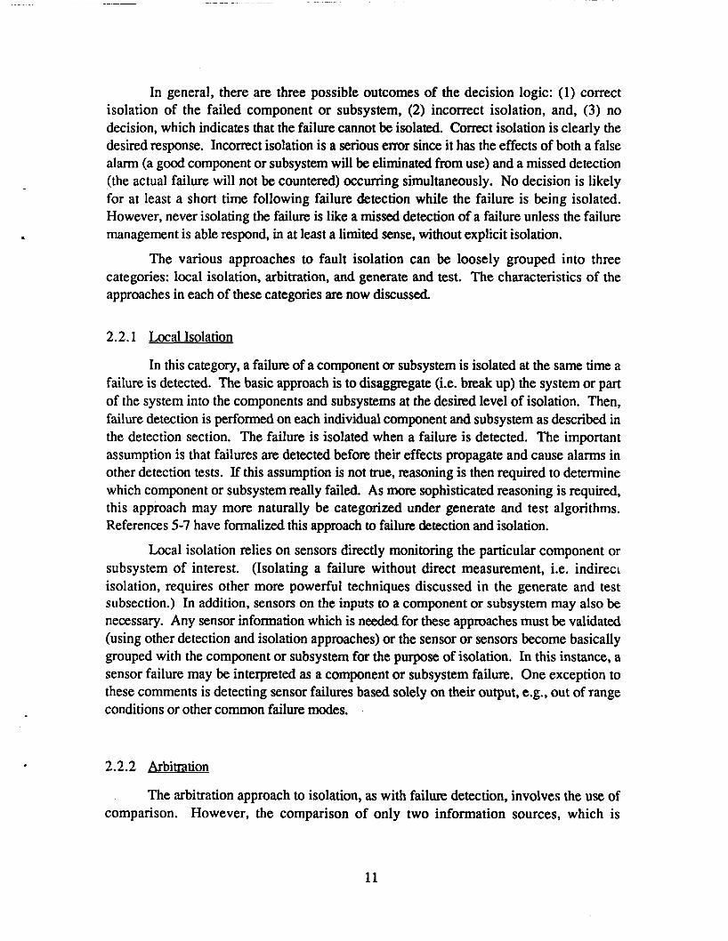
In general, there are three possible outcomes of the decision logic: (1) correct isolation of the failed component or subsystem, (2) incorrect isolation, and, (3) no decision, which indicates that the failure cannot be isolated. Correct isolation is clearly the desired response. Incorrect isolation is a serious error since it has the effects of both a false alarm (a good component or subsystem will be eliminated from use) and a missed detection (the actual failure will not be countered) occurring simultaneously. No decision is likely for at least a short time following failure detection while the failure is being isolated. However, never isolating the failure is like a missed detection of a failure unless the failure management is able respond, in at least a limited sense, without explicit isolation.
The various approaches to fault isolation can be loosely grouped into three categories: local isolation, arbitration, and generate and test. The characteristics of the approaches in each of these categories are now discussed
2.2.1 Local Isolation
In this category, a failure of a component or subsystem is isolated at the same time a failure is detected. The basic approach is to disaggregate (Le. break up) the system or part of the system into the components and subsystems at the desired level of isolation. Then, failure detection is performed on each individual component and subsystem as described in the detection section. The failure is isolated when a failure is detected. The important assumption is that failures are detected before their effects propagate and cause alarms in other detection tests. If this assumption is not true, reasoning is then required to determine which component or subsystem really failed. As more sophisticated reasoning is required, this approach may more naturally be categorized under generate and test algorithms. References 5-7 have formalized this approach to failure detection and isolation.
Local isolation relies on sensors directly monitoring the particular component or subsystem of interest. (Isolating a failure without direct measurement, i.e. indireci isolation, requires other more powerful techniques discussed in the generate and test subsection.) In addition, sensors on the inputs to a component or subsystem may also be necessary. Any sensor information which is needed for these approaches must be validated (using other detection and isolation approaches) or the sensor or sensors become basically grouped with the component or subsystem for the purpose of isolation. In this instance, a sensor failure may be interpreted as a component or subsystem failure. One exception to these comments is detecting sensor failures based solely on their output, e.g., out of range conditions or other common failure modes.
2.2.2 Arbitration
The arbitration approach to isolation, as with failure detection, involves the use of comparison. However, the comparison of only two information sources, which is
11
sufficient for failure detection, is inadequate if either source of information is subject to failure. Arbitration uses more than two sources of information to isolate the failure via some form of majority logic.
The comparisons used in arbitration can either be direct comparisons of information on the same physical or computation parameter or can be indirect comparisons of information on a number of physical parameters that are functionally related. The direct comparison most frequently used is direct redundancy (Le., information from similar redundant components or subsystems) since each of the redundant components or subsystems is subject to failure. The majority logic in this case could be simply threshold tests applied by pairing the components to ascertain which, if any, are too far away from the majority.
Direct comparison can also use redundant information representing the same physical parameter, but emanating from dissimilar sources. The comparisons may be done directly on the measurements, or the data may be weighted towards what is considered to be a more reliable or less noisy source. In some cases, the data from some of the sources may not be a direct measurement of the parameter in question, but rather a synthesis of that parameter based upon other measurements in the system and a model of the system or the physics of the problem (i.e., a form of analytic redundancy).
Note that arbitration may not be necessary when the comparison testing is done using analytic redundancy, as analytic redundancy is generally designed to be sufficiently reliable and can be assumed to be correct. However, both direct and analytic redundancy are sometimes used together in isolating failures. An example is the F-8 program where analytic redundancy provided the third source of independent information.
Indirect comparison uses analytic techniques (Le., another form of analytic redundancy) to compare redundant information representing different, but physically related quantities of the same type that emanate from independent sources. These relationships can be the result of either the physics of the problem or an artificial relationship created using closed loop control techniques. Position and rate measurements fall into the former class. An example of the latter case is force balancing in a scheme where more than three hydraulic actuators are used to support a load at independent points. Because of the functional relationships that exist, more information is available than there are degrees of freedom. This redundant information may be used for isolation.
Arbitration schemes are most efficient when used with sensors, as the outputs are simply compared and isolated in an appropriate manner. When isolating other components or subsystems using arbitration, the sensed information of that isJ used to isolate the failure must be separately validated. For example, if individual sensors are being used to compare three redundant components, at least two redundant sensors would be required on each component. With only one sensor on each component, a sensor failure cannot be differentiated from a component failure. Two sensors are sufficient to differentiate between
12
a sensor and component failure. A sensor failure might be isolated with only two sensors by assuming the component it is measuring did not fail at the same time and if one of the sensors agrees with sensors on the other components.
2.2.3 Generate and Test
Most other approaches to isolation can be considered to be some form of the generate and test paradigm. This paradigm, in the context of fault isolation, can be described procedurally as follows:
(1) Generate a new fault candidate (generally a component or subsystem).
(2) Attempt to verify the hypothesis by testing its ability to explain the observed faulty behavior of the system. A model is required to predict (via simulation) the system behavior resulting from the assumed faulty component.
If the current hypothesis is valid, then go to step (4); otherwise loop back to step (1).
Present the current hypothesis as the isolated fault.
(3)
(4)
The algorithm terminates when the failed behavior predicted by simulation matches (to a reasonable degree) the observed faulty behavior of the system. The hypothesis used for simulation is then declared to be the faulty component responsible for the observed behavior of the system. An alternative procedure is to generate all candidate hypotheses before testing any of them. In this case, the hypothesis that most closely matches the observed behavior is chosen.
The generate and test approach to fault isolation can be interpreted as shown in Figure 2.7. The candidate generation process involves a transformation from a behavioral description of the failure (the symptoms) to a structural one (the faulty components). Tht verification (Le., test) process (fault simulation) is exactly the inverse of the original transformation. Note that each of these procedures relies on knowledge of the system model (Le., its structure, organization, and behavior).
Conceptually, this procedure employs two basic modules referred to as the generator and the rester (Reference 8). The solution algorithms differ with respect to these modules. The overall efficiency of the algorithm (as measured by the number of iterations or time required to arrive at a solution) depends critically upon the efficiency of the generator and the tester. The power of a specific generate and test procedure to provide correct answers results from its ability to generate accurate hypotheses and to discriminate effectively among competing hypotheses.
13
Candidate Generation
u /I+/ Simulation
I I \
. .
Structure Model (faulty components)
Figure 2.7. Generate and test approach to fault isolation.
2.2.3.1 Candidate Generan 'on
To guarantee that a generator will produce the correct solution to the fault isolation problem, the generator must be complete, Le., able to produce all possible hypotheses. A necessary condition for completeness requires that the set of all possible solutions be enumerable and finite. If there are possible solutions which cannot be produced by the generator or if there are an infinite number of possibilities, then the generator is said to be incomplete. An incomplete generator may or may not produce a correct hypothesis.
The effectiveness and efficiency of the candidate generation process may be improved through guidance. The simplest form of guidance restricts candidate generation so that the same hypothesis is never proposed more than once. Generators with this property are said to be nonredundant. In some situations, no further guidance is possible and the optimum generator is nonredundant, but otherwise arbitrary in its selection of candidates. Under these conditions, the algorithm is referred to as exhaustive search.
For a problem having a single solution among a complete set of N possible solution candidates, exhaustive search will arrive at the correct solution in N/2 iterations, on average. For many important problems however, the quantity N is characterized by
t
14
exponential growth relative to linear changes in the problem size. Although exhaustive search is simple and straightforward, it is a "blind" method of candidate generation and, as such, is not generally amenable to complex problems.
Useful information normally exists which can be exploited to substantially reduce the number of iterations required (on average) to arrive at a solution. Knowledge about the problem domain in combination with information returned from the tester (the error estimate or error signal) may be used for this purpose. Generally speaking, the more that is known a priori about the problem domain and the more sophisticated the runtime verification process and associated error signal are, the better the candidate generator will be. In effect, a priori and runtime information serve to limit the number of candidate hypotheses that must be considered.
Candidate hypotheses are removed from consideration in two different ways. Candidates may be eliminated from consideration permanently, based on the evidence at hand. Alternatively, candidates may be temporarily removed from consideration as a consequence of prioritizing the remaining possibilities. Prioritization schemes organize remaining candidates so that those hypotheses which are most likely to succeed are tested first. Prioritization schemes may be heuristic in nature, or optimal with respect to the current state of the solution process.
While candidate generation can be done in real-time, in most present diagnostic systems, a set of possible fault candidates are enumerated a priori, eliminating the need for real-time candidate generation. This is normally done because the total number of reasonable fault candidates which must be considered is small in number. This is true for even large systems where the fault diagnosis capability is broken down by subsystems. There are, however, a number of recent systems which do generate the candidate hypotheses in real-time. These systems are a result of attempting to incorporate some artificial intelligence technology into the diagnostic process and therefore will be discuswl further in Section 4.
2.2.3.2 Hvpothesis Testing
The function of the tester is to determine whether the current hypothesis is valid. Conceptually, testing often involves two distinct subtasks: (1) simulation and (2) comparison testing. Simulation is the process of examining the logical consequences of a particular hypothesis with respect to a given knowledge base or model. Typically, simulation is carried out by numerical modeling. The simulation result is subsequently compared with, for fault isolation, to the actual behavior of the system.
One significant complicating factor in simulating the effect of the fault hypothesis on the system behavior is that the form, size, and time of the failure all have an important effect on system behavior. There are some failm detection and isolation algorithms which can isolate failures without knowing specifically the behavior of the failed component or
15
subsystem. However, most hypothesis testing algorithms must estimate this information, search over some space of possible failure behavior, or some combination of these two. If search is used to identify the failed behavior, the computational effort required may be greatly increased. In this case, fault identification is basically required, which is much more difficult.
It is frequently the case that no hypothesis satisfies the requirements of the comparison test perfectly. This may be the result of imperfections in the simulation process (modeling errors), noise in the environment, or of uncertainty in decision making. The generate and test algorithm may terminate when the best hypothesis (i.e., the hypothesis having the smallest associated error) is found, or when the error falls below a prescribed threshold value. The quality of the decision process impacts the overall performance (especially the accuracy) of the solver to a significant degree.
2.2.3.3 Benefits and Disadvantages
The fundamental advantage of generate and test approaches is that they can be powerful, using a model of the system to isolate faults for which there is limited or nonexistent direct information. The result is fewer sensors and components required for fault diagnosis. However, the generate and test procedure suffers from the primary problems associated with all indirect problem solving techniques: uncertain convergence characteristics, variable solution time, and some degree of arbitrariness. Present generate and test algorithms, though, mitigate this somewhat by limiting the fault candidates to an a priori enumerated set. Still, some algorithms need to estimate the failed behavior of the component or subsystem or search over some space of possible failed behaviors (in addition to searching over possible component failures) since faults usually have many possible failed behaviors. In any case, the computational requirements for these approaches are usually significantly greater than other isolation approaches.
2.3 Failure Management I
Failure management is the process of evaluating the effect of a previously detected and isolated failure and then responding to the failure to recover some level of system performance. The level of system performance possible is a function of the system capability following a failure (which is in turn a function of the system redundancy). Very generally, failure management can be consided to consist of the following steps:
(1) Given a description of the system's abnormal behavior and altered structure, determine the system's current level of capability.
(2) Compare the current system capability with the prescribed system performance objectives and alter the performance objectives as close as possible to the original objectives but within the current system capability.
16
1
(3) Determine and execute the sequence of response action which will minimize the discrepancy between the present system performance and the modified performance objectives.
At the present time, with few, if any, exceptions, failure management systems take the fault isolation information and simply execute a predetermined sequence of response actions. The first two steps and most of step 3 are performed in advance when the failure management system was developed and are implicit in the transformation from isolation information to response actions.
The response to a failure can be divided into two tasks: system reconfiguration and recovery. Reconfiguration is the process of negating the failed element, so that it no longer has any influence on the system behavior, reassigning the function of the failed element to another redundant element or elements, and restoring the performance of the system. The isolation and reassignment may be logical, in the sense that there are multiple sources for a parameter and erroneous data emanating from the failed element is simply ignored; it may be electrical, either by removing power from the failed element such that its outputs go to a null state or by electrically switching in a replacement element; or it may be physical, in the sense that the structure of elements are physically changed by a monfiguration mechanism. While these methods of reconfiguration are the most common, changing the software controlling the system is often necessary to take advantage of other functional redundancy or capabilities not normally used or to improve or restore the performance of the system. One example is altering the control system to account for the changed system.
Recovery includes other actions taken to c m t or minimize the effect of a failure in lieu of or in addition to those taken to reconfigure the system. These actions are sometimes required to
shut down the system operation, when sufficient capability to perform is no longer available, in such a manner that the system is not lost and the damage to the systen. is minimized. oppose the effect of the failure while reconfiguration is occurring.
bring the state of the system back to a condition where the reconfigured system can operate satisfactorily.
Recovery is not needed for aircraft actuators as they are required to be able to reconfigure quickly so that a failure only causes a small transient. Therefore, the subsequent discussion on failure management will concentrate on reconfiguration.
17
SECTION 3
FAULT DIAGNOSIS AND FAILURE MANAGEMENT IN DUALTANDEM HYDRAULIC ACTUATION SYSTEMS
3.1 Introduction
Three levels of real-time fault diagnosis and failure management (FDFM) capability are possible on aircraft control surface actuators. The most basic capability (if any exists at all) is simply to detect that the actuator has failed so that the pilot may be notified. The benefit of notifying the pilot is that continued operation with a degraded vehicle may be undesirable or prohibited. The next level of capability is to diagnosis certain component or subsystem failures so that their effect can be neutralized by activating appropriate reconfiguration devices. The objective of neutralizing the effect of a failure is to allow the actuator and the aircraft to operate more efficiently and effectively. The most sophisticated fault diagnosis and failure management capability is required for actuators which are fault tolerant, i.e., capable of automatically adapting, in a well-defined manner, to failures of their own elements so as to continuously maintain a specified level of system performance. In this case, the FDFM performance requirements are demanding because even small failure transients can have a significant effect on the aircraft. For example, on high-speed, high-performance aircraft, transients which result in as little as 3 degrees of surface movement may result in mission failure, if not aircraft loss (Reference 1).
Hydraulic actuators with fault tolerance capability are often differentiated based on the level of redundancy associated with the power ram. The power ram is a mechanical device which converts hydraulic pressure into a force that positions the control surface via a connecting rod attached to the surface. The position of the surface is controlled by directing the hydraulic fluid into ports or openings on either side of the piston or pistons of the power ram (see Figure 3.1). A simplex actuator relies on only one hydraulic system and piston in the power ram. While other parts of the actuator which control the hydraulic fluid driving the power ram may be fault tolerant, a failure of either the hydraulic system or the power ram would disable the actuator. Therefore, for actuators on flight critical control
eitmmmo PAGB BLWK NOT FILMED 19
ports for hydraulic fbw to control the position of the pistion
connecting rod attached to the bad piston
Figure 3.1. Power ram.
surfaces, power rams with two pistons in tandem where each piston is supplied with a separate hydraulic system are used (see Figure 3.2). These actuators are referred to as dual tandem actuators.
Dual tandem actuators have the greater fault tolerance capability and, therefore, require the more sophisticated active fault diagnosis and failure management capability. Therefore, this report focusses on the fault diagnosis and failure management of this class of actuators. Nevertheless, the results of this study should be applicable to other configurations to some extent.
Section 3.2 briefly reviews current operational and experimental high performance dual tandem actuators. The following subsection examines the fault diagnosis and failure management capability of these dual tandem aircraft actuators. This section provides a basis for evaluating alternative approaches to actuator FDFM.
Figure 3.2. Dual tandem power ram.
20
3.2 Dual Tandem Actuator Review
The dual tandem actuators examined far this study can be divided into three general classes. The first class consists of actuators presently used in military aircraft. The other two classes are simpler experimental and prototype designs. The actuators in these classes differ in the manner in which the hydraulic flow to the power ram is controlled. Each of the types of actuators are briefly described and compared. The additional components required for fault diagnosis and system reconfiguration are discussed in the subsection on FDFM capability.
3.2.1 ODe rational Dual Tandem Actuators
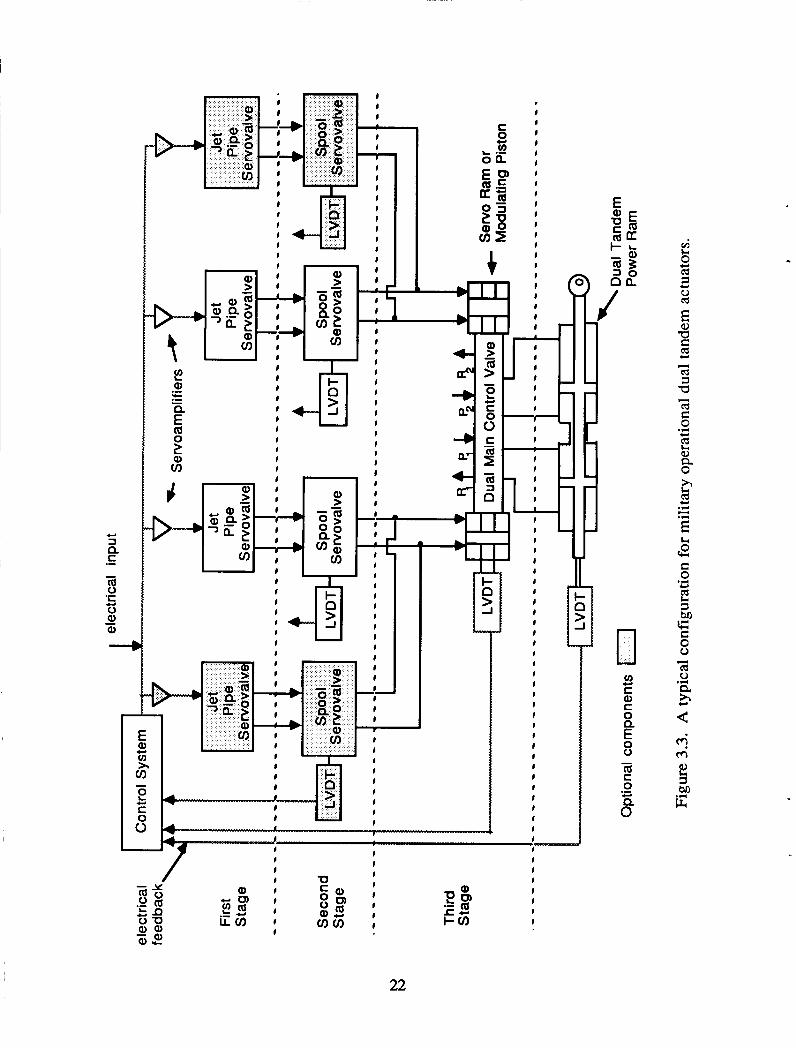
A configuration which is typical for dual tandem actuators is shown in Figure 3.3. While current dual-tandem actuators may differ from this configuration in some manner, it is sufficient to give a general understanding of these actuators. These actuators use three stages to convert and amplify an electrical or mechanical input into controlled hydraulic flow to the power ram. The fmt stage normally consists of three to four jet pipe or flapper nozzle servovalves which convert the input to a differential pressure to drive the second stage servovalve spool. The fmt two stages are often combined into a single unit called a two-stage electrohydraulic servovalve (EHSV). With these devices, the spool position is controlled by feedback (normally mechanical) of the spool position to the first stage. The schematic and the operation of a two-stage EHSV is shown in Figure 3.4. The second stage then meters hydraulic flow to modulating pistons or servo rams which in turn position the dual main control valve (MCV). The second stage may alternatively position the MCV mechanically. The MCV controls the hydraulic flow to the power ram. There is closed-loop control of the power ram position which may be implemented mechanically, in analog circuitry, or using digital processing. In the case of mechanical control, the linear variable differential transformers (LVDTs) are replaced by linkages unless required fol other purposes.
3.2.2 Exmrimental and Prototye Desims
One experimental class of actuators consists of those systems which have eliminated the MCV, using 2 to 4 two-stage EHSVs to control the hydraulic flow to the power ram directly (see Figure 3.5).
The other class considered here is the direct drive actuator which uses electrical motors to control the position of the MCV directly (see Figure 3.6). These direct drive actuators simplify the actuator design and eliminate the conventional two-stage amplifier stage. These designs are suitable for high pressure application since the actuator
21
I I I I I I I I I I I I I I I I I I I I I I
I I I I I I I I I I I I I I I I I I I I I I I I I I I I I
H cd 1 a
22
The principal of operation is as follows:
FIRST STAG E
-3- SECOND STAGE
Hydraulic fluid flows through the jet pipe to the first stage hydraulic amplifier.
The first stage amplifier consists of the transmitter orifice on the end of the jet pipe and the two receiver orifices below the transmitter orifices, slightly off-set to the right and left.
With the jet pipe in the normal position and no electrical signals applied, the pressure and flow in both receiver orifices is equal and the second stage spool valve remains stationary.
By deflecting the jet pipe to the right or left, the pressure and flow relationship between the right and left receiver orifices is changed, which results in a second stage valve spool displacement and therefore a hydraulic flow command change to the actuator.
The jet pipe position is controlled by the force of the electromagnetic fields generated by the valve drive currents in valve coils #1 and #2, the permanent magnets on the jet pipe deflection bar and the mechanical feedback spring.
Figure 3.4. Principle of operation of electrohydraulic servovalve (taken from Reference 9).
23
4 x
24
e Servoamplifiers
Dual Main Control Valve
Power Ram
Figure 3.6. A typical direct drive dual tandem actuator.
interleakage is significantly reduced with the elimination of the two-stage EHSVs. The motivation for using higher hydraulic pressure is to reduce the size of the actuator which is attractive given the thin wings of modern military aircraft.
3.2.3 ComDarison of the Three Classes
The operational class of dual tandem actuators use more stages for amplification This allows smaller f i t stage servovalves to be used which reduces the hydraulic power loss associated with these devices. The benefit of an MCV is that it isolates the effect of load from the servovalves and produces better dynamic response (Le., more stiffness). The use of an MCV also results in better failure performance as the actuator does not lose force output capability with loss of an EHSV, although it may still lose some bandwidth.
The removal of the MCV in the first class of experimental designs simplifies the actuator and eliminates another source of failures. However, this class requires more powerful two-stage servovalves which results in a higher constant power loss and higher failure transients. In addition, these actuators have lower chip shearing capability and slower dynamic response.
Direct drive electrical motors used on the direct drive experimental actuators are necessary with higher hydraulic pressure application as the constant hydraulic power loss with standard EHSVs would be too high. Electric motors have become significantly more
25
powerful since the development of motors using rare-earth metal, making this actuator design feasible. Internal leakage around the piston becomes a more significant problem, though, with the higher hydraulic pressure, and the dynamic performance is slower than the other two classes.
3.3 Fault Diagnosis and Failure Manage ment CaDab ilitv
The fault diagnosis and failure management capability of these three classes of actuators was determined by examining the FDFM system on six representative actuators:
F- 16 integrated servoactuator
F-18 stabilator actuator
V-22 swashplate actuator
Digital integrated servoactuator controller (DISAC) actuator developed by the Boeing Military Airplane Company and Moog Inc.
Bell 4-valve (Bell-4V) actuator Dynamic Controls direct drive actuator developed for the Air Force Flight Dynamics Laboratory
The F-16, the F-18, and the V-22 actuators are presently in use on recently developed military aircraft. Presumably, they represent the best of actuators presently in use. The Bell-4V and the DISAC actuators are of the experimental type which have eliminated the MCV. The Bell-4V actuator was developed for a flight test program while the DISAC actuator is a prototype designed to test microprocessor-based control, fault diagnosis, and failure management. The Dynamic Controls direct drive actuator is a proof-of-concept prototype.
The FDFM capability of these actuators is frst described in general. Then the specific FDFM systems on the actuators is presented followed by a discussion of their capability. Finally, some improvements for actuator FDFM systems are suggested.
3.3.1 Overview of Dual Tandem FDFM Capabilitv
In general, FDFM for these actuators is based on the local isolation approach described in Section 2.2.1. The actuator is conceptually disaggregated (i.e. broken up) into component or subsystem elements for which there is a failure response. Then, failure detection is performed on each individual element. When a failure detection test is exceeded, a failure is isolated immediately to the monitored element. The important assumption is that failures are detected before the effect of the failure propagates and causes alarms in other detection tests. Alternatively, any downstream detection tests must allow sufficient time for upstream component failures to be detected by their corresponding test.
26
If the propagation of the effect of the failure is not handled properly, the failure may be isolated to an incorrect component. Careful consideration of the effects of failure propagation is important because, given this approach, information is not shared among the detection tests. For each failure detection, there is a straightforward failure management response which at best may contain some logic to account for other previous failures that been detected and removed from operation.
The three approaches to failure detection used are self-test, direct redundancy, and analytic redundancy. Briefly reviewing Section 2.1, self-test relies upon information that can be obtained directly from or within an element itself to detect common or characteristic failure modes. Direct redundancy compares the outputs of like components to detect and isolate failures where analytic redundancy, as used in the case of actuators, compares the output of a component to an analytic model.
There are passive and active failure responses used on these actuators. In the passive case, the actuator is designed to handle the failure without explicit failure detection and failure response by relying upon the redundancy designed into the system. Active responses reconfigure the system to neutralize the effect of a failed component or subsystem and, in some cases, to recover the original performance.
3.3.2 Specific Description of FDFM Svstems
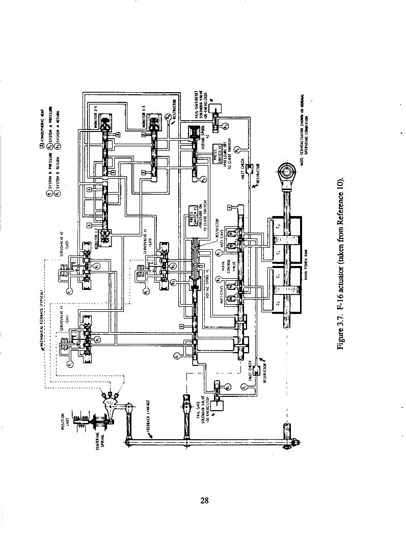
The F-16 actuator (References 10 and ll), shown in Figure 3.7, uses three two- stage electrohydraulic servovalves to drive an MCV. In the normal mode of operation, only two of the servovalves are used to drive the MCV with the third servovalve in an active standby mode. The input to the servovalves is a function of the electrical command and the mechanical feedback of the power ram and MCV spool positions (MCV spool position feedback provides power ram rate feedback). There are current monitors on the outputs of servoamplifiers which are directly compared to detect amplifier and servovalve coil failures. If a failure is detected in either a’servoamplifier or a coil, that command circuit is replaced by a standby amplifier driving the secondary coil of the servovalve in the failed circuit (if the standby amplifier is not the failed component). This part of the FDFM logic is implemented in an analog computer with a switch providing the reconfiguration capability. Servovalve failures are detected by hydraulic logic comparing the output differential pressures of the first stages of the servovalves. The hydraulic voting spool causes the MCV modulating piston control to switch to the standby servovalve if one of the two primary servovalves has failed. If the standby servovalve fails, the two primary servovalves are locked on. The final failure detection test used on the actuator is a comparison of the actual actuator performance using a power ram position sensor and a model of the actuator in the computer. The response to a failure detected with this test is to activate two solenoid valves that allow the feedback centering spring to command the actuator to zero position.
27
28
The F-18 stabilator actuator (Reference 12) has four single stage EHSVs which are paired to allow direct failure detection by comparing their output pressures using quad differential pressure sensors on each pair of servovalves (see Figure 3.8). EHSV failures detected in this manner are contained by a solenoid valve which shuts off the hydraulic supply to that pair of one-stage servovalves. Each one-stage EHSV has four coils with a coil on one servovalve connected in series with a coil on the other servovalves. Each of the four series of coils are driven by a separate amplifier. One of the four digital flight control computers (FCC) is interfaced to one and only one amplifier, supplying the current command to the amplifier-coil combination. With this flux-summing arrangement, the inputs from the four amplifiers are effectively added. The current from each amplifier is compared to a digital model of the amplifier to detect amplifier or coil failures. If a failure is detected, that electrical channel is disabled, The actuator is able to meet the performance specifications with two coil failures so no failure management is necessary. More than two coil failures results in the hydraulic flow to both pairs of EHSV being shut off, allowing the MCV to be controlled mechanically. Each pair of EHSVs drives one piston of a dual tandem modulating piston design. The dual tandem modulating pistons is mechanically linked to the MCV to control its position. (This design is motivated by the desire to incorporate mechanical reversion capability) There are quad LVDTs on both the servo ram and the power ram, which are used for control. Each LVDT is connected to one of the four FCCs. Each FCC in turn, drives one of the servo amplifiers. Failures of these sensors or the command from the FCC are detected both by the servoamplifier current failure detection or by comparing the position of the servo ram with a model. Sensor detection by direct comparison is not possible because the quadruplex digital FCC system does not allow any cross channel communication. The loss of hydraulic power is negated by a bypass/damping valve which equalizes the pressure on either side of the power ram pistons, allowing the control surface to float.
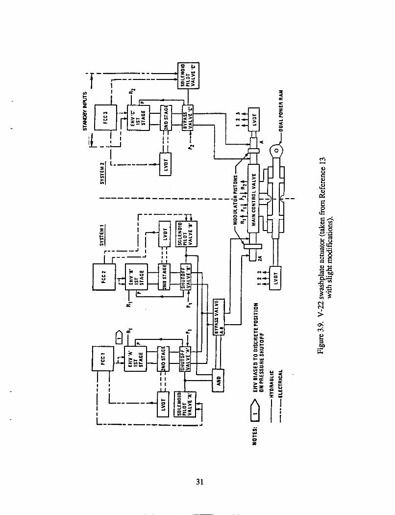
The V-22 actuator (Reference 13) controls the MCV with two unbalancci modulating pistons (see Figure 3.9). Two two-stage EHSVs drive one modulating (mod) piston with the third two-stage EHSV driving the second mod piston which has half the area of the first mod piston. The servovalves are commanded separately by the three FCCs. The current driving the EHSVs is measured and compared to a digital model in the FCCs for servoamplifier and servovalve coil failure detection. EHSV failures are detected using the position sensor on the second-stage spool of each servovalve for EHSV failure detection. Failures of LVDTs including the triplex LVDTs on the MCV and the power ram are detected using a self test approach since there is no cross channel comparison used in this case either. The response to a failure of a servoamplifier, a servovalve coil, a servovalve, or an LVDT is the same: activate the appropriate shutoff valve or bypass valve to disable the hydraulic flow to the corresponding servovalve.
29
1 2 3 4
Dual Singb
Hydraulic stage Eloctro. Note: Setvdoop
closure shown for oniy one channel. 'I / & w a t v e s (2)
e, Sobnoid
r P1 R i p2 R 2 LVDT
CAS Ram I I P1 R1 R2
I I 1 LVDT '
I
U I =System pressure 1 I .Dual Master Control Valve
Figure 3.8. F-18 stabilator actuator (taken from Reference 12).
30
31
The Bell-4V actuator (References 14, 15 and 16), shown in Figures 3.10 and 3.1 1, uses four two-stage flapper valve EHSVs to meter the hydraulic flow directly to the dual tandem power ram. An open EHSV coil or drive wire failures are detected by comparing the EHSV current to a simple analog model. If a failure is detected, the particular EHSV is disengaged using a solenoid valve. Other EHSV failures are detected by directly comparing the position of the second stage spool of the four servovalves. Because the Bell-4V is able to accept a hardover servovalve failure (the control system causes a bypass around the piston with the failed servovalve channel), the detection thresholds are set so that only large failures are detected. The advantage is reduced false alarms. If both channels driving a piston have failed, a bypass valve is activated for that piston. The FDFM system is implemented in analog logic.
The DISAC prototype actuator (Reference 17) was developed to be controlled and managed by two microprocessors (see Figure 3.12). It differs from the Bell-4V actuator in that only two EHSVs are used. In the primary operating mode, each microprocessor controls one channel (i.e., EHSV and bypass valve). However, if a microprocessor failure is detected using some self test, that microprocessor relinquishes control of its channel and the other microprocessor controls both channels. To accomplish this design, both microprocessors have access to the same information on each channel through the use of duplicate sensors. One sensor interfaces to each microprocessor. In addition, both microprocessors are able to operate each EHSV and bypass valve using separate coils in each component. Logic exists to keep both microprocessors from attempting to control the same component simultaneously. Failure detection on this actuator consists of comparing the measured position of the second stage spools to fast and slow models of the EHSV to detect EHSV failures. In addition, LVDT failures are detected using self test. The failure management response could be either to neutralize the channel with the failed component or allow the other microprocessor to take over operation of the channel. The precise redundancy management logic is not detailed in Reference 15. One unique feature of this actuator is the use of position switches on the bypass valve to verify its operation, presumably during preflight testing. Bypass valves failing open is a latent failure as it cannot be observed during normal operation. Preflight testing at least verifies its operation occasionally.
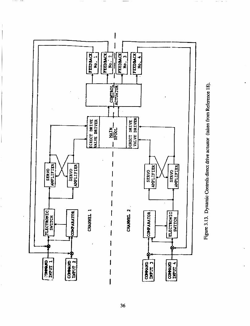
The Dynamic Controls direct drive actuator (Reference 18), shown in Figure 3.13, uses two servoamplifiers to provide current to each direct drive motor. Each amplifier drives one of two coils in each motor. Servoamplifier failures are handled by using a cross-strapping design that opposes the bad channel with the good channel. Failures in the command inputs and the LVDT on the power ram are detected by comparing the feedback error in two channels. The response is to disconnect the command from the motor with the detected failure. An LVDT failure is opposed using the cross-strapping design again. The FDFM requirements for direct drive actuators ~IC less than the other actuators because the motor fails in benign ways such that an active response to neutralize the failed is not required.
32
U 3 a 'p
33
34
FLIOHT 8tllAL O A l A W8 D A l A U CONTROL
( FCC ) COMPUTER
& w COll... COII... 1 I
..
I J. D l S A C
..I- 1".
I D I S A C -. .I.*- .- ).I.
I
I A "I B
I' 1 , I n 1 1 II I
c ..l..C1
ACTUATOR 1
HYDRAULIC 1
ACTUATOR 2
HYDRAULIC 2
Figure 3.12. DISAC actuator (taken from Reference 17).
35
I
d
rt
I u I
I +-
36
3.3.3 Actuator FDFM Examination
The FDFM systems on these six actuators are examined with respect to their ability to diagnose and respond to various component failures, their performance, and their logic implementation.
3.3.3.1 Commnent Failure Diamosis and Management
The FDFM systems for the six actuators are summarized in Table 3.1. The FDFM systems are generally able to detect and reconfigure the actuators for servovalve, electrical and sensors failures. No reconfiguration capability in general exists to address failures of the MCV and the power ram. The most likely common mode failure for the MCV and the power ram is for them to jam; the upper stages driving the MCV or power ram are designed with properly specified chip shearing force capability, overpowering the jam in most cases. No reconfiguration capability exists for direct drive electrical motors either since their most common failure modes are shorts or opens in their coils. The actuator is still able to operate with these types of failures of the motors although the chip shearing capability and, perhaps, the dynamic response will be degraded because of the reduced force capability of the two motors.
Also generally not addressed are failures of the FDFM system itself, including the implementation of the logic and the reconfiguration components. This is especially true for FDFM logic implemented hydraulically or in analog circuitry as there is no redundancy in these cases. If the hydraulic or analog logic fails, the result could either be to declare a failure of some other component (incorrect isolation) or to detect no failure at all (missed failure). The latter case allows the actuator to continue operation but creates the potential situation where another failure occurs and the FDFM system is unable to respond to it, perhaps causing the loss of the aircraft. In the first case, the operation of the actuator may be degraded or shut off because of the failure response or responses chosen by the failed FDFM logic. Unless unnecessary loss of the actuator is critical because of the mission situation, this case is preferable since at least some failure is detected. The digital implementations of the logic are more fault tolerant since the logic is distributed to more than one processor.
Failures of reconfiguration components such as bypass and solenoid valves and switches are, in some cases, impossible to detect. This is the case because they are on-off devices. For example, if such a device which is normally off becomes stuck in that position, the failure cannot be detected since the failure does not adversely affect the operation of the system (i.e. a latent failure). When and if the component is commanded to turn on or if the component fails to a different condition than it is being commanded, the
37
I- n 3
38
failure can be detected. Since only one of the actuators studied provided backup or redundant components for these devices (a backup coil on the DISAC actuator bypass valves), they apparently are sufficiently reliable that FDFM is not required for these components. Nevertheless, as suggested by the redundancy management on the DISAC actuator, preflight testing of these devices would reduce the likelihood of flying with a failed reconfiguration device of this type.
Some failures are handled using inherent capability within some actuators, requiring no explicit FDFM system. For example, the Bell 4-valve and the F-18 actuators can accommodate a hardover servovalve failure with only closed-loop control. With these actuators, the control system will cause the other three servovalves to move to oppose the failed servovalve. The result will be a force-fight situation with degraded, but acceptable, performance. Similarly, the cross-strapping amplifier design on the Dynamic Controls direct drive actuator simply offsets the effect of one amplifier failure with the opposite current in the other amplifier. Force fighting is characteristic of many passive failure responses. The advantage of this approach is no that FDFM logic or reconfiguration devices are required. The disadvantage is that excess capability greater than normally required is necessary, needing and using much more power than necessary. In addition, force fighting will cause performance degradation and mechanical fatigue, increasing the wear and tear on the system and the likelihood of subsequent failures. In addition, unless the detection thresholds account for the effect of force fighting, false alarms will occur.
3.3.3.2 Imdemen tation
The FDFM logic is implemented in three basic ways: hydromechanically (the F-16 actuator), in analog circuitry (the F-16, the Bell 4V, and the Dynamic Controls direct drive actuators), and in digital software (the F-18, the V-22, and the DISAC actuators). In the latter case, the digital logic can reside either in a central FCC or in a local microprocessui There is a trend from hydromechanical and analog logic to digital logic. The disadvantages of hydromechanical logic are the additional cost, power, size, weight, and hydraulic complexity required. One implication is decreased maintainability. In addition, this logic can only be used for direct redundancy failure detection, must be simple, and cannot be modified without a major effort (i.e., little flexibility). Analog logic overcomes most of these disadvantages. However, the FDFM capability possible is basically limited to self test and direct redundancy approaches, although a limited analytic redundancy capability is possible. Digital implementation of the FDFM system offers the potential for the best FDFM capability since all of the detection approaches - self test, direct redundancy, and analytic redundancy - can be easily and precisely implemented. In addition, the potential for fine tuning of the FDFM logic exists. The benefits of using a local microprocessor rather than relying on the central FCC are alleviating the system management burden of the FCC, less cabling to the FCC, distributed processing allowing increased computational capability for FDFM and other tasks, and better digital control (Reference 19). However,
39
the impact of the local environment (e.g., heat, vibration, etc.) on the microprocessor is a problem that is still being investigated (Reference 19).
While digital implementation of the FDFM system offers the greatest capability, all of the digital FDFM designs above had limitations imposed on them by the design of the fault tolerant computer system. In order to interface with the quad FCC system on the F-18, all the electrical components and sensors were quad redundant, creating four electrical channels. Each of the four redundant components or sensors interfaces with only one FCC. No cross talking between systems was allowed, eliminating the most natural approach of failure detection: direct comparison of the redundant components. The failure response is to eliminate the entire electrical channel if any one component or sensor in the channel fails. The V-22 system is similar to the F-18 except that a triplex FCC is used. The DISAC actuator also has problems with using the redundancy available with their "brickwall" design (Le., no communication between the two local microprocessors). The benefit is simpler FDFM computer architecture at the expense of more components and an increased failure rate. However, reliable communication between computer channels may not be possible without significantly increased complexity and decreased reliability.
3.3.3.3 FDFM Perfoxmance
The fault diagnosis performance for these FDFM systems is determined by the performance of each individual detection test. The resulting performance is partially determined by the type of detection test and the thresholds used. Self test, used to detect microprocessor failures on the DISAC actuator and some LVDT failures, is only able to detect certain specific failures. Normally, the direct and analytic redundancy approaches result in better detection performance, since modeling the normal behavior of a component or subsystem is generally easier, more accurate, and more comprehensive than modeling the failed behavior. In practice, the thresholds set using direct and analytic redundancy are large for actuator applications. Reference 18 states that thresholds for fly-by-wire actuators are often set to 30 to 50% of the maximum level possible with a hardover failure. As a result, only large failures are being detected with the other failures being compensated for by the control system. Apparently, smaller thresholds are not possible without an excessive false alarm rate. This may be true because of significant differences in the dynamics of two components in the case of direct redundancy or because of significant modeling errors in the case of analytic redundancy. Still, the fault diagnosis capability is apparently adequate to detect component failures that would potentially cause loss of the aircraft. No comments in the literature were noted about missing failures. Rather, the problem appears to be the false alarm rate (References 2 and 3).
40
3.3.4 Possible FDFM Sv stem ImDrovementS
This survey of the literature and these actuator FDFM systems suggests three areas
Reduced false alarm rate, References 2 and 3 suggest that the detection of failures that cannot be duplicated by ground support personnel is one of the leading causes of maintenance actions. The most likely cause for not being able to duplicate the failure is that a false alarm occurred. Much less likely, but also possible, are transient failure situations that are not repeatable on the ground. Improving the rather simple fault diagnosis systems on actuators should significantly reduce the false alarm rate, thereby reducing unnecessary maintenance actions necessary.
More efficient FDFM design. There are several FDFM design practices that tend to increase the need for maintenance and decrease the actuator reliability. The first is simply to add one sensor to a component for improved fault diagnosis. An example of this is the V-22 actuator LVDT on the servovalve spool. In this case, using only direct or analytic redundancy for failure detection, a sensor failure is indistinguishable from component failures in the actuation system . Even if the sensor failure can be distinguished from the failure of the associated component, detecting the subsequent failure of the component after the sensor has failed would not be possible using local isolation. The result is that good actuator components may be disengaged whenever an associated sensor fails. Under these circumstances, adding a sensor to a component will actually reduce the reliability of the system. However, if other sensor information was used, detecting a component that is not directly measured may be possible, for example, using analytic redundam;- This approach would be possible if the effect of the failure on the overall system can be distinguished from other component failures.
A second design practice is to include excess capacity to overcome failures by force fighting. While this passive FDFM approach may be the only possible approach or the most efficient approach for some failures, several actuators used this approach simply to reduce the need for active FDFM. In these cases, the result is increased weight and power requirements. In addition, the rate of component failures and the need for maintenance will be greater.
The FDFM systems could also be more efficient if better means of interfacing with fault-tolerant computer systems were used. In existing systems, the loss of one electrical component disables an entire electrical or electrohydraulic channel. A better design would reduce the number of sensors required. These
of improvement that might be possible: 0
41
benefits may not be worth the additional computer architecture complexity, however.
following a failure to improve the actuator performance. In addition to performance recovery, control system reconfiguration might be one approach to responding to failures of Sensors needed for inner loop compensation. Inner loop feedback improves the dynamic response of the actuator but it is not absolutely necessary. Whether the resulting performance would be adequate requires further investigation.
Control SY stem reconfirmration, None of the actuators alter the control system
42
SECTION 4
AN ASSESSMENT OF AI METHODOLOGIES FOR
ACTUATOR FAULT DIAGNOSIS AND FAILURE MANAGEMENT
4.1 Introduction
Artificial Intelligence (AI) technology consists of broad classes of problem solving techniques and software languages and programs designed to enhance the capability of computers by incorporating some ability to reason in an manner analogous to humans. Some attractive or desirable reasoning characteristics are knowledgeable decision-making, flexibility, learning, and accommodation of incomplete or inexact data. However, the reasoning capability of the AI problem solving techniques can vary significantly. An example of very minimal reasoning capability is the compilation of human expert knowledge into a program (Le., "expert system"). This approach does not really differ from the present use of heuristic rules except that the scope is greater. Other approaches attempt to incorporate a greater understanding of the problem and process that knowledge directly in solving the problem.
In assessing the use of AI for real time FDFM and, specifically, actuator FDFM, the emphasis is on the alternative problem solving techniques associated with AI, rather than the software languages and tools which have been developed to facilitate the implementation of these techniques. While these software languages and tools, such as LISP, PROLOG, and expert system shells, offer powerful new environments for program development, they do not by themselves change the FDFM capability. These tools, of course, may prompt the development of new problem solving techniques. Even so, improved problem solving capability is the result of better solution methods, and not necessarily due to the development tool or the software implementation used.
While the distinction between AI and conventional problem solving approaches to FDFM is not always clear, AI methods in general tend to be characterized by qualitative or approximate quantitative approaches to problem solving. One reason for this is that many
43
AI methodologies attempt to imitate human reasoning which is often conceptual, symbolic, qualitative, or quantitative but only in a very approximate manner (e.g., "back-of-the- envelope" methods). In contrast, conventional approaches, like analytic redundancy, are formal quantitative approaches, developed based on some established mathematical analytic theory. However, other conventional approaches, like self test and direct redundancy, are very similar to some AI approaches in that they rely on heuristic or approximate quantitative approaches.
This section assesses the potential usefulness of the alternate problem solving techniques associated with AI for real-time actuator FDFM. First, a description of the knowledge required for performing FDFM is presented. Then, the three general characteristics which determine the performance of AI techniques are discussed. In Section 4.3, published approaches of AI for the general problem of FDFM are discussed and evaluated for use in real time FDFM. Finally, the potential role of AI methodologies in diagnosing and managing actuator faults is discussed.
4.2 Knowledge Discussion
Knowledge is fundamental to AI techniques. One manner of viewing AI problem solving techniques is that they take information and use knowledge to process the information with the product being a solution to the problem. Of course, even conventional problem solving approaches can be viewed in this manner.
Consider each of the three separate tasks of FDFM - failure detection, fault isolation, and failure management - from this viewpoint. As described in Section 2, detection takes behavioral information about a system from the sensors and uses knowledge in the form of a behavioral reference model, a comparison test, and a threshold to produce a decision about the presence of a failure in the system (see Figure 4.1). Given that a failure has been detected, the isolation task takes information about the abnormal system behavior and determines the responsible component or subsystem failure (see Figure 4.2). Isolation requires additional knowledge about how the components or subsystems are interconnected, influence each other, and how they affect the behavior of the system (i.e., a structural or causal description). Decision logic to differentiate between the different possible failure candidates is also necessary. Finally, failure management takes the description of the failed system, both behavioral and structural (ie., which component or subsystem has failed) information, and determines the sequence of response actions to take (Figure 4.3). Behavioral and structural knowledge is necessary to assess the new functional capability. In addition, knowledge about the present performance and mission objectives is necessary so that the performance requirements can be modified to be within the present capability.
44
observations of the failed? system behavior
reference model
of the system behavior
Figure 4.1. Failure Detection.
observations
system behavior
of the b failed component
structural or causal
of the system model of the system
reference model
be h avi o r
Figure 4.2. Fault Isolation.
diagnosed failed
behavior & - actions structure
of the system
response
system behavioral objectives & causal model of functional model of the system requirements the system
Figure 4.3. Failure Management.
45
The knowledge incorporated in the FDFM system significantly determines the performance of the system. Three aspects of knowledge that determine its effectiveness are content, representation, and inference and control mechanisms. Knowledge content (Le., what is known a priori plus what has been gathered in real-time) determines what is known about the system being diagnosed. The representation scheme directly influences the way in which knowledge can be manipulated and maintained. The inference and control mechanisms determine how and what operations may be performed on the current knowledge to yield new knowledge and to generate output responses.
4.2.1 Content
One characterization of knowledge content that is useful for the fault diagnosis and failure management problem is the basis or source of the knowledge. Knowledge that is derived directly from underlying process or system and mathematical or physical laws is referred to by some artificial intelligence researchers as deep knowledge (Reference 20). In contrast, surface (or shallow) knowledge is only indirectly based on the fundamental laws pertaining to the problem domain. Empirical, experiential, or heuristic information usually acts as the primary source for such knowledge. Of course, any given knowledge base may contain a mixture of deep and surface knowledge.
One benefit of a deep knowledge base is that it is more likely to be internally consistent and, therefore, the conclusions drawn from it tend to be logically valid. This is true because the system and the problem are being studied systematically. Assuring the consistency and completeness of a knowledge base developed using surface knowledge is difficult, since it may only be valid in specific situations. Therefore, conclusions based on such information are valid only under some conditions (and not generally true).
Surface knowledge must be used when formal (deep) knowledge is difficult or expensive to develop or use. This may occur in areas where little theoretical work has been done, or where expertise does not exist. Whenever there is a rigorous understanding in the problem domain, though, an attempt should be made to exploit such information.
4.2.2 Knowledge Representation
The knowledge needed to solve a problem may be expressed in many different forms. Even though each individual structure may contain the same amount of information, not all representations are equivalent, Good representations facilitate problem- solving (Reference 8). Qualities of good representation include explicit representation of all significant features of the problem domain, suppression of unneeded or superfluous detail, and ease of use. Determining a suitable representation is an important design issue in developing an intelligent fault diagnosis and failure management system. Two issues relating to knowledge representation are discussed below.
46
4.2.2.1 Exdicit and ImDlicit ReDrese ntatlons '
In the context of a specific problem, some representations will produce a solution with less work, simply because the solution will manifest itself in a more explicit manner (e.g., a look-up table is a more explicit representation of the solution than a rule-based implementation of the same information). For other representations, the solution still exists and may be elicited, but not necessarily by a straightforward or self-evident procedure.
Clearly, an explicit (with respect to a specific problem) representation is highly desirable, simply because most of the work involved in solving a problem will already have been done. However, it may be difficult to generate such a representation and a more implicit one may have to suffice. In addition, an explicit representation may be suitable for only a small class of problems such as diagnosing specific component or subsystem failure modes. Implicit representations may be able to solve a wider variety of problems.
One difficulty with implicit representations is that the effort required to determine a solution may be prohibitive in terms of computer and other resources. In addition, the time-to-solution is, in most cases, unknown; however, determining an upper bound on the time-to-solution may be possible. Both of these difficulties are especially important for real-time fault diagnosis and failure management. Real-time problem solving requires the ability to supply partial or approximate solutions at any time during the solution process, in the event that no time remains for the complete or final result to be derived.
4.2.2.2 Quantitative and Oualitative Representations
Representations can either be quantitative or qualitative. Quantitative objects may be expressed and manipulated numerically; the advantage being that there is a high degree of resolution available and that this resolution is preserved (or at least well-defined) under most mathematical operations. Qualitative objects m used to express conceptual entities which lack or do not require the precision associated with quantitative objects. Rather than saying the likelihood of failure is 1'0.85" on a scale of 0 to 1, we say that the likelihood of failure is "high." Qualitative methods are useful in situations where the conclusions and data can only be classified in a rough, unprecise manner. Under such circumstances, qualitative techniques become the only means of proceeding.
4.2.3 Inference and Control
Inference is the process of transforming information implicitly contained within a specified representation into a more explicit form. To do this, objects which are currently explicit must be manipulated or combined with real-time information to uncover new facts. Control mechanisms are procedures for directing and regulating inference. The representation actually chosen is of critical importance and directly impacts the manner in which reasoning (inference and control) will occur.
47
4.3 AI ADDroaches of Fault Diamos is and Failure Manwme nt
There are numerous technical papers and articles which present artificial intelligence approaches of fault diagnosis (see bibliography). To give some understanding how AI is being used, five of the diagnostic systems or approaches are first described in some detail. These specific systems and approaches are representative of the majority of the literature on this subject. While the published approaches often appear to have significant differences, there are two basic new problem-solving approaches which they bring to the FDFM problem. These approaches are identified and discussed next. Finally, the approaches are evaluated by examining how they have been applied in three different domains and conclusions are presented regarding their applicability to real-time FDFM.
4.3.1 Five Illustrative AI Svstems or ADproacheS
Five AI systems or approaches are summarized. For the systems presented, they only use AI in part. Nevertheless, the entire system is described to help support some conclusions about the potential for AI in the real-time aircraft FDFM problem. The systems and approaches presented here were developed for three application areas: aircraft, chemical or industrial processes, and digital electronics. As will be discussed later, the application domain fundamentally affects the applicability of AI methods.
4.3.1.1 Rule-Based Flight Control System
The Rule-Based Flight Control System (RBFCS), described in References 21 and 22, combines analytic redundancy and AI for the purpose of fault-tolerant flight control. Failure accommodation is broken down into three major tasks: failure detection, failure isolation, and reconfiguration. Failures are detected using residuals of a Kalman filter (i.e., using a model of the normal behavior of the system which, in this case, is a helicopter).
The failures are isolated in three phases consisting of (1) generation of the failure- origin hypotheses, (2) generation of the failure-model hypotheses, and (3) testing of the hypotheses by comparing failure-model results with actual failed behavior. Rules which relate abnormal flight behavior to specific aircraft components are contained in a knowledge base. The failure-origin hypotheses are generated by a forward-chaining search of this knowledge base, resulting in a list of control surface and sensor failure candidates.
The RBFCS has a database of predetermined failure-models (only bias and stuck failure modes are considered in Reference 22). Guided by the failure-origin hypotheses, the system selects a subset of these models to be used as likely failure-model candidates. Specific numerical estimates of any apparent stuck surface positions or sensor biases are computed at this time, based on rules developed from linear simulation runs. A buffer containing a time-history of control commands, sensor measurements, and state estimates, is used to initialize each model. Subsequently, each failure-model is run over the given
48
(post failure) time-history; then the model which has the closest correspondence with the actual measured behavior is chosen as the most appropriate new description of the actual system dynamics.
Given an estimate of the dynamic model representing the failed aircraft, the reconfiguration task suggests (in the form of a modified set of Kalman filter and linear quadratic regulator gains) remedial changes to the control system. At this time, compensation is provided for the effects of sensor biases and stuck surfaces. Some failures may also require additional compensation to restore trim; heuristics and an analytic method based on a weighted left pseudo-inverse operation are used for this purpose.
Unlike any of the other approaches examined, the RBFCS is a complete failure diagnosis and reconfiguration system. However, many parts of the system are simplistic, and would require substantial work before being ready for realistic implementation.
4.3.1.2 Onboard Aircraft Fault Diamos is Svste m
A general framework for fault monitoring and diagnosis is described in References 23 and 24 as well as an implementation of this framework for engine and hydraulic system fault diagnosis. The diagnostic process is divided into stages, each having a different reasoning strategy and conceptual representation. These stages are ordered according to increasing computational and representational complexity. Successive stages are entered only when prior stages are unsuccessful at diagnosing a given failure.
Detection is accomplished by comparing sensor data to the output of a model that simulates the normal functioning of the physical system. A fault is declared whenever the actual and expected signals fail to match to a sufficient degree. Heuristics are used to identify normal conditions which the model is incapable of recognizing, thus reducing the number of false a l m s . The fault model then generates symptoms of the aberrant behaviar in a qualitative form (e.g., "fuel flow is high"). Additional information is also produced, such as the time when the abnormality was first detected, or the dynamic behavior of an output (e.g., "fuel flow is increasing" or "fuel flow is fluctuating"). This set of symptoms becomes the input to the fault isolation system.
In the first stage of diagnosis, the qualitative symptoms are compared with fault- symptom associations known u priori. These associations are a compilation of knowledge about known faults and their behavior. This procedure corresponds to traditional rule- based inference from symptoms (deviant behavior) to components (faulty structure). This stage is attempted fmt since it will quickly identify the most commonly occurring faults. However, an evaluation described in Reference 24 found that this stage, as presently implemented, produced many false a l m s . Some faults included in this stage could not be clearly distinguish from other faults and therefore caused the false a l m s .
The second stage of diagnosis occurs only if the f is t stage fails; that is, when the current symptoms fail to correspond to a known fault hypothesis. (The implementation of
49
the first stage also produced a diagnosis for every test case in Reference 24. As a result, the second stage would seldom be used with this implementation.) The reasoning in the second stage is based on a functional model of the underlying physical system. This qualitative description is used to reason about other component failures that might produce the observed symptoms. First a specific component failure is assumed, then the effects of that failure are determined, and finally a check is made to see whether all of the observed symptoms have been explained. Thus, the second stage solution approach is a form of the generate and test procedure. The second stage worked fairly well according to the evaluation in Reference 24.
Because not all parameters and behaviors are observable, and because of such factors as system feedback, localization may not be possible without further information. If this is indeed the case, a third stage is entered which proposes tests, of either an active or passive nature, to obtain additional information. The ability to interactively test a questionable subsystem may prove to be extremely useful in forming a conclusive and unique diagnosis. However, the usefulness of this stage for aircraft diagnosis may be limited; it is not described as part of the system in the latest of the references.
This system is an example of the layered approach. At the lowest levels, the most likely or most obvious failures are considered first. If no conclusive results are produced at this stage, then the current set of facts is passed on to the next level for more rigorous and detailed analysis. In the event that no stage produces a final diagnosis, the monitored system will be perturbed to provide additional information. Control is then passed back to the first stage for renewed analysis.
4.3.1.3 The Method of Governing: Eauatio nS
The Method of Governing Equations (References 25 and 26) diagnoses faults by considering the material and energy balances, rate equations, equilibrium relations, etc. (Le., the governing equations) of a process. These equations provide a set of constraints on the values of process variables, provided that the system behaves as expected. Significant violations of these constraints are indicative of process faults. Thus, detection is performed simply by checking whether the observed variables satisfy the constraint equations, within some tolerance margin.
If a constraint is violated, then each of the variables "constrained" by that relation becomes a candidate for further examination. Suspect variables may be exonerated if they appear in separate unviolated constraints (assuming that a set of abnormal observed variables will not happen to satisfy any constraint). Application of this principle results in a reduced set of suspect variables. During the development of the diagnostic system each fault is anticipated to affect one or more of the observed variables. These causal relationships may be reversed to produce a set of candidate faults from the suspect variables. Finally, each of these fault hypotheses is checked for consistency against the
50
observed pattern of constraint violations. Any fault candidate which affects too many or too few of the suspect variables is discarded. Assuming single failures only, the actual fault will be the only one that is consistent with the observed pattern of constraint violations.
The Method of Governing Equations, as described in References 25 and 26, seems best suited to applications where there are little or no significant dynamics involved- indeed, it seems most amenable for monitoring processes which operate in some steady- state fashion. Under such circumstances, deviant behavior appears as a violation, by some observed variable, of an admissible operating range.
4.3.1.4 Fault Analvsis Consultant
The Fault Analysis Consultant (Falcon), as described in Reference 27, is an expert system for on-line alaxm analysis in power and process plants. Falcon reasons backwards from observed behavior to possible causes and rates these fault candidates according to how well they account for the observed behavior. The candidates with the highest rating are chosen as the most likely causes of a fault. One advantage of this approach is that it finds likely causes even when more than one fault is present.
In operation, Falcon is given a model of the process to be monitored and a list of current sensor values for the observed variables. These quantities are converted to qualitative values, indicating only whether they are OK, HIGH, or LOW. Falcon reasons backwards from the observed data, with the help of a causal model, to identify all the faults that might be used to explain the observed behavior. This set of component failure candidates is then ordered according to some likelihood index. Falcon can also explain why it believes each of these candidates is likely, based on the observed data.
The plant is modelled as a system of interconnected components. Thebe components are tied to each other by one or more variables, such as pressure, temperature, and flow, that can be measured at the interface between two components. Inputs and outputs are not explicitly labelled as such in the model, since the output of a component can become an input, and vice versa, when a fault occurs (i.e., a failure of one system element may effect other components upstream). For example, a short may alter an electrical circuit, signficantly altering the structure of the circuit. Furthermore, it is assumed that each component (pipe, pump, reactor vessel, etc.) is well-understood and can fail in known ways. There are thus three kinds of objects in the plant model: components, variables and failure modes.
The knowledge base contains data on all three types of objects. Stored with each component is a text description, a list of its input and output variables, possible failures, and disturbance propagation behavior. The propagation of failures through normally operating components is modelled by rules which state how a deviation in one connecting variable can cause deviations in other connecting variables. In addition, the rule-base
51
contains special knowledge about when chains of reasoning must be broken to avoid erroneous conclusions.
After the tracing phase (candidate generation) has concluded, Falcon rates the fault hypotheses via fault simulation. Two numbers are computed for each hypothesis: (1) the number of observed variables explainable by the hypothesis, and (2) the number of observed variables inconsistent with the hypothesis. One hypothesis is more likely than another if it explains more observed variables. Among hypotheses that explain the same number of observed variables, a hypothesis is more likely if it is inconsistent with fewer observed variables. In the event that multiple faults are present, several highly ranked hypotheses will emerge from Falcon's analysis.
The process model used by Falcon is qualitative. So much information is lost by classifying precise quantitative values as either HI, LO, or OK, that the effects of interactions cannot be handled by simply combining the local relations into a model. Extra meta-rules have to be added which prevent conflicts by taking precedence over other rules.
The basic disadvantage of the current version of Falcon is the assumption that the monitored process is in a steady-state of operation. This is certainly not the case for many processes, particularly during startup, shutdown, and transitions between operating points. Some disturbances spread slowly through a process, disturbing observed variables at different times. A causal model could include time delay information so that intelligent diagnoses may be made while disturbances are propagating. Such temporal reasoning capability might allow for more accurate diagnosis.
4.3.1.5 Diagnostic Reasoning Based on Structure and Behavior
The approach described in Reference 4 is intended to reason from first principles, i.e., by directly applying knowledge of the structure and behavior of the subject of interest. This system has been implemented and tested on several troubleshooting examples in the domain of digital electronic circuits. Several advantages of this approach have been identified, including a significant degree of device independence; the ability to constrain the hypotheses it considers at the outset, yet deal with a progressively wider range of problems; and the ability to deal with situations that are novel in the sense that their outward manifestations may not have been p~viously encounted.
The basic strategy underlying this approach is f m l y entrenched in the generate and test algorithm. The main steps to be performed in a diagnosis a:
1. Candidate generation: preliminary candidates are selected by considering the faulty behavior of the device. Knowledge of how behavior relates to structure (causal knowledge) is used to perform this task.
2. Hvpothesis test ing: failure hypotheses are tested by checking their ability to explain, in a consistent manner, the observed deviant behavior.
52
3. Iteration: the first two steps are repeatedly applied until a failure candidate is produced which satisfactorily accounts for the observed fault behavior.
The monitored system is modelled as a network of nested sub-units, with the lowest level components treated as "black boxes" which are governed by one or more constraint relations. Faults are declared whenever the observed behavior differs significantly from the expected constrained behavior. Fault candidate generation may be achieved through constraint suspension; Le., by choosing some constraint (component behavior) whose retraction will leave the network in a consistent state. This approach leads to a strategy for troubleshooting based on the methodical identification and relaxation of underlying assumptions. Constraint suspension in conjunction with a nested representation achieves two purposes: (1) it reduces the amount of information that needs to be considered at any one time, and (2) it allows for virtually unlimited examination of a system in increasingly greater detail.
One very interesting idea presented in Reference 4 proves to be useful in both troubleshooting and in the selection of model representations: the concept of adjacency. Devices interact because they are in some sense adjacent- electrically adjacent (wired together), physically adjacent (hence "thermally connected"), electromagnetically adjacent (not shielded), etc. It is postulated that faults can only occur within a component or between components that are adjacent. Thus, each definition of adjacency can be used as the basis for a unique model representation, having a distinct interpretation of what it means to be adjacent. The multiplicity of possible representations helps to explain why some faults are especially difficult to diagnose: they result from interactions between components that are adjacent in a sense that is unusual or subtle.
4.3.2 Contributions of AI to FDFM
The AI research in the domain of FDFM, as can be seen from the above descriptions, has concentrated on fault isolation rather than failure detection or fault management. Failure detection is based on a quantitative model of normal behavior or a threshold on observed variables, if addressed at all. Some approaches simply assume failure detection. With regard to fault management, little has been done beyond the level of simple reflex response actions. In contrast, fault isolation has received considerable attention because the problem can be naturally posed as a search problem. Indirect or iterative solutions are necessary since, in general, direct methods of fault isolation are unavailable; the transformation of a behavioral description of a failed system into an equivalent description of the structure of the failed system is difficult. This is fundamentally the case because most physical systems are nonlinear and therefore the behavior cannot be inverted to get structm.
53
AI is particularly suited to solving this search problem since the search space, consisting of all components and combinations of components which may fail, is finite and discrete (Reference 8). Conventional search techniques which rely on the underlying continuity and smoothness of the search-space cannot be applied to this domain. The search procedure used by the AI diagnosis systems is essentially the generate and test procedure described in Section 2.2.3. Given the system description and a set of observations, fault candidates are generated and then tested simulating the behavior of the system with that failure. A fault hypotheses is scored according to how well the simulated behavior associated with that candidate compares with the actual observed behavior. The most consistent hypothesis is chosen as the final result.
The generation of a candidate failed component or set of components could be done simply based on a list of the components. However, this would require exhaustive search. Instead, causal models, which qualitatively relate behavior to structure, are used to guide the search process. The objective is to efficiently produce a small set of candidates that is guaranteed to contain the actual fault using some form of causal knowledge. Fault hypothesis testing requires knowledge that specifies some abnormal behavior for a given faulty structure. Two kinds of models may be used to perform the fault simulation step: (1) an analytic quantitative model of system behavior as in the RBFCS (Reference 22) and (2) a qualitative model of system behavior as in Falcon (Reference 27).
Based on this discussion, AI fault isolation techniques can be seen to differ from conventional approaches through the use of search through a causal model and, perhaps, qualitative behavioral modeling. Causal models and qualitative behavioral modeling are discussed further; the details of guiding search can vary widely and are beyond the level of discussion here.
4.3.2.1 Causal Models
A causaZ model is a conceptual representation which explicitly describes structure and the manner in which it influences behavior (Reference 4). Although, causal knowledge relates structure with behavior, kause with effect," causal models are not designed to describe the input-output behavior of a structure, as are behavioral models. Instead, causal models describe the degree and manner in which elements of a system may influence the behavior of other system elements. Note that causal models tend to be qualitative, explicitly relating behavior to structure in a precise quantitative manner is difficult.
A simple causal model is shown schematically in Figure 4.4. The nodes all represent devices which can fail (Le., components or sensors). Links are meant to describe the existence of an important causal relationship between the two specified node objects. Several characteristics common to all causal models are implied by the diagram. Despite the fact that no specific information has been provided regarding the nature of the causal
54
’ I--\
n- n-
o COMPONENT @ SENSOR
v - b CAUSAL RELATIONSHIP
Figure 4.4. Simple causal model.
links in Figure 4.4, it is possible to infer a great deal about the propagation of abnormai behavior in this model. If any node object has failed, the set of objects which may be affected by this failure is easily computed. Such a computation makes use of forward causal reasoning, in which inference follows the normal direction of causality (from cause to effect). Alternatively, one may want to know what set of node objects might contribute to the abnormal behavior which has been detected at a particular sensor. This involves reasoning backwards through the causal model, from observed effects to underlying causes. Typically, this set will contain more than one node object (and should contain the original sensor as well). If other sensors have detected abnormal behavior as well, then additional fault candidate sets may be generated as well. In those cases where no behavioral discrepancy has been detected at a sensor, then one might reason backwards to identify the set of components which should be working normally in order for the sensor to observe no abnormality. Putting all of this information together, a diagnostic system can employ both forward and backward causal reasoning to identify a subset of components, any of which, failing singly, is capable of producing the observed behavioral
55
discrepancies, and yet will not affect the behavior of those sensors which detected no discrepancies. Multiple failures may also be considered. This final fault candidate set may contain many node objects or no node objects which satisfy the constraints of the causal model and the observed discrepancies.
Note that the causal links in Figure 4.4 might contain functional information which can be used to further distinguish fault candidates and rule out some paths of causal interaction which are based purely on connectivity.
To examine how a causal model might be used to reduce the number of component failure candidates, consider the example in Figure 4.5. In this example, discrepancies between observed and expected system behavior have been detected at sensors 3 and 4.
0 COMPONENT @ SENSOR
___) CAUSAL RELATIONSHIP
Figure 4.5. Possible component failure candidates for the simple causal model given observed discrepancies.
56
The behavior observed at sensors 1 and 2 is normal. Fault propagation paths are implied by the directed arrows of this causal model. Reasoning backwards to deduce which components might have failed to produce the observed distribution of discrepancies, one finds that only components 1, 2, 3, 4, 5, and 6 could have influenced sensors 3 and 4, without also affecting sensors 1 and 2. Thus, only components 1, 2, 3,4, 5, and 6 and sensors 3 and 4 themselves, need be considered for further analysis. All other components and sensors have been exonerated. Application of this simple causal model has helped reduce the number of components (and sensors) under consideration Erom 15 to 8. If the single fault hypothesis is also applied, then components 2, 3, 4, and 6 are exonerated as well. This is because only components 1 and 5 are each individually capable of producing the observed distribution of discrepancies. When the single fault hypothesis is used, the number of fault candidates in this example becomes only 2: components 1 and 5. If either Component 2, 3, 4, or 6 is determined to be faulty (based on other information), then necessarily a multiple fault exists, since Component 1 or 5 or Sensor 3 must also have failed.
Unfortunately, the presence of faults themselves can affect system causality. For example, normal system operation between two components may be approximated well by a casual link that is unilateral: the first component can influence the second but not vice versa. However, the effect of the fault may be to alter the physical nature of the interaction in such a way that the causal relationship can no longer be considered unilateral. In such an event, reasoning based on the original noma1 causal model may be flawed. Another way in which faults can violate modeled causality is when a single component fails and damages other nearby components which are physically close, but otherwise unrelated (and hence would not be included in the causal model). See Reference 24 for examples of this. Reference 4 attempts to handle these concerns with the concept of "adjacency". Still another way in which a fault can affect system causality is by effectively severing a normal causal link (e.g., an electrical open circuit or a severed linkage).
Causal knowledge may be represented explicitly using a number of methods: connectivity models, fault trees, directed graphs, and rule-based causal models. Each of these are now considered briefly.
Causal Connectivity. The simplest type of causal model merely describes the causal connectivity within a system. The model consists of (1) the components of interest and (2) a relation defined for every pair of components which describes whether or not the components can influence one another. Frequently, only the most important or likely paths of causal interaction are modelled. Causal connectivity models are usually based on purely structural connectivity descriptions of systems, with the assumption that each physical signal or power connection between components of a system is a possible path of causal interaction.
In many cases, it may be difficult to describe the behavior and function of a system, yet simple to describe the connectivity. Causal knowledge based on connectivity can be
57
used to guide diagnosis even when the function or input-output behavior of a device is not known. Because it is a relatively straightforward representation (and in fact may be completely represented in a simple binary form), using connectivity to reason about causality can be computationally efficient. As a result, it may be desirable to use knowledge of connectivity to isolate a subset of candidates quickly, and then employ more sophisticated methods (such as generate and test) to further isolate the fault.
Simple causal models based on structure only (as opposed to structure and function), are qualitative and suffer from a certain lack of resolution due to multiplicity and non-uniqueness in the causal model (Reference 26). In order to reduce the number of fault candidates present at this stage, further reasoning based on function may be used. By considering how the normal function of each component should affect its input-output behavior, more fault candidates can be eliminated.
Fault Trees, One traditional approach used for fault isolation is based on thefault tree. A fault tree is a graphical representation which relates "top-level" behavioral events (observable symptoms) with logical combinations of the "primary" events required to cause the top-level events to occur. The primary events include generic hardware failures, human error, or environmental conditions. Examples of different fault tree methods may be found in References 28 - 32.
Fault trees are based on a cause/consequence representation of the system. Beginning with the top-level event, reasoning proceeds backwards towards the primary events. Conceptually, this approach is not very different from the diagnostic procedure outlined previously for structural connectivity. The main differences are: (1) the representation chosen, (2) the inference procedure defined for the representation, and (3) the information contained in the representation. Since (1) and (2) are really only implementation issues, the only essential difference between the approaches is in the causal information contained in the model.
Directed Graphs. The structural connectivity and fault tree approaches are encompassed by more general representations known collectively as directed graphs. Directed graphs are a knowledge representation framework which consists of a set of objects (the nodes) and a set of relations between the objects (the links). Directed graphs may be used to explicitly describe the structure and causal interactions of a system (see for instance, References 28, 33-35). Directed graphs with nodes representing the state variables of a system and links representing the dynamic causal relations between variables, have also been used for fault diagnosis (e.g., References 21 and 36).
The degenerate case of a directed graph representation is simply the causal connectivity model shown previously in Figure 4.4. Directed graphs may contain special information pertaining to the nature of individual causal interactions. For example, information related to the likelihood of fault propagation or the approximate fault propagation time may be associated with each causal link. Such information is used in more sophisticated backward reasoning methods. The advantage of additional causal
58
information is obvious: more informed decision-making can be brought to bear during backward reasoning, allowing for greater distinguishing capability. The end result is that fault candidate generation proceeds under better guidance; a larger number of candidates may be eliminated at each step, so that overall the generate and test process is more efficient.
Ex~ert Svstems. Causal models can also be easily represented using expert system software such as rule- or frame-based systems. An alternative method of causal modeling is to use expert knowledge. While the causal modeling may not be explicitly stated, it is implicit in the heuristics generated by an expert or experts. The difficulty with expert knowledge is validating its consistency.
It is possible to invert causal knowledge expressed as rules, by using backward chaining (which involves some degree of search). Because it is relatively natural for a person to think in terms of forward causality (from cause to effect) and because production rules are easily written in this form, it is not difficult to produce a diagnostic system which is built around a rule-based causal model. Examples of this type of system are the systems in References 37 - 39. Unfortunately, these systems tend to be little more than automated versions of the knowledge represented in repair manuals or fault trees. There is clearly some benefit (in terms of speed, flexibility, verification, etc.) to this automation, but no novel contributions have been made in terms of modeling the causality of a system or isolating faults.
4.3.2.2 Oualitative Behavioral Modeling
Some AI approaches also differ from conventional fault diagnosis techniques in that the behavior of the system is qualitatively determined. Two approaches of qualitatively determining the behavior of a system are (1) propagation through a causal model using component qualitative behavior and (2) qualitative simulation. In the first case, typicallj , simple heuristics are used to describe the component's output for given inputs. Falcon (Reference 27) and the system in Reference 40 are two systems which use this approach.
Qualitative simulation is a technique for representing systems and inferring system behavior in a formal, yet imprecise, manner, based on a description of component behavior or a mathematical model. Qualitative simulation is guaranteed to produce every possible (qualitatively different) behavior; unfortunately it may also produce spurious behaviors as well. There are a number of reasons for choosing this method over classical quantitative simulation techniques (References 41 - 43):
Precise quantitative information about a particular system or phenomenon may not be available. Limited information may be unusable unless qualitative methods are employed.
Quantitative simulation may be computationally intensive, whereas qualitative simulation is normally very efficient.
59
Quantitative representations tend to obscure the underlying structure of a system and consequently may not be readily used to infer the state of individual components .
A number of criticisms of qualitative simulation have been discussed by References 41 and 42. To ensure that a genuine behavior is produced, the underlying structural model used for simulation must be known to be consistent; when several possible behaviors are produced, further analysis is required to remove spurious ones (Reference 41). Although qualitative simulation can predict that certain qualitative behavioral transitions (such as maxima, minima, or zero-crossings) will occur in a specified sequence, it cannot associate a magnitude with such events nor can it place them absolutely in time - only the order of such events is determined.
4.3.3 Evaluation of the AI Techniques
The types of systems to which these AI problem-solving techniques might be applicable can be inferred in part by the characteristics of the systems to which they have already been applied. Three application areas are considered: chemical or industrial processes, digital electronics, and aircraft.
4.3.3.1 Chemical and Industrial Processes
Chemical and industrial processes are typically nonlinear, difficult-to-model systems. Plant operation is characterized by steady operation at setpoints and transitions between setpoints. The time constants associated with setpoint transitions and process disturbances can be relatively large (especially for chemical processing plants); consequently, the propagation of abnormal behavior through the system cannot be considered instantaneous. Diagnosis is used in this domain as a means of implementing simple automatic safety features, or more generally, as a means of augmenting the supervisory control function.
Traditionally, failure detection is based on range-checking with fixed threshold alarms; isolation is achieved through the use of fault trees; and fault management consists of explanation and simple safety reflex actions. The purpose of AI process control diagnosing systems is to reduce the multiplicity of alarms presented to the plant operators as a result of the propagation of abnormal behavior. This is accomplished by reasoning backward from the multiple alarm indicators to a smaller number of actual sources, based on a causal model which includes likely fault propagation paths. The failure source or sources are determined by propagating or simulating the effect of the candidate failures in a qualitative manner and selecting those failures which best account for the alarms.
Causal reasoning is used because chemical and industrial processes are large systems with many possible causes of failure. The qualitative simulation of the effect of
the failure is used because of the system's slow dynamic nature and the large effort that would be required to model the behavior of the systems more precisely.
4.3.3.2 Digital Electronics
Diagnosis in the domain of digital electronics generally involves troubleshooting systems which can be modeled exceptionally well. The difficulty of diagnosis in this domain is the relatively large number of fault sources which are considered (generally, all components and combinations of components). As a result, diagnosis in this area has been treated as a search problem of a causal model of the system. Causal knowledge is used to guide the search process. The problem differs from process control in that active testing is allowed. The design objective of many approaches is to incrementally diagnose (i.e., sensor information is added incrementally) the faulty system using a minimum number of active tests (which are selected by the diagnostic algorithm).
4.3.3.3 Aircraft Svstems
Most of the AI applications to aircraft are for hydraulic and mechanical subsystems. Reference 37 uses fault trees to perform off-line diagnosis of an actuator, References 38 and 44 use causal models to diagnosis hydraulic and power train failures respectively. The Onboard Aircraft Fault Diagnosis System, discussed earlier, uses causal models to isolate hydraulic and engine failures. These diagnostic systems are very similar to those in the previous two subsections although the dynamics of the application subsystems may be faster than processing plants.
The only application similar to that of a real-time actuator FDFM system is the Rule- Based Flight Control System (RBFCS) described above. The purpose of the RBFCS is to detect and isolate aircraft sensor and actuator failures and to reconfigure the control systcr- to accommodate these failures. Aircraft are characterized by dynamic, relatively linear, behavior and small time constants. As a result, quantitative simulation using aircraft normal and failed model description were used for failure detection and testing of the candidate hypotheses. Causal models were used to assist in the generation of the failure candidates.
The following conclusions regarding the applicability of AI to real-time FDFM are based on this review of artificial intelligence approaches to fault diagnosis and failure management.
(1) Existing artificial intelligence approaches to fault diagnosis seem best suited for systems which normally operate in a steady-state rather than a dynamic mode. Fewer simplifying assumptions can be made when considering general dynamic
61
behavior versus steady-state operation. In dynamic systems, "normal" transient behavior must be distinguished from faulty behavior. Thus, modeling will be more difficult in the dynamic case, as will be failure detection and isolation. There are many approaches for diagnosing failures in steady-state systems; there are very few for diagnosing failures in dynamic systems- and those that exist tend to be analytic in nature. Detecting and isolating failures in dynamic systems frequently requires precision; qualitative descriptions are unable to provide this precision as well as quantitative analytic techniques.
While this conclusion applies most obviously to qualitative behavioral modeling, causal modeling is also more difficult for highly coupled, fast dynamic systems as the effects of the failure may propagate quickly throughout the system. Significantly reducing the search space with causal reasoning will be difficult
(2) Searching through a causal model is best suited for systems which have a large number of elements (components or subsystems) to which diagnosis is required. Explicit search is not necessary with a small number of components, a large sensor-component ratio, and the local isolation approach used.
(3) The problem of isolating failures in real-time for critical components has not been addressed at all, except by the RBFCS. Instead, the emphasis is on off-line troubleshooting. The difficulties with using search or an iterative solution technique are uncertain convergence characteristics, variable solution time, and some degree of arbitrariness. These characteristics result in significant questions about the applicability of searching through a causal system for real-time critical opera tion.
4.4 The Potential Role of AI in Diagnosing and Managing Actuator Faults
The AI approaches to fault diagnosis discussed above do not appear to have much potential for application to the actuator FDFM problem. For failure detection, the only AI approach that could possibly be applicable would be to model the behavior of the system qualitatively. However, qualitative behavior modeling would not be adequate for fast dynamic systems, lacking precise to differentiate between the normal and failed behavior of those systems. This conclusion is supported by need to detect, isolate, and respond to a failure of any significance in approximately 0.1 seconds without much of a transient in the position of the control surface (Reference 18). The failure must be detected in the midst of significant dynamic behavior.
The AI approaches to isolation are based on the indirect solution process of "generate and test." While these approaches may have potential for large complex systems, there are only a limited number of components to be considered in actuator diagnosis. In addition, an actuator is typically well instrumented; this relatively high sensor-to-
62
component ratio helps to quickly focus the search for the failed component. The search for the failed component can be easily and explicitly described for an actuator, negating the need for use of these AI approaches.
While the surveyed AI approaches do not appear useful for actuator FDFM, there are three uses of AI which may be of benefit: (1) augmentation of conventional techniques; (2) accommodation and management of uncertainty; and (3) the development and maintenance of the diagnostic system software.
4.4.1 Aumnentation of Conventional Techniques
For the specific problem of actuator fault diagnosis, artificial intelligence technology should be used to augment rather than displace conventional diagnostic methods. Existing techniques such as direct redundancy, analytic model-based algorithms, and self test are well suited for actuator component failure detection. However, these techniques have their limitations. Self tests can detect only certain types of failures. Direct redundancy requires hardware replication which is expensive. In addition, if there are significant variations in the performance of duplicate components, failure detection performance will be degraded. Analytic redundancy requires accurate models which, for an actuator, may be difficult to develop and computationally costly to implement.
Conventional techniques may be augmented either directly or in parallel. In the first case, qualitative knowledge could be used to improve the conventional test. One example of this might be to incorporating heuristics with an analytic model-based test to reason about modeling errors or to handle special cases (Reference 24). The benefit might be reduced model complexity or reduced false alarms. In the parallel case, qualitative information and knowledge could used with another test to help confirm the result of the conventional test. An example of a qualitative test would be to check to see if the power ram piston is moving towards the commanded position if the error has remained large for a period of time.
4.4.2 Accommodation and Manapement of Uncertainty
A decision-making system such as an actuator FDFM system must be able to accommodate and manage uncertainty; it must have some appreciation of the accuracy and applicability of the information and knowledge it uses. Uncertainty may exist in a variety of forms and be associated with each of the following:
a priori assumptions about the problem domain knowledge-bases (analytic or qualitative models, rule-bases, etc.) real-time information (observations from sensors) meta-rules and heuristics (rules for combining evidence, restricting search, resolving conflicts, etc.)
63
An important first-step in the accommodation and management of uncertainty requires that it be explicitly represented. Measures of certainty or belief can be be automatically manipulated and maintained during calculations and inference processes. Once a means of expressing the uncertainty associated with each element of the knowledge- base exists, then active steps may be taken to monitor and reduce it.
There are conventional approaches to modeling and making decisions in the presence of uncertainty, none of which are used presently on actuators. However, they require a quantitative model of the uncertainty in the system (e.g., a stochastic process). Except for a few components like sensors, the availability of quantitative models of uncertainty, especially model uncertainty, is questionable; qualitatively describing the uncertainty in the decision tests and in the diagnostic decision-making process appears to be more likely. A variety of AI-based techniques exist for reasoning (i.e., making decisions) in an uncertain environment. These include certainty factors, probabilistic logic, fuzzy logic, Dempster-Shafer theory, etc. These approaches differ primarily in (1) the way in which uncertainty is represented and (2) the manner in which evidence from multiple sources is combined.
Another approach to reducing uncertainty in the decision making process is through the use of redundant information and knowledge (Le., supporting evidence). Using multiple detection tests for the same component is one possible source of redundant information. Reference 45 suggests that a low false alarm rate may be possible even with modeling errors as high as 30% by using redundant tests. Alternatively, some qualitative knowledge or information such as the direction in which a servovalve spool is moving may be useful. When using qualitative and quantitative information and knowledge from a variety of sources with differing informational quality and precision, flexible mechanisms for combining and integrating the individual results are required. An example of such a mechanism is a meta-rule for combining intermediate results of differing quality and precision.
4.4.3 Diamostic Sv stem DeveloDment
During the design and development of a diagnostic system, artificial intelligence technology can be particularly useful for the conceptualization of the problem and its solution. In particular, AI provides a convenient environment for software development and testing. AI programming tools are typically "user friendly," easily modified, and often come with an assortment of debugging tools. In addition, some of the AI software packages support linking to other programs written in other languages, facilitating the development of a diagnostic system which combines both qualitative and quantitative knowledge and information.
64
4.5 Conclusions
Artificial intelligence technology is beginning to find found extensive application in the area of automated diagnosis. However, the fast dynamics and significant instrumentation which are characteristic of actuators limits the applicability the AI approaches to fault diagnosis. However, qualitative knowledge and representations and heuristics may be useful in two ways:
(1) To augment conventional approaches such as model-based quantitative methods and self-test. This conclusion is especially true if the system is poorly modeled such that the performance of model-based analytic approaches is limited.
(2) To improve the higher level decision-making processes associated with diagnostics and failure management. Higher level decision making is largely a qualitative task and therefore can be better expressed in that manner.
Qualitative and imprecise quantitative knowledge, especially in the form of heuristics, have been used from the outset in systems such as control systems and fault diagnostic and failure management systems. Artificial intelligence, in part, has simply recognized that the systematic use of qualitative knowledge is useful in particular situations and therefore has created frameworks to facilitate the use of such knowledge. These frameworks are sufficiently general to include quantitative knowledge and approaches and to integrate knowledge and information from both qualitative and quantitative sources. While our conclusion is that qualitative knowledge and approaches will be useful in the context of intelligent actuator fault diagnostic and failure management systems, the extent to which this is true can only be determined by developing a system for a specific example.
Another benefit of using artificial intelligence is that there exist powerful environments which can facilitate software development and testing. As discussed above, even systems that rely on analytic, quantitative approaches contain some heuristics or expert knowledge. If more of such knowledge and other qualitative knowledge is used in future diagnostic and failure management systems, these AI software environments may be helpful in building, modifying, and debugging these systems. This development software, however, would probably be too inefficient for real-time use on actuators, requiring a conversion to more efficient operating code. If this conversion could be accomplished automatically, then the diagnostic and failure management system could be easily refined during bench and flight testing and throughout the actuator's lifetime.
65
SECTION 5
FAULT DIAGNOSIS AND FAILURE MANAGEMENT SYSTEM RECOMMENDATIONS AND RELATED ISSUES
Based on the examination of the FDFM capability of current dual tandem actuators, presented in Section 3, and the assessment of AI for application to actuator FDFM, presented in the last section, recommendations for improving the FDFM performance of dual tandem hydraulic actuators are now presented. The major recommendation, based on maintenance data from References 2 and 3, is to improve the FDFM capability to reduce the false alarm rate. Other recommendations address latent failures and the modification of the control system. These recommendations assume digital processing capability is available for the control (in the general sense) of actuators. Therefore, the fault tolerance advantages and disadvantages of digitally implementing the FDFM system are considered in Section 5.2. Section 5.3 presents other possible ideas of using digital processing capability to improve the maintainability and performance of actuators. These ideas resulted from considering how to use the power of digital processing to improve actuator FDFM. One specific idea, a distributed aircraft FDFM approach using actuator and other subsystem FDFM information, is discussed further in the final subsection.
5.1 Recommendations for FDFM ImDrovement
The recommendations and ideas contained in this section are very general since quantitative testing, required to offer more information, was not done. Nevertheless, the recommendations provide guidance for improving the FDFM capability on actuators. Ideas for reducing the false alarm rate are suggested first. Other ideas for improved FDFM capability follow.
5.1.1 False Alarm Rate Reduction
The false alarms can be reduced through the use of more sophisticated failure detection and isolation approaches. First, to motivate some possible approaches, the
67
possible causes of false alarms are considered. Self tests, presently used exclusively to detect LVDT failures (ignoring microprocessor failures), are the least likely source of false alarms. Assuming they have been properly designed, self tests are simple and reliable, not detecting some failures but unlikely to cause a false alarm. The most likely causes of false alarms with direct redundancy are differences in the normal dynamic behavior of the redundant components. Dynamic differences are unlikely when using this approach to detect sensor or simple electrical component failures. However, some FDFM systems use direct redundancy to detect servovalve failures. Dynamic differences of some significance are possible with components like servovalves because the dynamics of production copies vary. For example, different servovalve copies may have different flow coefficients. Also, the component's behavior may change or degrade with time. For example, a null shift may occur in the servovalve torque motor.
The detection tests most likely to produce false alarms are the analytic model-based approaches. With analytic redundancy, the cause of false alarms is modeling error. Modeling error can result from variations in the production copies of a component. Other important causes include significant nonlinearities such as backlash, friction load, interleakage, fluid compressibility, and temperature effects. In addition, loads and hydraulic supply pressure will change the dynamic behavior. Clearly, modeling errors could be reduced by better modeling. However, the model might be fairly complex. In addition, incorporating some parameter dependencies explicitly may be of limited value since the parameters themselves are unknown (e.g., the interleakage coefficient) or not measured (e.g., temperatures and the load).
Some techniques that might be useful in reducing false alarms are Augment the model with heuristics that handle situations for which the model is not valid (Reference 24).
Modify the model, in an approximate manner, to account for some of the variations. One example would be to approximately calculate the load based on the deflection and the aircraft state (the latter is available from the FCC).
Use multiple techniques and tests to diagnose failures (Reference 45). These techniques could be valid for distinct situations or simply provide redundant information to confirm or discredit the results of other tests. For example, a decision that a two-stage servovalve has failed could be confmed if the spool is moving in the wrong direction. Another possibility might be to use self test to detect some failures that a model-based technique cannot.
Enhance the decision making capability. Some additional capabilities that could improve the false alarm rate are reasoning about the quality of the results of the different detection tests; using simple causal reasoning to handle the propagation of the effects of a failure; distinguishing between failures and minor changes in the dynamics; and representing and reasoning about uncertainty.
68
These ideas are fairly simple and conceptually straightforward, yet they should be adequate to improve the false alarm performance to a desirable level. Rather than replace the conventional techniques, these qualitative and heuristic techniques seek to enhance them.
5.1.2 Other&%
Several other areas of potential improvement in the performance of FDFM systems are in minimizing the risk of latent failures and in modifying the control system following a failure. On-off reconfiguration devices are potential latent failures as they may fail in the disengaged position. Preflight capability (Reference 17) could be used to ensure that the reconfiguration devices are in operating condition prior to takeoff. Modifying a digitally implemented control system can be easily accomplished in real-time and thus could be used to reduce the performance degradation caused by a failure.
5.2 Dieital Imdementation of FDFM
One advantage of digitally implementing the FDFM discussed above is that more sophisticated fault diagnosis and failure management techniques can be used. Other possible advantages are
Access to other aircraft information which may be useful in evaluating the cause of abnormal behavior of the actuator.
Fault tolerance. Digitally implemented FDFM design and logic allows, to some extent, for processor failures. Failures of the analog and hydraulic implementations of the FDFM logic are not considered for the actuators examined in Section 3.
Ease of maintenance. Replacing a failed processor is simpler than replacing analog circuitry or, especially, hydromechanical logic. Flexibility (Reference 19). The FDFM system may be changed easier with digital implementations than with analog or hydraulic logic.
While digital FDFM systems have significant advantages relative to analog and hydromechanical logic, the digital systems investigated in Section 3 placed limits on the FDFM capability possible. To accommodate computer or processor failures, redundant computer architectures are required. In Section 3, the design philosophy was to interface one processor with one servovalve and one sensor on any of the other components (e.g., the LVDT on the power ram). With a failure of any component in that channel, the entire channel must be disabled. For example, loss of a LVDT on the power ram eliminates necessary information for the control system on the corresponding processor because the brickwall communication design approach does not allow information from other LVDTs to
69
be passed to it. Therefore, the current command to the servovalve can no longer be generated and the servovalve must be disabled. The brickwall communication design also eliminates the ability to detect sensor failures using direct redundancy. Providing sensor information and the ability to drive each servovalve to each FCC would improve the FDFM capability. Nevertheless, the simplicity of the interface to redundant processors may justify the FDFM degradation and inefficient use of resources.
5.3 Other Possible Benefits of Digital Process ine (&ab ilitv
Other possible benefits of digital processing to the actuator are the following:
Information acquisition. The real-time collection and storage of important data could help in diagnosis for maintenance purposes and in analysis of the failure or false alarm for system software or hardware improvements. More precise fault diagnosis for ease of maintenance. While fault diagnosis is only required to the level needed for failure management, diagnosing the failure to the level necessary for maintenance may be easily possible. The benefit would be improved maintainability. Performance monitoring. Monitoring could provide two benefits. One would be to recognize situations that cause excessive wear of certain components. For example, if the performance has degraded for some reason, causing the actuator to oscillate or limit cycle, the servovalve coils could heat up and fail in time. Another very related benefit would be to recognize performance changes that precede certain failures, i.e., anticipation of a failure. If the degradation is sufficiently slow, maintenance could be scheduled before the failure occurred.
Control system modification to maintain acceptable performance in the presence of small system changes. These system changes could be small failures such as partial shorting or excessive resistance in the servovalve coils or the result of wear or aging. Some examples of the latter could be erosion of the ports on the servovalves, null shifts in the jet pipe or flapper valves, or increased interleakage because of seal degradation.
Communication with the FCC and pilot. The knowledge of the actuator's status could be very useful to the pilot or overall aircraft FDFM system. This capability suggests the development of a distributed FDFM system for the overall aircraft. Such a system is described further in the following subsection.
70
5.4 A Distributed A h a f t FDFM Svste m
Implementing the fault diagnosis and failure management of aircraft subsystems digitally would allow the development of a distributed aircraft FDFM system. Fault diagnosis and failure management would be done primarily at the subsystem level. Information from the various local FDFM systems could also be used at the system level to anticipate the propagation of the effects of a failure and perhaps allow other subsystem FDFM systems to compensate for them. The greater potential is, however, to allow failure management on the system level.
The present approach to failure management on aircraft is to handle failures on a subsystem level. The actuator FDFM system is a good example of this approach. While this approach is normally satisfactory, it requires each flight critical subsystem to contain adequate redundancy. The result is increased complexity and maintainability and more frequent maintenance. Simplifying the aircraft through greater system integration, relying more on functional redundancy (as opposed to direct redundancy of similar hardware), to accommodate failures, is one approach to simplifying and reducing the need for maintenance.
An example of using system integration to reduce the complexity of military aircraft is accommodating actuator and control surface failures and damage by reconfiguring the control system (Reference 1). This approach would allow simplex actuators to be used instead of dual tandem actuators since the failure of no one surface would be flight critical. Two steps presently necessary before reconfiguring the control system are the detection and isolation of the failed actuator or surface and the identification of the failure. Identification is important to determine how the system dynamics have changed. The present approach of detection and isolation is to use analytic failure detection and isolation algorithms. These algorithms depend on models of the aircraft and measurements of the state of the aircraft (i.e. acceleration, angular velocity, attitude, and position). Despite significant investigations by a number of researchers (References 46 - 48), detection and especially isolation with these analytic algorithms remains difficult because of modeling errors that are inevitably present. In addition, the identification problem is not treated by these algorithms. Reference 45 suggests as a partial solution measuring the differential hydraulic pressure between the supply and the return to the actuator. References 47 and 48 use the measured control surface deflection and a model of the actuator to detect actuator failures (along with global algorithms). Reference 49 uses both sources of local information with a global algorithm to solve the failure detection, isolation, and identification problem. Local information, though, is Q& being used as it is determined to be absolutely necessary to solve a specific problem. A better approach would be to develop a distributed aircraft FDFM system that systematically uses all the information from the local FDFM system on the various subsystems as well as the results from global failure detection, isolation, and
71
identification techniques. With the digital implementation of the actuator FDFM system, local information becomes readily available, allowing the development of such a system.
72
SECTION 6
SUMMARY AND CONCLUSIONS
This report documents an investigation of the fault diagnosis and failure management (FDFM) of dual tandem aircraft flight control system actuators. This investigation consisted of three parts: (1) an examination of FDFM systems on current operational and experimental dual tandem actuators, (2) an assessment of the potential uses of artificial intelligence for real-time actuator FDFM, and (3) recommendations for development of an improved FDFM capability.
The FDFM systems examined are evidently adequate to detect and reconfigure for component failures that pose a threat to the aircraft. No references to inadequate detection performance were found in the limited literature on actuators or their FDFM systems. However, the adequate detection performance is apparently achieved only with some increase in the false alarm rate. Maintenance data from References 2 and 3 shows that the cause of the alarm could not be determined for a significant percentage of the maintenance actions. The benefit of reducing the false alarm rate would be to reduce the maintenance required for actuators. Examination of the FDFM system also found the possibility for latent failures of the on-off reconfiguration devices (the solenoid and bypass valves) While the likelihood of such a failure is very small, failing to detect a latent failure could, in combination with another failure, result in a serious casualty.
Three of the six actuator FDFM systems were implemented digitally. While digitally implementing the FDFM system allows for significant improvements in the FDFM capability and has other fault-tolerance benefits, the present design approach of interfacing to a fault-tolerant computer system with redundant processors limits the FDFM improvements possible with digital computation. Failures of redundant sensors cannot be detected using direct redundancy because one sensor is connected to only one processor and the processors do not share FDFM information. Similarly, one processor only drives one servovalve, limiting the reconfiguration possible. The result of this interface design, in general, is that the response to failures of a processor or one of the LVDTs supplying information necessary for control is to disable the corresponding servovalve. Presumably, the simplicity of the interface justifies the unnecessary degradation in performance and the
73
reduced reliability. However, fault-tolerant computational architectures now exist that provide reliable and much more flexible interface to both sensors and actuators.
In assessing the applicability of AI for real-time actuator FDFM, existing artificial intelligence approaches and applications of FDFM were examined. The emphasis of these approaches was almost exclusively on fault isolation; failure detection was either assumed or provided by conventional techniques, and failure management was not addressed. The basic AI approach to fault isolation is to search through a causal model of the system, which describes how the components and subsystems are interconnected and influence each other, to determine the failed element(s). Causal knowledge is used to guide the selection of failure candidates, Failure candidates are then tested by simulating the effect of the failure to determine how well they explain the deviant behavior of the system. Some of the AI fault diagnosis systems differed from conventional approaches in that they simulated the effect of the failure qualitatively.
Using search and a causal model has limited applicability for real-time actuator fault isolation. With the limited number of components and the high sensor-to-component ratio, explicitly searching through a causal model is unnecessary. The developer of an actuator FDFM system implicitly uses a causal model to isolate failures in an efficient manner. Fault isolation via causal models appears most applicable to large complex systems. Qualitatively describing the behavior of an actuator also appears to be of limited benefit for actuators, since qualitative descriptions lack the precision required for high quality fault diagnosis of fast dynamic systems.
Heuristics and other qualitative knowledge, however, have the potential to enhance the FDFM capability on actuators in two ways. One use of qualitative and approximate quantitative knowledge would be to augment the conventional detection approaches. Whether augmenting the conventional approaches is actually useful depends on the ability of current methods to easily and accurately describe the actuator's behavior. This ability is questionable in the presence of significant nonlinearities (backlash, friction load, interleakage, fluid compressability, and temperature effects), variations in the dynamics of the actuator production copies due to variations in the valve flow and interleakage coefficients, and variable loads and hydraulic supply pressures. The second use of heuristics and qualitative knowledge would be to improve the higher level decision-making processes associated with diagnostics and failure management. Higher level decision making is presently, in general, a qualitative task and therefore can be better expressed in that manner.
Based on the results of the AI assessment, possible methods of applying heuristics and qualitative knowledge for reducing the false alarm rate were suggested. Other recommendations were to use preflight testing to check the on-off reconfiguration devices for latent failures and to modify the control system in flight to recover some of the performance degradation following a failure. None of the actuators having a digitally implemented control system modified the control system following a failure. Additional
74
capabilities to improve the maintainability and performance of the actuator were also suggested. Finally, using subsystem FDFM information in combination with overall aircraft FDFM information to create a reliable and integrated aircraft FDFM system was advocated.
While AI has limited applicability to local actuator FDFM, AI may have greater potential when applied to more complex systems. One possible approach of using AI for these systems would be to pose some of the FDFM tasks, for which existing techniques are inadequate, as search (i.e., generate and test) problems. Existing quantitative, analytic approaches would still be used, their purpose, however, would be to severely prune the search space. Other knowledge and information, including that of qualitative nature (causal reasoning, unusual situations, etc.), could also be used to help direct the search process. This approach differs from the traditional approach of developing and using a single quantitative solution (or algorithm) in two basic ways. First, this approach allows the use of a number of different techniques. Problem solving techniques are typically well suited for a specific subset of the problem domain of interest. By using multiple approaches which are well suited for different aspects of the problem, a better overall problem solving algorithm may result. Second, this alternative solution approach can use qualitative and heuristic knowledge as an integral part of the solution process, whereas the traditional solution approach adds heuristics only if the analytic quantitative technique is, in some way, inadequate.
Based on the result of this investigation, several areas of possible further investigation are
(1) Developing and testing an FDFM system combining heuristics and other qualitative knowledge with conventional approaches of self test, direct redundancy, and analytic model-based techniques. Such an effort would allow specific recommendations for improving the FDFM capability.
(2) Investigating the application of AI to the real-time FDFM of more complex systems. One specific problem that could potentially benefit from using a limited search process is restructurable or reconfigurable control. The purpose of restructurable control is to accommodate actuator and control surface failures and damage by modifying the control system. The benefits would be tolerance to control surface damage and the reduction of actuator (and therefore system) complexity. The latter results because simplex actuators can be used on all aircraft control surfaces since the failure of no one control surface would be flight critical.
In general, the restructurable control solution process consists of three steps: (1) failure detection, isolation, and identification, (2) recovery and retrimming of the aircraft, and (3) control system modification. Failure identification is important to determine how the system dynamics have changed. A new aircraft
dynamic model will greatly aid in solving steps 2 and 3. Some failures may require immediate action to oppose the effect of the failure and to find a new flight condition where the aircraft may be stabilized. Control system modification would improve the aircraft performance and, perhaps, stability. The first two steps of the restructurable control process are, for some failures, difficult problems which might benefit from the use of the alternative search solution approach. For example, identifying the aircraft model with the partial loss of a control surface may be difficult even using both global and local techniques as advocated in Section 5.4. However, limited search based on all the available information and an understanding of the effects of such a failure could potentially produce an adequate model. Recovering the aircraft following a significant jam failure may also be difficult as it is a highly nonlinear problem. The appropriate response of the control surfaces and, perhaps, the engine(s) must be chosen and the flight conditions at which the aircraft can be stabilized must be determined.
76
4
BIBLIOGRAPHY OF
ARTIFICIAL INTELLIGENCE FAULT DIAGNOSIS LITERATURE
Ames, K., "A Relational Approach to the Development of Expert Diagnostic Systems," NASA Technical Memorandum 86288, NASA Langley Research Center, Hampton, VA, October, 1984.
Cha, C., "Multiple Fault Diagnosis in Combinational Networks," Ph.D. thesis, University of Illinois at Urbana-Champaign, Urbana, IL, 1974.
Chester, D., Lamb, D., and P. Dhurjati, "An Expert System Approach to On-Line Alarm Analysis in Power and Process Plants," ASME ComDuters in Engineering Conference, Las Vegas, NV, 1984.
Davis, R., "Diagnostic Reasoning Based on Structure and Behavior," Artificial Intelligence, Vol. 24, December 1984.
De Feo, P. and M. Chen, "Expert System for Maintenance and Diagnostics of Actuation Systems," NASA Ames Contract NAS2-12081, Sparta Inc., Laguna Hills, CA, December, 1986 [preliminary version].
De Kleer, J. and J. Brown, "A Qualitative Physics Based on Confluences," Artificial
De Kleer, J. and B. Williams,"Diagnosing Multiple Faults," Artificial Intelligence, Vol. 32,
Intelligence, Vol. 24, 1984.
1987.
Delaune, C., Scarl, E., and J. Jamieson, "A Monitor and Diagnosis Program for the Shuttle Liquid Oxygen Loading Operation," Proceedm * gs of the First Annual Workshop on Robotics and ExDert Systems, Johnson Space Center, Houston, TX, June, 1985.
Fink, P. and J. Lusth, "Expert Systems and Diagnostic Expertise in the Mechanical and - ms- Man. and Cvbernetics, Vol. Electrical Domains," IEEE Transact ions on Svste
SMC-17, No. 3, May/June, 1987.
Forbus, K., "Interpreting Observations of Physical Systems," IEEE Transactions on Svstems. Man. and Cybernetics, Vol. SMC-17, No. 3, May/June, 1987.
Fukuda, T., "Failure Detection Method by Joint Use of Fault Trees and System Identification Techniques," IFAC Co ntrol Science and Technologv (8th Triennial World Congress), Kyoto, Japan, 1981.
77
Fussell, J., "A Formal Methodology for Fault Tree Construction," Nuclear Science and
Genesereth, M., "The Use of Design Descriptions in Automated Diagnosis," Artificial
Engineering, Vol. 52, December, 1973.
Intelligence, Vol. 24, 1984.
Hamscher, W. and R. Davis, "Issues in Model Based Troubleshooting," Artificial Intelligence Laboratory Memorandum No. 893, Massachusetts Institute of Technology, Cambridge, MA, March, 1987.
Hamscher, W., "Using Structural & Functional Information in Diagnostic Design," Technical Report No. 703, Artificial Intelligence Laboratory, Massachusetts Institute of Technology, Cambridge, MA, June, 1983.
Handelman, D. and R. Stengel, "A Theory for Fault-Tolerant Flight Control Combining Expert System and Analytical Redundancy Concepts," Proceed ings of the 1986 AIAA Guidance. Navigation, and Control Conference, Williamsburg, VA, August, 1986.
Handelman, D. and R. S tengel, "Combining Quantitative and Qualitative Reasoning in Aircraft Failure Diagnosis," Proceedings of the 1985 AIAA Guidance and Control Conference, Snowmass, CO, August, 1985.
Huang, C. and R. Stengel, "Failure Model Determination in a Knowledge-Based Control System," Proceed irks of the 1987 American Control Conference, Minneapolis, MN, June, 1987.
Hudlickii, E. and V. Lesser, "Modeling and Diagnosing Problem-Solving System Behavior," IEEE Transactions on Svstems. Man. and Cvbe rnetics, Vol. SMC-17, No. 3, May/June, 1987.
Iri, M. and K. Aoki, "A Graphical Approach to the Problem of Locating the Origin of the System Failure," Journal of the herations Research Societv of JaDan, Vol. 23, No. 4, December, 1980.
Ishida, Y., N. Adachi, and H. Tokumaru, "A Topological Approach to Failure Diagnosis of Large-Scale Systems," IEEE Transactions on Svstems. Man. and Cybernetics, Vol. SMC-15, No. 3, May/June, 1985.
Josephson, J., Chandrasekaran, B., Smith, J., and M. Tanner, "A Mechanism for Forming Composite Expanatory Hypotheses," IEEE Transactions on Svstems. Man, and Cvbernetics, Vol. SMC-17, No. 3, May/June, 1987.
Kahn, G., "On When Diagnostic Systems Want To Do Without Causal Knowledge," ECAI-84: Advances in Artificial Intelligence, T. OShea (editor), Elsevier Science Publishers, 1984.
Karp, P. D., "Current Research in Qualitative Simulation," American Association on Artifical Intelligence Workshor, on AI and Simulation, Philadelphia, PA, August, 1986.
Keravnou, E. and L. Johnson, ComDetent ExDert Svstems: A Case Studv in Fault Diaenosis, McGraw-Hill, New York, NY, 1986.
78
Kokawa, M., S. Miyazaki, and S. Shingai, "Fault Location Using Digraph and Inverse
Koukoulis, C., "KBS for Fault Diagnosis in Real-Time," Knowledge Based Svstems
Direction Search with Application," Auto maticg Vol. 19, No. 6,1983.
1986, Online Publications, Pinner, UK, 1986.
Kramer, M., "Development and Classification of Expert Systems for Chemical Process Fault Diagnosis," submitted to the International Conference on the Manufacturing Science and Technolow o f the FutuE, Cambridge, MA, June, 1987.
Kramer, M., "Integration of Heuristic and Model-Based Inference in Chemical Process Fault Diagnosis," IFAC WorkshoD on Fault Detectio n and Safetv in Chemical Plants, Kyoto, Japan, September, 1986.
Kramer, M. and B. Palowitch, Jr., "A Rule-Based Approach to Fault Diagnosis Using the Signed Directed Graph," Department of Chemical Engineering, Massachusetts Institute of Technology, Cambridge, MA, 1986.
Kuipers, B., "The Limits of Qualitative Simulation", Proce edings of the Ninth International Joint Conference on Artificial Intelligence, August, 1985.
Lambert, H. and G. Yadigaroglu, "Fault Trees for Diagnosis of System Fault Conditions," u, Vol. 62, January, 1977.
Loh, C., "An Application of a LISP Based Expert System for Failure Diagnosis of the CH- 47 Flight Control Hydraulic System," U.S. Army Research Office Interim Technical Report 174 1 -MAE, Department of Mechanical and Aerospace Engineering, Princeton University, Princeton, NJ, March, 1986.
Memtt, B., "Anatomy of a Diagnostic System," AI Ex~ert, September, 1987.
Milne, R., "Strategies for Diagnosis," IEEE Transactions on Svstems. Man. and Cvbernetics, Vol. SMC-17, No. 3, May/June, 1987.
Narayanan, N. and N. Viswanadham, "A Methodology for Knowledge Acquisition and Reasoning in Failure Analysis of Systems," IEEE Transactions on Svstems. Man. and Cybernetics, Vol. SMC-17, No. 2, March, 1987.
Nawab, H., Lesser, V., and E. Milios, "Diagnosis Using the Formal Theory of a Signal- Processing System," IEEE Transactions on Svste ms. Man, and Cvbernetics, Vol. SMC-17, No. 3, May/June, 1987.
Osborne, R., "Online, Artificial Intelligence-Based Turbine Generator Diagnostics," The AI Magazine, Fall, 1986.
Oxman, R. and J. Gero, "Using an Expert System for Design Diagnosis and Design Synthesis," Expert Svstems, Vol. 4, No. 1, February, 1987.
Pan, Y-C., "Qualitative Reasonings with Deep-Level Mechanism Models for Diagnoses of Dependent Failures," Ph.D. thesis, University of Illinois at Urbana-Champaign, Urbana, IL, 1984.
79
Passino, K. and P. Antsaklis, "Fault Detection and Identification in an Intelligent Restructurable Controller," Technical Report No. 871, Department of Electrical and Computer Engineering, University of Notre Dame, Notre Dame, IN, June, 1987.
I Pazzani, M., "Failure-Driven Learning of Fault Diagnosis Heuristics," IEEE Transactions pn Svstems. Man, and Cvbe rneticg, Vol. SMC-17, No. 3, May/June, 1987.
Peng, Y. and J. Reggia, "A Probabilistic Causal Model for Diagnostic Problem Solving - Part I: Integrating Symbolic Causal Inference with Numeric Probabilistic Inference," IEEE Transactions on Svstems. Man. and Cv . bernetia, Vol. SMC-17, No. 2, March, 1987.
Peng, Y. and J. Reggia, "A Probabilistic Causal Model for Diagnostic Problem Solving - Part 11: Diagnostic Strategy," IEEE Transactions on Svste ms, Man. and Cvbernetics, Vol. SMC-17, No. 3, May/June, 1987.
Poole, J., Fowler, E., Hightower, R., and K. Hefty, "Knowledge Based System Concepts and Techniques Applied to Integrated Diagnostics," Proceedings of the National SDecialists' Meeting on Rotorcraft Flight Control and Avionics, American Helicopter Society, Cherry Hill, NJ, October, 1987.
Reiter, R., "A Theory of Diagnosis from First Principles," Artificial Intelligence, Vol. 32, 1987.
Scarl, E. Jamieson, J., and C. Delaune, "Diagnosis and Sensor Validation through Knowledge of Structure and Function," IEEE Transactions on Systems. Man. and Cvbernetics, Vol. SMC-17, No. 3, May/June, 1987.
Scarl, E., Jamieson, J., and C. Delaune, "A Fault Detection and Isolation Method Applied to Liquid Oxygen Loading for the Space Shuttle," Proceedings of the 9th International Conference on Artificial Intelligence, Los Angeles, CA, August, 1985.
Schutte, P. and K. Abbott, "An Artificial Intelligence Approach to Onboard Fault Monitoring and Diagnosis for Aircraft Applications," Proceedings of the 1986 AIAA Guidance. Navigation. and Control Conference, Williamsburg, VA, August, 1986.
Schutte, P. C., K. H. Abbott, M. T. Palmer, and W. R. Ricks, "An Evaluation of a Real-
26th IEEE Conference on Decision and Control, Los Angeles, CA, December, 1987. I Time Fault Diagnosis Expert System for Aircraft Applications," Proceedings of the
Shafaghi, A,, P. Andow, and F. Lees, "Fault Tree Synthesis Based on Control Loop Structure," Chemical Engineering Research & Design, Vol. 62, March, 1984.
Sharma, D., "A Knowledge Based Framework for Procedure Synthesis and its Application I to the Emergency Response in a Nuclear Power Plant," Ph.D. Thesis, Department of
Nuclear Engineering, Ohio State University, Colombus, OH, 1986. I
Simmons, D., Hamilton, T., and R. Carlson, "HELIX: A Causal Model-Based Diagnostic Expert System," Journal of the American Helicopter Society, January, 1987.
Teal, R., "Artificial Intelligence Application to Diagnostics / Prognostics of Flight Control Systems," Proceedings of the National SDecialists' Meeting on Flight Controls and Avionics, American Helicopter Society, Cherry Hill, NJ, October, 1987.
80
REFERENCES
1.
2.
3.
4.
5.
6.
7.
8.
9.
10.
11.
Chandler, P. R. and D. P. Rubertus, "A System Approach to Flight Control Reliability and Maintainability," AIAA Paper 84-2463, AIAA/AHS/ASEE Aircraft Design Systems and Operations Meeting, San Diego, CA, October 3 1 - November 2, 1984
Biafore, L. P. and L. P. Grieszmer, "Navy Advanced Flight Control Actuation System - Analysis and Design for a Slimline Building Block Actuator Concept," Technical Report NADC-82039-60, Naval Air Development Center, Warminster, PA, November, 1983 Weinstein, W., et al, "Control Reconfigurable Combat Aircraft Development Phase I - R&D Design Evaluation," Technical Report AFWAL-TR-87-3011, Flight Dynamics Laboratory, Wright-Patterson Air Force Base, Ohio, May, 1987.
Davis, R., "Diagnostic Reasoning Based on Structure and Behavior," Artificial Intellipence, Vol. 24, December 1984. Tsach, U.,. T. B. Sheridan, and J. Tzelgov, "A New Method for Failure Detection and Location in Complex Dynamic Systems," Proceedings of the 1982 American Control Conference, Arlington, VA, June, 1982. Sheridan, T., J. Ren and K. Riemann, "Failure Detection and Location Using Comparative On-Line Simulation in a Fossil-Fueled Power Plant," Man-Machine Systems Laboratory, Massachusetts Institute of Technology, Cambridge, MA, May, 1986. Aldanondo, M. and T. Sheridan, "Failure Detection, Location and Discrimination between Plant Component and Sensor Causation," Man-Machine S ys tems Laboratory, Massachusetts Institute of Technology, Cambridge, MA, submitted for publication, 1986.
Winston, P., Artificial Intelligence (second editon), Addison-Wesley, Reading, MA, 1984. Seemann, R., "An Electronic to Electrohydraulic Actuator Interface Concept for Redundant Flight Control System," Aerospace Fluid Power and Control Technologies, Society of Automotive Engineers, Las Vega, NV, October 4-8,1976.
Lee, W. O., "F-16's ISAs Reduce Cost, Weight, and Leakage," Hvdraulics & Pneumatics, December, 1977. Lyle, B. S., "Development of Control Surface Actuation Systems on Various Configurations of the F-16," Aerospace Fluid Power and Control Systems SP-554, Society of Automotive Engineers, Inc., Wmndale, PA, October, 1983.
81
12. Harschburger, H. E., "Development of Redundant Flight Control Actuation Systems for the F/A- 18 Strike Fighter," Aerospace Fluid Power and Control Svstems SP-554, Society of Automotive Engineers, Inc., Warrendale, PA, October, 1983.
13. McManus, B. L., "V-22 Tiltrotor Fly-By-Wire Flight Control System," presented at the Eleventh European Rotorcraft Forum, London, England, September, 1985.
14. Abrams, C.R., and S. T. Donley, "Flight Test of a Helicopter Fly-By-WireLight Actuation Control System," Proceedings of the National AerosDace and Electronics Conference, Dayton, OH, May, 1984.
15. Murphy, M. R., "4-Valve Fly-By-Wire/Optical Control System," Technical Report NADC-85017-60, Naval Air Development Center, Warminster, PA, October, 1984.
16. Murphy, M. R. and D. E. Haskins, "A Parallel Fly-By-Wire Helicopter Control System," Technical Report NADC-80132-60, Naval Air Development Center, Warminster, PA, March, 1982.
17. Waffner, W. D. and C. C. Chenoweth, "New Generation Flight Control Systems Hydraulic Actuation," presented at the 96th Meeting of the SAE A-6 Aerospace Fluid Power and Control Technologies Committee, Tampa, FL, May, 1984.
18. Jenney, G. D., "Research and Development of Aircraft Control Actuation Systems," Technical Report AFFDL-TR-77-91, Air Force Flight Dynamics Laboratory, Wright- Patterson Air Force Base, Ohio, Sept., 1977.
19. Chenoweth, C. C. and D. B. Slaugh, "Microprocessor Controlled and Managed Fly- By-Wire Hydraulic Actuator," Proceedings of the National Aerospace and Electronics Conference, Dayton, OH, May, 1985.
20. Milne, R., "Strategies for Diagnosis," IEEE Transactions on Svstems, Man, and Cybernetics, Vol. SMC-17, No. 3, May/June, 1987.
2 1. Handelman, D. and R. Stengel, "Combining Quantitative and Qualitative Reasoning in Aircraft Failure Diagnosis," Proceedings of the 1985 AIAA Guidance and Control Conference, paper no. 85-1905, Snowmass, CO, August, 1985.
22. Handelman, D. and R. Stengel, "A Theory for Fault-Tolerant Flight Control Combining Expert System and Analytical Redundancy Concepts," Proceedings of the 1986 AIAA Guidance, Navigation. and Control Conference, paper no. 86-2092, Williamsburg, VA, August, 1986.
23. Schutte, P. and K. Abbott, "An Artificial Intelligence Approach to Onboard Fault Monitoring and Diagnosis for Aircraft Applications," Proceedings of the 1986 AIAA Guidance. Navigation. and Control Conference, paper no. 86-2093, Williamsburg, VA, August, 1986.
24. Schutte, P. C., K. H. Abbott, M. T. Palmer, and W. R. Ricks, "An Evaluation of a Real-Time Fault Diagnosis Expert System for Aircraft Applications," Proceedings of the 26th IEEE Conference on Decision and Control, Los Angeles, CA, December, 1987.
25. Kramer, M., "Integration of Heuristic and Model-Based Inference in Chemical Process Fault Diagnosis," IFAC WorkshoD on Fault Detection and Safety in Chemical Plants, Kyoto, Japan, September, 1986.
82
26.
27.
28.
29.
30.
31.
32.
33.
34.
35.
36.
37.
38.
,
39.
40.
Kramer, M., "Development and Classification of Expert Systems for Chemical Process Fault Diagnosis," submitted to the Jnternational Conference on t h e Manufacturing Science and Technoloev of t he FutuQ, Cambridge, MA, June, 1987.
Chester, D., Lamb, D. and P. Dhurjati, "An Expert System Approach to On-Line Alarm Analysis in Power and Process Plants," ASME ComDuters in Engineering Conference, Las Vegas, NV, 1984.
Narayanan, N. and N. Viswanadham, "A Methodology for Knowledge Acquisition and Reasoning in Failure Analysis of Systems," IEEE Transactions on Svstems, Man. and Cybernetics, Vol. SMC-17, No. 2, March, 1987.
Shafaghi, A., P. Andow, and F. Lees, "Fault Tree Synthesis Based on Control Loop Structure," Chemical Eneineering Research & Des im, Vol. 62, March, 1984.
Fukuda, T., "Failure Detection Method by Joint Use of Fault Trees and System Identification Techniques," IFAC Control Science a nd Technologv (8th Triennial World Conmess), Kyoto, Japan, 1981.
Lambert, H. and G. Yadigaroglu, "Fault Trees for Diagnosis of System Fault Conditions," Nuclear Science and Engineering, Vol. 62, January, 1977.
Fussell, J., "A Formal Methodology for Fault Tree Construction," Nuclear Science and Engineering, Vol. 52, December, 1973.
Kramer, M. and B. Palowitch, Jr., "A Rule-Based Approach to Fault Diagnosis Using the Signed Directed Graph," Department of Chemical Engineering, Massachusetts Institute of Technology, Cambridge, MA, 1986.
Ishida, Y., N. Adachi, and H. Tokumaru, "A Topological Approach to Failure Diagnosis of Large-Scale Systems," IEEE Transactions on Svstems. Man. and Cybernetics, Vol. SMC-15, No. 3, May/June, 1985.
Kokawa, M., S. Miyazaki, and S. Shingai, "Fault Location Using Digraph and Inverse Direction Search with Application," Automatica, Vol. 19, No. 6, 1983.
In, M. and K. Aoki, "A Graphical Approach to the Problem of Locating the Origin oL' the System Failure," Journal of the Operations Researc h Society of Japan, Vol. 23, No. 4, December, 1980.
De Feo, P. and M. Chen, "Expert System for Maintenance and Diagnostics of Actuation Systems," Contract Study Report, NASA Ames Contract NAS2-12081, Sparta Inc., Laguna Hills, CA, December, 1986.
Loh, C., "An Application of a LISP Based Expert System for Failure Diagnosis of the CH-47 Flight Control Hydraulic System," U.S. Army Research Office Interim Technical Report 1741-MAE, Department of Mechanical and Aerospace Engineering, Princeton University, Princeton, NJ, March, 1986.
Ames, K., "A Relational Approach to the Development of Expert Diagnostic Systems," NASA Technical Memorandum 86288, NASA Langley Research Center, Hampton, VA, October, 1984.
Scarl, E., J. Jamieson, and C. Delaune, "Diagnosis and Sensor Validation through Knowledge of Structure and Function," IEEE Transactions on Svstems. Man. and Cybernetics, Vol. SMC-17, No. 3, May/June, 1987.
83
41. Kuipers, B., "The Limits of Qualitative Simulation", Proceed ings of the Ninth International Joint Conference on Artificial Intelligence, August, 1985.
42. Karp, P. D., "Current Research in Qualitative Simulation," American Association on Artifical Intelligence Workshop on AI and Simulation, Philadelphia, PA, August, 1986.
43. De Kleer, J. and J. Brown, "A Qualitative Physics Based on Confluences," Artificial Intelligence, Vol. 24,1984.
44. Simmons. D.. T. Hamilton. and R. Carlson, "HELIX: A Causal Model-Based Diagnostic Expert System," journal of the American Helicopter Societv, January, 1987.
45. Gross, H., P. Chandler, and R. Eslinger, "Renewed Interest in Hinge Moment Models for Failure Detection and Isolation," Proceed inys of the 1986 American Control Conference, Seattle, WA, June, 1986.
46. Bonnice, W., E. Wagner, S. Hal1,and P. Motyka, "The Evaluation of the OSGLR Algorithm for Restructurable Control," NASA Contractor Report 178083,.NASA Langley Research Center, Hampton, VA, May, 1986.
47. Weiss, J. L., and J. Y. Hsu, "Design and Evaluation of a Failure Detection and Isolation Algorithm for Restructurable Control Systems," NASA Contractor Report 178213, NASA Langley Research Center, Hampton, VA, March, 1987.
48. Carroll, J. V., M. Shajahan, R. Davis, and P. D. Shaw, "Reconfiguration Strategies for Aircraft Flight Control Systems Subjected to Actuator Failure/Surface Damage," Technical Report AFWAL-TR-86-3079, Flight Dynamics Laboratory, Wright- Patterson Air Force Base, Ohio, May, 1987.
49. "Reconfiguration Strategies for Aircraft with Flight Control Systems Subjected to Actuator Failure/Surface Damage," Technical Report AFWAL-TR-86-3 1 10, Flight Dynamics Laboratory, Wright-Patterson Air Force Base, Ohio, March, 1987.
84
Report Documentation Page 1. Report No.
NASA CR 177481
2. Government Accession No. 3. Recipient's Catalog No.
4. Title and Subtitle 5. Report Date
Intelligent Fault Diagnosis and Failure Management of Flight Control Actuation Systems
9. Performing Organization Name and Address
May 1988
532-06-11 I
7. AuthorM 8. Performing Organization Report No.
555 Technology Square Cambridge, MA 02139
12. Sponsoring Agency Name and Address
Ames Research Center National Aeronautics and Space Administration Washington, D.C. 20546
William F. Bonnice Walter Baker
NAS 2-1 24 04
13. Type of Report and Period Covered
Final Report May 1986 - March 1988
14. Sponsoring Agency Code
CSDL-R-2055
17. Key Words (Suggested by Author(s))
Fault Diagnosis 18. Distribution Statement
Unclassified - Unlimited
11. Contract' or Grant No. I Charles Stark Draper Laboratory, Inc.
19. Security Classif. (of this report)
Unclassified 20. Security Classif. (of this page) 21. No. of pages 22. Price
88 A0 5 Unclassified
The real-timc fault diagnosis and failwe manag-nt (FDFM) of c m n t operatiwal and experimental dual tandem aircraft flight control system actuators was investigated. Dual tandem actuators were studied because of the active FDFM capability required to manage the redundancy on these actuators. The FDFM methods used on current dual tandem actuators were determined by examining six specific actuators. The FDFM capability on these six actuators was also evaluated. One approach for improving the FDFM capability on dual tandem actuators may be through the application of artificial intelligence (AI) technology. Existing AI approaches and applications of FDFM were examined and evaluated. Based on this general survey of AI FDFM approaches, the potential role of AI technology for real-time actuator FDFM was determined. Finally, FDFM and maintainability improvements f a dual tandem actuators were recommended