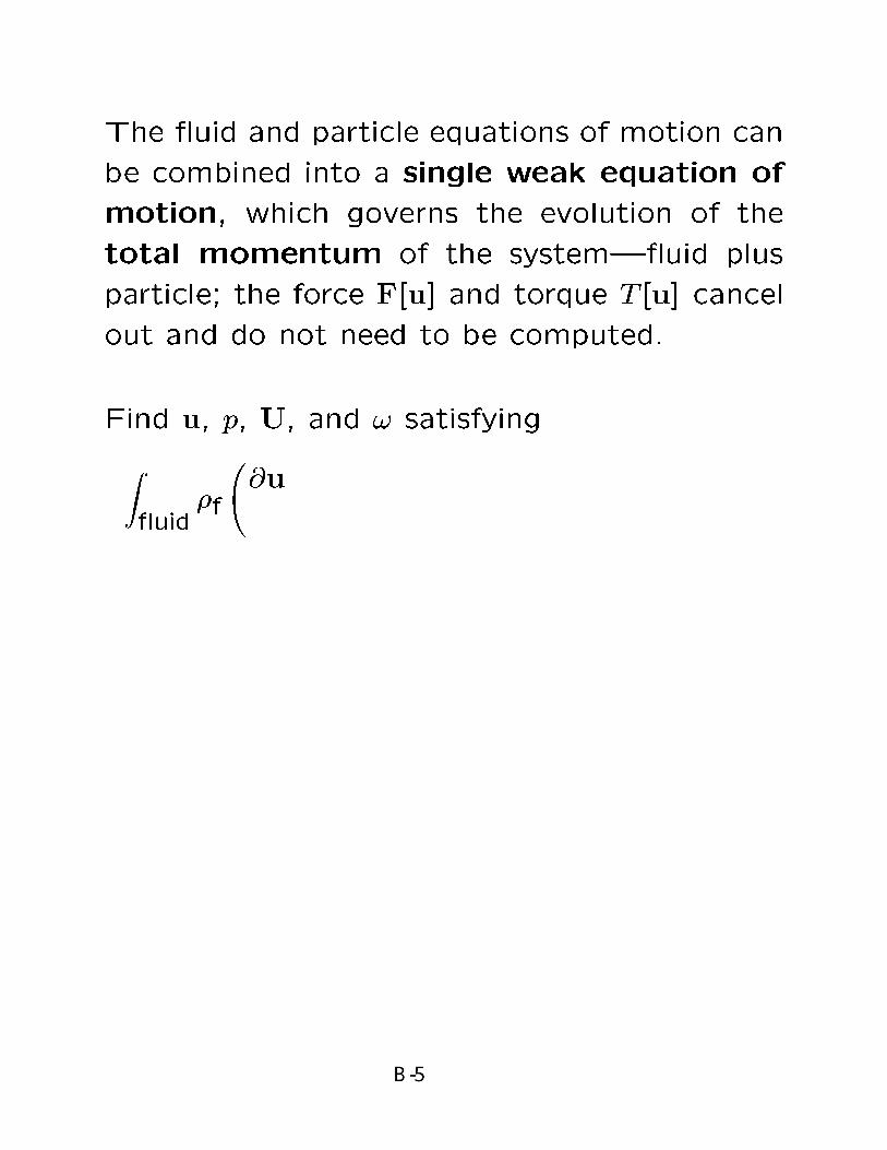
B. DIRECT NUMERICAL SIMULATION OF LIQUID- SOLID FLOW http://www.aem.umn.edu/Solid-Liquid_Flows Sponsored by NSF-Grand Challenge Grant Fluid Mechanics & CFD Computer Scientists D.D. Joseph Y. Saad R. Glowinski A. Sameh H. Hu G. Golub P. Singh A. Wathen T.W. Pan V. Sarin P.Y. Huang M. Knepley N. Patankar H.G. Choi T. Hesla M.Y. Zhu Industrial partners: Schlumberger, Dowell- Schlumberger, Shell-Houston, Stimlab, Intevep S.A. The marriage of CFD & CS is very desirable for the future of DNS but it is difficult to achieve.
The marriage of CFD & CS is very desirablefor the future of DNS but it is difficult toachieve.
METHODS FOR STUDYINGMULTIPHASE PROCESSES
• Experiments
• Analysis (mathematical models)
• Numerical simulation (computers)
Experiments and analysis are traditional methodsused for hundreds of years without the help ofbig computers. They are the basis of science andengineering.
We understand well the uses of traditionalmethods. Traditional methods are as usefultoday and into the future as they ever were.
Computers are always being used in new ways.We donÕt yet understand what the future ofcomputations may hold. The horizons are not inview; this is a good environment for visionaryresearch.
DIRECT NUMERICALSIMULATION (DNS)
Solves the dynamic problem of themotion of particles in a fluid exactly (inprinciple). The particles are moved byNewton’s laws under the action ofhydrodynamic forces computed from thenumerical solution of the fluid equations(Navier-Stokes equations for water, etc.)
Since DNS does not use approximationsit can be the STANDARD OFEXCELLENCE for approximatemethods like
DNS for turbulenceLNS Lagrangian numerical simulationLB Lattice BoltzmannMIXTURE THEORY
in which the forces on particles aremodeled rather than computed.
Approximate theories should bevalidated against DNS.
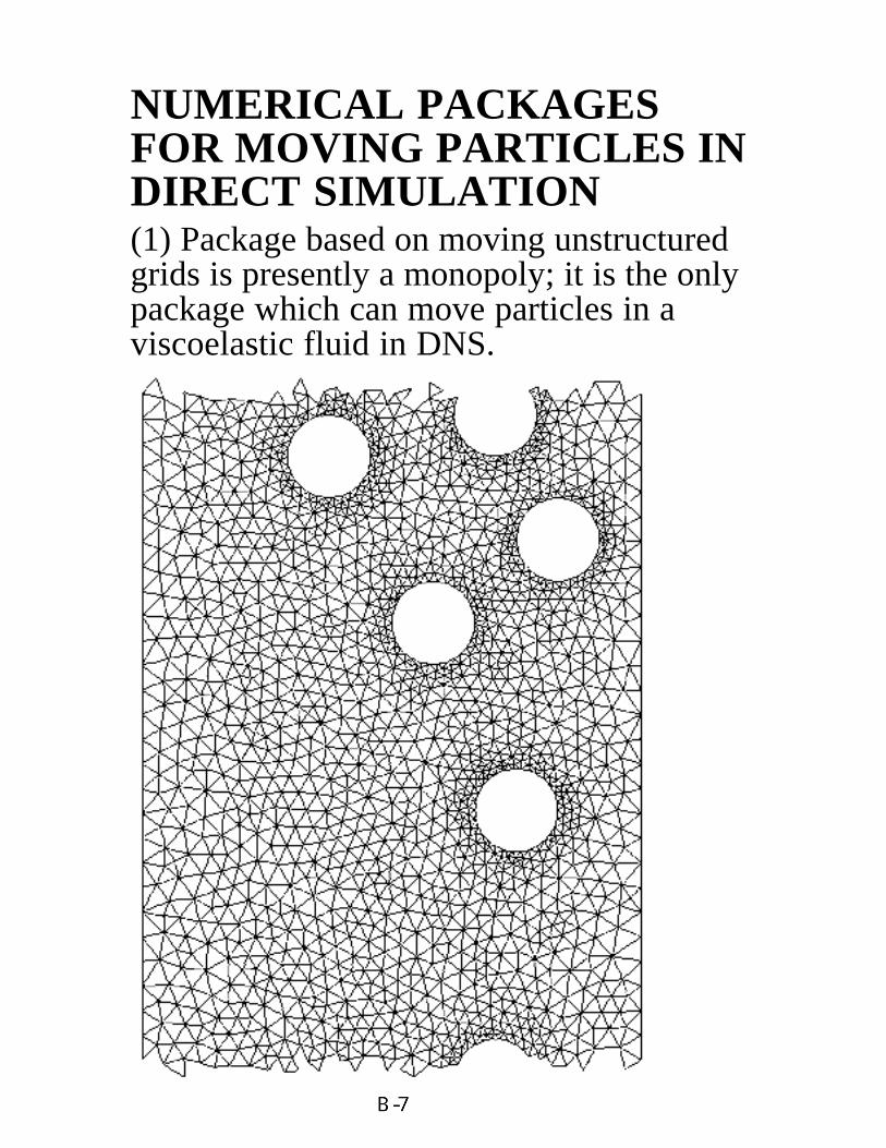
NUMERICAL PACKAGESFOR MOVING PARTICLES INDIRECT SIMULATION(1) Package based on moving unstructuredgrids is presently a monopoly; it is the onlypackage which can move particles in aviscoelastic fluid in DNS.
DLMPM: DISTRIBUTED LAGRANGE
MULTIPLIER PARTICLE MOVER
This is a brand new computational method
which allows us to use xed grids.
BASIC IDEA:
Extend uid- ow equations to the entire
uid/particle domain, both outside and in-
side the particles.
Enforce constraint of rigid-body motion in-
side the particles as a side constraint, using
distributed Lagrange multipliers.
ADVANTAGES:
Extended domain is time-independent, so
a xed mesh can be used, eliminating the
need for repeated remeshing and projec-
tion.
Extended domain is geometrically simpler,
so regular grids and fast solvers can be
used.
COMBINED WEAK FORMULATION
WITH DISTRIBUTED LAGRANGE
MULTIPLIERS ON EXTENDED
DOMAIN
Notation:
f = region occupied by uid
s = region occupied by solid
= extended domain, uid plus solid
= f [s
Find u, p, , U, and ! satisfying
Z
f
@u
@t+ u ru g
! v dx
Z
pr v dx+
Z
2D[u] :D[v] dx
+
1
f
s
!0@M dU
dt g
!V+ I
d!
dt
1A
=
Zs
v (V+ r)
dx
+
Zs
r :rv (V+ r)
dx
for all v, V, and ;
Z
qr u dx = 0 for all q;
Zs
u (U+ ! r)
dx
+
Zs
r :ru (U+ ! r)
dx = 0
for all
DLMPM EQUATIONS: STRONG FORM
Using standard methods of the calculus of vari-
ations, we obtain the following partial dieren-
tial equations of motion and constraint in f
and s. Note that the motion in s is guar-
anteed to be rigid.
Fluid (f):
f
@u
@t+ u ru
!= f g rp+ r2u;
r u= 0
Solid (s):
f
@u
@t+ u ru
!= f g rp+ r2u+ (r
2);
r u = 0;
u = U+ ! r
Boundary Condition (@s):
n [[p1+2D[u]]] = (n r);
[[]]def= ()s ()f
From the preceding equations, we can extract
the following PDE problems for u and on f
and s, given U(t) and !(t), and the positions
X and of the particles:
Fluid (f):
f
@u
@t+ u ru
!= f g rp+ r2u;
r u= 0;
u= U+ ! r on @s
Solid (s):
r2 = f
dU
dt+
d!
dt r+ ! (! r) g
!;
(n r) = n [[p1+2D[u]]] on @s
These are solvable Dirichlet problems and they
guarantee that the uid in the region s of
the extended domain occupied by solid moves
rigidly.
ADVANTAGES:
Extended domain is time-independent, so
a xed mesh can be used, eliminating the
need for repeated remeshing and projec-
tion.
Extended domain is geometrically simpler,
so regular grids and fast solvers can be
used.
APPLICATIONSOF
DNS
Y (c
m)
y
x
020406080100
02
46
810
Flui
d (n
=0.5
)Pa
rtic
les
Y (c
m)
d=1 cm
y
x
01020304050
02
46
810
Flui
d (n
=1.0
)Pa
rtic
les
Velocity Profile U (cm/s)
Y (c
m)
d=1 cm
y
x
(a) (b) (c) (d)
Velocity Profile U (cm/s) Velocity Profile U (cm/s)
0
0.1
0.2
0.3
0.4
0.5
0.6
0.7
02
46
810
Y (
cm)
d=1 cm
y
x
Flui
d (n
=0.5
)Pa
rtic
les
Velocity Profile U (cm/s)
Migration of neutrally bouyant particles in pressure driven flow by DNS.You can isolate and study effects by switching physics on and off in the simulations that you could not do in experiments. (a) Newtonian, (b) Generalized Newtonian with shear thinning index n = 0.5, (c) viscoelastic, (d) viscoelastic with shear thinning.
0
0.1
0.2
0.3
0.4
0.5
0.6
0.7
02
46
810
Flui
d (n
=1.0
)
Part
icle
s
d=1 cm
-0.1
0
0.1
0.2
0.3
0.4
0.5
0 1 2 3 4 5 6 7
U=2.0U=1.5U=1.0U=0.75U=0.5U=0.42U=0.35U=0.25
Flui
dize
d be
d H
eigh
t (H
-Ho)/
Ho
time (sec.)
(a)
(b)
SURROGATE FOR EXPERIMENTS, BEDEXPANSION OF A FLUIDIZED BED
U = 1.0 cm/s
FLUIDIZATION IN WATER OF 2411/4” PLASTIC BALLS IN A THIN 3D
BED BY DLMPM
FULLANIMATIONSON OURWEBPAGE
U = 3 cm/sec
UNDERSTANDINGMICROSTRUCTURE
There is a microstructure which is induced by the fluid dynamicsof falling bodies and is governed by very simple principles. Longbodies are stable across the stream in Newtonian fluids, but alongthe stream in non-Newtonian fluids. Spherical particles form ar-rays across the stream in Newtonian fluids and along the stream innon-Newtonian fluids.
The Mechanisms which determine the microstructure of fallingsphereical bodies are wakes and, surprisingly, the turning coupleson long bodies, like cylinders or flat plates.
The pressures in a Newtonian fluid are greatest near a stagnationpoint on the body where the flow is slow.
There are pressure in a non-Newtonian fluid due to normalstresses, which don’t exist in Newtonian fluids, and these pres-sures are greatest at points on the body where the flow is fast.
The flow microstructures which develop in Newtonian and non-Newtonian fluids are maximally different because the underlyingpressures which act on the body are greatest at opposite places onthe body.
Cylinders falling in a Newtonianfluid turn their long axis perpen-dicular to the fall. An airplane willstall or a sailing ship will turn itsbroadside across the wind if notcontrolled.
Cylinders falling in a Viscoelasticfluid turn their long axis parallelto the flow, the exact opposite of aNewtonian fluid. An airship in aviscoelastic fluid would not stalland it would not fly.
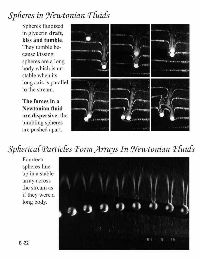
Spheres fluidizedin glycerin draft,kiss and tumble.They tumble be-cause kissingspheres are a longbody which is un-stable when itslong axis is parallelto the stream.
The forces in aNewtonian fluidare dispersive; thetumbling spheresare pushed apart.
Spheres in Newtonian Fluids
Fourteenspheres lineup in a stablearray acrossthe stream asif they were along body.
Spherical Particles Form Arrays In Newtonian Fluids
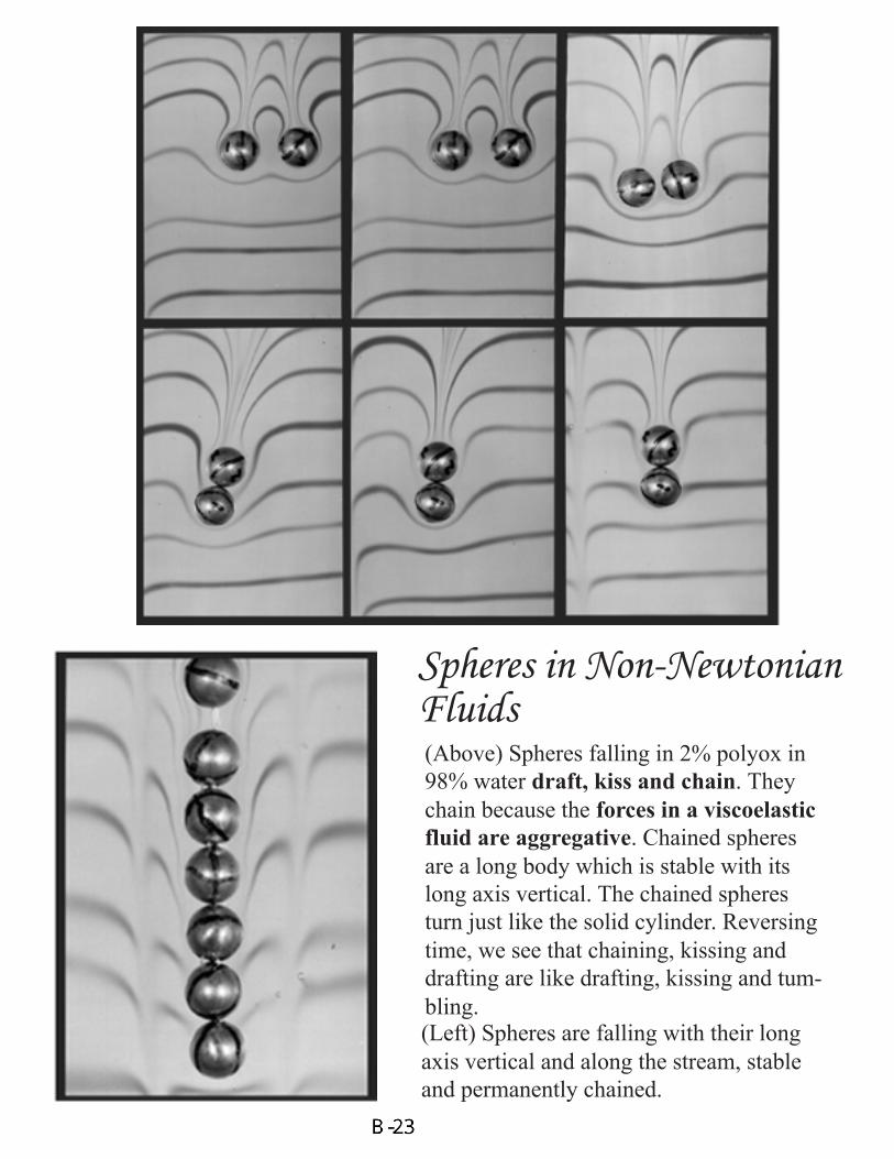
(Above) Spheres falling in 2% polyox in98% water draft, kiss and chain. Theychain because the forces in a viscoelasticfluid are aggregative. Chained spheresare a long body which is stable with itslong axis vertical. The chained spheresturn just like the solid cylinder. Reversingtime, we see that chaining, kissing anddrafting are like drafting, kissing and tum-bling.(Left) Spheres are falling with their longaxis vertical and along the stream, stableand permanently chained.
Spheres in Non-NewtonianFluids
Spherical Particles in NewtonianFluids Form Like Birds in Flight
When 22<Re<43, the spheres do not draft, kissand tumble. Three and four of them form a per-manent nested wake structure in which eachsuccessive sphere is nested in the wake of theone before and it rotates in a shear field there.This reminds us of the formation of birds inflight.
FLUIDIZED RAFT PERPENDICULAR TO U
g
A raft was constructed by gluing long cylinders. It turnsbroadside on and collects particles in its wake, like debrisbehind a truck.
(a) (b)
(c)
(d) (e)
DOUBLET TRIPLET 1
TRIPLET 2
QUADRUPLET 1 QUADRUPLET 2
Stable doublets, triplets and quadruplets.Long bodies float broadside on in a slitfluidized bed. They generate strong wakes. Ifseveral long bodies are present, they interactto form stable wake architecture: these stablestructures are permanent and nearly steady.
TWO PHASE FLOW MODELS(MIXTURE THEORY, LNS) DONOT PREDICT:
• Long bodies stable broad side on• Drafting, Kissing, and Tumbling• Across the stream arrays of spheres• Nested wake structure, ÒFlying
BirdsÓ• Doublets, Triplets, Quadruplets• Fluidized Raft, Wake Aggregates
TWO PHASE FLOW MODELSFOR VISCOELASTIC FLUIDSESSENTIALLY DO NOT EXIST
We get ideas and test ideas aboutmodeling the interaction of forcesneeded for LNS and mixture theoriesfrom DNS.
DIR
EC
T S
IMU
LAT
ION
IN 3
D L
EA
DS
TO
PLA
NE
S O
F S
PH
ER
ES
AC
RO
SS
TH
E S
TR
EA
M
Pla
nes
of fa
lling
sph
eres
acr
oss
the
stre
am in
a tu
be c
ompu
ted
by th
e A
LEpa
rtic
le m
over
. (a)
Fiv
e sp
here
s (
Re
= 4
5); f
our
are
in a
hor
izon
tal p
lane
.T
he c
ente
r sp
here
osc
illat
es o
n th
e ce
nter
line
rel
ativ
e to
the
plan
e. (
b) S
ix-
teen
sph
eres
(Re
= 2
0) in
two
rings
in a
pla
ne a
cros
s th
e flo
w.
SAND TRANSPORT IN FRACTUREDRESERVOIRS
In a slot problem a particle laden (say 20% solids) fluid is driven by apressure gradient and the particles settle to the bottom as they are draggedforward. Sand deposits on the bottom of the slot; a mound of sand devel-ops and grows until the gap between the top of the slot and the mound ofsand reaches an equilibrium value; this value is associated with a criticalvelocity. The physical processes here are settling and washout.Washoutcould be by sliding and slipping; however, a more efficient transportmechanism is by advection after resuspension which we studied by directsimulation.
Microstructural properties important for advection afterresuspension include:
• Lift-off• Lift force minus weight• Equilibrium height• Slip velocities
0.5
0.55
0.6
0.65
0.7
0.75
0.8
0 10 20 30 40 50 60
Lift off and equilibrium height as a functionof Reynolds number. The resuspended
particle does not rise much.
Density ratio = 1.01
Density ratio = 1.4
= ˙ γ wd2 ν
Wall
Particle
dd/2
he = 1
gravity
x
y
he (
cm)
Re
W/d = 12
Lift off at Re = 25
Lift off at Re = 2.83
V -V = ∆V f (c)
Ωγ
SLIP VELOCITY OFA PARTICLE
Velocity profilewithout particle
he
Vp V
p
(V , V ) = particle velocity, fluid velocityV -V = slip velocityp f
f pγ2
- Ω = angular slip velocityp
Richardson-Zaki correlations
f
p ofSlip velocityfor a singleparticle
function of theconcentration ofsolids
∆V and f (c) can be determined by experimentsor DNS
0
0.2
0.4
0.6
0.8
1
0 10 20 30 40 50 60
Slip velocity coefficient vs. Reynolds number.The slip velocity decreases after lift off.
Density ratio = 1.01
Density ratio = 1.4
=˙ γ wd2
ν
1−V
pV
f
W/d = 12
Re
Lift off
0
0.2
0.4
0.6
0.8
1
0 10 20 30 40 50 60
Fraction of lift due to pressure
Density ratio = 1.01
Density ratio = 1.4
Φp
Φs
Φp = Lp Lp + Ls
Φs = Ls Lp +Ls
= ˙ γ wd2 ν
Lif
t fr
acti
on
Re
and due to shear when W/d = 12. The lift due to pressure dominates, more strongly forheavy particles.
Lift 0ff
LIMITATIONS OF DNSThese simulations complement and competewith experiments. Experiments tell the truthin all detail. The simulations, thoughpotentially exact, have limitations of variouskinds.
• Number of particles. Simulations of flowsof hundreds of spheres in 2D andthousands in 3D have been achieved. Weare hoping to move 100,000 particles in2D and thousands in 3D
• Collisions. It is not possible to simulatethe motion of even a moderately densesuspension of particles without a strategyto handle cases in which particles touch.Four strategies have been proposed andthey work but they keep the particlesfarther apart than they ought to be,resulting in too high void fraction. Anoptimal strategy for collisions is animportant and difficult challenge for DNS.
• Turbulence. No one has yet figuredout how to do DNS when particles arein the fluid.
• Viscoelastic fluids. Even withoutparticles these simulations canÕt becarried out at the high Weissenbergnumbers frequently encountered inapplications.
SINCE THE HORIZONS FORDNS OF MULTIPHASE FLOWARE NOT IN VIEW, WE CANSTRIVE TO ELIMINATE THESELIMITATIONS ONE BY ONE.