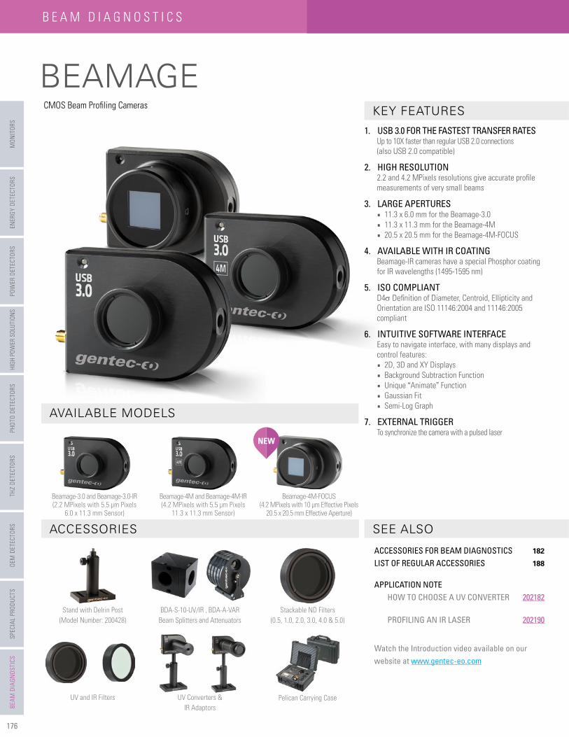
176 BEAMAGE SPECIAL PRODUCTS OEM DETECTORS THZ DETECTORS PHOTO DETECTORS HIGH POWER SOLUTIONS POWER DETECTORS ENERGY DETECTORS MONITORS BEAM DIAGNOSTICS BEAM DIAGNOSTICS Stackable ND Filters (0.5, 1.0, 2.0, 3.0, 4.0 & 5.0) Pelican Carrying Case UV Converters & IR Adaptors UV and IR Filters BDA-S-10-UV/IR , BDA-A-VAR Beam Splitters and Attenuators Stand with Delrin Post (Model Number: 200428) AVAILABLE MODELS ACCESSORIES SEE ALSO KEY FEATURES 1. USB 3.0 FOR THE FASTEST TRANSFER RATES Up to 10X faster than regular USB 2.0 connections (also USB 2.0 compatible) 2. HIGH RESOLUTION 2.2 and 4.2 MPixels resolutions give accurate profile measurements of very small beams 3. LARGE APERTURES 11.3 x 6.0 mm for the Beamage-3.0 11.3 x 11.3 mm for the Beamage-4M 20.5 x 20.5 mm for the Beamage-4M-FOCUS 4. AVAILABLE WITH IR COATING Beamage-IR cameras have a special Phosphor coating for IR wavelengths (1495-1595 nm) 5. ISO COMPLIANT D4σ Definition of Diameter, Centroid, Ellipticity and Orientation are ISO 11146:2004 and 11146:2005 compliant 6. INTUITIVE SOFTWARE INTERFACE Easy to navigate interface, with many displays and control features: 2D, 3D and XY Displays Background Subtraction Function Unique “Animate” Function Gaussian Fit Semi-Log Graph 7. EXTERNAL TRIGGER To synchronize the camera with a pulsed laser CMOS Beam Profiling Cameras Beamage-3.0 and Beamage-3.0-IR (2.2 MPixels with 5.5 μm Pixels 6.0 x 11.3 mm Sensor) Beamage-4M and Beamage-4M-IR (4.2 MPixels with 5.5 μm Pixels 11.3 x 11.3 mm Sensor) Beamage-4M-FOCUS (4.2 MPixels with 10 μm Effective Pixels 20.5 x 20.5 mm Effective Aperture) NEW ACCESSORIES FOR BEAM DIAGNOSTICS 182 LIST OF REGULAR ACCESSORIES 188 APPLICATION NOTE HOW TO CHOOSE A UV CONVERTER 202182 PROFILING AN IR LASER 202190 Watch the Introduction video available on our website at www.gentec-eo.com
Home, Setup and Acquisition Tabs:Set your capture parameters and get the resulting measures
INTUITIVE SOFTWARE INTERFACE
MAIN CONTROLSThe upper part of the software includes all the main controls in a ribbon format. These controls are grouped by family: Capture Controls, File Controls, Buffer Controls, M2 Controls and Data Computations. The last includes very useful fi lters and a normalizing function.
DISPLAYS The left-hand side of the software is the display panel. Four displays are available: 3D, 2D, XY (cross-sectional graphs along the crosshairs) and Beam Tracking. The desired display is selected by clicking on the corresponding icon at the bottom of the panel. Print screen controls are available for the 3D, 2D and Beam Tracking displays. They allow the user to save an image of the current view in BMP format.
HOME AND SETUP TABS The right-hand side of the software contains the Home, Setup and Data Acquisition tabs. The Home tab allows the user to select the main controls for his measurements (Beam Diameter Defi nition, Crosshair Center and Orientation) and displays the resulting measurements below. The Setup tab allows the user to set the measurement parameters (Exposure Time, Image Orientation and Averaging, Active Area, etc.) and the Data Acquisition tab allows the user to save measurements or measurements and full images, to enter the Sampling Rates and a Total Duration for the Acquisition. More tabs with advanced controls are available when clicking on the Show/Hide Options button in the Computations panel.
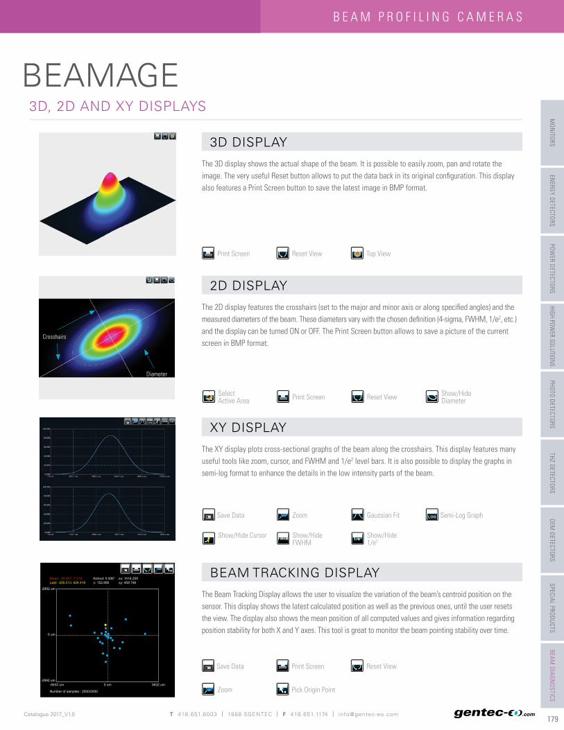
The 3D display shows the actual shape of the beam. It is possible to easily zoom, pan and rotate the image. The very useful Reset button allows to put the data back in its original confi guration. This display also features a Print Screen button to save the latest image in BMP format.
The 2D display features the crosshairs (set to the major and minor axis or along specifi ed angles) and the measured diameters of the beam. These diameters vary with the chosen defi nition (4-sigma, FWHM, 1/e2, etc.) and the display can be turned ON or OFF. The Print Screen button allows to save a picture of the current screen in BMP format.
The XY display plots cross-sectional graphs of the beam along the crosshairs. This display features many useful tools like zoom, cursor, and FWHM and 1/e2 level bars. It is also possible to display the graphs in semi-log format to enhance the details in the low intensity parts of the beam.
The Beam Tracking Display allows the user to visualize the variation of the beam’s centroid position on the sensor. This display shows the latest calculated position as well as the previous ones, until the user resets the view. The display also shows the mean position of all computed values and gives information regarding position stability for both X and Y axes. This tool is great to monitor the beam pointing stability over time.
Filter out the noise in your beam profi le by using one of the fi lter functions. The Beamage has both smoothing and despeckle fi lters. The Smoothing fi lter is a soft noise reduction method whereas the Despeckle fi lter is a much more aggressive spatial fi lter that is designed to remove speckles and noisy signals from very poor quality beam profi les. Instead of performing a 3x3 pixel smoothing fi lter with a relative weight of 20% for the central pixel and 10% for the others, the software performs a 9x9 pixels simple averaging, with all pixels having the same relative weight (1/81). The fi lter can be found in the Filters menu of the main controls.
ON
OFF
DIVERGENCE
The Divergence of a beam is defi ned as the increase in beam radius with propagation from the optical aperture. For most applications, a lower-divergence beam is preferable. Using the new Divergence tab in the PC-Beamage application, this parameter can now be computed for both mains axes (X, Y) according to the ISO 11146-1:2005 and 11146-2:2005 standards. A focal lens with a known focal lenght is required for the measurement of the divergence.
ACQUISITION
In the Acquisition tab, the user can defi ne a total duration for the acquisition and can specify a name and a path for his saved fi les. The user can either choose to save measurements only or both measurements and full images. It is possible to save the data shown in the measure tab in a *TXT fi le, which includes a header that displays the custom acquisition settings above the data. Each line corresponds to a single frame. This fi le can be opened in a spreadsheet software such as Microsoft Excel. It is also possible to save the images associated with the measurements from the *.TXT logging fi le. Each image will be individually saved in a native *.BMG fi le. For measurements, it is possible to choose a sampling rate for the saved data. Similarly, for the full images, one can manually set a temporal interval at which the software will save the data. With these tools, the user will be able to store only the information that is useful to his work.
RELATIVE POSITION
In the “Relative Position” tab, the “Setup” section allows the user to select the parameter that will be considered as the origin position (0,0). “Centroid” (center of energy) and “Peak” (highest measured value) are the options. The “User Defi ne” option allows the user to manually enter origin position values for both axes. It is also possible to position the origin by simply clicking with the mouse in the display. Once the origin position is determined by the user, the software calculates the difference between the coordinates of this new position and the latest computed one. The results are displayed in the “Measures” section. It is possible to save the data in the acquisition fi le if desired.
MAIN FUNCTIONS
Divergence (Θ)
FocalLength (l)
CMOSSensor
FocusingLens
DivergentLaser Source
Actual focus shouldfall behind camera face
181
BEAMAGE
Catalogue 2017_V1.0 .com
SPECIAL PRODUCTSOEM
DETECTORS THZ DETECTORS
PHOTO DETECTORSHIGH POW
ER SOLUTIONS POW
ER DETECTORSENERGY DETECTORS
MONITORS
BEAM DIAGNOSTICS
OFF ON
ACTIVE AREA (ROI)Increase the data transfer rate by reducing the area of the sensor that is scanned. This tool is perfect for small beams that don’t need the full sensor area.
PIXEL ADDRESSINGIncrease the data tranfer rate by using larger pixels or by reducing the number of pixels. This is great for large beams that don’t need the full resolution.
SUBTRACT BACKGROUNDThe background subtraction function is a necessary tool to have an accurate measurement and to abide by the ISO 11146-3:2004 standards. By taking 10 images and averaging them pixel by pixel to compute the average background map, contamination of all images can be avoided with the help of environment noise subtraction.
ANIMATEGive life to your measures with the animate function. With as much as 32 images temporarily saved in the buffer, simply pressing the animation button will create a movie with any display (2D, 3D and XY). This allows to visualize the beam while working offl ine and to have a recalculation process if the beam diameter defi nition or crosshair parameters are changed.
MULTIPLE CAMERASIt is possible to use multiple Beamage cameras on one computer simultaneously. By running multiple PC-Beamage instances and selecting the desired camera for each one, the user will be able to stream multiple cameras simultaneously, thus effectively monitoring all the beams and easily switching from one to another.
NORMALIZEThe normalize function spreads the intensity over the full range (0% to 100%). This is especially useful with low level signals or to enhance the variations in the beam.
TRIGGERFor the case of pulsed laser sources, the trigger function will be useful to synchronize the system’s capture rate with the source’s repetition rate, especially when this one is low (<16 Hz). To be achieved, a TTL (0-5 V) or other (1.1-24 V) trigger signal can be connected to the Beamage camera via a BNC or SMA plug.
IMAGE AVERAGINGThe image averaging function uses a temporal fi lter that captures 2, 5 or as much as 10 images of the beam to create a single time-averaged image with them. This process will smooth the beam fl uctuations that can occur over time when working with unstable laser sources.