31
(1) SINGHANIA UNIVERSITY, PACHERI BARI, JHUNJHUNU, RAJASTHAN. 1. B.Tech. Instrumentation & Control Engineering
(1)
SINGHANIA UNIVERSITY,PACHERI BARI, JHUNJHUNU, RAJASTHAN.
1. B.Tech. Instrumentation & Control Engineering

(2)
SINGHANIA UNIVERSITYStudy and Evaluation Scheme
B.Tech. Instrumentation & Control Engineering,
YEAR 2nd, SEMESTER-III
S. No. CourseCode
SUBJECT PERIODSEvaluation Scheme
SubjectTotal C
redi
t
SESSIONALEXAM. ESE
L T P CT TA TotalTHEORY SUBJECTS1. EHU-301/
EHU-302Industrial Psychology/Industrial Sociology
2 0 0 15 10 25 50 75 2
2. EAS-301/EOE-031-EOE-038
Mathematics III/ Sciencebased open Elective**
3 1 0 30 20 50 100 150 4
3. EEC-301 Fundamentals of ElectronicsDevices
3 1 0 30 20 50 100 150 4
4. EEC-302 Digital Electronics 3 1 0 30 20 50 100 150 45. EEC-303 Electromagnetic Field Theory 3 1 0 30 20 50 100 150 46. EEC-304 Fundamentals of Network
Analysis & Synthesis3 1 0 30 20 50 100 150 4
7. EHU-111 *Human Values &Professional Ethics
2 2 0 15 10 25 50 75 -
PRACTICAL/DESIGN/DRAWING8 EEC-351 Electronics Engineering Lab I 0 0 2 -- 20 20 30 50 1
9. EEC-352 Digital Electronics Lab-I 0 0 2 -- 20 20 30 50 110. EEC-353 PCB & Electronics Workshop 0 0 2 -- 10 10 15 25 111. GP 301 General Proficiency - - - - - 50 - 50 1
Total 17 5 6 165 160 375 625 1000 26
* Human Values & Professional Ethics will be offered as compulsory Audit Course for which passing marks are40% in theory & 50% in aggregate. Students will be required to audit it within the period of their study. Therewill not be carry over facility for this course and a failure student will be required to repeat this course.
Note : Numbers of departmental subjects/labs in any semester may vary as per requirement keeping subject total andcredit total unchanged.
** Science based open ElectiveEOE031/EOE041 Introduction to soft computing (Neural network, Fuzzy logic and Genetic algorithm)EOE032/EOE042 Nano-sciencesEOE033/EOE043 Laser systems and applicationsEOE034/EOE044 Space sciencesEOE035/EOE045 Polymer science and technologyEOE036/EOE046 Nuclear scienceEOE037/EOE047 Material scienceEOE038/EOE048 Discrete mathematics
(3)
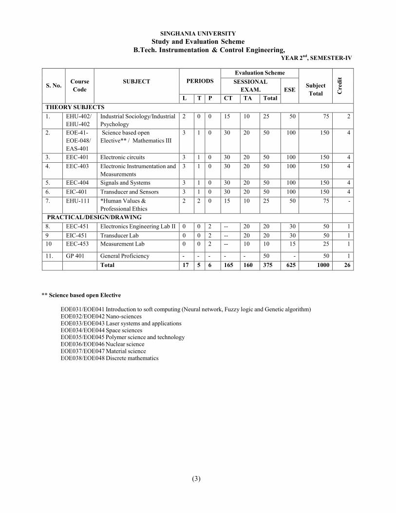
SINGHANIA UNIVERSITYStudy and Evaluation Scheme
B.Tech. Instrumentation & Control Engineering,YEAR 2nd, SEMESTER-IV
S. No. CourseCode
SUBJECT PERIODSEvaluation Scheme
SubjectTotal C
redi
t
SESSIONALEXAM. ESE
L T P CT TA TotalTHEORY SUBJECTS1. EHU-402/
EHU-402Industrial Sociology/IndustrialPsychology
2 0 0 15 10 25 50 75 2
2. EOE-41-EOE-048/EAS-401
Science based openElective** / Mathematics III
3 1 0 30 20 50 100 150 4
3. EEC-401 Electronic circuits 3 1 0 30 20 50 100 150 44. EEC-403 Electronic Instrumentation and
Measurements3 1 0 30 20 50 100 150 4
5. EEC-404 Signals and Systems 3 1 0 30 20 50 100 150 46. EIC-401 Transducer and Sensors 3 1 0 30 20 50 100 150 47. EHU-111 *Human Values &
Professional Ethics2 2 0 15 10 25 50 75 -
PRACTICAL/DESIGN/DRAWING8. EEC-451 Electronics Engineering Lab II 0 0 2 -- 20 20 30 50 19 EIC-451 Transducer Lab 0 0 2 -- 20 20 30 50 110 EEC-453 Measurement Lab 0 0 2 -- 10 10 15 25 1
11. GP 401 General Proficiency - - - - - 50 - 50 1Total 17 5 6 165 160 375 625 1000 26
** Science based open Elective
EOE031/EOE041 Introduction to soft computing (Neural network, Fuzzy logic and Genetic algorithm)EOE032/EOE042 Nano-sciencesEOE033/EOE043 Laser systems and applicationsEOE034/EOE044 Space sciencesEOE035/EOE045 Polymer science and technologyEOE036/EOE046 Nuclear scienceEOE037/EOE047 Material scienceEOE038/EOE048 Discrete mathematics
(4)
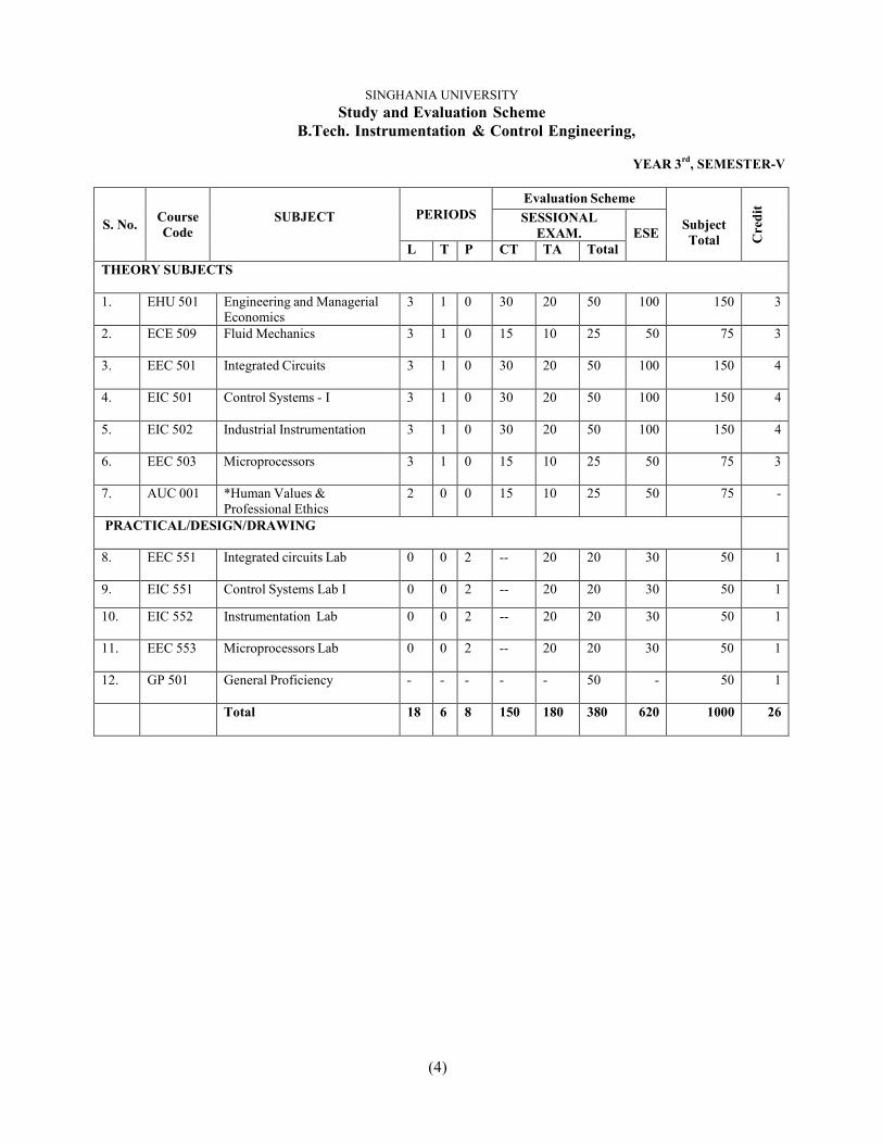
SINGHANIA UNIVERSITYStudy and Evaluation Scheme
B.Tech. Instrumentation & Control Engineering,
YEAR 3rd, SEMESTER-V
S. No. CourseCode
SUBJECT PERIODSEvaluation Scheme
SubjectTotal C
redi
t
SESSIONALEXAM. ESE
L T P CT TA TotalTHEORY SUBJECTS
1. EHU 501 Engineering and ManagerialEconomics
3 1 0 30 20 50 100 150 3
2. ECE 509 Fluid Mechanics 3 1 0 15 10 25 50 75 3
3. EEC 501 Integrated Circuits 3 1 0 30 20 50 100 150 4
4. EIC 501 Control Systems - I 3 1 0 30 20 50 100 150 4
5. EIC 502 Industrial Instrumentation 3 1 0 30 20 50 100 150 4
6. EEC 503 Microprocessors 3 1 0 15 10 25 50 75 3
7. AUC 001 *Human Values &Professional Ethics
2 0 0 15 10 25 50 75 -
PRACTICAL/DESIGN/DRAWING
8. EEC 551 Integrated circuits Lab 0 0 2 -- 20 20 30 50 1
9. EIC 551 Control Systems Lab I 0 0 2 -- 20 20 30 50 1
10. EIC 552 Instrumentation Lab 0 0 2 -- 20 20 30 50 1
11. EEC 553 Microprocessors Lab 0 0 2 -- 20 20 30 50 1
12. GP 501 General Proficiency - - - - - 50 - 50 1
Total 18 6 8 150 180 380 620 1000 26
(5)
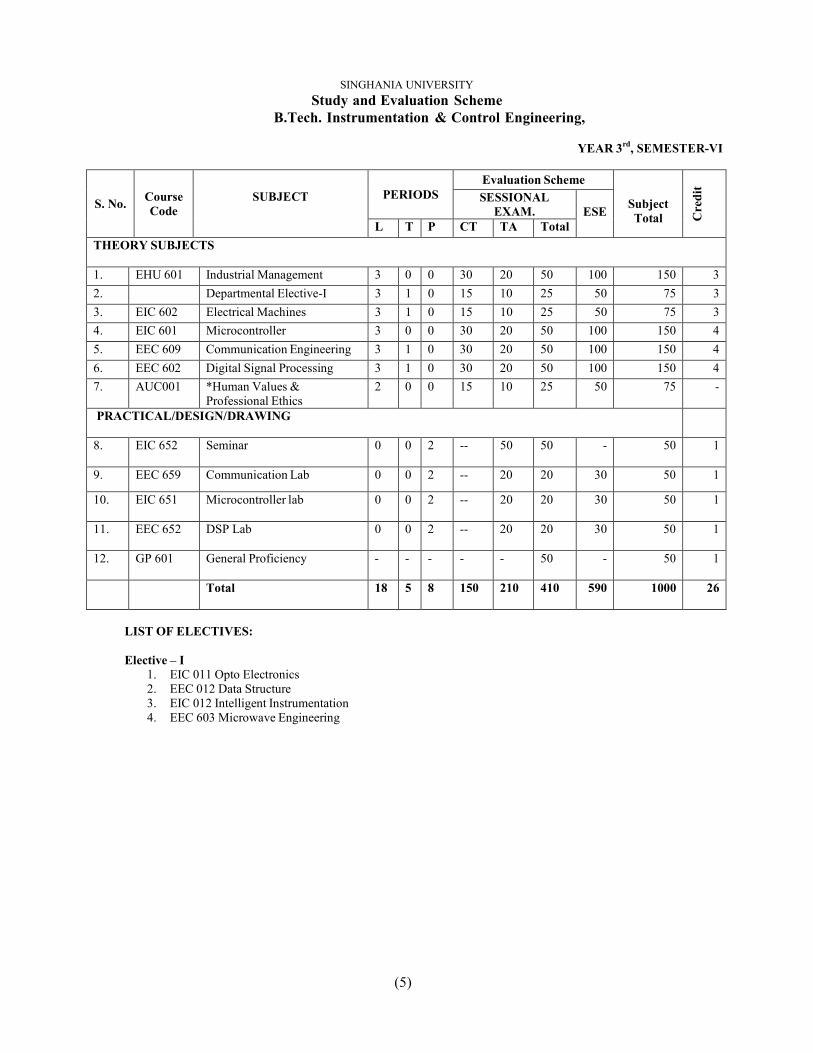
SINGHANIA UNIVERSITYStudy and Evaluation Scheme
B.Tech. Instrumentation & Control Engineering,
YEAR 3rd, SEMESTER-VI
S. No. CourseCode
SUBJECT PERIODSEvaluation Scheme
SubjectTotal C
redi
t
SESSIONALEXAM. ESE
L T P CT TA TotalTHEORY SUBJECTS
1. EHU 601 Industrial Management 3 0 0 30 20 50 100 150 32. Departmental Elective-I 3 1 0 15 10 25 50 75 33. EIC 602 Electrical Machines 3 1 0 15 10 25 50 75 34. EIC 601 Microcontroller 3 0 0 30 20 50 100 150 45. EEC 609 Communication Engineering 3 1 0 30 20 50 100 150 46. EEC 602 Digital Signal Processing 3 1 0 30 20 50 100 150 47. AUC001 *Human Values &
Professional Ethics2 0 0 15 10 25 50 75 -
PRACTICAL/DESIGN/DRAWING
8. EIC 652 Seminar 0 0 2 -- 50 50 - 50 1
9. EEC 659 Communication Lab 0 0 2 -- 20 20 30 50 1
10. EIC 651 Microcontroller lab 0 0 2 -- 20 20 30 50 1
11. EEC 652 DSP Lab 0 0 2 -- 20 20 30 50 1
12. GP 601 General Proficiency - - - - - 50 - 50 1
Total 18 5 8 150 210 410 590 1000 26
LIST OF ELECTIVES:
Elective – I1. EIC 011 Opto Electronics2. EEC 012 Data Structure3. EIC 012 Intelligent Instrumentation4. EEC 603 Microwave Engineering
(6)
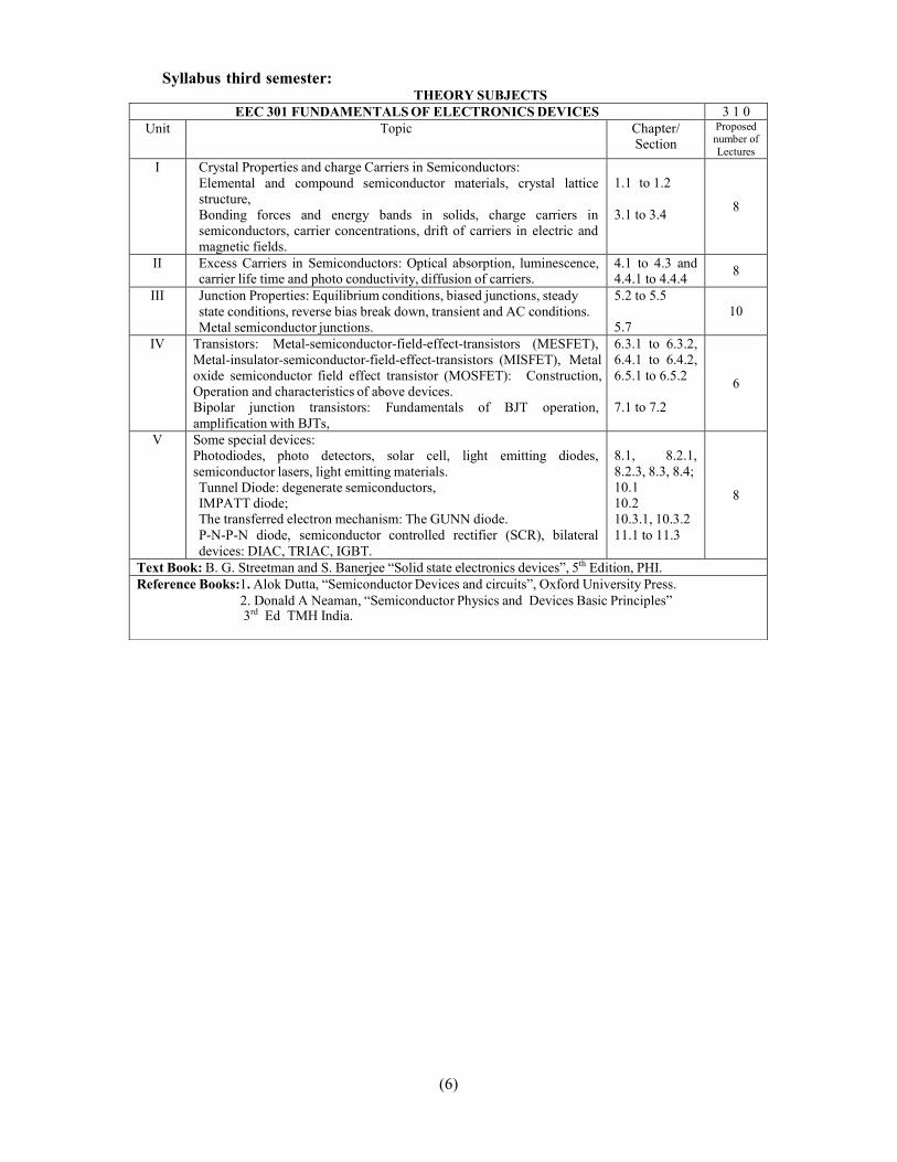
EEC 301 FUNDAMENTALS OF ELECTRONICS DEVICES 3 1 0Unit Topic Chapter/
SectionProposednumber ofLectures
I Crystal Properties and charge Carriers in Semiconductors:Elemental and compound semiconductor materials, crystal latticestructure,Bonding forces and energy bands in solids, charge carriers insemiconductors, carrier concentrations, drift of carriers in electric andmagnetic fields.
1.1 to 1.2
3.1 to 3.4 8
II Excess Carriers in Semiconductors: Optical absorption, luminescence,carrier life time and photo conductivity, diffusion of carriers.
4.1 to 4.3 and4.4.1 to 4.4.4 8
III Junction Properties: Equilibrium conditions, biased junctions, steadystate conditions, reverse bias break down, transient and AC conditions.Metal semiconductor junctions.
5.2 to 5.5
5.710
IV Transistors: Metal-semiconductor-field-effect-transistors (MESFET),Metal-insulator-semiconductor-field-effect-transistors (MISFET), Metaloxide semiconductor field effect transistor (MOSFET): Construction,Operation and characteristics of above devices.Bipolar junction transistors: Fundamentals of BJT operation,amplification with BJTs,
6.3.1 to 6.3.2,6.4.1 to 6.4.2,6.5.1 to 6.5.2
7.1 to 7.2
6
V Some special devices:Photodiodes, photo detectors, solar cell, light emitting diodes,semiconductor lasers, light emitting materials.Tunnel Diode: degenerate semiconductors,IMPATT diode;The transferred electron mechanism: The GUNN diode.P-N-P-N diode, semiconductor controlled rectifier (SCR), bilateraldevices: DIAC, TRIAC, IGBT.
8.1, 8.2.1,8.2.3, 8.3, 8.4;10.110.210.3.1, 10.3.211.1 to 11.3
8
Text Book: B. G. Streetman and S. Banerjee “Solid state electronics devices”, 5th Edition, PHI.Reference Books:1. Alok Dutta, “Semiconductor Devices and circuits”, Oxford University Press.
2. Donald A Neaman, “Semiconductor Physics and Devices Basic Principles”3rd Ed TMH India.
Syllabus third semester:THEORY SUBJECTS
(7)
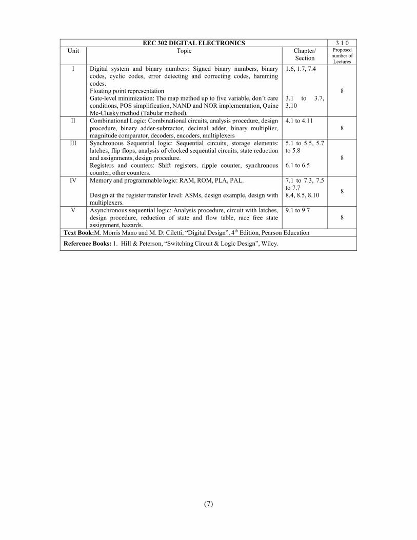
EEC 302 DIGITAL ELECTRONICS 3 1 0Unit Topic Chapter/
SectionProposednumber ofLectures
I Digital system and binary numbers: Signed binary numbers, binarycodes, cyclic codes, error detecting and correcting codes, hammingcodes.Floating point representationGate-level minimization: The map method up to five variable, don’t careconditions, POS simplification, NAND and NOR implementation, QuineMc-Clusky method (Tabular method).
1.6, 1.7, 7.4
3.1 to 3.7,3.10
8
II Combinational Logic: Combinational circuits, analysis procedure, designprocedure, binary adder-subtractor, decimal adder, binary multiplier,magnitude comparator, decoders, encoders, multiplexers
4.1 to 4.118
III Synchronous Sequential logic: Sequential circuits, storage elements:latches, flip flops, analysis of clocked sequential circuits, state reductionand assignments, design procedure.Registers and counters: Shift registers, ripple counter, synchronouscounter, other counters.
5.1 to 5.5, 5.7to 5.8
6.1 to 6.58
IV Memory and programmable logic: RAM, ROM, PLA, PAL.
Design at the register transfer level: ASMs, design example, design withmultiplexers.
7.1 to 7.3, 7.5to 7.78.4, 8.5, 8.10 8
V Asynchronous sequential logic: Analysis procedure, circuit with latches,design procedure, reduction of state and flow table, race free stateassignment, hazards.
9.1 to 9.78
Text Book:M. Morris Mano and M. D. Ciletti, “Digital Design”, 4th Edition, Pearson Education
Reference Books: 1. Hill & Peterson, “Switching Circuit & Logic Design”, Wiley.
(8)
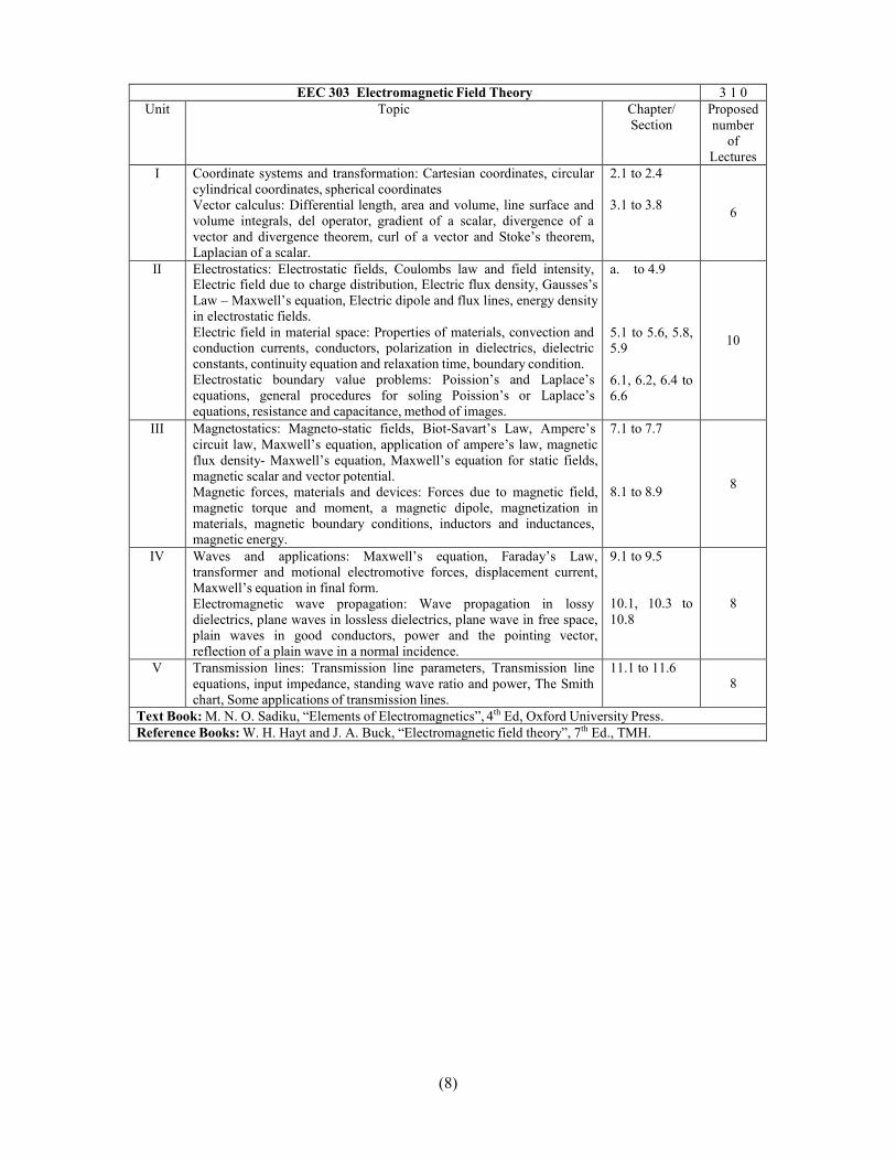
EEC 303 Electromagnetic Field Theory 3 1 0Unit Topic Chapter/
SectionProposednumber
ofLectures
I Coordinate systems and transformation: Cartesian coordinates, circularcylindrical coordinates, spherical coordinatesVector calculus: Differential length, area and volume, line surface andvolume integrals, del operator, gradient of a scalar, divergence of avector and divergence theorem, curl of a vector and Stoke’s theorem,Laplacian of a scalar.
2.1 to 2.4
3.1 to 3.8 6
II Electrostatics: Electrostatic fields, Coulombs law and field intensity,Electric field due to charge distribution, Electric flux density, Gausses’sLaw – Maxwell’s equation, Electric dipole and flux lines, energy densityin electrostatic fields.Electric field in material space: Properties of materials, convection andconduction currents, conductors, polarization in dielectrics, dielectricconstants, continuity equation and relaxation time, boundary condition.Electrostatic boundary value problems: Poission’s and Laplace’sequations, general procedures for soling Poission’s or Laplace’sequations, resistance and capacitance, method of images.
a. to 4.9
5.1 to 5.6, 5.8,5.9
6.1, 6.2, 6.4 to6.6
10
III Magnetostatics: Magneto-static fields, Biot-Savart’s Law, Ampere’scircuit law, Maxwell’s equation, application of ampere’s law, magneticflux density- Maxwell’s equation, Maxwell’s equation for static fields,magnetic scalar and vector potential.Magnetic forces, materials and devices: Forces due to magnetic field,magnetic torque and moment, a magnetic dipole, magnetization inmaterials, magnetic boundary conditions, inductors and inductances,magnetic energy.
7.1 to 7.7
8.1 to 8.9 8
IV Waves and applications: Maxwell’s equation, Faraday’s Law,transformer and motional electromotive forces, displacement current,Maxwell’s equation in final form.Electromagnetic wave propagation: Wave propagation in lossydielectrics, plane waves in lossless dielectrics, plane wave in free space,plain waves in good conductors, power and the pointing vector,reflection of a plain wave in a normal incidence.
9.1 to 9.5
10.1, 10.3 to10.8
8
V Transmission lines: Transmission line parameters, Transmission lineequations, input impedance, standing wave ratio and power, The Smithchart, Some applications of transmission lines.
11.1 to 11.68
Text Book: M. N. O. Sadiku, “Elements of Electromagnetics”, 4th Ed, Oxford University Press.Reference Books: W. H. Hayt and J. A. Buck, “Electromagnetic field theory”, 7th Ed., TMH.

(9)
EEC 304 FUNDAMENTAL OF NETWORK ANALYSIS & SYNTHESIS 3 1 0Unit Topic Chapter/
SectionProposednumber ofLectures
I Signal analysis, complex frequency, network analysis, network synthesisGeneral characteristics and descriptions of signals, step function andassociated wave forms, The unit impulseIntroduction to network analysis, network elements, initial and finalconditions, step and impulse response, solution of network equations,
1.1 to 1.42.1 to 2.3
5.1 to 5.510
II Review of Laplace transforms, poles and zeroes, initial and final valuetheorems, The transform circuit, Thevenin’s and Norton’s theorems, thesystem function, step and impulse responses, the convolution integral.Amplitude and phase responses.Network functions, relation between port parameters, transfer functionsusing two port parameters, interconnection of two ports.
7.1 to 7.5
8.19.1 to 9.4 8
III Hurwitz polynomials, positive real functions.Properties of real immittance functions, synthesis of LC driving pointimmittances, properties of RC driving point impedances, synthesis of RCimpedances or RL admittances, properties of RL impedances and RCadmittances.
10.2,10.311.1 to 11.5
8
IV Properties of transfer functions, zeroes of transmission, synthesis of Y21and Z21 with 1Ω terminations.
12.1 to 12.3 6
V Introduction to active network synthesis
Active Network Synthesis
Material availableon UPTU website&8.7 (Text Book 2)
8
Text Book:1. Franklin F. Kuo, “Network Analysis and synthesis”, 2nd Edition, Wiley India Pvt Ltd.2. Behrouz Peikari, “Fundamentals of Network Analysis & synthesis”, Jaico Publishing House, 2006.
Reference Books: M. E. Van Valkenberg, “Network Analysis”, 2nd Edition, Prentice Hall of India Ltd.

(10)
LABORATORY
EEC 351 ELECTRONICS ENGINEERING LAB IObjective: To attain expertise in lab equipment handling and understanding the basic devices, their
properties, characteristics in detail. Along with their practical usage in the circuit
1. Study of lab equipments and components: CRO, Multimeter, Function Generator, Power supply-Active, Passive Components & Bread Board.
2. P-N Junction Diode: Characteristics of PN Junction diode-Static and dynamic resistance measurementfrom graph.
3. Applications of PN junction diode: Half & Full wave rectifier- Measurement of Vrms, Vdc, andripple factor-use of filter- ripple reduction (RC Filter)-Clipper & Clamper
4. Properties of junctions Zener diode characteristics. Heavy doping alters the reverse characteristics.Graphical measurement of forward and reverse resistance.
5. Application of Zener diode: Zener diode as voltage regulator. Measurement of percentage regulationby varying load resistor.
6. Characteristic of BJT: BJT in CB and CE configuration- Graphical measurement of h parametersfrom input and output characteristics. Measurement of Av, AI, Ro and Ri of CE amplifier with potentialdivider biasing.
7. Characteristic of FET: FET in common source configuration. Graphical measurement of itsparameters gm, rd & m from input and output characteristics.
8. Characteristic of silicon-controlled rectifier.9. To plot V-I Characteristics of DIAC.10. To draw V-I characteristics of TRIAC for different values of Gate Currents.
EEC 352 DIGITAL ELECTRONICS LABObjective: To understand the digital logic and create various systems by using these logics.1. Introduction to digital electronics lab- nomenclature of digital ICs, specifications, study of the data
sheet, concept of Vcc and ground, verification of the truth tables of logic gates using TTL ICs.2. Implementation of the given Boolean function using logic gates in both SOP and POS forms.3. Verification of state tables of RS, JK, T and D flip-flops using NAND & NOR gates.4. Implementation and verification of Decoder/De-multiplexer and Encoder using logic gates.5. Implementation of 4x1 multiplexer using logic gates.6. Implementation of 4-bit parallel adder using 7483 IC.7. Design, and verify the 4-bit synchronous counter.8. Design, and verify the 4-bit asynchronous counter.9. Mini Project.
EEC 353 ELECTRONIC WORKSHOP & PCB LABObjective: To create interest in Hardware Technology.
1. Winding shop: Step down transformer winding of less than 5VA.2. Soldering shop: Fabrication of DC regulated power supply3. PCB Lab: (a) Artwork & printing of a simple PCB.
(b) Etching & drilling of PCB.4. Wiring & fitting shop: Fitting of power supply along with a meter in cabinet.5. Testing of regulated power supply fabricated.Fabricate and test the audio amplifier circuit by using above power supply
(11)
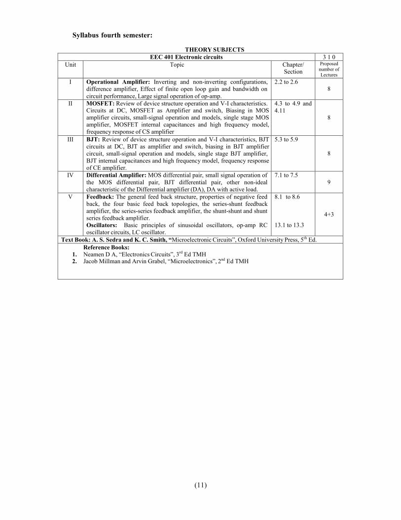
EEC 401 Electronic circuits 3 1 0Unit Topic Chapter/
SectionProposednumber ofLectures
I Operational Amplifier: Inverting and non-inverting configurations,difference amplifier, Effect of finite open loop gain and bandwidth oncircuit performance, Large signal operation of op-amp.
2.2 to 2.68
II MOSFET: Review of device structure operation and V-I characteristics.Circuits at DC, MOSFET as Amplifier and switch, Biasing in MOSamplifier circuits, small-signal operation and models, single stage MOSamplifier, MOSFET internal capacitances and high frequency model,frequency response of CS amplifier
4.3 to 4.9 and4.11
8
III BJT: Review of device structure operation and V-I characteristics, BJTcircuits at DC, BJT as amplifier and switch, biasing in BJT amplifiercircuit, small-signal operation and models, single stage BJT amplifier,BJT internal capacitances and high frequency model, frequency responseof CE amplifier.
5.3 to 5.9
8
IV Differential Amplifier: MOS differential pair, small signal operation ofthe MOS differential pair, BJT differential pair, other non-idealcharacteristic of the Differential amplifier (DA), DA with active load.
7.1 to 7.59
V Feedback: The general feed back structure, properties of negative feedback, the four basic feed back topologies, the series-shunt feedbackamplifier, the series-series feedback amplifier, the shunt-shunt and shuntseries feedback amplifier.Oscillators: Basic principles of sinusoidal oscillators, op-amp RCoscillator circuits, LC oscillator.
8.1 to 8.6
13.1 to 13.3
4+3
Text Book: A. S. Sedra and K. C. Smith, “Microelectronic Circuits”, Oxford University Press, 5th Ed.Reference Books:
1. Neamen D A, “Electronics Circuits”, 3rd Ed TMH2. Jacob Millman and Arvin Grabel, “Microelectronics”, 2nd Ed TMH
Syllabus fourth semester:
THEORY SUBJECTS
(12)
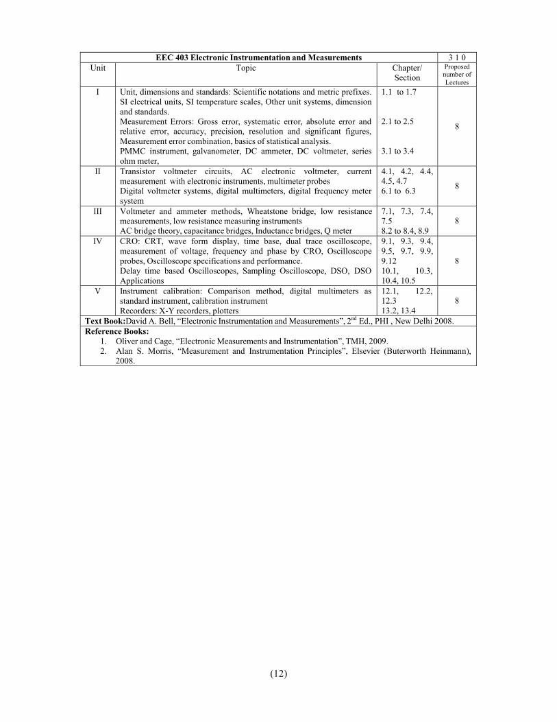
EEC 403 Electronic Instrumentation and Measurements 3 1 0Unit Topic Chapter/
SectionProposednumber ofLectures
I Unit, dimensions and standards: Scientific notations and metric prefixes.SI electrical units, SI temperature scales, Other unit systems, dimensionand standards.Measurement Errors: Gross error, systematic error, absolute error andrelative error, accuracy, precision, resolution and significant figures,Measurement error combination, basics of statistical analysis.PMMC instrument, galvanometer, DC ammeter, DC voltmeter, seriesohm meter,
1.1 to 1.7
2.1 to 2.5
3.1 to 3.4
8
II Transistor voltmeter circuits, AC electronic voltmeter, currentmeasurement with electronic instruments, multimeter probesDigital voltmeter systems, digital multimeters, digital frequency metersystem
4.1, 4.2, 4.4,4.5, 4.76.1 to 6.3 8
III Voltmeter and ammeter methods, Wheatstone bridge, low resistancemeasurements, low resistance measuring instrumentsAC bridge theory, capacitance bridges, Inductance bridges, Q meter
7.1, 7.3, 7.4,7.58.2 to 8.4, 8.9
8
IV CRO: CRT, wave form display, time base, dual trace oscilloscope,measurement of voltage, frequency and phase by CRO, Oscilloscopeprobes, Oscilloscope specifications and performance.Delay time based Oscilloscopes, Sampling Oscilloscope, DSO, DSOApplications
9.1, 9.3, 9.4,9.5, 9.7, 9.9,9.1210.1, 10.3,10.4, 10.5
8
V Instrument calibration: Comparison method, digital multimeters asstandard instrument, calibration instrumentRecorders: X-Y recorders, plotters
12.1, 12.2,12.313.2, 13.4
8
Text Book:David A. Bell, “Electronic Instrumentation and Measurements”, 2nd Ed., PHI , New Delhi 2008.Reference Books:
1. Oliver and Cage, “Electronic Measurements and Instrumentation”, TMH, 2009.2. Alan S. Morris, “Measurement and Instrumentation Principles”, Elsevier (Buterworth Heinmann),
2008.
(13)
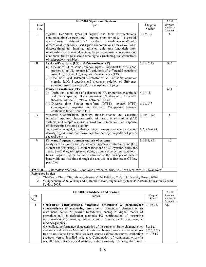
EEC 404 Signals and Systems 3 1 0UnitNo.
Topics Chapter/Section
Proposednumber ofLectures
I Signals: Definition, types of signals and their representations:continuous-time/discrete-time, periodic/non-periodic, even/odd,energy/power, deterministic/ random, one-dimensional/multi-dimensional; commonly used signals (in continuous-time as well as indiscrete-time): unit impulse, unit step, unit ramp (and their inter-relationships), exponential, rectangular pulse, sinusoidal; operations oncontinuous-time and discrete-time signals (including transformationsof independent variables).
1.1 to 1.5 6
II Laplace-Transform (LT) and Z-transform (ZT):(i) One-sided LT of some common signals, important theorems and
properties of LT, inverse LT, solutions of differential equationsusing LT, Bilateral LT, Regions of convergence (ROC)
(ii) One sided and Bilateral Z-transforms, ZT of some commonsignals, ROC, Properties and theorems, solution of differenceequations using one-sided ZT, s- to z-plane mapping
2.1 to 2.15 3+5
III Fourier Transforms (FT):(i) Definition, conditions of existence of FT, properties, magnitude
and phase spectra, Some important FT theorems, Parseval’stheorem, Inverse FT, relation between LT and FT
(ii) Discrete time Fourier transform (DTFT), inverse DTFT,convergence, properties and theorems, Comparison betweencontinuous time FT and DTFT
4.1 4.11;
5.1 to 5.7
6+4
IV Systems: Classification, linearity, time-invariance and causality,impulse response, characterization of linear time-invariant (LTI)systems, unit sample response, convolution summation, step responseof discrete time systems, stability.convolution integral, co-relations, signal energy and energy spectraldensity, signal power and power spectral density, properties of powerspectral density,
7.1 to 7.12;
9.2, 9.6 to 9.8
8
V Time and frequency domain analysis of systemsAnalysis of first order and second order systems, continuous-time (CT)system analysis using LT, system functions of CT systems, poles andzeros, block diagram representations; discrete-time system functions,block diagram representation, illustration of the concepts of systembandwidth and rise time through the analysis of a first order CT lowpass filter
8.1-8.6; 8.8 10
Text Book: P. Ramakrishna Rao, `Signal and Systems’ 2008 Ed., Tata McGraw Hill, New DelhiReference Books:
1. Chi-Tsong Chen, `Signals and Systems’, 3rd Edition, Oxford University Press, 20042. V. Oppenheim, A.S. Willsky and S. Hamid Nawab, ‘signals & System’,PEARSON Education, Second
Edition, 2003.
EIC 401 Transducers and Sensors 3 1 0UnitNo.
Topics Chapter/Section
Proposednumber ofLectures
I Generalised configurations, functional description & performancecharacteristics of measuring instruments: Functional elements of aninstrument; active & passive transducers; analog & digital modes ofoperation; null & deflection methods; I/O configuration of measuringinstruments & instrument system – methods of correction for interfering &modifying inputs.Generalized performance characteristics of Instruments: Static characteristicsand static calibration- Meaning of static calibration, measured value versustrue value, Some basic statistics least square calibration curves, calibrationaccuracy versus installed accuracy, Combination of component errors inoverall system accuracy calculations, static sensitivity, linearity, threshold,
2.1 to 2.5
3.2.1 to3.2.6, 3.2.8to 3.2.13
08

(14)
noise floor, resolution, hysteresis and dead space. Scale readability. Span,Generalized static stiffness & input impedance.
II Motion and Dimensional measurement: Fundamental standards, relativedisplacements- translational and rotational, Calibration, Resistivepotentiometers, differential transformers, variable inductance & variablereluctance pickups, capacitance pickup, Piezo-electric transducers, digitaldisplacement transducers, Relative velocity Translational and rotational,calibration, velocity by electrical differentiation of displacement voltagesignals, average velocity from measure ∆x and ∆t, mechanical fly ball angularvelocity sensor, mechanical revolution counters and timers, tachometerencoder methods, stroboscopic method, translational velocity transducer,eddy current Drag-cup tachometer, Gyroscopic angular displacement andvelocity sensors.
4.3.1 to4.3.5, 4.3.7to 4.3.10,4.4.1 to4.4.6, 4.4.8to 4.4.10,4.11
08
III Force, Torque, Shaft power and Pressure measurement: Standards &calibration; basic methods of force measurement; characteristics of elasticforce transducer-Bonded strain gauge, differential transformer, Piezo electrictransducer, variable reluctance/FM-oscillator, digital systems. Loadingeffects; Torque measurement on rotating shafts, shaft power measurement(dynamometers).Basic methods of pressure measurement; dead weight gauges & manometer,manometer dynamics; elastic transducers; high pressure measurement; lowpressure (vacuum) measurement – McLeod gage, Knudsen gage, momentum-transfer (viscosity) gages, thermal conductivity gages, ionization gages, dualgage technique.
5.1 to 5.5
6.1, 6.3,6.4, 6.7 6.8,6.8.2, 6.8.4to 6.8.7
8
IV Flow measurement: Local flow velocity, magnitude and direction. Flowvisualization. Velocity magnitude from pilot static tube. Velocity directionfrom yaw tube, pivoted vane, servoed sphere, dynamic wind vector indicator.Hot wire and hot film anemometer. Hot-film shock-tube velocity sensor.Laser Doppler anemo-meter; gross volume flow rate: calibration andstandards. Constant-area, variable-pressure-drop meters (obstruction meters).Averaging pitot tubes. Constant pressure drop, variable area meters (Rotameters), turbine meters, positive displacement meters. Metering pumps.Electromagnetic flow meters. Drag force flow meters. Ultrasonic flow meters,vortex shedding flow meters.
7.1 to 7.2 08
V Temperature measurement: Standards & calibration; thermal expansionmethods- bimetallic thermometers, liquid-in-glass thermometers, pressurethermometers; thermoelectric sensor (thermocouple) – commonthermocouple, reference junction considerations, special materials,configuration & techniques; electrical resistance sensors – conductive sensor(resistance thermometers), bulk semiconductor sensors thermistors), bulksemiconductor sensors (thermistors); junction semiconductor sensors; digitalthermometers. Radiation Methods – radiation fundamentals, radiationdetectors: thermal and photon, automatic null-balance radiationthermometers, monochromatic brightness radiation thermometers, two colourradiation thermometers, black body tipped fiber optic radiation thermometer,fluoroptic temperature measurement, infrared imaging systems.
8.1 to 8.7 08
Text Books: E. DOEBELIN and D. N. Manik, “Measurement systems application and design”, 5th Ed.,TMH, 2007, New Delhi.
(15)
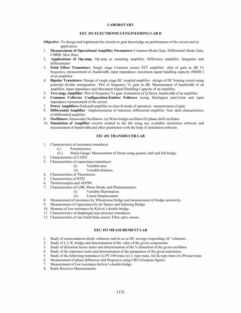
LABOROTARY
EEC 451 ELECTRONICS ENGINEERING LAB II
Objective -To design and implement the circuits to gain knowledge on performance of the circuit and itsapplication.
1. Measurement of Operational Amplifier Parameters-Common Mode Gain, Differential Mode Gain,CMRR, Slew Rate.
2. Applications of Op-amp- Op-amp as summing amplifier, Difference amplifier, Integrator anddifferentiator
3. Field Effect Transistors- Single stage Common source FET amplifier –plot of gain in dB Vsfrequency, measurement of, bandwidth, input impedance, maximum signal handling capacity (MSHC)of an amplifier
4. Bipolar Transistors- Design of single stage RC coupled amplifier –design of DC biasing circuit usingpotential divider arrangement –Plot of frequency Vs gain in dB. Measurement of bandwidth of anamplifier, input impedance and Maximum Signal Handling Capacity of an amplifier.
5. Two stage Amplifier. Plot of frequency Vs gain. Estimation of Q factor, bandwidth of an amplifier6. Common Collector Configuration-Emitter Follower (using Darlington pair)-Gain and input
impedance measurement of the circuit.7. Power Amplifiers-Push pull amplifier in class B mode of operation –measurement of gain.8. Differential Amplifier –Implementation of transistor differential amplifier .Non ideal characteristics
of differential amplifier9. Oscillators -Sinusoidal Oscillators- (a) Wein-bridge oscillator (b) phase shift oscillator10. Simulation of Amplifier circuits studied in the lab using any available simulation software and
measurement of bandwidth and other parameters with the help of simulation software.
EIC 451 TRANSDUCER LAB
1. Characteristics of resistance transducer(i.) Potentiometer(ii.) Strain Gauge/ Measurement of Strain using quarter, half and full bridge.
2. Characteristics of LVDT.3. Characteristics of capacitance transducer:
(i) Variable area(ii) Variable distance.
4. Characteristics of Thermistors5. Characteristics of RTD.6. Thermocouples and AD590.7. Characteristics of LDR, Photo Diode, and Phototransistor:
(i) Variable Illumination.(ii) Linear Displacement.
8. Measurement of resistance by Wheatstone bridge and measurement of bridge sensitivity.9. Measurement of Capacitance by de’Sautys and Schering Bridge.10. Measure of low resistance by Kelvin’s double bridge.11. Characteristics of diaphragm type pressure transducer.12. Characteristics of one Solid State sensor/ Fiber optic sensor,
EEC 453 MEASUREMENT LAB
1. Study of semiconductor diode voltmeter and its us as DC average responding AC voltmeter .2. Study of L.C.R. bridge and determination of the value of the given components.3. Study of distortion factor meter and determination of the % distortion of the given oscillator.4. Study of the transistor tester and determination of the parameters of the given transistors.5. Study of the following transducer (i) PT-100 trans (ii) J- type trans. (iii) K-type trans (iv) Presser trans6. Measurement of phase difference and frequency using CRO (lissajous figure)7. Measurement of low resistance Kelvin’s double bridge.8. Radio Receiver Measurements

(16)
(Revised)ECE 509 Fluid Mechanics
3 1 0
Unit
Topic Chapter/Section
Proposednumber
ofLectures
I Introduction: Fluids and continuum: Physical properties of fluids, ideal and rearfluids, Newtonian and non-Newtonian fluids, measurement of surface tension.Kinematics of Fluid Flow: Steady and unsteady, uniform and non-uniform,laminar and turbulent flows, one, two and three dimensional flows, streamlines,streak lines and path lines, continuity equation, rotation and circulation,elementary explanation of stream function and velocity potential,graphical and experimental methods of drawing flow nets.Fluid statics: Pressure-density-height relationship, manometers, pressure on planeand curved surfaces, centre of pressure, buoyancy, stability of immersed and floatingbodies.
8
II Dynamics of Fluid flow: Euler's equation of motion along a streamline and itsintegration, Bernoulli's equation and its applications-Pitot tube, flow throughorifices, mouthpieces, nozzles, notches, free and forced vortex, momentumequation and its application to stationary and moving vanes, pipe bends, Problemsrelated to combined application of energy and momentum equations, flowmeasurements.
8
III Laminar and Turbulent Flow: Equation of motion for laminar flow throughpipes, Stoke's law, flow between parallel plates, flow through porous media,fluidization, measurement of viscosity, transition from laminar to turbulent flow,turbulent flow, equation for turbulent flow, eddy viscosity, mixing length conceptand velocity distribution in turbulent flow, Hot-wire anemometer and LDA.
8
IV (a) Dimensional Analysis and Hydraulic Similitude: Dimensional analysis,Buckingham's theorem, important dimensionless numbers and theirsignificance, geometric, Kinematic and dynamic similarity, model studies.
(b) Introduction to Boundary Layer.(c) Flow past Submerged Bodies: Drag and lift, drag on a sphere, cylinder and disc, lift
magnus effect and circulation.
8
V (a) Pipe Flow: Nature of turbulent flow in pipes, equation for velocity distributionover smooth and rough surfaces, resistance coefficient and its variation, flow insudden expansion, contraction, diffusers, bends, valves and siphons, concept ofequivalent length, branched pipes, pipes in series and parallel, simple networks.
(b) Compressibility Effects in pipe flow: Transmission of pressure waves inrigid and elastic pipes, water hammer, and analysis of simple surge tankexcluding friction.
8
Text & Reference Book:1. Som and Biswas, “Introduction to fluid mechanics and machines”, TMH2. S. K. Agrawal, “Fluid mechanics and machinery”, TMH3. R. J. Garde, A. G. Mirajgaoker, “Engineering fluid mechanics including hydraulic machines”, Nemchand
& Bros, Roorkee, 2nd Edition, 1983.
Fifth Semester Syllabus: Theory Subjects

(17)
(Revised)EEC 501 INTEGRATED CIRCUITS
3 1 0
Unit Topic Chapter/Section
From Text [1]
Proposednumber ofLectures
I Analog Integrated circuit Design: an overview: Current Mirrors using BJTand MOSFETs, Simple current Mirror, Base current compensated currentMirror, Wilson and Improved Wilson Current Mirrors, Widlar Current sourceand Cascode current Mirror
The 741 IC Op-Amp: Bias circuit, short circuit protection circuitry, the inputstage, the second stage, the output stage, and device parameters; DC Analysis of741: Small Signal Analysis of input stage, the second stage, the output stage;Gain, Frequency Response of 741; a Simplified Model, Slew Rate, RelationshipBetween ft and SR
5.6, 6.4, 6.5
10.1-10.6 8
II Linear Applications of IC op-amps: An Overview of Op-Amp (ideal and nonideal) based Circuits V-I and I-V converters, generalized Impedance converter,simulation of inductors
Filters: First and second order LP, HP, BP BS and All pass active filters, KHN,Tow-Thomas and State Variable Biquad filters; Sinusoidal oscillators
2.2-2.7
11.4, 11.7,12.1, 12.2
8
III Digital Integrated Circuit Design-An Overview: CMOS Logic Gate Circuits:Basic Structure CMOS realization of Inverters, AND, OR, NAND and NORGates
Latches and Flip flops: The Latch, The SR Flip-flop, CMOS Implementation ofSR Flip-flops, A Simpler CMOS Implementation of the Clocked SR Flip-flop,D Flip-flop Circuits.
13.2-13.3
13.7
8
IV Non-Linear applications of IC Op-amps: Log–Anti Log Amplifiers, PrecisionRectifiers, Peak Detectors, Simple and Hold Circuits, Analog Multipliers andtheir applications. Op-amp as a comparator, Zero crossing detector, SchmittTrigger, Astable multivibrator, Monostable multivibrator, Generation ofTriangular Waveforms
12.1, 12.4,12.5 12.9
8
V D/A and A/D converters
Integrated Circuit Timer: The 555 Circuit, Implementing a MonostableMultivibrator Using the 555 IC, Astable Multivibrator Using the 555 IC.
Phase locked loops (PLL): Ex-OR Gates and multipliers as phase detectors,Block Diagram of IC PLL, Working of PLL and Applications of PLL.
10.9-10.11
12.7
6.5 of Ref[2]
8
Text Book:[1] Sedra and Smith, “Microelectronic Circuits”, 4th Edition, Oxford University Press.Reference Books:[2] Michael Jacob, `Applications and Design with Analog Integrated Circuits’, PHI, 2nd Edn, 2006[3] Jacob Milliman and Arvin Grabel, “Microelectronics”, 2nd Edition, TMH, 2008.

(18)
Unit EIC 501 CONTROL SYSTEM - I Text Book/Chapter
Lectures
I Introduction: Basic Components of a control system, Feedback and its effect, types of feed back control systems. Blockdiagrams and signal flow graphs, Modeling of Physicalsystems
1.1 to 1.33.1 to 3.24.1 to 4.3, 4.5to 4.6
8
II State-Variable Analysis: Introduction, Vector matrixrepresentation of State equation, State Transition Matrix,State-Transition Equation, Relationship between StateEquations and High-order Differential Equations,Relationship between State Equations and Transfer Functions.
5.1 to 5.6 8
III Time domain Analysis of Control Systems: Time response ofcontinuous data systems, typical test signals for the timeresponse of control systems, the unit step response and time-domain specifications, Steady-State error, Time response of aFirst order system, Transient response of a Prototype secondorder system
7.1 to 7.6 8
IV Stability of Linear Control Systems: Introduction, Bounded-Input Bounded-output Stability Continuous Data Systems,Zero-input and asymptotic stability of continuous datasystems, Methods of determining stability, RH criterion.
6.1 to 6.5 8
V Frequency Domain Analysis: Introduction: Mr ωr andBandwidth of the Prototype Second Order System ,Effects ofAdding a zero to the Forward path, Effects of Adding a poleto the Forward Path, Nyquist Stability criterion, RelativeStability: Gain Margin and Phase Margin, Stability Analysiswith the Bode Plot
9.1to 9.11 10
Text Book: B.C. Kuo, “Automatic Control Systems” ,8th Edition, John WileyReference Books:
1. I. J Nagrath & M Gopal, Control System Engineering; New Age International publishers2. ,Joseph J Distefano III, Allen R Stubberud, Ivan J Williams, Control Systems Shaums out lines Series , 3rd
Edition, Mc Graw Hill.
(19)
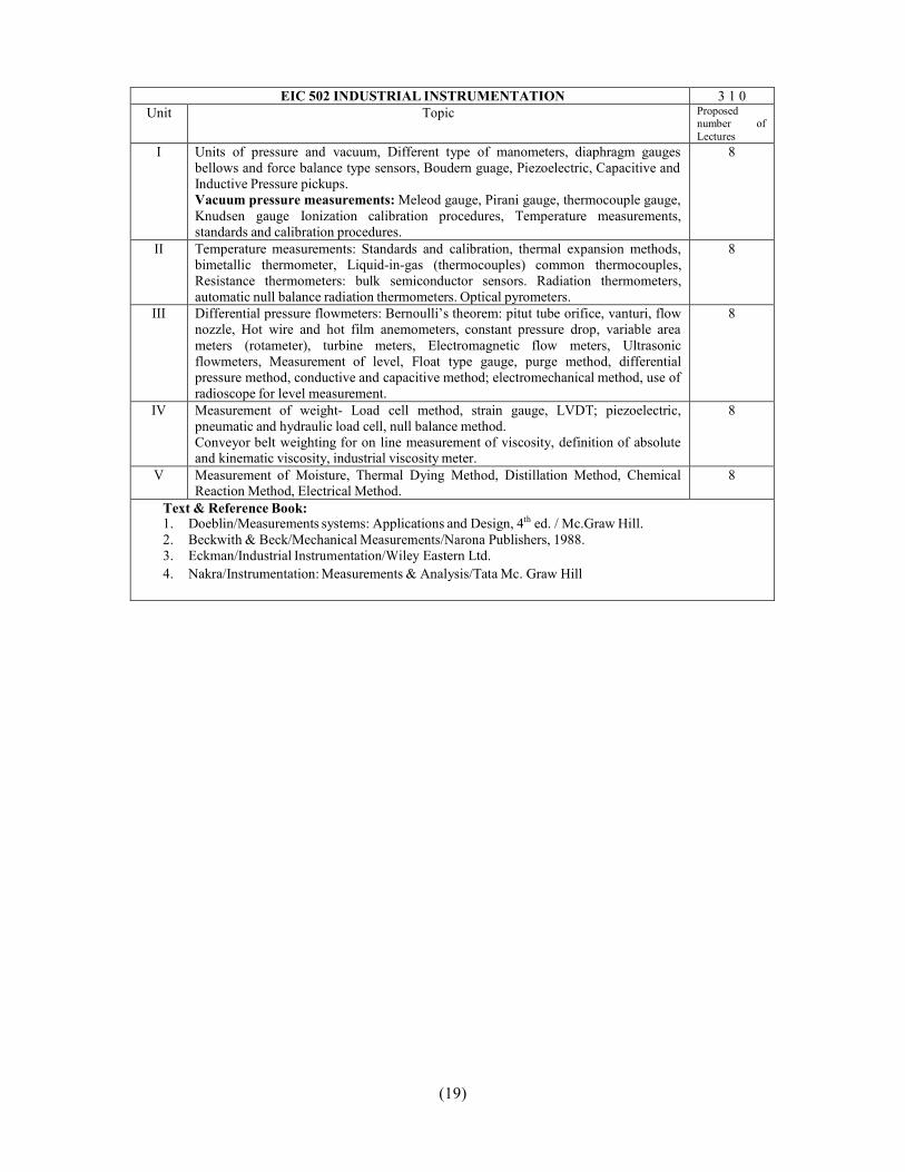
EIC 502 INDUSTRIAL INSTRUMENTATION 3 1 0Unit Topic Proposed
number ofLectures
I Units of pressure and vacuum, Different type of manometers, diaphragm gaugesbellows and force balance type sensors, Boudern guage, Piezoelectric, Capacitive andInductive Pressure pickups.Vacuum pressure measurements: Meleod gauge, Pirani gauge, thermocouple gauge,Knudsen gauge Ionization calibration procedures, Temperature measurements,standards and calibration procedures.
8
II Temperature measurements: Standards and calibration, thermal expansion methods,bimetallic thermometer, Liquid-in-gas (thermocouples) common thermocouples,Resistance thermometers: bulk semiconductor sensors. Radiation thermometers,automatic null balance radiation thermometers. Optical pyrometers.
8
III Differential pressure flowmeters: Bernoulli’s theorem: pitut tube orifice, vanturi, flownozzle, Hot wire and hot film anemometers, constant pressure drop, variable areameters (rotameter), turbine meters, Electromagnetic flow meters, Ultrasonicflowmeters, Measurement of level, Float type gauge, purge method, differentialpressure method, conductive and capacitive method; electromechanical method, use ofradioscope for level measurement.
8
IV Measurement of weight- Load cell method, strain gauge, LVDT; piezoelectric,pneumatic and hydraulic load cell, null balance method.Conveyor belt weighting for on line measurement of viscosity, definition of absoluteand kinematic viscosity, industrial viscosity meter.
8
V Measurement of Moisture, Thermal Dying Method, Distillation Method, ChemicalReaction Method, Electrical Method.
8
Text & Reference Book:1. Doeblin/Measurements systems: Applications and Design, 4th ed. / Mc.Graw Hill.2. Beckwith & Beck/Mechanical Measurements/Narona Publishers, 1988.3. Eckman/Industrial Instrumentation/Wiley Eastern Ltd.4. Nakra/Instrumentation: Measurements & Analysis/Tata Mc. Graw Hill
(20)
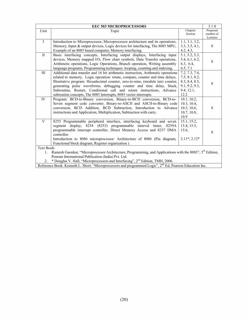
EEC 503 MICROPROCESSORS 3 1 0Unit Topic Chapter/
SectionProposednumber ofLectures
I Introduction to Microprocessor, Microprocessor architecture and its operations,Memory, Input & output devices, Logic devices for interfacing, The 8085 MPU,Example of an 8085 based computer, Memory interfacing.
1.1, 3.1, 3.2,3.3, 3.5, 4.1,4.2, 4.3,
8
II Basic interfacing concepts, Interfacing output displays, Interfacing inputdevices, Memory mapped I/O, Flow chart symbols, Data Transfer operations,Arithmetic operations, Logic Operations, Branch operation, Writing assemblylanguage programs, Programming techniques: looping, counting and indexing.
5.1, 5.2, 5.3,5.4, 6.1, 6.2,6.3, 6.4,6.5, 7.1
8
III Additional data transfer and 16 bit arithmetic instruction, Arithmetic operationsrelated to memory, Logic operation: rotate, compare, counter and time delays,Illustrative program: Hexadecimal counter, zero-to-nine, (module ten) counter,generating pulse waveforms, debugging counter and time delay, Stack,Subroutine, Restart, Conditional call and return instructions, Advancesubroutine concepts, The 8085 Interrupts, 8085 vector interrupts.
7.2, 7.3, 7.4,7.5, 8.1, 8.2,8.3, 8.4, 8.5,9.1, 9.2, 9.3,9.4, 12.1,12.2
8
IV Program: BCD-to-Binary conversion, Binary-to-BCD conversion, BCD-to-Seven segment code converter, Binary-to-ASCII and ASCII-to-Binary codeconversion, BCD Addition, BCD Subtraction, Introduction to Advanceinstructions and Application, Multiplication, Subtraction with carry.
10.1, 10.2,10.3, 10.4,10.5, 10.6,10.7, 10.8,10.9
8
V 8255 Programmable peripheral interface, interfacing keyboard and sevensegment display, 8254 (8253) programmable interval timer, 8259Aprogrammable interrupt controller, Direct Memory Access and 8237 DMAcontroller.Introduction to 8086 microprocessor: Architecture of 8086 (Pin diagram,Functional block diagram, Register organization ).
15.1, 15.2,15.4, 15.5,15.6,
2.11*, 2.12*
8
Text Book:1. Ramesh Gaonkar, “Microprocessor Architecture, Programming, and Applications with the 8085”, 5th Edition,
Penram International Publication (India) Pvt. Ltd.2. * Douglas V. Hall, “Microprocessors and Interfacing”, 2nd Edition, TMH, 2006.
Reference Book: Kenneth L. Short, “Microprocessors and programmed Logic”, 2nd Ed, Pearson Education Inc.

(21)
LABOROTARY
EEC 551 INTEGRATED CIRCUITS LABObjective: - To design and implement the circuits to gain knowledge on performance of the circuit and its
application. These circuits should also be simulated on Pspice.1. Log and antilog amplifiers.2. Voltage comparator and zero crossing detectors.3. Second order filters using operational amplifier for–
a. Low pass filter of cutoff frequency 1 KHz.b. High pass filter of frequency 12 KHz.c. Band pass filter with unit gain of pass band from 1 KHz to 12 KHz.
4. Wien bridge oscillator using operational amplifier.5. Determine capture range; lock in range and free running frequency of PLL.6. Voltage regulator using operational amplifier to produce output of 12V with maximum load current of
50 mA.7. A/D and D/A convertor.8. Voltage to current and current to voltage convertors.9. Function generator using operational amplifier (sine, triangular & square wave)10. Astable and monostable multivibrator using IC 555.
EIC 551 CONTROL SYSTEM LAB I1. DC SPEED CONTROL SYSTEM
(a) To study D.C. speed control system on open loop and close loop.(b) To study of Transient performance, another time signal is added at the input of control Circuit.(c) To study how eddy current breaking is being disturbance rejected by close and open loop.
2. DC MOTOR POSITION CONTROL(a) To study of potentiometer displacement constant on D.C. motor position control.(b) To study of D. C. position control through continuous command.(c) To study of D.C. position control through step command.(d) To study of D.C. position control through Dynamic response.
3. AC MOTOR POSITION CONTROL(a) To study of A.C. motor position control through continuous command.(b) To study of error detector on A.C. motor position control through step command.(c) To study of A.C. position control through dynamic response.
4. MAGNETIC AMPLIFIER(a) To study Input / Output characteristic of a magnetic amplifier in mode (i) Saturable Reactor, (ii) Self
Saturable Reactor.5. SYNCHRO TRANSMITTER / RECEIVER
(a) To study of Synchro Transmitter in term of Position v/s Phase and voltage magnitude with respect toRotor Voltage Magnitude/Phase.
(b) To study of remote position indication system using Synchro-transmitter/receiver.6. PID CONTROLLER
(a) To observe open loop performance of building block and calibration of PID Controls.(b) To study P, PI and PID controller with type 0 system with delay.(c) To study P, PI and PID controller with type 1 system.
7. LEAD LAG COMPENSATOR(a) To study the open loop response on compensator.
(b) Close loop transient response.8. LINEAR SYSTEM SIMULATOR
(a) Open loop response(i) Error detector with gain, (ii) Time constant, (iii) Integrator(b) Close loop system
(I) First order system (II) Second order system (III) Third order system9. Introduction to MATLAB (Control System Toolbox), Implement at least any two experiment in
MATLAB.a. Different Toolboxes in MATLAB, Introduction to Control Systems Toolbox.b. Determine transpose, inverse values of given matrix.c. Plot the pole-zero configuration in s-plane for the given transfer function.d. Determine the transfer function for given closed loop system in block diagram representation.e. Plot unit step response of given transfer function and find peak overshoot, peak time.
(22)
f. Plot unit step response and to find rise time and delay time.g. Plot locus of given transfer function, locate closed loop poles for different values of k.h. Plot root locus of given transfer function and to find out S, Wd, Wn at given root & to discuss
stability.i. Plot bode plot of given transfer function.j. Plot bode plot of given transfer function and find gain and phase marginsk. Plot Nyquist plot for given transfer function and to compare their relative stabilityl. Plot the Nyquist plot for given transfer function and to discuss closed loop stability, gain and
phase margin.
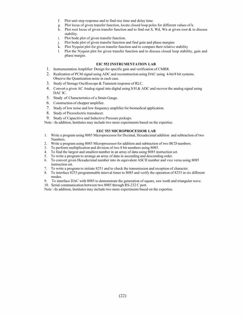
EIC 552 INSTRUMENTATION LAB1. Instrumentation Amplifier: Design for specific gain and verification of CMRR.2. Realization of PCM signal using ADC and reconstruction using DAC using 4-bit/8 bit systems.
Observe the Quantization noise in each case.3. Study of Storage Oscilloscope & Transient response of RLC.4. Convert a given AC Analog signal into digital using S/H & ADC and recover the analog signal using
DAC IC.5. Study of Characteristics of a Strain Gauge.6. Construction of chopper amplifier.7. Study of low noise and low frequency amplifier for biomedical application.8. Study of Piezoelectric transducer.9. Study of Capacitive and Inductive Pressure pickups.
Note :-In addition, Institutes may include two more experiments based on the expertise.
EEC 553 MICROPROCESSOR LAB1. Write a program using 8085 Microprocessor for Decimal, Hexadecimal addition and subtraction of two
Numbers.2. Write a program using 8085 Microprocessor for addition and subtraction of two BCD numbers.3. To perform multiplication and division of two 8 bit numbers using 8085.4. To find the largest and smallest number in an array of data using 8085 instruction set.5. To write a program to arrange an array of data in ascending and descending order.6. To convert given Hexadecimal number into its equivalent ASCII number and vice versa using 8085
instruction set.7. To write a program to initiate 8251 and to check the transmission and reception of character.8. To interface 8253 programmable interval timer to 8085 and verify the operation of 8253 in six different
modes.9. To interface DAC with 8085 to demonstrate the generation of square, saw tooth and triangular wave.10. Serial communication between two 8085 through RS-232 C port.Note :-In addition, Institutes may include two more experiments based on the expertise.
(23)
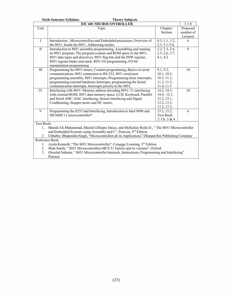
EIC 601 MICROCONTROLLER 3 1 0Unit Topic Chapter/
SectionProposednumber ofLectures
I Introduction , Microcontrollers and Embedded processors, Overview ofthe 8051, Inside the 8051, Addressing modes,
0.3, 1.1, 1.2,2.1, 5.1-5.4,
6
II Introduction to 8051 assembly programming, Assembling and runningan 8051 program, The program counter and ROM space in the 8051,8051 data types and directives, 8051 flag bits and the PSW register,8051 register banks and stack, 8051 I/O programming, I/O bitmanipulation programming.
2.2, 2.3, 2.4,2.5, 2.6, 2.7,4.1, 4.2
8
III Programming the 8051 timers, Counter programming, Basics of serialcommunications, 8051 connection to RS-232, 8051 serial portprogramming assembly, 8051 interrupts, Programming timer interrupts,programming external hardware interrupts, programming the Serialcommunication interrupts, Interrupts priority in the 8051,
9.1, 9.2,10.1, 10.2,10.3, 11.1,11.2, 11.3,11.4, 11.5
10
IV Interfacing with 8051: Memory address decoding 8031/ 51 interfacingwith external ROM, 8051 data memory space, LCD, Keyboard, Paralleland Serial ADC, DAC interfacing, Sensor interfacing and SignalConditioning, Stepper motor and DC motor,
14.2, 14.3,14.4, 12.1,12.2, 13.1,13.2, 13.3,17.2, 17.3,
10
V Programming the 8255 and Interfacing, Introduction to Intel 8096 andMC68HC11 microcontroller*.
15.1, 15.2,Text Book2: Ch. 3 & 4
6
Text Book:1. Mazidi Ali Muhammad, Mazidi Gillispie Janice, and McKinlay Rolin D., “ The 8051 Microcontroller
and Embedded Systems using Assembly and C”, Pearson, 2nd Edition.2. Chhabra Bhupendra Singh, “Microcontrollers & its Applications” Dhanpat Rai Publishing Company
Reference Book:1. Ayala Kenneth, “The 8051 Microcontroller”, Cengage Learning, 3rd Edition2. Shah Satish, “ 8051 Microcontrollers MCS 51 Family and its variants”, Oxford3. Ghoshal Subrata, “ 8051 Microcontroller Internals, Instructions, Programming and Interfacing”
Pearson
Sixth Semester Syllabus: Theory Subjects

(24)
EIC 602 ELECTRICAL MACHINES 3 1 0Unit Topic Chapter/
SectionProposednumber ofLectures
I Basic concept of rotating machines: Elementary machines –synchronous machines, dc machine, generated emf, rotating magneticfield, torque in round rotor machines. Operations of Basic Machinetypes – synchronous, asynchronous, ac machines, dc machines,matching characteristics of electric machines and load.
5.1-5.3, 5.5 –5.7, 5.11
8
II DC Machine: Introduction, emf equation, torque equation, powerbalance, linear magnetization, circuit model, generating mode,motoring mode, armature reaction, compensating winding,commutation, method of excitation, characteristics of dc shunt, seriesand compound motors and generators. Starting of dc motor, speedcontrol of dc motor, breaking of dc motor.
7.1-7.8, 7.11-7.15
8
III Synchronous machines: Introduction of basic synchronous machinemodel, circuit model of synchronous machine, determination ofarmature reaction ampere turn and leakage reactance of synchronousmachine, synchronizing to infinite bus bar, operating characteristics,power flow equations, parallel operation of synchronous generators,hunting in synchronous machines.
8.2 – 8.5, 8.7– 8.9, 8.12,8.13 8
IV Induction Motor: Introduction, construction, flux and mmf phasor ininduction motors, slip and frequency of rotor currents, rotor emf,power, induction motor phasor diagram, torque slip characteristics,determination of equivalent circuit parameters, circle diagram, startingof induction motor, speed control.
9.1 – 9.10
8
V Single Phase Motors: Introduction, types of single phase motor, singlephase induction motor, split phase motors, single phase commutatormotor, single phase synchronous motor, stepper motor.
10.1 – 10.68
Text Book: D P Kothari & I J Nagrath, “Electric Machines”, Tata McGraw Hill Education Pvt Ltd, 3rd Edition,2004.Reference Books: A. Fitzgerald, C. Kingsley and S Umans , “Electric Machinery”, Tata McGraw HillEducation Pvt Ltd, 6th Edition, 2002.

(25)
EEC 609 COMMUNICATION ENGINEERING 3 1 0Unit Topic Chapter/ Section Proposed
number ofLectures
I 1. Introduction:The Communication Process, The Layered Approach, Example ofcommunication2. Amplitude Modulation:Introduction, Amplitude modulation, Double Sideband-SuppressedCarrier modulation, Quadrature-Carrier Multiplexing, Single-Sidebandand Vestigial-Sideband Methods of modulation, VSB Transmission ofAnalog and Digital Television, Frequency Translation, Frequency-Division Multiplexing
1.1 to 1.3
3.1 to 3.8 8
II 3. Phase and Frequency Modulation:Introduction, Basic Definitions, Frequency Modulation, Phase-LockedLoop, Nonlinear Effects in FM Systems, The Super-heterodyne Receiver,Analog and Digital FM Cellular Telephones
4.1 to 4.7
8
III 4. Noise in Analog Modulation:Introduction, Receiver Model, Noise in DSB-SC Receivers, Noise in AMreceivers, Noise in FM Receivers, Pre-emphasis and De-emphasis in FM5. Digital Representation of Analog Signals:Introduction, Digitization of Analog Sources, The Sampling Process,Pulse-Amplitude Modulation, Time-Division Multiplexing, Pulse-Position Modulation, PPM in Impulse Radio, The Quantization Process,Pulse-Code Modulation, Delta Modulation, Digitization of Video andMPEG,
6.1 to 6.6
7.1 to 7.108
IV 6. Base band Transmission of digital Signals:Introduction, Baseband Pulses and matched Filter Detection, Probabilityof Error Due to Noise, Inter symbol Interference, Eye Pattern, NyquistCriterion for Distortion less Transmission, Baseband M-ary PAMTransmission, Tapped Delay Line Equalization, Transmission of 100Mbps Over Twisted Pair
8.1 to 8.9
8
V 7. Band-Pass Transmission of Digital Signals:Introduction, band-Pass Transmission Model, Transmission Binary PSKand FSK, M-ary Data Transmission Systems, Comparison of NoisePerformances of various PSK and FSK ?Systems, Orthogonal FrequencyDivision Multiplexing (OFDM),8. Information and Forward Error Correction:Introduction, uncertainty, Information and Entropy, Source-CodingTheorem, Lossless Data Compression
9.1 to 9.6
10.1 to 10.48
Text Book:1. Simon Haykin & Michael Moher “Communication Systems”, 5th Edition, Wiley India Publication.
Reference Books:1. B.P. Lathi & Zhi Ding , “ Modern Digital and Analog Communication Systems” International 4th Ed.
Oxford University Press
(26)
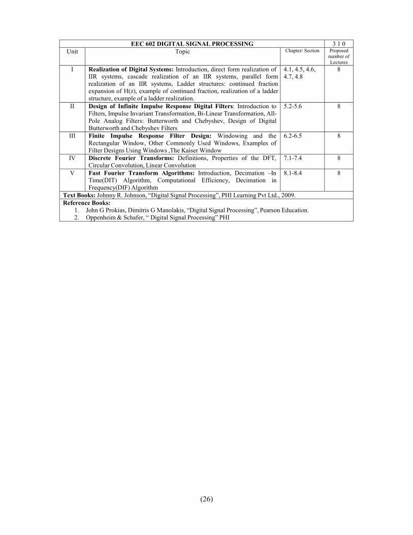
EEC 602 DIGITAL SIGNAL PROCESSING 3 1 0Unit Topic Chapter/ Section Proposed
number ofLectures
I Realization of Digital Systems: Introduction, direct form realization ofIIR systems, cascade realization of an IIR systems, parallel formrealization of an IIR systems, Ladder structures: continued fractionexpansion of H(z), example of continued fraction, realization of a ladderstructure, example of a ladder realization.
4.1, 4.5, 4.6,4.7, 4.8
8
II Design of Infinite Impulse Response Digital Filters: Introduction toFilters, Impulse Invariant Transformation, Bi-Linear Transformation, All-Pole Analog Filters: Butterworth and Chebyshev, Design of DigitalButterworth and Chebyshev Filters
5.2-5.6 8
III Finite Impulse Response Filter Design: Windowing and theRectangular Window, Other Commonly Used Windows, Examples ofFilter Designs Using Windows ,The Kaiser Window
6.2-6.5 8
IV Discrete Fourier Transforms: Definitions, Properties of the DFT,Circular Convolution, Linear Convolution
7.1-7.4 8
V Fast Fourier Transform Algorithms: Introduction, Decimation –InTime(DIT) Algorithm, Computational Efficiency, Decimation inFrequency(DIF) Algorithm
8.1-8.4 8
Text Books: Johnny R. Johnson, “Digital Signal Processing”, PHI Learning Pvt Ltd., 2009.Reference Books:
1. John G Prokias, Dimitris G Manolakis, “Digital Signal Processing”, Pearson Education.2. Oppenheim & Schafer, “ Digital Signal Processing” PHI
(27)
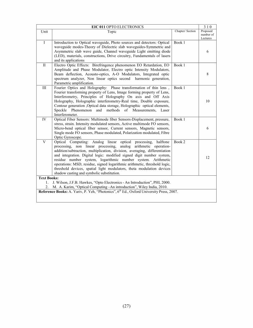
EIC 011 OPTO ELECTRONICS 3 1 0Unit Topic Chapter/ Section Proposed
number ofLectures
I Introduction to Optical waveguide, Photo sources and detectors: Opticalwaveguide modes-Theory of Dielectric slab waveguides-Symmetric andAsymmetric slab wave guide, Channel waveguide Light emitting diode(LED), materials, constructions, Drive circuitry, Fundamentals of lasersand its applications
Book 1
6
II Electro Optic Effects: Birefringence phenomenon EO Retardation, EOAmplitude and Phase Modulator, Electro optic Intensity Modulators,Beam deflection, Acousto-optics, A-O Modulators, Integrated opticspectrum analyzer, Non linear optics second harmonic generation,Parametric amplification.
Book 1
8
III Fourier Optics and Holography: Phase transformation of thin lens ,Fourier transforming property of Lens, Image forming property of Lens,Interferometry, Principles of Holography On axis and Off AxisHolography, Holographic interferometry-Real time, Double exposure,Contour generation ,Optical data storage, Holographic optical elements,Speckle Phenomenon and methods of Measurements, LaserInterferometer.
Book 1
10
IV Optical Fiber Sensors: Multimode fiber Sensors-Displacement, pressure,stress, strain. Intensity modulated sensors, Active multimode FO sensors,Micro-bend optical fiber sensor, Current sensors, Magnetic sensors,Single mode FO sensors, Phase modulated, Polarization modulated, FibreOptic Gyroscope.
Book 1
6
V Optical Computing: Analog linear optical processing, halftoneprocessing, non linear processing, analog arithmetic operation-addition/subtraction, multiplication, division, averaging, differentiationand integration. Digital logic: modified signed digit number system,residue number system, logarithmic number system. Arithmeticoperations: MSD, residue, signed logarithmic arithmetic, threshold logic,threshold devices, spatial light modulators, theta modulation devicesshadow casting and symbolic substitution.
Book 2
12
Text Books:1. J. Wilson, J.F.B. Hawkes, “Opto Electronics - An Introduction”, PHI, 2000.2. M. A. Karim, “Optical Computing –An introduction”, Wiley India, 2010.
Reference Books: A. Yariv, P. Yeh, “Photonics”, 6th Ed., Oxford University Press, 2007.
(28)
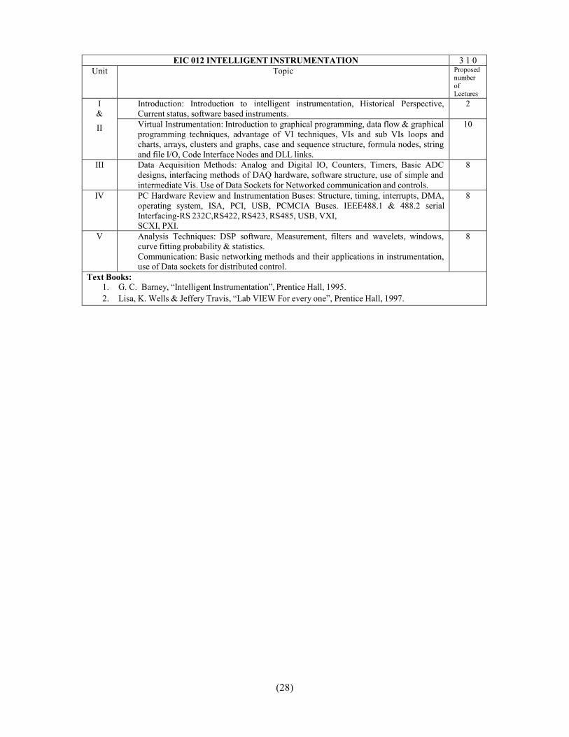
EIC 012 INTELLIGENT INSTRUMENTATION 3 1 0Unit Topic Proposed
numberofLectures
I&II
Introduction: Introduction to intelligent instrumentation, Historical Perspective,Current status, software based instruments.
2
Virtual Instrumentation: Introduction to graphical programming, data flow & graphicalprogramming techniques, advantage of VI techniques, VIs and sub VIs loops andcharts, arrays, clusters and graphs, case and sequence structure, formula nodes, stringand file I/O, Code Interface Nodes and DLL links.
10
III Data Acquisition Methods: Analog and Digital IO, Counters, Timers, Basic ADCdesigns, interfacing methods of DAQ hardware, software structure, use of simple andintermediate Vis. Use of Data Sockets for Networked communication and controls.
8
IV PC Hardware Review and Instrumentation Buses: Structure, timing, interrupts, DMA,operating system, ISA, PCI, USB, PCMCIA Buses. IEEE488.1 & 488.2 serialInterfacing-RS 232C,RS422, RS423, RS485, USB, VXI,SCXI, PXI.
8
V Analysis Techniques: DSP software, Measurement, filters and wavelets, windows,curve fitting probability & statistics.Communication: Basic networking methods and their applications in instrumentation,use of Data sockets for distributed control.
8
Text Books:1. G. C. Barney, “Intelligent Instrumentation”, Prentice Hall, 1995.2. Lisa, K. Wells & Jeffery Travis, “Lab VIEW For every one”, Prentice Hall, 1997.

(29)
EEC 012 DATA STRUCTURE 3 1 0Unit Topic Chapter/
SectionProposednumber
ofLectures
I Introduction: Basic Terminology, Elementary Data Organization,Algorithm, Efficiency of an Algorithm, Time and Space Complexity,Asymptotic notations: Big-Oh, time-Space trade-off, Abstract Data Types(ADT)Arrays: Definition, Single and Multidimensional Arrays, Representation ofArrays: Row major Order, and Column Major Order, Application of arrays,Sparse Matrices and their representations.Linked lists: Array Implementation and Dynamic Implementation of SinglyLinked Lists, Doubly Linked List, Circularly Linked List, Operations on aLinked List, Insertion, Deletion, Traversal, Polynomial Representation andAddition, Generalized Linked List.
8
II Stacks: Abstract Data Type, Primitive Stack operations: Push & Pop, Arrayand Linked Implementation of Stack in C, Application of stack: Prefix andPostfix Expressions, Evaluation of Postfix expression, Recursion, Tower ofHanoi Problem, Simulating Recursion, Principles of recursion, Tail recursion,Removal of recursion.Queues: Operations of Queue: Create, Add, Delete, Full and Empty, Circularqueues, Array and linked implementation of queues in C, Dequeue andPriority Queue
8
III Trees: Basic terminology, Binary Trees, Binary Tree Representation: ArrayRepresentation and Dynamic Representation, Complete Binary Tree,Algebraic Expressions, Extended Binary Trees, Array and LinkedRepresentation of Binary trees, Tree Traversal algorithms: In-order, Pre-orderand Post-order, Threaded Binary trees, Traversing Threaded Binary trees,Huffman algorithm.
8
IV Graphs: Terminology, Sequential and linked Representations, of Graphs:Adjacency Matrices, Adjacency List, Adjacency Multi list, Graph Traversal:Depth First Search and Breadth first Search, Connected Component,Spanning Trees, Minimum Cost Spanning Trees: Prims and Kurskalalgorithm, Transitive Closure and Shortest Path algorithm: WarshalAlgorithm and Dijikstra Algorithm, Introduction to Activity Networks.
8
V Searching: Sequential search, Binary search, Comparison and Analysis,Internal Sorting: Insertion Sort, selection, Bubble Sort, Quick Sort, TwoWay Merge Sort, Heap Sort, Radix Sort, Practical consideration for InternalSorting.Search Trees: Binary Search Trees (BST), Insertion and Deletion in BST,Complexity of search Algorithm, AVL trees, Introduction to m-way SearchTrees, B Trees & B+ Trees Storage Management: Garbage Collection andCompaction.
8
Text Book:1. Aaron M. Tenenbaum, Yedidyah Langsam and Moshe J. Augenstein “Data structures Using C and
C++”, PHI2. Lipschutz, “Data Structures” Schaum’s Outline Series, TMH
Reference Books:1. Horowitz and Sahani, “Fundamentals of Data Structures”, Galgotia Publication

(30)
EEC 603 MICROWAVE ENGINEERING 3 1 0Unit Topic Chapter/ Section Proposed
number ofLectures
I Rectangular Wave Guide: Field Components, TE, TM Modes, DominantTE10 mode, Field Distribution, Power, Attenuation. Circular Waveguides:TE, TM modes. Wave Velocities, Micro strip Transmission line (TL),Coupled TL, Strip TL, Coupled Strip Line, Coplanar TL, MicrowaveCavities,
4.1-4-3,11.0-11.3
8
II Scattering Matrix , Passive microwave devices: Microwave HybridCircuits. , Terminations, Attenuators, Phase Shifters, DirectionalCouplers: Two Hole directional couplers, S Matrix of a Directionalcoupler, Hybrid Couplers, Microwave Propagation in ferrites, FaradayRotation, Isolators, Circulators. S parameter analysis of all components.
4.4-4.6
8
III Microwave Tubes: Limitation of Conventional Active Devices atMicrowave frequency, Two Cavity Klystron, Reflex Klystron,Magnetron, Traveling Wave Tube, Backward Wave Oscillators: TheirSchematic, Principle of Operation, Performance Characteristic and theirapplications.
9.0-9.5, 10.0-10.2
8
IV Solid state amplifiers and oscillators: Microwave Bipolar Transistor,Microwave tunnel diode, Microwave Field-effect Transistor, Transferredelectron devices, Avalanche Transit –time devices: IMPATT Diode,TRAPPAT Diode,
5.0-5.1,5.3,6.0-6.1,7.0-7.3 10
V Microwave Measurements: General set up of a microwave test bench,Slotted line carriage, VSWR Meter, microwave power measurementstechniques, Crystal Detector, frequency measurement, wavelengthmeasurements, Impedance and Refection coefficient, VSWR, Insertionand attenuation loss measurements, measurement of antennacharacteristics, microwave link design.
14.1-14.4(Book 2)
8
Text Books:3. Samuel Y. Liao, “Microwave Devices and Circuits”, 3rd Ed, Pearson Education.4. A. Das and S. K. Das, “Microwave Engineering”, TMH.
Reference Books:1. R.E Collin, “Foundation for Microwave Engineering “, 2nd Ed., John Wiley India.

(31)
LABORATORY
EIC 651 MICRO CONTROLLER LAB1. Write a program of Flashing LED connected to port 1 of the Micro Controller2. Write a program to show the use of INT0 and INT1.3. Write a program to generate 10 kHz square wave.4. Write a program to generate 10 kHz frequency using interrupts.5. Write a program for temperature & to display on intelligent LCD display6. Write a program to demonstrate the polling of Interrupt of 8051/8031 micro controllers.7. Write a program to generate a Ramp waveform using DAC with micro controller.8. Write a program to control a stepper motor in direction, speed and number of steps.9. Write a program to control the speed of DC motor.10.Write a program to interface Microcontroller with 8255.11.Write a program to set the Baud rate at 9600 , 8 Bit data and 1 Stop bit, to send the text string
“Microcontroller” to serial port 1.
EEC-652 DIGITAL SIGNAL PROCESSING LAB1. With the help of Fourier series, make a square wave from sine wave and cosine waves. Find out coefficient
values.2. Evaluate 4 point DFT of and IDFT of x(n) = 1, 0 ≤ n ≤ 3; 0 elsewhere.3. Implement the FIR Filters for 2 KHz cutoff frequency and 2 KHz bandwidth for band pass filter.4. Design FIR filter using Fourier series expansion method.5. Implement IIR low pass filter for a 4 KHz cutoff frequency and compare it the FIR filter with the same type
use chirp as input signal.6. Verify Blackman and Hamming windowing techniques for square wave as an input which window will give
good results.7. Implement the filter functions.8. Generate DTMF sequence 1234567890*# and observe its spectrogram.9. Generate an Amplitude Modulation having side low frequencies 1200 Hz and 800 Hz. Observe and verify the
theoretical FFT characteristics with the observed ones.10. Generate Frequency Modulation having carrier frequencies 1 KHz and modulating frequency 200 Hz with the
modulation index of 0.7. Observe and verify the theoretical FFT characteristics with the observed ones.11. Generate an FSK wave form for transmitting the digital data of the given bit sequence. Predict and verify the
FFT for the same one.12. To study the circular convolution.
EEC 659 COMMUNICATION LAB1. To study DSB/ SSB amplitude modulation & determine its modulation factor & power in side bands.2. To study amplitude demodulation by linear diode detector3. To study frequency modulation and determine its modulation factor4. To study sampling and reconstruction of Pulse Amplitude modulation system.5. To study Pulse Width Modulation and Pulse Position Modulation.6. To construct a triangular wave with the help of Fundamental Frequency and its Harmonic component.7. To construct a Square wave with the help of Fundamental Frequency and its Harmonic component.8. Study of Pulse code modulation (PCM) and its demodulation using Bread Board.9. Study of Amplitude shift keying modulator and demodulator.10. Study of Frequency shift keying modulator and demodulator.11. Study of Phase shift keying modulator and demodulator.


