111 0757670 0637653 bL7 IBI ASME B31.3 INTERPRETATIONS NO. 17 Replies to Technical Inquiries April 1,198 Through November 31, 1W General Information It has been agreed to publish interpretations issued by the B31 Committee concerning B31.3 as part of the update service to the Code. The interpretations have been assigned numbers in chronological order. Each interpretationappliestotheEditionorAddendastated in theinterpretation,or if none is stated,totheEditionorAddenda in effect on thedate of issuance of theinterpretation.Subsequent revisionstotheCode may have superseded the reply. These replies are taken verbatim from the original letters, except for a few typographical and editorial corrections made for the purpose of improved clarity. In some instances, a review of the interpretation revealed a need for corrections of a technical nature. In these cases, a revised reply bearing the original interpretation number with the suffix R is presented. ASME procedures provide for reconsideration of these interpretations when or if additional information is available which the inquirer believes might ‘affect the interpretation. Further, persons aggrieved by an interpretation may appeal to the cognizant ASME committee or subcommittee. As stated in the Statement of Policy in the Code documents, ASME does not “approve,” “certify.” “rate,’. or “endorse” any item,construction,proprietarydevice, or activity. For detailed instructions on preparation of technical inquiries to the B3 1 Committee, refer to Appendix Z. Code Reference and Subject Indexes L Code Reference and Subject Indexes have been prepared to assist the user in locating interpretations by location or by subjectmatter in theCode.TheycoverinterpretationsissuedfromVolume 1 up to and including the present volume, and will be updated with each volume. 197 COPYRIGHT American Society of Mechanical Engineers Licensed by Information Handling Services COPYRIGHT American Society of Mechanical Engineers Licensed by Information Handling Services
Transcript
111 0757670 0637653 bL7 IBI
ASME B31.3
INTERPRETATIONS NO. 17
Replies to Technical Inquiries April 1,198 Through November 31, 1W
General Information
It has been agreed to publish interpretations issued by the B31 Committee concerning B31.3 as part of the update service to the Code. The interpretations have been assigned numbers in chronological order. Each interpretation applies to the Edition or Addenda stated in the interpretation, or if none is stated, to the Edition or Addenda in effect on the date of issuance of the interpretation. Subsequent revisions to the Code may have superseded the reply.
These replies are taken verbatim from the original letters, except for a few typographical and editorial corrections made for the purpose of improved clarity. In some instances, a review of the interpretation revealed a need for corrections of a technical nature. In these cases, a revised reply bearing the original interpretation number with the suffix R is presented.
ASME procedures provide for reconsideration of these interpretations when or if additional information is available which the inquirer believes might ‘affect the interpretation. Further, persons aggrieved by an interpretation may appeal to the cognizant ASME committee or subcommittee. As stated in the Statement of Policy in the Code documents, ASME does not “approve,” “certify.” “rate,’. or “endorse” any item, construction, proprietary device, or activity.
For detailed instructions on preparation of technical inquiries to the B3 1 Committee, refer to Appendix Z.
Code Reference and Subject Indexes L
Code Reference and Subject Indexes have been prepared to assist the user in locating interpretations by location or by subject matter in the Code. They cover interpretations issued from Volume 1 up to and including the present volume, and will be updated with each volume.
197
COPYRIGHT American Society of Mechanical EngineersLicensed by Information Handling ServicesCOPYRIGHT American Society of Mechanical EngineersLicensed by Information Handling Services
B31.3 Suhject Interpretation . Appendix V . Allowable Variation in Elevated Temperature Service ................. 17-17 Para . 300.2. Delining Piping Components ...................................... Para . 301.3, Design Temperatures ............................................
17-23 17-07
Para . 302.2.2, Listcd Components Not Having Specitic Ratings .................... 17-1 I Para . 302.2.4. Allowances for Pressure and Temperature Variation .................. 17-12
Para . 302.3.5(d). Limits of Calculation Stresses Due to Susttained Loads 17-04
Pira. 304.3.3. Reinforcement of Welded Branch Connections ...................... 17-26
Para . 302.3.5(c). Longitudinal stress .......................................... 17-18
and Displacement Strains ..................................................
Para . 322.3. Instrument Piping ............................................... 17-24 Para . 323.1. I , Listed Materials ............................................... 17-09 Para . 323.1.2, Unlistcd Materials and Unlisted Components for Metallic 17-08
Piping Lined With Nonmetals ............................................. Para . 323.1.2. Unlisted Materials ............................................. 17-0 I Para . 331.1.3, Governing Thickness ........................................... 17-13 Para . 331.1.3. Governing Thickness., ......................................... 17-2 I Para . 335 . I . I(c) . Alignment of Flanged Joints ................................... 17-25 Para . 335.2.3. Bolt Length .................................................. 17-20 Para . 340.4, Qualification of the Owner's inspector .............................. 17-15 Para . 345 . Testing ......................................................... 17-30 Para . 345.2.3(c). Special Provisions for Testing of Closure Welds .................. 17-28 Para . 345.8(h), Scnsitive Leak Test ........................................... 17-02 Para . 345.9.I(a), Alternative Leak Test Examination of Welds ..................... 17-10 Para . 345.9.1(h). Alternative Leak Test Exilmination of Welds ..................... 17-05 Para . A322.6. Pressure Relieving Devices ...................................... 17-29 Para . A328.2.5(b)(l), Qualification Test Pressure ................................ 17-06 Para . K300(a) . Applicability of High Pressure Piping ............................ : Para . K3 14.2. Special Threaded Joints ......................................... Para . K328.2.1(8), Welding Qualification Requirements ............................ 17-27 Tahle 302.3.4. Longitudinal Weld Joint Quality Factor ........................... 17-14 Tahle 341.3.2. Accepttance Criteria for Welds ................................... Tahlc 341 3.2, Acceptance Criteria for Welds ...................................
COPYRIGHT American Society of Mechanical EngineersLicensed by Information Handling ServicesCOPYRIGHT American Society of Mechanical EngineersLicensed by Information Handling Services
831.3 Interpretations No. 17 17-01, 17-02, 17-03
Interpretation: 17-01
Subject: ASME B3 I .3b- I997 Addenda, Para. 323. I .2, Unlisted Materials
Date Issued: May 19, 1998
File: B3 1-97"
Question ( I 1: In accordance with ASME B3 I .3b- 1997, does Table 300.1.1 apply to materials that are not listed in Table A-I but are listed in ASME BPVC Section IX?
Reply ( I ) : Yes.
Question (2): In accordance with ASME B3 I .3b- 1997, does Table 33 1. I . 1 apply to materials that are not listed in Table A-I but are listed in ASME BPVC Section IX?
Reply (2): Yes, unless the provisions of para. 331.2.2 are satisfied.
Interpretation: 17-02
Subject: ASME B31.3b-1997 Addenda, Para. 345.8(b), Sensitive Leak Test
Date Issued: May 19, 1998
File: B3 1-97-046
Question: In accordance with ASME B3 I .3b-1997, para. 345.8(b), must the test pressure for a sensitive leak test be greater than 15 psi?
Question: In accordance with ASME B31.3b-1997, Table 341.3.2, is the maximum allowable height of reinforcement or internal protrusion, in any plane through the weld, listed in "L" for each face of the weld?
Reply: Yes. See also Interpretation 9-04.
20 I
COPYRIGHT American Society of Mechanical EngineersLicensed by Information Handling ServicesCOPYRIGHT American Society of Mechanical EngineersLicensed by Information Handling Services
17-04, 17-05, 17-06 831.3 Interpretations No. 17
Interpretation: 17-04
Subject: ASME B31.3b-1997 Addenda, Para. 302.3.5(d), Limits of Calculation Stresses Due to Sustained Loads and Displacement Strains
Date Issued: May 19, 1998
File: B3 1-97-048
Question (1): In accordance with ASME B3 I .3b- 1997, para. 302.3.5(d), may the number of cycles, N;, in Equation (Id) exceed 2,000,000 cycles?
Reply (1): Yes; however, see also Note ( 5 ) of Equation (IC) for limits on the equivalent number of full displacement cycles, N.
Question (2): In accordance with ASME B3 I .3b-1997, para. 302.3.5(d), Equation (Id), is it required to combine thermal displacement cycles with displacement cycles due to other conditions such as wave motion.
Reply (2): Yes.
Interpretation: 17-05
Subject: ASME B3 1.3- I996 Edition, Para. 345.9.1 (b), Alternative Leak Test Examination of Welds
Date Issued: May 19, 1998
File: B3 1-97-049
Question: In accordance with ASME 831.3-1996 Edition, para. 345.9.1(b), may the liquid penetrant method be used to examine a weld on a magnetic material?
Reply: Yes.
Interpretation: 17-06
Subject: ASME B3 I .3- I996 Edition; Para. A328.2.5(b)( 1 ), Qualification Test Pressure
Date Issued: May 19, 1998
File: B3 1-98-00 I
Question: In accordance with ASME B31.3-1996 Edition, can the pressure design thickness be used instead of the nominal thickness in Equation (27) of para. A328.2.5(b)(l), to calculate the qualification pressure'?
Reply: No.
202
COPYRIGHT American Society of Mechanical EngineersLicensed by Information Handling ServicesCOPYRIGHT American Society of Mechanical EngineersLicensed by Information Handling Services
Question: In accordance with ASME B3 1.3b- 1997, para. 301.3, should fire case temperature or pressures be considered to satisfy the requirements of para. 301.2, in establishing the design conditions of piping that may be exposed to an accidental fire?
Reply: The Code does not require the consideration of accidental fire cases when establishing the piping design conditions, except as required to meet the pressure relief requirements of para. 322.6.3. See also para. 300(c)(5).
Interpretation: 17-08
Subject: ASME B3 I .3- 1996 Edition, Para. 323.1.2, Unlisted Materials and Unlisted Components for Metallic Piping Lined With Nonmetals
Date Issued: May 19, 1998
File: B3 1-98-008
Question ( I ) : In accordance with ASME B31.3-1996 Edition, may unlisted metallic materials be used in the manufacture of metallic piping components lined with non-metals?
Reply (1): Yes. See para. A323.1.
Question (2): In accordance with ASME B31.3-1996 Edition, may pressure containing metallic piping components (lined with non-metals), not manufactured in accordance with a listed standard and for which the rules in para. 304 (other than para. 304.7.2) do not apply, be qualified for use under this Code?
Question ( I ) : In accordance with ASME B3 I .3b- 1997, are classes 12, 13, 22, and 23 of ASTM A 67 I, A 672, and A 691 the only listed materials in the Code for these specifications?
Reply (1): Yes.
Question (2): Is it a requirement that listed pipe and tube materials in ASME B31.3 be hydrotested by the manufacturer?
Reply (2): Yes. See the requirements of the listed specifications and Note (76) of Appendix A.
203
COPYRIGHT American Society of Mechanical EngineersLicensed by Information Handling ServicesCOPYRIGHT American Society of Mechanical EngineersLicensed by Information Handling Services
Subject: ASME B31.3b-1997 Addenda, Para, 345.9.1(a), Alternative Leak Test Examination of Welds
Date Issued: May 19, 1998
File: B3 1-98-0 I I
Question: In accordance with ASME B3 I .3b- 1997, para. 345.9. I (a), is 1 0 0 % UT examination an accept- able substitute for 1 0 0 % radiography?
Reply: No.
Interpretation: 17-1 1
Subject: ASME B3 1.3b- I997 Addenda, Para. 302.2.2, Listed Components Not Having Specific Ratings
Date Issued: November I I , I998
File: B31-98-017
Question: In accordance with ASME B3 1.3b-1997, if a fitting is manufactured to ASME B16.9 and a listed material specification that includes a reference to Note (16) of Appendix A, may the user establish the pressure-temperature rating in accordance with para. 302.2.2, without applying a weld joint quality Factor in accordance with para. 302.3.4?
Reply: Yes.
Interpretation: 17-12
Subject: ASME B3 I .3b- 1997 Addenda, Para. 302.2.4, Allowances for Pressure and Temperature Variation
Date Issued: November 1 I , 1998
File: B3 I -98-0 19A
Question ( I ) : In accordance with ASME B3 I .3b-1997, para. 302.2.4, are the allowable variations permitted in this paragraph only applicable when the increased pressure is less than or equal to the test pressure used in accordance with para. 345?
Reply ( I ) : Yes.
Question (2): When establishing the maximum allowable relieving pressure permitted in accordance with para. 322.6.3(c), may the test pressure used in accordance with para. 345 be exceeded?
Reply (2): Yes, provided the maximum relieving pressure requirements of ASME BPVC Section VIII, Division 1 are met?
\
204
i COPYRIGHT American Society of Mechanical EngineersLicensed by Information Handling ServicesCOPYRIGHT American Society of Mechanical EngineersLicensed by Information Handling Services
831.3 Interpretations No. 17 17-13, 17-14
Interpretation: 17-13
Subject: ASME B3 I .3b- I997 Addenda, Para. 33 I . 1.3, Governing Thickness
Date Issued: November I I , 1998
File: B31-98-020
Background (Question ( I ) ] : An integrally-reinforced branch connection fitting is welded externally to a pipe that has a wall thicker than the minimum material thickness requiring PWHT, and the branch pipe has a wall thickness thinner than the minimum material thickness requiring PWHT.
Question (la): In accordance with ASME B31.3b-1997, does the thickness of the branch pipe attxhed , to the branch connection fitting have any effect on whether the weld between the branch connection and the main pipe requires PWHT?
Reply ( I a): No.
Question ( I b): Does the weld throat thickness between the branch connection fitting and main pipe have any effect on whether this joint requires PWHT?
Reply ( I b): Yes. See para. 33 I . 1.3(a).
Question (2): In accordance with ASME B3 1.3b-1997, para. 33 I . I .3, if the header has a wall thickness less than the minimum material thickness requiring PWHT, would the deciding factor for carrying out PWHT be whether the throat thickness of the joint is greater than twice the minimum material thickness requiring PWHT?
Question: In accordance with ASME B31.3-1993 Edition, is it permissible to increase Ei for ASTM A 3 I2 EFW pipe to 1 .O0 by 1 0 0 % radiography?
Reply: Yes. See Table 302.3.4.
205
COPYRIGHT American Society of Mechanical EngineersLicensed by Information Handling ServicesCOPYRIGHT American Society of Mechanical EngineersLicensed by Information Handling Services
17-15, 17-16 831.3 Interpretations NO. 17
Interpretation: 17-15
Subject: ASME B3 I .3b- 1997 Addenda, Para. 340.4, Qualification of the Owner's Inspector
Date Issued: November 1 I , I998
File: B3 1-98-023
Question: In accordance with ASME B3 1.3b- 1997, may the owner's inspector and the installing contrac- tor's examiner both be employed by the same organization'?
Reply: Yes, provided all requirements of para. 340.4 are met.
Interpretation: 17-16
Subject: ASME B31.3b-1997 Addenda, Para. K300(a), Applicability of High Pressure Piping
Date Issued: November I 1, 1998
File: B3 1-98-025
Question ( I ) : In accordance with ASME B31.3b-1997, para. K300(a), is it mandatory that the owner of a piping system designate it as being in High Pressure Fluid Service in accordance with Chapter IX when the system pressure exceeds that allowed by ASME B 16.5, PN 420 (Class 2500) rating?
Reply ( I ) : No.
Question (2): In accordance with ASME B31.3b-1997, para. K300(a), can piping be designated by the owner as being in High Pressure Fluid Service in accordance with Chapter IX and be designed to Chapter IX, even if this results in a wall thickness that is less than that required by design in accordance with Chapters I through VI'?
Reply (2): Yes; however, when piping is so designated, Chapter IX shall be applied in its entirety.
COPYRIGHT American Society of Mechanical EngineersLicensed by Information Handling ServicesCOPYRIGHT American Society of Mechanical EngineersLicensed by Information Handling Services
831.3 Interpretations No. 17 17-17, 17-18
Interpretation: 17-17
Subject: ASME B3 1.3b- I997 Addenda, Appendix V, Allowable Variation in Elevated Temperature Service
Date Issued: November 1 I , I998
File: B3 1-98-026
Question ( I ) : In accordance with ASME B3 I .3b-1997, when evaluating variations in elevated temperature service in accordance with Appendix V, must the design temperature established in accordance with para. 301.3 be high enough such that the corresponding allowable stress value in Table A- 1 is based on creep criteria?
Reply ( I ) : No; however, if the maximum temperature experienced during the variations is where the creep properties control design, Appendix V applies. Note that the word “design” in para. V302(c) does not apply and wil l be deleted by errata from a future edition of the Code.
Question (2): When some varying conditions are below the creep range and some are in the creep range, does ASME B31.3b-1997, Appendix V require that conditions below the creep range be included in the calculation of the usage factor in accordance with para. V303.2‘?
Reply (2): No. See para. V302(c).
Question (3): In accordance with ASME B31.3b-1997, when determining if Table A-1 allowable stress values are based upon creep criteria, may the maximum temperature in Tables 2A or 2B of ASME BPVC Section 11, Part D be used as the highest temperature, which is below the range of values based upon the creep criteria?
Question (1 ) : Shall longitudinal stresses due to the misalignment of piping during assembly, or intentional
Reply (I): No.
cold spring, be included as a longitudinal sustained stress in accordance with para. 302.3.5(c)?
Question (2): Is it required to include the stresses due to misalignment of piping during assembly or intentional cold spring in the calculation of displacement stress range in accordance with para. 319.2.3?
Reply (2): No. See para. 3 19.2.1 (c).
Question (3): Shall axial stresses due to the imposed displacements be considered in the evaluation of the displacement stress range‘?
Reply (3): Yes. See para. 319.2.3(c).
207
COPYRIGHT American Society of Mechanical EngineersLicensed by Information Handling ServicesCOPYRIGHT American Society of Mechanical EngineersLicensed by Information Handling Services
Question ( I ): In accordance with ASME B3 1.3- 1996 Edition, is a hammer union, whose mate and female ends are butt welded to the piping, considered a Special Threaded Joint as defined in para. K314.2?
Reply (1): No.
Question (2): In accordance with ASME B31.3-1996 Edition, can a threaded joint that does not meet the requirements of para. K314.2 be qualified for High Pressure Fluid Service in accordance with the requirements of para. K304.7.2?
Reply (2): Yes, provided the requirements of para. K314.3 are also met.
Question: In accordance with ASME B3 I .3c- 1998, Para. 335.2.3, if a bolt fails to extend beyond its nut and no more than one thread is visible inside the nut, is the bolt considered acceptably engaged?
Reply: Yes.
Interpretation: 17-21
Subject: ASME B3 I .3c- I998 Addenda, Para. 33 I . 1.3, Governing Thickness
Date Issued: July I , 1999
File: B31-99-010
Question: In accordance with ASME B31.3~-1998, para. 331.1.3, if the thicker of two components is machined before welding, in accrodance with para. 328.4.2, to match the thickness of the thinner component, is the resulting matching thickness at the weld joint used in determining the requirements for PWHT?
Reply: Yes.
'208
COPYRIGHT American Society of Mechanical EngineersLicensed by Information Handling ServicesCOPYRIGHT American Society of Mechanical EngineersLicensed by Information Handling Services
H 0759670 0bL7bb1 50b m
831.3 Interpretations No. 17 17-22, 17-23, 17-24
Interpretation: 17-22
Subject: ASME B31.3~-1998 Addenda, Table 341.3.2. Acceptance Criteria for Welds
Date Issued: July I, 1999
File: B3 1-99-01 1
Question ( 1 1: In accordance with ASME B31.3~-1998, Table 341.3.2, is surface porosity acceptable on the crown or external surface of a groove weld that is greater than y,(, in. in nominal thickness?
Reply (1): Yes.
Question (2): In accordance with ASME B31.3~-1998, Table 341.3.2, is surface porosity acceptable on the crown of a ‘/4 in. fillet weld‘?
Question: In accordance with ASME B3 I .3c- 1998, are pressure containing components such as strainers, filters, knock-out pots, holding pots and other devices that serve such purposes as mixing, separating, snubbing, distributing, and metering or controlling flow included in the scope of this Code?
Reply: Yes, unless the Owner specifies another code. See definition of “piping component..” (para. 300.2)
Question: In accordance with ASME B31.3~-1998, are instrument piping components (such as tubing, compression fittings, barstock valves, etc.) outside of a piping isolation valve (piping root valve) within the scope of ASME B31.3?
Reply: Yes. See para. 322.3.
COPYRIGHT American Society of Mechanical EngineersLicensed by Information Handling ServicesCOPYRIGHT American Society of Mechanical EngineersLicensed by Information Handling Services
Question ( 1 ): In accordance with ASME B3 I .3- I996 Edition, para. 335. I . 1 (c), does the specified tolerance apply to each individual flange, measured to the design plane, or to the total misalignment between two mating tlanges'!
Reply (I): It applies to each individual flange, measured to the design plane.
Question (2): In accordance with ASME B3 I .3-1996 Edition, para. 335. I . I(c), do the requirements apply to all pipe sizes and pressure rating classes?
Reply (2): Yes.
Interpretation: 17-26
Subject: ASME B3 I .3- 1999 Edition, Para. 304.3.3, Reinforcement of Welded Branch Connections
Date Issued:' November 16, 1999
File: B3 1-99-022
Question: In accordance with ASME B31.3-1999 Edition, can the rules in para. 304.3.3 be used for the pressure design of a Tee, machined from stock with a remaining block shape, that does not conform to a listed standard'?
Reply: Yes; however, see paras. 304.3.5 and 300(c).
Question: In accordance with ASME B31.3- 1999 Edition, para. K328.2. I(a), must the performance qualification test coupons for each welder and welding operator be impact tested'!
Reply: Yes.
2 IO
COPYRIGHT American Society of Mechanical EngineersLicensed by Information Handling ServicesCOPYRIGHT American Society of Mechanical EngineersLicensed by Information Handling Services
631.3 Interpretations No. 17 17-28, 17-29, 17-30
Interpretation: 17-28
Subject: ASME B3 I .3-1999 Edition, Para. 345.2.3(c), Special Provisions for Testing of Closure Welds
Date Issued: November 16, 1999
File: B3 1-99-025
Question ( I ): Does ASME B31.3-1999 Edition, para. 345.2.3(c) require that the described examinations be pedormed for closure welds connecting piping systems or components that have been successfully tested in accordance with para. 345?
Reply ( 1 ): No. The weld may be leak tested in accordance with para. 345. I instead.
Question (2): Can weld connecting a flange to a piping system be considered a closure weld?
Reply (2): Yes, but if the weld is to be examined in accordance with para. 345.2.3(c), the flange, as well as the piping system must have been successfully tested.
Question: In accordance with ASME B31.3-1999 Edition, para. 345, may the test pressure exceed the maximum allowable internal pressure, P,,,, for a miter bend in accordance with para. 304.2.3?
Reply: Yes.
21 I
COPYRIGHT American Society of Mechanical EngineersLicensed by Information Handling ServicesCOPYRIGHT American Society of Mechanical EngineersLicensed by Information Handling Services
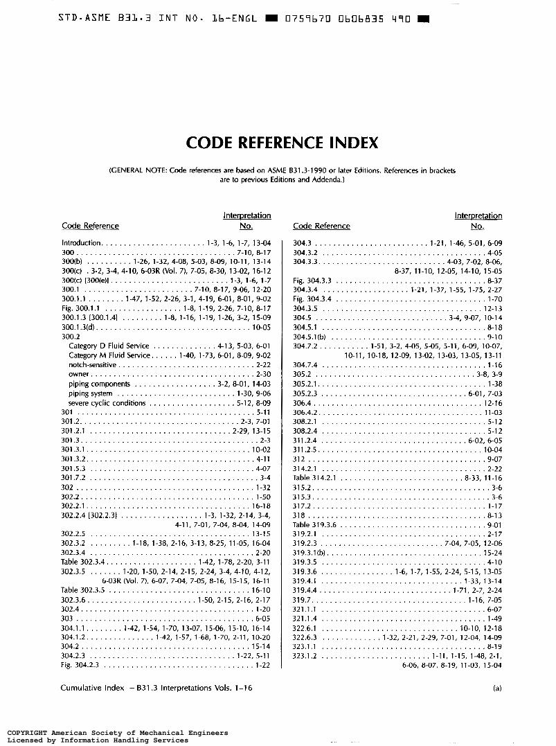
CODE REFERENCE INDEX
(GENERAL NOTE: Code references are based on ASME 831.3-1990 or later Editions . References in brackets are to prcvious Editions and Addenda.)
COPYRIGHT American Society of Mechanical EngineersLicensed by Information Handling ServicesCOPYRIGHT American Society of Mechanical EngineersLicensed by Information Handling Services
Cumulative Index - 631.3 lntcrprctations Vols . 1-1 7
~ ~~ ... -~ COPYRIGHT American Society of Mechanical EngineersLicensed by Information Handling ServicesCOPYRIGHT American Society of Mechanical EngineersLicensed by Information Handling Services
Appendix E [Appendix KI ...................... 1.44. 5-10 Appendix F [F323.2] ............................... 1-29 Appendix G ...................................... 5-12 Appendix H ................................ 8.06. 11-10 Appendix J ........................ 1.28. 1.54. 1.75. 5-04 Appendix M ................................. 6.01. 8-09 Appendix V ..................................... 17-1 7 Appendix X. X3.1.3 ............................... 12-23 Appendix X. X3.2.2 ............................... 13-09 Appendix X. X302.2.3 ............................. 15-22 Case 137 .......................................... 3-1 Case 141 ......................................... 1-51
Cumulative Index . B31.3 Interpretations Vols . 1-17
COPYRIGHT American Society of Mechanical EngineersLicensed by Information Handling ServicesCOPYRIGHT American Society of Mechanical EngineersLicensed by Information Handling Services
Allowable Stresses ................................. 4-1 2 bases for . . . . . . . . . . . . . 1.18. 3.13. 8-1 l. 8.25. 10.13. 15-01 for ASTM A 312 .................................. 1-29 for ASTM A 351 ................................. 11-13 for ASTM A 387 .................................. 8-25 for ASTM A 570 .................................. 1-38 for ASTM A 587 .................................. 1-13 for ASTM A 671 .................................. 1-48 for ASTM B 464 .................................. 8-11 for austenitic stainless steels ......................... 3-13
Alterations of Piping .............................. 13-04
Alternative Tests .......................... see Leak Tests
Cast Irons specific requirements .............................. 10-01
Category D Fluid Service alternative pressure test for .......................... 1-36 limitations ................................... 4-1 3. 5-03 radiographic examination ........................... 8-38
Category M Fluid Service clarification of term ........................... 1.73. 9-02 double contained piping ............................ 8-35 leak test ......................................... 6-08 liquid oxygen ..................................... 8-09 requirements ........................... 8.35. 9.02. 12-1 5 tubing size limitations .............................. 2-13 ''very small quantity" ............................... 1-40
oil heating system ................................. 4-19
Unlisted and Valves)
(e)
COPYRIGHT American Society of Mechanical EngineersLicensed by Information Handling ServicesCOPYRIGHT American Society of Mechanical EngineersLicensed by Information Handling Services
+; '
Subject ' Interpretation No .
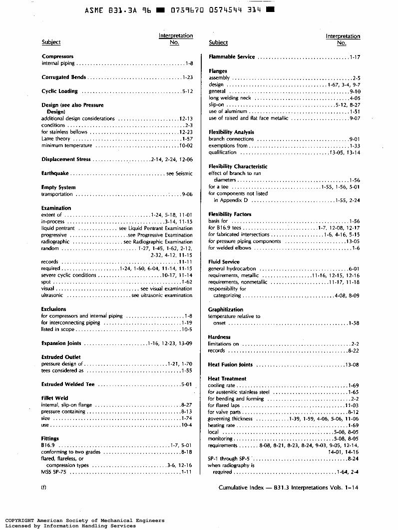
I Compressors internal piping ..................................... 1-8
Exclusions for compressors and internal piping ................... 1-8 for interconnecting piping. ........................... 1-19 listed in scope .................................... 10-5
Flammable Service ................................. 1-17
Flanges assembly .......................................... 2-5 design ................................... 1-67, 3-4, 9-7 general .......................................... 9-10 long welding neck ................................. 4-05 slip-on ...................................... 5-12. 8-27 use of aluminum .................................. 1-51 use of raised and flat face metallic ................... 9-07
Flexibility Analysis branch connections ................................ 9-01 exemptions from .................................. 1-33 qualification ............................... 13-05, 13-14 thermal expansion data ............................ 15-24
Flexibility Characteristic effect of branch to run diameters .................... 1-56 for a tee ............................... 1-55, 1-56, 5-01 for components not lkted in Appendix D ........ 1-55, 2-24
Flexibility Factors basis for ......................................... 1-56 for B16-9 tee .......................... 1-7, 12-08, 12-17 for fabricated intersections ................. 1-6, 4-16, 5-15 for pressure piping components ..................... 13-05 for welded elbows .................................. 1-6
Heat Treatment cooling rate ...................................... 1-69 for austenitic stainless steel ......................... 1-65 for bending and forming ............................. 2-2 for flared laps .................................... 11-03 for valve parts .................................... 8-12 governing thickness . . . . . . . . . . 1-39, 1-59, 4-06, 5-06, 11-06
Cumulative Index - B31.3 Interpretations Vols . 1-1 7
COPYRIGHT American Society of Mechanical EngineersLicensed by Information Handling ServicesCOPYRIGHT American Society of Mechanical EngineersLicensed by Information Handling Services
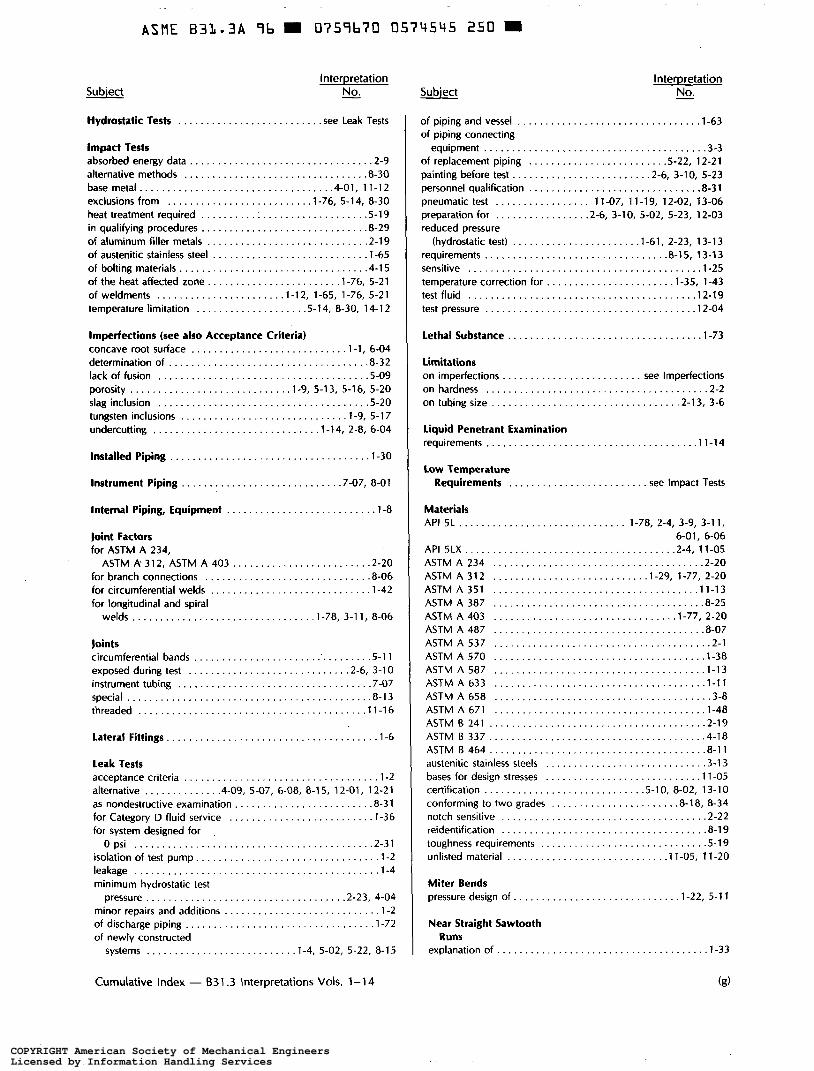
Limitations on hardness ....................................... 2-2 on imperfections ....................... see Imperfections on tubing size ................................ 2.13. 3-6
Low Temperature Requirements ........... s e e Impact Tests
Materials API 5L ................... 1.78. 2.4. 3.9. 3.11. 6.01. 6-06 API SLX ..................................... 2.4. 11-05 ASTM A 234 ..................................... 2-20 ASTM A 312 ........................... 1.29. 1.77. 2-20 ASTM A 351 .................................... 11-13 ASTM A 387 ..................................... 8-25 ASTM A 403 ................................ 1.77. 2-20 ASTM A 487 ..................................... 8-07 ASTM A 537 ...................................... 2-1 ASTM A 570 ..................................... 1-38 ASTM A 587 ..................................... 1-13 ASTM A 633 ..................................... 1-11 ASTM A 658 ...................................... 3-8 ASTM A 671 . . . . . . . . . . . . . . . . . . . . . . . . . . . . . . . . . . . . . 1-48 ASTM B 241 ..................................... 2-19 ASTM B 337 ..................................... 4-18 ASTM B 464 ..................................... 8-11 austenitic stainless steels ............................ 3-13
(g)
COPYRIGHT American Society of Mechanical EngineersLicensed by Information Handling ServicesCOPYRIGHT American Society of Mechanical EngineersLicensed by Information Handling Services
Published Specification .............................. 1-15
Radiographic Examination 1000/0 ............................................ 5-09 as supplementary examination ....................... 8-38 random radiography ..... 1.27. 1.45. 1.62. 2.12. 2.32. 3-12
Cumulative Index - 63l.3 Interpretations Vols . 1-1 7
COPYRIGHT American Society of Mechanical EngineersLicensed by Information Handling ServicesCOPYRIGHT American Society of Mechanical EngineersLicensed by Information Handling Services
Subject Interpretation No .
Radiographic Examination (Cont'd) rcrords .......................................... 1-1 O requirements . . . . . . . . . . . . . . . . . . . 6-04. 11.01. 11 .05. 12-03 selcution of welds for examination . . . . . . . . . . . . . . . . . . . 2-25 s p o t radiography ............................. 1.62. 3-12 when PWHT is required ........................ 1.64. 2-4
Records certiiication ............................ 5.10. 8.02. 10-03 for radiographic examination ........................ 1-1 O of examinations .................................. 1 1-1 1 of hardness tests .................................. 8-22 retention of ....................................... 1-10
Reinforcement. Branch attachment weld .............................. 4.03. 7-08 clarification of terms ......................... 1.37. 11-10 limits of ..................................... 2.27. 9-04
Repairs to welds ......................................... 2-18
Responsibility designer ......................................... 10-11 rights of owner's insprrtion .................. 10.03. 17-1 5
COPYRIGHT American Society of Mechanical EngineersLicensed by Information Handling ServicesCOPYRIGHT American Society of Mechanical EngineersLicensed by Information Handling Services
Sub’jsct Interpretation No.
1 Washers, Use of ................................... .,2-5
Cumulative Index - 831.3. IMerpretations Vols. 1-1 7
COPYRIGHT American Society of Mechanical EngineersLicensed by Information Handling ServicesCOPYRIGHT American Society of Mechanical EngineersLicensed by Information Handling Services
ASME B31.3
INTERPRETATIONS NO. 16
Replies to Technical Inquiries April 1, 1997, Through March 31, 1998
General Information
It has been agreed to publish interpretations issued by the B31 Committee concerning B31.3 as part of the update service to the Code. The interpretations have been assigned numbers in chronological order. Each interpretation applies to the Edition or Addenda stated in the interpretation, or if none is stated, to the Edition or Addenda in effect on the date of issuance of the interpretation. Subsequent revisions to the Code may have superseded the reply.
These replies are taken verbatim from the original letters, except for a few typographical and editorial corrections made for the purpose of improved clarity. In some instances, a review of the interpretation revealed a need for corrections of a technical nature. In these cases, a revised reply bearing the original interpretation number with the suffix R is presented.
ASME procedures provide for reconsideration of these interpretations when or if additional information is available which the inquirer believes might affect the interpretation. Further, persons aggrieved by an interpretation may appeal to the cognizant ASME committee or subcommittee. As stated in the Statement of Policy in the Code documents, ASME does not “approve,” “certify,” “rate,” or “endorse” any item, construction, proprietary device, or activity.
For detailed instructions on preparation of technical inquiries to the B3 I Committee, refer to Appendix Z.
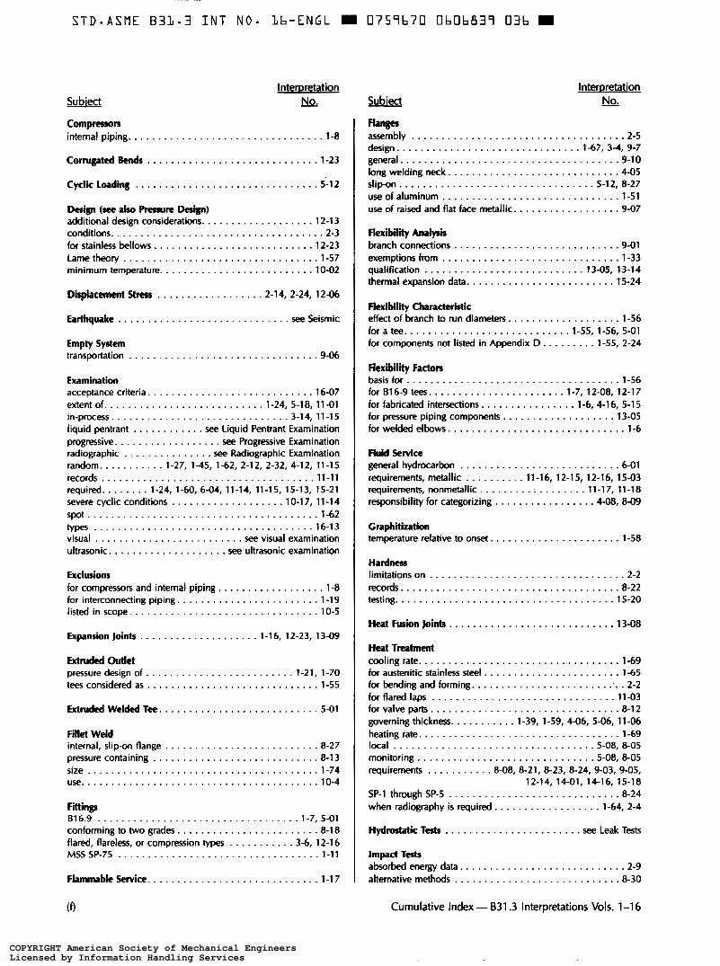
Code Reference and Subject Indexes
Code Reference and Subject Indexes have been prepared to assist the user in locating interpretations by location or by subject matter in the Code. They cover interpretations issued from Volume 1 up to and including the present volume, and will be updated with each volume.
185
COPYRIGHT American Society of Mechanical EngineersLicensed by Information Handling ServicesCOPYRIGHT American Society of Mechanical EngineersLicensed by Information Handling Services
B31.3
Subject . Para . 300(c)(3). Intent of the Code ............................................ Para . 302.2.1, Prssure-Temperature Design Criteria - Listed Components
Having Established Ratings ............................................... Para . 302.3.2, Limits of Calculated Stresses Due to Sustained Loads
and Displacement Strains ................................................. Para . 302.3.5, Limits of Calculated Stresses Due to Sustained Loads and
Displacement Strains ..................................................... Para . 304.1.1, Pressure Design of Components .................................. Para . 328.5.2. Welding Requirements - Fillet and Socket Welds .................. Para . 33 I . 1.6, Temperature Verification ........................................ Para . 332.2.2(a), Bending Temperature ........................................ Para . 341.3.4, Progressive Examination ........................................ Para . 341.3.4, Progressive Examination ........................................ Para . 341.3.4, Progressive Examination ........................................ Para.344,TypesofExamination ............................................. Para . 345, Leak Testing .................................................... Table 302.3.5, Stress-Range Reduction Factors .................................. Table 323.2.2, Minimum Temperatures Without Impact Testing for Carbon
SteelMaterials .......................................................... Table 341.3.2A, Examination Acceptance Criteria ............................... Flanged Ball Valves ....................................................... Tapered Pipe Thread Joints .................................................. Tubing in Category M Fluid Service ..........................................
COPYRIGHT American Society of Mechanical EngineersLicensed by Information Handling ServicesCOPYRIGHT American Society of Mechanical EngineersLicensed by Information Handling Services
~
STDmASME B3L.3 I N T N O - Lb-ENGL m 0757b70 O b O b 8 2 8 250 m
831.3 Interpretations No. 16 14-12R, 16-01, 16-02
Interpretation: 14-12R
Subject: ASME B31.3-1993 Edition, Table 323.2.2, Minimum Temperatures Without Impact Testing for Carbon Steel Materials
Date Issued: November 20, 1995
File: 631-95-018
Question: Does ASME 831.3-1993 Edition require impact testing of ASTM A 403 WP304W. B16.9 fittings manufactured from A 312 welded TP304 pipe without the use of weld metal deposits and used at design temperatures of -425°F or above.
Question: In accordance with ASME B31.3-1996 Edition, para. 341.3.4, Progressive Examination, if a defective weld is repaired, found defective again, repaired a second time and again found to be defective, is it necessary to examine two additional items for each failed repair?
Reply: No. See para. 341.3.3.
Interpretation: 16-02
Subject: ASME B3 I .3-1993 Edition, Para. 341.3.4, Progressive Examination
Date Issued: May 20, 1997
File: B3 1-96-054
Question ( I ) : In accordance with ASME B3 1.3-1993 Edition, Table 341.3.2A and para. 341.3.4, when the engineering design specifies more stringent acceptance criteria for normal fluid service, do the requirements of para. 34 I .3.4, Progressive Examination, still apply?
Reply ( I ) : Yes.
Question (2): In accordance with ASME B3 I .3- 1993 Edition, for normal fluid service, when a particular one hundred welds constitute a designated lot, welder “ A completes three welds and two are radiographed to acceptance, and welder “B” completes ninety-seven welds and five are radiographed to acceptance, do all welds in the lot, after visual and leak tests, meet the requirements of the Code?
Reply (2): Yes. provided no other welds in the designated lot were examined showing unacceptabel defects.
189
COPYRIGHT American Society of Mechanical EngineersLicensed by Information Handling ServicesCOPYRIGHT American Society of Mechanical EngineersLicensed by Information Handling Services
Question (1): In accordance with ASME B31.3-1996 Edition, para. 345.1(b), with a system design pressure of 150 psig at 200"F, and where a hydrostatic pressure test is impractical, does a pneumatic test at 150 psig or 110% of design pressure, whichever is less, satisfy the requirements of the Code?
Reply (1): No. See para. 345.5.4.
Question (2): In accordance with ASME B31.3-1996 Edition, under the above conditions, would testing in accordance with para. 345.9 be required?
Reply (2): No. Use of the alternative leak test is permitted only if the conditions of para. 345.1 (c) are met.
Interpretation: 16-04
Subject: ASME B3 I .3a- 1996 Addenda, Para. 302.3.2, Limits of Calculated Stresses Due to Sustained Loads and Displacement Strains
Date Issued: May 20, 1997
File: B3 1-96-057
Question ( I ) : In accordance with ASME B31.3a-1996 Addenda, para. 302.3.5, shall the longitudinal sustained stresses, S,, be evaluated in the installed and all operating positions of the pipe relative to its supports and restraints?
Reply (1): Yes.
Question (2): In accordance with ASME B31.3a-1996 Addenda, para. 302.3.5, is there an allowable operating stress for the combination of longitudinal sustained stresses and displacement stresses, not displacement stress ranges?
Reply (2): No. See para. 319.2.3.
I90
COPYRIGHT American Society of Mechanical EngineersLicensed by Information Handling ServicesCOPYRIGHT American Society of Mechanical EngineersLicensed by Information Handling Services
Question ( I ) : A welder’s production welds experience some rejections. The welder is retained and requalified. In accordance with ASME B31.3-1996 Edition, para. 341.3.4, Progressive Examination, does the Code require more stringent examination of this welders welds?
Reply (1): No.
Question (2): In accordance with ASME B3 I .3-1996 Edition, para. 341.3.4, can the two additional joints examined after a defective joint is found to be counted as part of the 5% random radiography requirement?
Question: In accordance with ASME B31.3-1996 Edition, para. 328.5.2 and Fig. 328.5.2c, what is the minimum gap acceptable in a socket-welded joint after welding?
Reply: The in. approximate gap shown in Fig. 328.5.2~ is “before welding.” The Code does not provide a gap dimension after welding.
Question: In accordance with ASME B3 1.3- 1993 Edition, Table 34 I .3.2A, in the radiographic examination of girth and miter groove welds, can a densitometer be used to evaluate root concavity?
Reply: The Code does not address the use of a densitometer for this purpose.
COPYRIGHT American Society of Mechanical EngineersLicensed by Information Handling ServicesCOPYRIGHT American Society of Mechanical EngineersLicensed by Information Handling Services
16-08,16-09,16-10
Interpretation: 16-08
Subject: ASME B3 I .3- I996 Edition, Para. 332.2.2(a), Bending Temperature
Date Issued: May 20, 1997
File: B3 1-97-001
831.3 Interpretations No. 16
Question: In accordance with ASME B3 1.3-1996 Edition, paras. 332.2.2(a) and (b), are the transformation ranges used in B3 1.3 considered to be the lower critical temperatures in ASME B3 1.1-1995 Edition, para. 129.3.1?
Reply: No.
Interpretation: 16-09
Subject: ASME B3 1.3a- 1996 Addenda, Para. 33 l. 1.6, Temperature Verification
Date Issued: May 20, 1997
File: B3 1-97-0 13
Question: In accordance with ASME B3 1.3a-1996 Addenda, para. 33 l . 1.6, can a thermocouple be laid on a part being heat treated as opposed to being attached?
Reply: The Code requires only that temperature be checked by thermocouple, pyrometers, or other suitable methods to ensure that WPS requirements are met. It does not otherwise address positioning or attachment of thermocouples, except for a permissive statement in para. 330.1.3(b) allowing attachment by capacitor discharge method without procedure and performance qualifications.
Question ( I ) : In accordance with ASME B31.3a-1996 Addenda, does the stress range reduction factor,
Reply ( I ) : No, except see para. 3 19.3.4(b).
f, as listed in Table 302.3.5 and provided in equation ( I c) depend on the material of construction?
Question (2): In accordance with ASME B3 I .3a- 1996 Addenda, Appendix D, do the stress intensification factors, ii and i,, depend on the material of construction?
Reply (2): No.
192
COPYRIGHT American Society of Mechanical EngineersLicensed by Information Handling ServicesCOPYRIGHT American Society of Mechanical EngineersLicensed by Information Handling Services
B31.3 Interpretations No. 16 16-11, 16-12, 16-13
Interpretation: 16-1 1
Subject: ASME B31.3a-1996 Addenda, Para. 302.3.5, Limits of Calculated Stresses Due to Sustained Loads and Displacement Strains
Date Issued: November 10, 1997
File: B3 1-97-024
Question (L): In accordance with ASME B3 1.3a- 1996 Addenda, para. 302.3.5, is the stress range reduction factor independent of the material of construction?
Reply (1): Yes; however, see para. 3 19.3.4(b).
Question (2): In accordance with ASME B3 1.3a- 1996 Addenda, are the stress intensification factors listed in Appendix D independent of the material of construction?
Reply: Yes; however, see para. 319.3.4(b).
Interpretation: 16-12
Subject: ASME B3 1.3a-1996 Addenda, Para. 300(c)(3), Intent of the Code
Date Issued: November 10, 1997
File: B3 1 -97-026B
Question (1): May a piping designer use para. 300(c)(3) of ASME B31.3a-1996 Addenda and apply a more rigorous analysis to qualify the design and acceptance criteria of piping where the Code requirements employ a simplified approach?
Reply (1): Yes, if the designer can demonstrate the validity of the approach to the owner.
Question (2): In accordance with ASME B3 1.3-1 996 Edition, does a piping system that has been designed in accordance with the Code but not fabricated or assembled as specified by the engineering design, comply with the Code if a more rigorous analysis proves it suitable for the service intended?
Reply (2): No. See para. 300.2, Definitions - Assembly and Erection. Also, see para. 341.3.2.
Interpretation: 16-13
Subject: ASME B3 1.3a-1996 Addenda, Para. 344, Types of Examination
Date Issued: November 10, 1997
File: B3 1-97-028
Question: In accordance with ASME B3 1.3a- 1996 Addenda, para. 344, does the Code contain instruction or restrictions regarding the design of a designated lot of piping?
Reply: No, other chan the definition in Note 2 of para. 344.1.3.
193
COPYRIGHT American Society of Mechanical EngineersLicensed by Information Handling ServicesCOPYRIGHT American Society of Mechanical EngineersLicensed by Information Handling Services
S T D - A S M E 831.3 INT N O . Lb-ENGL D 0759b70 ObOb833 h l 8
16-14, 16-15, 16-16 831.3 Interpretations No. 16
Interpretation: 16-14
Subject: ASME B3 1.3a- I996 Addenda, Para. 304. I . 1, Pressure Design of Components
Date Issued: November IO, 1997
File: B3 1-97-029
Question: For subsea production systems where ASME B31.3 is required, can the internal design gage pressure, P, in paras. 304.1. I and 304. I .2 be interpreted as coincident internal design gage pressure minus external gage pressure?
Reply: Yes; however, when the coincident external gage pressure is greater than the internal gage pressure, the design shall be in accordance with para. 304.1.3.
Question: According to ASME 831.3-1996 Edition, are flanged ball valves where the ball is held in place by a threaded retainer plug in which the end of the plug forms some or all of the flange face prohibited from use in Category M Fluid Service?
Reply: No.
I94
COPYRIGHT American Society of Mechanical EngineersLicensed by Information Handling ServicesCOPYRIGHT American Society of Mechanical EngineersLicensed by Information Handling Services
~~
STDSASME B 3 1 - 3 INT NO. Lb-ENGL 0759670 ObOb834 554 H
B31.3 Interpretations No. 16
Interpretation: 16-17
Subject: ASME B31.3-1996 Edition, Tubing in Category M Fluid Service
Date Issued: September 3, 1997
File: B3 1-97-037
16-17, 16-18
Question: In accordance with ASME B3 I .3- 1996 Edition, is tubing with flared, flareless, and compression tubing joints prohibited for Category M fluid service in sizes larger than 16 mm (y8 in.) O. D. for piping other than instrumentation signal lines in contact with process fluids and process temperature-pressure conditions?
Reply: No. Also, see Interpretation 2- 13.
Interpretation: 16-18
Subject: ASME B3 I .3a- 1996 Addenda, Para. 302.2.1, Pressure-Temperature Design Criteria - Listed Components Having Established Ratings
Date Issued: September 3, 1997
File: B3 1-97-038
Question: When selecting a flange on the basis of pressure-temperature rating given in ASME B 16.5, in accordance with ASME B3 1.3a- 1996 Addenda, para. 302.2. I, is it required to consider any external forces and moments acting on the flange?
Reply: Yes. See para. 303.
I95
COPYRIGHT American Society of Mechanical EngineersLicensed by Information Handling ServicesCOPYRIGHT American Society of Mechanical EngineersLicensed by Information Handling Services
CODE REFERENCE INDEX (GENERAL NOTE: Code references are based on ASME 631.3-1 990 or later Editions . References in brackets
Cumulative Index . B31.3 Interpretations Vols . 1-1 6 (a)
COPYRIGHT American Society of Mechanical EngineersLicensed by Information Handling ServicesCOPYRIGHT American Society of Mechanical EngineersLicensed by Information Handling Services
Cumulative Index - B31.3 Interpretations Vols . 1-1 6
COPYRIGHT American Society of Mechanical EngineersLicensed by Information Handling ServicesCOPYRIGHT American Society of Mechanical EngineersLicensed by Information Handling Services
Cumulative Index . B31.3 Interpretations Vols . 1-1 6
COPYRIGHT American Society of Mechanical EngineersLicensed by Information Handling ServicesCOPYRIGHT American Society of Mechanical EngineersLicensed by Information Handling Services
Cumulative Index . B31.3 Interpretations Vols . 1-1 6 (e)
COPYRIGHT American Society of Mechanical EngineersLicensed by Information Handling ServicesCOPYRIGHT American Society of Mechanical EngineersLicensed by Information Handling Services
S T D - A S M E B3L-3 I N T NO . L b - E N G L W 0 7 5 9 b 7 0 OhOb839 03b m
Fkxib i l i Analysis branch connections ............................ 9.01 exemptions from .............................. 1.33 qualification ........................... 13.05, 13-14 thermal expansion data ......................... 15-24
Flexibility Characteristic effect of branch to run diameters . . . . . . . . . . . . . . . . . . . 1-56 for a tee . . . . . . . . . . . . . . . . . . . . . . . . . . . . 1.55.1.56. 5.01 for components not listed in Appendix D . . . . . . . . . 1.55. 2-24
Cumulative Index . B31.3 Interpretations Vols . 1-1 6
COPYRIGHT American Society of Mechanical EngineersLicensed by Information Handling ServicesCOPYRIGHT American Society of Mechanical EngineersLicensed by Information Handling Services
Cumulative Index . B31.3 Interpretations Vols . 1-1 6
COPYRIGHT American Society of Mechanical EngineersLicensed by Information Handling ServicesCOPYRIGHT American Society of Mechanical EngineersLicensed by Information Handling Services
Cumulative Index - 631.3 Interpretations Vols . 1-1 6
COPYRIGHT American Society of Mechanical EngineersLicensed by Information Handling ServicesCOPYRIGHT American Society of Mechanical EngineersLicensed by Information Handling Services
~~~
STD-ASME 831.3 I N T N O * Lb-ENGL m 0759b7U UbUb8112 b20 m
Cumulative Index . B31.3 Interpretations Vols . 1-1 6
COPYRIGHT American Society of Mechanical EngineersLicensed by Information Handling ServicesCOPYRIGHT American Society of Mechanical EngineersLicensed by Information Handling Services
ASME B3 1.3 INTERPRETATIONS NO. 15
Replies to Technical Inquiries April 1, 1996, Through March 31, 1997
General Information
It has been agreed to publish interpretations issued by the B31 Committee concerning B31.3 as part of the update service to the Code. The interpretations have been assigned numbers in chronological order. Each interpretation applies to the Edition or Addenda stated in the interpretation, or if none is stated, to the Edition or Addenda in effect on the date of issuance of the interpretation. Subsequent revisions to the Code may have superseded the reply. These interpretations are not part of the Code or its Addenda.
These replies are taken verbatim from the original letters, except for a few typographical and editorial corrections made for the purpose of improved clarity. In some instances, a review of the interpretation revealed a need for corrections of a technical nature. In these cases, a revised reply bearing the original interpretation number with the suffix R is presented.
ASME procedures provide for reconsideration of these interpretations when or if additional infor- mation is available which the inquirer believes might affect the interpretation. Further, persons aggrieved by an interpretation may appeal to the cognizant ASME committee or subcommittee. As stated in the Statement of Policy in the Code documents, ASME does not “approve,” “certify,” “rate,” or “endorse” any item, construction, proprietary device, or activity.
For detailed instructions on preparation of technical inquiries to the B31 Committee, refer to Appendix 2.
Code Reference and Subject indexes
Code Reference and Subject Indexes have been prepared to assist the user in locating interpretations by location or by subject matter in the Code. They cover interpretations issued from Volume 1 up to and including the present volume, and will be updated with each volume.
169
COPYRIGHT American Society of Mechanical EngineersLicensed by Information Handling ServicesCOPYRIGHT American Society of Mechanical EngineersLicensed by Information Handling Services
COPYRIGHT American Society of Mechanical EngineersLicensed by Information Handling ServicesCOPYRIGHT American Society of Mechanical EngineersLicensed by Information Handling Services
S T D - A S M E B3L.3 I N T N O - 1 5 - E N G L m 0 7 5 7 b 7 0 0 5 8 4 0 3 2 T7b
Question (1): Are the material requirements of ASME SA-106 the same as ASTM A 106?
Reply (2): Yes.
Question (2): When doing an ASME B3 1.3 system stress evaluation, what allowable stresses are used for ASTM A 106 or ASME SA-106?
Reply (2): Those listed in ASME B31.3~-1995 Addenda, Table A-1 for ASTM A 106.
Interpretation: 15-02
Subject: ASME B31.3~-1995 Addenda, Para. 345.9.1(a), Examination of Welds
Date Issued: May 21, 1996
File: B3 1-95-045
Question: In accordance with ASME B31.3~-1995 Addenda, is it permissible to perform magnetic particle examination of a circumferential weld in lieu of radiography as specified in para. 345.9.1(a)?
Reply: No.
173
COPYRIGHT American Society of Mechanical EngineersLicensed by Information Handling ServicesCOPYRIGHT American Society of Mechanical EngineersLicensed by Information Handling Services
15-03, 15-04 B3 1.3 Interpretations No. 1 5
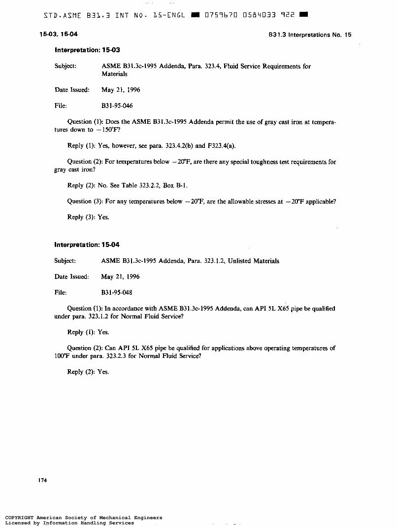
Interpretation: 15-03
Subject: ASME B31.3~-1995 Addenda, Para. 323.4, Fluid Service Requirements for Materials
Date Issued: May 2 1 , 1996
File: B3 1-95-046
Question (1): Does the ASME B31.3~-1995 Addenda permit the use of gray cast iron at tempera- tures down to - 150°F
Reply (1): Yes, however, see para. 323.4.2(b) and F323.4(a).
Question (2): For temperatures below - 20"F, are there any special toughness test requirements for gray cast iron?
Reply (2): No. See Table 323.2.2, Box B-l.
Question (3): For any temperatures below -20°F, are the allowable stresses at -20°F applicable?
Question (1): In accordance with ASME B3 1.3~-1995 Addenda, can API 5L X65 pipe be qualified under para. 323.1.2 for Normal Fluid Service?
Reply (1): Yes.
Question (2): Can API 5L X65 pipe be qualified for applications above operating temperatures of 100°F under para. 323.2.3 for Normal Fluid Service?
Reply (2): Yes.
174
COPYRIGHT American Society of Mechanical EngineersLicensed by Information Handling ServicesCOPYRIGHT American Society of Mechanical EngineersLicensed by Information Handling Services
~~
S T D - A S M E B 3 1 - 3 INT N O - 1 5 - E N G L m 0 7 5 7 b 7 0 0 5 8 4 0 3 4 Ab7 m
Question: In accordance with ASME B31.3~-1995 Addenda, para. 304.3.3, is it permissible to multiply the required area replacement in Eq. (6) by factor F from ASME Section VIII, Division 1, 1995 Edition, Fig. UG-37? The nozzle is welded on a cylindrical header as per Fig. UW-16.1 sketch (a).
Reply: No, except as provided in para. 300(c)(3) considering the design conditions of para. 301 and design criteria of para. 302.
Question: In accordance with ASME B31.3~-1995 Addenda, para. 335.1.1(c), prior to bolting up a flanged joint, may the flange faces be out of alignment from the design plane by more than 1/16 in./ft (0.5%), provided the misalignment is considered in the design of the flanged assembly and attached piping in accordance with para. 300(c)(3)?
Reply: Yes.
175
COPYRIGHT American Society of Mechanical EngineersLicensed by Information Handling ServicesCOPYRIGHT American Society of Mechanical EngineersLicensed by Information Handling Services
15-08, 15-09, 15-10 B 3 1.3 Interpretations No. 15
Question: In accordance with ASME B3 1.3~-1995 Addenda, may the fillet weld shown in Fig. 328.5.2B Sketch (3) (socket welding flange) be repositioned to the inside of the pipe?
Question: May the internal pressure design thickness t be computed in accordance with the provi- sions of ASME B31.3~-1995 Addenda, paras. 304.1.1 and 304.1.2 when t is greater than or equal to D / 6 and P/SE > 0.385?
Reply: Yes. However, it is the responsibility of the designer to provide the special consideration required in para. 304.1.2(b). Alternatively, as an option to the owner, the design may be in accordance with Chapter IX.
176
COPYRIGHT American Society of Mechanical EngineersLicensed by Information Handling ServicesCOPYRIGHT American Society of Mechanical EngineersLicensed by Information Handling Services
B 3 1.3 Interpretations No. 15 15-11, 15-12
Interpretation: 15-1 1
Subject: ASME B31.3~-1995 Addenda, Table 323.2.2, Minimum Temperature Without Impact Testing for Carbon Steel Materials
Date Issued: May 21, 1996
File: B31-96-014
Question (1): Does the assigned curve in the second sentence of Box B-3, Table 323.2.2, ASME B31.3~-1995 Addenda refer to the curve assignment from Table A-l?
Reply (1): Yes.
Question (2): If the material has been heat treated per Note (2) or (3), Fig. 323.2.2, is further heat treatment or impact testing of the base metal required for use below the original assigned curve, but above the reassigned curve?
Question (1): In accordance with ASME B3 1.3~-1995 Addenda, when making blind flanges of carbon steel plate materials which have a Fig. 323.2.2 Curve assignment in Table A-1, is the thickness of the finished blind considered the nominal thickness when using Fig. 323.2.2 to establish the need for impact testing?
Reply (1): Yes.
Question (2): For carbon steel materials with a letter designation in the Min. Temp. column of Table A-1, can flanges manufactured in accordance with ASME B16.5 be used at temperatures down to - 10°F without impact testing regardless of thickness?
Reply (2): No, the requirements of para. 323.2.2 apply.
COPYRIGHT American Society of Mechanical EngineersLicensed by Information Handling ServicesCOPYRIGHT American Society of Mechanical EngineersLicensed by Information Handling Services
Question: If a fabricated valve meets all the requirements of ASME B16.34, does ASME B3 1 .3~- 1995 Addenda require that nondestructive examination in accordance with ASME B31.3 also be per- formed on the valve?
Reply: No, see also Interpretation 12-12.
Interpretation: 15-1 4
Subject: ASME B3 1.3~-1995 Addenda, Para. 304.2, Curved and Mitered Segments of Pipe
Date Issued: May 21, 1996
File: B3 1-96-0 18
Question (1): In accordance with ASME B31.3~-1995 Addenda, para. 304.2.1, can the minimum required thickness c , of a bend, after bending, be determined by taking in consideration of lower (pressure) stresses on the outside of a bend (and higher pressure stresses on the inside of the bend) than on a straight pipe with identical wall thickness?
Reply (1): No, except as provided in para. 300(c)(3).
Question (2): In accordance with ASME B3 1.3~- 1995 Addenda, Chapter IX (High Pressure Piping), can the minimum required thickness t , of a bend, after bending, be determined by taking into considera- tion lower stresses on the outside of a bend (and higher stresses on the inside of the bend) than on a straight pipe with identical wall thickness?
Reply (2): No, except as provided in para. 300(c)(3).
178
COPYRIGHT American Society of Mechanical EngineersLicensed by Information Handling ServicesCOPYRIGHT American Society of Mechanical EngineersLicensed by Information Handling Services
S T D - A S M E B 3 1 . 3 INT N O - 1 5 - E N G L m 0 7 5 7 6 7 0 0 5 8 4 0 3 8 4 0 4
B3 1.3 Interpretations No. 15 15-1 5, 15-1 6
Interpretation: 15-1 5
Subject: ASME B31.3~-1995 Addenda, Para. 302.3.5, Limits of Calculated Stresses due to Sustained Loads and Displacement Strains
Date Issued: May 2 1, 1996
File: B3 1-96-020
Quation (1): What is the definition of sustained loadings as intended in ASME B3 1.3~-1995 Addenda, para. 302.3.5(c)?
Reply (1): The Code does not offer for sustained loadings other than in the referenced paragraph. Sustained loads do not typically include forces resulting from applied displacements such as restrained thermal growth. See para. 319.2.3.
Question (2): When flanges are subjected to external forces and moments, is it permissible to calculate the stresses in the flange due to these forces and moments using BPV Code, Section VIII, Division 1, Appendix 2, and using the equivalent pressure calculated from these forces and moments?
Reply (2): The Code does not provide specific design formulas for the design of flange joints subjected to applied external forces and moments except as provided in para. 300(c)(3). However, external forces and moments shall be considered in design. See paras. 3 19. l. 1 and 32 l. l . l .
Interpretation: 15-1 6
Subject: ASME B31.3~-1995 Addenda, Table 323.2.2, Minimum Temperature Without Impact Testing for Carbon Steel Materials
Date Issued: May 2 1, 1996
File: B31-96-021
Question (1): Does the assigned curve in the second sentence of Box B-3, Table 323.2.2, ASME B3 1.3~-1995 Addenda refer to the curve assignment from Table A-l?
Reply (1): Yes.
Question (2): If the material has been heat treated per Notes (2) or (3), Fig. 323.2.2, is further heat treatment or impact testing of the base metal required for use below the original assigned curve, but above the reassigned curve?
Reply (2): No.
179
COPYRIGHT American Society of Mechanical EngineersLicensed by Information Handling ServicesCOPYRIGHT American Society of Mechanical EngineersLicensed by Information Handling Services
15-1 7, 15-1 8 B3 1.3 Interpretations No. 15
Interpretation: 15-1 7
Subject: ASME B31.3-1990 Edition, Para. 332.4.2(a); Cold Bending and Forming
Date Issued: October 30, 1996
File: B3 1-96-034
Question: In accordance with ASME B31.3-1990 Edition, para. 332.4.2(a), cold bending and forming, can the elongation value for SA-106 B reported in the Certified Material Test Report be substituted for the specified basic minimum elongation in calculating the maximum fiber elongation?
Question (1): In accordance with ASMEB31.3c-1993 Addenda, Table 331.1.1 and para. 331.1.3(b), do socket welds and seal welds with P-No. 5 materials with a chromium content greater than 3% but less than lo%, a carbon content less than 0.15%, and a weld throat thickness of 0.5 in. or less require postweld heat treatment if matching filler material is used?
Reply (1): Yes, unless applicable provisions of para. 331.1.3(b) are met.
Question (2): In accordance with ASME B31.3~-1995 Addenda, Table 331.1.1 and para. 331.1.3(b), do socket welds and seal welds with P-No. 5 materials with a chromium content greater than 3% but less than lo%, a carbon content less than 0.15%, and a weld throat thickness of 0.5 in. or less require postweld heat treatment if a non-air-hardening filler metal is used?
Reply (2): No.
Question (3): In accordance with ASME B31.3~-1995 Addenda, Table 331.1.1 and paras. 331.1.3(b) and 33 1.1.7, if a non-air-hardenable filler is used, is the base metal HAZ required to be 241 maximum Brinell hardness for P-No. 5 materials with chromium content greater than 3% but less than lo%?
Reply (3): Yes, unless the applicable provisions of para. 331.3(b) are met.
Question (4): In accordance with ASME B31.3~-1995 Addenda, Table 331.1.1 and para. 331.1.3(b), do the requirements of para. 331.1.3(b) override the requirements of Table 331.1.1 relating to base metal group and/or the specified minimum tensile strength?
Reply (4): No, unless the applicable provisions of para. 331.1.3(b) are met.
COPYRIGHT American Society of Mechanical EngineersLicensed by Information Handling ServicesCOPYRIGHT American Society of Mechanical EngineersLicensed by Information Handling Services
B 3 1.3 Interpretations No. 15 15-1 9, 15-20
Interpretation: 15-1 9
Subject: ASME B31.3-1996 Edition, Para. 328.2.3, Performance Qualification by Others
Date Issued: October 30, 1996
File: B3 1-96-037
Question: In accordance with ASME B31.3-1996 Edition, para. 328.2.3, is it acceptable for an employer to accept a welder performance qualification previously conducted by an organization whose welder qualification program, with the exception of testing under the full supervision and control of the manufacturer, contractor, assembler, or installer, complies fully with the provisions of ASME Section IX?
Question: Does ASME B31.3-1993 Edition require P-No. 1 carbon steel welds, hot bends, and hot-formed components locally heat treated to be hardness tested?
Reply: No.
181
COPYRIGHT American Society of Mechanical EngineersLicensed by Information Handling ServicesCOPYRIGHT American Society of Mechanical EngineersLicensed by Information Handling Services
STDmASME B 3 1 . 3 I N T NO. I S - E N G L e U759b70 0584043 T T 7 U
1 5-2 1 B31.3 Interpretations No. 15
Interpretation: 15-21
Subject: ASME B31.3a-1993 Addenda, Paras. 342 and 344.2, Examination
Date Issued: October 30, 1996
File: B3 1-96" 1
Question (1): Does ASME B31.3a-1993 Addenda, paras. 342 and/or 344.2 require that personnel performing visual examinations required by paras. 341.4 and 344.7 be qualified and certified in accord- ance with SNT-TC- 1 A, Recommended Practice for Nondestructive Testing Personnel Qualification and Certification?
Reply (1): No.
Question (2): Does ASME B31.3a-1993 Addenda, paras. 342 and/or 344.2 require that personnel performing visual examinations required by paras. 341.4 and 344.7 be qualified and certified to AWS QCl, Standard for Qualification and Certification of Welding Inspectors?
Reply (2): No.
Question (3): Does ASME B31.3a-1993 Addenda, paras. 342 and 344.2 permit that the visual examinations required by paras. 341.4 and 344.7 be performed by personnel that (1) meet the physical requirements of ASME BPV Code, Section V, Article 9, (2) are competent to perform visual examination in accordance with the manufacturer's written procedures and (3) the employer certifies and makes available records of the examiner which show dates and results of qualifications?
Reply (3): Yes.
Question (4): Does ASME B31.3a-1993 Addenda, paras. 342 and 344.2 permit that the visual examinations required by paras. 341.4 and 344.7 be performed by personnel that (1) meet the physical requirements of ASME BPV Code Section C, Article 9, (2) have training and experience commensurate with the needs of the visual examinations required by paras. 341.4 and 344.7, (3) have demonstrated competence to perform the visual examinations using the employer's written procedures through written and practical testing administered by the employer, and (4) the employer certifies and makes available records of the examiner which show dates and results of qualification?
Reply (4): Yes.
182
COPYRIGHT American Society of Mechanical EngineersLicensed by Information Handling ServicesCOPYRIGHT American Society of Mechanical EngineersLicensed by Information Handling Services
STD.ASME B3L.3 I N T N O . L S - E N G L M 0 7 5 9 b 7 0 0 5 8 4 0 4 2 7 3 5 m
B3 1.3 Interpretations No. 15 15-22, 15-23, 15-24
Interpretation: 15-22
Subject: ASME B31.3-1996 Edition, Para. X302.2.3, Leak Test
Date Issued: October 30, 1996
File: B3 1-96-043
Question: In accordance with ASME B31.3-1996 Edition, para. X302.2.3, is a pneumatic leak check of an expansion joint at a test pressure of 110% of the design pressure, in accordance with para. 345.5, an acceptable test?
Question: In accordance with ASME B31.3-1996 Edition, when qualifying welding procedures which require impact testing, is the thickness range qualified to T/2 to T + Y4 in. rather than the range given in ASME Section IX, QW-403.10?
Reply: Yes, provided the criteria and thickness limits specified in ASME Section IX, para. QW- 403.10 are not exceeded. See ASME B31.3, Table 323.3.1, box A-5.
Interpretation: 15-24
Subject: ASME B31.3-1996 Edition, Para. 319.3.1(b), Thermal Expansion Data
Date Issued: October 30, 1996
File: B3 1-96-045
Question (1): In accordance with ASME B31.3-1996 Edition, para. 319.3.1(b), must all thermal conditions of a piping system be evaluated for end reactions on equipment?
Reply (1): Yes.
Question (2): Does ASME B31.3 provide specific allowable piping load limits for end reactions on equipment?
Reply (2): No.
183
COPYRIGHT American Society of Mechanical EngineersLicensed by Information Handling ServicesCOPYRIGHT American Society of Mechanical EngineersLicensed by Information Handling Services
Question: In accordance with ASME B31.3~-1995 Addenda, Para. 323.2.2 and Table 323.2.2, does P-No. 1 carbon steel subject to metal temperatures between -20°F and - 50°F with coincident pressure in excess of 25% of the maximum allowable design pressure require impact testing?
Reply: Yes, except as provided in Note ( 5 ) of Table 323.2.2.
Interpretation: 15-26
Subject: ASME B3 1.3-1996 Edition, Metallic Valves Lined with a Nonmetal
Date Issued: October 30, 1996
File: B3 1-96-049
Question (1): Does ASME B31.3-1993 Edition prohibit the use of a metallic valve lined with a nonmetal in Category M Fluid Service?
Reply (1): No.
Question (2): Does ASME B31.3-1993 Edition address a sensitive leak test for a metallic valve lined with a nonmetal?
Reply (2): No.
184
COPYRIGHT American Society of Mechanical EngineersLicensed by Information Handling ServicesCOPYRIGHT American Society of Mechanical EngineersLicensed by Information Handling Services
STDsASME B31-3 INT N O - 15 -ENGL m 0 7 5 7 b 7 0 0 5 8 4 0 4 q 708 m
CODE REFERENCE INDEX .
(GENERAL NOTE: Code references are based on ASME B31.3-1990 or later Editions . References in brackets are to previous Editions and Addenda.)
COPYRIGHT American Society of Mechanical EngineersLicensed by Information Handling ServicesCOPYRIGHT American Society of Mechanical EngineersLicensed by Information Handling Services
Cumulative Index . B31.3 Interpretations Vols . 1-1 5
COPYRIGHT American Society of Mechanical EngineersLicensed by Information Handling ServicesCOPYRIGHT American Society of Mechanical EngineersLicensed by Information Handling Services
STD-ASME B 3 4 . 3 I N T N O - 1 5 - E N G L II 0757b70 058404b 5 8 0 9
Cumulative Index . 631.3 Interpretations Vols . 1-1 5
COPYRIGHT American Society of Mechanical EngineersLicensed by Information Handling ServicesCOPYRIGHT American Society of Mechanical EngineersLicensed by Information Handling Services
Cumulative Index . 631.3 Interpretations Vols . 1-1 5
COPYRIGHT American Society of Mechanical EngineersLicensed by Information Handling ServicesCOPYRIGHT American Society of Mechanical EngineersLicensed by Information Handling Services
STD-ASME B 3 1 - 3 INT N O . 15-ENGL m
Subiect Interpretation
No . - in-line sensing devices ................................ 8.01 referenced standards .......................... . l-44, 5-1 O
Exclusions for compressors and internal piping .................... . l-8 for interconnecting piping ............................ 1.19 listed in scope ..................................... .1 0-5
Heat Treatment cooling rate ....................................... . l-69 for austenitic stainless steel .......................... . l-65 for bending and forming ...... for flared laps . . . . . . . . . . . . . . . for valve parts .............. governing thickness ......... heating rate ................ local ..................... monitoring .................
Cumulative Index . 63 1
........................ 2-2
...................... 11-03
....................... 8-12
. . l-39, 1.59. 4.06. 5-06. 11-06
....................... 1-69
. . . . . . . . . . . . . . . . . .5-08. 8-05
. . . . . . . . . . . . . . . . . .5.08. 8-05
. 3 Interpretations Vols . 1-1 5
COPYRIGHT American Society of Mechanical EngineersLicensed by Information Handling ServicesCOPYRIGHT American Society of Mechanical EngineersLicensed by Information Handling Services
Cumulative Index . B31.3 Interpretations Vols . 1-15
COPYRIGHT American Society of Mechanical EngineersLicensed by Information Handling ServicesCOPYRIGHT American Society of Mechanical EngineersLicensed by Information Handling Services
Records certification ............................ .5.10. 8.02. 10-03 of examinations ................................... 1 1-1 1 of hardness tests .................................... 8.22 for radiographic examination ......................... . 1-1 0 retention of ........................................ 1-10
Reinforcement. Branch attachment weld .............................. .4.03. 7-08 clarification of terms .......................... .1.37. 1 1-1 0 limits of ..................................... .2.27. 9-04
Cumulative Index . B3 1.3 Interpretations Vols . 1- 15
COPYRIGHT American Society of Mechanical EngineersLicensed by Information Handling ServicesCOPYRIGHT American Society of Mechanical EngineersLicensed by Information Handling Services
STD.ASME €332.3 I N T N O - 25-ENGL m 0759b70 0 5 8 4 0 5 3 7 4 8
COPYRIGHT American Society of Mechanical EngineersLicensed by Information Handling ServicesCOPYRIGHT American Society of Mechanical EngineersLicensed by Information Handling Services
ASME B31=3A 96 m 0759679 O574530 82T W
ASME B3 1.3 INTERPRETATIONS NO. 14
Replies to Technical Inquiries April 1, 1995, Through March 31, 1996
General Information
It has been agreed to publish interpretations issued by the B3 1 Committee concerning B3 1.3 as part of the update service to the Code. The interpretations have been assigned numbers in chronological order. Each interpretation applies to the Edition or Addenda stated in the interpretation, or if none is stated, to the Edition or Addenda in effect on the date of issuance of the interpretation. Subsequent revisions to the Code may have superseded the reply. These interpretations are not part of the Code or its Addenda.
These replies are taken verbatim from the original letters, except for a few typographical and editorial corrections made for the purpose of improved clarity. In some instances, a review of the interpretation revealed a need for corrections of a technical nature. In these cases, a revised reply bearing the original interpretation number with the suffix R is presented.
ASME procedures provide for reconsideration of these interpretations when or if additional infor- mation is available which the inquirer believes might affect the interpretation. Further, persons aggrieved by an interpretation may appeal to the cognizant ASME committee or subcommittee. As stated in the Statement of Policy in the Code documents, ASME does not “approve,” “certify,” “rate,” or “endorse” any item, construction, proprietary device, or activity.
For detailed instructions on preparation of technical inquiries to the B31 Committee, refer to Appendix 2.
Code Reference and Subject Indexes
Code Reference and Subject Indexes have been prepared to assist the user in locating interpretations by location or by subject matter in the Code. They cover interpretations issued from Volume 1 up to and including the present volume, and will be updated with each volume.
157
COPYRIGHT American Society of Mechanical EngineersLicensed by Information Handling ServicesCOPYRIGHT American Society of Mechanical EngineersLicensed by Information Handling Services
ASME 831.3A 96 0759b70 0574533 766 U
B31.3
Subject
Fig . 323.2.2, Minimum Temperatures Without Impact Testing for Carbon Steel Materials . . . . . Maximum Allowable External Loads ................................................. Para . 300.2 &finitions ............................................................. Para . 302.2.4, Design Criteria Allowances for Pressure and Temperature Variations. and Para . 322.6.3(c), Pressure Relieving Devices ................................................. Para . 304.3.3 Reinforcement of Welded Branch Connections .............................. Para . 328.2 Welding Qualifications ................................................... Para . 328.2.2(g), Procedure Qualification by Others ..................................... Para . 328.4.3, Preparation for Welding Alignment ...................................... Para . 331.1.3(b) and Table 331.1.1, Heat Treatment Requirements ......................... Para . 341.3.3 Defective Components and Workmanship ..................................
Para . A304.1.1 (a). Pressure Design of Nonmetallic Piping Components .................... Para . K304.1.2 Straight Pipe Under Internal Pressure ................................... Table 323.2.2, Minimum Temperatures Without Impact Testing for Carbon Steel Materials . . . .
Table 341.3.2A Acceptance Criteria for Welds .........................................
Table 341.3.2A Acceptance Criteria for Welds .........................................
Para . A304.1.1 (a). Pressure Design of Nonmetallic Piping Components ....................
COPYRIGHT American Society of Mechanical EngineersLicensed by Information Handling ServicesCOPYRIGHT American Society of Mechanical EngineersLicensed by Information Handling Services
Question (1): In accordance with ASME B3 1.3-1993 Edition, Addenda b, does the portion of para. 331.1.3@) which states “the thickness through the weld in any plane” refer to the weld thickness?
Reply (1): Yes.
Question (2): In accordance with ASME B31.3-1993 Edition, Addenda b, does the minimum material thickness stated in para. 331.1.3(b) refer to the requirements of Table 331.1.1?
Reply (2): Yes.
Question (3): In accordance with ASME B31.3-1993 Edition, Addenda b, can the BHN (Brinell Hardness Number) equivalent of tensile strength of material before PWHT be considered a minimum value?
Reply (3): The Code does not address BHN equivalent of tensile strength or minimum BHN.
161
COPYRIGHT American Society of Mechanical EngineersLicensed by Information Handling ServicesCOPYRIGHT American Society of Mechanical EngineersLicensed by Information Handling Services
~~
ASME B31.3A 96 m 0757670 0574533 539 m
14-02 B 3 1.3 Interpretations No. 14
Interpretation: 14-02
Subject: ASME B31.3b-1994 Addenda, Table 341.3.2A Acceptance Criteria for Welds
Date Issued: June 22, 1995
File: B3 1-95-001
Question (1): In accordance with ASME B31.3-1993 Edition, Addenda b, what does the notation “NA” for concave root surfaces for fillet welds in Table 341.3.2A mean?
Reply (1): This indicates that there is no acceptance criterion.
Question (2): In accordance with ASME B31.3-1993 Edition, Addenda b, does internal protrusion or suck up apply to fillet welds?
Reply (2): No; see Note (8) in Table 341.3.2A.
Question (3): Does ASME B31.3-1993 Edition, Addenda b, address the acceptance criteria for root surface concavity of fillet welds?
Reply (3): No.
Question (4): In accordance with ASME B31.3-1993 Edition, Addenda b, does melt-through of a pressure boundary with a fillet weld constitute a violation of the Code?
Reply (4): The Code does not address this subject.
162
COPYRIGHT American Society of Mechanical EngineersLicensed by Information Handling ServicesCOPYRIGHT American Society of Mechanical EngineersLicensed by Information Handling Services
Question (1): In accordance with ASME B3 1.3-1993 Edition, Addenda b, para. 300.2, is weld considered to be a piping component?
Reply (1): No.
Question (2): Does ASME B31.3-1993 Edition, Addenda b, specifically address the areas of general workmanship regarding squareness, levelness, and plumbness?
Reply (2): No; except as provided for in para. 335.1.
Question (3): In accordance with B31.3-1993 Edition, Addenda b, if there are additional require- ments specified in the engineering design, does the Code require the manufacturer, fabricator, and erector to adhere to those requirements?
Reply (3): Yes, see paras. 300(b)(3) and 300(c)(5).
Question (4): Does ASME B31.3-1993 Edition, Addenda b, have requirements for the minimum lengths of pipe sections between welds?
Reply (4): No.
Interpretation: 14-04
Subject: ASME B31.3b-1994 Addenda, Para. 328.4.3, Preparation for Welding Alignment
Date Issued: June 22, 1995
File: B3 1-95-003
Question: In accordance with ASME B31.3-1993 Edition, Addenda b, how much angular deflection can a section of piping contain after a circumferential butt weld is made?
Reply: The angular deflection shall not exceed what is permissible by para. 335.1, provided the requirements of para. 304.2.3 are met.
163
COPYRIGHT American Society of Mechanical EngineersLicensed by Information Handling ServicesCOPYRIGHT American Society of Mechanical EngineersLicensed by Information Handling Services
Question: In accordance with ASME B31.3-1993 Edition, Addenda b, is the use of AWS E-6013 welding electrode permissible under the provisions of para 328.2.2?
Reply: No; however, this welding material may be used if the provisions of paras. 328.1 and 328.2.1 are met.
Interpretation: 14-06
Subject: ASME B31.3b-1994 Addenda, Maximum Allowable External Loads
Date Issued: June 22, 1995
File: B31-95-007
Question (1): Does ASME B31.3-1993 Edition, Addenda by provide design rules for establishing the magnitude of the maximum allowable external loads on flanged joints?
Reply (1): No.
Question (2): Does ASME B31.3-1993 Edition, Addenda b, allow the use of other design methods, such as contained in ASME B3 l. 1 or ASME Boiler and Pressure Vessel Code Section III for establishing the maximum allowable external loads for flanged joints, considering the application and the appropriate allowable stress basis?
Reply (2): Yes. The designer is responsible for the design approach used.
Interpretation: 14-07
Subject: ASME B31.3b-1994 Addenda, Table 341.3.2A Acceptance Criteria for Welds
Date Issued: June 22, 1995
File: B3 1-95-09
Question: Does ASME B31.3-1993 Edition, Addenda a, require the acceptance criteria of Table 341.3.2A for lack of fusion and/or incomplete penetration be applied to internal undercut?
Reply: No.
164
COPYRIGHT American Society of Mechanical EngineersLicensed by Information Handling ServicesCOPYRIGHT American Society of Mechanical EngineersLicensed by Information Handling Services
B31.3 Interpretations No. 14 14-08,14-09.14-1 O
Interpretation: 14-08
Subject: ASME B31.3b-1994 Addenda, Fig. 323.2.2 Minimum Temperatures Without Impact Testing for Carbon Steel Materials
Date Issued: June 22, 1995
File: B31-95-010
Question: In accordance with ASME B3 1.3- 1993 Edition, Addenda b, if ASTM A 234, Grade WPB fittings are normalized or stress relieved or ASTM A 106, Grade B pipe is normalized, may they be used at temperatures below Curve B, Fig. 323.2.2 without impact testing?
Reply: No. The requirements of box B-3, Table 323.2.2 apply.
Interpretation: 14-09
Subject: ASME B31.3-1993 Edition, Para 302.2.4, Design Criteria Allowances for Pressure and Temperature Variations, and Para. 322.6.3(c), Pressure Relieving Devices
Date Issued: November 20, 1995
File: B31-95-012
Question (1): In accordance with ASME B3 1.3-1993 Edition, are the provisions of para. 302.2.4 applicable for the initial design of piping systems?
Reply (1): Yes.
Question (2): In accordance with ASME B31.3-1993 Edition, para 322.6.3(c), when a pressure relieving device is set above the design pressure, what requirements limit the maximum allowance relieving pressure?
Reply (2): The greater of the pressure requirements of Section VIII, Division 1, or para. 302.2.4
Question: In accordance with ASME B31.3-1993 Edition, para. 304.3.3, is it permissible to multiply the required area replacement in Eq. (6) by the factor F from the ASME Section VIII, Division 1, 1992, Fig. UG-37?
Reply: No. See 304.3.3(f)(1).
165
COPYRIGHT American Society of Mechanical EngineersLicensed by Information Handling ServicesCOPYRIGHT American Society of Mechanical EngineersLicensed by Information Handling Services
Question: May Eq. (35a) in para. K304.1.2 of ASME B31.3a-1993 Addenda be modified to take into account external and internal mechanical (thread or groove depth), corrosion, and erosion allow- ances separately?
Reply: No. See para. K304. l . l(b) for the definition of c.
Interpretation: 14-1 2
Subject: ASME B31.3-1993 Edition, Table 323.2.2, Minimum Temperatures Without Impact Testing for Carbon Steel Materials
Date Issued: November 20, 1995
File: B31-95-018
Question: Does ASME B31.3-1993 Edition require impact testing of ASTM A 403 WP304W, B16.9 fittings manufactured from A 312 welded TP304 pipe without use if weld metal deposits and used at design temperatures of -425°F or above.
Question (1): In accordance with ASME B31.3-1993 Edition, Addenda b, when a proprietary integrally reinforced branch connection fitting is welded to the outside of run pipe, is the weld classified as a single vee full penetration butt weld with a cover fillet weld?
Reply (1): No, see para. 328.5.4(d).
Question (2): In accordance with ASME B31.3-1993 Edition, Addenda b, what pipe diameter would be used for the WPS, PQR, and WQR for NPS 'h and NPS Y4 proprietary integrally reinforced branch connection fittings?
Reply (2): All welding qualifications shall be in accordance with para. 328.2.
166
COPYRIGHT American Society of Mechanical EngineersLicensed by Information Handling ServicesCOPYRIGHT American Society of Mechanical EngineersLicensed by Information Handling Services
83 1.3 Interpretations No. 1 4
Interpretation: 14-1 4
14-14, 14-15, 14-16
Subject: ASME B31.3b-1994 Addenda, Para. 341.3.3 Defective Components and Workmanship
Date Issued: November 20, 1995
File: B3 1-95-032
Question: In accordance with ASME B31.3-1993 Edition, Addenda b, if a welder’s welds which are rejected are completely cut out and the joints are welded by a new welder, does para. 341.3.3 require these new welds to be examined?
Reply: Yes.
Interpretation: 14-1 5
Subject: ASME B31.3b-1994 Addenda, Table 341.3.2A Acceptance Criteria for Welds
Date Issued: November 20, 1995
File: B3 1-95-034 .
Question: In accordance with ASME B31.3-1993 Edition, Addenda b, when 100% radiographic examination and no further acceptance criteria are specified, is it required that the acceptance criteria for severe cyclic conditions as noted in Table 341.3.2A be applied to the examination?
Question: In accordance with ASME B31.3-1990 Edition, does A 335 P5 (5 Cr, Y2Mo) pipe require PWHT after welding?
Reply: Yes, per Table 33 l . l . l .
167
COPYRIGHT American Society of Mechanical EngineersLicensed by Information Handling ServicesCOPYRIGHT American Society of Mechanical EngineersLicensed by Information Handling Services
14-17, 1418 831.3 Interpretations No. 14
Interpretation: 14-1 7
Subject: ASME B3 1.3-1993 Edition, Para. A304. l . 1 (a), Pressure Design of Nonmetallic Piping Components
Date Issued: November 20, 1995
File: B3 1-95-037
Question: According to ASME B31.3-1993 Edition, do the requirements of para. A304.1.1 apply to the reduced sections of RTR pipe outside the socket of a socket joint?
Reply: Yes.
Interpretation: 14-1 8
Subject: ASME B31.3-1993 Edition, Para A304.1.1 (a), Pressure Design of Nonmetallic Piping Components
Date Issued: November 20, 1995
File: B3 1-95-038
Question: According to ASME B3 1.3-1993 Edition, can the minimum thickness of RTR and RPM pipe be calculated using ASTM D 2992 procedure B HDS with a service factor of 0.5 (static HDBS)?
Reply: Yes, refer to A302.3.2(~)(2).
168
COPYRIGHT American Society of Mechanical EngineersLicensed by Information Handling ServicesCOPYRIGHT American Society of Mechanical EngineersLicensed by Information Handling Services
ASME B3Lm3A 9b W 07.59670 0574540 779 W
CODE REFERENCE INDEX (GENERAL NOTE: Code references are based on ASME 831.3-1990 or later Editions. References in brackets
COPYRIGHT American Society of Mechanical EngineersLicensed by Information Handling ServicesCOPYRIGHT American Society of Mechanical EngineersLicensed by Information Handling Services
Cumulative Index . 631.3 Interpretations Vols . 1-1 4
COPYRIGHT American Society of Mechanical EngineersLicensed by Information Handling ServicesCOPYRIGHT American Society of Mechanical EngineersLicensed by Information Handling Services
Cumulative Index . 631.3 Interpretations Vols . 1-1 4
COPYRIGHT American Society of Mechanical EngineersLicensed by Information Handling ServicesCOPYRIGHT American Society of Mechanical EngineersLicensed by Information Handling Services
Cumulative Index . 631.3 Interpretations Vols . 1-14 (el
COPYRIGHT American Society of Mechanical EngineersLicensed by Information Handling ServicesCOPYRIGHT American Society of Mechanical EngineersLicensed by Information Handling Services
No . - Flammable Service ................................. 1.17
Flanges assembly ........................................... 2.5 design ................................... .1.67, 3.4. 9-7 general . .......................................... 9.1 0 long welding neck .................................. 4.05 slip-on ....................................... 5.1 2. 8-27 use of aluminum .................................... 1.51 use of raised and flat face metallic ..................... 9.07
Cumulative Index . 631.3 Interpretations Vols . 1-14
COPYRIGHT American Society of Mechanical EngineersLicensed by Information Handling ServicesCOPYRIGHT American Society of Mechanical EngineersLicensed by Information Handling Services
COPYRIGHT American Society of Mechanical EngineersLicensed by Information Handling ServicesCOPYRIGHT American Society of Mechanical EngineersLicensed by Information Handling Services
Preheat .............................. see Heat Treatment
Pressure Design for elevated temperatures ............................. 3.4 in the high pressure range ............................ 1.68 of extruded headers ........................... .1.21. 1-70 of flanges and blanks ........................ .10.14. 13-1 5 of miter bends ..................................... 1.21
Cumulative Index . B31.3 Interpretations Vols . 1-1 4
COPYRIGHT American Society of Mechanical EngineersLicensed by Information Handling ServicesCOPYRIGHT American Society of Mechanical EngineersLicensed by Information Handling Services
ASME B3L*3A Yb W 0759b70 0574547 023 m
Interpretation No . -
Seismic Loads ..................................... 4-07 stresses due to ..................................... 2.17
Severe Cyclic Conditions cyclic loading ...................................... 5.12 large rapid temperature change ........................ 8.09 spiral welded pipe .................................. 7.03
Cumulative Index . B31.3 Interpretations Vols . 1- 14
COPYRIGHT American Society of Mechanical EngineersLicensed by Information Handling ServicesCOPYRIGHT American Society of Mechanical EngineersLicensed by Information Handling Services