Please carefully read the following user manual and safety instructions before installing and using the UPS!
1.1 Installation ★ Check installation instructions before connecting to UPS to the
supply. ★ Condensation may occur if the UPS is transported directly from a
cold to a warm environment. Please allow an acclimatization time
of at least two hours before switching the UPS. ★ Do not install the UPS near a water source or in a damp
environment. ★ Do not install the UPS where it would be exposed to direct
sunlight or near a heat source. ★ Do not connect items of equipment which would overload the
UPS (e.g. laser printers) to the UPS output. ★ Always place cables in such a way so that they are not a trip
hazard. ★ Always make sure the installation is connected to a reliable earth
source. ★ Any additional battery cabinets must be connected to a reliable
earth source. ★ Check after installation, the total earth leakage current including
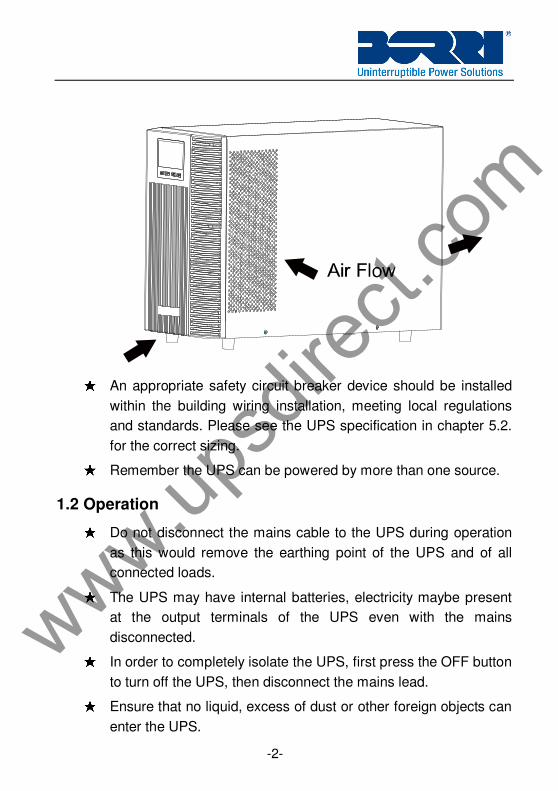
the UPS and the connected load does not exceed 3.5mA. ★ Do not obstruct the ventilation and air flow of the UPS housing.
Ensure the air vents on the front, side and rear of the UPS are not
blocked. Allow at least 25cm of space on each side.
www.upsd
irect.
com
-2-
★ An appropriate safety circuit breaker device should be installed
within the building wiring installation, meeting local regulations
and standards. Please see the UPS specification in chapter 5.2.
for the correct sizing. ★ Remember the UPS can be powered by more than one source.
1.2 Operation ★ Do not disconnect the mains cable to the UPS during operation
as this would remove the earthing point of the UPS and of all
connected loads. ★ The UPS may have internal batteries, electricity maybe present
at the output terminals of the UPS even with the mains
disconnected. ★ In order to completely isolate the UPS, first press the OFF button
to turn off the UPS, then disconnect the mains lead. ★ Ensure that no liquid, excess of dust or other foreign objects can
enter the UPS.
www.upsd
irect.
com
-3-
★ Do not remove the enclosure. This system is to be serviced by
qualified service personnel only.
1.3 Maintenance, servicing and faults ★ Repairs may be carried out only by qualified maintenance
personnel. ★ Caution - risk of electric shock. Even after the unit is
disconnected from the mains power supply (mains input lead),
components inside the UPS are still connected to the battery
which are potentially dangerous. ★ Batteries must be replaced only by qualified personnel. ★ Batteries have a high short-circuit current and pose a risk of
shock. Take all precautionary measures specified below and any
other measures necessary when working with batteries: - remove all jewellery, wristwatches, rings and other metal
objects - use only tools with insulated grips and handles. ★ When changing batteries, replace with the same quantity and the
same type of batteries. ★ Dispose of all batteries according to local standards. ★ Always replace any fuse with one of the same type and rating.
1.4 Transport ★★★★ Please transport the UPS in the original packaging only to protect
against impact damage.
1.5 Storage ★ The UPS must be stored in a dry and well-ventilated area.
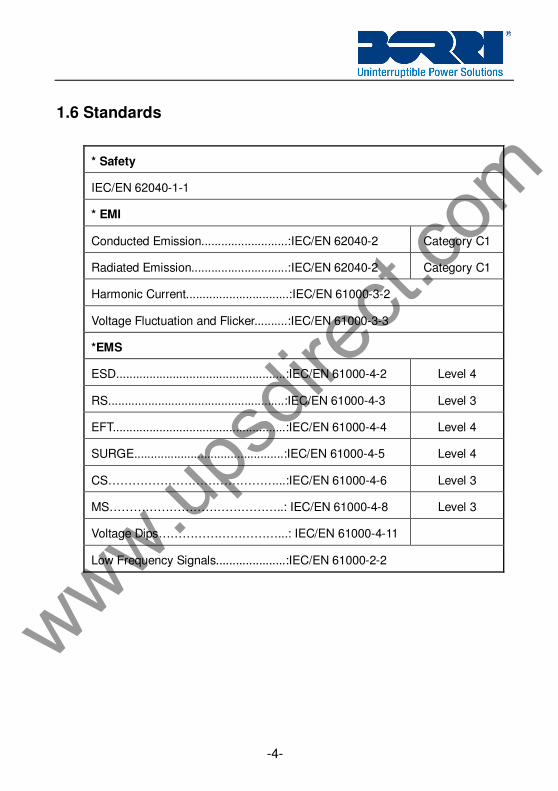
Low Frequency Signals.....................:IEC/EN 61000-2-2
www.upsd
irect.
com
-5-
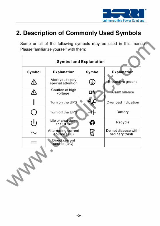
2. Description of Commonly Used Symbols
Some or all of the following symbols may be used in this manual.
Please familiarize yourself with them:
www.upsd
irect.
com
-6-
3. Introduction
This is a Double Conversion true On-Line Uninterruptible Power Supply.
The double-conversion eliminates all mains power disturbances. A
rectifier converts the alternating current (AC) from the mains to direct
current (DC ). This DC charges the batteries and powers the inverter. On
the basis of this DC voltage, the inverter generates a sinusoidal AC
voltage, which permanently supplies the loads.
The connected load is thus powered entirely by the UPS inverter voltage.
In the event of power failure, the maintenance-free batteries power the
inverter.
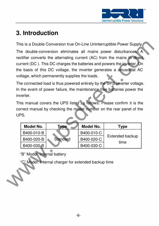
This manual covers the UPS listed as follows. Please confirm it is the
correct manual by checking the model number on the rear panel of the
UPS.
“B” Model: Internal battery
“C” Model: Internal charger for extended backup time
Model No. Type Model No. Type
B400-010-B B400-010-C
B400-020-B B400-020-C
B400-030-B
Standard
B400-030-C
Extended backup
time
www.upsd
irect.
com
-7-
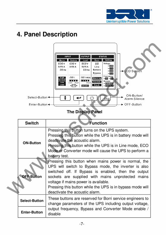
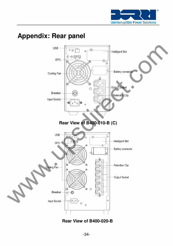
4. Panel Description
The Display Panel
Switch Function
ON-Button
Pressing this button turns on the UPS system.
Pressing this button while the UPS is in battery mode will
deactivate the acoustic alarm.
Pressing this button while the UPS is in Line mode, ECO
Mode or Converter mode will cause the UPS to perform a
battery test.
OFF-Button
Pressing this button when mains power is normal, the
UPS will switch to Bypass mode, the inverter is also
switched off. If Bypass is enabled, then the output
sockets are supplied with mains unprotected mains
voltage if mains power is available.
Pressing this button while the UPS is in bypass mode will
deactivate the acoustic alarm.
Select-Button
Enter-Button
These buttons are reserved for Borri service engineers to
change parameters of the UPS including output voltage,
output frequency, Bypass and Converter Mode enable /
disable
www.upsd
irect.
com
-8-
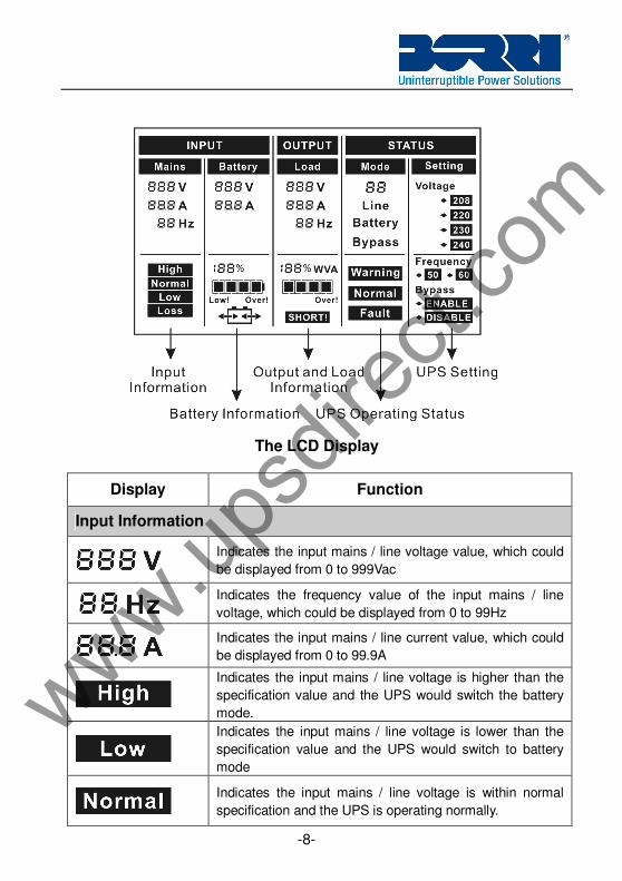
The LCD Display
Display Function
Input Information
Indicates the input mains / line voltage value, which could
be displayed from 0 to 999Vac
Indicates the frequency value of the input mains / line
voltage, which could be displayed from 0 to 99Hz
Indicates the input mains / line current value, which could
be displayed from 0 to 99.9A
Indicates the input mains / line voltage is higher than the
specification value and the UPS would switch the battery
mode.
Indicates the input mains / line voltage is lower than the
specification value and the UPS would switch to battery
mode
Indicates the input mains / line voltage is within normal
specification and the UPS is operating normally.
www.upsd
irect.
com
-9-
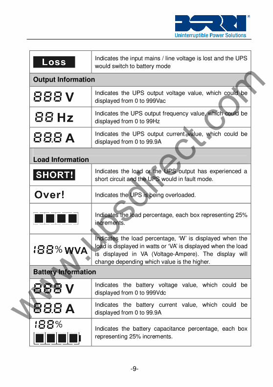
Indicates the input mains / line voltage is lost and the UPS
would switch to battery mode
Output Information
Indicates the UPS output voltage value, which could be
displayed from 0 to 999Vac
Indicates the UPS output frequency value, which could be
displayed from 0 to 99Hz
Indicates the UPS output current value, which could be
displayed from 0 to 99.9A
Load Information
Indicates the load or the UPS output has experienced a
short circuit and the UPS would in fault mode.
Indicates the UPS is being overloaded.
Indicates the load percentage, each box representing 25%
increments.
Indicates the load percentage, ‘W’ is displayed when the
load is displayed in watts or ‘VA’ is displayed when the load
is displayed in VA (Voltage-Ampere). The display will
change depending which value is the higher.
Battery Information
Indicates the battery voltage value, which could be
displayed from 0 to 999Vdc
Indicates the battery current value, which could be
displayed from 0 to 99.9A
Indicates the battery capacitance percentage, each box
representing 25% increments.
www.upsd
irect.
com
-10-
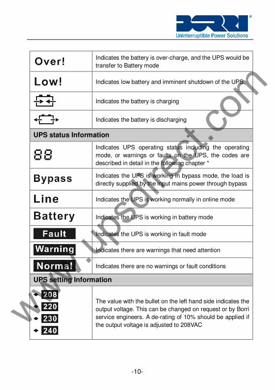
Indicates the battery is over-charge, and the UPS would be
transfer to Battery mode
Indicates low battery and imminent shutdown of the UPS.
Indicates the battery is charging
Indicates the battery is discharging
UPS status Information
Indicates UPS operating status including the operating
mode, or warnings or faults on the UPS, the codes are
described in detail in the following chapter *
Indicates the UPS is working in bypass mode, the load is
directly supplied by the input mains power through bypass
Indicates the UPS is working normally in online mode
Indicates the UPS is working in battery mode
Indicates the UPS is working in fault mode
Indicates there are warnings that need attention
Indicates there are no warnings or fault conditions
UPS setting Information
The value with the bullet on the left hand side indicates the
output voltage. This can be changed on request or by Borri
service engineers. A de-rating of 10% should be applied if
the output voltage is adjusted to 208VAC www.upsd
irect.
com
-11-
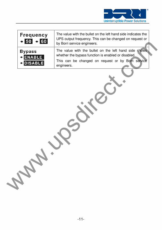
The value with the bullet on the left hand side indicates the
UPS output frequency. This can be changed on request or
by Borri service engineers.
The value with the bullet on the left hand side shows
whether the bypass function is enabled or disabled.
This can be changed on request or by Borri service
engineers.
www.upsd
irect.
com
-12-
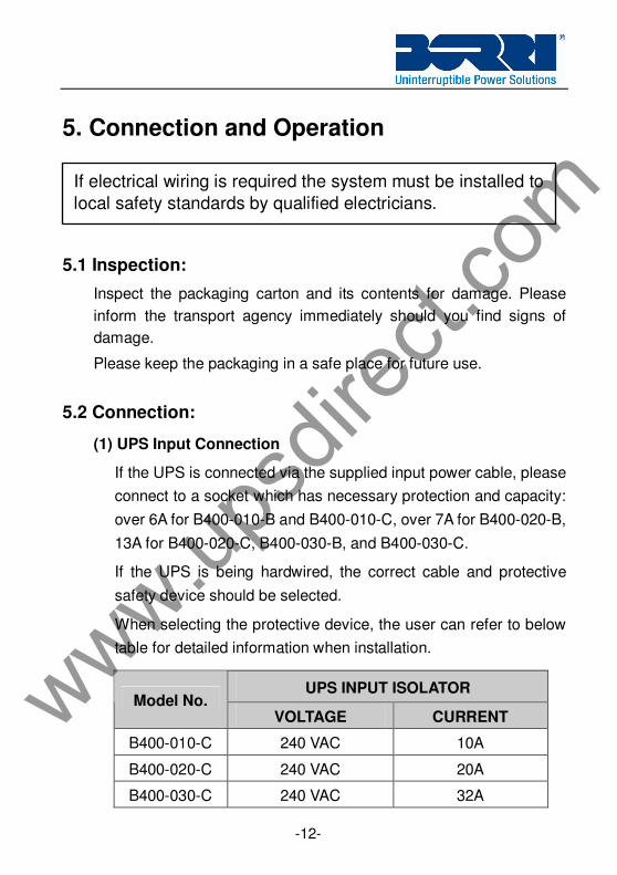
5. Connection and Operation
5.1 Inspection:
Inspect the packaging carton and its contents for damage. Please
inform the transport agency immediately should you find signs of
damage.
Please keep the packaging in a safe place for future use.
5.2 Connection:
(1) UPS Input Connection
If the UPS is connected via the supplied input power cable, please
connect to a socket which has necessary protection and capacity:
over 6A for B400-010-B and B400-010-C, over 7A for B400-020-B,
13A for B400-020-C, B400-030-B, and B400-030-C.
If the UPS is being hardwired, the correct cable and protective
safety device should be selected.
When selecting the protective device, the user can refer to below
table for detailed information when installation.
UPS INPUT ISOLATOR Model No.
VOLTAGE CURRENT
B400-010-C 240 VAC 10A
B400-020-C 240 VAC 20A
B400-030-C 240 VAC 32A
If electrical wiring is required the system must be installed to
local safety standards by qualified electricians.
www.upsd
irect.
com
-13-
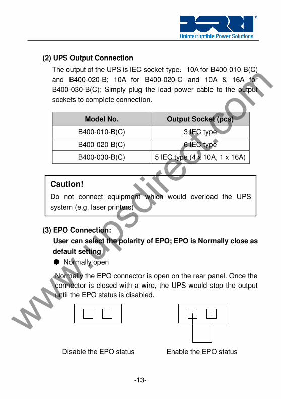
(2) UPS Output Connection
The output of the UPS is IEC socket-type:10A for B400-010-B(C)
and B400-020-B; 10A for B400-020-C and 10A & 16A for
B400-030-B(C); Simply plug the load power cable to the output
sockets to complete connection.
Model No. Output Socket (pcs)
B400-010-B(C) 3 IEC type
B400-020-B(C) 6 IEC type
B400-030-B(C) 5 IEC type (4 x 10A, 1 x 16A)
(3) EPO Connection:
User can select the polarity of EPO; EPO is Normally close as
default setting ● Normally open
Normally the EPO connector is open on the rear panel. Once the
connector is closed with a wire, the UPS would stop the output
until the EPO status is disabled.
Disable the EPO status Enable the EPO status
Caution!
Do not connect equipment which would overload the UPS
system (e.g. laser printers)
www.upsd
irect.
com
-14-
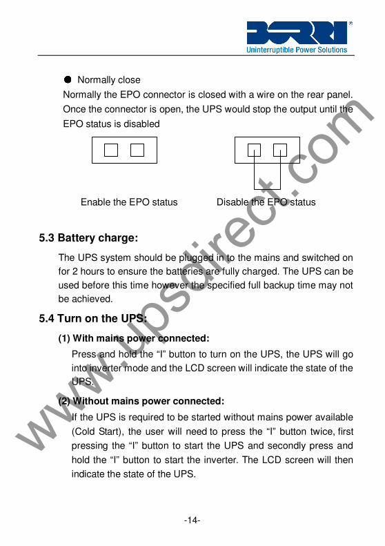
● Normally close
Normally the EPO connector is closed with a wire on the rear panel.
Once the connector is open, the UPS would stop the output until the
EPO status is disabled
Enable the EPO status Disable the EPO status
5.3 Battery charge:
The UPS system should be plugged in to the mains and switched on
for 2 hours to ensure the batteries are fully charged. The UPS can be
used before this time however the specified full backup time may not
be achieved.
5.4 Turn on the UPS:
(1) With mains power connected:
Press and hold the “I” button to turn on the UPS, the UPS will go
into inverter mode and the LCD screen will indicate the state of the
UPS.
(2) Without mains power connected:
If the UPS is required to be started without mains power available
(Cold Start), the user will need to press the “I” button twice, first
pressing the “I” button to start the UPS and secondly press and
hold the “I” button to start the inverter. The LCD screen will then
indicate the state of the UPS.
www.upsd
irect.
com
-15-
5.5 Test function:
The UPS can perform a self-test including checking the battery
status by pressing the On-Switch “I” for more than 1 second.
5.6 Turn off the UPS:
(1) In Inverter Mode:
Press and hold the “ “ button, this will switch the UPS to bypass
mode. If mains voltage is not available the UPS will automatically
shutdown. If mains power is available disconnect the cable.
(2) In Battery Mode:
Press and hold the “ “ button to turn off the UPS, the UPS will then
shutdown.
5.7 Audible alarm mute function:
The audible alarm can be silenced while the UPS is in battery mode
by pressing and holding the “I” button. The alarm will be enabled
when the battery charge is at low level to alert imminent shutdown of
the UPS
The audible alarm can be silenced while the UPS is in bypass mode
by pressing and holding the “ “button. The action doesn’t affect the
warning and fault alarm.
5.8 Operation procedure of external battery for long backup time model (“C” model)
(1) Use the battery pack with voltage: 36VDC for B400-010-C (3 pcs
of 12V batteries), 96VDC for B400-020-C / B400-030-C (8 pcs of
12V batteries). Connection of batteries with a different string
voltage will cause permanent damage to the batteries and UPS.
www.upsd
irect.
com
-16-
(2) The battery connection procedure is very important. It must be
followed exactly to avoid electric shock.
(3) Make sure the mains input is off, if there is a battery breaker then
turn it off first.
(4) Remove the cover of the battery connector on the rear of the UPS,
always use the Borri provided battery connection cable.
(5) Pay attention to the colour of UPS battery connector: red is the
“+” terminal of the battery and black is the “-” terminal of battery,
the green one is the earth. Because the connector is ANDERSON
type, the wires, which is used to the connector, should be the
same type. (Note: the green/yellow wire is grounded for
protection purpose)
(6) Connect the cable to the UPS and battery box.
(7) Turn on the UPS, the batteries will then start to be charged.
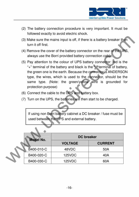
DC breaker
Model No. VOLTAGE CURRENT
B400-010-C 48VDC 50A
B400-020-C 125VDC 40A
B400-030-C 125VDC 60A
If using non Borri battery cabinet a DC breaker / fuse must be
used between the UPS and external battery.
www.upsd
irect.
com
-17-
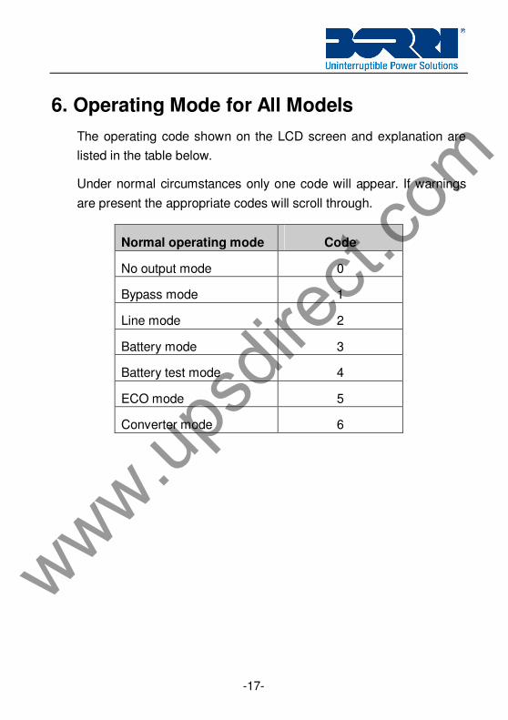
6. Operating Mode for All Models
The operating code shown on the LCD screen and explanation are
listed in the table below.
Under normal circumstances only one code will appear. If warnings
are present the appropriate codes will scroll through.
Normal operating mode Code
No output mode 0
Bypass mode 1
Line mode 2
Battery mode 3
Battery test mode 4
ECO mode 5
Converter mode 6
www.upsd
irect.
com
-18-
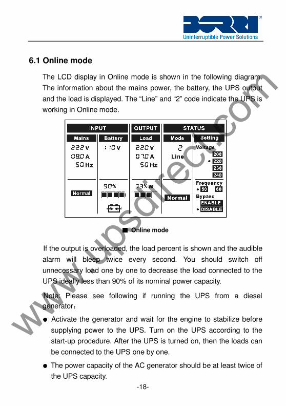
6.1 Online mode
The LCD display in Online mode is shown in the following diagram.
The information about the mains power, the battery, the UPS output
and the load is displayed. The “Line” and “2” code indicate the UPS is
working in Online mode.
If the output is overloaded, the load percent is shown and the audible
alarm will bleep twice every second. You should switch off
unnecessary load one by one to decrease the load connected to the
UPS ideally less than 90% of its nominal power capacity.
Note: Please see following if running the UPS from a diesel
generator: ● Activate the generator and wait for the engine to stabilize before
supplying power to the UPS. Turn on the UPS according to the
start-up procedure. After the UPS is turned on, then the loads can
be connected to the UPS one by one. ● The power capacity of the AC generator should be at least twice of
the UPS capacity.
■■■■ Online mode
www.upsd
irect.
com
-19-
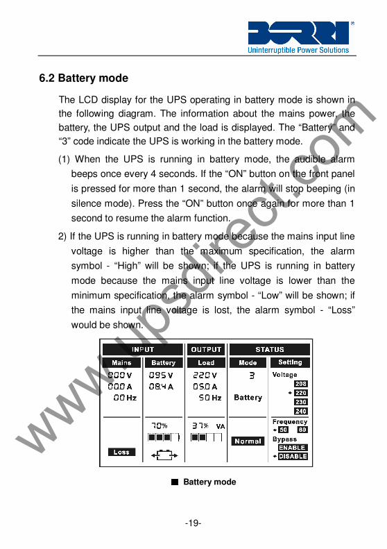
6.2 Battery mode
The LCD display for the UPS operating in battery mode is shown in
the following diagram. The information about the mains power, the
battery, the UPS output and the load is displayed. The “Battery” and
“3” code indicate the UPS is working in the battery mode.
(1) When the UPS is running in battery mode, the audible alarm
beeps once every 4 seconds. If the “ON” button on the front panel
is pressed for more than 1 second, the alarm will stop beeping (in
silence mode). Press the “ON” button once again for more than 1
second to resume the alarm function.
2) If the UPS is running in battery mode because the mains input line
voltage is higher than the maximum specification, the alarm
symbol - “High” will be shown; if the UPS is running in battery
mode because the mains input line voltage is lower than the
minimum specification, the alarm symbol - “Low” will be shown; if
the mains input line voltage is lost, the alarm symbol - “Loss”
would be shown.
■■■■ Battery mode
www.upsd
irect.
com
-20-
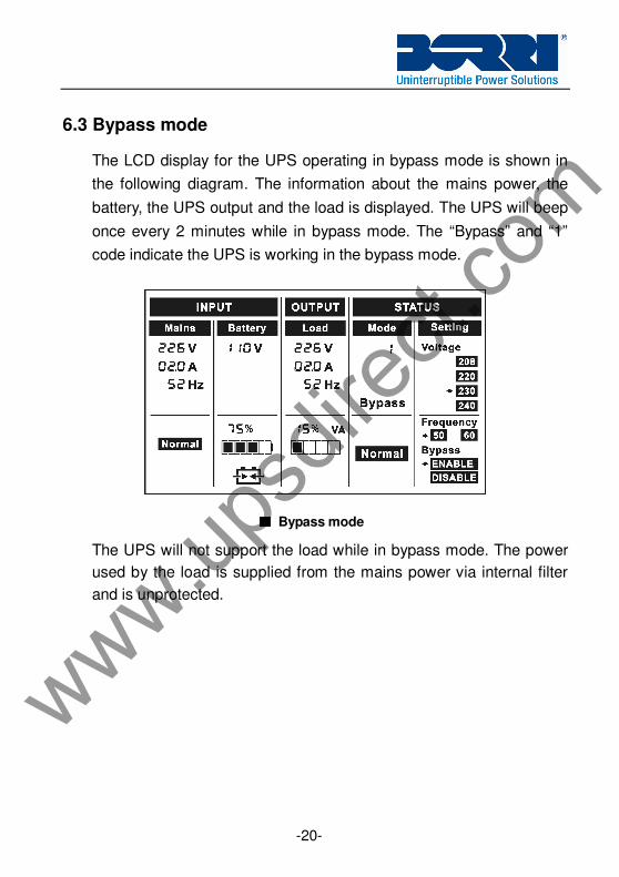
6.3 Bypass mode
The LCD display for the UPS operating in bypass mode is shown in
the following diagram. The information about the mains power, the
battery, the UPS output and the load is displayed. The UPS will beep
once every 2 minutes while in bypass mode. The “Bypass” and “1”
code indicate the UPS is working in the bypass mode.
The UPS will not support the load while in bypass mode. The power
used by the load is supplied from the mains power via internal filter
and is unprotected.
■■■■ Bypass mode
www.upsd
irect.
com
-21-
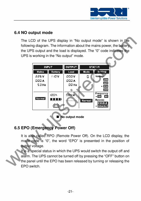
6.4 NO output mode
The LCD of the UPS display in “No output mode” is shown in the
following diagram. The information about the mains power, the battery,
the UPS output and the load is displayed. The “0” code indicates the
UPS is working in the “No output” mode.
6.5 EPO (Emergency Power Off)
It is also called RPO (Remote Power Off). On the LCD display, the
mode code is “0”, the word “EPO” is presented in the position of
output voltage.
It is a special status in which the UPS would switch the output off and
alarm. The UPS cannot be turned off by pressing the “OFF” button on
the panel until the EPO has been released by turning or releasing the
EPO switch.
■■■■ No output mode
www.upsd
irect.
com
-22-
6.6 ECO mode (High Efficiency Mode)
In ECO mode the UPS LCD will display the mode code “5”.
After the UPS is turned on, the power used by the load is supplied
from the mains power via the internal filter while the mains power is in
normal range. Once the mains power is lost or abnormal, the UPS will
transfer to battery mode and the load is supplied continuously by the
battery.
1) This mode can be enabled through the LCD setting or software.
2) The transfer time of UPS output from ECO mode to battery mode is
less than 10ms.
6.7 Converter mode
In converter mode the UPS LCD will display the mode code “6”.
The UPS would run with a fixed output frequency (50Hz or 60Hz) in
converter mode. Once the mains power is lost or abnormal, the UPS
would transfer to battery mode and the load is supplied continuously
by the battery.
1) This mode can be enabled through the LCD setting or software.
2) The load should be derating to 60% in converter mode.
6.8 Abnormal mode
In abnormal mode such as Bus fault etc., the corresponding fault code
would be shown to indicate the operating mode of the UPS. Some
other warnings could also be shown, for example “short!” would be
shown when the load or the UPS output is subject to a short circuit
and the UPS is in inverter fault mode.
www.upsd
irect.
com
-23-
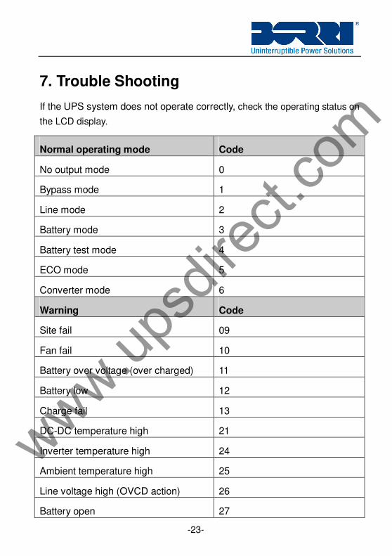
7. Trouble Shooting
If the UPS system does not operate correctly, check the operating status on
the LCD display.
Normal operating mode Code
No output mode 0
Bypass mode 1
Line mode 2
Battery mode 3
Battery test mode 4
ECO mode 5
Converter mode 6
Warning Code
Site fail 09
Fan fail 10
Battery over voltage (over charged) 11
Battery low 12
Charge fail 13
DC-DC temperature high 21
Inverter temperature high 24
Ambient temperature high 25
Line voltage high (OVCD action) 26
Battery open 27
www.upsd
irect.
com
-24-
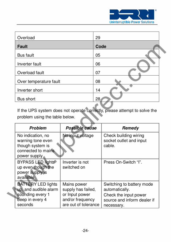
Overload 29
Fault Code
Bus fault 05
Inverter fault 06
Overload fault 07
Over temperature fault 08
Inverter short 14
Bus short 28
If the UPS system does not operate correctly, please attempt to solve the
problem using the table below.
Problem Possible cause Remedy
No indication, no warning tone even though system is connected to mains power supply
No input voltage Check building wiring socket outlet and input cable.
BYPASS LED lights up even though the power supply is available
Inverter is not switched on
Press On-Switch “I”.
BATTERY LED lights
up, and audible alarm sounding every 1 beep in every 4 seconds
Mains power
supply has failed, or Input power and/or frequency are out of tolerance
Switching to battery mode
automatically.
Check the input power source and inform dealer if necessary.
www.upsd
irect.
com
-25-
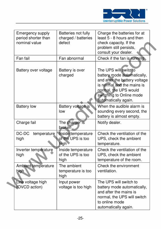
Emergency supply period shorter than nominal value
Batteries not fully charged / batteries defect
Charge the batteries for at least 5 - 8 hours and then check capacity. If the problem still persists, consult your dealer.
Fan fail Fan abnormal Check if the fan is running
Battery over voltage
Battery is over
charged
The UPS will switc to
battery mode automatically,
and after the battery voltage
is normal and the mains is
normal, the UPS would
switching to Online mode
automatically again.
Battery low Battery voltage is
low
When the audible alarm is
sounding every second, the
battery is almost empty.
Charge fail The charger is
broken
Notify dealer.
DC-DC temperature
high
Inside temperature
of the UPS is too
high
Check the ventilation of the
UPS, check the ambient
temperature.
Inverter temperature
high
Inside temperature
of the UPS is too
high
Check the ventilation of the
UPS, check the ambient
temperature of the room.
Ambient temperature
high
The ambient
temperature is too
high
Check the environment
ventilation.
Line voltage high
(OVCD action)
Input power
voltage is too high
The UPS will switch to
battery mode automatically,
and after the mains is
normal, the UPS will switch
to online mode
automatically again.
www.upsd
irect.
com
-26-
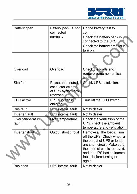
Battery open Battery pack is not
connected
correctly
Do the battery test to
confirm.
Check the battery bank is
connected to the UPS.
Check the battery breaker is
turn on.
Overload
Overload
Check the loads and
remove some non-critical
loads.
Site fail Phase and neutral conductor at input of UPS system are reversed
Check UPS installation.
EPO active EPO function is enabled
Turn off the EPO switch.
Bus fault UPS internal fault Notify dealer
Inverter fault UPS internal fault Notify dealer
Over temperature fault
Over temperature Check the ventilation of the UPS, check the ambient temperature and ventilation.
Inverter short Output short circuit Remove all the loads. Turn
off the UPS. Check whether the output of UPS or loads are short circuit. Make sure the short circuit is removed, and the UPS has no internal faults before turning on again.
Bus short UPS internal fault Notify dealer
www.upsd
irect.
com
-27-
Please have the following information available before calling the
After-Sales Service Department:
1. Model number, serial number
2. Date on which the problem occurred
3. LCD/LED display status, Buzzer alarm status
4. Utility power condition, load type and capacity, environment
temperature, ventilation condition
5. The information (battery capacity, quantity) of external battery pack
if the UPS is “C” model
6. Other information for complete description of the problem
www.upsd
irect.
com
-28-
8. Maintenance
8.1 Operation
The UPS system contains no user-serviceable parts. If the battery
service life (3~5 years at 25°C ambient temperature) has been
exceeded, the batteries must be replaced. In this case please contact
Borri.
8.2 Storage
If the batteries are stored in a temperate controlled area, they should
be charged every three months for 1~2 hours. You should shorten the
charging intervals to two months at locations subject to high
temperatures.
8.3 Battery Replacement
If the battery service life has been exceeded, the batteries must be
replaced.
Battery replacement should be performed only by qualified personnel.
www.upsd
irect.
com
-29-
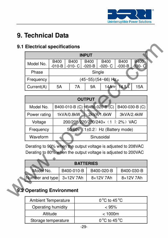
9. Technical Data
9.1 Electrical specifications
INPUT
Model No. B400
-010-B B400
-010- C B400
-020-B B400
-020- C B400
-030-B B400
-030- C
Phase Single
Frequency (45~55)/(54~66) Hz
Current(A) 5A 7A 9A 14A 14.5A 15A
OUTPUT
Model No. B400-010-B (C) B400-020-B (C) B400-030-B (C)
Power rating 1kVA/0.8kW 2kVA/1.6kW 3kVA/2.4kW
Voltage 200/208/220/230/240×(1 士 2%)VAC
Frequency 50/60×(1±0.2)Hz (Battery mode)
Waveform Sinusoidal
Derating to 90% when the output voltage is adjusted to 208VAC
Derating to 80% when the output voltage is adjusted to 200VAC
BATTERIES
Model No. B400-010-B B400-020-B B400-030-B
Number and type 3×12V 7Ah 8×12V 7Ah 8×12V 7Ah
9.2 Operating Environment
Ambient Temperature 0 oC to 45 oC
Operating humidity < 95%
Altitude < 1000m
Storage temperature 0 oC to 45 oC
www.upsd
irect.
com
-30-
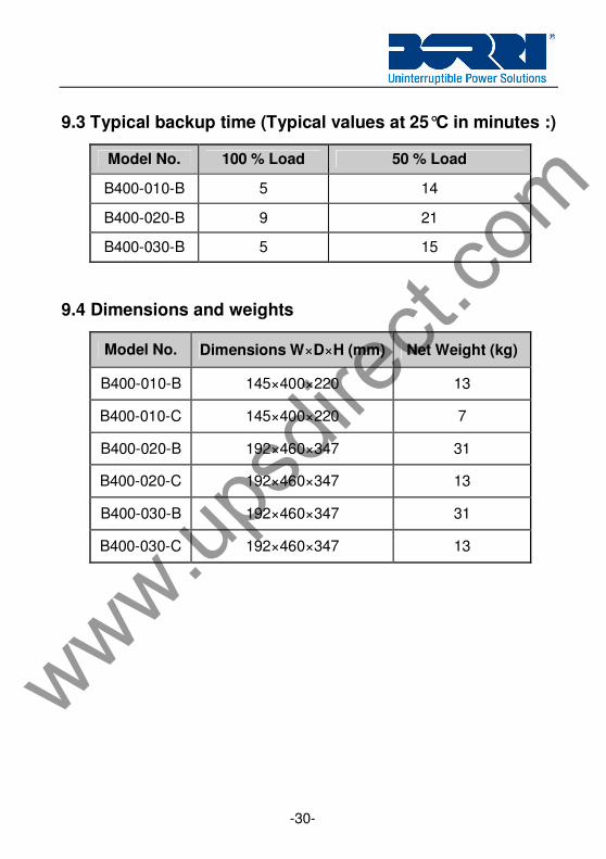
9.3 Typical backup time (Typical values at 25°C in minutes :)
Model No. 100 % Load 50 % Load
B400-010-B 5 14
B400-020-B 9 21
B400-030-B 5 15
9.4 Dimensions and weights
Model No. Dimensions W×D×H (mm) Net Weight (kg)
B400-010-B 145×400×220 13
B400-010-C 145×400×220 7
B400-020-B 192×460×347 31
B400-020-C 192×460×347 13
B400-030-B 192×460×347 31
B400-030-C 192×460×347 13
www.upsd
irect.
com
-31-
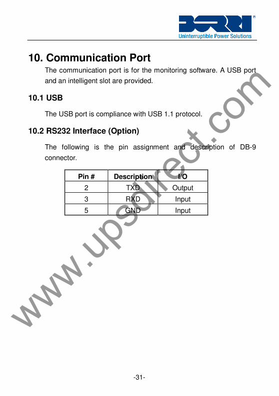
10. Communication Port The communication port is for the monitoring software. A USB port
and an intelligent slot are provided.
10.1 USB
The USB port is compliance with USB 1.1 protocol.
10.2 RS232 Interface (Option)
The following is the pin assignment and description of DB-9
connector.
Pin # Description I/O
2 TXD Output
3 RXD Input
5 GND Input
www.upsd
irect.
com
-32-
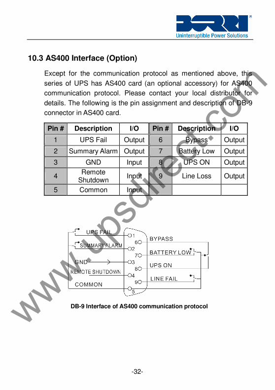
10.3 AS400 Interface (Option)
Except for the communication protocol as mentioned above, this
series of UPS has AS400 card (an optional accessory) for AS400
communication protocol. Please contact your local distributor for
details. The following is the pin assignment and description of DB-9
connector in AS400 card.
Pin # Description I/O Pin # Description I/O
1 UPS Fail Output 6 Bypass Output
2 Summary Alarm Output 7 Battery Low Output
3 GND Input 8 UPS ON Output
4 Remote
Shutdown Input 9 Line Loss Output
5 Common Input
DB-9 Interface of AS400 communication protocol
www.upsd
irect.
com
-33-
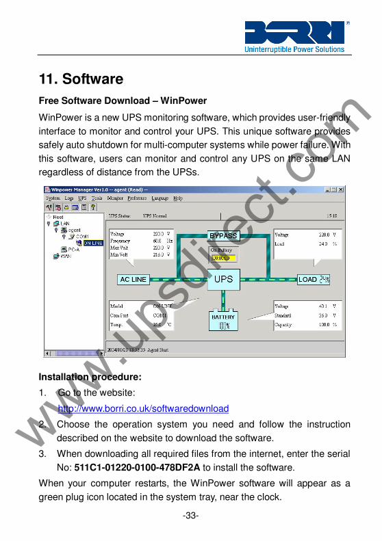
11. Software
Free Software Download – WinPower
WinPower is a new UPS monitoring software, which provides user-friendly
interface to monitor and control your UPS. This unique software provides
safely auto shutdown for multi-computer systems while power failure. With
this software, users can monitor and control any UPS on the same LAN
regardless of distance from the UPSs.
Installation procedure:
1. Go to the website:
http://www.borri.co.uk/softwaredownload
2. Choose the operation system you need and follow the instruction
described on the website to download the software.
3. When downloading all required files from the internet, enter the serial
No: 511C1-01220-0100-478DF2A to install the software.
When your computer restarts, the WinPower software will appear as a
green plug icon located in the system tray, near the clock.