78
TheoDist FTD 05 Reflectorless Construction Tachymeter USER MANUAL
| Date post: | 29-Dec-2015 |
| Category: |
Documents |
| Upload: | cristian-felipe-castillo-villalobos |
| View: | 135 times |
| Download: | 19 times |

TheoDist FTD 05
Reflectorless Construction Tachymeter
USER MANUAL

TheoDist FTD 05 User Manual
Page 2 of 78
Contents: 1 Preface ................................................................................................................................ 4 2 PRECAUTIONS FOR SAFE OPERATION ..................................................................... 5
2.1 General ....................................................................................................................... 5 2.2 Power supply .............................................................................................................. 5 2.3 Tripod ......................................................................................................................... 5 2.4 Laser Safety Information ............................................................................................ 5
3 PRECAUTIONS ................................................................................................................ 6 3.1 Precautions Concerning Water and Dust Resistance ................................................. 6 3.2 Using .......................................................................................................................... 6 3.3 Other Precautions ....................................................................................................... 6
4 Nomenclature and function ................................................................................................ 7 4.1 Parts of the instrument ................................................................................................ 7 4.2 Take out the instrument from the case and put it back. .............................................. 8 4.3 Using the battery ........................................................................................................ 8
5 Basic key operation and display ....................................................................................... 10 5.1 Screen and keyboard ................................................................................................ 10 5.2 Operation key ........................................................................................................... 10 5.3 Method of inputting numerals and alphabets ........................................................... 11
6 Preparation for measurement ........................................................................................... 12 6.1 Setting up the instrument and the tripod .................................................................. 12 6.2 Levelling and Centring the instrument ..................................................................... 12 6.3 Focusing and target sighting .................................................................................... 13 6.4 Power ON/OFF ........................................................................................................ 14 6.5 Tilt angle display and compensation ........................................................................ 14
7 Basic measurement ........................................................................................................... 15 7.1 Angle measurement .................................................................................................. 15 7.2 Distance measurement .............................................................................................. 19 7.3 Coordinate measurement .......................................................................................... 25
8 Setting-out measurement .................................................................................................. 31 8.1 Distance & Angle setting-out ................................................................................... 31 8.2 Coordinate setting-out .............................................................................................. 34
9 Data Recording ................................................................................................................. 36 9.1 Select a JOB for recording data ................................................................................ 36 9.2 Set instrument station and record the station data .................................................... 37 9.3 Set back sight direction angle and record the direction angle data .......................... 38 9.4 Record measurement data ........................................................................................ 39 9.5 Configuration of data recording ............................................................................... 40 9.6 Reviewing the data in the current JOB ..................................................................... 40 9.7 Measure and record data in basic measurement mode by pressing one key ............ 41
10 Memory management ................................................................................................... 42 10.1 JOB manager ............................................................................................................ 42 10.2 Management of Known Coord ................................................................................. 46

TheoDist FTD 05 User Manual
Page 3 of 78
10.3 Code manager ........................................................................................................... 48 10.4 Display status of memory ......................................................................................... 49 10.5 Format memory ........................................................................................................ 49
11 Data communication .................................................................................................... 50 11.1 Settings of communication ....................................................................................... 50 11.2 Send JOB data .......................................................................................................... 51 11.3 Receive known point coordinate data ...................................................................... 52
12 Application Program .................................................................................................... 53 12.1 Resection measurement ............................................................................................ 53 12.2 Offset measurement .................................................................................................. 56 12.3 Missing line measurement ........................................................................................ 60 12.4 Remote elevation measurement ............................................................................... 63 12.5 Area calculation ........................................................................................................ 66
13 Setting parameters of instrument .................................................................................. 68 13.1 Items set and options ................................................................................................ 69 13.2 Operation of setting parameters ............................................................................... 71 13.3 Define function of the USER key ............................................................................ 71
14 Checks and adjustments ............................................................................................... 72 14.1 Checking and adjusting Plate level and circular level .............................................. 72
15 Maintenance ................................................................................................................. 73 16 Error message ............................................................................................................... 74 17 Specifications ............................................................................................................... 75
17.1 Pin Assignments ....................................................................................................... 76 18 About us ....................................................................................................................... 77 19 Index ............................................................................................................................. 78
TheoDist FTD 05 User Manual
Page 4 of 78
1 Preface Thank you for selecting the TheoDist FTD 05 Reflectorless Construction Tachymeter. For the best performance of the instrument, please read this manual carefully and keep it in a convenient location for future reference. Some of the diagrams shown in this manual may be simplified for easier reading. No further notice will be given for any changes of technical specifications or appearance to the apparatus for the improvement of performance and preciseness.

TheoDist FTD 05 User Manual
Page 5 of 78
2 PRECAUTIONS FOR SAFE OPERATION 2.1 General
o Do not use the unit in areas exposed to high amounts of dust or ash, in areas where there is inadequate ventilation, or near combustible materials. An explosion could occur.
o Do not perform disassembly or rebuilding. Fire, electric shock or burns could result. o Never look at the sun through the telescope. Loss of eyesight could result. o Use solar filter for sun observation. o Do not use the carrying case as a footstool. The case is slippery and unstable so a person
could slip and fall off it. o Do not wield or throw the plumb bob. A person could be injured if struck. o Secure handle to main unit with locking screws. Failure to properly secure the handle could
result in the unit falling off while being carried, causing injury. o Tighten the adjustment tribrach clamp securely. Failure to properly secure the clamp could
result in the tribrach falling off while being carried, causing injury.
2.2 Power supply o Do not use voltage other than the specified power supply voltage. Fire or electrical shock
could result. o Do not use damaged power cords, plugs or loose outlets. Fire or electric shock could result. o Do not use power cords other than those designated. Fire could result. o Do not place articles such as clothing on the battery charger while charging batteries. Sparks
could be induced, leading to fire. o Use only the specified battery charger to recharge batteries. o Do not heat or throw batteries into fire. An explosion could occur, resulting in injury. o To prevent shorting of the battery in storage, apply insulating tape or equivalent to the
terminals. Otherwise shorting could occur resulting in fire or burns. o Do not use batteries or the battery charger if wet. Resultant shorting could lead to fire or
burns. o Do not use connect or disconnect power supply plugs with wet hands. Electric shock could
result. o Do not touch liquid leaking from batteries. Harmful chemicals could cause burns or blisters.
2.3 Tripod o When mounting the instrument to the tripod, tighten the centering screw securely. Failure to
tighten the screw properly could result in the instrument falling off the tripod, causing injury. o Tighten securely the leg fixing screws of the tripod on which the instrument is mounted.
Failure to tighten the screws could result in the tripod collapsing, causing injury. o Keep hands and feet away from the tripod shoes when fixing the tripod in the ground. A hand
or foot stab wound could result. o Tighten the leg fixing screws securely before carrying the tripod. Failure to tighten the screws
could lead to the tripod legs extending, causing injury.
2.4 Laser Safety Information The TheoDist FTD 05 is equipped with Class 3R laser source for distance measuring, and with laser plummet, do not look directly into the laser beam. Doing so could cause eye damage. Do not frequently start and shut down the laser plummet, which may cause damage to it.

TheoDist FTD 05 User Manual
Page 6 of 78
3 PRECAUTIONS 3.1 Precautions Concerning Water and Dust Resistance
o Do not put the instrument in the water. The instrument conforms to IPX4, so the normal rain can not damage to the instrument.
o Be sure to close the battery cover and correctly attach the connector caps to protect the instrument from moisture and dust particles.
o Make sure that the inside of the carrying case and the instrument is dry before closing the case. If moisture is trapped inside the case, it may cause the instrument to rust.
o Never place the instrument directly on the ground. Sand or dust may cause damage to the screw holes or the centring screw on the base plate.
3.2 Using o Mount the instrument on the wooden tripod, because the metal tripod will shake, and it will
decrease the observing precision. o The tribrach will affect the precision of the instrument; you should check the screw on it. It
must be tighten in order to protect the instrument. o Before your measurement, check all the settings and the parameter of the instrument
carefully. o Never carry the instrument on the tripod to another site. o Turn the power off before removing the battery.
3.3 Other Precautions o If the instrument is moved from a warm place to an extremely cold place, internal parts may
contract and make the keys difficult to operate. This is caused by cold air trapped inside the hermetically sealed casing. If the keys do not depress, open the battery cover to resume normal functionality. To prevent the keys from becoming stiff, remove the connector caps before moving the instrument to a cold place.
o Protect the instrument from heavy shocks or vibration.

TheoDist FTD 05 User Manual
Page 7 of 78
4 Nomenclature and function 4.1 Parts of the instrument
TheoDist FTD 05 User Manual
Page 8 of 78
4.2 Take out the instrument from the case and put it back. Take out the instrument from the carrying case
o Lays down the instrument carrying case with lid up. o Unlock the case and open it. o Take out the instrument from the case with care.
Put instrument back to the case
o Cover lens of the telescope with the lid. o Make the instrument horizontal with vertical brake hand wheel and circular bubble face up.
And objective lens faces down. Put the instrument back to the case. o Close the case and lock it.
4.3 Using the battery
4.3.1 Cautions: o When the instrument is working on, don’t remove the battery. o Before removing the battery, turn off the power to the instrument. o When installing/removing the battery, make sure that moisture or dust particles do not come in
contact with the inside of the instrument. o Periodically wipe clean the pole with the cleaning cloth to keep them free of dirt. o Please charge the battery at this temperature range 0°~45°. o Before storing the battery, you should charge it full, and you should charge it every three
months at least. If not doing so, the battery will discharge by itself, and the voltage will be very low. Life of the battery will be affected.
o The temperature and the humidity will affect the battery discharge speed. So we advice you store the battery in a dry room and the temperature range should be 0°~20°.
4.3.2 Charging procedure (1) Connect the charger connector to the battery. Make sure the battery contact the charger well. (2) Plug the charger into the wall outlet. Then charging will start, the red lamp will blink. (3) When charging finished, the lamp light turns to green. Unplug the charger and then remove
the battery from the charger.
4.3.3 Charger operation manual o Never use this charger with other batteries. o This charger is a speedy set. It will finish the speed-charging in four hours. o After speed-charging, the capability of the battery will attain 75%~80%. If you want to charge it
full, you need 2~4 hours small current charging. o When the charger is empty or in the small current charging, the green light will bright. In the
speediness status the red light will bright, when it finished, it will turn into the small current status.
o The battery will not be damaged in the small current status, but you had better charge the battery not over twenty-four hours.
o If there is much electricity remains in the batteries, the charger may not come in the speediness status. It will charge it in the small current status. If you want to charge it speediness, you must put the batteries in the charger and then connect the charger with the power supply.
TheoDist FTD 05 User Manual
Page 9 of 78
4.3.4 Mounting the battery Insert the battery by aligning the battery guide with the guide hole in the instrument. While pressing the release button of the battery downward, push the battery toward the instrument until a click is heard.
4.3.5 Removing the battery While pressing the release button of the battery downward, remove the battery by pulling it toward you.
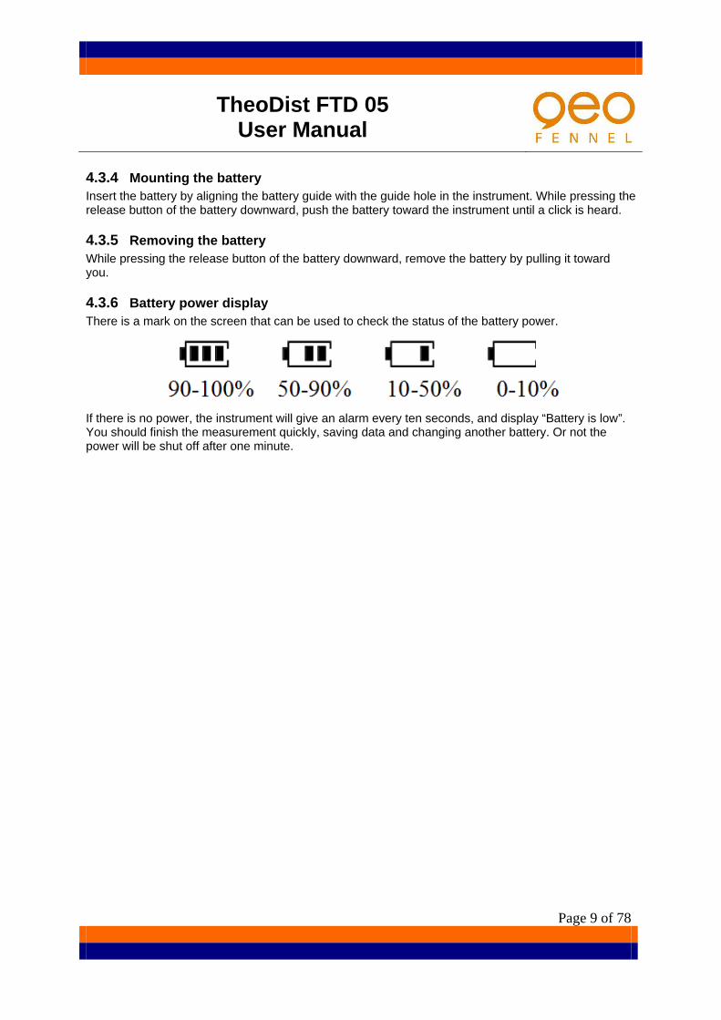
4.3.6 Battery power display There is a mark on the screen that can be used to check the status of the battery power.
If there is no power, the instrument will give an alarm every ten seconds, and display “Battery is low”. You should finish the measurement quickly, saving data and changing another battery. Or not the power will be shut off after one minute.

TheoDist FTD 05 User Manual
Page 10 of 78
5 Basic key operation and display 5.1 Screen and keyboard
5.2 Operation key Key Function
Press this key to turn power on, press and hold it to turn power off.
ESC Cancel the input data or return to the previous screen. LCD lighting switch.( press and hold it to turn on laser plummet)
F1~F5 Select the function matching the soft keys. ANG Enter the angle measurement mode.(cursor move to left) DIST Enter the distance measurement mode(cursor move to right)
COORD Enter the coordinate measurement mode(cursor move to up) S-O Enter the setting-out measurement (cursor move to down)
USER Enter the user-defined function from basic measurement mode MENU Enter the main menu from basic measurement mode
Numeric/Alpha key Input the numerals or alphabets.
TheoDist FTD 05 User Manual
Page 11 of 78
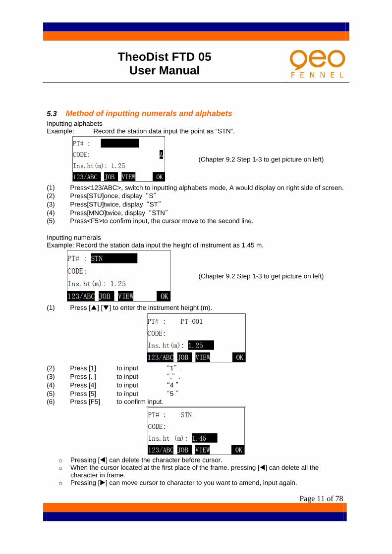
5.3 Method of inputting numerals and alphabets Inputting alphabets Example: Record the station data input the point as “STN”.
(Chapter 9.2 Step 1-3 to get picture on left)
(1) Press<123/ABC>, switch to inputting alphabets mode, A would display on right side of screen. (2) Press[STU]once, display“S” (3) Press[STU]twice, display“ST” (4) Press[MNO]twice, display“STN” (5) Press<F5>to confirm input, the cursor move to the second line. Inputting numerals Example: Record the station data input the height of instrument as 1.45 m.
(Chapter 9.2 Step 1-3 to get picture on left)
(1) Press [▲] [▼] to enter the instrument height (m).
(2) Press [1] to input “1”. (3) Press [. ] to input “.”. (4) Press [4] to input “4 ” (5) Press [5] to input “5 ” (6) Press [F5] to confirm input.
o Pressing [] can delete the character before cursor. o When the cursor located at the first place of the frame, pressing [] can delete all the
character in frame. o Pressing [] can move cursor to character to you want to amend, input again.

TheoDist FTD 05 User Manual
Page 12 of 78
6 Preparation for measurement 6.1 Setting up the instrument and the tripod (1) Adjust the tripod legs so that a height suitable for observation is obtained, make sure the legs
are spaced at equal intervals and the tripod head is as level as possible. Set the tripod so that the head is positioned over the surveying point. Make sure the tripod shoes are firmly fixed in the ground.
(2) Place the instrument on the tripod carefully, loosen the centre screw little, and move the
instrument lightly, until the hammer ball coincides with the station point, then tighten the centre screw to make sure it is secured to the tripod.
6.2 Levelling and Centring the instrument
6.2.1 Levelling the instrument with the circular level (1) Rotate the foot screw’s A, B; make the bubble to the vertical line of the foot screw centre line. (2) Rotate the foot screw C; make the bubble in the centre.

TheoDist FTD 05 User Manual
Page 13 of 78
6.2.2 Levelling the instrument with the plate level (1) Loosen the horizontal clamp to turn the upper part of the
instrument until the plate level is parallel to a line between levelling foot screws A and B. Centre the air bubble using levelling foot screws A and B. the bubble moves towards a clockwise rotated levelling foot screw.
(2) Turn the upper part of the instrument though 90° (100g). The plate level is now perpendicular to a line between levelling foot screws A and B. centre the air bubble using levelling foot screw C.
6.2.3 Centring the instrument with optical/laser plummet Adjust the eyepiece of the optical plummet telescope to the user’s eyesight. Move the instrument by loosening adjusting screw. Coincide image of the point on the ground with the centre mark of the optical plummet telescope. Carefully move the instrument in order to make it steady. Caution: don’t rotate the instrument on the tripod, in
order to decrease the excursion of the bubble.
6.2.4 Levelling the instrument accurately Follow the step 6.2.1~6.2.3, until you rotate the instrument and the bubble always in centre. Tighten the centre screw.
6.3 Focusing and target sighting o Focus on the reticle: look through the telescope eyepiece at a bright and featureless
background. Turn the eyepiece screw clockwise, then counter clockwise little by little until just before the reticle image becomes focused. Using these procedures, frequent reticle refocusing is not necessary since your eye is focused at infinity.
o Sight the target: loosen the vertical and horizontal clamps, and then use the peep sight to bring the target into the field of view. Tighten both clamps.
o Focus on the target: turn the telescope focusing ring to focus on the target. Turn the vertical and horizontal fine motion screws to align the target with the reticle. The last adjustment of each fine motion screw should be in the clockwise direction.
o Readjust the focus until there is no parallax: readjust the focus with the focusing ring until there is no parallax between the target image and the reticle.
Caution: When sighting the target, strong light shining directly into the objective lens
may cause the instrument to malfunction. Protect the objective lens from direct light by attaching the lens hood.

TheoDist FTD 05 User Manual
Page 14 of 78
6.4 Power ON/OFF o Confirm that the instrument is levelled and centred precisely. o Press the power key, instrument is powered on. The instrument will make a sound of beep, a
self-check is run ,while the screen display the instrument model information, instrument number and the software version number. If the instrument is normal, screen display "Turn telescope" prompt.
o Rotate telescope, the instrument will make a sound of beep, and vertical angle index setting finished, enter basic measurement mode.
Caution:
When the battery capacity is insufficient to support the instrument normal working, press the power key, the screen will display “battery is low”, and the instrument will turn power off automatically.
After power on, you should pay attention to the mark indicates the battery power remaining on screen. Confirm that the battery power is enough for work; otherwise you should replace the battery or charge the battery.
If “over range” is displayed, the instrument tilt sensor is indicating that the instrument is out of level, need to be levelled once again.
Due to vibration or strong wind, the angle display is unsteady. You should turn off the tilt angle compensation before measurement. Please see below for details.
6.5 Tilt angle display and compensation The TheoDist FTD 05 has a tilt compensator,it can compensate the error that cause by tilt of vertical axis. The following explains how to check the tilt angle value and turn on/off compensation function.
(1) Enter basic measurement mode after power on.
(2) Press [ANG] to enter angle measurement mode, press [>>] to enter the second page; press [TILT] to display tilt angle of vertical axis.
(3) Press [ON] or [OFF] to turn on or off the function of compensation. Press [ESC] to exit after setting.
To set automatic tilt compensation after power on, please see "13.Setting parameters of instrument".

TheoDist FTD 05 User Manual
Page 15 of 78
7 Basic measurement Basic measurement includes angle measurement, distance measurement, coordinate measurement.
7.1 Angle measurement Before the measurement, please inspect once more and make sure the instrument is levelled
and centred precisely.
After power on, press [ANG] key on the panel to enter the angle measurement mode, carrying on the function related to measurement of angle. The function allocated at two pages, can be switched by pressing [> > ].
7.1.1 Measuring the horizontal angle between two points Use the “0 SET” function to measure the included angle between two points.
(1) Collimate the first target, Press [0SET] in the first page of the angle measurement mode screen.
(2) Press [OK], the target direction's horizontal angle is set as 0°00 ' 00 "
(3) Collimate the second target; the horizontal angle displayed is the included angle between two target points (56°47′35″).

TheoDist FTD 05 User Manual
Page 16 of 78
7.1.2 Horizontal angle setting The horizontal angle can be set to any required angle Setting a horizontal angle from the keys
(1) Collimate the target and press [HSET] in the first page of the angle measurement mode.
(2) Enter the horizontal angle value you wish to set.
(3) Press [OK].
Angle inputting rule: degree value and minute value are separated by “.”, and minute value and second value do not need to separate, like 45°23 ' 07 ", should input 45.2307.
Setting a horizontal angle by holding the angle
(1) In the first page of the angle measurement mode, press [>>] to enter the second page. Turn the instrument by the horizontal clamp and horizontal fine motion screw until the horizontal angle is displayed as the required value.
(2) Press [HOLD].
(3) Collimate the target, and then press [REL] to set the target angle to the required value.

TheoDist FTD 05 User Manual
Page 17 of 78
7.1.3 Selecting the direction of horizontal angle You can select horizontal angle displayed in right angle mode (increasing clockwise) or left angle mode (increasing counter clockwise). After instrument starting, horizontal angle is displayed in right angle mode (marking as: H.ang (R)) by default. In the angle measurement mode, horizontal angle display mode can switch to the left angle mode (marking as: H.ang (L)). The relation of right angle and left angle is: H.ang (L)=360°- H.ang (R)
Press [R/L] in the first page of the angle measurement mode, the horizontal angle mode switches to left angle mode. Press [R/L] again, switches back to right angle mode display.
7.1.4 % percent grade The TheoDist FTD 05 can display vertical angle by percent grade (%).The range of percent grade can be displayed: ±300%.
(1) Press [A/%] in the first page of the angle measurement mode.
(2) Press [A/%] once again, the display mode switches back
to normal mode.

TheoDist FTD 05 User Manual
Page 18 of 78
7.1.5 Horizontal angle repetition To find the horizontal angle with greater precision, perform repetition measurement.
(1) Press [REP] in the second page of angle measurement mode to begin with the angle repetition measurement.
(2) Collimate the first target and press [OK].
(3) Collimate the second target and press [OK]. The included angle between two target points is displayed.
Press [CE] to cancel last measurement and redo it.
(4) Re-collimate the first target, and press [OK].
(5) Re-collimate the second target, press [OK], the added
value of the horizontal angle and the average value of the horizontal angle are displayed. The times of measurement is displayed also. Repeat the step 2,3, and continue the measurement. When the measurement is complete, press [ESC].
The maximum times of angle measurements that can be made are 10.
TheoDist FTD 05 User Manual
Page 19 of 78
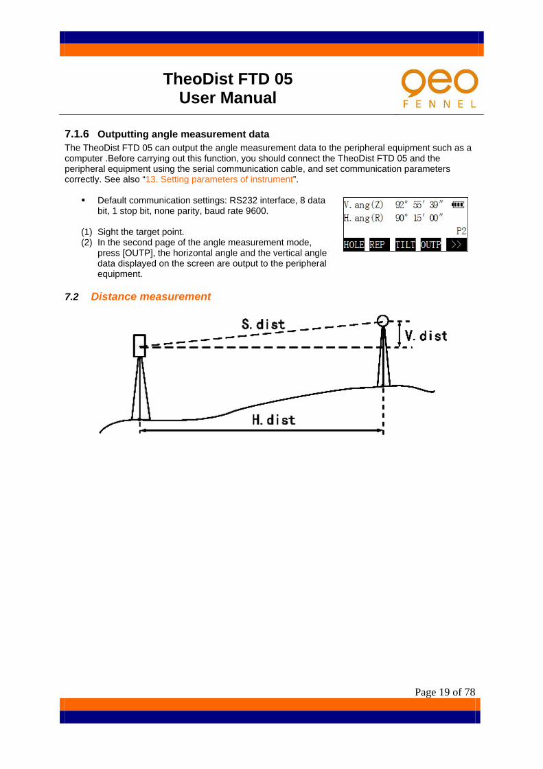
7.1.6 Outputting angle measurement data The TheoDist FTD 05 can output the angle measurement data to the peripheral equipment such as a computer .Before carrying out this function, you should connect the TheoDist FTD 05 and the peripheral equipment using the serial communication cable, and set communication parameters correctly. See also “13. Setting parameters of instrument”.
Default communication settings: RS232 interface, 8 data bit, 1 stop bit, none parity, baud rate 9600.
(1) Sight the target point. (2) In the second page of the angle measurement mode,
press [OUTP], the horizontal angle and the vertical angle data displayed on the screen are output to the peripheral equipment.
7.2 Distance measurement
TheoDist FTD 05 User Manual
Page 20 of 78
7.2.1 EDM Settings Complete the following EDM settings before the distance measurement:
Atmospheric correction factor Distance measurement mode
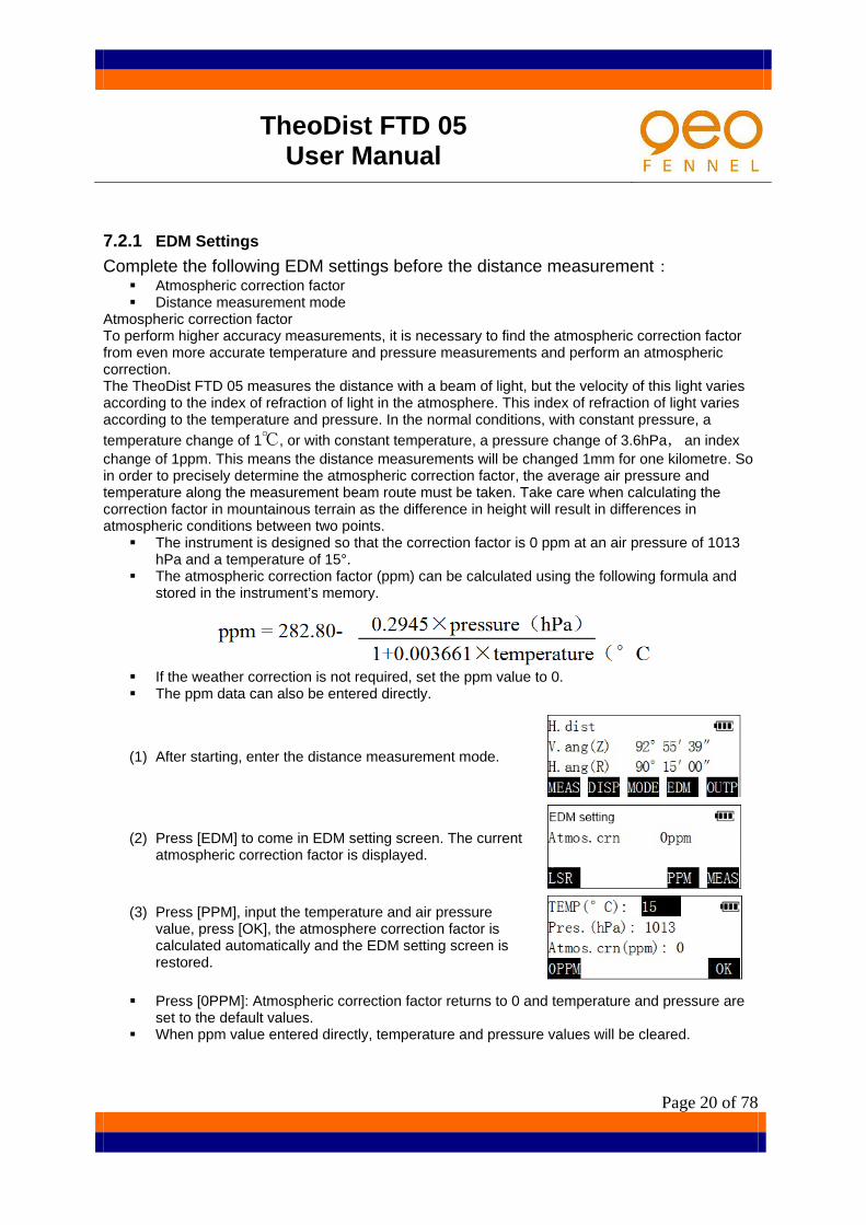
Atmospheric correction factor To perform higher accuracy measurements, it is necessary to find the atmospheric correction factor from even more accurate temperature and pressure measurements and perform an atmospheric correction. The TheoDist FTD 05 measures the distance with a beam of light, but the velocity of this light varies according to the index of refraction of light in the atmosphere. This index of refraction of light varies according to the temperature and pressure. In the normal conditions, with constant pressure, a temperature change of 1℃, or with constant temperature, a pressure change of 3.6hPa,an index change of 1ppm. This means the distance measurements will be changed 1mm for one kilometre. So in order to precisely determine the atmospheric correction factor, the average air pressure and temperature along the measurement beam route must be taken. Take care when calculating the correction factor in mountainous terrain as the difference in height will result in differences in atmospheric conditions between two points.
The instrument is designed so that the correction factor is 0 ppm at an air pressure of 1013 hPa and a temperature of 15°.
The atmospheric correction factor (ppm) can be calculated using the following formula and stored in the instrument’s memory.
If the weather correction is not required, set the ppm value to 0. The ppm data can also be entered directly.
(1) After starting, enter the distance measurement mode.
(2) Press [EDM] to come in EDM setting screen. The current atmospheric correction factor is displayed.
(3) Press [PPM], input the temperature and air pressure
value, press [OK], the atmosphere correction factor is calculated automatically and the EDM setting screen is restored.
Press [0PPM]: Atmospheric correction factor returns to 0 and temperature and pressure are set to the default values.
When ppm value entered directly, temperature and pressure values will be cleared.

TheoDist FTD 05 User Manual
Page 21 of 78
Distance measuring mode The TheoDist FTD 05 provides five kind of distance measuring mode: Fine Single measurement (Single), Fine Repeat measurement (Repetition), Fine Average measurement (Average), Rapid Repeat measurement (Rapid Rep), Tracking measurement (Tracking). Rapid Repeat measurement (approx. 0.9 seconds/time) and Tracking measurement (approx. 0.3 seconds/time) is suitable for survey of the movement target .In order to obtain the higher measurement precision, the Fine measuring mode should be selected (Fine Single mode has been set by default in factory). When Fine Average mode is set, the instrument measures the distance as the setting times and the average distance will be displayed. The number of measuring times can be defined by the user. Example 1: Set distance measuring mode as Tracking mode.
(1) Press [MODE] in the distance measurement mode to come in distance measuring mode setting screen.
(2) Press [F5] to get to the second page, press [F1] to complete the setting and exit.
TheoDist FTD 05 User Manual
Page 22 of 78
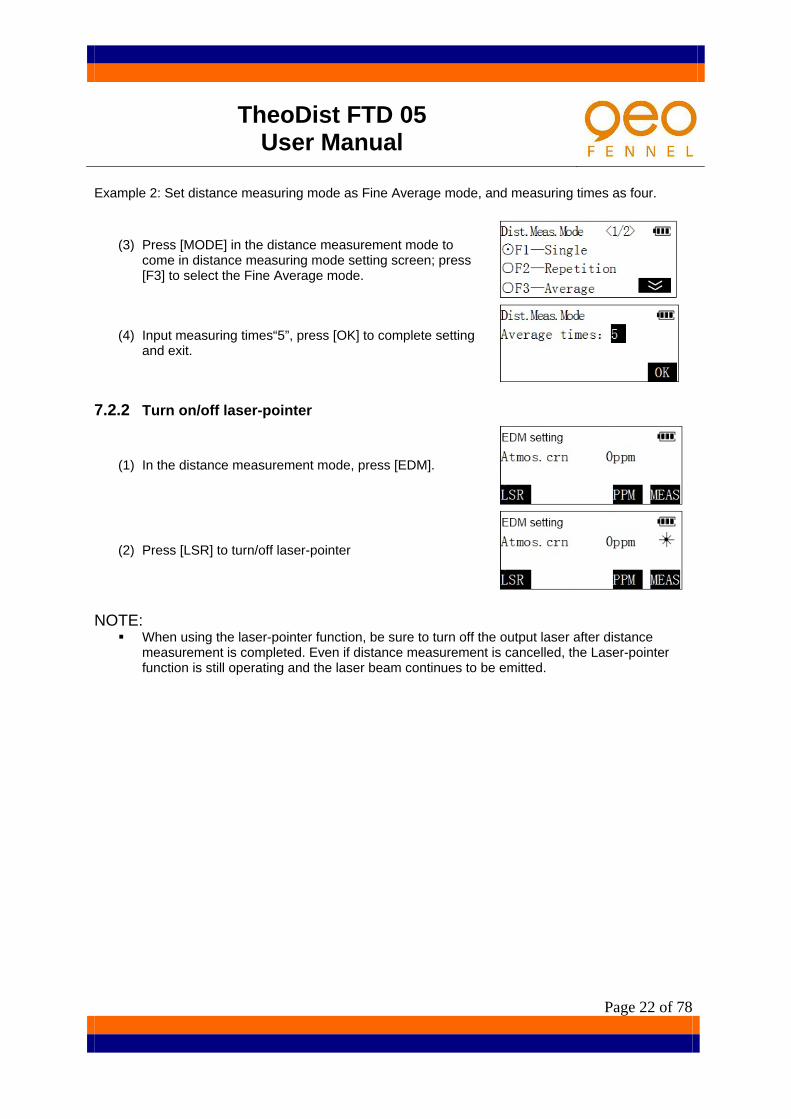
Example 2: Set distance measuring mode as Fine Average mode, and measuring times as four.
(3) Press [MODE] in the distance measurement mode to come in distance measuring mode setting screen; press [F3] to select the Fine Average mode.
(4) Input measuring times“5”, press [OK] to complete setting and exit.
7.2.2 Turn on/off laser-pointer
(1) In the distance measurement mode, press [EDM].
(2) Press [LSR] to turn/off laser-pointer
NOTE:
When using the laser-pointer function, be sure to turn off the output laser after distance measurement is completed. Even if distance measurement is cancelled, the Laser-pointer function is still operating and the laser beam continues to be emitted.

TheoDist FTD 05 User Manual
Page 23 of 78
7.2.3 Distance and angle measurement The TheoDist FTD 05 can measure both distance and angle data at the same time. Please get confirmation again before measuring:
The instrument levelled and centred well. Battery full charged. The atmosphere correction and the prism constant are set correctly. Reflective target type is selected correctly and the target centre is already collimated and
returned signal strength is suitable
(1) In the distance measurement mode, press [MEAS] or press the key [DIST] on the panel to start measurement. When measurement starts, EDM information (distance measuring mode, prism constant value, and atmospheric correction value) is displayed. After a short time, a short beep sounds, and the measured distance data, vertical angle, and horizontal angle data are displayed.
(2) Press [STOP] to stop measuring distance and return to
the distance measurement mode screen. If the single measurement mode is selected, measurement automatically stops after a single measurement. During fine average measurement, the average value of the distance is displayed and on the right side of the screen the number of the measuring times is displayed also. When the measuring times reach pre-determined number, the measurement will stop automatically.
TheoDist FTD 05 User Manual
Page 24 of 78
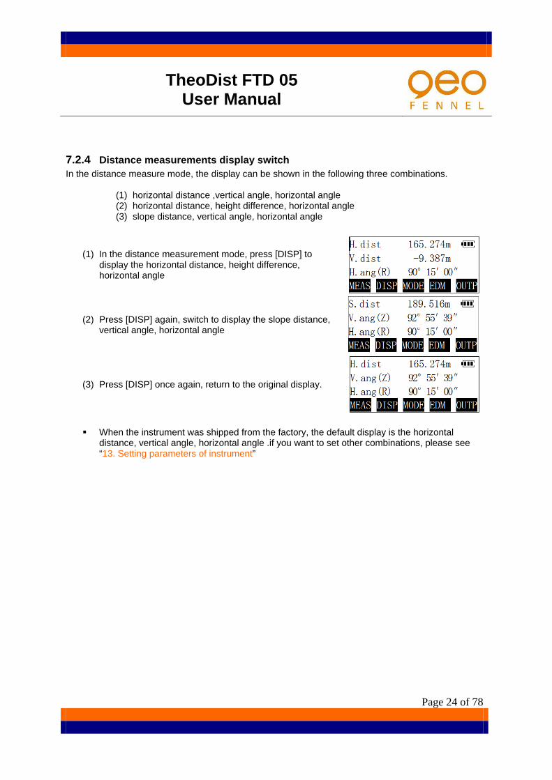
7.2.4 Distance measurements display switch In the distance measure mode, the display can be shown in the following three combinations.
(1) horizontal distance ,vertical angle, horizontal angle (2) horizontal distance, height difference, horizontal angle (3) slope distance, vertical angle, horizontal angle
(1) In the distance measurement mode, press [DISP] to display the horizontal distance, height difference, horizontal angle
(2) Press [DISP] again, switch to display the slope distance, vertical angle, horizontal angle
(3) Press [DISP] once again, return to the original display.
When the instrument was shipped from the factory, the default display is the horizontal distance, vertical angle, horizontal angle .if you want to set other combinations, please see “13. Setting parameters of instrument”

TheoDist FTD 05 User Manual
Page 25 of 78
7.2.5 Outputting distance measurement data The measured distance and angle data can be output to a peripheral equipment such as computer. Before carrying out this function, you should connect the instrument and the peripheral equipment using serial communication cable, and set communication parameters correctly, please see “13. Setting parameters of instrument”
(1) Collimate the target point, measure the distance to the point. (2) After measurement is complete, Press [OUTP] to output the measurement data to computer or
other peripheral equipment. Caution:
(3) This function only outputs the slope distance, vertical angle and horizontal angle.
7.3 Coordinate measurement By measuring the angle and the distance of target point, the TheoDist FTD 05 can get the three-dimensional coordinates of the target points (N, E, Z).
After power on, press [COORD] key on panel to enter the coordinate measurement mode.
TheoDist FTD 05 User Manual
Page 26 of 78
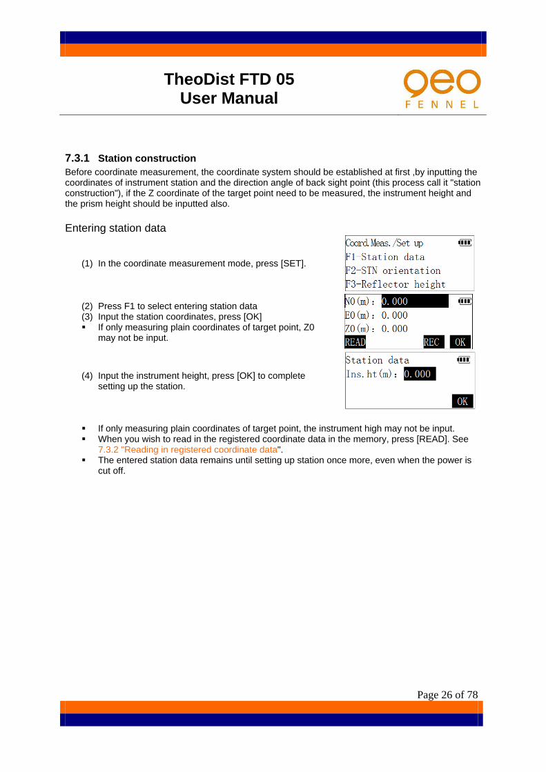
7.3.1 Station construction Before coordinate measurement, the coordinate system should be established at first ,by inputting the coordinates of instrument station and the direction angle of back sight point (this process call it "station construction"), if the Z coordinate of the target point need to be measured, the instrument height and the prism height should be inputted also. Entering station data
(1) In the coordinate measurement mode, press [SET].
(2) Press F1 to select entering station data (3) Input the station coordinates, press [OK] If only measuring plain coordinates of target point, Z0
may not be input.
(4) Input the instrument height, press [OK] to complete setting up the station.
If only measuring plain coordinates of target point, the instrument high may not be input. When you wish to read in the registered coordinate data in the memory, press [READ]. See
7.3.2 "Reading in registered coordinate data". The entered station data remains until setting up station once more, even when the power is
cut off.

TheoDist FTD 05 User Manual
Page 27 of 78
7.3.2 Reading in registered coordinate data The coordinate data stored in the instrument memory can be read in, and set as coordinates of station point, back sight point, setting-out point and so on. About the memory data managing, please see “10. Memory management”. Select A File <1/2> Input the point number you want to search for and press [OK], instrument will start searching the selected file ("Known Coord" by default) for the point. If the point is found, the coordinates of the point will be read in. Otherwise, the screen will display “PT# does not exist” and quit.
Pressing [FILE] can select another coordinates search file.
Example:Press [F2] in menu <Select A File> to select the current JOB. Note: The current JOB is a JOB that instrument used to store measurement data, it can be selected in Memory management mode or in Recording data mode
(1) Press [LIST] to list all point data in the selected file and search for the required point.
Method of operating list:
(2) Press [▲] [▼] to move the cursor up and down from line to line; (3) [F1]([1X>>])is a speed-up key, it can be set that when pressing [▲] [▼] , cursor moves
according to a line, one page, two pages, or three pages.(key caption 3X>>,6X>>,9X>> ) (4) Press [TOP] to move the cursor to the list’s beginning. (5) Press [LAST] to move the cursor to the list’s end. (6) Press [SRCH] to input the point number and search for it. (7) Press [OK] to select the record where the cursor locates.

TheoDist FTD 05 User Manual
Page 28 of 78
Direction angle setting There’s two method of setting the direction angle of the back sight point: by inputting the angle value directly or by calculating from input coordinates of the back sight point
In < Coord.Meas./Setup> menu, Press [F2] to select “STN orientation”
Inputting the direction angle
(1) In <Select Orient.Method> menu, press [F1] to select “Input BS direc.ang.”, then input the direction angle of the back sight point and press [OK].
(2) Collimate the back sight point accurately; press [OK], the horizontal angle of instrument is set as the required direction angle.

TheoDist FTD 05 User Manual
Page 29 of 78
Inputting back sight point coordinates
(3) In <Select Orient.Method> menu, press [F2] to select “Input BS pt.coord”.
(4) Input the N and E coordinate of the back sight point, and
press [OK]. When you wish to read in and set coordinate data from
memory, press [READ]. Please see 7.3.2 “Reading in registered coordinate data”.
(5) Collimate the back sight point accurately; press [CHK] to measure the back sight point.
If no need for checking, press [OK] directly.
(6) When measurement finished, the coordinate differential
between measurement result and known of the back sight point are displayed. If the error does not exceed the range permitted, press [YES] to set the direction angle and finish the orientation, otherwise, press [NO] to return to last step and re-collimate.
Inputting the height of reflective target If you wish to measure the Z coordinate of target point, the height of the reflective target must be entered. In < Coord.Meas./Setup> menu, press [F3] to select "Reflector height". Input the height of the reflector used, and then press [OK].

TheoDist FTD 05 User Manual
Page 30 of 78
7.3.2.1 D Coordinate measurement The coordinate values of the target can be found by measuring the target based on the settings of the instrument station and back sight direction angle.
The coordinate values of the target are calculated using the following formula:
N1=N0+S×sinZ×cosAz E1=E0+S×sinZ×sinAz Z1=Z0+S×cosZ+ih-fh
N0: Station N coordinate S: Slope distance ih:Instrument height E0: Station E coordinate Z: Zenith angle fh:Target height Z0: Station Z coordinate Az: Direction angle Please get confirmation again before measuring:
The instrument levelled and centred well. Battery full charged. The atmosphere correction and the prism constant are set correctly. Setting up station completed. Prism centre is already collimated and returned signal strength is suitable.
Press [MEAS] in the coordinate measurement mode, or press [COORD] key on the panel to start measurement.
When measurement finished, the coordinate value of the target is displayed.
(1) Press [MODE] to select distance measuring mode. (2) Press [EDM] to turn on laser pointer, select reflective
target type ,set the atmosphere correction and the prism constant, please see“7.2 distance measurement”
(3) When the height of the target or instrument has been changed, press [HT] to input the height of target or instrument before measuring next target.
TheoDist FTD 05 User Manual
Page 31 of 78
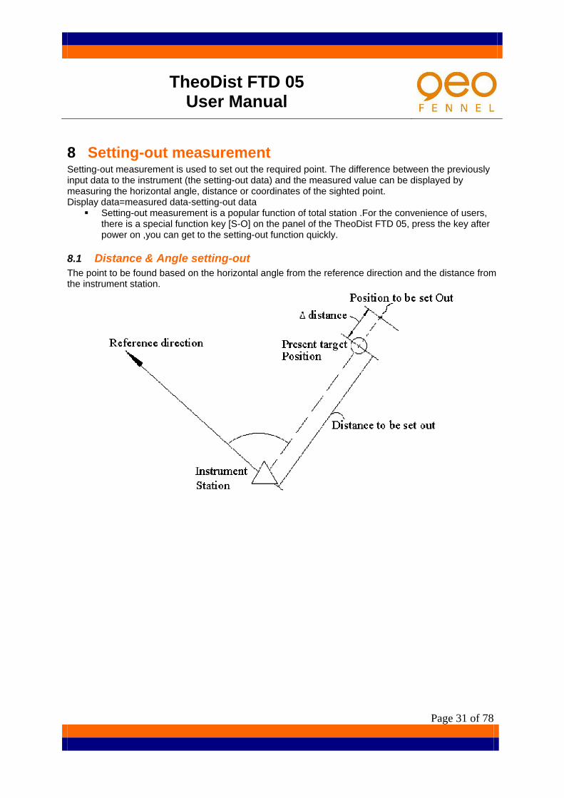
8 Setting-out measurement Setting-out measurement is used to set out the required point. The difference between the previously input data to the instrument (the setting-out data) and the measured value can be displayed by measuring the horizontal angle, distance or coordinates of the sighted point. Display data=measured data-setting-out data
Setting-out measurement is a popular function of total station .For the convenience of users, there is a special function key [S-O] on the panel of the TheoDist FTD 05, press the key after power on ,you can get to the setting-out function quickly.
8.1 Distance & Angle setting-out The point to be found based on the horizontal angle from the reference direction and the distance from the instrument station.

TheoDist FTD 05 User Manual
Page 32 of 78
(1) Press [S-O] key on the panel.
(2) Press [F1] to select "S-O distance & angle".
(3) Input the horizontal distance from the instrument station to the
position to be set out and the included angle between the reference and the point to be set out, then press [OK]
If no input in the angle input line, the system namely takes setting-out angle by the instrument current horizontal angle.
(4) Press [HSET], input the angle value of reference direction, collimate the reference direction, and then press [OK] to finish instrument orientation.
If orientation of instrument previously completed in coordinate measurement mode or angle measurement mode, this step can be left out.
(5) The horizontal angle difference between the sighted target and the point to be set out is displayed, and the arrow indicates which direction the target should be moved.
←: Looking from the station, move the prism to the left. →: Looking from the station, move the prism to the right.
(6) Rotate the top of the instrument until 0°00′00″ displayed. When the horizontal angle difference is within ±30″, “← →”will be displayed.
(7) Collimate the reflective target, press [MEAS] to start distance
measurement., the horizontal distance difference between the target and the point to be set out is displayed, and the arrow indicates which direction the target should be moved.
↓: Move the prism (reflective target) forward ↑: Move the prism (reflective target) away
Pressing [MODE] can change setting-out measuring mode. Press [EDM] to turn on laser pointer, select reflective target type ,set the atmosphere
correction and the prism constant, please see“4.2 distance measurement” When repeat measuring mode or tracking measuring mode is used for setting-out, the result
will be displayed in real-time while sighting the prism (reflective target) without pressing any key.

TheoDist FTD 05 User Manual
Page 33 of 78
(8) Move the prism (reflective target) forward and backward until the horizontal distance difference is 0m.
When the horizontal distance difference is within ±1cm, ↑↓will be displayed.
(9) Press [ESC] to finish this point setting-out measurement and continue the next point.

TheoDist FTD 05 User Manual
Page 34 of 78
8.2 Coordinate setting-out Setting-out coordinate’s measurement is used to set out the point whose coordinates is known. After inputting the coordinates of the point to be set out, the instrument calculates the setting-out horizontal angle and horizontal distance and store them in the memory. By selecting the horizontal angle and then the horizontal distance setting-out functions, the required coordinate location can be set out.
To find the Z coordinate, you had better attach the prism to a pole etc. with the same target height.
(1) In < Select S-O Mode> menu, press [F2] to select "S-O Coordinate".
(2) In< S-O Coordinate >menu, press [F1] to select "Station data", input the station coordinate and the height of instrument. Please see "7.3 coordinate measurement".
If instrument station has been set up in the previous coordinate survey, this step can be left out.
(3) In menu < S-O Coordinate >, press [F2] to select "STN Orientation", set the direction angle of the back sight point. Please see "7.3 coordinate measurement".
If direction angle has been set in the previous coordinate survey, this step can be left out.
(4) Press [F3] to select "Start S-O". Input coordinates (Np,Ep,Zp) of the setting-out point, press [S-O].

TheoDist FTD 05 User Manual
Page 35 of 78
If setting-out plane coordinates only, Zp may not be input. Pressing [PT#] can get the setting-out point coordinate in memory by inputting the setting-out
point number. Please see "7.3.2 Coordinate measurement/Reading in registered coordinate data".
Press [REC] to record the input coordinate data into memory.
(5) Measure and enter the height of the reflective target, press [OK]. If setting-out plane coordinates only, this step can be left
out.
(6) Following the same steps mentioned in “8.1 Distance & Angle setting-out”, complete the plane coordinates setting-out.
(7) Press [CRD] to record the coordinates of the measuring point.
(8) Pressing [DIFF] can see the difference between the current coordinate and the setting-out coordinate.
(9) Observe the height difference between the target and the
required point which displayed on the third line.
:move the prism upward.
:move the prism downward. Move the prism upward and downward until the value displayed on the fourth line is 0m.
When the height difference approach 0m,two arrows will be displayed When all the values displayed on the screen are 0, then the setting-out point is just located at the bottom of the pole that the prism attached to
(10) Press [DIFF] to see the difference between the current coordinate and the setting-out coordinate. Press [ESC] to finish this point setting-out measurement and continue the next point.
Distance scale correction in the coordinates setting-out measurement. The TheoDist FTD 05 can carry out the distance correction of Average Elevation and Projection by setting a scale factor .In the second page of menu <S-O Coordinate > ,Press [F1] to select "Scale correction", and enter correction factor.
Distance scale correction also can be set in parameter setting mode, please see "13. Setting parameter of instrument".
For details about distance scale correction, please see "13. Setting parameter of instrument".
TheoDist FTD 05 User Manual
Page 36 of 78
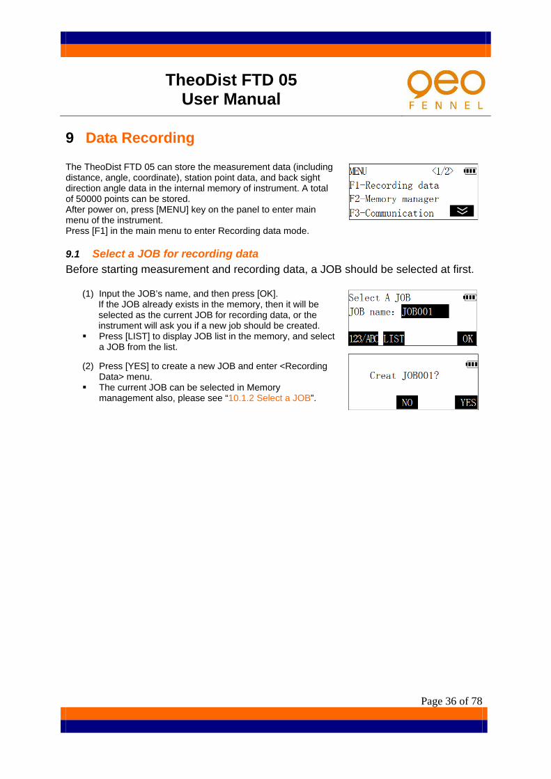
9 Data Recording The TheoDist FTD 05 can store the measurement data (including distance, angle, coordinate), station point data, and back sight direction angle data in the internal memory of instrument. A total of 50000 points can be stored. After power on, press [MENU] key on the panel to enter main menu of the instrument. Press [F1] in the main menu to enter Recording data mode.
9.1 Select a JOB for recording data Before starting measurement and recording data, a JOB should be selected at first.
(1) Input the JOB’s name, and then press [OK]. If the JOB already exists in the memory, then it will be selected as the current JOB for recording data, or the instrument will ask you if a new job should be created.
Press [LIST] to display JOB list in the memory, and select a JOB from the list.
(2) Press [YES] to create a new JOB and enter <Recording Data> menu.
The current JOB can be selected in Memory management also, please see “10.1.2 Select a JOB”.

TheoDist FTD 05 User Manual
Page 37 of 78
9.2 Set instrument station and record the station data Station point and direction angle data are the same in data recording mode and normal coordinate measurement mode, and can be entered or changed.
(1) Press [F1] in <Recording Data> menu to select “Station data”.
(2) Input coordinates of the current station, then press [REC].
(3) Input point number, code, height of the instrument, then press [OK] to store the station data into memory.
Press [JOB]; re-select a JOB to store data. Press [VIEW] to view data stored in the current JOB.
please see “9.6 Review the data in the current JOB” When editing code, the code registered in memory can be
recalled and read in.
(4) Press [OK] to confirm the station data, return to <Recording Data> menu.

TheoDist FTD 05 User Manual
Page 38 of 78
9.3 Set back sight direction angle and record the direction angle data
(1) Press [F2] in <Recording Data> menu to select "STN orientation".
(2) According to the same steps described in"7.3.1 Station construction ", input back sight direction angle or input back sight point coordinates, then the instrument prompt to collimate the back sight point.
(3) Collimate back sight point accurately, press [REC]
(4) Input point number, code, prism height, press [OK] to store the direction angle data into memory.
(5) Press [OK] to finish orientation, return to <Recording Data> menu

TheoDist FTD 05 User Manual
Page 39 of 78
9.4 Record measurement data (1) Press【F3】 in <Recording Data> menu to start measurement and recording data.
Press [DIST] to measure and record distance data. Press [ANG] to measure and record angle data. Press [CRD] to measure and record coordinate data.
Following is an example of recording coordinate data.
(2) Collimate the target, press [CRD] or press [COORD] key on the panel to start coordinate measurement.
(3) The measurement results are displayed when measurement finished.
If the target point situated in which a prism cannot be installed directly or cannot be sighted, press [OFFS] to calculate the data of the target point by carrying out Offset-Measurement program. Please see “12.2 Offset-Measurement”.
(4) Press [REC] to record the measured data marked “*”. Input point number, code, reflector height, and then press [OK] to store the coordinate data in memory.
(5) Continue measuring next point.
Distance data include slope distance, vertical angle, horizontal angle;
Coordinate data include N, E, Z coordinates; Angle data include vertical angle, horizontal angle.
(6) Press [ALL] to perform measurement and automatically record the results. In this case, the point number is the last point number add one, the code and prism height remain the same. When the measurement results recording finished, the results will be displayed for two seconds, then the screen of last step is restored.

TheoDist FTD 05 User Manual
Page 40 of 78
9.5 Configuration of data recording The below options can be set in data recording mode:
(1) Sequence of measuring and recording The sequence can be set as "measure first, then edit" , means that measure the target point first, then input point number, code, prism height(this is default setting by factory); or "edit first, then measure" , means that input point number, code, prism height first, then measure the target point and record the data.
(2) Automatic coordinate calculation When this option is set, the instrument will automatically calculate coordinate of target point and store it to the JOB after measuring and recording distance data. It’s very useful in traverse measurement.
(3) Select distance measuring mode Select a distance measuring mode special for data recording mode.
Example for setting “automatic coordinate calculate” option:
(1) In the second page of <Recording Data> menu, press [F2] to enter the configuration menu.
(2) Press [F2] to select "Auto coord.calc". (3) Press [F2] to enable the function, and then press [ESC] to
return.
The settings of option will remain until being changed once more even when power is cut off.
9.6 Reviewing the data in the current JOB It is possible to display the data recorded in the current JOB in data recording mode.
(1) Enter the second page of <Recording Data> menu.
(2) Press [F3] to select “View JOB”, then list of the data stored in the current JOB is displayed.
(3) Move cursor to select the point number to be displayed
and press [VIEW]. Details of the point data are displayed. For more about the operation, please see "10.1.1 Review and delete record in JOB"

TheoDist FTD 05 User Manual
Page 41 of 78
9.7 Measure and record data in basic measurement mode by pressing one key
For the convenience of users, there is a [USER] key on the panel of the TheoDist FTD 05, whose function can be defined by user (Please see "13.3 define function of the USER key"), default function is set as "measure and record data" by factory, the following explain how to measure and record data quickly by press [USER] key in basic measurement mode.
(1) In basic measurement mode, collimate the target point.
(2) Press [USER] key, begin measuring the target point.
(3) When measuring finished, point number of the target and name of the current JOB will be displayed 2 seconds, then a short beep will sound, the measured data is stored in the memory automatically. If pressing [EDIT] on this screen in 2 seconds, it is possible to edit the point number, code, prism height and select another JOB. Please see "9.4 recode measurement data".
(4) Point number will add one automatically; continue to measure the next point.

TheoDist FTD 05 User Manual
Page 42 of 78
10 Memory management After power on, press [MENU] key on the panel to enter the main menu, select "F2- Memory Manager" to enter memory management mode. In this mode, you can perform the function related to JOB and data in instrument's memory.
10.1 JOB manager Press [F1] to select "JOB" in <Memory Manager> menu, the list of JOB in the memory is displayed on the screen, including JOB name, the number of data items already stored in the JOB.
The JOB marked with “*” is the current job selected to store data.
Method of operating JOB list:
Press [▲] [▼] to move the cursor up and down from line to line; [F1]([1X>>])is a speed-up key, It can be set that when pressing [▲] [▼] , cursor moves
according to a line, one page, two pages, or three pages.(key caption 3X>>,6X>>,9X>> ) Press [TOP] to move the cursor to the list’s beginning. Press [LAST] to move the cursor to the list’s end. Press [SRCH] to input the JOB name and search for it. Press [OPTN] to enter the menu of JOB manager option.
TheoDist FTD 05 User Manual
Page 43 of 78
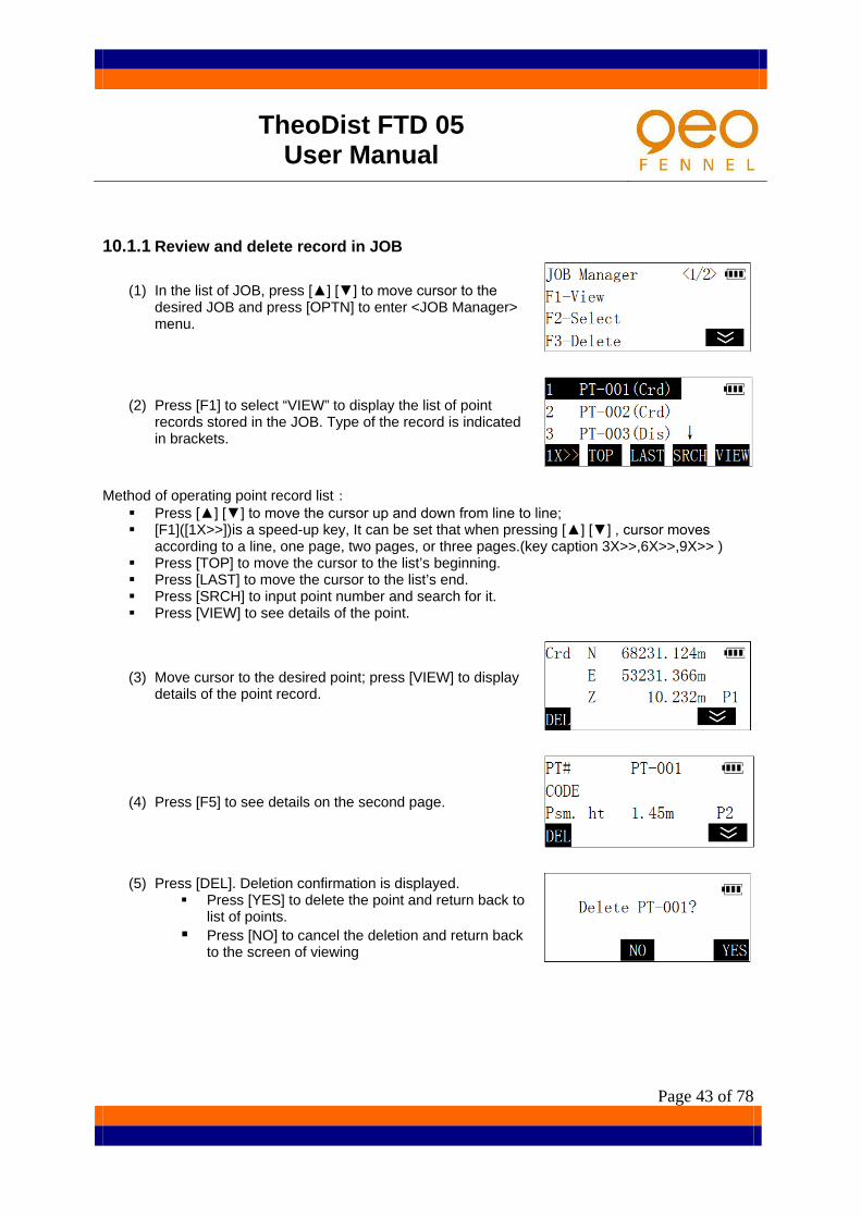
10.1.1 Review and delete record in JOB
(1) In the list of JOB, press [▲] [▼] to move cursor to the desired JOB and press [OPTN] to enter <JOB Manager> menu.
(2) Press [F1] to select “VIEW” to display the list of point records stored in the JOB. Type of the record is indicated in brackets.
Method of operating point record list:
Press [▲] [▼] to move the cursor up and down from line to line; [F1]([1X>>])is a speed-up key, It can be set that when pressing [▲] [▼] , cursor moves
according to a line, one page, two pages, or three pages.(key caption 3X>>,6X>>,9X>> ) Press [TOP] to move the cursor to the list’s beginning. Press [LAST] to move the cursor to the list’s end. Press [SRCH] to input point number and search for it. Press [VIEW] to see details of the point.
(3) Move cursor to the desired point; press [VIEW] to display details of the point record.
(4) Press [F5] to see details on the second page.
(5) Press [DEL]. Deletion confirmation is displayed. Press [YES] to delete the point and return back to
list of points. Press [NO] to cancel the deletion and return back
to the screen of viewing

TheoDist FTD 05 User Manual
Page 44 of 78
10.1.2 Select a JOB The current JOB can be selected in JOB manager for recording measurement data later.
(1) In the list of JOB, press [▲] [▼] to move cursor to the desired JOB and press [OPTN] to enter <JOB Manager> menu.
(2) Press [F2] to select the JOB and return back to JOB list.
10.1.3 Delete a JOB
(1) In the list of JOB, press [▲] [▼] to move cursor to the JOB you want to delete, and press [OPTN] to enter <JOB Manager> menu.
(2) Press [F2]. Deletion confirmation is displayed. Press [YES] to delete the JOB and return. Press [NO] to cancel the deletion and return.
TheoDist FTD 05 User Manual
Page 45 of 78
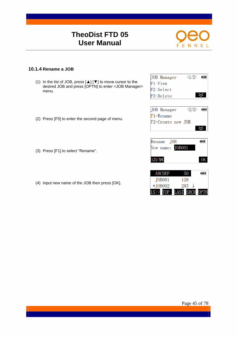
10.1.4 Rename a JOB
(1) In the list of JOB, press [▲] [▼] to move cursor to the desired JOB and press [OPTN] to enter <JOB Manager> menu.
(2) Press [F5] to enter the second page of menu.
(3) Press [F1] to select “Rename”.
(4) Input new name of the JOB then press [OK].

TheoDist FTD 05 User Manual
Page 46 of 78
10.2 Management of Known Coord "Known Coord" is a special file of the TheoDist FTD 05 that used to store and manage coordinate data of known points, the difference from normal JOB is that it is only used to store known coordinate data, not measurement data. It is suitable to store common coordinate data that often be used, and can be read in by user conveniently in different projects.
10.2.1 Input coordinates of known point
(1) Press [F2] to select “Known Coord” in <Memory Manager> menu to enter <Known Coord> menu.
(2) Press [F1] to select “Input coord”.
(3) After inputting point number, press [OK].
(4) Enter coordinates of known point then press [OK].The coordinate data is recorded in the memory and screen in step 3 is restored.
(5) Point number add one automatically; continue to enter
coordinates of the next point. Repeat the steps above to input coordinate data of all known points. Press [ESC] on the panel to finish input and return to <Known Coord> menu.
In the second page of <Memory Manager> menu, select “Input coordinate” can inputting known point coordinates into a JOB, the procedure is the same as described above.

TheoDist FTD 05 User Manual
Page 47 of 78
10.2.2 Review and delete known point coordinate data All the known point coordinate data stored in the memory can be reviewed and the data no more needed can be deleted.
(1) Press [F2] to select “Known Coord” in <Memory Manager> menu to enter <Known Coord> menu.
(2) Press [F2] to select “List and view”, the list of known point of memory is displayed.
Method of list operation, please see "10.1.1 Review and delete record in JOB".
(3) Move cursor to the desired point; press [VIEW] to display details of the point.
(4) Press [DEL]. Deletion confirmation is displayed.
Press [YES] to delete the point and return back to the list of known points.
Press [NO] to cancel the deletion and return back to the screen of viewing detail of the point.
10.2.3 Delete all known point This operation will delete the entire known point coordinate in the memory at once.
(1) Press [F2] to select “Known Coord” in <Memory Manager> menu to enter <Known Coord> menu.
(2) Press [F3] to select “Clear”, a confirmation screen is viewed.
(3) Press [YES] to confirm the operation and all the known point will be deleted.

TheoDist FTD 05 User Manual
Page 48 of 78
10.3 Code manager Code can be entered in the memory of instrument in advance. When recording instrument station or measurement data, these codes can be recalled and read in.
10.3.1 Input code
(1) Press [F3] to select “Code” in <Memory Manager> menu to enter <Code> menu.
(2) Press [F1] to select “Input code”.
(3) Input code then press [OK], the code is stored in memory and the screen is restored. Press [ESC] key on the panel to finish inputting and return back to <Code> menu.
10.3.2 Review and delete codes
(1) Press [F3] to select “Code” in <Memory Manager> menu to enter <Code> menu.
(2) Press [F2] to select "List", the code list is displayed on the screen.
(3) Press [▲] [▼] to move cursor to code you want to delete, then press [DEL], the code will be deleted.
(4) Press [ESC] to finish this procedure and return to <Code>
menu. Press [F3], selecting “Clear” in <Code> menu can delete
all code in memory.

TheoDist FTD 05 User Manual
Page 49 of 78
10.4 Display status of memory
(1) Enter the second page of memory management mode menu.
(2) Press [F2] to select “Memory status”, the current status of
memory will display on the screen. JOBs: The number of JOB files in the memory. Known coords: The number of known points in the
memory. Recs free: The number of the free record blocks can be
used to store data in the memory. The progress bar show the status of the memory is
occupied.
10.5 Format memory Operation of formatting memory will delete all data in memory including all JOBS, Known Coord file and codes, and resume the memory to factory status. Please take care to use this function to avoid loss of useful data.
(1) Enter the second page of memory manage mode menu.
(2) Press [F3] to select “Format memory”. A confirmation screen is viewed.
Press [NO] to abort the operation. Press [YES] to delete all data in memory.

TheoDist FTD 05 User Manual
Page 50 of 78
11 Data communication The measurement data of JOB stored in memory of instrument can be transferred to a PC and the known coordinate data also can be transferred from PC to the internal memory of instrument. Press [MENU] key on the panel after power on to enter main menu, then select "F3-Communication" to enter data communication mode.
11.1 Settings of communication TheoDist FTD 05 serial communication protocol: 8 data bit, 1 stop bit, none parity, baud rate
1200、2400、4800、9600、19200 bps optional (default 9600 bps). Before starting communication with PC, please insure the parameters of communication of
each other are set correctly and the same, otherwise the communication will be failed. Follow steps below, the communication baud rate can be changed:
Example: Set baud rate as “4800 bps”
(1) Press [F3] to select "Comms setting" in <Communication> menu. The current setting is displayed.
(2) Press [F5] to enter the first page of <Comms Setting> menu.
(3) Press [F3] to select“4800 bps”.
(4) Press [ESC] to return to <Communication> menu. The baud rate can be set in parameters setting mode
also, please see "13.Setting parameters of instrument".

TheoDist FTD 05 User Manual
Page 51 of 78
11.2 Send JOB data (1) Connect PC and the TheoDist FTD 05 with communication cable. Run the total station
communication program on PC, click【COMMUNICATION】, 【RECEIVE】, set the parameters of communication correctly, then click【OK】.
(2) Press [F1] to select "Send data" in <Communication> menu, the JOB list of memory is displayed.
(3) Press [▲] [▼], move cursor to the JOB that you want to
send, press [OK] to select the JOB, then <Select data format> menu appears.
Point coord: Convert known point coordinate data, coordinate measurement data, station data stored in memory to simple format (point number, code, N, E, Z).
Raw data: Raw measurement data stored in memory.
(4) e.g. Press [F1] to select "Point coord", instrument begin transferring the JOB data to PC.
Press [STOP] to stop the transferring.
(5) When transferring complete, the JOB list screen is restored. You can select and send next JOB.

TheoDist FTD 05 User Manual
Page 52 of 78
11.3 Receive known point coordinate data (1) Connect PC and the TheoDist FTD 05 with communication cable, run total station
communication program on PC, edit coordinate data, then click【COMMUNICATION】,【SEND】, set parameter of communication, then click【OK】.
(2) Press [F2] to select "Receive data" in <Communication> menu, the file used to receive data is displayed. Default file used to receive known point coordinate data is "Known Coord" file, and waiting for confirmation.
Pressing [FILE] can change file or create a new JOB used to receive known point data.
(3) E.g. select creating a new JOB used to receive known point coordinate data. Press [FILE] to enter <Select A File> menu.
(4) Press [F3] to select "New JOB".
(5) Input JOB name, then press [OK], new JOB will be created and return to screen of last step.
(6) Press [YES] to start receiving data from PC. The number
means amount of data received. Press [STOP] to stop transferring.
TheoDist FTD 05 User Manual
Page 53 of 78
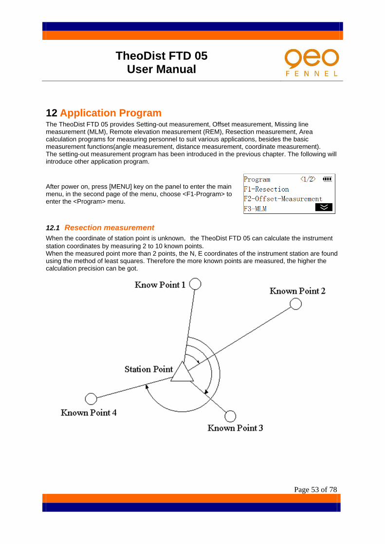
12 Application Program The TheoDist FTD 05 provides Setting-out measurement, Offset measurement, Missing line measurement (MLM), Remote elevation measurement (REM), Resection measurement, Area calculation programs for measuring personnel to suit various applications, besides the basic measurement functions(angle measurement, distance measurement, coordinate measurement). The setting-out measurement program has been introduced in the previous chapter. The following will introduce other application program.
After power on, press [MENU] key on the panel to enter the main menu, in the second page of the menu, choose <F1-Program> to enter the <Program> menu.
12.1 Resection measurement When the coordinate of station point is unknown,the TheoDist FTD 05 can calculate the instrument station coordinates by measuring 2 to 10 known points. When the measured point more than 2 points, the N, E coordinates of the instrument station are found using the method of least squares. Therefore the more known points are measured, the higher the calculation precision can be got.

TheoDist FTD 05 User Manual
Page 54 of 78
12.1.1 Calculating the station coordinate by measuring 2 known points (1) In <Program> menu, press [F1] to select "Resection ".
Resection procedure will prompt "Input known pt1". Press [PT#] to read in registered coordinate data in
memory by entering the point number of known point. Please see"7.3.2 Coordinate measurement /Reading in registered coordinate data"
Press [REC] to record input data into memory.
(2) Input the coordinates of the first known point and press [OK]. The procedure request inputting the reflector height of known point 1.
If only surveying plane coordinates of the station, this step can be left out.
(3) Measure and input the height of the reflector, then press [OK]. Procedure prompts for measuring known point 1.
Press [MODE] to select distance measuring mode. Press [EDM] to turn on laser pointer, select reflective
target type ,set the atmosphere correction and the prism constant, please see“7.2 distance measurement”
(4) Collimate the known point 1; press [MEAS] to start measuring distance value and angle value of the known point 1. After measurement is complete, the results are displayed.
(5) If the data was mistake, pressing [CE] may observe the
known point 1 again. Or press [OK] to finish inputting and measuring the known point 1.
Then procedure will prompt "Input known pt2". Repeat the steps above to finish inputting and measuring the second known point.
(6) When the two known points have been input and measured, the list of the known points is displayed.
Press [▲] [▼] to move the cursor up and down and select the known point. Press [ADD] to add a known point for resection. Press [REOBS] to re-enter or re-observe the selected known point. Press [CALC] to start resection calculation Press [Y/N] to make the known point selected joining for calculation or not.

TheoDist FTD 05 User Manual
Page 55 of 78
(7) Press [CALC]. The instrument station coordinates are calculated and displayed.
Press [REC] to store the results in the memory Press [SET] to accept the calculated results as the new
station coordinates.
(8) Press [SET] to set the instrument station coordinates, then the direction angle of the last known point as the back sight point is calculated and displayed.
Pressing [SKIP] can leave out this step.
(9) Collimate the last known point, press [SET] to set the direction angle and finish setting up station, and then exit.

TheoDist FTD 05 User Manual
Page 56 of 78
12.1.2 Calculating the station coordinate by measuring multiple known points
(1) According to"12.1.1 calculating the station coordinate by measuring 2 known points",input and measure two known points, and then the list of the known points is displayed.
(2) Press [ADD] to input and measure the other points in the same way as described above.
(3) Repeat the steps until all required known points are input and measured.
(4) Press [CALC] to calculate the coordinates of the instrument station.
(5) Press [ERR]. The standard deviation which describes the measurement accuracy is displayed.
Press [ESC] to return to the previous screen.
Caution:
In some cases it is impossible to calculate the coordinates of an unknown point if the unknown point and three or more known points are arranged on the edge of a single circle. If it occurs, try to take one of the following: a) Move the instrument station as close as possible to the centre of the triangle. b) Observe one more known point that is not on the circle. In some cases it is impossible to calculate the coordinates of the instrument station if the included angle between the known points is too small. It is difficult to imagine that the longer the distance between the instrument station and the known points, the narrower the included angle between the known points. Be careful because the points can easily be aligned on the edge of a single circle.
12.2 Offset measurement Offset measurement is performed in order to find a point where a target cannot be installed directly or to find the distance and angle to a point which cannot be sighted. It is possible to find the distance and angle to a point you wish to measure by installing the target at a location a little distance from the target point and measuring the distance and angle from the surveying point to the offset point. And if instrument station has been set up, the coordinates of the target point can be calculated.

TheoDist FTD 05 User Manual
Page 57 of 78
There are two offset-measuring methods: distance offset and angle offset.
12.2.1 Distance offset measurement Finding it by entering the horizontal distance from the target point to the offset point
When the offset point is positioned to the left or right of the target point, make sure the angle
formed by lines connecting the offset point to the target point and to the instrument station is almost 90°. When the offset point is positioned in front of or behind the target point, install the offset point on a line linking the instrument station with the target point.

TheoDist FTD 05 User Manual
Page 58 of 78
(1) In <Program> menu, press [F2] to select “Offset
measurement”, the procedure prompts measuring the offset point first.
Press [MODE] to select distance measuring mode. Press [EDM] to turn on laser pointer, select reflective
target type ,set the atmosphere correction and the prism constant, please see“4.2 distance measurement”
(2) Collimate the offset point, press [MEAS].The instrument starts measuring the offset point and display the result.
(3) Press [OK]. Procedure request selecting offset mode.
(4) Press [F1] to select "Distance". Procedure request
inputting the direction of offset point and horizontal distance from the target point to the offset point.
Press [MEAS] to re-observe the offset point.
(5) Press [DIREC] to switch the direction of the offset point. ↑Forward: Closer than the target point. ↓Rear: Beyond the target point. ←Left: On the left of the target point. →Right: On the right of the target point.
(6) Example: if the offset point on the left of the target point.
Press [F3] twice to select "Left".
(7) Input the horizontal distance between the offset point and target point.
Press [OK], the distance and angle of the target point are calculated Press [REC] to record the results. Press [CRD] to switch the screen display from distance
values to coordinates values. Press [CE] to return to step 4, re-input the distance and
angle of the offset point. Press [OK] to finish the offset measurement.
TheoDist FTD 05 User Manual
Page 59 of 78
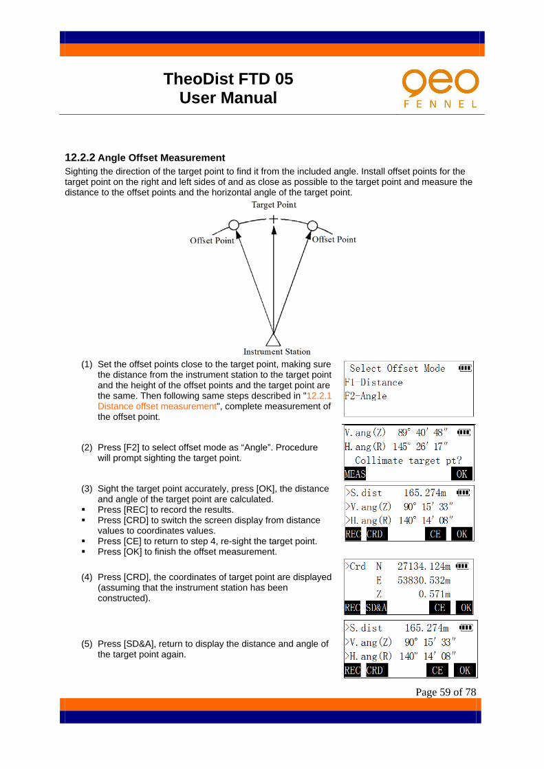
12.2.2 Angle Offset Measurement Sighting the direction of the target point to find it from the included angle. Install offset points for the target point on the right and left sides of and as close as possible to the target point and measure the distance to the offset points and the horizontal angle of the target point.
(1) Set the offset points close to the target point, making sure
the distance from the instrument station to the target point and the height of the offset points and the target point are the same. Then following same steps described in "12.2.1 Distance offset measurement", complete measurement of the offset point.
(2) Press [F2] to select offset mode as “Angle”. Procedure will prompt sighting the target point.
(3) Sight the target point accurately, press [OK], the distance
and angle of the target point are calculated. Press [REC] to record the results. Press [CRD] to switch the screen display from distance
values to coordinates values. Press [CE] to return to step 4, re-sight the target point. Press [OK] to finish the offset measurement.
(4) Press [CRD], the coordinates of target point are displayed (assuming that the instrument station has been constructed).
(5) Press [SD&A], return to display the distance and angle of the target point again.

TheoDist FTD 05 User Manual
Page 60 of 78
12.3 Missing line measurement Missing line measurement (MLM) is used to measure the slope distance, horizontal distance, and horizontal angle to a target from the target which is the reference (starting point) without moving the instrument.
It is possible to change the last measured point to the next starting position. When measuring the height difference of two or more points attach the prism to a pole etc.
and make all the targets at the same height. Measurement result can be displayed as the gradient between two points.

TheoDist FTD 05 User Manual
Page 61 of 78
12.3.1 Measuring the distance between 2 or more points
(1) In <Program> menu, press [F3] to select the missing line measurement. The procedure prompts measuring the starting point.
Press [MODE] to select distance measuring mode. Press [EDM] to turn on laser pointer, select reflective target type ,set the atmosphere
correction and the prism constant, please see“7.2 distance measurement”
(2) Sight the starting point, press [MEAS]. The instrument starts to measure the starting point and display the result after measurement completed.
(3) Press [OK] to confirm the measurement result. The procedure prompts measuring the end point.
(4) When the measurement is complete, slope distance, horizontal distance and height difference between the end point and the starting point are calculated and displayed.
(5) Press [SD/%], the gradient between two points is displayed on the first line of screen.
Press [1-PT] to re-observe the starting point.
(6) Press [SD/%] once more, return to display the slope distance.
(7) Sight the next target point and press [2-PT] to observe it. Slope distance, horizontal distance and height difference between multiple points and the starting point can be measured by this way.

TheoDist FTD 05 User Manual
Page 62 of 78
12.3.2 Changing the starting point It is possible to change the last measured point to the next starting position.
(1) Observe the starting position and target following steps 1 to 3 in "12.3.1 Measuring the distance between 2 or more points".
(2) After measuring the targets, press [MOVE].
(3) Press [YES] to change the last measured point to the next starting position. Perform MLM following steps 2 to 3 in "12.3.1 Measuring the Distance between 2 or more points".

TheoDist FTD 05 User Manual
Page 63 of 78
12.4 Remote elevation measurement Remote elevation measurement (REM) is used to measure the height to a point where a reflective target cannot be directly installed such as power lines, bridge and overhead cables, etc.)
The height of the target is calculated using the following formula
The TheoDist FTD 05 has two REM measurement modes: use a reflective target height or not use. When using a reflective target height, the REM will select the reflective target as a reference point. If no reflective target height is used, the REM will select ground point of the reflective target as a reference point.
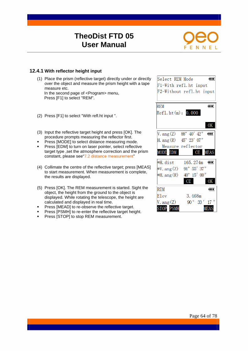
TheoDist FTD 05 User Manual
Page 64 of 78
12.4.1 With reflector height input (1) Place the prism (reflective target) directly under or directly
over the object and measure the prism height with a tape measure etc.
In the second page of <Program> menu, Press [F1] to select "REM".
(2) Press [F1] to select "With refl.ht input ".
(3) Input the reflective target height and press [OK]. The
procedure prompts measuring the reflector first. Press [MODE] to select distance measuring mode. Press [EDM] to turn on laser pointer, select reflective
target type ,set the atmosphere correction and the prism constant, please see“7.2 distance measurement”
(4) Collimate the centre of the reflective target; press [MEAS] to start measurement. When measurement is complete, the results are displayed.
(5) Press [OK]. The REM measurement is started. Sight the
object, the height from the ground to the object is displayed. While rotating the telescope, the height are calculated and displayed in real time.
Press [MEAD] to re-observe the reflective target. Press [PSMH] to re-enter the reflective target height. Press [STOP] to stop REM measurement.

TheoDist FTD 05 User Manual
Page 65 of 78
12.4.2 Without reflective target height input
(1) Place the reflective target directly under or directly over the object. In the second page of <Program> menu, press [F1] to select "REM".
(2) Press [F2] to select "Without refl.ht input".
(3) Collimate the centre of the reflective target; press [MEAS] to start measurement. When measurement is complete, the results are displayed.
(4) Press [OK] to confirm the measurement results. The procedure prompts collimating the ground point of the reflective target.
(5) Collimating the ground point of the reflective target and
press [OK]. The REM measurement is started. Sight the object, the height from the ground to the object is displayed. While rotating the telescope, the height are calculated and displayed in real time.
Press [GRND] to re-sight point on the ground.
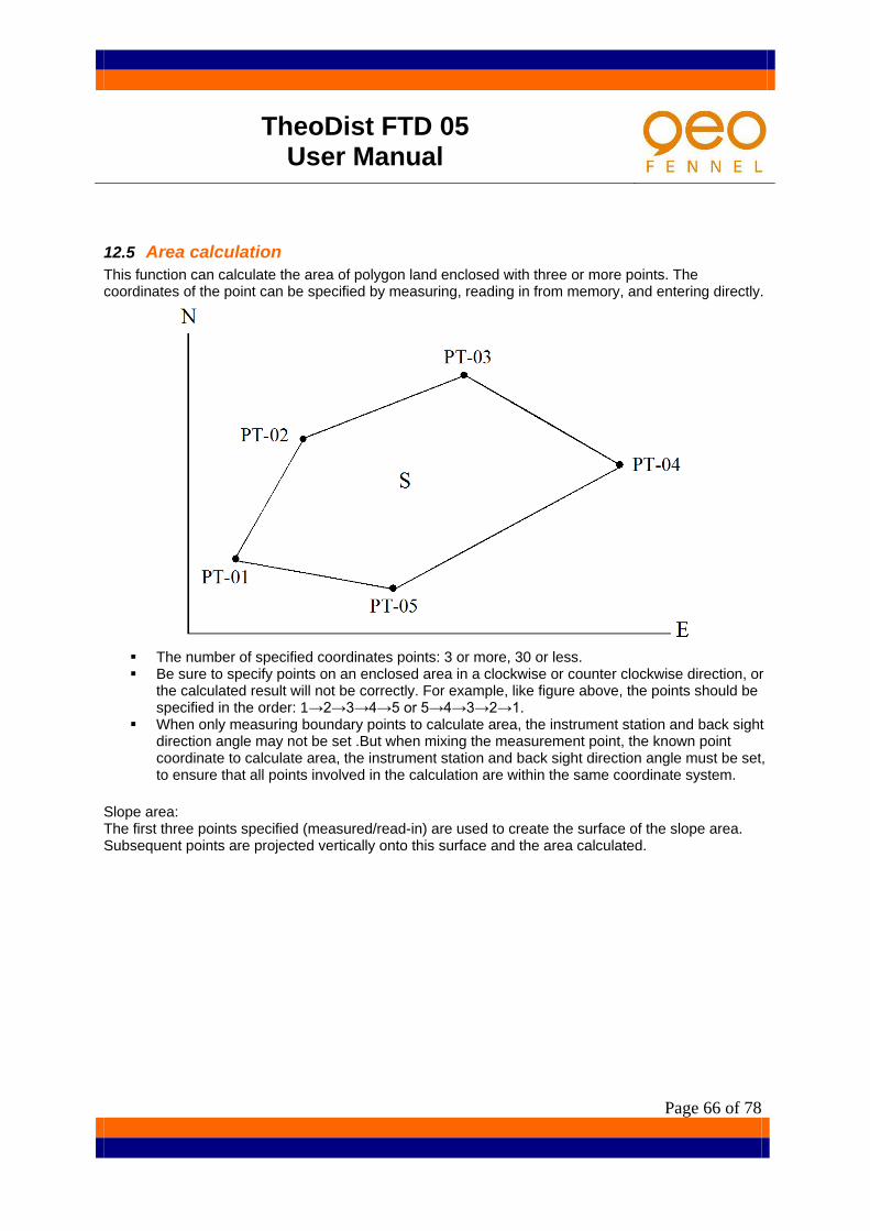
TheoDist FTD 05 User Manual
Page 66 of 78
12.5 Area calculation This function can calculate the area of polygon land enclosed with three or more points. The coordinates of the point can be specified by measuring, reading in from memory, and entering directly.
The number of specified coordinates points: 3 or more, 30 or less. Be sure to specify points on an enclosed area in a clockwise or counter clockwise direction, or
the calculated result will not be correctly. For example, like figure above, the points should be specified in the order: 1→2→3→4→5 or 5→4→3→2→1.
When only measuring boundary points to calculate area, the instrument station and back sight direction angle may not be set .But when mixing the measurement point, the known point coordinate to calculate area, the instrument station and back sight direction angle must be set, to ensure that all points involved in the calculation are within the same coordinate system.
Slope area: The first three points specified (measured/read-in) are used to create the surface of the slope area. Subsequent points are projected vertically onto this surface and the area calculated.

TheoDist FTD 05 User Manual
Page 67 of 78
12.5.1 Calculate area from measuring boundary point
(1) In the second page of <Program> menu, press [F2] to select "Area calculation".
(2) Sight the first boundary point and press [MEAS] to start measurement. When measurement finished, the measured values are displayed.
(3) Press [OK].
(4) Following the same steps as mentioned above, complete
measuring other boundary points in clockwise or counter-clockwise direction. When the number of the measured points is enough at least 3, the area of the polygon enclosed with these points can be calculated.
Pts.: number of specified points. (5) Press [CALC] to calculate and display the area of the
polygon enclosed with the boundary points. H.area : horizontal area S.area: slope area
[ESC] to return to the boundary point list. Press [OK] to finish the area calculation function.
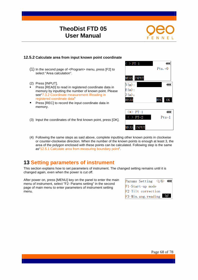
TheoDist FTD 05 User Manual
Page 68 of 78
12.5.2 Calculate area from input known point coordinate
(1) In the second page of <Program> menu, press [F2] to select "Area calculation".
(2) Press [INPUT]. Press [READ] to read in registered coordinate data in
memory by inputting the number of known point. Please see“7.3.2 Coordinate measurement /Reading in registered coordinate data”
Press [REC] to record the input coordinate data in memory.
(3) Input the coordinates of the first known point, press [OK].
(4) Following the same steps as said above, complete inputting other known points in clockwise or counter-clockwise direction. When the number of the known points is enough at least 3, the area of the polygon enclosed with these points can be calculated. Following step is the same as“12.5.1 Calculate area from measuring boundary point”.
13 Setting parameters of instrument This section explains how to set parameters of instrument. The changed setting remains until it is changed again, even when the power is cut off. After power on, press [MENU] key on the panel to enter the main menu of instrument, select "F2- Params setting" in the second page of main menu to enter parameters of instrument setting menu.

TheoDist FTD 05 User Manual
Page 69 of 78
13.1 Items set and options The items and their options list in the following table can be set in the parameters setting mode. The option marked with “*” is factory setting.
Items Option Description
Start-up mode Angle Select basic measurement mode after
power on. *Distance Coordinate
Tilt correction *Off Select whether tilt angle compensation function is enabled. On
Min.ang.reading * 1″ Select the minimum display angle
reading 5″ 10″
V.angle display *Zenith Select vertical angle display for zenith 0 or Horizontal 0 Vertical
Dist.mode display SD+VA+HA Select prior display combination in the
distance measurement mode *HD+VA+HA HD+VD+HA
Long dist meas. Off Select whether to turn on/off long
distance measuring mode (600m above, using prism) *On
Curv&Refr.correction
*Off Select whether earth curvature and refraction correction is enabled, and set the refraction coefficient. Please see details below.
K=0.14
K=0.20
Scale correction
*Off Select whether distance scale correction is carried out when calculating coordinates, and input the scale factor. Please see details below.
On
Coord.display *N E Z Select order of coordinate display E N Z
H.angle on-memory Off Select to retain presetting angle after power off Off
Angle unit *dms Select dms(360°), gon(400G) or
mil(6400M) for angle unit gon mil
Distance unit *m Select meter or feet for distance unit, ft
Temperature unit *℃ Select temperature unit in atmosphere correction. °F
Pressure unit *hPa Select air pressure unit in atmosphere
correction. mmHg inHg
Auto power off None Select whether to turn power supply off
automatically if no operation of instrument in twenty minutes. *20′
Comms setting
1200 bps Select baud rate for data communication. 2400 bps
4800 bps *9600 bps 19200 bps
Define <USER> key Please see below.
Correction for refraction and earth curvature
The TheoDist FTD 05 can correct the measurement error of horizontal distance and height difference caused by atmosphere refraction and earth curvature.

TheoDist FTD 05 User Manual
Page 70 of 78
When slope distance and vertical angle measured, TheoDist FTD 05 carries out correction of horizontal distance and height difference using the formula below:
Horizontal distance : Hd=Sd×[cosα+ sinα×Sd * cosα(K-2) / 2Re]; Height difference: Vd= Sd×[sinα+ cosα×Sd * cosα(1-K) / 2Re]; K: refraction modulus(0.14 or 0.20); Re: earth curvature radius(6372 km); α: vertical angle from horizontal plane; Sd: slope distance; Scale correction The TheoDist FTD 05 can carry out the distance correction of Average Elevation and Projection by setting a scale factor. If there's a need for this correction, the scale factor should be calculated and entered in instrument's memory by user. Please refer to some professional book about surveying for more details. The correction will be performed using the following formula:
(1) The distance on the projection plane: HDg = HD×scale factor HDg: The distance on the projection plane. HD: The distance on the ground.
(2) The distance on the ground:
HD = HDg/ scale factor Note: When the scale factor is set, it will affect all functions relate to coordinate measuring. Scale factor input range: 0.98-1.02 .Default value is 1.000000(This means no correction is
carried out.)

TheoDist FTD 05 User Manual
Page 71 of 78
13.2 Operation of setting parameters Example: set air pressure unit as "mmHg".
(1) In the parameters setting menu, press [F5] to turn to the fifth page.
(2) Press [F2] to select "Pressure unit".
(3) Press [F2] to select air pressure unit as "mmHg".
(4) Press [ESC] to return.
13.3 Define function of the USER key For convenience of user, there is a function key named [USER] on panel of the TheoDist FTD 05, user can define the function that often used to the key. After power on, pressing [USER] key directly can enter the function quickly. The following functions can be defined to the [USER] key:
(1) Meas/Rec data: in basic measurement mode(angle, distance, coordinate measurement)measure and record data.
(2) View JOB: review data stored in the current JOB. (3) Send data: send JOB data in instrument‘s memory to PC. (4) Receive data: receive known coordinate data from PC. (5) Input coord.: input and record known coordinate data. (6) Input code: input and record codes. (7) Resection: enter the program of resection measurement. (8) Offset-meas: enter the program of offset measurement. (9) MLM : enter the program of missing line measurement(MLM). (10) REM: enter the program of remote elevation measurement (REM). (11) Area calcul.: enter the program of area calculation. (12) Instr. setting: set the parameters of instrument.
Operation of defining function is the same as described in "13.2 Operation of setting parameters".
Default function defined by factory is "Meas/Rec data". Please see details of this function in previous chapter.

TheoDist FTD 05 User Manual
Page 72 of 78
14 Checks and adjustments The total station is a precision instrument that requires fine adjustments. It must be inspected and adjusted before use so that it always performs accurate measurements. In addition, the instrument should be inspected with special care after it has been stored a long time, transported, or when it may have been damaged by a strong shock.
14.1 Checking and adjusting Plate level and circular level
14.1.1 Checking and adjusting the plate level ●Check
(1) Place the plate level parallel to a line running through the centres’ of two levelling screws (eg. A, B). Use these two screws to place the bubble in the centre of the plate level vial.
(2) Rotate the instrument 180°or 200g around the vertical axis and check bubble movement of the plate level. If the bubble has been displaced, then proceed with the following adjustment
Adjustment (1) Adjust the level adjustment capstan screw, with the accessory adjusting pin and return the bubble
towards the centre of the plate level vial. However, correct only one-half of the displacement by this method.
(2) Correct the remaining 1/2 amount of the bubble displacement with the levelling screws. (3) Rotate the instrument 180°or 200g around the vertical axis once more and check bubble
movement. If the bubble is still displaced, then repeat the adjustment.

TheoDist FTD 05 User Manual
Page 73 of 78
14.1.2 Checking and adjusting the circular level Check
Carefully level the instrument with the plate level. If the bubble of the circular level is cantered properly at this time, adjustment is not required. Otherwise, proceed with the following adjustment.
Adjustment
Shift the bubble to the centre of the level by adjusting three capstan adjustment screws on the bottom surface of the circular level, with the accessory adjusting pin. (see diagram)
15 Maintenance If the instrument is moistened by the rain, please make it dry immediately. Always clean the instrument before returning it to the carrying case. Then lens requires
special care. First, dust it off with the lens brush to remove tiny particles, then wipe it with the lens paper or clean soft cloth.
If the display is dirty, carefully wipe it with a soft, dry cloth. To clean other parts of the instrument or the carrying case, carefully wipe the surface of the unit with a slightly damp cloth moistened in a mild detergent solution. Do not use any organic solvents cleaning the display, key panel and the carrying box.
Store the instrument in a dry room where the temperature remains fairly constant. Often check the tripod for loose fit and loose screws when it is used for a long time. If any trouble is found on the rotatable portion, screws or optical parts, please contact our
company. If the instrument will be not used for a long time, disjoin the instrument and the battery and
charge the battery at least once every month. When the instrument is not used for a long time, check it at least once every 3 months,
following the steps in“14. Check and adjust”. When removing the instrument from the carrying case, never pull it out by force. The empty
carrying case should be closed to protect it from moisture. Check the instrument for proper adjustment periodically to maintain the instrument accuracy.

TheoDist FTD 05 User Manual
Page 74 of 78
16 Error message Message Meaning What to do
Over range The instrument is tilted beyond the vertical compensation range. (±3')
Re-level the instrument or turn off the tilt compensation in the bad conditions. If the message displays again, repair is required.
Invalid: same as STN The N.E coordinates of back sight point are set the same as the instrument station coordinates during setting back sight azimuth.
Check and re-enter the coordinate of sight point or resetting the instrument station.
Signal off
Measuring conditions are poor, and there is not any reflective light for measuring distance.
Re-sight the target or use reflective sheet for target.
Excess S-O point The distance between setting-out point and the instrument station exceed the instrument measuring range
Check and re-enter the setting-out point or reset the instrument station again.
Offs.limit exceeded During setting of the vertical circle index error or during setting of the tilt compensator zero point error, the offset value measured is out of range.
Redo it and confirm the operation procedure is correct. If the message displays again, repair is required.
Wrong face During setting of the vertical circle index error or during setting of the tilt compensator zero point error, when sighting target in Face 1 and Face 2,the difference of horizontal angle is not 180°(±30').
Redo it and confirm sight the same target accurately in Face 1 and Face 2.
Error detected Displayed when any abnormality occurs in angle measuring system.
Turn off the power and turn it on again, if the message displays again, repair is required.
EDM wrong Displayed during the system running a self-check, any abnormality is detected in EDM.
Turn off the power and turn it on again, if the message displays again, repair is required.
Bad memory There’s abnormality in internal memory system
Turn off the power and turn it on again, if the message displays again, repair is required.

TheoDist FTD 05 User Manual
Page 75 of 78
17 Specifications Telescope Aperture: 45mm Magnification: 30× Image: Erect Field of view: 1°30′ Minimum focus: 1.5m Distance Measurement Measuring range: Reflectorless [*1]: 200m [*2] Reflective sheet[*3]: 600m Accuracy: ±(2+2×10⁻⁶•D) mm [*4] Minimum display : Fine measurement: 1mm Rapid measurement: 1mm Tracking measurement: 1mm Measuring time: Fine measurement (repeat): about 1.5sec (first time2.5sec.) [*4] Rapid measurement(repeat): about 0.9sec (first time 2.5sec.) [*4] Tracking measurement: about 0.3sec (first time 1.5sec.) [*4] Atmospheric correction: ppm input range: -499×10-6~+499×10-6(step 1×10⁻⁶) Prism constant correction: -99×10-6~+99×10-6 (step 1×10⁻⁶) Angle measurement Minimum display: 10″/5″/1″ Standard deviation: TheoDist FTD 05----5″ Measuring time: 0.1sec. Range of compensation: ±3′ Level parameter: Circular level: 8' /2mm Plate level: 30″/2mm Battery Voltage: DC 7.2V Capacity: Nickel hydrogen battery BDC25H: 2.5AH Working duration(20°): Distance and angle measurement: 5 hours Lithium battery BDC40L: 4.0AH Working duration(20°): Distance and angle measurement: 8hours Temperature range Operating: -20°~+50° Dimension (190X210X350)mm Weight 6kg
*1: When performing reflector less measurement, the possible measurement range and precision
will change on the target reflection factor, weather conditions and location conditions. *2: Object: Kodak Gray Card, 90% reflective, and object in shade, or sky overcast, no scintillation *3 No haze, visibility about 40km, overcast, no scintillation *4: Measurement with prism or reflective sheet.

TheoDist FTD 05 User Manual
Page 76 of 78
17.1 Pin Assignments
6 Pin Connector to USB
6 Pin Connector Pin Number Signal I/O Description 1 GND N/A Signal ground 3 RXD Input Receive serial data bits 4 TXD Output Transmits serial data bits 2, 5, 6 Unused USB Pin Number Signal Description 1 VCC + 5V 2 D - Data - 3 D + Data + 4 GND Ground

TheoDist FTD 05 User Manual
Page 77 of 78
18 About us
geo-FENNEL – a valued name in the world of surveying Located in Hesse /Germany we are a mid-sized company which has gained a good reputation as a supplier for laser measuring technology and surveying equipment. Today we are in the front row when users ask for laser measuring devices. Our products are recognised all over the world and we currently deliver them to more than 60 countries regularly. Our indispensable company philosophy is to provide our customers with innovative, precise and reliable products and to offer first class service. High quality, a good and fair price-performance ratio as well as fast delivery count among our principles. Our cooperative partnership with our customers is essential for us and our international orientation is a main strategy. Our long experience has convinced customers for many years now.
Our product range includes:
Laser surveying equipment e.g. • Rotating Laser • Cross and Line Laser • Laser Distance Meters
Classical surveying instruments e.g. • Automatic levels • Theodolites
Ancillary Products Measuring Instruments Safety Clothing Environmental Measuring Equipment
All products and services listed in this range are always available ex stock. Qualified experts are available for assistance, whether your questions concern the technical or the sales side of our business.
Modern manufacturing technologies, the care and continual further qualification of our employees as well as efficient working methods guarantee a consistently high quality standard. And if repairs should become necessary at some point, our repair service will be ready to help, of course.

TheoDist FTD 05 User Manual
Page 78 of 78
19 Index geo-Fennel GmbH Kupferstraße 6 D-34225 Baunatal GERMANY Fon: +49 (0) 5 61 / 49 21 45 Fax: +49 (0) 5 61 / 49 72 34 Web: www.geo-fennel.de E-Mail: [email protected] Managing Director: Bernd Vogel Trade Register Kassel HRB 5084 USt-ID-Nr. DE 812297519 Service
Holger Brinkmann Volker Dormann Steve Späth Fon: +49 (0) 5 61 / 49 21 45 Fax: +49 (0) 5 61 / 49 72 34 E-Mail: [email protected]


