52
3-349-374-03 19/6.18 R2500 Compact Controllers and Temperature Limiters Operating Instructions
3-349-374-0319/6.18
R2500Compact Controllers and Temperature Limiters
Operating Instructions


Contents Page Contents Page
GMC-I Messtechnik GmbH R2500–3
Safety Features and Precautions .........................................................4Maintenance .....................................................................................5Repair and Replacement Parts Service ................................................5Product Support Industrial Division ......................................................5Device Identification ..........................................................................6Mechanical Installation / Preparation ..................................................8Electrical Connection ........................................................................8Operation .......................................................................................10Disabling Modifications ....................................................................11Performance After Activating Auxiliary Voltage ..................................11Operating Flow Chart ......................................................................12Automatic Operation / Off ................................................................13Manual / Automatic Selection ..........................................................13Controller Types ..............................................................................19Conversion of Parameter Sets ..........................................................20Backup Functions ............................................................................20PI Performance ................................................................................20Extra derivative action for cooling ......................................................20Configuring the Switching Outputs and the Continuous Output ...........21Relay Outputs for Actuating Signals ..................................................21Actuator Output for Contactor ...........................................................22Water Cooling .................................................................................22Configuration of the Controller with Continuous Output ......................22Setpoint Ramps ...............................................................................23
Suppression of Periodic Disturbances .............................................. 23Adaptive Measured Value Correction ................................................ 24Hot-Runner Control ......................................................................... 25Feed-Forward Control ..................................................................... 26Parameters Configuration ................................................................ 27Program Controller .......................................................................... 29Program Entry ................................................................................ 31Manual Optimization ....................................................................... 33Self-Tuning ................................................................................... 37Balancing ....................................................................................... 38Limit Value Monitoring ................................................................... 39Limiter ........................................................................................... 39Heating Current Monitoring .............................................................. 40Heating Circuit Monitoring ............................................................... 41Alarm History .................................................................................. 42Data Logger ................................................................................... 42Error Messages .............................................................................. 43Error Acknowledgement .................................................................. 44Error mask ..................................................................................... 45Replacing an R2400 Controller with an R2500 Controller .................. 47Technical Data ................................................................................ 49CompactConfig Configuration Tool ................................................... 50

GMC-I Messtechnik GmbH R2500–4
Meanings of Symbols on the Instrument Safety Features and PrecautionsThe R2500 controller is manufactured and tested in accordance with safety regulations IEC 61010-1 / DIN EN 61010-1 / VDE 0411-1. If used for its intended purpose, the safety of the user and the device is assured.Read the operating instructions completely and carefully before using the device, Follow all instructions contained therein. Make sure that the operating instructions are available to all users of the instrument.
Observe the following safety precautions:– The device may only be connected to an electrical system which
complies with the specified nominal range of use (see circuit diagram and serial plate), and which is protected with a fuse or circuit breaker with a maximum nominal current rating of 16 A.
– The installation must include a switch or a circuit breaker which serves as a disconnecting device.
The controller may not be used:– If it demonstrates visible damage– If it no longer functions flawlessly– After long periods of storage under unfavorable conditions (e.g.
humidity, dust or extreme temperature)In such cases, the instrument must be removed from operation and secured against unintentional use.
Continuous doubled or
Warning concerning a point of danger
Indicates EC conformity
reinforced insulation
Attention: observe documentation!
Functional earth terminal, earthing for functional purposes only(no safety function)
The device may not be disposed of with the trash. Further information regarding the WEEE mark can be accessed on the Internet at www.gossenmetrawatt.com by entering the search term WEEE.

GMC-I Messtechnik GmbH R2500–5
MaintenanceHousingNo special maintenance is required for the housing. Keep outside surfaces clean. Use a slightly dampened cloth for cleaning. Avoid the use of solvents, cleansers and abrasives.
Repair and Parts ReplacementRepair and replacement of parts conducted at a live open instrument may only be carried out by trained personnel who are familiar with the dangers involved.
Return and Environmentally Sound DisposalThe R2500 is a category 9 product (monitoring and control instrument) in accordance with ElektroG (German electrical and electronic device law). This device is subject to the RoHS directive. Furthermore, we make reference to the fact that the current status in this regard can be accessed on the Inter-net at www.gossenmetrawatt.com by entering the search term WEEE.We identify our electrical and electronic devices in accor-dance with WEEE 2012/19/EU and ElektroG with the symbol shown at the right per DIN EN 50419. These devices may not be disposed of with the trash. Please contact our repair and replacement parts service department regarding the return of old devices.
Repair and Replacement Parts ServiceIf required please contact:
GMC-I Service GmbHService Center Beuthener Straße 4190471 Nürnberg, GermanyPhone +49 911 817718-0Fax +49 911 817718-253E-Mail [email protected]
This address is only valid in Germany. Please contact our representatives or subsidiaries for service in other countries.
Product Support Industrial DivisionIf required please contact:
GMC-I Messtechnik GmbHProduct Support Hotline – Industrial Division Phone: +49 911 8602-500Fax: +49 911 8602-340E-Mail: [email protected]

GMC-I Messtechnik GmbH R2500–6
Device Identification Feature DesignationCompact controller, 48 x 48 mm, IP 67, with self-tuning, 2nd setpoint and 2 alarms, hot-runner functions, data logger, alarm history, program controller, infrared interface
R2500
Controller Type OutputsTwo-step, three-step, step-action controller 2 transistor, 2 relay A1Two-step, three-step, step-action controller 2 transistor, 3 relay A2Continuous, split range controller, discontinuous action controller 1 continuous, 1 transistor, 3 relay A5Measuring RangesConfigurable measurement input
B1
Thermocouple Type J, L 0 ... 900 C / 32 ... 1652 FType K, N 0 ... 1300 C / 32 ... 2372 FType R, S 0 ... 1750 C / 32 ... 3182 FType B 0 ... 1800 C / 32 ... 3272 FType C 0 ... 2300 C / 32 ... 4172 FType E 0 ... 700 C / 32 ... 1292 FType T 0 ... 400 C / 32 ... 752 FType U 0 ... 600 C / 32 ... 1112 F
Resistance thermometer Pt100 – 200 ... 600 C / –328 ... 1112 FNi100 – 50 ... 250 C / –58 ... 482 FOhm 0 ... 340
Linear 0 ... 50 mV
GMC-I Messtechnik GmbH R2500–7
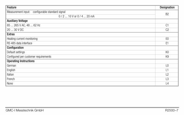
Measurement input: configurable standard signalB2
0 / 2 ... 10 V or 0 / 4 ... 20 mAAuxiliary Voltage85 ... 265 V AC, 48 ... 62 Hz C120 ... 30 V DC C2ExtrasHeating current monitoring E0RS 485 data interface E1ConfigurationDefault settings K0Configured per customer requirements K9Operating InstructionsGerman L0English L1Italian L2French L3None L4
Feature Designation

GMC-I Messtechnik GmbH R2500–8
Mechanical Installation / Preparation
Figure 1: Housing Dimensions and Panel Cutout
The R2500 controller is intended for installation to a control panel. The installation location should be vibration-free to the greatest possible extent. Aggressive vapors shorten the service life of the controller. Requirements set forth in VDE 0100 must be observed during the performance of all work. Work on the device may only be carried out by trained personnel who are familiar with the dangers involved.
Set the housing into the panel cutout from the front, and secure it from
behind at the top and bottom with the two included snap retainers. Several devices can be mounted next to each other without separators at the side.
In general, unobstructed air circulation must be assured when one or several devices are installed. The ambient temperature underneath the devices may not exceed 50 C. In order to assure IP 67 protection, an appropriate seal must be installed between the device and the panel.
Electrical Connection
Figure 2: Connector Terminal Positions
48
48
45+0.6
45+0.6
104119
5
12121415151617181920
123456789
10
Connectors: screw terminals for wire with 1.5 square mm cross-section or two-core wire-end ferrules for 2 0.75 square mm

GMC-I Messtechnik GmbH R2500–9
Attention: to ensure radio interference suppression, the protective conductor and/or control cabinet grounding must be connected to terminal 13.
Binary Input Transistor Output Cont.Output
Auxiliary Voltage
A1, A2, A5 A5 C1 C2
1 1 11
2 – – 2 – 12
3 + out1 3 + 13
4 + out2 + out2 4 14
5 5 15
6 6 16
7 7 17
8 A 8 18
9 B 9 19
10 C 10 20
B1 B2 E0 E1Relay
Outputs
A2, A5
SensorHeating Current
TransformerRS 485 Relay
Output
110 / 230 V ACN
L24 V DC–
+
20 mA / 10 V
20 mA
10 V
out 1
A1
A2

GMC-I Messtechnik GmbH R2500–10
Operation
Setting Values with the Up and Down Scroll Keys– At the operating level, the setpoint can be adjusted within a range extending from the minimum to the maximum setpoint.– Configuration and parameter settings can be changed if password protection has not been activated, or if the correct password has been entered.– In order to avoid erroneous settings, changes must be acknowledged within 5 seconds with the key.– The change can be discarded by pressing the key.
Actual value
Setpoint / heating current / Switching output for heating activeSwitching output for cooling active
Alarm 1 active
Select: Off/manual automatic operation
Setpoint 2 active
Manual operation
Reduce value / increase value
Switch displays, levels and values(see operating flow chart)
Figure 3: Controls
Alarm 2 activeInfrared interface (see page 50)
manipulating factor (operating level)

GMC-I Messtechnik GmbH R2500–11
Disabling ModificationsThe default setting (PSEt = dEF) allows for modification of all parameters and configurations. The following settings can be used in order to disable the entry of changes:Disabling Setpoint ChangesThe setpoint can only be adjusted between its minimum and maximum values. The SPL and SPH parameters must be set accordingly.Disabling Changes to Parameters and ConfigurationsAfter password protection for device operation has been activated (PASS not equal to diS), changes can only be made after the correct password has been entered. However, changes are always possible via infrared or bus interface!Disabling Self-TuningStarting self-tuning by pressing the corresponding keys can be separately disabled with the configuration tunE = diS.However, self-tuning can always be started via infrared or bus interface!
Performance After Activating Auxiliary Voltage
Actual Value
Setpoint or oFF
U/M
Firmware Version
LED Segment Test
Approx. 1.5 s Approx. 1.5 sApprox. 1.5 s
Designations

GMC-I Messtechnik GmbH R2500–12
Operating Flow Chart
Actual
Ht. Current Man. Factor
Automatic Operation
Actual
Setpoint
Actual Actual
Param. Value
Param. Value
Operating Level
Press key briefly. Press and hold key until display switches.
(page 27) (page 14)
With heat currentmonitoring only
Setpoint can only beset here
Configuration
Configuration
ConfigureParameter Level
* *
*) If password protection for device operation is activated (configuration: PASS = EnA ), the correct password must be entered in order to change values. Otherwise -no- appears at the display if an attempt is made to change a value.
Actual
With programcontroller only
Program
Program
Program Controller
*
Press and hold both keys until display switches.
GMC-I Messtechnik GmbH R2500–13
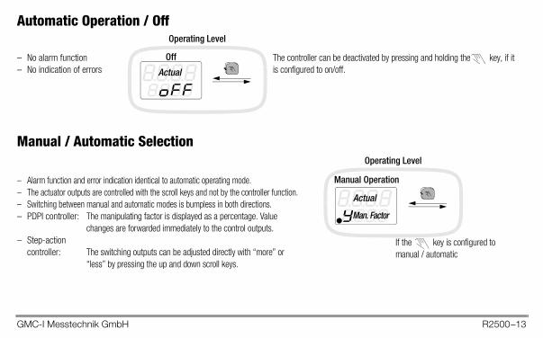
Automatic Operation / Off
Manual / Automatic Selection
Actual
Off– No alarm function– No indication of errors
Operating Level
The controller can be deactivated by pressing and holding the key, if it is configured to on/off.
Man. Factor
Actual
Manual Operation
Operating Level
– Alarm function and error indication identical to automatic operating mode.– The actuator outputs are controlled with the scroll keys and not by the controller function.– Switching between manual and automatic modes is bumpless in both directions.– PDPI controller: The manipulating factor is displayed as a percentage. Value
changes are forwarded immediately to the control outputs.– Step-action
controller: The switching outputs can be adjusted directly with “more” or “less” by pressing the up and down scroll keys.
If the key is configured to manual / automatic

GMC-I Messtechnik GmbH R2500–14
Configuration press and hold simultaneously
Configuration Display Selection Standard CommentSensor type
SEnS
tYP.j Types JtYP.L LtYP.K KtYP.b BtYP.S StYP.r RtYP.n NtYP.E EtYP.t TtYP.v UtYP.C CtYP.- –Pt 1 Pt100ni 1 Ni100ni12 Ni120rES –0HM Resistor in Lin Voltage in mV
Type JNot with standard signal
U/M SEnS 1° C, 1° F, 0.1° C, 0.1° F 1°CInput quantity SEnS 0 - 20 / 4 - 20 dead / live zero 0 - 20 With standard signal only
Controller type COut
MEAS Measure onlyP0W Actuator0n0F Limit transducerPdP1 2/3 step, step-action, split rangeProP Proportional actuator
PdPI See page 19
+
GMC-I Messtechnik GmbH R2500–15
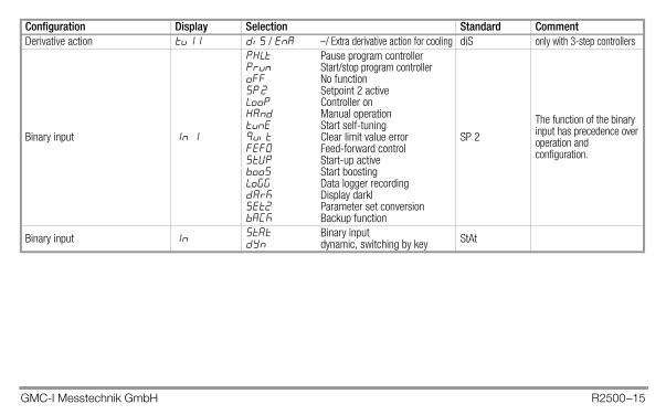
Derivative action tu 11 dis / ena –/ Extra derivative action for cooling diS only with 3-step controllers
Binary input 1n 1
phlt Pause program controllerprun Start/stop program controlleroFF No functionSP 2 Setpoint 2 activeLooP Controller onHAnd Manual operationtunE Start self-tuningQuit Clear limit value errorFEF0 Feed-forward controlStvP Start-up activebooS Start boostingLoGG Data logger recordingDark Display darklset2 Parameter set conversionbaCk Backup function
SP 2
The function of the binary input has precedence over operation and configuration.
Binary input 1n stat Binary inputdyn dynamic, switching by key StAt
Configuration Display Selection Standard Comment

GMC-I Messtechnik GmbH R2500–16
out1 switching output 0ut1
tr2 Controller 2tr1 Controller 1phlt Program pauseprun Program runningoFF No functionHEAt Heater, more heat
with step-action controllerCooL Cooling, more cooling
with step-action controllerH20 Water coolingHclo Less heat w. step-action controllerCclo Less cooling w. step-action controllerHotr Hot-runner heat1ndu Induction heatingal1l 1st lower limit value
HEAtSee page 21
out2 switching output 0ut 2 Same as out1 switching output oFF
Switching output selection 0utnor As configuredxCh Outputs out1 and out2
exchanged with A1 and A2nor See page 21
Continuous Output Cont
oFF No functionHEAt Heater,CooL Cooling,Proc Current controlled variableSP Current setpoint
oFF See pages 21 and 22,only if a continuous output is present (designation A5)
Continuous output Cont 0 - 20 / 4 - 20 Dead / live zero 20-0 / 20-4 dead / live zero invers 0 - 20
Alarm 1 A 1 noc / ncc Operating current / idle current noc See page 39Alarm 2 A 2 noc / ncc Operating current / idle current noc
Configuration Display Selection Standard Comment
GMC-I Messtechnik GmbH R2500–17
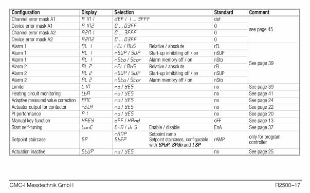
Channel error mask A1 A1M1 def / 1 ... 3FFF def
see page 45Device error mask A1 A1M2 0 ... 03FF 0Channel error mask A2 A2M1 0 ... 3FFF 0Device error mask A2 A2M2 0 ... 03FF 0Alarm 1 AL 1 rEL / AbS Relative / absolute rEL
See page 39
Alarm 1 AL 1 nSvP / SvP Start-up inhibiting off / on nSUPAlarm 1 AL 1 nSto / Stor Alarm memory off / on nStoAlarm 2 AL 2 rEL / AbS Relative / absolute rELAlarm 2 AL 2 nSvP / SvP Start-up inhibiting off / on nSUPAlarm 2 AL 2 nSto / Stor Alarm memory off / on nStoLimiter L1M no / yes no See page 39Heating circuit monitoring LbA no / yes no See page 41Adaptive measured value correction AMC no / yes no See page 24Actuator output for contactor rELA no / yes no See page 22PI performance p1 no / yes no See page 20Manual key function HKEY oFF / HAnd oFF See page 13Start self-tuning tune EnA / diS Enable / disable EnA See page 37
Setpoint staircase spramp Setpoint rampstep Setpoint staircases, configurable
with SPuP, SPdn and t SPrAMP only for program
controller
Actuation inactive Stvp no / yes no See page 25
Configuration Display Selection Standard Comment
GMC-I Messtechnik GmbH R2500–18
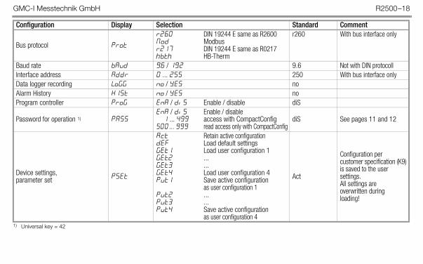
1) Universal key = 42
Bus protocol Prot
r260 DIN 19244 E same as R2600Mod Modbusr217 DIN 19244 E same as R0217hbth HB-Therm
r260 With bus interface only
Baud rate bAUd 9.6 / 19.2 9.6 Not with DIN protocollInterface address Addr 0 ... 255 250 With bus interface onlyData logger recording logg no / yes noAlarm History h1st no / yes noProgram controller prog EnA / diS Enable / disable diS
Password for operation 1) PASSEnA / diS Enable / disable
1 ... 499 access with CompactConfig500 ... 999 read access only with CompactConfig
diS See pages 11 and 12
Device settings, parameter set pset
Act Retain active configurationdEF Load default settingsGEt1 Load user configuration 1GEt2 ...GEt3 ...GEt4 Load user configuration 4Put1 Save active configuration
as user configuration 1 Put2 ...Put3 ...Put4 Save active configuration
as user configuration 4
Act
Configuration per customer specification (K9) is saved to the user settings.All settings are overwritten during loading!
Configuration Display Selection Standard Comment

GMC-I Messtechnik GmbH R2500–19
Controller Types
Controller Type ApplicationsMeasure (Cout = MEAS) This configuration is intended for temperature monitoring.
Limit value monitoring can be configured. System deviation is not used for any other purposes.Actuator (Cout = POW) Same as controller type 1 (measure)
In addition, the actuator manipulating factor is read out with the actuating cycle.Limit transducer (Cout = OnOF) The maximum manipulating factor is read out if the actual value is less than the momentary setpoint.
The minimum manipulating factor is read out if the actual value is greater than the momentary setpoint plus the dead zone.Switching hysteresis is adjustable, and status changes are possible after each actuating cycle.Actuating cycle time is used as a time constant for an additional input filter.
PDPI controller and PDPI step-action controller (Cout = PdPI )
The PDPI control algorithm assure short settling time without overshooting.The actuating cycle is at least as long as the selected value.The dead band inhibits switching back and forth between “heating” and “cooling” if no lasting deviation occurs.Selection of these two controller types, namely PDPI and PDPI step-action controller, defines the controller itself on the basis of the output configuration.
Proportional actuator (Cout = ProP)
The control variable is proportional to system deviation, and a statistical dead zone can be adjusted at the cooling side.Actuating cycle time is used as a time constant for an additional input filter.This controller type is not intended for temperature regulation, because it does not demonstrate the dynamics required for control without overshooting.
GMC-I Messtechnik GmbH R2500–20
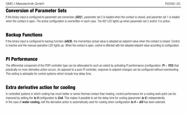
Conversion of Parameter SetsIf the binary input is configured to parameter set conversion (SEt2 ), parameter set 2 is loaded when the contact is closed, and paramter set 1 is loaded when the contact is open. The active configuration is overwritten in each case. The W2 LED lights up when parameter set 2 and/or 3 is active.
Backup FunctionsIf the binary input is configured to backup function (bACK), the momentary actual value is adopted as setpoint value when the contact is closed. Control is inactive and the manual operation LED lights up. When the contact is open, control is effected with the adopted setpoint value according to configuration.
PI PerformanceThe differential component of the PDPI controller type can be attenuated to such an extent by activating PI performance (configuration: PI = YES) that practically no more derivative action occurs. As opposed to a pure PI controller, response to setpoint changes can be configured without overshooting. This setting is advisable for control systems which include true delay time.
Extra derivative action for coolingIn controlled systems in which cooling has much better or worse thermal contact than heating, control performance for a cooling work point can be improved by setting the tu II configuration to EnA. This makes it possible to set the delay time for cooling (parameter tu II ) independently.In the case of water cooling, half the derivative action is automatically used for cooling when configuration tu II = diS has been selected.

GMC-I Messtechnik GmbH R2500–21
Configuring the Switching Outputs and the Continuous OutputSwitching output out1 is configured with a 2-step heating controller as a standard feature (relay or transistor output, depending upon variant).Control performance (2-step heating or cooling, 3-point discontinuous, step-action controller, continuous-action controller, split range controller) is determined by the configuration selected for the actuating outputs. See also the “Configuration” table on page 16.– Actuators for heating and cooling are selected independent of each other.– If 2-step control is required, heating and cooling outputs may not be configured simultaneously for the respective controller.– Both switching outputs can be assigned to the same controller output for separate control of several actuators with a single controller output.– If a continuous and a discontinuous output are both configured for heating (or cooling) at the same time, the channel performs like a
continuous-action controller and the discontinuous output is inactive.– If, inadvertently, only one “Less” output is configured for heating (or cooling), it remains inactive. – Settings can be freely combined regardless of controller type.
Relay Outputs for Actuating SignalsIf two relay outputs are required for the actuating signals, for example in the case of three-step or step-action control, the alarm outputs can be exchanged with the actuator outputs.The Out = XCh configuration (see page 16) exchanges the functions of out1 with A1 and out2 with A2.
GMC-I Messtechnik GmbH R2500–22
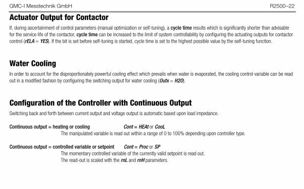
Actuator Output for ContactorIf, during ascertainment of control parameters (manual optimization or self-tuning), a cycle time results which is significantly shorter than advisable for the service life of the contactor, cycle time can be increased to the limit of system controllability by configuring the actuating outputs for contactor control (rELA = YES). If the bit is set before self-tuning is started, cycle time is set to the highest possible value by the self-tuning function.
Water CoolingIn order to account for the disproportionately powerful cooling effect which prevails when water is evaporated, the cooling control variable can be read out in a modified fashion by configuring the switching output for water cooling (Outx = H2O).
Configuration of the Controller with Continuous OutputSwitching back and forth between current output and voltage output is automatic based upon load impedance.
Continuous output = heating or cooling Cont = HEAt or CooLThe manipulated variable is read out within a range of 0 to 100% depending upon controller type.
Continuous output = controlled variable or setpoint Cont = Proc or SPThe momentary controlled variable of the currently valid setpoint is read out. The read-out is scaled with the rnL and rnH parameters.
GMC-I Messtechnik GmbH R2500–23
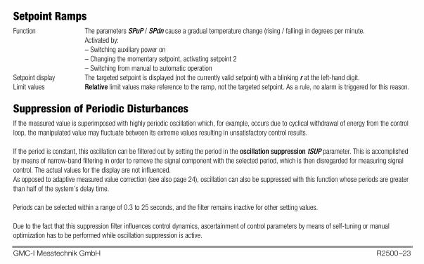
Setpoint RampsFunction The parameters SPuP / SPdn cause a gradual temperature change (rising / falling) in degrees per minute.
Activated by:– Switching auxiliary power on– Changing the momentary setpoint, activating setpoint 2– Switching from manual to automatic operation
Setpoint display The targeted setpoint is displayed (not the currently valid setpoint) with a blinking r at the left-hand digit.Limit values Relative limit values make reference to the ramp, not the targeted setpoint. As a rule, no alarm is triggered for this reason.
Suppression of Periodic DisturbancesIf the measured value is superimposed with highly periodic oscillation which, for example, occurs due to cyclical withdrawal of energy from the control loop, the manipulated value may fluctuate between its extreme values resulting in unsatisfactory control results.
If the period is constant, this oscillation can be filtered out by setting the period in the oscillation suppression tSUP parameter. This is accomplished by means of narrow-band filtering in order to remove the signal component with the selected period, which is then disregarded for measuring signal control. The actual values for the display are not influenced.As opposed to adaptive measured value correction (see also page 24), oscillation can also be suppressed with this function whose periods are greater than half of the system’s delay time.
Periods can be selected within a range of 0.3 to 25 seconds, and the filter remains inactive for other setting values.
Due to the fact that this suppression filter influences control dynamics, ascertainment of control parameters by means of self-tuning or manual optimization has to be performed while oscillation suppression is active.

GMC-I Messtechnik GmbH R2500–24
Adaptive Measured Value CorrectionIf a control loop is interfered with by periodic disturbance of the actual value, control can be improved by activating adaptive measured value correction. Periodic disturbance is thus suppressed, without impairing the controller’s ability to react to system deviations. Correction is adapted to the oscillation amplitude of the disturbance to this end, and only the mean value is forwarded to the controller.
Adaptation of correction to the disturbance is matched to prevailing control dynamics and requires no further parameters.
Prerequisites for improved control:– The oscillation amplitude of the disturbance must be constant, or may only change slowly.– The oscillation period must be less that half of the system’s delay time (parameter tu).
Due to the fact that correction greatly influences actual value ascertainment, control may also be worsened, for example if:– Measured value deviations are irregular– Individual measured value outliers occur– Fluctuation is not periodic– The disturbance is noise-like

GMC-I Messtechnik GmbH R2500–25
Hot-Runner ControlBy configuring the switching output for heating as a hot runner (Outx = Hotr), the manipulated variable is read out as a rapidly pulsating signal, i.e. actuation cycle time is 0.1 seconds regardless of the actuation cycle time parameter setting.With the help of this configuration, the start-up circuit and boost functions are also enabled.
Start-Up CircuitThe start-up circuit is enabled with the StUP = YES configuration, or by means of the binary input when it has been configured as follows: In1 = StUP.The start-up circuit is only enabled for controller type PDPI. No start-up occurs for other controller types.The start-up procedure is initiated if the actual value is more than 2 °C less than the start-up setpoint after auxiliary voltage is turned on (reset)
or after the off state has been ended,or if the actual value drops to more than 40 °C less than the start-up setpoint after a start-up procedure has been completed or during dwell time.
Start-up continues until the actual value exceeds the start-up value minus 2 °C.The control variable is limited to the start-up manipulating factor.
Dwell time then begins, which is selected with the dwell time parameter.The controller regulates temperature to the actuation setpoint.
The actuation procedure is ended as soon as dwell time has expired.The controller then regulates temperature to the valid setpoint.
If the currently valid setpoint is still so far beneath the start-up setpoint that the condition for ending actuation cannot be fulfilled, the start-up procedure continues indefinitely. In this case, control variable limiting by means of maximum manipulating factor would be advisable.
GMC-I Messtechnik GmbH R2500–26
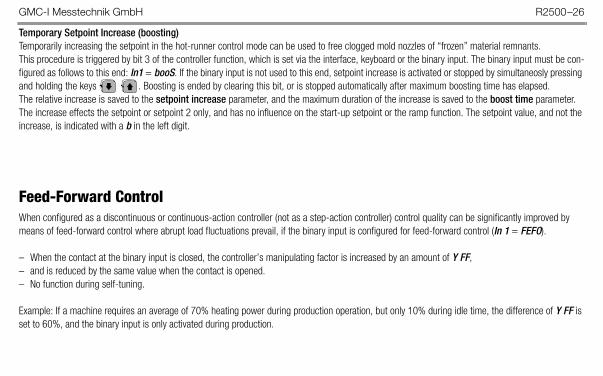
Temporary Setpoint Increase (boosting)Temporarily increasing the setpoint in the hot-runner control mode can be used to free clogged mold nozzles of “frozen” material remnants. This procedure is triggered by bit 3 of the controller function, which is set via the interface, keyboard or the binary input. The binary input must be con-figured as follows to this end: In1 = booS. If the binary input is not used to this end, setpoint increase is activated or stopped by simultaneosly pressing and holding the keys . Boosting is ended by clearing this bit, or is stopped automatically after maximum boosting time has elapsed.The relative increase is saved to the setpoint increase parameter, and the maximum duration of the increase is saved to the boost time parameter.The increase effects the setpoint or setpoint 2 only, and has no influence on the start-up setpoint or the ramp function. The setpoint value, and not the increase, is indicated with a b in the left digit.
Feed-Forward ControlWhen configured as a discontinuous or continuous-action controller (not as a step-action controller) control quality can be significantly improved by means of feed-forward control where abrupt load fluctuations prevail, if the binary input is configured for feed-forward control (In 1 = FEFO).
– When the contact at the binary input is closed, the controller’s manipulating factor is increased by an amount of Y FF,– and is reduced by the same value when the contact is opened.– No function during self-tuning.
Example: If a machine requires an average of 70% heating power during production operation, but only 10% during idle time, the difference of Y FF is set to 60%, and the binary input is only activated during production.

GMC-I Messtechnik GmbH R2500–27
Parameters Configuration Press and hold X1 = lower range limit, X2 = upper rang limit, MRS = X2 – X1
Parameters Display Range Standard CommentsUpper limit value for relay A1 al1h
oFF, 1 ... MRS/2 oFF, X1 ... X2
oFFoFF
Relative (= default config.)Absolute
Lower limit value for relay A1 al1lUpper limit value for relay A2 al2hLower limit value for relay A2 al2lSetpoint 2 sp 2 SP L ... SP H X1Ramp for rising setpoints spup oFF, 1 ... MRS/2 per min. oFF
See page 23Ramp for falling setpoints spdn oFF, 1 ... MRS/2 per min. oFFHeating current setpoint (see balancing) amps Auto, oFF, 0.1 ... A H oFF Not with step-action controller or bus interface
Proportional band heating pb 1 0 ... MRS/2 50Proportional band cooling pb11 0 ... MRS/2 50 Only with 3-step controllersDead band H/C dbnd 0 ... MRS/2 0 Not with 2-step controllersPath delay time tu 0 ... 900 s 50 s
Cooling path delay time tu11 0 ... 900 s 50 s Only with 3-step controllers if extra derivative action has been configured
Read-out cycle time tc 0.1 ... 300 s 1 sMotor run-time ty 1 ... 600 s 60 s Only with step-action controllersSwitching hysteresis hyst 0 ... MRS/2 4 For limit value monitoring and limit transducers

GMC-I Messtechnik GmbH R2500–28
Maximum setpoint sp H SP L ... X2 X2Limiting the setpoint entry
Minimum setpoint SP L X1 ... SP H X1Maximum manipulating factor y H –100 ... 100% 100%Minimum manipulating factor y l –100 ... 100% –100%Actual value correction Cal –MRS/2 ... +MRS/2 0
Not with standard signalActual gain value gain 0 ... 500% 100%Decimal point position dpnt 0, 0.1, 0.02, 0.003 0
With standard signal onlyUpper range limit, standard signal rn h r n L ... 9999 100Lower range limit, standard signal rn l –1999 ... r n H 0Manip. factor for actuation mode y st –100 ... 100% 0Manip. factor for feed-forward control y ff –100 ... 100% 0 See page 26Sensor error manipulating factor y se –100 ... 100% 0 See page 43Actuation setpoint spsv SP L ... SP H 0
For hot-runner controllers only, see pages 25 and 26
Start-up manipulating factor y sv –100 ... 100% 10Dwell time t sv 0 ... 300 s 0Boosting (setpoint increase) spbo 0 ... MRS/2 0Boosting time t bo 0 ... 600 s 0Oscillation inhibiting tsvp oFF, 0.3 ... 25 s oFF See page 23
Parameters Display Range Standard Comments

GMC-I Messtechnik GmbH R2500–29
Program ControllerActivation At the configuration level with ProG = EnA
Function The current setpoint is determined exclusively by the program.Eight programs with twelve segments each are saved to the controller and can be selected.The functions which otherwise influence the setpoint, such as setpoint swapping and setpoint ramps, as well as the start-up circuit and boosting for hot-runner control, are without function.
Program Each of the twelve program segments is defined by means of segment duration, targeted setpoint and the control tracks,and the program can be set to end upon completion of the first through the eleventh segment as well.
Sequence StoP The program has been completed or stopped, or hasn’t yet been started (after a reset).The controller and the actuator outputs are inactive, relative limit value errors are suppressed.The momentary setpoint is set to the actual value.The program is started over again after it has been stopped.
run.X The program has been started, possibly automatically after a reset (X stands for the current segment).The controller and the actuator outputs are active, relative limit value errors are enabled.Segment 1 is always executed when the program is started, and the initial setpoint is the actual value.The program can be started and stopped with a binary input: In1 = Prun.
Wt.X Same as for run.X. If “wait until setpoint is reached” has been selected (with WAit = YES), the program waits until system deviation amounts to only 2° C before activating the next segment.

GMC-I Messtechnik GmbH R2500–30
hLt.X The running program has been halted, the momentary setpoint has been frozen (X stands for the current segment).The program can be halted with a binary input: In1 = PhLt.
Control tracks Two control tracks can be activated for the duration of the segments. They can be assigned to available switching outputs with the setting: Out... = tr...The states run and hLt can also be assigned to available switching outputs with the settings: Out... = Prun and Out... = PhLt.
Control parameters When the program controller is active, the control parameters should not (cannot) be set manually or by means ofself-tuning, because a constant setpoint is required for usable optimization results.Select ProG = diS to this end.
Display The displays are supplemented as follows at the operating level:The momentary setpoint appears at the setpoint display when a program is running, and only dashes appear after the program has been ended because there is no longer an active setpoint. The setpoint cannot be changed.A status display also appears. Current status, namely StoP, run.X, Wt.X or hLt.X (X stands for the current segment), appears at the bottom display.
Operation The sequence can be controlled in the status display with the help of the up and down scroll keys, if it has not been configured to binary inputs. In order to avoid erroneous settings, changes must be acknowledged within 5 seconds with the key.The change can be discarded by pressing the key.
GMC-I Messtechnik GmbH R2500–31
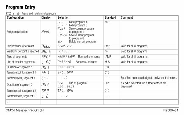
Program Entry Press and hold simultaneously
Configuration Display Selection Standard Comment
Program selection ProG
no. 1 Load program 1... no. 8 Load program 8Put1 Save current program
to program 1...Put8 Save current program
to program 8cLr Delete current program
no. 1
Performance after reset Auto StoP / run StoP Valid for all 8 programs
Wait Until Setpoint is reached wait no / yes no Valid for all 8 programs
Type of segments segs ramp / step Ramps/increments rAMP Valid for all 8 programs
Unit of time for segments tIME M-S / H-M Seconds / minutes M-S Valid for all 8 programs
Duration of segment 1 MS 1 0:00 ... 99:59 0:00
Target setpoint, segment 1 SP 1 SP L ... SPH 0°C
Control tracks, segment 1 tr 1 ---- ... 21 ---- Specified numbers designate active control tracks.
Duration of segment 2 MS 2 End End of program0:00 ... 99:59
End If End is selected, no further entries are displayed.
Target setpoint, segment 2 SP 2 SP L ... SP H 0°C
Control tracks, segment 2 tr 2 ---- ... 21 ----
...
+
GMC-I Messtechnik GmbH R2500–32
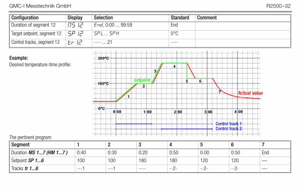
Example: Desired temperature-time profile:
The pertinent program:
Duration of segment 12 MS12 End, 0:00 ... 99:59 End
Target setpoint, segment 12 SP12 SP L ... SP H 0°C
Control tracks, segment 12 tr12 ---- ... 21 ----
Segment 1 2 3 4 5 6 7Duration MS 1...7 (HM 1...7 ) 0:40 0:30 0:20 0:50 0.00 0:50 End
Setpoint SP 1...6 100 100 180 180 120 120 —
Tracks tr 1...6 ---1 ---1 ---- --2- --2- --2- —
Configuration Display Selection Standard Comment
setpoint
Actual value
Control track 1Control track 2
GMC-I Messtechnik GmbH R2500–33
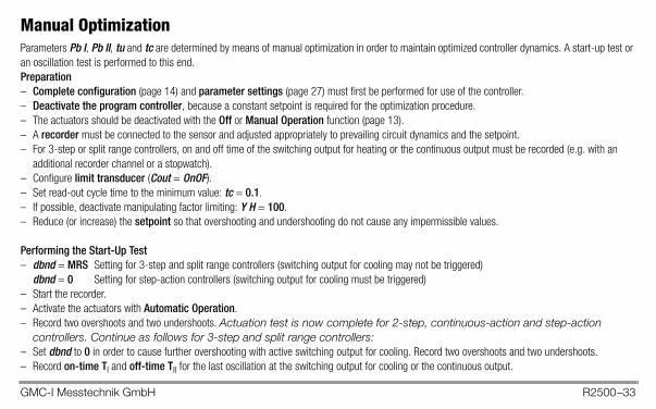
Manual OptimizationParameters Pb I, Pb II, tu and tc are determined by means of manual optimization in order to maintain optimized controller dynamics. A start-up test or an oscillation test is performed to this end.Preparation– Complete configuration (page 14) and parameter settings (page 27) must first be performed for use of the controller.– Deactivate the program controller, because a constant setpoint is required for the optimization procedure.– The actuators should be deactivated with the Off or Manual Operation function (page 13).– A recorder must be connected to the sensor and adjusted appropriately to prevailing circuit dynamics and the setpoint.– For 3-step or split range controllers, on and off time of the switching output for heating or the continuous output must be recorded (e.g. with an
additional recorder channel or a stopwatch).– Configure limit transducer (Cout = OnOF).– Set read-out cycle time to the minimum value: tc = 0.1.– If possible, deactivate manipulating factor limiting: Y H = 100.– Reduce (or increase) the setpoint so that overshooting and undershooting do not cause any impermissible values.
Performing the Start-Up Test– dbnd = MRS Setting for 3-step and split range controllers (switching output for cooling may not be triggered)
dbnd = 0 Setting for step-action controllers (switching output for cooling must be triggered)– Start the recorder.– Activate the actuators with Automatic Operation.– Record two overshoots and two undershoots. Actuation test is now complete for 2-step, continuous-action and step-action
controllers. Continue as follows for 3-step and split range controllers:– Set dbnd to 0 in order to cause further overshooting with active switching output for cooling. Record two overshoots and two undershoots.– Record on-time TI and off-time TII for the last oscillation at the switching output for cooling or the continuous output.

GMC-I Messtechnik GmbH R2500–34
Evaluating the Start-Up Test– Apply a tangent to the curve at the intersection of the actual value and the setpoint, or the cut-off point of the output.– Measure time t.– Measure oscillation amplitude xss, or for step-action controllers overshooting x.
If manipulating factor limiting was active, the proportional band must be corrected:Y H positive: Pb I multiply by 100% / Y HY H negative: Pb II multiply by -100% / Y H
Parameter Valuetu 1.5 t t – (tY / 4)tc tu / 12 tY / 100Pb I xss 2 xss x / 2Pb II – Pb I (TI / TII) – Pb I (TI / TII) –Parameter 2-step controller 3-step controller Cont.-action controller Split range controller Step-action controller
P
t
xxss
TI TII
dbnd = 0dbnd = MRS (3-step and split range controllers only)

GMC-I Messtechnik GmbH R2500–35
Performing the Oscillation TestIf a start-up test is not possible, for example if neighboring control loops influence the actual value too greatly, if the switching output for cooling must be active in order to maintain the actual value (cooling operating point), or if optimization is required directly to the setpoint for any given reason, control parame-ters can be determined by means of sustained oscillation. However, calculated values for tu may be very inaccurate in this case under certain circumstances.– Preparation as above. Test can be performed without a recorder if actual value is observed at the display, and if times are measured with a stopwatch.– dbnd = 0 Setting for 3-step, split range and step-action controllers– Activate the actuators with Automatic Operation, and if applicable start the recorder. Record several oscillations until they become uniform in size.– Measure oscillation amplitude xss.– Record on-time TI and off-time TII for the oscillations at the switching output for heating or the continuous output.
Evaluating the Oscillation Test
1 If either TI or TII is significantly greater than the other, value tu is too large.
Parameter Valuetu 1 0.3 (TI + TII) 0.2 (TI + TII – 2tY)tc tu / 12 tY / 100Pb I xss xss TII
(TI + TII)2 xss 2 xss TII
(TI + TII)xss / 2
Pb II – Pb I (TI / TII) – Pb I (TI / TII) –Parameters 2-step controller 3-step controller Cont.-action controller Split range controller Step-action controller
TI TIIxss
GMC-I Messtechnik GmbH R2500–36
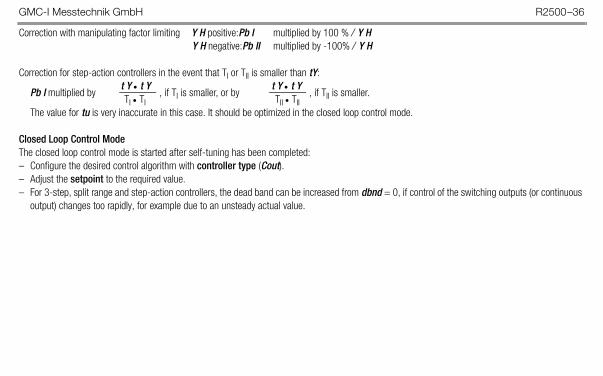
Correction with manipulating factor limiting Y H positive:Pb I multiplied by 100 % / Y HY H negative:Pb II multiplied by -100% / Y H
Correction for step-action controllers in the event that TI or TII is smaller than tY:t Y t Y t Y t Y
Pb I multiplied by , if TI is smaller, or by , if TII is smaller.TI TI TII TII
The value for tu is very inaccurate in this case. It should be optimized in the closed loop control mode.
Closed Loop Control ModeThe closed loop control mode is started after self-tuning has been completed:– Configure the desired control algorithm with controller type (Cout).– Adjust the setpoint to the required value.– For 3-step, split range and step-action controllers, the dead band can be increased from dbnd = 0, if control of the switching outputs (or continuous
output) changes too rapidly, for example due to an unsteady actual value.
GMC-I Messtechnik GmbH R2500–37
Self-Tuning
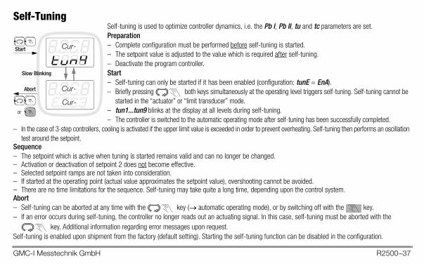
Sequence– The setpoint which is active when tuning is started remains valid and can no longer be changed.– Activation or deactivation of setpoint 2 does not become effective.– Selected setpoint ramps are not taken into consideration.– If started at the operating point (actual value approximates the setpoint value), overshooting cannot be avoided.– There are no time limitations for the sequence. Self-tuning may take quite a long time, depending upon the control system.Abort– Self-tuning can be aborted at any time with the key ( automatic operating mode), or by switching off with the key.– If an error occurs during self-tuning, the controller no longer reads out an actuating signal. In this case, self-tuning must be aborted with the
key. Additional information regarding error messages upon request.Self-tuning is enabled upon shipment from the factory (default setting). Starting the self-tuning function can be disabled in the configuration.
Self-tuning is used to optimize controller dynamics, i.e. the Pb I, Pb II, tu and tc parameters are set.Preparation– Complete configuration must be performed before self-tuning is started.– The setpoint value is adjusted to the value which is required after self-tuning.– Deactivate the program controller.Start– Self-tuning can only be started if it has been enabled (configuration: tunE = EnA).– Briefly pressing both keys simultaneously at the operating level triggers self-tuning. Self-tuning cannot be
started in the “actuator” or “limit transducer” mode.– tun1...tun9 blinks at the display at all levels during self-tuning.– The controller is switched to the automatic operating mode after self-tuning has been successfully completed.
– In the case of 3-step controllers, cooling is activated if the upper limit value is exceeded in order to prevent overheating. Self-tuning then performs an oscillation test around the setpoint.
Cur-
Cur-
Cur-
Start
Abort
Slow Blinking
or

GMC-I Messtechnik GmbH R2500–38
BalancingThermocouple Correction (parameter: CAL)The correction value is selected in C / F. The displayed correction value is added to the measured temperature.
Cable Compensation for Pt 100 with 2-Wire Connection (parameter: CAL)Balancing is performed manually if the sensor temperature is known: CAL = known sensor temperature – displayed temperature value
Correction of a Temperature Gradient (parameter: GAin)If the measured temperature value is not to be displayed, but rather a value which deviates from it, the GAin parameter is set to a value other than 100%:
temperature to be displayed in C 100%GAin =
measured temperature in C
Scaling for Heating Current Monitoring (parameter: A H)The default setting for the GTZ 4121 is 42.7 A. If the GTZ 4121 current transformer is not used for acquiring heating current, the current value must be selected at which the utilized transformer generates an output voltage of 10 V DC.
Ascertaining the Nominal Heating Current Value (parameter: AMPS)By setting AMPS = Auto, control is interrupted for about 1 second, heating is activated and heating current is measured and saved as the nominal value. If the value is not equal to zero, heating current monitoring is automatically activated.

GMC-I Messtechnik GmbH R2500–39
Limit Value Monitoring
Start-up inhibiting: Alarm suppression is active during start-up (configuration: ALx = SUP) until temperature has exceeded the lower limit level for the first time. During cooling, suppression is active until temperature has fallen below the upper limit value for the first time. It is active when auxiliary power is activated, if the current setpoint is changed or setpoint 2 is activated, or if switching takes place from Off toAutomatic Operation.
LimiterIf a controller needs to be deactivated in the event of a limit value violation within the control loop, the controller must be configured as a limiter (LIM = YES). The limiter can be combined with all controller types.– The limiter responds to the second limit value, which must be set and configured accordingly.– The controller is deactivated as soon as a second limit value is violated. The controller becomes active again when there are no more limit value errors.– If the controller is to remain continuously deactivated after limit value monitoring has been triggered, the alarm memory must be activated
(configuration: AL2 = Stor).– The limit value errors must then be cleared in order to reactivate the controller. This is accomplished by pressing the key and acknowledging
the Quit AL display within 5 seconds with the key.– These errors can also be cleared with the binary input, if it has been configured to clear limit value errors (In 1 = quit).
Alarm Relay, NO ContactAlarm Relay, NC Contact
AL L AL H Relative Limit ValuesAL L AL H Absolute Limit Values
Actual VSetpoint
Hysteresis adjustable with HYSt parameter
GMC-I Messtechnik GmbH R2500–40
Heating Current MonitoringCurrent Measurement Heating current is acquired with an external transformer. Compatible with R2400 with GTZ 4121 for alternating and 3-phase
current. Function An alarm is triggered if the current setpoint is fallen short of by more than 20% with activated heat (control output active), or
if current is not “off” when the heat is switched off. The alarm is not triggered until heating current is high enough when the switching output for heating is active, and when current drops to zero when the switching output for heating is inactive. Monitoring is only active if discontinuous heating has been selected in the configuration, and not in the case of continuous and step-action controllers.
Threshold The default monitoring threshold is 20%. AMPS current setpoint Heater phase current is entered for this parameter. AMPS can be set to Auto for automatic adjustment with the heater
switched on. The measured current value is saved to memory.Activation Parameter AMPS not set to oFF.

GMC-I Messtechnik GmbH R2500–41
Heating Circuit Monitoring– Function – Can be set to active or inactive with the LbA configuration
– Without external transformer, without additional parameters– Assumes correct optimization of tu and Pb I control parameters!
Due to the fact that self-tuning generates other results in certain cases when heating circuit monitoring is activated, heating circuit monitoring must be activated before self-tuning is started.
– In the event of manual optimization or subsequent adaptation of control parameters, the lower limit for the tu parameter must be observed:
2·Pb IMinimum tu =
t t = maximum temperature rise during start-up
– Error message LE appears after approximately 2 times tu, if heat remains on at 100% and measured temperature rise is too small.
– Monitoring is not active:Where controller type = limit transducer, actuator or step-action controllerDuring self-tuningWith standard signal input (designation B2)Where manipulating factor limiting Y H < 20%

GMC-I Messtechnik GmbH R2500–42
Alarm History• The alarm history includes 100 error status entries with the respective time stamps. Whenever at least one entire bit of the overall error status
changes, the complete error status is saved with the current time stamp.• Recording is started over each time the device is reset, and data are lost if auxiliary power fails. Recording can be activated with the setting
HISt = YES in the configuration, or via interfaces.• After the ring buffer has been filled to capacity with 100 entries, the oldest entry is deleted each time a new one is recorded.• Entries can only be read out via the bus interface or the infrared interface. See the interface description for detailed information.
Data Logger• The data logger has enough capacity for 3600 sampled value pairs including actual values and manipulated variables. The logger sampling cycle
can be configured within a range of 0.1 to 300.0 seconds. This results in recording times of 0.1 to 300 hours (6 minutes to 12 days).• Recording must be started over again each time the device is reset, and data are lost if auxiliary power fails.• Recording can be started via a binary input, with the setting LoGG = YES in the configuration or via interface.• After the ring buffer has been filled to capacity with 3600 entries, the oldest values are deleted as new ones are recorded.• Entries can only be read out via the bus interface or the infrared interface. See the interface description for detailed information.
GMC-I Messtechnik GmbH R2500–43
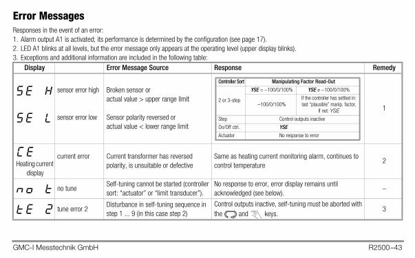
Error MessagesResponses in the event of an error:1. Alarm output A1 is activated; its performance is determined by the configuration (see page 17).2. LED A1 blinks at all levels, but the error message only appears at the operating level (upper display blinks).3. Exceptions and additional information are included in the following table:
Display Error Message Source Response Remedy
sensor error high
sensor error low
Broken sensor oractual value > upper range limit
Sensor polarity reversed oractual value < lower range limit
1
Heating current display
current error Current transformer has reversed polarity, is unsuitable or defective
Same as heating current monitoring alarm, continues to control temperature
2
no tuneSelf-tuning cannot be started (controller sort: “actuator” or “limit transducer”).
No response to error, error display remains until acknowledged (see below).
–
tune error 2Disturbance in self-tuning sequence in step 1 ... 9 (in this case step 2)
Control outputs inactive, self-tuning must be aborted with the and keys.
3
Controller Sort Manipulating Factor Read-Out
2 or 3-step
YSE = –100/0/100% YSE –100/0/100%
–100/0/100%If the controller has settled in:last “plausible” manip. factor,
If not: YSEStep Control outputs inactive
On/Off ctrl. YSEActuator No response to error

GMC-I Messtechnik GmbH R2500–44
Remedies
Error AcknowledgementErrors are acknowledged by pressing the key and acknowledging the Quit AL display within 5 seconds with the key.
loop errorMeasured temperature rise is too small with heat on at 100%
Control outputs inactive, error message remains until acknowledged (see below).
4
parameter error Parameter not within permissible limits Control outputs inactive, the parameter level is disabled. 5
digital errorError detected by digital component monitoring
Control outputs inactive 6
analog errorHardware error detected by analog component monitoring
Control outputs inactive 6
Display Error Message Source Response Remedy
1. Eliminate sensor error.2. Inspect current transformer.3. Avoid disturbances which impair the self-tuning sequence, e.g. sensor
errors.4. Close the control loop: Check the sensor, the actuators and the heater for
correct functioning. Check sensor-heater assignments (wiring). Correctly optimize control parameters tu and Pb I.
5. Restore default configuration and default parameters, and then reconfigure or load user-defined default settings.
6. Arrange for repair at authorized service center.
GMC-I Messtechnik GmbH R2500–45
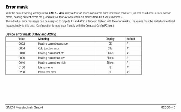
Error maskWith the default setting (configuration A1M1 = def), relay output A1 reads out alarms from limit value monitor 1, as well as all other errors (sensor errors, heating current errors etc.), and relay output A2 only reads out alarms from limit value monitor 2.The individual error messages can be assigned to outputs A1 and A2 in a targeted fashion with the error masks. The values must be added and entered hexadecimally to this end. (Configuration is more user friendly with the Compact Config PC tool.)
Device error mask (A1M2 and A2M2)Value Meaning Display default0002 Heating current overrange CE A1
0004 Cold junction error CJE A1
0010 Heating current not off Blinks A1
0020 Heating current too low Blinks A1
0040 Heating current too high Blinks A1
0100 Memory error FE A1
0200 Parameter error PE A1
GMC-I Messtechnik GmbH R2500–46
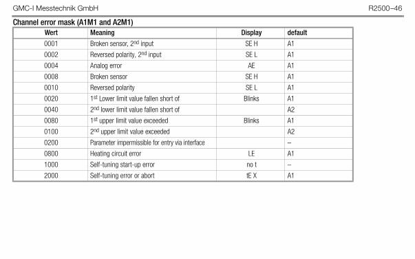
Channel error mask (A1M1 and A2M1)Wert Meaning Display default0001 Broken sensor, 2nd input SE H A1
0002 Reversed polarity, 2nd input SE L A1
0004 Analog error AE A1
0008 Broken sensor SE H A1
0010 Reversed polarity SE L A1
0020 1st Lower limit value fallen short of Blinks A1
0040 2nd lower limit value fallen short of A2
0080 1st upper limit value exceeded Blinks A1
0100 2nd upper limit value exceeded A2
0200 Parameter impermissible for entry via interface –
0800 Heating circuit error LE A1
1000 Self-tuning start-up error no t –
2000 Self-tuning error or abort tE X A1
GMC-I Messtechnik GmbH R2500–47
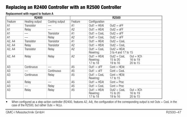
Replacing an R2400 Controller with an R2500 ControllerReplacement with regard to feature A
• When configured as a step-action controller (R2400, features A2, A4), the configuration of the corresponding output is not Outx = CooL in the case of the R2500, but rather Outx = HcLo.
R2400 R2500Feature Heating output Cooling output Feature ConfigurationA1 Transistor — A1 Out1 = HEAt Out2 = oFFA1 Relay — A2 Out1 = HEAt Out2 = oFFA1 — Transistor A1 Out1 = CooL Out2 = oFFA1 — Relay A2 Out1 = CooL Out2 = oFFA2, A4 Transistor Transistor A1 Out1 = HEAt Out2 = CooLA2, A4 Relay Transistor A2 Out1 = HEAt Out2 = CooLA2, A4 Transistor Relay A2 Out1 = CooL Out2 = HEAt
Rewiring: 3 to 4 and 17 to 15A2, A4 Relay Relay A2 Out1 = HEAt Out2 = CooL Out = XCh
Rewiring: 15 to 20 16 to 19 17 to 18 19 to 16 20 to 15
A3 Continuous — A5 Out1 = oFF Cont = HEAtA3 — Continuous A5 Out1 = oFF Cont = CooLA3 Continuous Relay A5 Out1 = CooL Cont = HEAt
Rewiring: 17 to 15A3 Relay — A5 Out1 = HEAt Cont = ProcA3 — Relay A5 Out1 = CooL Cont = ProcA3 Relay Relay A5 Out1 = HEAt Out2 = CooL Out = XCh
Rewiring: 15 to 20 16 to 19 17 to 18 19 to 16 20 to 15
GMC-I Messtechnik GmbH R2500–48
Replacement with regard to features B and C:• Features B1 and B2 are identical for both devices.• Features C1 and C2 for the R2400 are feature C1 for the R2500.• Feature C3 cannot be replaced with the R2400.• Feature C4 for the R2400 is feature C2 for the R2500.
The following functions cannot be replaced:• Position acknowledgement display for step-action controller (R2400,
feature A4). Step-action controller function is available.• 24 V AC auxiliary power (R2400, feature C3)
The following rewiring is required:• The connector terminals on the R2400 can still be used, because
the pin assignments are identical except for a few exceptions. The two plug connectors can be pulled out after loosening the lacquered screws.
• In the case of 230 V AC auxiliary power (R2400, feature C1), the conductor connected to terminal 13 is moved to terminal 12.
• If the actuating signal for cooling is read out via the relay, the corre-sponding connection must be changed (see table on page 47).
• If both actuating signals are read out via relay, the relay connections must be changed (see table on page 47).
Converting ParametersIn the case of the R2500, the proportional bands are specified in the unit of measure of the controlled variable, instead of as a percentage of the
measuring range span as is the case with the R2400. Conversion is accomplished as follows: Pb (R2500) = Pb (R2400) x mrs (R2400) / 100%.
Attention!!To ensure radio interference suppression, the protective conduc-tor and/or control cabinet grounding must be connected to ter-minal 13.

GMC-I Messtechnik GmbH R2500–49
Technical Data
Refer to the data sheet for complete technical data (3-349-377-03).
Ambient Conditions
Annual mean relative humidity, no condensation 75%
Ambient temperature Nominal range of useOperating range
Storage range
0 C ... + 50 C0 C ... + 50 C
–25 C ... + 70 C
Auxiliary Voltage Nominal Range of Use Power Consumption
Nominal Value Voltage Frequency
110 V AC230 V AC 85 to 265 V AC 48 to 62 Hz
Typically 1.5 W24 V DC 20 to 30 V DC –
Relay output Floating NO contact, common phase for switching outputs A1 and A2
Switching capacity 250 V AC/DC, 2 A, 500 VA / 50 W
Service life > 5 105 switching cycles at nominal load
Interference suppression Utilize external RC element (100 - 47 nF) at contactor
Electrical Safety
Safety class II, panel-mount device per DIN EN 61010-1, section 6.5.4
Fouling factor 2, per DIN EN 61010-1, section 3.7.3.1 and IEC 664
Measuring category II, per DIN EN 61010 appendix J and IEC 664
Operating voltage 300 V per DIN EN 61010
EMC interference emission EN 61326
EMC interference immunity EN 61326

GMC-I Messtechnik GmbH R2500–50
CompactConfig Configuration Tool
This software (languages: D, GB, F, I) runs under Windows XP, and allows for:
• Online and offline parameter settings and configuration• Saving and printing of data records• Automatic generation of a wiring diagram• Online viewing of the control process• Read-out and storage of values from the data logger, and from alarm history• Administration of 4 parameter sets• Programming of the program section (8 programs with 12 segments each)
The Z250I IR adapter is required in order to use the configuration tool.
Further information regarding accessories and the latest version of the software, which can be downloaded free of charge, are available on the Internet at: http://www.gossenmetrawatt.com ( Products Controllers Compact Controller R2500)

GMC-I Messtechnik GmbH R2500–51

GMC-I Messtechnik GmbH Südwestpark 15 90449 Nürnberg • Germany
Phone +49 911 8602-111Fax +49 911 8602-777E-Mail [email protected]
Edited in Germany • Subject to change without notice • PDF version available on the Internet


