40
Babcock & Wilcox Power Generation Group, Site Visit Barberton, Ohio Ronald J. Steuterman, Brian H. Bowen, Eric Miklaszewski, Luan Zheng, Li Qiao May 26, 2009 1

Babcock & Wilcox Power Generation Group, Site VisitBarberton, Ohio
Ronald J. Steuterman, Brian H. Bowen, Eric Miklaszewski, Luan Zheng, Li Qiao
May 26, 2009 1

Our Mission
• Research and education to support an environmentally and climate conscious energy transition.
• Help educate the next generation of socio-economically and geo-politically aware experts in energy, environment, and climate change.
• Contribute to energy, environment, and climate change literacy among the world’s people.
2

Purdue Energy People• Over 200 faculty participants from eight Colleges• Agrawal, Geddes, Ladisch, and Woodall NAE
members, Geddes and Woodall, National Medal of Technology Laureates
• Gurney-Member of the Nobel Prize winning UN team on climate change.
• Ho, Tyner- Designated “Energy Patriots” by Senator Lugar
• Hutzel- ASHRAE Congressional Fellow• Wegener- Congressional testimony on Social
Science and the energy challenge 3

4

Partnering with the State of Indiana
• Center for Coal Technology Research (CCTR)
– CCTR is an Indiana state agency located in Purdue’s Energy Center in Discovery Park, whose legislated objective is to promote the use of Indiana coal in an economically and environmentally sound manner.
• State Utility Forecasting Group (SUFG - say “Sue Fig”)
– SUFG has been in existence since 1985 when the Indiana Regulatory Commission (IURC) (see Indiana Code 8-1-8.5). SUFG provides the IURC with analysis of various energy-related issues, including annual demand forecasts, impact of policy proposals, electricity-related infrastructure needs, and an annual study of renewable energy resources.
More Details at: http://www.purdue.edu/dp/energy/SUFG/ 5

Created by 2002 by state legislation & located at Purdue UniversityCCTR Director Marty Irwin reports to Lt Governor Becky Skillman
Funded Projects• Indiana Coal Characteristics• Indiana Coals for Coke• Coal Transportation• Slurry Ponds Evaluation• Site Selection for Gasification• Coal-To-Liquids Site Selection• Plasma Arc Gasification• Indiana Coal Forecasting• UCG Gasification• Benefits of Oxyfuel Combustion• Economic Assessment of CTL• Coal & the DOD• FT Fuel & Engine Testing
http://www.purdue.edu/dp/energy/CCTR/
Center for Coal Technology Research
6
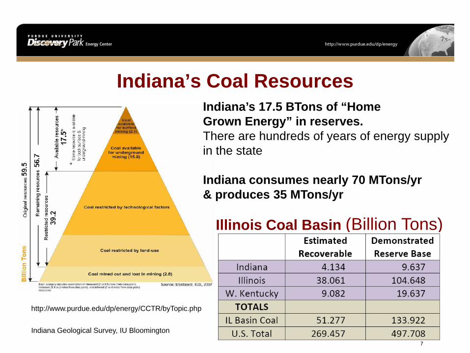
Indiana’s Coal ResourcesIndiana’s 17.5 BTons of “Home Grown Energy” in reserves.There are hundreds of years of energy supply in the state
Indiana consumes nearly 70 MTons/yr & produces 35 MTons/yr
Illinois Coal Basin (Billion Tons)
http://www.purdue.edu/dp/energy/CCTR/byTopic.php
Indiana Geological Survey, IU Bloomington
7

2007 Coal Destination: Indiana
8

Duke Energy Indiana, Edwardsport,630MW IGCC (800 MW)
(2) Wabash ValleyIGCC plant ~ one of
the two IGCC power plants in the USA
9

Edwardsport IGCC
Rob Burch, Duke Energy, Purdue University, April 16, 2009 10

Duke Energy IndianaEdwardsport 630MW IGCC (800 MW)
Rob Burch, Duke Energy, Purdue University, April 16, 2009 11
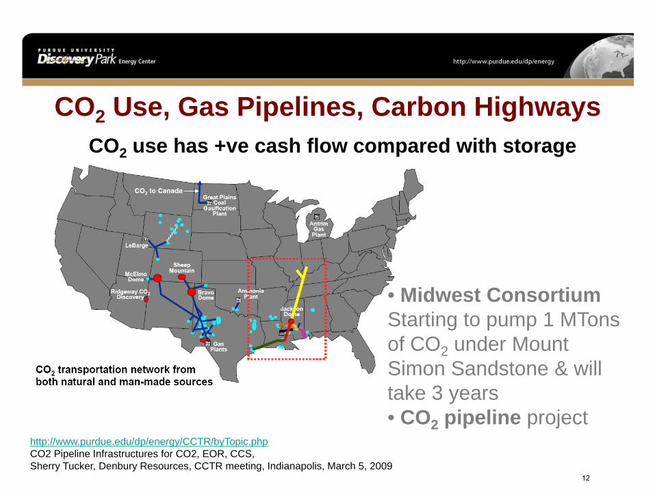
CO2 Use, Gas Pipelines, Carbon Highways
• Midwest Consortium Starting to pump 1 MTonsof CO2 under Mount Simon Sandstone & will take 3 years• CO2 pipeline project
http://www.purdue.edu/dp/energy/CCTR/byTopic.phpCO2 Pipeline Infrastructures for CO2, EOR, CCS, Sherry Tucker, Denbury Resources, CCTR meeting, Indianapolis, March 5, 2009
CO2 use has +ve cash flow compared with storage
12

Underground Coal Gasification, UCGCCTR & Purdue School of Chemical Engineering
UCG reduces capital expenditure & stores CO2Indiana site selection assessments
http://www.purdue.edu/dp/energy/CCTR/byTopic.php 13

CCTR Investigations into CTL Site Selection10 Criteria1 Coal & natural gas availability for 10,000 B/D
FT fuel2 CO2 sequestration potential3 Land/real-estate requirements4 Transportation infrastructure (rail, roads &
waterways)5 Electricity transmission lines & available
power6 Gas & oil pipelines7 Water requirements & resources8 Waste disposal/environmental issues9 Labor force requirements/availability10 Economic impacthttp://www.purdue.edu/dp/energy/CCTR/byTopic.php
14

Indiana Gasification LLC• Using Indiana coal to produce synthetic gas
• In 2007, the Indiana General Assembly enacted legislation that provided a tax credit for Indiana Gasification LLC to build a gasification plant in Southwest Indiana
Indiana Geological SurveyThe CCTR works closely with the Indiana Geological Survey: Coal characteristics, coal slurry project, coal maps, UCG, CO2 content
15

Indiana’s Coke & Rail NetworkCCTR & Purdue CalumetHow to replace the6 Million tons (+) ofimported metallurgicalcoal with Indiana coal
CCTR & Purdue North CentralSoftware modeling of optional expansion and operational plans of the railroad network in Indiana
http://www.purdue.edu/dp/energy/CCTR/byTopic.php 16

CTL, Slurry Reuse, Economic Studies
http://www.purdue.edu/dp/energy/CCTR/byTopic.php
• Coal-To-Liquids, CTL options• Reuse of coal slurry ponds• CTL Economics Study• Illinois Basin Alliance Study
17

Oxy-Fuel Combustion: Laboratory and Pilot Scale Experiments
E. J. Miklaszewski, Y. Zheng, and S. F. SonDepartment of Mechanical Engineering
Purdue UniversityWest Lafayette, IN 47907
18

Laboratory Experiments - Objectives and Apparatus
Oxy-Coal Dust Cloud CombustionExperiment Configuration
ObjectivesDocument•Flame Speed•Spectral Radiation
Vary•Coal type•Particle size•Oxygen content•Diluent
19

Laboratory Experiments – Results (Spectral)
Fast Infrared Array Spectrometer (FIAS)
•Portable•Staggered PbSe linear array sensor cooled by TEC•160 wavelengths from 1.4 to 4.8 um•Scan frequency: 6,250 Hz •Acquisition frequency: 1,320 Hz
20

Laboratory Experiments – Results (Spectral)
Test Specs:40% CO2, 60% O2Particle Dia – 25-53 micronsCloud density - 0.539 kg/m3
ignition
t = 40ms
t = 20ms
t = 30ms
t = 10ms
t = 160ms(MaximumRadiation)
0.0E+00
5.0E+03
1.0E+04
1.5E+04
2.0E+04
2.5E+04
3.0E+04
1.00 1.50 2.00 2.50 3.00 3.50 4.00
Inte
nsity
(W
/m2-
sr-μ
m)
Wavelength (μm)
Ignition
t=10ms
t=20ms
t=30ms
t=40ms
t=160ms (Max Specal Radiation)
21

Laboratory Experiments – Results (Flame Speed)
Effect of Diluent On Flame Speed
0
1
2
3
4
5
6
7
8
0 10 20 30 40 50 60 70
Flam
e Sp
eed
(m/s
)
Average Particle Diameter (microns)40% O2/ 60% Diluent
CO2 N2
Trends similar to that seen in:Suda T, Masuko K “Effect of carbon dioxide on flame propagation of pulverized coal clouds in CO2/O2 combustion”, Fuel (2007), doi:10.1016/j.fuel.2006.11.038
22

Laboratory Experiments – Results (Spectral)
Trends•Same General Shape•Peak at 2.7 microns for Water and CO2
0.0E+00
5.0E+03
1.0E+04
1.5E+04
2.0E+04
2.5E+04
3.0E+04
3.5E+04
1.00 1.50 2.00 2.50 3.00 3.50 4.00
Inte
nsity
(W
/m2-
sr-μ
m)
Wavelength (μm)
30% O2 25-53 microns
40% O2 25-53 microns
40% O2 50-75 microns
0.0E+00
5.0E+03
1.0E+04
1.5E+04
2.0E+04
2.5E+04
3.0E+04
1.00 1.50 2.00 2.50 3.00 3.50 4.00
Inte
nsity
(W
/m2-
sr-μ
m)
Wavelength (μm)
60% O2 25-53 microns
40% O2 25-53 microns
40% O2 50-75 microns
CO2 DiluentN2 Diluent
23

Pilot Scale Experiments
From Jupiter Oxygenin Hammond, Indiana
24

Pilot Scale Experiments - Objectives
The Pilot Scale Boiler• Doosan Backcock 23.4 MW boiler• Four Maxson 2.93 MW• Total heating rate during tests: < 8.79 MW
Test Matrix • HT oxy-natural gas without CO2 recycling• HT oxy-natural gas with CO2 recycling (blanket)*• LT oxy-natural gas with CO2 recycling (synthetic air)• Air firing natural gas• HT oxy-coal without CO2 recycling
* http://www.jupiteroxygen.com 25

Wall
FlameFront
FIAS
BurnerAssembly
Spectral Measurement Configuration
Pilot Scale Experiments – Pilot Scale Apparatus
26

Pilot Scale Experiments – Results
Comparison of estimated temperature profiles
Peak temperatures of HT oxy-fuel flames are MUCH higherTemperatures of LT oxy-fuel air-firing flames are comparable Gas temperature near the wall of the HT oxy-fuel without FGR configuration is the highest
Burner center r
0.0 0.2 0.4 0.6 0.8 1.0
T, K
1000
1500
2000
2500
3000
3500
LT Oxy-fuelAir-firingHT Oxy-fuel w/ FGR HT Oxy-fuel w/o FGR
Side wall
27

We’d like to thank Prof. Timothee Pourpoint for use of his Matlab Code for analyzing the high-speed images.
We thank Jupiter Oxygen engineers for gathering the data and providing pilot scale apparatus. In particular, we thank Brian Patrick and Steve Nied.
We thank the Center for Coal Technology Research for funding under contract number 7-PSC-CTR-002. In particular, we thank Marty Irwin and Brian Bowen for their support of this work.
Acknowledgements
28

Appenix
Coal Type - Indonesian Coal
Coal Classification - Bituminous (low sulfur, low ash)
Ultimate Analysis (%)
Carbon - 73.70% Hydrogen - 5.20% Oxygen - 18.80%
Nitrogen - 1% Sulfur - 0.10%
Ash - 1.30%
Typical Proximate Analysis (%)
Moisture - 16.12% Ash - 1.06%
Volatile - 42.59% Fixed Carbon - 40.23%
0
1
2
3
4
5
6
7
8
9
1 10 100 1000Vo
lum
e (%
)Particle Diameter (μm)
Further Classify Coal using Sieves:• >106 µm• 106 µm - 75 µm • 75 µm - 53 µm• 53 µm - 25 µm• < 25 µm
Coal Analysis
29

Appendix
y = 1.5976x - 24.993R² = 0.9788
y = 4.0318x - 3.7535R² = 0.9953
0
10
20
30
40
50
60
70
80
90
0 10 20 30 40 50 60
Flam
e Ef
fect
ive
Dia
met
er (m
m)
Time (ms)
Coal Diameter (25-53μm)
Coal Diameter <25μm
How Flame Speed was Obtained
Both cases:Cloud density - 0.539 kg/m3
40% O2 and 60% CO2 30

Laboratory Experiments – Results (Flame Speed)
0
0.5
1
1.5
2
2.5
3
3.5
4
4.5
0 20 40 60 80
Flam
e Sp
eed
(m/s
)
Average Particle Diameter (μm)
Effect of Particle Diameter On Flame Speed
All cases:Cloud density - 0.539 kg/m3
40% O2 and 60% CO2
Dia. <25 μm Dia. 53-75 μm
31

Laboratory Experiments – Results (Flame Speed)
Effect of Oxygen On Flame Speed
0
1
2
3
4
5
6
7
30 40 50 60 70
Flam
e Sp
eed
(m/s
)
O2 (% by Volume)
All cases:Cloud density - 0.539 kg/m3
Particle Dia. – 25-53 μmCarbon Dioxide Diluent
60% O2 40% O2
32

Appendix – Results (Spectral)
Trends All cases:Cloud density - 0.539 kg/m3
0.0E+00
5.0E+03
1.0E+04
1.5E+04
2.0E+04
2.5E+04
3.0E+04
3.5E+04
1.00 1.50 2.00 2.50 3.00 3.50 4.00
Inte
nsity
(W
/m2-
sr-μ
m)
Wavelength (μm)
40% O2; 60% N2 25-53 microns
40% O2; 60% CO2 25-53 microns
33

Laboratory Experiments – Results (Spectral)
Trends All cases:Cloud density - 0.539 kg/m3
0.0E+00
5.0E+03
1.0E+04
1.5E+04
2.0E+04
2.5E+04
3.0E+04
1.00 1.50 2.00 2.50 3.00 3.50 4.00
Inte
nsity
(W
/m2-
sr-μ
m)
Wavelength (μm)
Coal Types w CO2
Indonesian Low Ash Illinois Coal #6
34

The temperature profile was described as the following:
•Assumed Temperature Profile and best fit to boundary conditions and spectral data
•First time this technique applied to coal and pilot scale experiments
2
( ) exp pp b
r rT r T T
c
⎡ ⎤−⎛ ⎞= − +⎢ ⎥⎜ ⎟
⎢ ⎥⎝ ⎠⎣ ⎦
Appendix – Inverse Flame Temperature Technique
35

Appendix - Pilot Scale Experiments – Results
Test 23, IR Port 2 (0)
λ, μm
2.5 3.0 3.5 4.0 4.5
I λ, W
/m2 -s
r-μm
0
15000
30000
45000
60000
75000Meas.Pred.
Test 24, IR Port 2 (0)
λ, μm
2.5 3.0 3.5 4.0 4.5
I λ, W
/m2 -s
r-μm
0
10000
20000
30000
40000
50000 Meas.Pred.
Test 30, IR Port 2 (0)
λ, μm
2.5 3.0 3.5 4.0 4.5
I λ, W
/m2 -s
r-μm
0
5000
10000
15000
20000
25000 Meas.Pred.
Test 34, IR Port 2 (0)
λ, μm
2.5 3.0 3.5 4.0 4.5
I λ, W
/m2 -s
r-μm
0
5000
10000
15000
20000
25000 Meas.Pred.
Spectral Emissions of HT oxy-fuel w/o CO2recirculation
Spectral Emissions of HT oxy-fuel w/ CO2recirculation
Air-Fire Spectral Emissions
LT oxy-fuel Spectral Emissions (Synthetic Air with FGR)
36

Appendix
Study Other CoalsRepeatability StudyModify Inverse Temperature Estimate Code for dust cloudsAnalysis of Dust Clouds
37

Combustion and Propulsion Laboratory
Li Qiao, Ph.D.Assistant ProfessorSchool of Aeronautics and Astronautics(By courtesy in Mechanical Engineering)Purdue [email protected]
A sequence of photographs of flame surface propagation for a toluene/air flame at 400 K and 1 atm: fuel-rich (top), fuel-lean (bottom).
Simultaneous with efforts to increase the fuel efficiency and decrease the environmental impact of power generation systems, a new, diversified fuel source future is emerging in the marketplace as we move forward into the new century. Reliable design and optimization of advanced energy conversion systems will rely on a fully understanding of the chemical and physical properties of fuels. The next generation fuels are likely to be much different from current fuels. These fuels will be produced from alternative sources such as oil sands, oil shale, coal, as well as from a variety of biomaterials, all of which are fundamentally different from current petroleum-based fuels. New alternative fuels can be even more complex with increased fractions of compounds such as oxygenates napthenes and olefins, whose chemical properties and combustion kinetics are poorly known. The objective of this project is to study ignition, burning rate, chemistry, and molecular transport of surrogate and alternative fuels by a combined experimental and modeling study.
Burning Rate, Chemistry and Transport Properties of Alternative Fuels
Flame speed of toluene/air flames as a function of φ at 400 K.
38

Combustion and Propulsion Laboratory
Li Qiao, Ph.D.Assistant ProfessorSchool of Aeronautics and Astronautics(By courtesy in Mechanical Engineering)Purdue [email protected]
Plasma-assisted ignition and combustion has a significant impact for civilian applications, including energy efficiency, fuel flexibility, and pollution reduction. Designing new combustion devices with high efficiency and low emission is always of special importance in the context of global energy crisis and the threat of global warming. On the other side, in military applications, scramjets, pulse detonation engines, and gas turbines are primary energy conversion devices whose performances have been limited, or, in some cases, not achieved because of technological deficiencies in stable ignition and low-loss flameholding in combustors. Plasma-based approaches already have attracted joint Air Force-Navy attention to remediate these difficulties for pulse detonation engines and are receiving substantial basic and applied Air Force research support for the scramjet application. The objective of the proposed research is to understand the physical and chemical effects of plasma-generated excited species, ions and electrons on laminar flames both experimentally and computationally.
Optical Diagnostics and Kinetic Mechanisms of Plasma-Enhanced Ignition and Combustion
Experimental diagram for simultaneous PIV/OH PLIF measurements in the counterflow flames.
Fuel
AnodeCathode
Quatzwindow
Air
Magnet
Flame
Low pressure chamber
Vacuum
Power supply
Sketch of the plasma/flame interaction experiment.
39

Combustion and Propulsion Laboratory
Li Qiao, Ph.D.Assistant ProfessorSchool of Aeronautics and Astronautics(By courtesy in Mechanical Engineering)Purdue [email protected]
Coal is the energy for future. Coal consumption will increase under any foreseeable scenario because it is cheap and abundant. However, coal has serious environmental problems that need to be addressed, particularly the green house gas emission. Oxy-coal combustion and CO2 capture from the flue gases is a near-zero emission technology that can be adapted to both new and existing pulverized coal-fired power plants. In oxy-combustion boilers, pulverized coal is carried by and burned with a mixture of O2 and recirculated flue gas (RFG), mainly CO2 (predominant) and water vapor. By recycling the flue gas, a gas consisting mainly of CO2 and water is generated, ready for sequestration without stripping of the CO2 from the gas stream.
Due to the high O2 concentration and the presence of flue gas CO2, the heat transfer profiles and combustion characteristics will be very different from the conventional air combustion. The objective of this project is to study the combustion and radiative heat transfer properties of laminar premixed oxy-coal flames by a combined experimental and modeling study.
Combustion and Heat Transport Characteristics In Oxy-Coal Flames
Photographs of the fluidized bed and the flat dust flame burner.
40


