35 1. Introduction With an increasing demand of energy resources, con- ventional energy is one of the most vital energy resources that become more expensive and scarce. Thus there is a need to generate power from renewable sources that help reduce the demand of fossil fuels and to save non- renewable sources for future generation. Renewable energy is natural energy which does not have a limited supply. Renewable energy can be used again and again, and will never run out. Wind power is the most common form of renewable energy. Here, electricity is generated by blades turning turbines which run a generator. Wind power has a potentially infinite energy supply and a number of advantages to its use. Wind is a free commo- dity and is in infinite supply and thus an affordable rene- wable energy source. Further, generating wind does not produce toxins or pollutants to the environment and thus assists in the fight against global warming. Figure 1 shows below the development of wind power in the past decade (GWEC) 2010. Wind turbines are mainly Horizontal Axis Wind Turbine (HAWT) and Vertical Axis Wind Turbine (VAWT). The Savonius type vertical axis wind rotor was first invented by S. J. Savonius in 1929 [1]. The design was based on the principle of Flettner's rotor. The rotor was formed by cutting a Flettner's cylinder from top to bottom and then moved the two semi-cylinder surfaces sideways along the cutting plane so that the cross-section resembled the letter 'S'. To determine the best geometry, Savonius tested 30 different models in the wind tunnel as well as in the open air. The best of his rotor models had power coefficient (C p ) of 31%, and the maximum C p of the prototype in the natural wind was 37%. Applications of Savonius rotor, in general, includes pumping water, driving an electrical generator, providing Abstract T his paper produces the quantitative predica- tions of fluid flow pheno- mena based on this conser- vation laws (conservation of mass, momentum, and energy) governing fluid flow motion. For this, a two bu- cket savonius rotor with shaft was designed using GAMBIT, having a height of 60 cm and diameter of 17 cm. A two dimensional Computational Fluid Dynamics (CFD) analysis using Fluent package was done to predict the performance of the two-bucket Savonius rotor. The standard k-ε turbu- lence model with standard wall condition was used. The Second order upwind discretization scheme was adopted for pressure-velocity coupling of the flow. The analysis of the static pressure (Pas- cal) was done at a different bucket position from 0° to 360° in a step of 45° rotor angle in a complete cycle of rotation corresponding to the flow direction. And it is observed from the ana- lysis that the maximum change in static pressure from the upstream side of the rotor to the downstream side of the rotor is at 90° and 270° rotor angle against the flow direction. Thus at this rotor angle couple is produce and reduce the nega- tive wetted area and hence high torque and high rpm generate which helps to improve the power coefficient. Keywords: Two-bucket Savonius rotor, Static torque, Power coefficient. Fluid Flow Analysis of Savonius Rotor at Different Rotor Angle Using CFD 1 Bachu Deb and 2 Rajat Gupta 1 Assistant professor, Department of Mechanical Engineering, NIT Mizoram 2 Professor & Director, Department of Mechanical Engineering, NIT Srinagar 2 [email protected]Silchar - 788010, Assam, India 1 E-mail:[email protected]Volume 8 - Number 14 - November 2012 (35-42) ISESCO JOURNAL of Science and Technology
Transcript
35
1. Introduction
With an increasing demand of energy resources, con-ventional energy is one of the most vital energy resourcesthat become more expensive and scarce. Thus there is aneed to generate power from renewable sources that helpreduce the demand of fossil fuels and to save non-renewable sources for future generation. Renewableenergy is natural energy which does not have a limitedsupply. Renewable energy can be used again and again,and will never run out. Wind power is the most commonform of renewable energy. Here, electricity is generatedby blades turning turbines which run a generator. Windpower has a potentially infinite energy supply and anumber of advantages to its use. Wind is a free commo-dity and is in infinite supply and thus an affordable rene-wable energy source. Further, generating wind does notproduce toxins or pollutants to the environment and thus
assists in the fight against global warming. Figure 1 showsbelow the development of wind power in the past decade(GWEC) 2010. Wind turbines are mainly HorizontalAxis Wind Turbine (HAWT) and Vertical Axis WindTurbine (VAWT). The Savonius type vertical axis windrotor was first invented by S. J. Savonius in 1929 [1]. Thedesign was based on the principle of Flettner's rotor. Therotor was formed by cutting a Flettner's cylinder fromtop to bottom and then moved the two semi-cylindersurfaces sideways along the cutting plane so that thecross-section resembled the letter 'S'. To determine thebest geometry, Savonius tested 30 different models inthe wind tunnel as well as in the open air. The best of hisrotor models had power coefficient (Cp) of 31%, and themaximum Cp of the prototype in the natural wind was37%. Applications of Savonius rotor, in general, includespumping water, driving an electrical generator, providing
Abstract
This paper produces thequantitative predica-
tions of fluid flow pheno-mena based on this conser-vation laws (conservationof mass, momentum, andenergy) governing fluid flowmotion. For this, a two bu-cket savonius rotor withshaft was designed usingGAMBIT, having a heightof 60 cm and diameter of 17 cm. A two dimensionalComputational Fluid Dynamics (CFD) analysis usingFluent package was done to predict the performance ofthe two-bucket Savonius rotor. The standard k-ε turbu-lence model with standard wall condition was used. TheSecond order upwind discretization scheme was adoptedfor pressure-velocity coupling of the flow. The analysis
of the static pressure (Pas-cal) was done at a differentbucket position from 0° to360° in a step of 45° rotorangle in a complete cycleof rotation correspondingto the flow direction. And itis observed from the ana-lysis that the maximumchange in static pressurefrom the upstream side ofthe rotor to the downstreamside of the rotor is at 90°
and 270° rotor angle against the flow direction. Thus atthis rotor angle couple is produce and reduce the nega-tive wetted area and hence high torque and high rpmgenerate which helps to improve the power coefficient.
V o l u m e 8 - N u m b e r 1 4 - N o v e m b e r 2 0 1 2 ( 3 5 - 4 2 )
ISESCO JOURNAL of Science and Technology
Bachu&Gutpa 7/11/12 11:37 Page 35
Bachu Deb and Rajat Gupta / ISESCO Journal of Science and Technology - Volume 8, Number 14 (November 2012) (35-42)
36
ventilation, and agitating water to keep stock ponds ice-free during the winter [2-5]. Recently, there had beensome works done as to incorporate some modificationsin blade design to make it useful for small-scale powerrequirements. Research conducted by Grinspan [6] inthis direction led to the development of a new bladeshape with a twist for the Savonius rotor. The maximumpower coefficient (Cp) of 0.5 was reported by him. Guptaet al. [7] concentrate on three-bucket savonius rotorwith a three-bucket savonius darrieus rotor. They foundthat the power coefficient obtained by the combinedsavonius darrieus attained maximum efficiency of 51%.Gupta et al. [8] studied the flow physics of a three-bucketsavonius rotor with four overlap conditions in the rangeof 12.37% to 25.87% to find the optimum overlap i.e.19.87% which is responsible for maximum powerextraction by the rotor. Bach et al. [9] made some inves-tigations of the S-rotor and related machines. The highestmeasured efficiency was 24%. McPherson et al. [10] re-ported a highest efficiency of 33% and the maximumpower coefficient obtained by Newman et al. [11] wasonly 20%. Modi et al. [12] reported a power coefficientof 0.22. In the present study, the performance of two-bucket savonius rotor was investigated computationallyby using Fluent 6.0 CFD software.
2. Physical Model
Savonius rotor is a vertical axis wind turbine, itsconstruction is very simpler and called as S-type rotori.e. two semi-circular buckets. The mechanism of theconventional Savonius rotor is the difference of the dragforce exerted by wind on advancing and returning bucket.It pushes the rotor to rotate and hence wind energy istransferred into mechanical energy. The two-bucket
Savonius rotor is shown in Figure 2. The height of therotor (H) is 60cm, radius of the bucket (R) is 8.5 cm, andthe diameter of the shaft (d) is 3.5 cm. The buckets werespaced 1800 apart and were fixed to the central shaft withnut and bolt arrangements.
3. Computation zone
The two-bucket Savonius rotor were analyzed in avariation of complete cycle of rotation from 0° to 360°in a step of 45° rotor angle. The bucket were placed atdifferent rotor position against the flow direction are shownin Figure 3 below. A two dimensional steady state, 2nd
order upwind discretization method was adopted forpressure-velocity coupling of the flow.
Figure 1. Global cumulative install capacity of wind mill
Bachu Deb and Rajat Gupta / ISESCO Journal of Science and Technology - Volume 8, Number 14 (November 2012) (35-42)
37
4. Mathematical Formulation
Mathematical model can be defined as the combinationof dependent and independent variables and relativeparameters in the form of a set of differential equationswhich defines and governs the physical phenomenon. Inthe following subsections differential form of the gover-ning equation are provided according to the compu-tational model and their corresponding approximationand idealizations.
4.1. Continuity Equation:
The conservation of mass equation or continuityequation is given by
Where ρ is the density, is the velocity vector.
4.2. Momentum Equation:
Applying the Newton's second law (force = mass xacceleration) the conservation of momentum equationis given by
Where ρ is the density, is the velocity vector, p isthe static pressure, and is the stress tensor, and and
are the gravitational body force and external bodyforces.
4.3. Energy Equation
Energy is neither created nor destroyed. It is alwaysconserved.
The conservation of energy equation is given by
Where keff is the effective conductivity (k + kτ , where
kτ is the turbulent thermal conductivity), and is thediffusion flux of species j.
4.4. Turbulence Model
In this study Standard k-ε turbulence model has beenused with logarithmic surface function in the analysis ofturbulent flow [13]. Momentum equation, x, y and zcomponents of velocity, turbulent kinetic energy (k) anddissipation rate of turbulent kinetic energy (ε) have eachbeen solved with the use of the program. All theseequations have been made by using the iteration methodin such a way as to provide each equation in the centralpoint of the cells, and secondary interpolation methodwith a high reliability level has been employed. In thepresent study, the standard k-ε turbulence model withstandard wall condition was used.
The standard k- ε equations can be represented as:
Figure 3. Position of advancing bucket at different rotor angle
(1)
(2)
(3)
(4)
(5)
Bachu&Gutpa 7/11/12 11:37 Page 37
Bachu Deb and Rajat Gupta / ISESCO Journal of Science and Technology - Volume 8, Number 14 (November 2012) (35-42)
38
5. Mesh Generation & Boundary Condition
Mesh generation [14] constitutes one of the most im-portant steps during the pre-process stage after the defi-nition of the domain geometry. CFD requires the sub-division of the domain into a number of smaller, non-overlapping subdomains in order to solve the flow physicswithin the domain geometry that has been created; thisresults in the generation of a mesh (or grid) of cells (ele-ments or control volumes) overlaying the whole domaingeometry. The accuracy of a CFD solution is governedby the number of cells in the mesh within the compu-tational domain.
6. Contour Analysis of a two-bucketSavonius rotor
Contour plotting presents useful and effective graphic
technique that is frequently utilized in viewing CFD
results. In CFD, contour plots are one of the most com-
monly found graphic representations of data. The flow
field was analyzed under steady-state condition for Rey-
nolds number of Re>105. For the two-bucket savonius
rotor, the contours of static pressure were obtained for
different rotor angles: namely 0°, 45°, 90°, 135°, 180°,
225°, 270°& 315°. Figure 5 (a) to Figure 5 (h) show the
static pressure contours of two-bucket savonius rotor at
different rotor angle. These contours potray the variations
of the static pressure across the rotor. Figure 5 (a) shows
that at 0° rotor angle, the maximum change in static pres-
sure at the upstream side of the concave surface will
occur at 51.5 Pascal whereas at downstream side of the
concave surface is at -92.3 Pascal. At 45° rotor angle
Figure 5 (b), the static pressure decreases from upstream
side of the concave surface to the downstream side of
the convex surface i.e. 96.63 Pascal to -370.71 Pascal.
However, at 90° rotor angle Figure 5 (c) there is a drastic
change in static pressure from 621.02 Pascal to 597.20
Pascal from upstream side to the downstream side of the
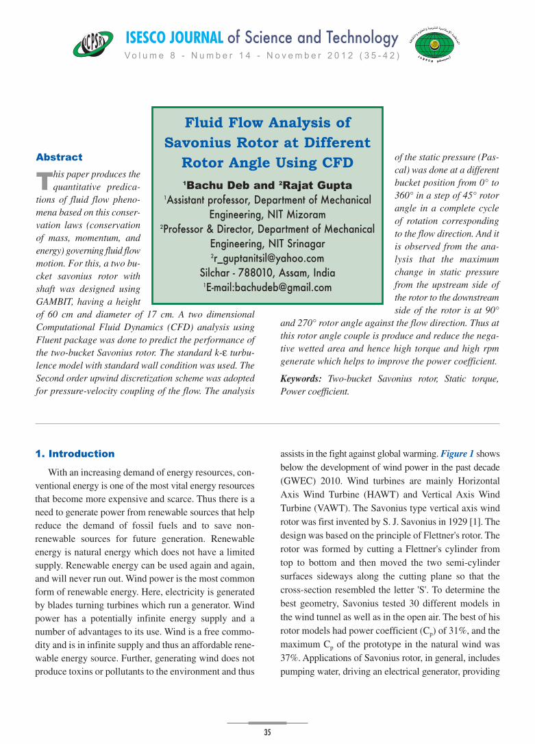
rotor. At 135° rotor angle Figure 5 (d), static pressure
decreases from 148.45° Pascal to -230.15 Pascal from up-
stream side of concave surface to downstream side of the
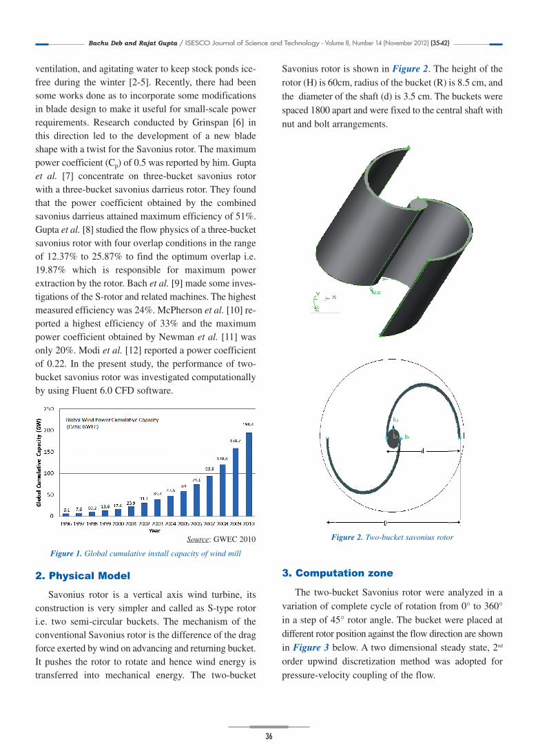
convex surface. Similarly at 180° rotor angle Figure 5 (e),
static pressure decreases from 76.66 Pascal to -102.37
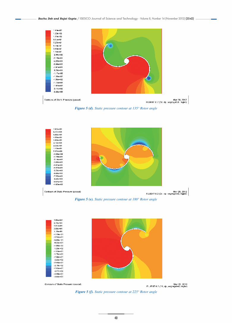
Pascal from upstream side to downstream side. At 225°
rotor angle Figure 5 (f), static pressure decreases from
105.30° Pascal to -363.68 Pascal from upstream side to
downstream side. At 270° rotor angle Figure 5 (g), static
pressure decreases from 411.52 Pascal at upstream side
to -1005.40 Pascal at downstream side. As shown in
Figure 5 (h), the maximum decrease in static pressure
from upstream side to downstream side is 209.42 Pascal
to -336.70 Pascal.
Figure 4. Computational mesh around two-bucket savonius rotor
TABLE 1. Boundary condition of two-bucket savonius rotor
Boundary condition
Inlet: Velocity Inlet
Sides: Symmetry
Bucket: Wall
Outlet: Pressure Outlet
Turbulence level 1%
Bachu&Gutpa 7/11/12 11:37 Page 38
Bachu Deb and Rajat Gupta / ISESCO Journal of Science and Technology - Volume 8, Number 14 (November 2012) (35-42)
39
Figure 5 (a). Static pressure contour at 0° Rotor angle
Figure 5 (b). Static pressure contour at 45° Rotor angle
Figure 5 (c). Static pressure contour at 90° Rotor angle
Bachu&Gutpa 7/11/12 11:37 Page 39
Bachu Deb and Rajat Gupta / ISESCO Journal of Science and Technology - Volume 8, Number 14 (November 2012) (35-42)
40
Figure 5 (f). Static pressure contour at 225° Rotor angle
Figure 5 (e). Static pressure contour at 180° Rotor angle
Figure 5 (d). Static pressure contour at 135° Rotor angle
Bachu&Gutpa 7/11/12 11:37 Page 40
Bachu Deb and Rajat Gupta / ISESCO Journal of Science and Technology - Volume 8, Number 14 (November 2012) (35-42)
41
Figure 5 (g). Static pressure contour at 270° Rotor angle
Figure 5 (h). Static pressure contour at 315° Rotor angle
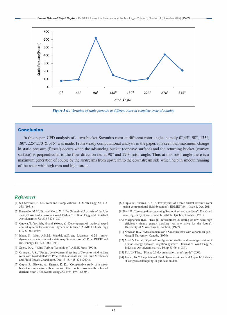
Figure 5 (i) shows below the change of static pressure(Pascal) at different rotor angle in a complete cycle ofrotation. From this analysis, it is found that maximumchange in static pressure occurs from rotor angle 45° to90° and then again it sharply decrease from 135° to 225°.
Thus from this analysis it can be concluded that when theadvancing bucket is at 45° and 270° rotor angle againstflow direction is responsible for maximum generation ofdrag forces and hence drastic change in static pressure.
Bachu&Gutpa 7/11/12 11:37 Page 41
Bachu Deb and Rajat Gupta / ISESCO Journal of Science and Technology - Volume 8, Number 14 (November 2012) (35-42)
42
Conclusion
In this paper, CFD analysis of a two-bucket Savonius rotor at different rotor angles namely 0°,45°, 90°, 135°,180°, 225°,270°& 315° was made. From steady computational analysis in the paper, it is seen that maximum changein static pressure (Pascal) occurs when the advancing bucket (concave surface) and the returning bucket (convexsurface) is perpendicular to the flow direction i.e. at 90° and 270° rotor angle. Thus at this rotor angle there is amaximum generation of couple by the airstreams from upstream to the downstream side which help in smooth runningof the rotor with high rpm and high torque.
[1] S.J. Savonius, “The S-rotor and its applications”. J. Mech. Engg. 53, 333-338 (1931).
[2] Fernando, M.S.U.K. and Modi, V. J. “A Numerical Analysis of the Un-steady Flow Past a Savonius Wind Turbine”. J. Wind Engg and IndustrialAerodynamics 32, 303-327 (1989).
[3] Ogawa, T., Yoshida, H. and Yokota, Y. “Development of rotational speedcontrol systems for a Savonius type wind turbine”. ASME J. Fluids Enggl11, 53-58 (1989).
[4] Islam, S., Islam, A.K.M., Mandal, A.C. and Razzaque, M.M., “Aero-dynamic characteristics of a stationary Savonius rotor”. Proc. RERIC andInt.J.Energy 15, 125-136 (1993).
[6] Grinspan, A.S., “Design, development & testing of Savonius wind turbinerotor with twisted blades”. Proc. 28th National Conf. on Fluid Mechanicsand Fluid Power. Chandigarh, Dec 13-15, 428-431 (2001).
[7] Gupta, R., Biswas, A., Sharma, K. K., “Comparative study of a three-bucket savonius rotor with a combined three bucket savonius -three bladeddarrieus rotor”. Renewable energy,33,1974-1981, (2008).
[8] Gupta, R., Sharma, K.K., “Flow physics of a three-bucket savonius rotorusing computational fluid dynamics”. IJRMET Vol.1.Issue 1, Oct. 2011.
[9] Bach G., “Investigation concerning S-rotor & related machines”, Translatedinto English by Brace Research Institute, Quebec, Canada, (1931).
[10] Macpherson R.B., “Design, development & testing of low head highefficiency kinetic energy machine- An alternative for the future”,University of Massachusetts, Amhest, (1972).
[11] Newman B.G., “Measurements on a Savonius rotor with variable air gap,”Macgill University, Canada, (1974).
[12] Modi V.J. et.al., “Optimal configuration studies and prototype design ofa wind energy operated irrigation system”, Journal of Wind Engg &Industrial Aerodynamics, vol. 16,pp 85-96, (1984).