25

<< Back Home next >>
OISD STANDARD131 First Edition, April 1990 Amended edition,
August, 1999 FOR RESTRICTED CIRCULATION
INSPECTION OF
BOILERS
Prepared by
COMMITTEE ON INSPECTION OF STATIC EQUIPMENT
OIL INDUSTRY SAFETY DIRECTORATE 7TH FLOOR, NEW DELHI HOUSE
27, BARAKHAMBA ROAD NEW DELHI – 110 001
NOTES
OISD publications are prepared for use in the Oil and gas industry under Ministry of Petroleum and Natural Gas. These are the property of Ministry of Petroleum and Natural Gas and shall not be reproduced or copied and loaned or exhibited to others without written consent from OISD.
Though every effort has been made to assure the accuracy and reliability of data contained in these documents, OISD hereby expressly disclaims any liability or responsibility for loss or damage resulting from their use. These documents are intended only to supplement and not replace the prevailing statutory requirements.
Note1 in superscript indicates the modification/changes/addition based on the amendments approved in the 17th Safety Council meeting held in July, 1999.

FOREWORD
The Oil Industry in India is 100 years old. Because of various collaboration agreements, a variety of international codes, standards and practices have been in vogue. Standardisation in design philosophies and operating and maintenance practices at a national level was hardly in existence. This, coupled with feed back from some serious accidents that occurred in the recent past in India and abroad, emphasized the need for the industry to review the existing state of art in designing, operating and maintaining oil and gas installations. With this in view, the Ministry of Petroleum & Natural Gas, in 1986, constituted a Safety Council assisted by Oil Industry Safety Directorate (OISD), staffed from within the industry, in formulating and implementing a series of self regulatory measures aimed at removing obsolescence, standardising and upgrading the existing standards to ensure safe operations. Accordingly, OISD constituted a number of Functional Committees of experts nominated from the industry to draw up standards and guidelines on various subjects. The present document on “Inspection of Boilers” has been prepared by the Functional Committee on “Inspection of Static Equipment”. This document covers in details the inspection requirements and procedure of boilers (i.e requirements of maintenance and inspection of equipment in service) and very briefly touches on inspection of equipment during construction and pre-commissioning. This document is based on the accumulated knowledge and experience of industry members and the various national and international codes and practices. This document is meant to be used as a supplement and not as a replacement for existing codes and practices. It is hoped that the provisions of this document, when adopted may go a long way to improve the safety and reduce accidents in the Oil and Gas Industry. Users are cautioned that no standard can be a substitute for judgment of a responsible qualified maintenance Engineer. Suggestions are invited from the users, after it is put into practice, to improve the document further.
This standard in no way supersedes the statutory
regulations of CCE, Factory Inspectorate or any other Govt. body which must be followed as applicable.
Suggestions for amendments to this document should be addressed to
The Co-ordinator, Committee on
“Inspection of Static Equipment,
OIL INDUSTRY SAFETY DIRECTORATE 7th Floor, ‘New Delhi House’
27, Barakhamba Road New Delhi – 110 001
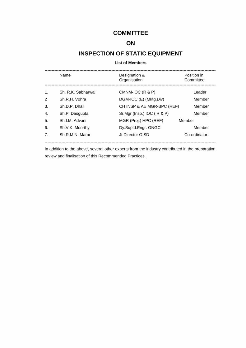
COMMITTEE
ON
INSPECTION OF STATIC EQUIPMENT
List of Members --------------------------------------------------------------------------------------------------------------------------- Name Designation & Position in Organisation Committee ---------------------------------------------------------------------------------------------------------------------------
1. Sh. R.K. Sabharwal CMNM-IOC (R & P) Leader
2 Sh.R.H. Vohra DGM-IOC (E) (Mktg.Div) Member
3. Sh.D.P. Dhall CH INSP & AE MGR-BPC (REF) Member
4. Sh.P. Dasgupta Sr.Mgr (Insp.) IOC ( R & P) Member
5. Sh.I.M. Advani MGR (Proj.) HPC (REF) Member
6. Sh.V.K. Moorthy Dy.Suptd.Engr. ONGC Member
7. Sh.R.M.N. Marar Jt.Director OISD Co-ordinator.
---------------------------------------------------------------------------------------------------------------------------
In addition to the above, several other experts from the industry contributed in the preparation,
review and finalisation of this Recommended Practices.

INSPECTION OF BOILERS
CONTENTS SECTION PAGE NO. 1.0 Introduction 2.0 Scope 3.0 Definitions and types of Boilers 3.1 Definition 3.2 Types of Boilers 4.0 Inspection Role 5.0 Inspection Tools 6.0 Inspection of Boiler During Fabrication 7.0 Check list for Inspection of Boilers Prior to Erection and Commissioning 7.1 Check list 7.2 Other Specific Requirements 7.2.1 Stream Drum 7.2.2 Economiser, Super Heater and Air Heater 7.3 Precommissioning Activities 8.0 Likely Location of Metal Wastage 8.1 Stream Drum 8.2 Combustion Chamber 8.3 Economiser 8.4 Super heater 8.5 Air-Preheater 8.6 Windbox and Air Duct 8.7 Blowdown Piping/soot Blower Piping 8.8 Expansion Bellows 8.8.1 Co Boiler Duct 8.8.2 Air duct Bellows 8.9 Boiler Feed Pipe Corrosion 9.0 Frequency of Inspection 9.1 On-Stream Inspection 9.2 Shutdown Inspection 10.0 Inspection Procedures 10.1 On-Stream(Water Tube Boilers) 10.1.1 Flame Condition 10.1.2 Excess Air 10.1.3 Condition of Refractory 10.1.4 Leaks 10.1.5 Hot Spots 10.1.6 Ladders, Stairways and Platforms 10.1.7 Boiler Feed 10.2 On-Stream (Fire Tube Boilers) 10.3 Inspection During Shutdown 10.3.1 External Inspection (Water Tube Boilers) 10.3.2 Internal Inspection 10.4 Internal Inspection (Fire Tube Boilers) 11.0 Waste Heat Boilers 12.0 Co-Boilers 13.0 Inspection During Repairs and Replacement 13.1 Repair/Replacement of Economiser

SECTION PAGE NO. 13.2 Drums 14.0 Record and documentation 15.0 References Annexure I (Weekly routine Boiler Inspection Report) Annexure II (Useful tests for the control of water for Boilers)
INSPECTION OF BOILERS
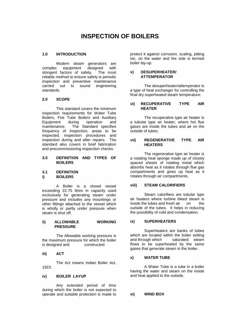
1.0 INTRODUCTION Modern steam generators are complex equipment designed with stringent factors of safety. The most reliable method to ensure safety is periodic inspection and preventive maintenance carried out to sound engineering standards. 2.0 SCOPE This standard covers the minimum inspection requirements for Water Tube Boilers, Fire Tube Boilers and Auxiliary Equipment during operation and maintenance. The Standard specifies frequency of Inspection, areas to be inspected, inspection procedures and inspection during and after repairs. The standard also covers in brief fabrication and precommissioning inspection checks. 3.0 DEFINITION AND TYPES OF
BOILERS 3.1 DEFINITION i) BOILERS A Boiler is a closed vessel exceeding 22.75 litres in capacity used exclusively for generating steam under pressure and includes any mountings or other fittings attached to the vessel which is wholly or partly under pressure when steam is shut off. ii) ALLOWABLE WORKING
PRESSURE The Allowable working pressure is the maximum pressure for which the boiler is designed and constructed. iii) ACT The Act means Indian Boiler Act, 1923. iv) BOILER LAYUP Any extended period of time during which the boiler is not expected to operate and suitable protection is made to
protect it against corrosion, scaling, pitting etc. on the water and fire side is termed boiler lay-up. v) DESUPERHEATER/
ATTEMPERATOR The desuperheater/attemperator is a type of heat exchanger for controlling the final dry superheated steam temperature. vi) RECUPERATIVE TYPE AIR
HEATER The recuperative type air heater is a tubular type air heater, where hot flue gases are inside the tubes and air on the outside of tubes. vii) REGENERATIVE TYPE AIR
HEATERS The regenerative type air heater is a rotating heat sponge made up of closely spaced sheets of rotating metal which absorbs heat as it rotates through flue gas compartments and gives up heat as it rotates through air compartments. viii) STEAM CALORIFIERS Steam calorifiers are tubular type air heaters where turbine bleed steam is inside the tubes and fresh air on the outside of the tubes. It helps in reducing the possibility of cold and condensation. ix) SUPERHEATERS Superheaters are banks of tubes which are located within the boiler setting and through which saturated steam flows to be superheated by the same gases that generate steam in the boiler. x) WATER TUBE A Water Tube is a tube in a boiler having the water and steam on the inside and heat applied to the outside. xi) WIND BOX

A Wind Box is a chamber surrounding a burner, through which air under pressure is supplied for combustion of the fuel. 3.2 TYPES OF BOILERS Fired Boilers are classified in two types: 1. Fire Tube Boilers 2. Water Tube Boilers i) FIRE TUBE BOILERS A fire tube boiler consists of a drum with a tube sheet on each end in which the fire tubes are fastened. Water is contained within the drum surrounding the fire tubes. Fuel is burnt in a combustion chamber associated with the boiler and arranged in such a manner, that flue gases pass through the inside of the fire tubes to heat the water surrounding them. These may be either externally fired in which the combustion chamber may be a refractory lined box which is located against one end of the drum or internally fired which may have a steel chamber located within the drum and also surrounded except on one end by the water in the drum. ii) WATER TUBE BOILER A water tube boiler consists of one or more(usually from two or four) drums with external banks of tubes connected between the two ends of a single drum or between the drums of multidrum boilers. In water-tube boilers the water is contained within the drums and within the tubes. The fuel is always burnt in an external combustion chamber and flue pass around the outside of the water tubes to heat the water within. Water tube boilers are further classified as straight tube and bent tube types. These may be long drum boiler with one or more drums or may be cross drum boilers. The tubes of most straight tube boilers are connected into a heater which in turn is connected to the boiler drums. Bent tube boilers are similar to straight tube boilers except that the tubes are almost always multidrum and are connected directly into the boiler drums. The tubes are bent in order to allow them
to enter the drums radially to facilitate installation, to allow for expansion and contraction and to allow for flexibility in design. 4.0 INSPECTION ROLE The following are the responsibilities of the inspection division. i) To inspect, measure and record the
deterioration of materials and to evaluate the physical condition of the boiler and its auxiliaries for its soundness to continue in service.
ii) To co-relate the deterioration rate with
design life for further run. iii) To determine causes of deterioration
and to advise remedial measures. iv) To recommend/forecast short term
and long term repairs and replacements.
v) To advise regarding components
/equipment replacement so that procurement action can be initiated.
vi) To undertake stage-wise inspection of
repairs. vii) To maintain upto date maintenance
and inspection records and history. viii) To keep the concerned operating and
maintenance personnel fully informed as to the present condition of boilers.
5.0 INSPECTION TOOLS The following inspection tools are generally used for carrying out the inspection of Boiler parts. 1. Ultrasonic Thickness Gauge 2. Ultrasonic Flaw detector 3. Radiography Equipment 4. Infra-red Scanner for
Thermography 5. Fibrescope/Boroscope 6. Dye Penetrant kit 7. Paint Thickness Gauge 8. ID & OD Gauges 9. Inspector’s Hammer 10. Pit Depth Gauge 11. Magnifying Glass 12. Plumb and Bob 13. Magnets

14. Small Mirror 15. Scraper 16. Measuring Tape 17. Safety Torch/Hand Lamp 18. Vacuum-Leak Detector Kit 19. Surveyor’s level 6.0 INSPECTION OF BOILER DURING
FABRICATION All boilers are designed and fabricated as per the various codes available like ASME, BS, IBR etc. Inspection of new Boiler at the time of fabrication shall be done as per applicable codes and statutory requirements. The inspection shall include the following: i) Study of the tender document and all
the technical specifications. ii) Identification and inspection of the
materials. iii) Approval of the welding procedures. iv) Approval of welders performance
qualification test. v) Check for nozzle orientation, joints
fitup and overall dimension as per the approved drawings.
vi) Check to ensure that the welding is
carried out as per approved welding sequence and procedures with approved electrodes and qualified welders.
vii) Inspection of the weld joints for proper
quality during welding. viii) Checks to ensure proper preheat and
post weld heat treatment wherever required.
ix) Inspection of weld joints by
radiography and other Non-Destructive Testing methods as specified.
x) Inspection of repairs, if any, before giving clearance for hydrostatic testing.
xi) Approval of the procedure for various
types of testing. xii) Checks to ensure that all the tests are
carried out strictly as per approved procedures.
xiii) Inspection of painting. xiv) Checks to ensure that the boiler has
been stamped. xv) Preparation and certification of the
relevant documents. 7.0 CHECKLIST FOR INSPECTION OF
BOILERS PRIOR TO ERECTION AND COMMISSIONING
The following erection and precommissioning checks shall be carried out for Boiler drums and other pressure parts: 7.1 CHECK LIST: ACTION REMARKS 1. Name plate details. 2. Check for proper
alignment of supports. 3. Inspection of foundation
bolts and shims. 4. Inspection of shell wall of
drums for mechanical damage.
5. Visual inspection of weld joints.
6. Inspection of alterations made during plant construction.
7. Wall thickness measurement of shell and nozzles.
8. Inspection and testing of reinforcement plates.
9. Inspection of nozzles, facing gaskets and bolts.
10. Inspection of outside bolting and stiffening rings.
11. Inspection of insulation of fire proofing.
12. Inspection of insulation protection.
13. Inspection of painting quality.
14. Inspection of internals. 15. Inspection for internal
cleanliness before final boxing up.
16. Inspection for proper safety relief valve installation.
17. Inspection to ensure that connected pipings do not strain the nozzles.
18. Inspection of all safety valve nozzles, water column nozzles, vent nozzles, pressure gauge nozzles for any obstruction.
7.2 SPECIFIC REQUIREMENTS In addition to above, some specific requirements for each boiler part as given under shall be fulfilled before commissioning. 7.2.1 Steam Drum i) That the steam separators are free
from deposits. ii) That all the wooden plugs have been
removed from tube ends. iii) That the drum is free to expand in all
the required directions. iv) That the water level gauge and water
level instruments connections have been installed as per approved drawings.
v) That drum pressure gauges have
been checked for calibration and functioning.
7.2.2 Economiser, Super Heater & Air
Heater i) Inspection of economiser, superheater
and airheater for transverse and longitudinal spacings. Any misalignment shall be corrected.
ii) Inspection for proper supports,
expansion clearances, vibration in the scrubbers, gas baffles etc. etc.
iii) Inspection for the proper position of
the soot blower nozzles in relation to the tubes for avoiding scouring of tubes by impingement during operation.
iv) Inspection of the thermocouple point of
correct location, installation, continuity and response.
v) Inspection to ensure that safety valve
vent pipes have been properly supported.
7.3 PRECOMMISSIONING ACTIVITIES The following test and activities shall carried out in addition to the normal start-up activities before boiler is made ready for operation. a) Air & Gas Tightness Tests The fire box and the ducting system shall be checked for leak tightness before applying insulation, painting or cladding etc. The dampers, access doors, observation ports and other openings shall be secured. Pressurised unit shall be subjected to pressure decay test of the boiler in addition to tightness test. Decay testing should be carried out at 1.5 times the maximum operating pressure. Air and gas tightness tests can be carried out by running the forced draft fan and maintaining a pressure of 50 mm in the ducting under test. Leaky portion shall be rectified and test shall be repeated to ensure satisfactory leak tightness of the system. b) Chemical cleaning Before a new boiler is put into service, the internal surface of steam generating section shall be chemically cleaned. This process includes boil out to remove grease followed by an acid cleaning to remove mill scales and rust. During the boil out period solution samples shall be taken periodically to monitor alkalinity, pH, Fe, silica and oil content. This operation is intended to remove mill scales, welding slag, debris or other foreign materials left over in the super heater, preheater and steam pipings of boiler. c) Safety Valve Setting At the end of steam blowing, the safety valves in the boiler shall be floated and set to operate at the design pressure. For details OISD Standard -132 on Pressure Relieving Devices shall be referred. d) Testing of Protections and Inter
Locks All the interlocks and protections provided for the individual equipments
shall be inspected and made functional before putting them into service. 8.0 LIKELY LOCATION OF METAL
WASTAGE 8.1 STEAM DRUM Shell or drum from water side may pit due to corrosive water and muck. During operation of steam boiler, the gases unusually evolved are oxygen, hydrogen and carbon dioxide and all are undesirable. Carbon dioxide with water in boiler forms carbonic acid. Thus acidity is increased and pH value decreases. If pH value of water is raised to 9.4 hydrogen evolution ceases and a protective film is formed over the anodic area. But presence of oxygen retards the above action. Hence, it is important to remove even the traces of oxygen from water. Due to poor performance of dearerator, dissolved oxygen in feed water causes the pitting internally. Grooving and cracks along the longitudinal weld seams may occur if the material is highly stressed. Severe corrosion is likely to occur at points where the circulation of water is poor. External surface of drum is likely to corrode due to wetting of insulation or improper insulation. 8.2 COMBUSTION CHAMBER Bulging in furnace tubes are caused due to flame impingement. If there is hard firing, the flame is likely to touch the furnace wall unevenly. Overheating is generally caused by increased steam and metal temperatures due to inadequate medium flow through the tubes or higher than designed heat transfer which subsequently causes blistering, quench cracking, sagging or bowing of tubes. Internal corrosion in the tubes is caused by poor maintenance of water quality. External corrosion is generally caused by moisture which accumulates on sulphur deposit, and flue gas condensation. This gives rise to external pitting and grooving in the outer wall tubes and mud drum at flue gas passage.
When flue gas and refractory are in contact at a moderately high temperature, a fluxing action may occur and produce a slag. The general effect on this slagging action is to decrease the insulating effect of the refractory and so allow high metal temperature on the supporting steel parts. The slagging effects of vanadium and sodium oxides may also cause rapid deterioration of tubes, tube hangers and spacers. 8.3 ECONOMISER External corrosion in the low temperature regions of economiser may occur due to flue gases cooling down to the dew point temperature. External erosion may be caused by high velocity steam from Soot blower. External deterioration may occur due to water impingement when adjacent tube fails. Internal corrosion is caused due to dissolved oxygen in feed water and thinning may take place at the bends due to erosion. 8.4 SUPERHEATER Superheater tubes can rupture if deposits accumulate in them. The cause of accumulation must be investigated and corrected. Excessive height of water maintained in the drum or deposits accumulated on steam separators may cause carry over and subsequent superheater tube failures. Warping of superheater elements is an indication of overheating too rapidly or failure to open the drain when raising pressure. Overheating of super heater tubes is likely if steam is interrupted. 8.5 AIR-PREHEATER Due to poor combustion, especially during start up or shutdown, oil carry over and deposition occur in the air heaters. These deposits have to be cleaned by soot blowing or by water washing during shutdown: otherwise under conductive conditions, they will catch fire and lead to a major failure or air heater tubes. Low temperature corrosion of the cold end is a common problem with unit operating on fuel with high sulphur content. The life of cold end tubes can be
prolonged by maintaining the cold end metal temperature above the acid dew point. 8.6 WIND BOX AND AIR DUCT These are subjected to corrosion caused by condensation of moisture during extended down time. External corrosion can take place due to improper insulation. 8.7 BLOWDOWN PIPING/SOOT
BLOWER PIPING These pipings are susceptible to erosion at the sharp bends. Periodic blowdown piping are more prone to corrosion than continuous blowdown piping. 8.8 EXPANSION BELLOWS 8.8.1 Co Boiler Duct The corrosion of bellows in CO duct and by pass ducts usually takes place due to deposition of chlorides present in condensate along with refractory. Concentration of chlorides cause stress corrosion cracking in S.S bellow-convolutions. 8.8.2 Air Duct Bellows The Corrosion takes place at bottom portion due to condensation of sulphurous flue gases. The external corrosion can also take place due to faulty insulation. 8.9 BOILER FEED PIPE
CORROSION If oxygen content in feed water is more than 0.02 ppm, pitting may occur on the inner surface of feed pipe. Corrosion may also occur at the tapping of pressure gauges, drain, sampling points etc. 9.0 FREQUENCY OF INSPECTION 9.1 ON-STREAM INSPECTION On -stream inspection of boilers shall be carried out once a week to monitor flame pattern and determine conditions of fire box. 9.2 SHUTDOWN INSPECTION
The period between two consecutive inspections of boilers shall be as per Section-7 of Indian Boiler Act, 1923.(i.e. shall not exceed twelve months). 10.0 INSPECTION PROCEDURES 10.1 ON-STREAM (WATER TUBE
BOILERS) Inspection of boilers and boiler parts shall be done while the boiler is on stream to increase their safety. 10.1.1 Flame Condition The condition of the flame should be checked through the peep holes using colour glasses. The flame should be neutral and shall not impinge on the furnace wall tubes if there is any tendency of the flame to impinge on the furnace tubes and refractory, corrective measures shall be taken at the earliest. 10.1.2 Excess Air The amount of excess air shall be checked. Inadequate excess air can cause insufficient combustion and the unburnt hydrocarbon may explode later. On the other hand too much of excess air can abet low temperature sulphur corrosion. 10.1.3 Condition of Refractory The furnace shall be inspected for fallen refractory evidence of corrosion of side walls, back wall and flame cutting of burner throats. 10.1.4 Leaks Leaks from boiler drums, fittings, headers and other pressure parts shall be checked during operation. Soaked insulation is the first indication about presence of leaks. High temperature high pressure super heater steam leaks should be examined carefully as they are not readily visible. A moderate to large leak can be detected by sound of escaping steam. 10.1.5 Hot spots a) Inspection shall be made for hot spots,
blistered paint and corrosion on exterior plates which could be

indications of refractory insulation failure. Thermography can be done to detect any hot spot in the furnace walls as well as on high temperature piping.
b) Thermography to detect hot spots in
boilers and stack shall be done at least once in a month to monitor the internal lining / refractory condition.
10.1.6 Ladders, Stairways and
Platforms Ladders, stairways, platforms and walkways shall be inspected visually for corrosion, cracked weldings mechanical damage or any other deterioration which may cause structural weakness. Light hammer testing should be done to locate the weakest locations. Platforms and walkways should be inspected for any skidding surface like oil, grease etc. 10.1.7 Boiler Feed Analysis of boiler feed water and blow down water shall be carried out periodically (Refer Annexure I & II) 10.2 ON-STREAM(FIRE TUBE
BOILERS) (a) While the boiler is in operation the
condition of the flame should be checked through the view glass provided at the rear and front end to ensure proper tuning of air-fuel ratio.
(b) Flue gas exit temperature should be
monitored closely. (c) Leaks from boiler shell, gauge
glasses, fittings and mountings should be checked during operation.
(d) Fuel gas lines should be checked for
any leakages from flanges, valves and fittings using gas detectors.
(e) The front reversal chamber and the
rear inspection window should be inspected for any hot gas leaks.
(f) The back of the boiler should be
checked for any hot spots visually or by using thermography.
(g) The air cooled view glasses at the rear
end should be checked to ensure proper cooling.
(h) The linkage position of the dampers
provided in the flue gas exit duct should be checked to ensure that the dampers are in open position.
(i) The boiler and the forced draft air
blowers should be checked for any abnormal noise and vibrations.
(j) Stair cases, platforms and walk ways
should be checked for corrosion and cracks in welding.
10.3 INSPECTION DURING
SHUTDOWN: (WATER TUBE BOILERS)
10.3.1 External Inspection Visual inspection is carried out to check for corrosion ,structural weakness, foundation, strained piping, damaged insulation and refractory. (a) Foundations Foundations settlement may cause equipment failure, refractory failure, steam leaks etc. This settlement can be detected by cracks in the concrete and brick walls and adjacent flooring. Differential settlement of boiler should be checked NOTE1. Tools such as level, a straight edge etc. may be helpful in determining the amount and seriousness of settlement or cracking. Tapping with a hammer will reveal deteriorated or unsound condition of the concrete level marks put during erection can be used for checking settlement in foundation. (b) Boiler Supports Supports and structures shall be inspected for excessive deflections, swaying, peeling of paints and chippings of mill scale. These are the indications of over loading Structural members shall be inspected for atmospheric corrosion. Boiler supports from over head by tension members should be hammer tested lightly to check their condition. Tension members under load will be tight and have a clear ring when hit with a hammer. The ones which are not loaded will be loose and will give dull and ‘tinny’ sound when struck.

(c) Steam Drum Spot examinations of drum external surface should be made during shutdown for evidence of external corrosion and for any leaks etc. (d) Combustion Chamber The fire side of these walks is generally constructed of refractory bricks, backed with insulation bricks. The life of refractory, depends on fuel fired, intensity of firing and condition of operation. Alternate heating and cooling tends to open up joints and induce cracking. Failure of brick wall and arches may cause over heating which is indicated by warpage, discoloration or excessive high surface temperature. A thin knife or scraper blade may be used to know the depth of the cracking. Access doors, peepholes, or other castings at openings shall be inspected for cracks and sealed tightly. Hinge pins and latches shall be examined for wear and proper operability. Externally, inspection shall be made for hot spots, blistered paint etc. on the exterior plates or casing. These are indication of refractory or insulation failures. (e) Expansion Bellows The expansion bellows shall be inspected for damage of insulation corrosion and cracking which may occur under the insulation. Ultrasonic thickness measurement and a light hammer testing should be done to locate the weakest and corroded area. Testing of expansion bellows should be done as per manufacturer’s recommendations NOTE1. (f) Piping Connections A visual inspection of pipings is sufficient to disclose any leak at piping connection. Initial indication of a leak will be water dripping out of insulation. All drain nozzles shall be inspected. piping system, if not drained properly may be subjected to water hammer. This water hammer imposes severe shock loads on the pipe, pipe connection and pipe supports. Pipe, where condensate can accumulate and cause water hammer shall be carefully examined.
Visual inspection of pipe supports and hangers shall be done. Thickness survey and hammer testing of the insulated piping like feed water, steam piping soot blower piping and other blowdown piping shall be done after the removal of insulation. Guidelines given in the OISD Standard-130(Inspection of piping) shall be followed for inspection of pipelines. If pipes are embedded in masonry or concrete, there shall be exposed for inspection for evidence of external corrosion. Inspection of blowdown piping shall be done at an interval of 5 years by removing the complete external insulation. 10.3.2 Internal Inspection Internal inspection of boiler and its auxiliary equipment should be done before and after cleaning. If oil is found in any part of the boiler, the source for this leakage should be identified for necessary rectification. (a) Economiser The economiser tubes external surface, tube supports, spacers and tube protectors shall be inspected during shutdown after cleaning. All accessible tubes of economiser shall be inspected for: i) Nature of scale deposit and soot
deposits. Under the deposit any corrosion, erosion, pitting or any deterioration shall be noted.
ii) External metal loss due to steam and
water impingement during any leak or due to impingement of high pressure steam from soot blowers.
iii) Displacement deterioration of tube
space and tube supports. iv) Thickness wherever possible. A
sample of tube if accessible should be taken from economiser coils after 10 years and subsequently after 5 years and split into two halves for assessing the extent of internal pitting/ deterioration.
External cleanliness of economiser
tubes shall be checked. Economiser hopper shall be inspected
for erosion and corrosion.

c) Drums, Drum connections and its
internals: i) All the internal parts like steam
scrubber, cyclone, separators etc. shall be removed and boiler drum shall be visually inspected before and after cleaning.
ii) Nature of scale and type of pitting
beneath the scale or any deterioration shall be noted.
iii) All the nozzles, like safety valves,
emergency blowdown, gauge glass connections and especially the lower connections shall be inspected for accumulation of sludge or foreign material. Edge thinning or any deterioration of the drum shell to nozzle welding shall be inspected carefully.
iv) All the weld seams and the areas
adjacent, shall be inspected for cracks/deterioration. Corrosion along or immediately adjacent to a seam is more serious than same magnitude of corrosion in the solid plate away from seam.
v) Grooving and cracks along longitudinal
seams are especially significant as they are likely to occur when material is highly stressed.
vi) Severe corrosion is likely to occur at
points where the circulation of water is poor. Such points shall be inspected.
vii) Manhole and hand holes cover plates
and their seating surface shall be inspected for cracks, warping or any abnormalities.
viii) The upper half portion of drum(in
steam space)shall be inspected carefully for sign of oil or similar deposits and cause shall be investigated.
ix) Drum internals, such as internal feed
pipes, steam separators, dry pipes, blowdown pipes, deflector plates, steam scrubber and its clamps shall be inspected for tightness, soundness and structural stability. Vigorous turbulence of steam and water present
in drum can vibrate such parts and welds may crack.
x) The sodium hexametaphosphate pipe
and its distributor piping shall be inspected for scaling, pitting or chockage of holes with sludge.
xi) Fibroscope should be used while
inspecting the internal condition of tube connected to drum for erosion/corrosion and deposits, if any.
xii) Thickness survey of the drum shell
and its heads shall be carried out with help of ultrasonic thickness measurement instrument.
xiii) Thickness should be taken adjacent to
all the longitudinal and circumferential weld joints.
xiv) Any welding inside the drum having
visible defects shall be removed by grinding and shall be carefully inspected for cracks and defects.
c) Water Headers/Mud Drums The water headers are susceptible to heavy deposits build up. In the event of considerable deposit build up, the flow may be restricted thus causing overheating. Inspection shall be carried out as specified below. i) Visual inspection of all the water
headers shall be done after removing the header caps.
ii) All hand holes and their cover seats
shall be inspected for erosion, corrosion and cracks. Steam cutting marks or any other abnormal condition which might permit leakage shall be inspect.
iii) Leaky header caps shall be inspected
for trueness and possible deformation. iv) Internal surface of headers shall be
inspected for scale deposits, pits or any deterioration. Whenever practicable fibroscope should be used.
v) External inspection of the header shall
be done after the removal of insulation. Particular attention should be paid to the points, where tubes enter the header for indications of leakage from the tube roll.
vi) The header surface adjacent to the
tube roll and hand holes shall be inspected for cracks.
vii) Thickness survey of all the headers
shall be done. viii) All the headers should be insulated
properly after the hydraulic test to avoid thermal stresses. In the boilers, where entry inside the mud drum is possible, the inspection of the same shall be carried out as per procedure given in paragraphs 10.3.2. (b) for the inspection of boiler drum.
d) Out of Drum Cyclones These shall be inspected for wetting of insulation. Whenever insulation is found wet, it shall be removed and examined for any corrosion or erosion. Ultrasonic thickness measurement of the shell and both heads shall be done after the removal of insulation. Cyclones connected to steam and water pipes shall be inspected and hammer tested for any defect thinning and corrosion. Fibroscope may be utilised for assessing the internal pitting of the cyclone shell through the mud cleaning hand rules. e) Combustion Chamber: 1) Refractory Linings i) The refractory lining shall be inspected
for cracks, erosion, melting, bulging and fall out.
ii) Inspection of furnace roof refractory
shall be done for any leakage and deterioration.
iii) Ignitory horns shall be inspected for
erosion, cracks or any other deterioration.
2) Burners i) Burner tips and defusers shall be
inspected for evidence of cracking and enlargement of holes.
ii) Burner throat refractory shall be
inspected for cracks, erosion and fusion.
iii) Condition of the air regulating vanes shall be checked for any deterioration.
iv) The burner gun shall be checked for
alignment and any other physical abnormalities.
f) Downcomer Tubes The downcomer tubes shall be inspected for any deterioration once in eight years after exposing them. The downcomer tube adjacent to burner throat of boiler shall be checked for any damage due to contact with high temperature casing plate of burner throat. In case burner throat refractory and refractory supporting rings are found to be damaged, then the downcomer tube adjacent to burner throat shall be exposed for inspection. Thickness survey and light hammer testing shall be done while the downcomer tubes have been exposed. These shall be inspected for bulging also. A tube sample should be taken from the downcomer tube once in eight years for assessing the extent of internal pittings, scaling or any corrosion. g) Water Wall Tubes: The most common and frequent source of trouble is tube leakage, due to ruptures. Hence tubes shall be inspected as specified below: i) All the fire box tubes shall be visually
inspected after external cleaning. ii) All the tubes shall be inspected for
sign of overheating, flame impingement, bulging, bowing, corrosion and erosion. Usually overheating is caused by deposits or excessive scale in the water side of the tube. The water wall tubes and generating tubes at the burner level are particularly susceptible to overheating and shall be closely examined for bulging, blistering, bowing, cracking or other deterioration.
iii) Water wall tubes shall be gauged for
determining the bulging. The bulged tube beyond 5% of O.D. should be replaced. Calipers, micrometers, pit gauge and ultrasonic instruments can be used to measure tube diameter,
dimensions of bulges and depth of corrosion pits.
iv) The loose bent tubes shall be checked
visually under strong illumination. No tube should touch the adjacent tubes. All the loose tubes should be properly aligned by the help of hanger supports/rectification or replacement of hanger supports.
v) External corrosion, pitting and
grooving shall be closely checked. Depth of corrosion pits should be measured and severely pitted tubes should be replaced partially or fully as required. Measuring the depth of corrosion pits must not be neglected as the tube thickness is generally low and may lead to failure.
vi) Particular attention shall be paid to the
tubes at the drum level or tube close to refractory near the drum level for metal wastage, grooving and pittings. Corroded tubes, if needed, should be replaced partially or completely.
vii) If a portion of the tube is embedded in
the refractory, there is likelihood of external corrosion of tubes at such location. Such portion shall be examined at least once in eight years at random after removing the refractory.
viii) The hanger supports shall be
inspected for oxidation, breakages and dislocation.
ix) Tubes at salient locations like burner
levels shall be checked for thickness by means of ultrasonic thickness measurement instrument to establish corrosion rates. Thorough scanning should be done preferably at burner levels.
x) A few water tubes, selected at random
shall be radiographed in the region of bends at lowest elevation to examine the internal condition of tubes for choking and deposition, if any. To assess the internal condition of the water wall tubes, a sample should be taken once in eight years and split into two halves for evidence of pitting, scaling and grooving etc. The sample can also be utilised for checking the creep effect when the boiler tube life has reached close to design life.
xi) When inspecting the internal condition
of tube a light can be placed at one end and viewed from the other end of straight tube. But for bent tubes, a ball 6.0 to 8.0 mm less than the tube inside diameter securely attached to a chain or wipe rope should be passed through to determine the tube bore is clear. A flexible tube cleaner passing along the end to end of a tube would serve the same purpose. In case of doubt, a few tubes may be removed and pieces cut longitudinally and circumferentially to measure their thickness.
xii) Tube should be replaced when tubes
have sagged or hogged more than half the tube bore. Presence of sagged or hogged tube indicates the possibility of cracking between the header and the tubes or stub joints.
xiii) The projected and bell mounted tube
ends shall be inspected for corrosion. h) Super Heater Headers Except as indicated hereafter superheater headers shall be inspected in a manner similar to that of water wall headers. However, the following additional points shall be considered. i) Thickness survey of the headers and
its connected stubs shall be examined by radiography method for loss of thickness or inside pitting, corrosion etc.
ii) Some of the stubs connected to
headers, if accessible, should be examined by radiography method for loss of thickness or inside pitting, corrosion etc.
iii) External condition of the headers shall
be checked for corrosion and pitting due to wetting of insulation.
iv) Weld joints of tubes to headers shall
be inspected for cracks or any other deterioration.
i) Super Heater Coils: Visual inspection of all the stages of super heater coils shall be carried out as mentioned below:
i) Nature of external scale deposited,
type of pitting, corrosion under the deposit due to high temperature of flue gas shall be checked.
ii) Super heater coil near the roof
refractory wall shall be closely inspected for any external corrosion and pitting.
iii) The coil shall be checked for evidence
of any external dent or abrasion marks, bowing and bulging etc.
iv) All super heater element hangers and
spacer shall be inspected for burning and damage.
v) For internal inspection, a sample from
the super heater coil should be taken and split into two halves for assessing the internal condition once in 8 years.
vi) Local attack in super heater tube may
result from carry over of droplets of boiler water and concentration of strong alkalis on the metal surface particularly at bottom, bends. These bends should be inspected by means of radiography, if accessible.
vii) Thickness measurements at the
bends and at selected locations may be carried out by ultrasonic thickness for assessing the present thickness and corrosion rate. If the thickness measurement is not possible, radiography should be done.
viii) Internal inspection of the bend of
assessing the internal condition, pitting erosion, thinning etc. can be done by taking radiographs.
j) Indirect Contact Type
Desuperheaters: Thorough inspection of the coils and desuperheaters shell shall be done after pulling out the tube bundles. i) Tubes bundles external surface shall
be inspected for corrosion, pittings or any mark of steam impingement on tubes.
ii) Tube ‘U’ bends shall be inspected for
cracks due to thermal fatigue caused by steam and water.
iii) All the tubes weld joints shall be inspected for cracks or any deterioration
iv) Shell internal surface of the
desuperheater shall be visually inspected for pitting and corrosion before and after cleaning.
v) Shell to flange weld joints shall be
inspected for cracks or weld corrosion. vi) The weld joints at all the steam inlet
and outlet connections with the shell shall be inspected for cracking.
vii) Thickness survey of the shell along
with the steam inlet and outlet stub connections shall be carried out.
viii) The weld joints of water inlet and outlet
connection with their respective headers should be inspected by random radiography to check the welding condition.
ix) Before inserting the tube bundles, it
should be hydraulically tested at 1.5 times the working pressure.
k) Steam Calorifiers: i) The metallic fins of the calorifier shall
be inspected for any deterioration. ii) Steam connection, flange joints with
the calorifiers shall be inspected for leakage or any corrosion.
iii) The calorifiers shall be tested with
steam to detect any leakage of tube. In case of any leakage, the leaky tube shall be plugged using plugs of same metallurgy.
iv) Calorifier should be replaced if more
than 50% tubes have been plugged or earlier depending upon operational requirements.
l) Air Preheaters Air Preheaters are or two types, recuperative and regenerative type. Air preheaters are subjected to corrosion on flue gas side due to condensation during idle period and also during operation at the region where metal skin temperature falls below dew point. Usually the condition at inlet and outlet ends will give a good

indication of the condition in the remaining parts of preheater. 1) Recuperative Type Air
Preheater: i) The tube ends and tube sheets shall
be inspected for corrosion or tube end thinning.
ii) Accumulation of soot or other
combustible deposits in the tube surface shall be checked and choked tubes should be cleaned.
iii) Pneumatic testing of air preheater
shall be carried out by running the F.D. Fan and keeping stack dampers in closed position. Leaky tube shall be plugged from both ends or removed. Leakage through expansion joints should be checked, during testing.
2) Regenerative Type Air Heater: i) The compartments shall be inspected
for corrosion and pitting. ii) Cicrumferential and radial seals shall
be inspected for corrosion. Rotors metallic sheets(Rotor blades/buckets) shall be inspected for any mechanical damage.
iii) Dust collectors if provided shall be
inspected for leakage, corrosion and erosion.
m) Air Duct and Wind Box: i) The surface of the air duct and wind
box whenever accessible shall be visually inspected for scaling, corrosion and pitting.
ii) Ultrasonic thickness survey should be
carried out to know the remaining thickness of the plates.
iii) The air duct and wind box shall be
examined for any buckling or mechanical damage.
iv) External surface shall be checked for
corrosion which might have taken place due to defective insulation.
n) Flue Gas Ducts:
The metallic flue gas duct plate shall be inspected for internal scaling and corrosion. The scale, if noticed, should be analysed to know the cause of corrosion. Ultrasonic thickness survey shall be done to determine the thinned portions. Expansion bellows shall be checked for leaks and cracks. External surface shall be inspected for corrosion. o) Stacks: The stacks shall be inspected from inside and outside after every 5 years. Refractory in the stacks shall be inspected for cracks, dislodgment and spalling. In the partially refractory lined stacks, metallic bare surface particularly at top shall be inspected for metal wastage in alternative shutdowns. Areas where hot spots had been observed during on-stream inspection shall be inspected for falling of refractory lining. Structures, ladders etc. shall be inspected for corrosion and damage due to weld cracks. Anchor bolts and guy wires should also be inspected for corrosion and scaling. Lightning protection device should be inspected and checked for electrical continuity. p) Soot Blowers: i) Inspection shall be done to ensure that
the nozzles of the soot blower are maintained in proper position relative to the tubes. If they are displaced, serious erosion of tube metal and consequent failure can result.
ii) The condition of the nozzles shall be
checked for erosion and corrosion. iii) Steam and air soot blowers shall be
inspected gland packing leaks and evidence of warpage would tend to make the unit bend and jam while in use.
iv) Evidence for leakage of wall box seal
and steam shut off valve shall also be checked.
v) The blower, supporting hangers and brackets shall be examined visually for soundness and for excessive thinning from oxidation.
q) Pipe Connections and fittings: The pipe connections around the boiler shall be inspected for distortion, metal wastage, supports, settlement of foundation and pipe roller movements. For details OISD inspection standard-130 on process piping can be referred. r) Hydraulic Testing: After completion of inspection, repair and replacement boiler shall be subjected to a hydraulic test. i) The test pressure shall not be less
than twice the working pressure or one and half times the working pressure plus 3.5 kg/Cm2 (50 pounds per sq. inch) whichever is less; provided that in case of water tube boiler of fusion welded or composite constructions, the test pressure shall be one and half times the working pressure.
ii) The boiler shall satisfactorily withstand
such pressure without any leakage or undue deflection or distortion of its parts for at least ten consecutive minutes.
iii) During the hydrostatic test, the
Inspector shall inspect carefully the boiler both from inside and outside for leaks and steadily maintain the pressure. The pressure drop shall also be carefully watched. In case of excessive pressure drop, the boiler parts shall be thoroughly checked for leaks.
iv) If any part of the boiler shows undue
deflection or indication of permanent deformation during progress of the test, the pressure shall be released immediately. For more details, Indian boiler regulations shall be referred.
s) Safety Valves: Inspection and testing of safety valves shall be done as per OISD Standard -132 on Pressure Relieving Devices. t) Deaerator: i) Visual inspection for the external
surface of shell column for pitting, corrosion, and cracks shall be done.
ii) All weldings shall be checked for
corrosion, pittings, and cracks. iii) Column trays and its supports shall be
inspected for any chokage or deterioration.
iv) Chemical dosing distributor pipes and
steam injection pipes shall be inspected for any deterioration.
v) Thickness survey of the shell shall be
carried out along with its connecting nozzles.
vi) Deaerators should be checked as per
statutory requirements NOTE1. vii) All dearerators shell welds shall be
checked once in 5 years by wet fluorescent magnetic particle testing to detect cracks.
u) Blow Down drums: Blow down drum shall be visually inspected. Particular attentions shall be given to the bottom portion where corrosion and pitting is expected. Weld joints along with HAZ shall be checked carefully. Thickness survey of the drums shall be carried out. 10.4 INTERNAL INSPECTION(FIRE
TUBE BOILER) a) Inspection shall be done to ensure
isolation/blanking of fuel gas lines, water lines and steam lines.
b) After opening the boiler a check for
carbon deposit of the inner surface of fire tubes and smoke tubes shall be done.
c) The condition of refractories near
burners, at front reversion chamber and at rear inspection window shall be carried out.
d) The burner assembly shall be checked
for any damages. e) The condition of the tubes and fins in
radiation chamber shall be checked for any pin holes in the tubes or cracks in the plates.
f) The outer surface of the fire tubes and
smoke tubes shall be checked for any wear and tear or mechanical damage.
g) The cocks, blowdown valves, safety
valves and the fittings shall be checked for any wear and tear or mechanical damage.
h) After cleaning, the inside and outside,
condition of the fire tube and smoke tubes shall be checked for pitting and corrosion.
i) The inner surface of the shell shall be
checked for pitting and corrosion. All the weld joints of the boiler shell, back plate and tube to tube sheet weld be inspected.
j) Other checks and inspection of the
boiler shell, flue gas duct chimney stack, pipe connections safety valves and fittings shall be same as for water tube boilers.
k) The shell shall be hydrotested at one
and half times the working pressure. Other checks during hydrotest shall be same as clause 10.3.2(r)
l) Ultrasonic thickness survey, hammer
test etc. of the boiler shell and the tubes shall be carried out.
11.0 WASTE HEAT BOILERS The inspection of waste heat boilers of conventional type shall be carried out similar to steam boilers, as per procedure described earlier. Waste heat boilers of shell and tube design shall be inspected as per guidelines given in OISD Standard-134 on Inspection for Heat Exchangers. 12.0 CO BOILERS The inspection of CO boilers shall be carried out similar to steam boilers as described earlier. In addition, the following inspection shall also be carried out: i) The soot blower equipment shall be
inspected and tested for correct operation.
ii) The condition of castable refractory
around Co boiler nozzle shall be
inspected for any damage from fire box.
iii) Internal inspection of CO duct, air duct
and flue gas duct shall be done during every planned shutdown.
iv) All spring supports shall be inspected
for correct functioning during shutdown and commissioning.
v) Fin tubes shall be inspected for any
deterioration. vi) Side wall tubes, D-panel tubes and
superheater tubes shall be visually inspected in every planned shutdown.
vii) The bellows shall be examined for
initiation of any cracks. 13.0 INSPECTION DURING REPAIRS
AND REPLACEMENT 13.1 REPAIR/REPLACEMENT OF
ECONOMISER Failed economiser tubes shall be partially replaced with new tubes of same specifications. Joint fit up shall be checked. After welding, the joints shall be radiographed. After satisfactory radiography, the coils shall be hydrostatically tested to detect any leak. 13.2 Drums Pits in the drum, which have a depth of 3mm or more can be filled up with welding. The welding shall be ground smooth. Necessary preheating shall be done before welding. Welding inside the drum having visible defects shall be removed by grinding and shall be carefully inspected for cracks, defects etc. The welding can be repaired. The welding shall be subjected to preheat and post heat treatment as specified originally. Complete repaired welding shall be subjected to radiographic examination. 13.3 REPLACEMENT OF FIRE BOX
TUBES i) Before starting the welding of the tube
joint, the tube ends shall be cleaned from inside and outside for removing
deposits of oxide scale and salts to avoid gas or slag inclusion in the weld.
ii) Weld fit up shall be checked. iii) After welding, the joints shall be
radiographed. iv) After satisfactory radiography the
tubes shall be subjected to hydrostatic test.
14.0 RECORD AND
DOCUMENTATION Separate record shall be kept for each boiler. A history card of each boiler shall be maintained showing shutdown period of boiler with reasons thereof. Each component of the boiler shall have a data card giving specification, design, data etc. Also history card of each component shall be maintained giving all observations, repairs and replacements made.
15.0 REFERENCES This Standard shall be read in conjunction with the following standards, codes and publication. i) Indian Boiler regulations-1950 ii) Indian Boiler Act-1923 iii) ASME Pressure Vessel Code
Section-I (Rules for construction of power Boilers)
iv) ASME Pressure Vessel Code Section-IV(Rules for care and operation of Heating Boiler)
v) ASME Pressure Vessel Code Section-VII(Care of Power Boilers)
vi) API Guide : Chapter-VIII-Direct Fire Boilers and Auxiliary Equipment.
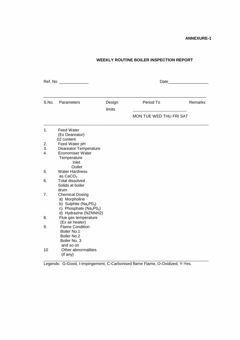
ANNEXURE-1
WEEKLY ROUTINE BOILER INSPECTION REPORT
Ref. No _____________ Date__________________
_________________________________________________________________________
S.No. Parameters Design Period To Remarks
limits ________________________
MON TUE WED THU FRI SAT
__________________________________________________________________________
1. Feed Water (Ex Deareator) 02 content 2. Feed Water pH 3. Deareator Temperature 4. Economiser Water Temperature Inlet Outlet 5. Water Hardness as CaCO3 6. Total dissolved Solids at boiler drum 7. Chemical Dosing a) Morpholine b) Sulphite (Na2P03) c) Phosphate (Na3P04) d) Hydrazine (NZNNH2) 8. Flue gas temperature (Ex air heater) 9. Flame Condition Boiler No.1 Boiler No.2 Boiler No. 3 and so on 10 Other abnormalities (if any) __________________________________________________________________________ Legends: G-Good, I-Impingement, C-Carbonised flame Flame, O-Oxidized, Y-Yes.

<< Back Home Next >>


