Backflow… What is it? Backflow? You may have heard of it, and you may understand some of what it involves. This booklet will help you to under- stand it better; exactly what it is, and how to prevent it. Backflow is the undesirable reversal of the flow of water or mixtures of water and other undesirable substances from any source (such as used water, industrial fluids, gasses, or any substance other than the intended potable water) into the distribution pipes of the potable water system. There are two types of backflow conditions: backpressure and backsiphonage. Backpressure: Occurs when the user system is at a higher pressure than the supply water systems allowing undesirable substances to be “pushed” back into the potable water system. Some causes are: booster pumps, potable water system connections for boilers, interconnection with other pip- ing systems operating at higher pressures, or higher elevations in user systems such as high- rise buildings. One specific example of this would be a steam heating sys- tem with the make-up water line piped directly into the boil- er. The higher pressure in the boiler could force the chemi- cally treated boiler water back through the make-up water line and into the potable water system. Backsiphonage: Occurs when negative or reduced pressure exists in the supply piping allowing undesirable sub- stances to be “drawn” into the potable water supply. Some causes are: undersized supply piping, sup- ply line breaks, reduced supply system pressure on the suc- tion side of an on-line booster pump, or sudden upstream high demand. An example of this is a child drinking milk with a straw. The child “sucks” on the straw and the milk flows up the straw and into the child’s mouth. What the child is actually doing is creating a subatmospheric pressure in his mouth and the atmospheric pressure (14.7psia at sea level) is pushing down on the surface of the milk and forcing the milk up the straw and into the child’s mouth. There is one other very impor- tant term that must be under- stood before we can proceed. The term is “Cross-Connection,” and it is defined as any actual or potential connec- tion between a potable water system and any other source or system through which it is possible to introduce into the potable system any used water, industrial fluid, gas, or other substance other than the intended potable water with which the system is supplied. By-pass arrangements, jumper connections, removable sec- tions, swivel or change-over devices and other permanent or temporary devices through which, or because of which, backflow can or may occur are considered to be cross- connections. City Water Boiler Make-Up Water Line 1
Transcript
Backflow…What is it?
Backflow? You may have heard of it, and you may understand some of what it involves. This booklet will help you to under-stand it better; exactly what it is, and how to prevent it.
Backflow is the undesirable reversal of the flow of water or mixtures of water and other undesirable substances from any source (such as used water, industrial fluids, gasses, or any substance other than theintended potable water) into the distribution pipes of the potable water system. There are two types of backflow conditions: backpressure and backsiphonage.
Backpressure: Occurs when the user system is at a higher pressure than the supply water systems allowing undesirable substances to be “pushed” back into the potable water system. Some causes are: booster pumps, potable water system connections for boilers, interconnection with other pip-ing systems operating at higher pressures, or higher elevations in user systems such as high-rise buildings.
One specific example of this would be a steam heating sys-tem with the make-up water line piped directly into the boil-er. The higher pressure in the boiler could force the chemi-cally treated boiler water back through the make-up water line and into the potable water system.
Backsiphonage: Occurs when negative or reduced pressure exists in the supply piping allowing undesirable sub-stances to be “drawn” into the potable water supply. Some causes are:
undersized supply piping, sup-ply line breaks, reduced supply system pressure on the suc-tion side of an on-line booster pump, or sudden upstream high demand. An example of this is a child drinking milk with a straw. The child “sucks” on the straw and the milk flows up the straw and into the child’s mouth. What the child is actually doing is creating a subatmospheric pressure in his mouth and the atmospheric pressure (14.7psia at sea level) is pushing down on the surface of the milk and forcing the milk up the straw and into the child’s mouth.
There is one other very impor-tant term that must be under-stood before we can proceed. The term is “Cross-Connection,” and it is defined as any actual or potential connec-tion between a potable water system and any other source or system through which it is possible to introduce into the potable system any used water, industrial fluid, gas, or other substance other than the intended potable water with which the system is supplied. By-pass arrangements, jumper connections, removable sec-tions, swivel or change-over devices and other permanent or temporary devices through which, or because of which, backflow can or may occur are considered to be cross- connections.
City Water
Boiler
Make-Up Water Line
1
Spray Hose in Sink This type of cross-connection is commonly found in the food industry and in janitor’s sinks. A hose has been connected to the faucet on the sink. When the faucet is left running, a loss in pressure of the supply main can siphon this used water back into the potable water system.
Submerged InletsIn many industrial installations that use chemically treated baths, the make-up water line runs directly into the tank. If there is backsiphonage, the toxic chemicals can be sucked back into the potable water system.
Hose BibsAt first glance, a hose bib seems innocuous, but it is the things people do with the hose that creates problems. In this example, a man is trying to blow a stoppage out in a sewer line, but with a sudden drop in line pressure, this contaminatedwater can be backsiphoned into the potable water system.
TypicalCross-Connections
Potable Water Line
Make-Up Water Line
HNO3 Solution
4
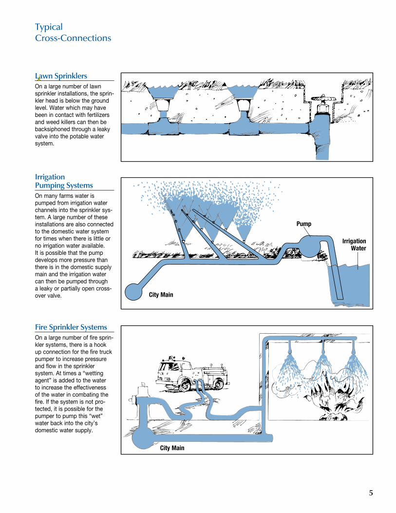
Lawn SprinklersOn a large number of lawn sprinkler installations, the sprin-kler head is below the ground level. Water which may have been in contact with fertilizers and weed killers can then be backsiphoned through a leaky valve into the potable water system.
Irrigation Pumping SystemsOn many farms water is pumped from irrigation water channels into the sprinkler sys-tem. A large number of these installations are also connected to the domestic water system for times when there is little or no irrigation water available. It is possible that the pump develops more pressure than there is in the domestic supply main and the irrigation water can then be pumped through a leaky or partially open cross-over valve.
Fire Sprinkler SystemsOn a large number of fire sprin-kler systems, there is a hook up connection for the fire truck pumper to increase pressure and flow in the sprinkler system. At times a “wetting agent” is added to the water to increase the effectiveness of the water in combating the fire. If the system is not pro-tected, it is possible for the pumper to pump this “wet” water back into the city’s domestic water supply.
TypicalCross-Connections
City Main
City Main
5
Pump
Irrigation Water
ericc
Cross-Out
ericc
Inserted Text
33
There are several different types of mechanical backflow prevention device. An alterna-tive to a mechanical device, is a physical separation, or air gap. The air gap is a physi-cal break in the system. The different types, of mechanical device, are used in different situations (if there is backpres-sure or backsiphonage) and for different degrees of hazard.
The degree of hazard is based on the fluid (or other substance)that may backflow into the supply piping system. The fluid may be toxic or nontoxic and could create a “non-health” or “health” hazard.
A non-health (non-toxic) haz-ard cross-connection is any point on a water supply system where a polluting substance may come in contact with potable water aesthetically affecting the taste, odor or appearance of the water, but not hazardous to health.
A health hazard (toxic) cross- connection is any point on a water supply system where a contaminating substance may come in contact with potable water creating an actual health hazard, causing sickness or death.
Double Check Valve Assembly (DC)The double check valve assembly (DC) is composed of two single, independently act-ing check valves. The unit also has two tightly closing, resilient seated, shutoff valves located at each end of the device and four test cocks for the testing of the check valves.
Reduced Pressure Principal Assembly (RP)Commonly referred to as an RP or RPP, this device con-sists of two independently acting check valves, together with an automatically operating pressure differential relief valve located between the two check valves. The first check valve reduces the supply pressure at a predetermined amount so that during normal flow, and at cessation of normal flow the pressure between the two check valves shall be lower than the supply pressure. If either check valve leaks, the relief valve will discharge to atmosphere. This will main-tain the pressure in the zone between the two check valves lower than the supply pressure. The unit also has two, resilient seated, shutoff valves (one upstream and one downstream of the checks) and properly located test cocks for field testing.
Pressure Vacuum Breaker (PVB)The pressure vacuum breaker (PVB) is a device that contains within a single body, a single loaded check valve and a loaded air opening valve which opens to admit air whenever the pressure within the body of the device approaches atmo-spheric. The device has two tight closing, resilient seated, shut-off valves, and it is fitted with test cocks, appropriately placed, for testing the device.
Dual Check Valve (DuC)The dual check (DuC) is a device which has two single, independent acting check valves in series. It does not have any testcocks and is gen-erally not field tested.
Dual Check with Atmospheric Port (DCAP)This device has two indepen-dent acting check valves with a relief valve located between the checks. The device is not testable and should only be used for lower degrees of hazard.
Atmospheric Vacuum Breaker (AVB)An atmospheric vacuum break-er (AVB) is a device which has a moving element inside, which during flow prevents water from spilling from the device and during cessation of flow, drops down to provide a vent opening. This device should not remain under pressure for long durations, and it cannot have any shutoff valve down-stream of it.
Air GapAn air gap is a physical separa-tion between the free flowing discharge end of a potable pipe line and an open or non-pressure receiving vessel. To have an acceptable air gap, the end of the discharge pipe has to be at least twice the diameter of the pipe above the topmost rim of the receiving vessel, but in no case can this distance be less than one inch.
This may seem to be the sim-plest, most effective and least expensive type of protection. However, the chance for future cross-connections, the cost of additional pumps to pressurize the system often makes this an expensive protection system.
Spill-Resistant Vacuum Breaker (SVB) The valve shall consist of a one-piece modular check valve force-loaded closed and an air inlet valve forced loaded open to atmosphere, positioned downstream of the check valve, and located between two (2) tightly closing shut-off valves and two (2) test cocks.
Backflow PreventionDevices
6
This figure shows an RP device during a backsiphonage con-dition. If you will notice, both checks are closed tight and the pressure differential relief valve is discharging to atmo-sphere. This is due to the fact that the relief valve is designed to maintain a lower pressure in the zone between the two check valves than the supply pressure.
In this figure of an RP device, there is a backpressure con-dition. The second check is fouled with a piece of pipe scale which permits the higher pressure to flow back into the zone. Here the relief valve discharges the water to atmo-sphere maintaining the pres-sure in the zone lower than the supply pressure.
In this view of a pressure vacuum breaker, a backsiphon-age condition has caused the check to close against its seat and the air-inlet has opened so that the pressure in the body of the device is atmospheric. If the check was fouled by some foreign material, only air would be pulled back into the domes-tic supply system instead of the non-potable water downstream of the device.
In this view of a double check valve, there is backpressure from a source downstream which has caused the second check to close tightly against this reverse pressure. The first check has closed tightly by itself, thus giving two barriers against the backflow condition.
How Backflow PreventionDevices Work
In this picture of an atmospheric vacuum breaker, a backsiphon-age condition exists. This condi-tion has caused the check-float to drop away from the air-inlet and seat on the check seat, which prevents the non-potable water from being backsiphoned. If the check-float did not seat properly, again only air would be sucked back into the domes-tic water system.
97psi
100psi 105psi
100psi 105psi
80psi 92psi
7
Device Selection Installation
Having a device on the con-nection is not enough, the device MUST be installed cor-rectly. The following details and illustrations will help you in the proper installation of the devices.
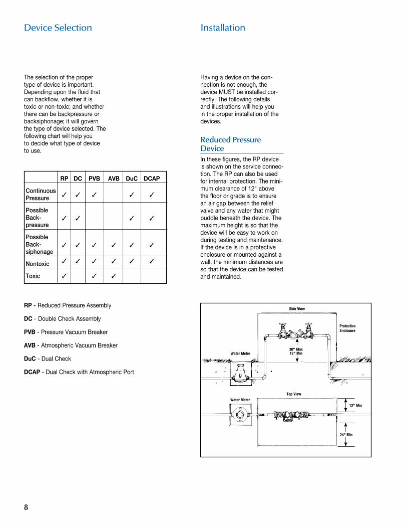
Reduced Pressure Device In these figures, the RP device is shown on the service connec-tion. The RP can also be used for internal protection. The mini-mum clearance of 12" above the floor or grade is to ensure an air gap between the relief valve and any water that might puddle beneath the device. The maximum height is so that the device will be easy to work on during testing and maintenance. If the device is in a protective enclosure or mounted against a wall, the minimum distances are so that the device can be tested and maintained.
RP - Reduced Pressure Assembly
DC - Double Check Assembly
PVB - Pressure Vacuum Breaker
AVB - Atmospheric Vacuum Breaker
DuC - Dual Check
DCAP - Dual Check with Atmospheric Port
The selection of the proper type of device is important. Depending upon the fluid that can backflow, whether it is toxic or non-toxic; and whether there can be backpressure or backsiphonage; it will govern the type of device selected. The following chart will help you to decide what type of device to use.
Side View
Protective Enclosure
30" Max 12" Min
12" Min
Water Meter
Water MeterTop View
24" Min
RP DC PVB AVB DuC DCAP
Continuous Pressure ✓ ✓ ✓ ✓ ✓
Possible Back- pressure
✓ ✓ ✓ ✓
Possible Back- siphonage
✓ ✓ ✓ ✓ ✓ ✓
Nontoxic ✓ ✓ ✓ ✓ ✓ ✓
Toxic ✓ ✓ ✓
8
Installation Testing
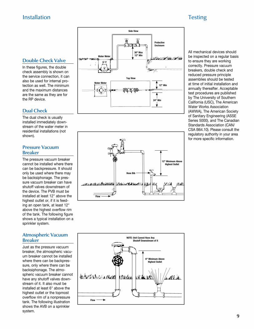
Double Check ValveIn these figures, the double check assembly is shown on the service connection, it can also be used for internal pro-tection as well. The minimum and the maximum distances are the same as they are for the RP device.
Dual CheckThe dual check is usually installed immediately down-stream of the water meter in residential installations (not shown).
Pressure Vacuum BreakerThe pressure vacuum breaker cannot be installed where there can be backpressure. It should only be used where there may be backsiphonage. The pres-sure vacuum breaker can have shutoff valves downstream of the device. The PVB must be installed at least 12" above the highest outlet or, if it is feed-ing an open tank, at least 12" above the highest overflow rim of the tank. The following figure shows a typical installation on a sprinkler system.
Atmospheric Vacuum BreakerJust as the pressure vacuum breaker, the atmospheric vacu-um breaker cannot be installed where there can be backpres-sure, only where there can be backsiphonage. The atmo-spheric vacuum breaker cannot have any shutoff valves down-stream of it. It also must be installed at least 6" above the highest outlet or the topmost overflow rim of a nonpressure tank. The following illustration shows the AVB on a sprinkler system.
All mechanical devices should be inspected on a regular basis to ensure they are working correctly. Pressure vacuum breakers, double check and reduced pressure principle assemblies should be tested at time of initial installation and annually thereafter. Acceptable test procedures are published by The University of Southern California (USC), The American Water Works Association (AWWA), The American Society of Sanitary Engineering (ASSE Series 5000), and The Canadian Standards Association (CAN/CSA B64.10). Please consult the regulatory authority in your area for more specific information.
Side View
Protective Enclosure
30" Max 12" Min
12" Min
Water Meter
Water Meter
Top View
Flow
Hose Bib
24" Min
12" Minimum Above Highest Outlet
NOTE: Unit Cannot Have Any Shutoff Downstream of it