Background Report Reference AP-42 Section Number: 9.12.1 Background Chapter: 4 Reference Number: 30 Title: i Filler Room Vent Emissions Reduction, Project 3VT, Results and Final Report Coors Brewing Company Coors Brewing Company December 1993
Transcript
Background Report Reference
AP-42 Section Number: 9.12.1
Background Chapter: 4
Reference Number: 30
Title:
i
Filler Room Vent Emissions Reduction, Project 3VT, Results and Final Report
Coors Brewing Company
Coors Brewing Company
December 1993
EPA
Text Box
Note: This is a reference cited in AP 42, Compilation of Air Pollutant Emission Factors, Volume I Stationary Point and Area Sources. AP42 is located on the EPA web site at www.epa.gov/ttn/chief/ap42/ The file name refers to the reference number, the AP42 chapter and section. The file name "ref02_c01s02.pdf" would mean the reference is from AP42 chapter 1 section 2. The reference may be from a previous version of the section and no longer cited. The primary source should always be checked.
A brewing facility evaluated the feasibility of using process changes to reduce emissions of volatile organic compounds (VOC) from the filling operation. The facility implemented and tested the effects of filler room air flow controls, and fill- level controls and drip troughs to control beer spillage on can filler ethanol emissions. Evaluation of bottle filler changes included filler room air flow controls, and drip troughs.
The objective of the air flow control test was to determine whether a reduction in air flow would result in a reduction in the ethanol emission rate, and, if so, would the reduction be directly proportional to the reduction in air flow; Testing performed indicated that the use of air flow controls reduce VOC e&ssions by reducing the air velocity in the filler room. The use of air flow controls resulted in a reduction of VOC emissions of 24%.
The fill-level controls were installed with the purpose of controlling the amount of beer that is spilled when filling. The troughs were designed to collect the spilled beer and pipe it directly to the floor drains without letting the beer spread out on the floor, therefore, decreasing the surface area of the beer and reducing VOC emissions. Neither the use of fill-level control, in the form of adjustable ball cages and fill valve monitors, or the use of drip troughs resulted in any significant change in ethanol emissions. Tests were also performed to evaluate the effect of flushing the floor drains with water. These tests also revealed little effect on ethanol emissions.
*Confidential business information has been removed Gom this report. If you have any questions regarding this report please contact:
Ethanol is a volatile organic compound (VOC) and is subject to control and regulation by the Environmental Protection Agency (EPA) and the Colorado Department of Health (CDH) . The purpose of this project was to assess the possibility of using process changes to reduce the ethanol emissions from the fillers rather than adding end-of-pipe pollution control devices.
This project implemented and tested the effects of prototype process changes on ethanol emissions on can and bottle fillers at the Golden packaging facility. The test beds chosen were 9 can filler and 3 bottle filler.
The can filler modifications tested were fill level control, filler room air flow control, and drip troughs.
The bottle filler modifications examined were filler room air flow control and drip troughs.
11. CONCLUSIONS.
Air flow control reduced ethanol emissions by reducing air velocity in the filler room. The amount of reduction from air flow control was 2 4 % .
The effects of fill level control (adjustable ball cages and fill valve monitor) and drip troughs did not reveal any significant changes in ethanol emissions.
Air flow control reduced ethanol emissions in the bottle filler room by 21%. Drip troughs could not be implemented in the bottle filler room. However, based on the results of drip troughs in the can filler, reductions were not anticipated. Further work needs to be done on bottle fillers in identifying the source of ethanol emissions. One
Note: All charts and graphs are located in Appendix A.
possible technique would be washing the bottles with chilled water when the bottles are still contained in the shroud.
111. BACKGROUND.
A. 9 FILLER MODIFICATIONS.
Nine filler consists of one 72-valve Cemco filler with an Angelus 12OL closer. The filler room has stainless steel walls and floor with no gap between the wall and the floor.
1. Fill Level Control.
Adjustable ball cages were installed on all 72 fill valves. The adjustable ball cages were adjusted to provide an average of 5.5 gms overfill as opposed to 1.2 gms.
A Filler Valve Monitor System (FILTEC Model FT- 100) was installed to provide information on fill levels for each fill valve. In addition the hard copy output port of the fill valve monitor system was connected to a printer in order to provide a printout of the shift summaries.
2. Air Flow Control.
Air flow automation was provided and installed by Landis & Gyr Powers, Inc. There were 2 systems installed under this project. One system for the 9 can filler room and another for the 3 bottle filler room. Each system is physically separate and functions independently of the other. Both systems are tied into the Powers Network for the
Note: All charts and graphs are located in Appendix A
Brewery and are accessed through modems or direct connections.
Each system controls the air flow for its associated filler room. The objective was to minimize air flow while maintaining a positive pressure within the room and at the same time ensure that the CO, level did not exceed a preset threshold. These objectives were accomplished in the following manner:
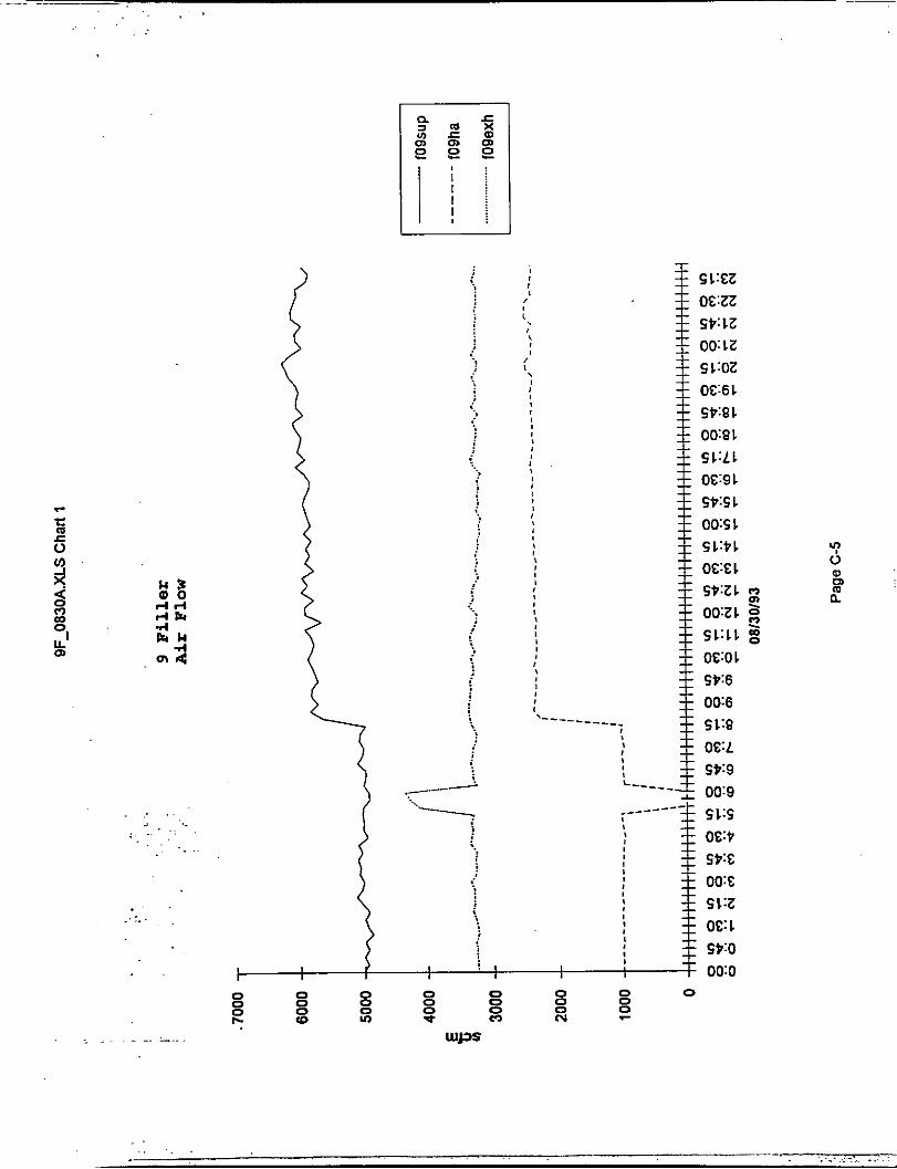
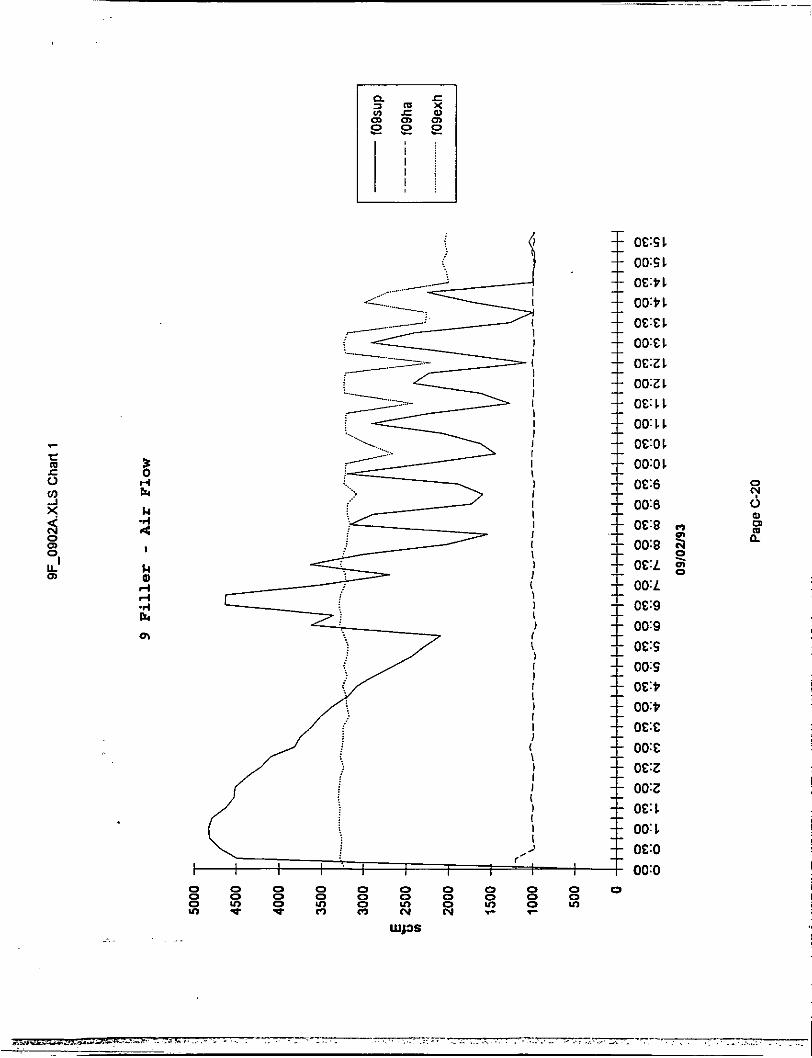
a. Filler Shroud Air (Hepa/Sterile air). - The air flow to the filler shroud was maintained at a constant velocity. Control dampers and sensors were installed to accomplish this goal. The shroud air supply was set to 1000 scfm per filler.
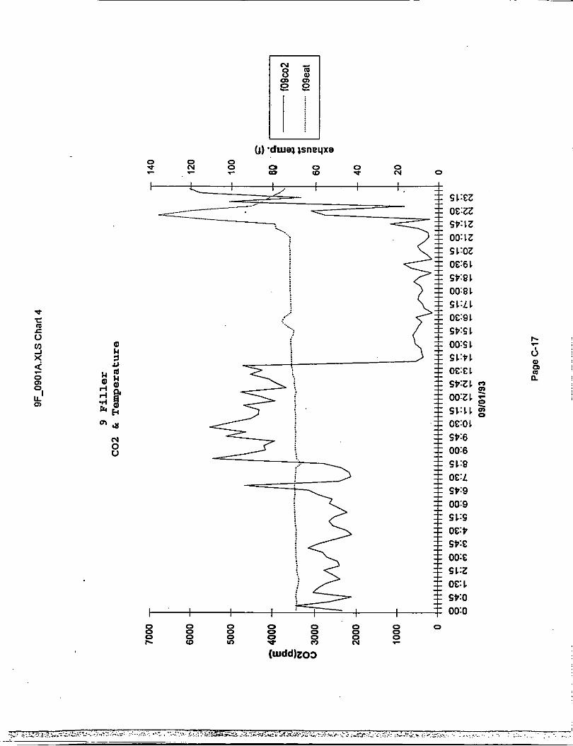
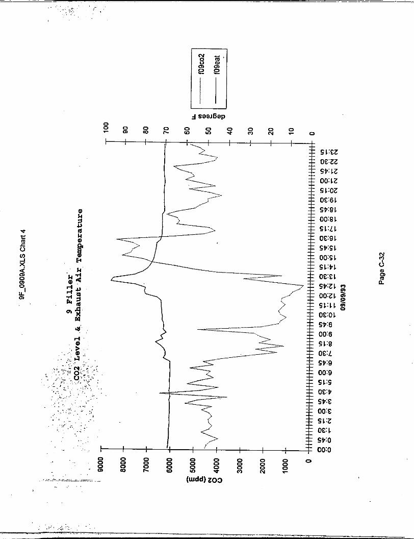
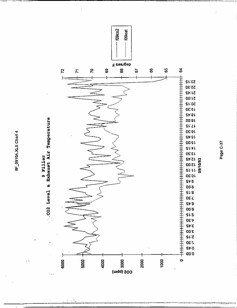
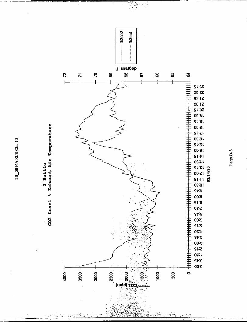
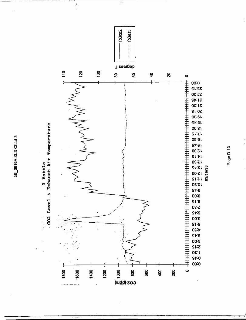
b. Room Supply Air (Filtered). - The air supply to the room was controlled so that the CO, level in the room did not exceed a preset value. The air supply to the room was also
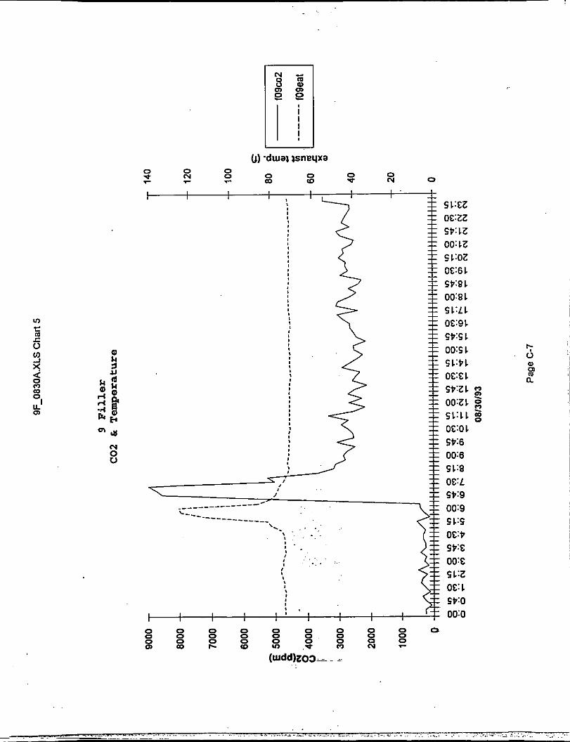
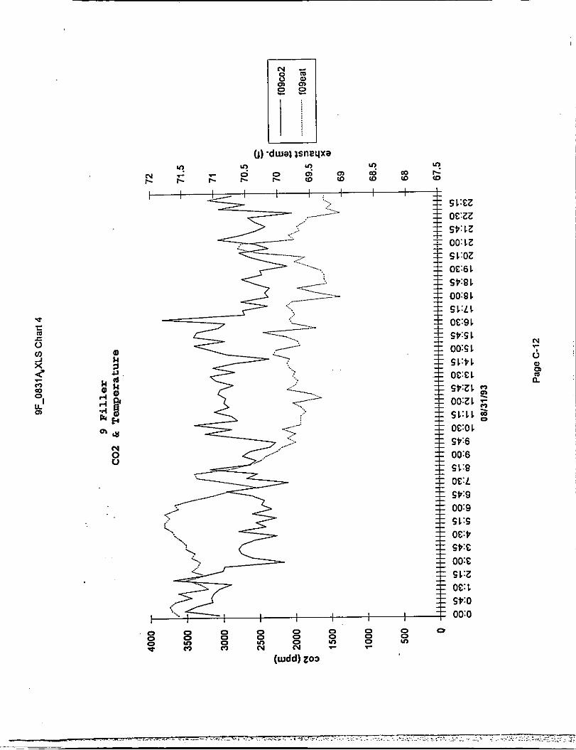
exceeded a preset value. The set point for room CO, level was 4500 ppm. The temperature threshold was 72O F.
. increased when exhaust.air temperature
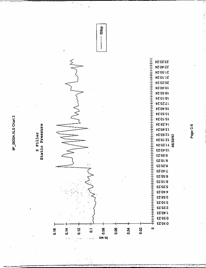
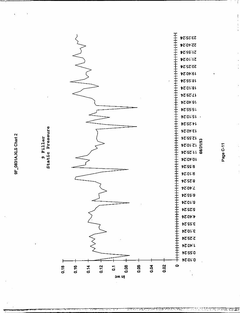
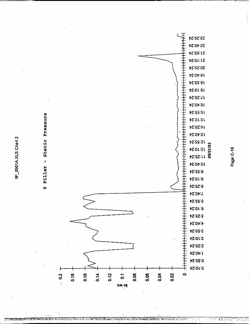
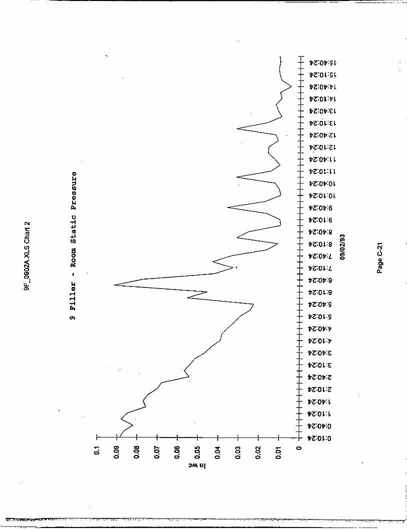
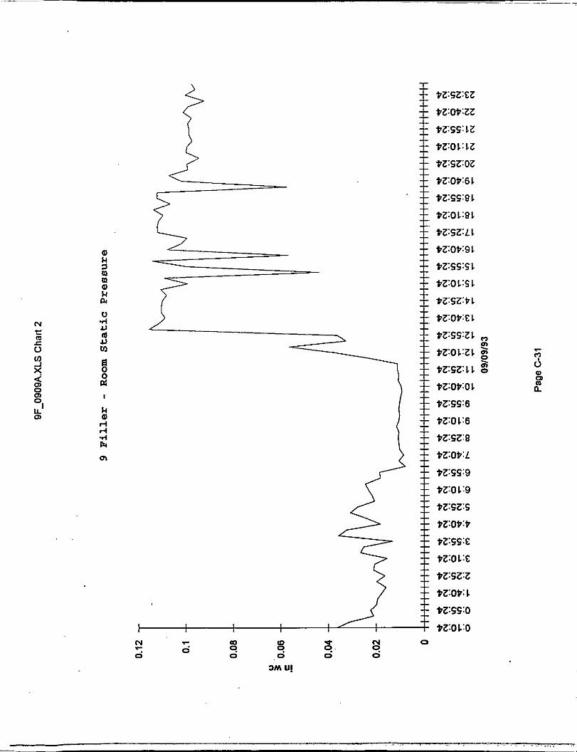
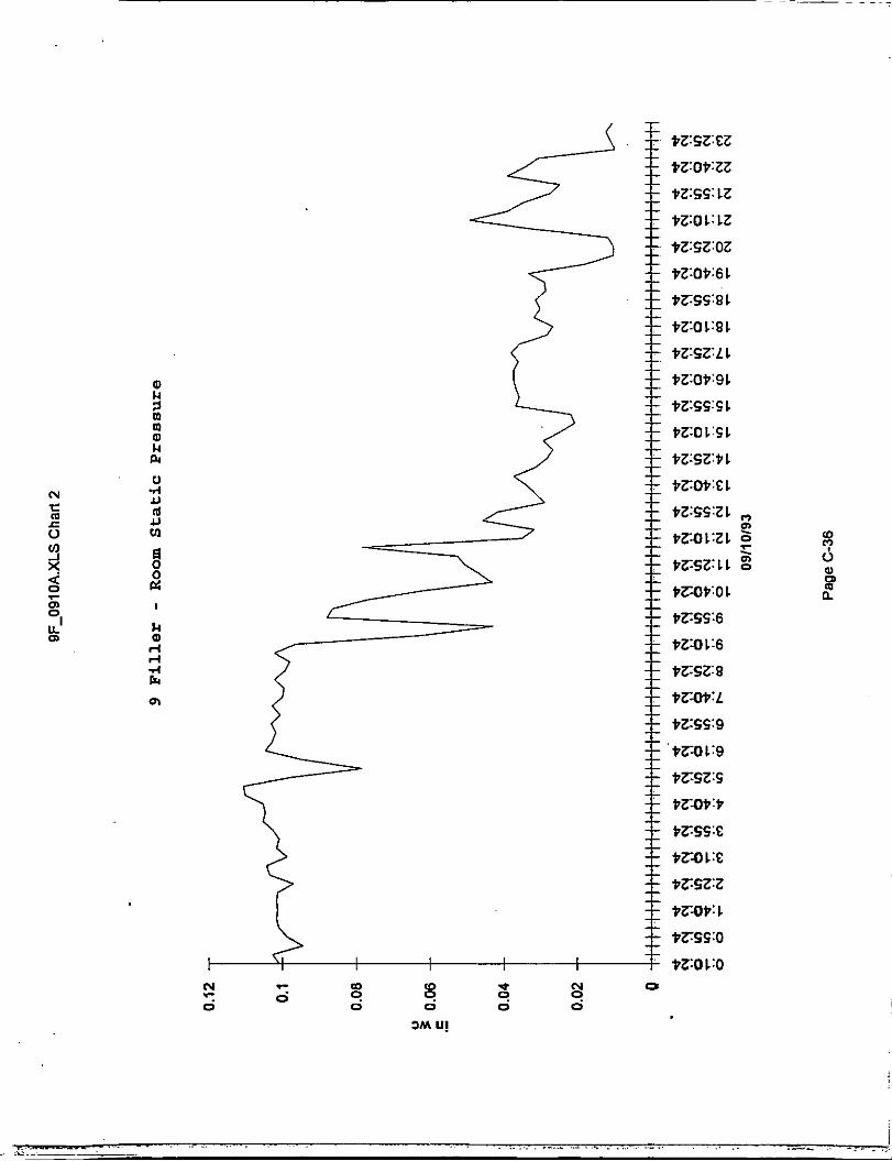
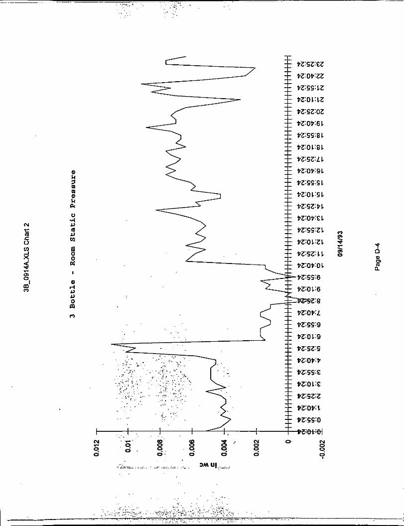
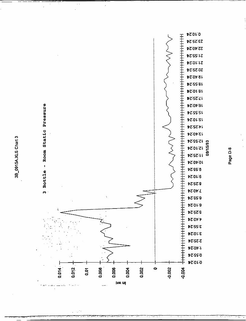
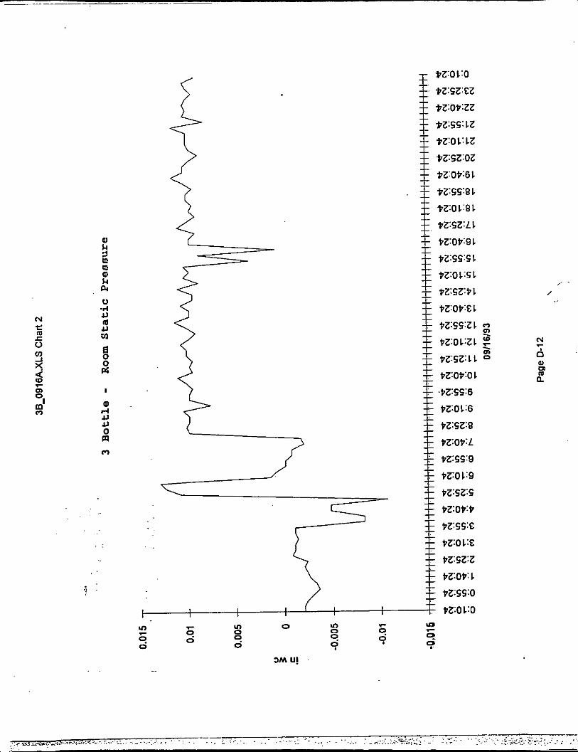
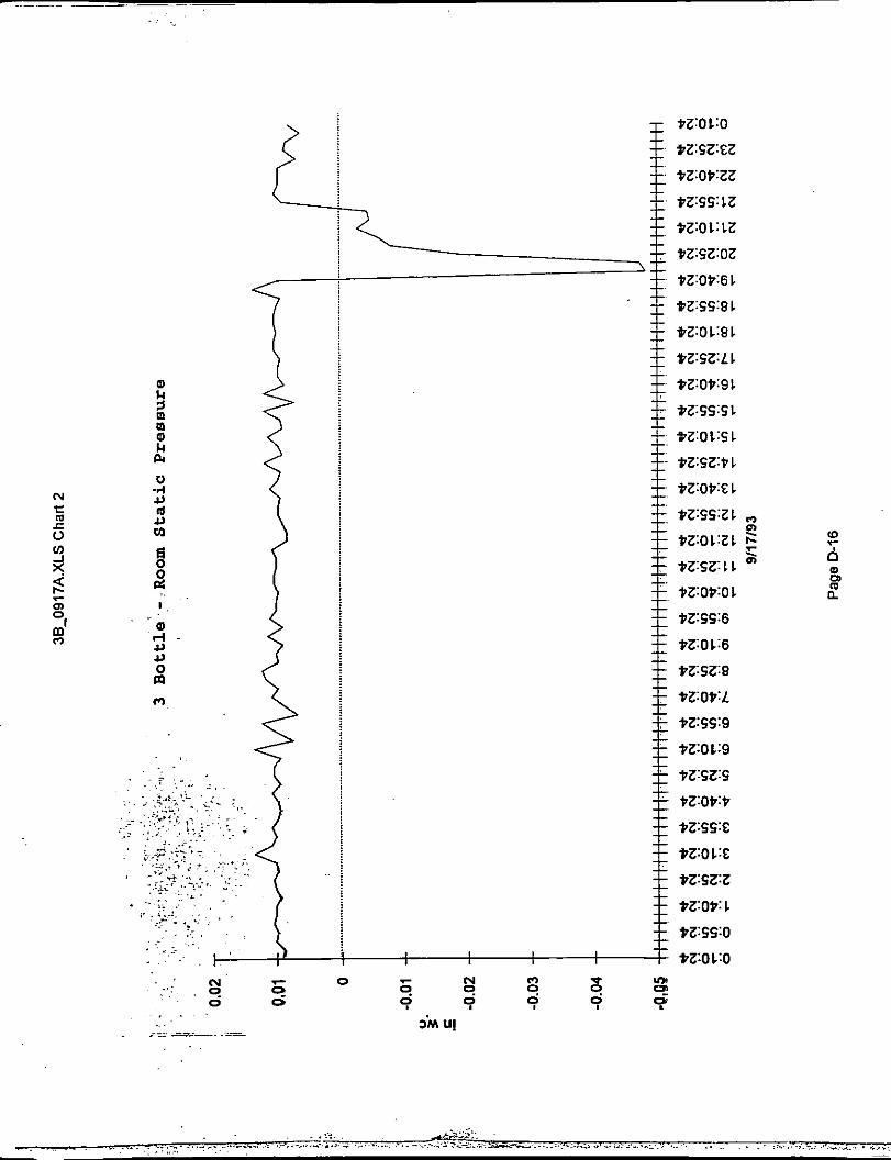
c. CO, Exhaust Air Flow. - The air flow out of the room through the C02 exhaust duct was controlled so that a positive pressure in the room was maintained. The set point for room static pressure was 0.01 inches water column that translated into a fugitive escape velocity of approximately 500 fpm.
d. Monitoring and Control. - A CRT and printer were installed in the offices of Continuous Improvement to monitor and control both
Note: All charts and graphs are located in Appendix A.
3.
systems. This CRT also accessed all systems on the network. In addition, Facilities Maintenance maintained a host computer system that monitored and controlled all Powers Automation Systems on the brewery network.
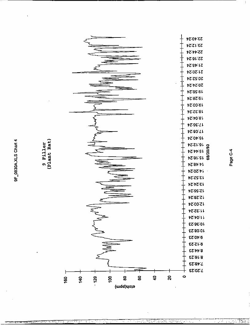
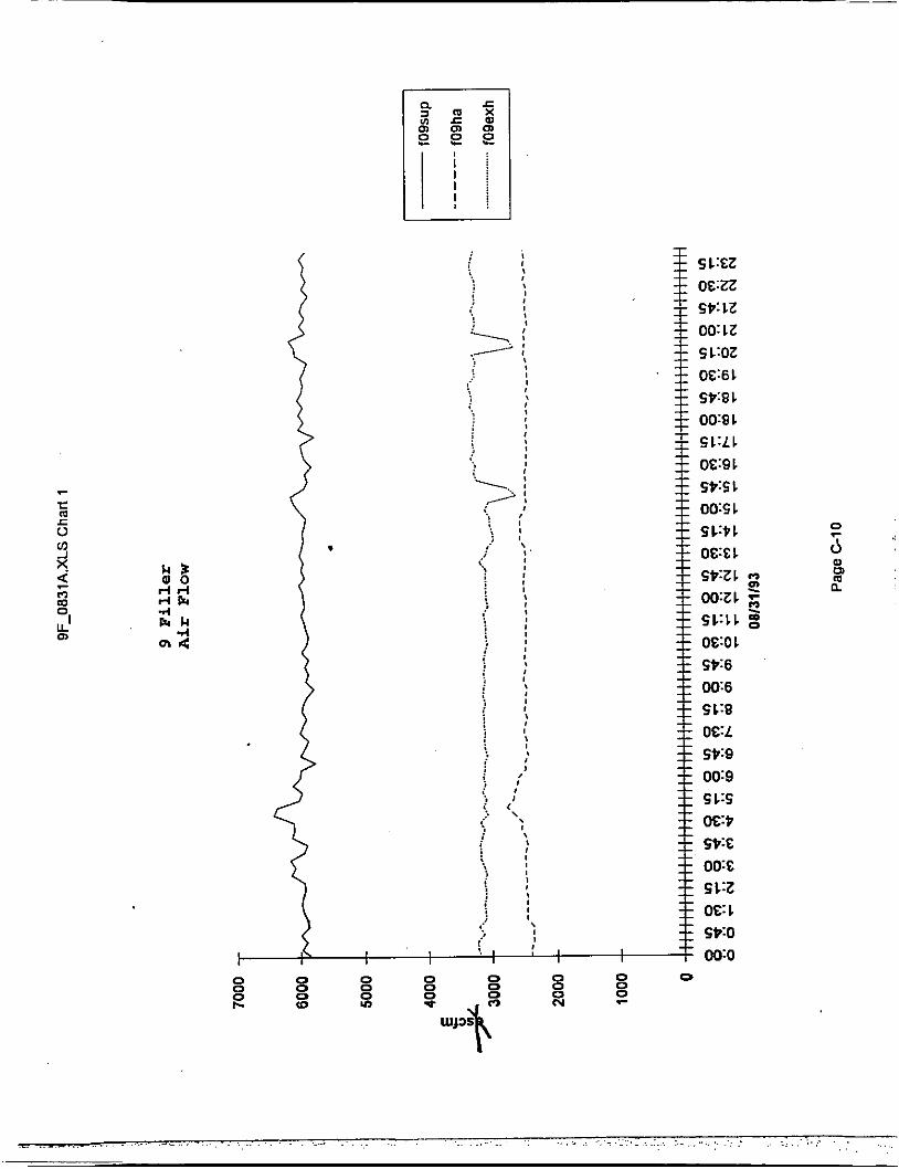
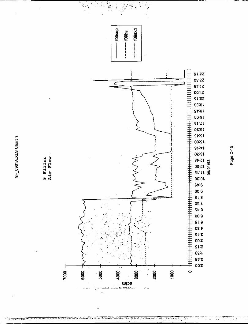
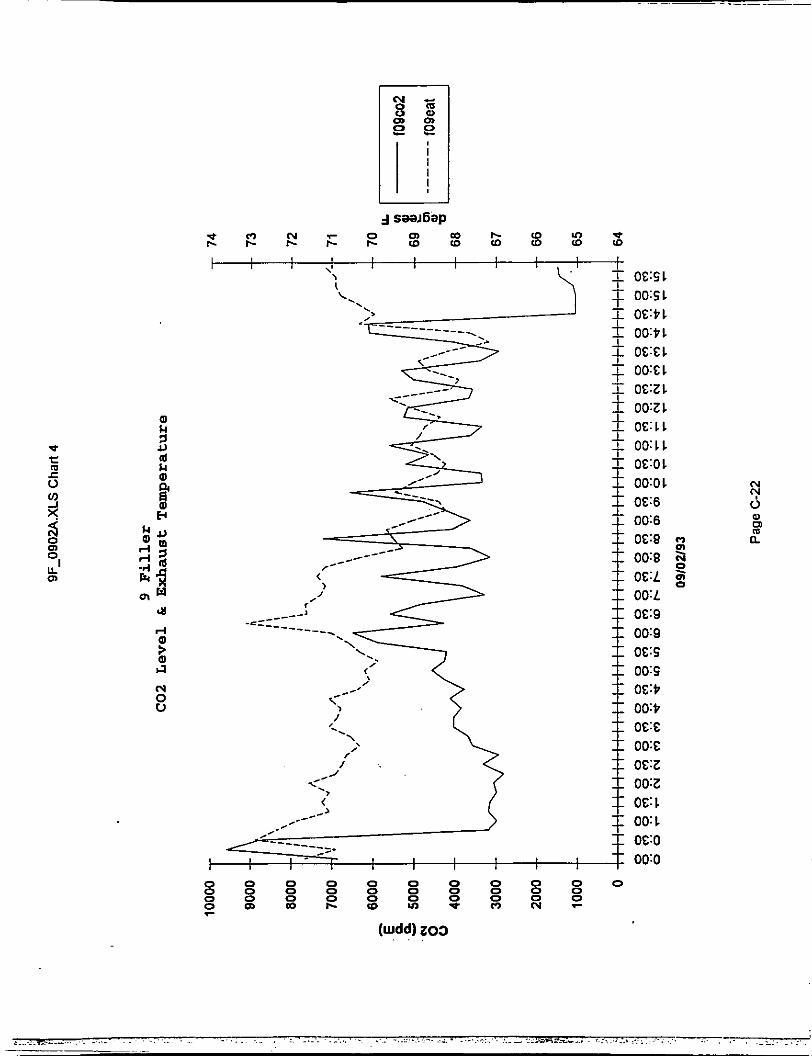
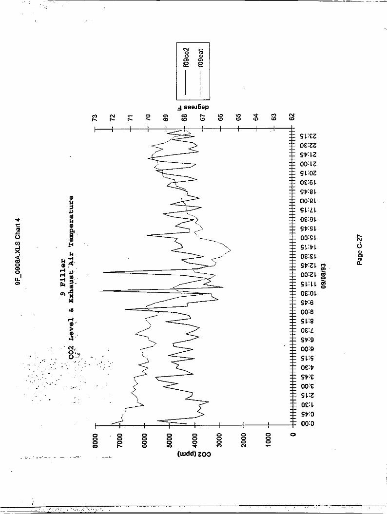
A fortuitous ability of the automation system was its ability to trend data. This ability provided a data logging capability when VOC testing was being performed. Types of data logged were supply air flow, shroud air flow, C02 exhaust duct air flow, room static pressure, room CO, level, and exhaust duct air temperature. The ethanol data from the B&W Plant Rat instrument installed in 9 filler was also logged.
The minimum room air supply in 9 filler was set to 1000 scfm in order to supply adequate air flow to the operator. This resulted in a static pressure that was higher than the desired 0.01 inches water column.
D r i p Troughs.
Drip troughs were installed on the 4 sides of the closer and under the no can/no fill station on the filler. These troughs were designed to catch spilled beer and pipe it directly to the floor drains without letting the beer spread out on the floor.
B. 3 BOTTLE FILLER MODIFICATIONS.
Three ( 3 ) Bottle consists of two 72-valve Cemco fillers in one room. The room consists of stainless steel walls with a concrete floor. There are no gaps between the walls and the floor.
Note: All charts and graphs are located in Appendix A.
1. Air Flow Control.
An air flow control system described above was installed to control the air flow in the 3 bottle filler room. See 5 III.A.3 above for details.
2 . Drip Troughs.
There was not a practical way of installing drip troughs on a bottle filler. The installation of drip troughs would needlessly interfere with operations, maintenance and sterilization.
C. FLOW METERS.
Rosemont magnetic flow meters were installed on the beer supply lines for 9 filler and 3 bottle ( 2 meters, 1 per filler). A resettable readout for each meter was installed that provides total beer in gallons entering each filler. Various studies performed by the Continuous Improvement Department reveal that the accuracy of .the meters is.approximately 5%. A,.= Flaw Meter Accuracy Task Force addressed the accuracy problems. Until better meter accuracy is obtained, the technique of relating VOC emissions as a function of beer into a filler is not viable.
D. VOC MONITORING.
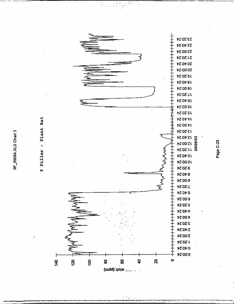
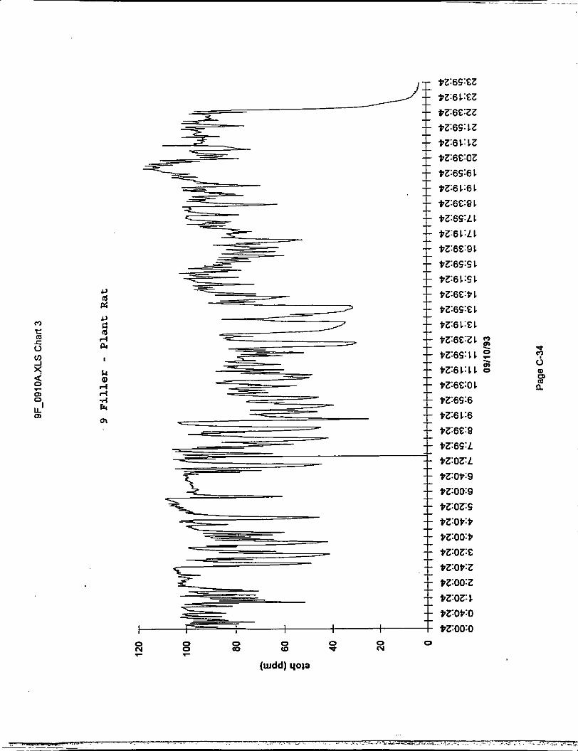
A n alternate method of measuring ethanol concentration in air (other than FID) was investigated.. A B&W Technologies Plant Rat Model IS-PRB-1 instrument was installed on 9 filler to test its capabilities of .detecting ethanol. The Plant Rat uses fuel cell technol6gy that originally was developed for carbon monoxide and modified to work with ethanol. In fact,
Note: All charts and graphs are located in Appendix A.
the sensor is calibrated using carbon monoxide gas and reads directly in ppm ethanol.
The sensor was installed in the CO, exhaust duct with the display located on the 1st floor near the filler room. The 4-20 ma output of the instrument was routed to the Powers automation system for data logging.
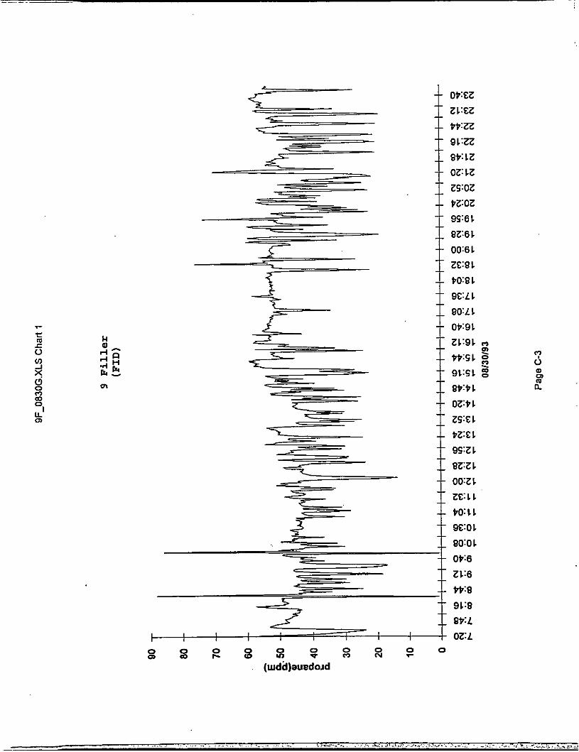
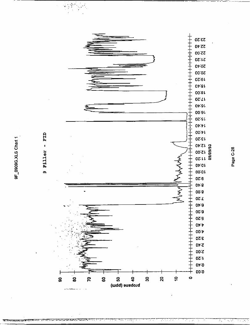
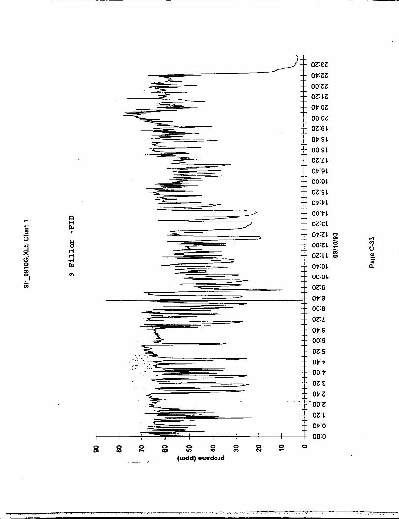
The ability of the B&W Plant Rat to detect and measure the presence of ethanol is excellent. Comparisons were made to Clean Air Engineering's (CAE) flame ionization detector (FID) which sampled the exhaust duct near the Plant Rat. As can be seen from the 2 sets of data from August 31, 1993 (FID and Plant Rat, presented in Appendix B, pages 1 & 2 ) , there was excellent correlation between the two instruments. There is a scale difference due to the fact that the FID is calibrated using propane and the Plant Rat is calibrated using carbon monoxide. That scale factor difference is 2.18. The chart shown on page 3 of Appendix B shows the FID plotted against the Plant Rat. The FID measurements resolves 97% of the Plant Rat variations.
.
IV. ANALYSIS.
A. SAMPLE CALCULATIONS.
1. Emission Rate.
The emission rate is the amount of ethanol released to the atmosphere for every hour of filler operation.
The emission rate in lbs/hr ethanol was calculated as follows:
Note: All charts and graphs are located in Appendix A
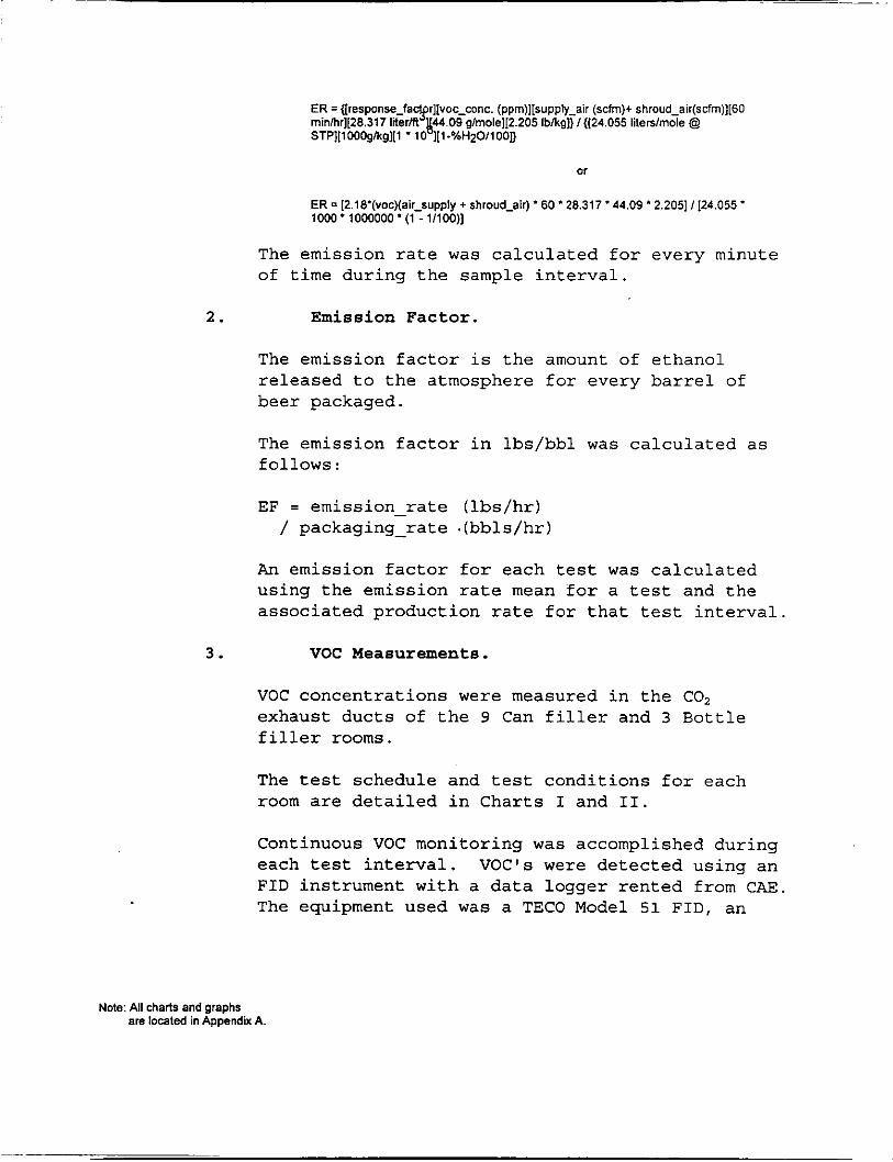
The emission rate was calculated for every minute of time during the sample interval.
2 . Emission Factor.
The emission factor is the amount of ethanol released to the atmosphere for every barrel of beer packaged.
The emission factor in lbs/bbl was calculated as follows:
EF = emission rate (lbs/hr) / packaging-rate - .(bbls/hr)
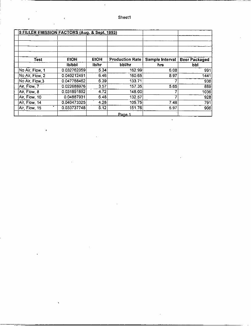
An emission factor for each test was calculated using the emission rate mean for a test and the associated production rate for that test interval.
3 . VOC Measurements.
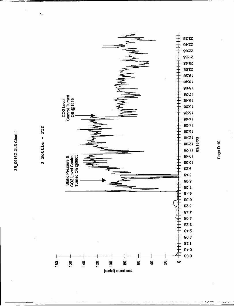
VOC concentrations were measured in the C02 exhaust ducts of the 9 Can filler and 3 Bottle filler rooms.
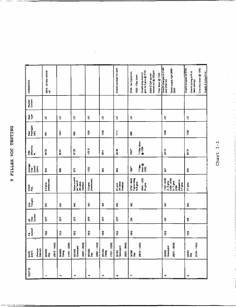
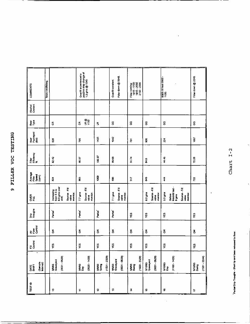
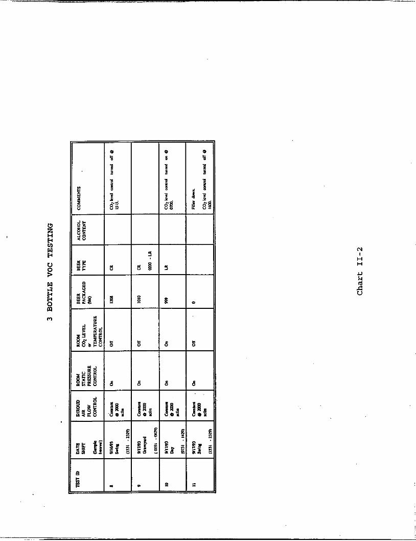
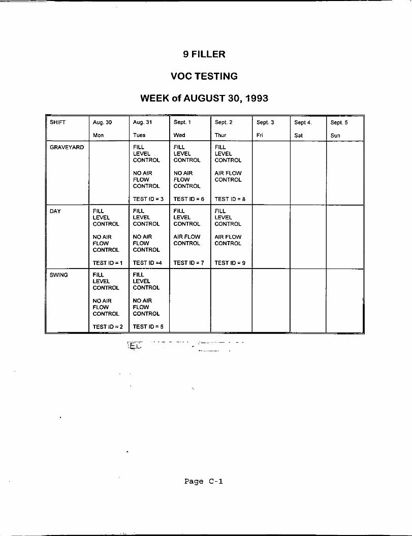
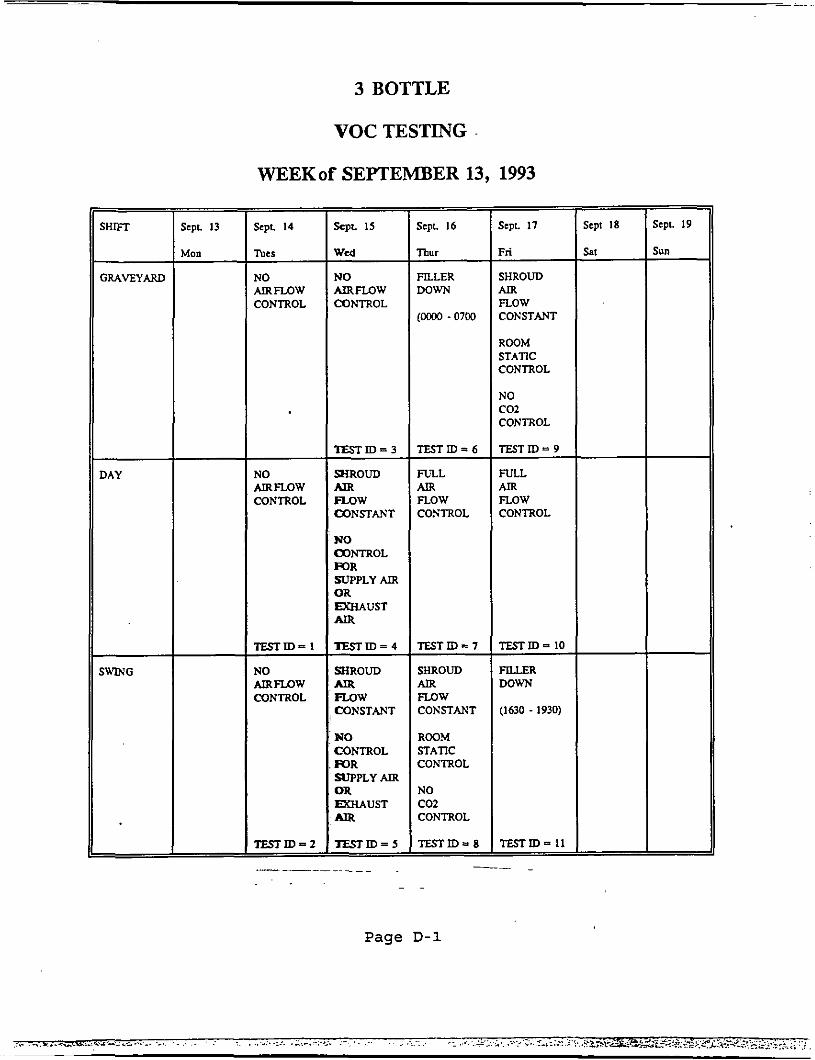
The test schedule and test conditions for each room are detailed in Charts I and 11.
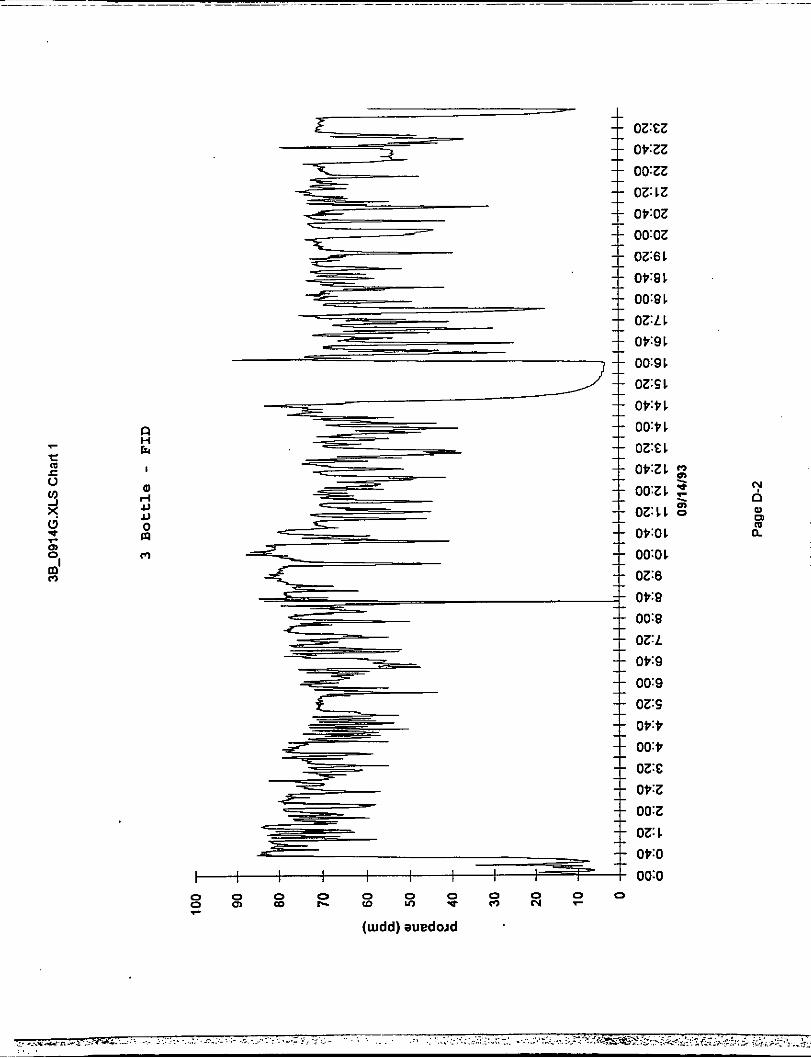
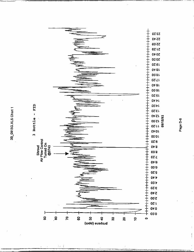
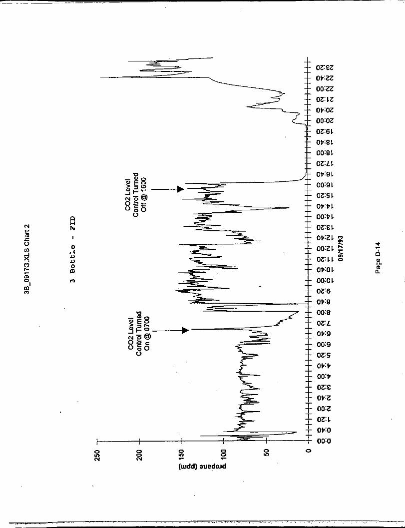
Continuous VOC monitoring was accomplished during each test interval. VOC's were detected using an FID instrument with a data logger rented from CAE. The equipment used was a TECO Model 51 FID, an
Note: All charts and graphs are located in Appendix A.
Odessa DSM 3260 data logger, a Yokogawa 3057-2 dual channel strip chart recorder, and a laptop computer for control and data disk creation. F I D was calibrated daily using a calibration gas of 86 ppm propane in nitrogen.
The
4 . Air Flow.
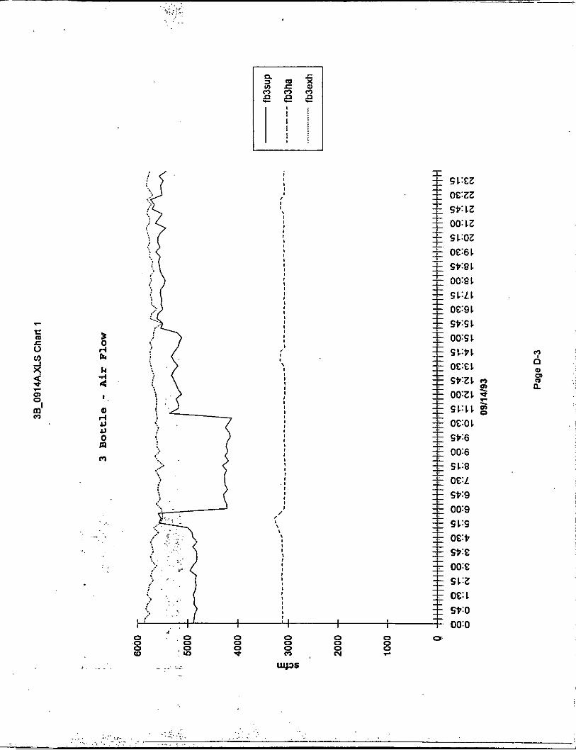
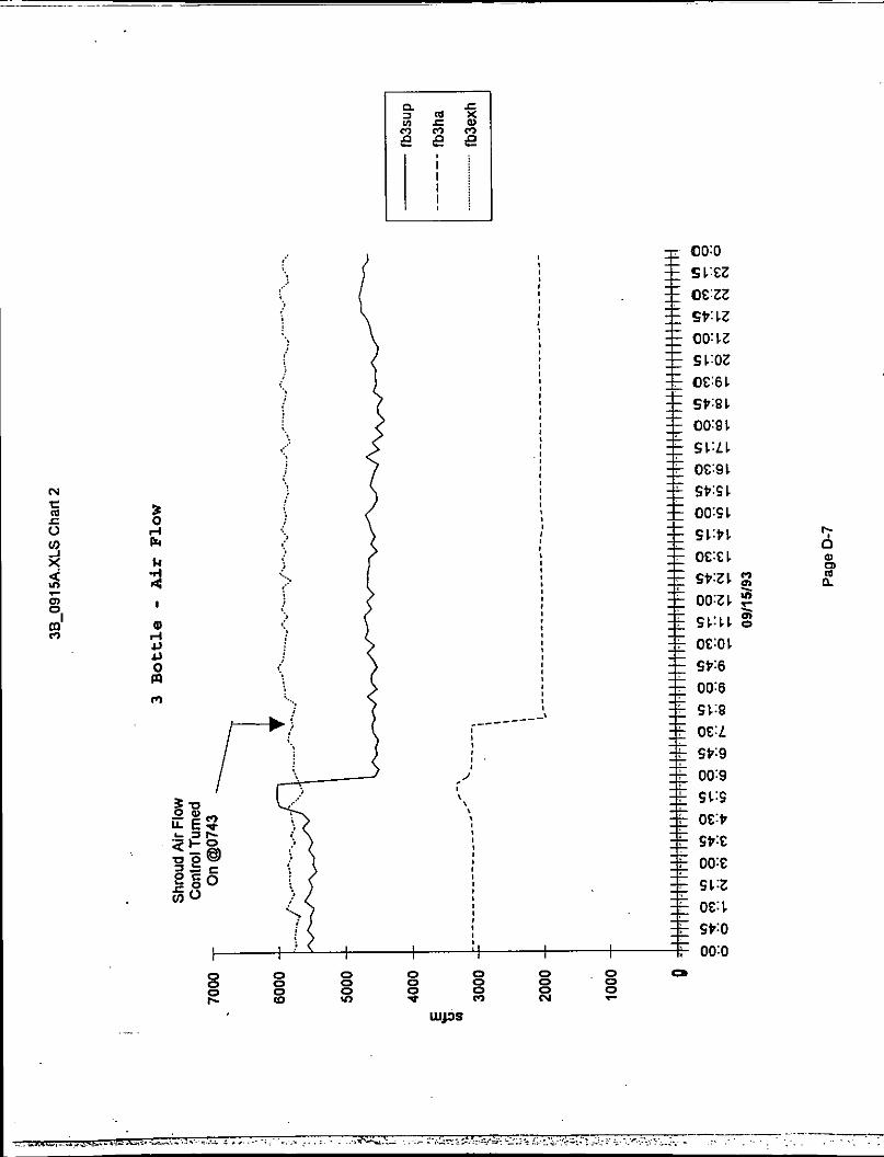
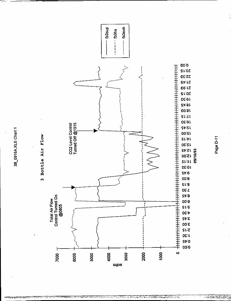
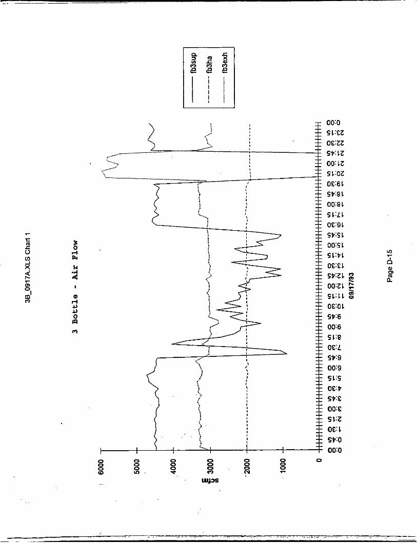
Air flow data was collected using the data logging capability of the Powers Air Flow Automation System. Air flow data collected were from the shroud air supply, room air supply and C02 exhaust duct. The total air supplied to the room (shroud air plus supply air) were used in the emission calculations. The total air supplied to the filler room was used in the calculations in order to include air exhausted through the C02 exhaust duct plus fugitive emissions to the packaging building. This technique assumes that the VOC concentration at all room exits is the same as measured in the C02 exhaust duct.
The Air Flow Automation System sensors were calibrated by comparing against a manual transverse of the ducts involved. The 3 Bottle shroud air sensor measurements were reduced by 712 scfm as a result of these calibrations.
B. 9 FILLER.
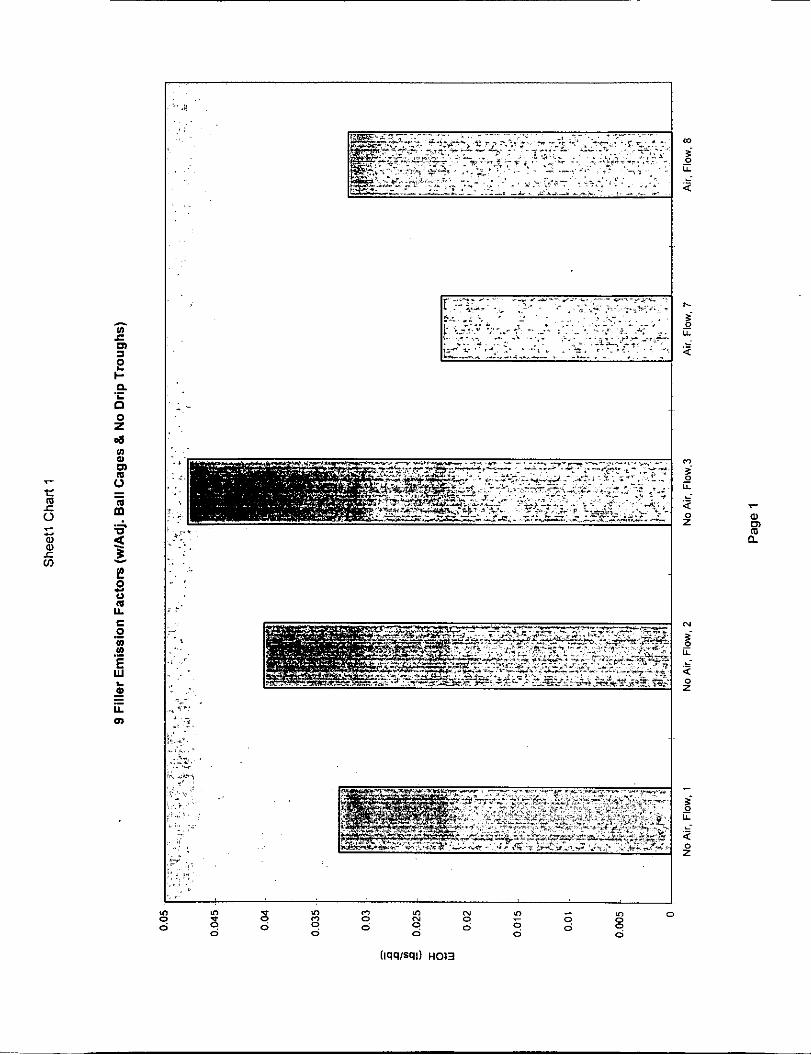
A statistical box plot of the emission rates (lbs/hr) for all of the 9 Filler VOC tests are presented in Graph 111. Graph IV presents the emission factors (lbs/bbl) for the same set of tests.
The raw data from all the tests are contained in Appendix C.
Note: All charts and graphs are located in Appendix A.
1.
2 .
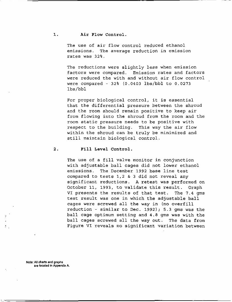
Air Flow Control.
The use of air flow control reduced ethanol emissions. The average reduction in emission rates was 32%.
The reductions were slightly less when emission factors were compared. Emission rates and factors were reduced the with and without air flow control were compared - 32% (0.0403 lbs/bbl to 0.0273 lbs/bbl
For proper biological control, it is essential that the differential pressure between the shroud and the room should remain positive to keep air from flowing into the shroud from the room and the room static pressure needs to be positive with respect to the building. This way the air flow within the shroud can be truly be minimized and still maintain biological control.
Fill Level Cont ro l .
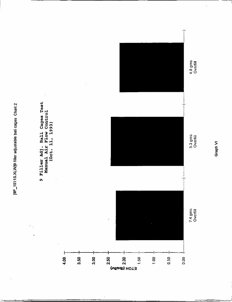
The use of a fill valve monitor in conjunction with adjustable ball cages did not lower ethanol emissions. The December 1992 base line test compared to tests 1,2 & 3 did not reveal any significant reductions. A retest was performed on October 11, 1993, to validate this result. Graph VI presents the results of that test. The 7.4 gms test result was one in which the adjustable ball cages were screwed all the way in (no overfill reduction - similar to Dec. 1992); 5.3 gms was the ball cage optimum setting and 4 . 8 gms was with the ball cages screwed all the way out. The data from Figure VI reveals no significant variation between
Note: All charls and graphs are located in Appendix A
3 .
C .
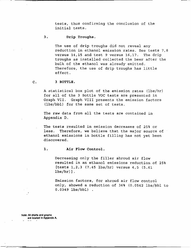
tests, thus confirming the conclusion of the initial tests.
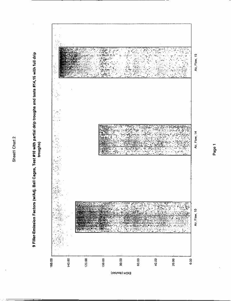
Drip Troughs.
The use of drip troughs did not reveal any reduction in ethanol emission rates. See tests ? , 8 versus 14,15 and test 9 versus 16,17. The drip troughs as installed collected the beer after the bulk of the ethanol was already emitted. Therefore, the use of drip troughs has little effect.
3 BOTTLE.
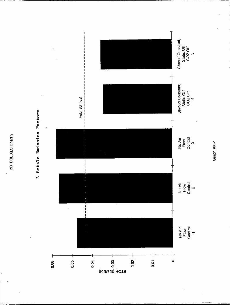
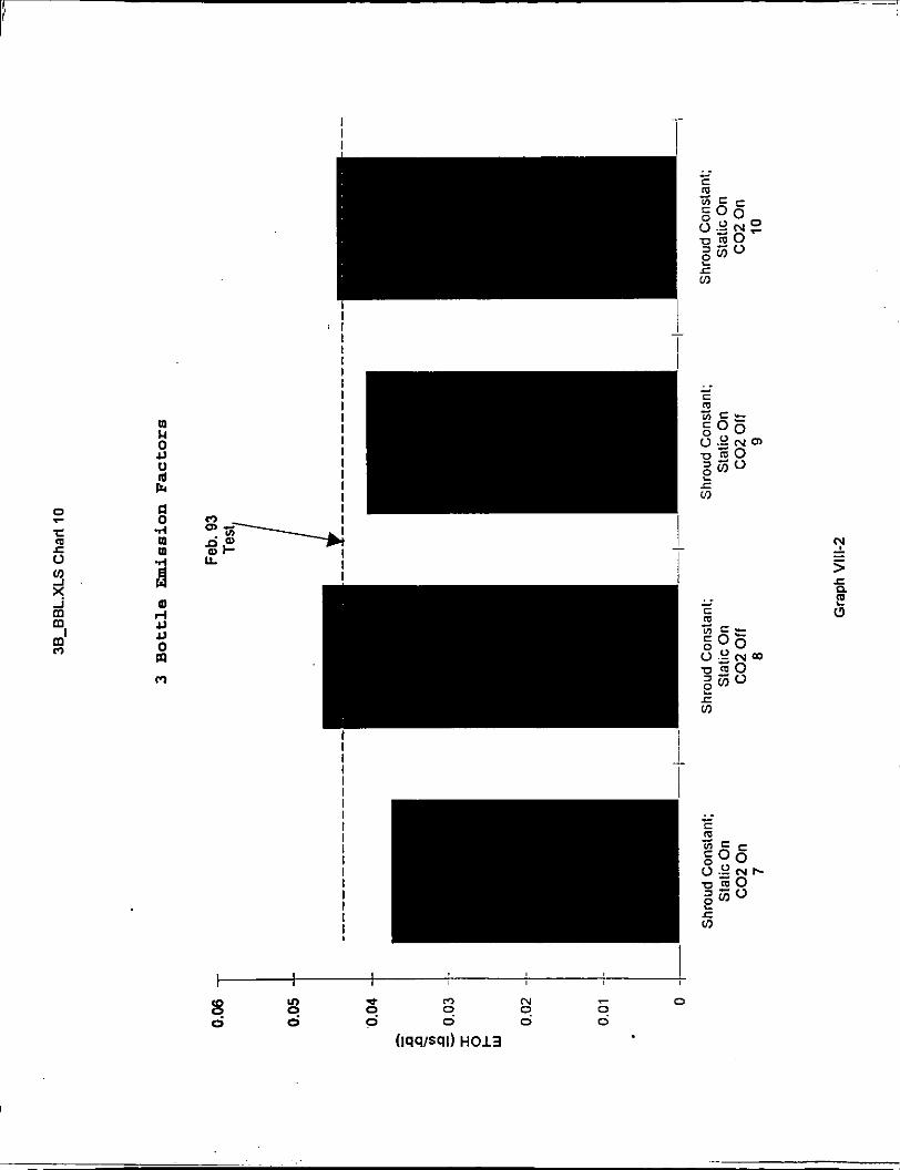
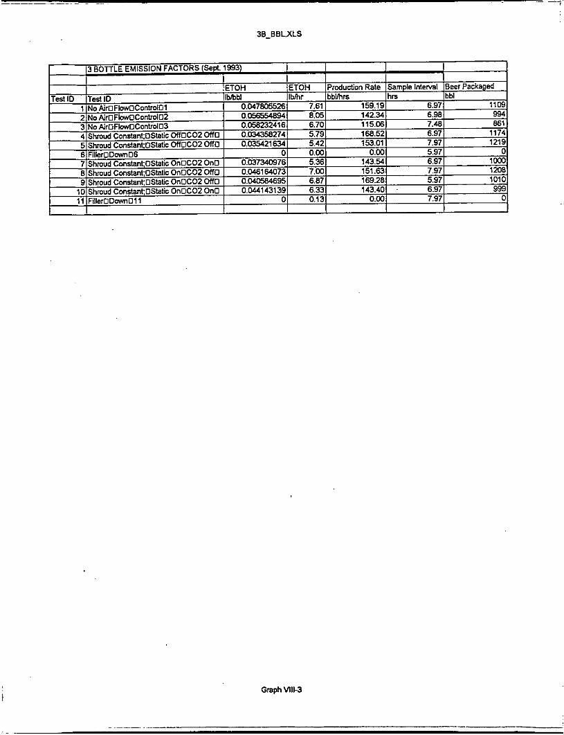
A statistical box plot of the emission rates (lbs/hr) for all of the 3 Bottle VOC tests are presented in Graph VII. Graph VI11 presents the emission factors (lbs/bbl) for the same set of tests,
The raw data from all the tests are contained in Appendix D.
The tests resulted in emission decreases of 25% or less. Therefore, we believe that the major source of ethanol emissions in bottle filling has not yet been discovered.
1. Air Flow Control.
Decreasing only the filler shroud air flow resulted in an ethanol emissions reduction of 25% [tests 1,2,3 (7.45 lbs/hr) versus 4,5 (5.61 lbs/hr) I .
Emission factors, for shroud air flow control only, showed a reduction of 36% (0.0542 lbs/bbl to 0.0349 lbs/bbl) .
Note: All charts and graphs are located in Appendix A.
. .
2 .
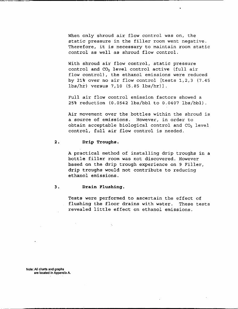
When only shroud air flow control was on, the static pressure in the filler room went negative. Therefore, it is necessary to maintain room static control as well as shroud flow control.
With shroud air flow control, static pressure control and CO, level control active (full air flow control), the ethanol emissions were reduced by 21% over no air flow control [tests 1 ,2 ,3 ( 7 . 4 5 lbs/hr) versus 7,lO (5.85 lbs/hr)l .
Full air flow control emission factors showed a 25% reduction ( 0 . 0 5 4 2 lbs/bbl to 0 . 0 4 0 7 lbs/bbl).
Air movement over the bottles within the shroud is a source of emissions. However, in order to obtain acceptable biological control and CO, level control, full air flow control is needed.
D r i p Troughs.
A practical method of installing drip troughs in a bottle filler room was not discovered. However based on the drip trough experience on 9 Filler, drip troughs would not contribute to reducing ethanol emissions.
3 . D r a i n Flushing.
Tests were performed to ascertain the effect of flushing the floor drains with water. These tests revealed little effect on ethanol emissions.
Note: All chanS and graphs are located in Appendix A.
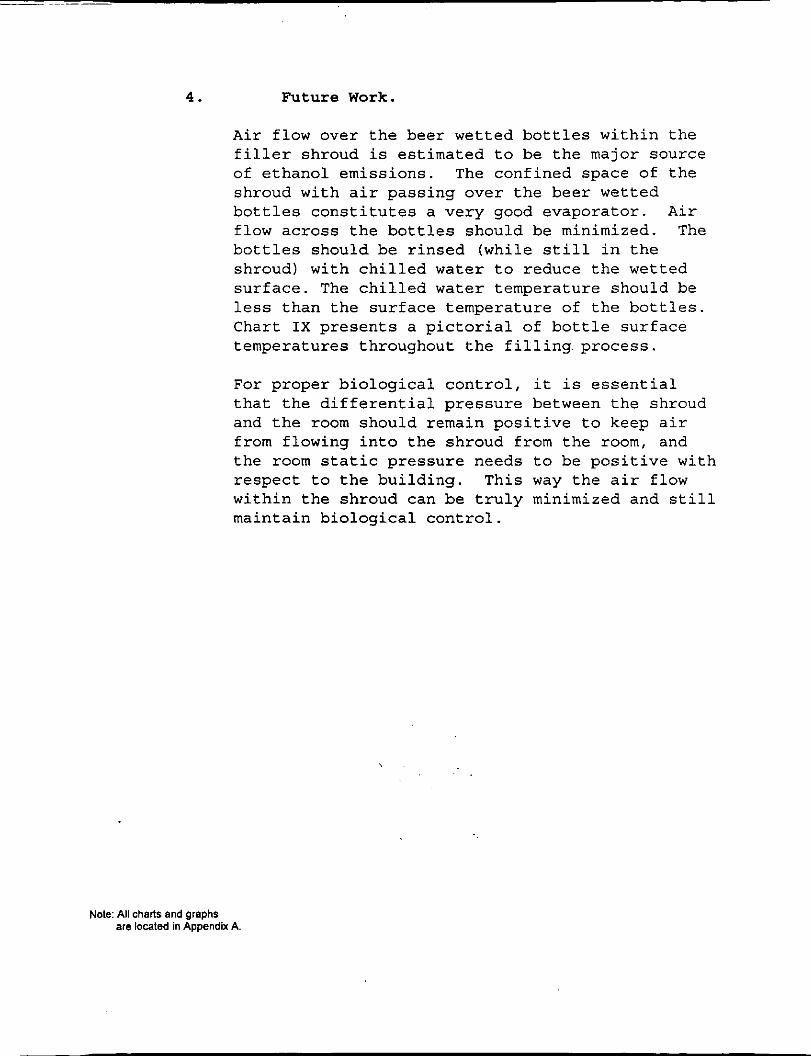
4 . Future Work.
Air flow over the beer wetted bottles within the filler shroud is estimated to be the major source of ethanol emissions. The confined space of the shroud with air passing over the beer wetted bottles constitutes a very good evaporator. Air flow across the bottles should be minimized. The bottles should be rinsed (while still in the shroud) with chilled water to reduce the wetted surface. The chilled water temperature should be less than the surface temperature of the bottles. Chart IX presents a pictorial of bottle surface temperatures throughout the filling. process.
For proper biological control, it is essential that the differential pressure between the shroud and the room should remain positive to keep air from flowing into the shroud from the room, and the room static pressure needs to be positive with respect to the building. This way the air flow within the shroud can be truly minimized and still maintain biological control.
Note: All charts and graphs are located in Appendix A.
‘ PARTIAL DRIP TROUGHS - SHORT LIP - BEER RELEASED TO FLOOR
Page C-2
L
9c:o L 9o:o 1
L
8P:L
I I I 0Z:L
O Z g s b O I L Y 0 5 : - O m N
, I
- , 0 0
(wdd)auedoJd
J
2 m W
t 0 d
-- __ _ _ -- -- _- _ _ -- ._
-- -- -- __ __ -- __ __ -- --
I
0 N
Pz:oP:Ez PZ:Zl:EZ Pz:PP:zz Pz:Sl:Zz P C 8 P : I Z P z : o z : c z P z : z s : o z Pz :Pz:oz PZ:9S:61 PZ:8Z:61 PZ:00:61 PZ:ZE:81 Pz:P0:81 PZ:SE:Ll
__ PZ:80:Ll -- Pz:oP:S l
_-
__ P z : z l : S l 0
-- P z : 9 l : s c 0
__ Pz:8P:Pl -- Pz:oz :Pc
PZ:ZS:E 1 -- Pz:Pz:Ec -- P z : s S : z l _ _ Pz:Qz:ZI -- P z : o o : z l __ PZ:ZE: 11
:I Pz:PP:s l 2 _-
__ _-
--
_ _ -- P z : P o : l c -- EZ:SE:Ol _ _ EZ:80:01 -- EZ:OP:6 _ _ €Z:Z1:6 -- Ez:PP:8 -- Ez:91:8 __ EZ:8P:L
Ez:OZ:L
_-
-_
_-
0
rc3 0 0
N
m I 4
2 $; g k P I 0 m:
(d U rJY
I I
PZ:SZ:EZ P z : o P : z z *z:ss: cz *z:o 1: LZ P z : s z : o z PZ:OP:6 1 Pz:s s :eL PZ:01:81 PZ:SZ:LL Pz:oP:91 Pz : s s : sL P z : o c : s 1 Pz:sz:PL PZ:OP:El PZ:SS:Zl n
2 Pz:OL:zL s P z : s z : 1 c g EZ:Ov:OL EZ:SS:6 EZ:0!:6
S N Z O G Z Z s v cz 00: 1z s1:oz OE:61. SVQL 0O:Ql S K L C OE:9c s*:s 1 00:s 1 SWL 0 E : E l s w c - F! 0o:zL. - 0E:O c SV6 00:6 S L 8 0E:L SV9 00:9 s1:s O W SVE 0O:E sc:z OE: c s*:o 0o:o
s1:I.c g
2 3
c
_ _ 1- 00:6 :I S1:8
0E:L S V 9 00:9 s1:s O W SVE 00:c s1:z OE: 1 SVO 0o:o