44
CATALOGUE M400 | DECEMBER 2013 WWW.TCF.COM INDUSTRIAL PROCESS AND COMMERCIAL VENTILATION SYSTEMS Twin City Fan BACKWARD CURVED HIGH PRESSURE FANS MODEL BCS
CATALOGUE M400 | DECEMBER 2013 WWW.TCF.COM
INDUSTRIAL PROCESS AND
COMMERCIAL VENTILATION SYSTEMS
Twin City Fan
Twin City FanBACKWARD CURVED HIGH PRESSURE FANSMODEL BCS

TWIN CITY FAN - CATALOGUE M4002
Arrangement 1 with unitary base and belt guard
Arrangement 9F
Model BCSBackward Curved - High Pressure
The BCS fan from Twin City Fan & Blower is a high efficiency backward curved industrial fan designed for handling relatively clean air in high pressure appli-cations. Typical applications include combustion air, product cooling, moisture blow-off, forced draft on fluid bed boilers, and induced draft after baghouse process blowers.
Because the BCS features a wider impeller and housing, producing a high volume of air at a lower velocity, the need for an expansion evasé is eliminated.
BCS fans are available with a variety of construction options and accessories, offering the versatility and flex-ibility required in today's industrial applications.
Sizes419 to 2260 mm impeller diameters
PerformanceAirflow to 200 m3/sec at 500 PaStatic pressure to 9945 PaAirstream temperatures to 425°C
Arrangements1, 3SI, 4, 7SI, 8, 9 and 9F
Drive ConfigurationsAvailable in both direct and belt drive configurations.
Construction• Design 14 — for tip speeds up to 70 m/s• Design 17 — for tip speeds up to 85 m/s• Design 22 — for tip speeds up to 110 m/s• Design 26 — for tip speeds up to 130 m/s
HousingsHeavy-gauge, reinforced, continuously welded housings provide strength and durability for extended service life — a necessity in all commercial and industrial installa-tions. Outlet flanges for duct-connection as well as rigidity are standard. Inlet collars for slip-joint connection and lifting lugs are also standard. All housings are reinforced with rigid bracing to increase structural integrity. The support angles are intermittently welded and caulked between welds to prevent bleed-through corrosion. Precisely positioned cutoff plates and aerodynamically spun inlet cones provide high efficiency and smooth airflow through the fan.
CENTRIFUGAL FANS

WWW.TCF.COM 3
BCS ImpellerThe BCS impeller features heavy-gauge steel construc-tion and a non-overloading impeller design, suitable for applications requiring large volumes of air at moderate to high pressures. The high efficiency impeller features backward curved blades of single thickness, continuously welded to the rim and backplate. A conical spun shroud (rim) makes BCS fans less susceptible to the performance losses associated with poor inlet conditions. All BCS impellers are statically and dynamically bal-anced to grade G6.3 per ANSI S2.19 (3.8 mm/s rms) for smooth operation prior to assembly of the fan, followed by a final balance of the entire rotating assembly.
ShaftShafts are AISI-1018, 1040 or 1045 hot-rolled steel accurately turned, ground, polished, and ring gauged for accuracy. Shafts are generously sized for first critical speed of at least 1.43 times the maximum speed for the class.
BearingsBearings are heavy-duty, grease-lubricated, anti-friction ball or roller, self-aligning, pillow block type and are selected for minimum average bearing life L10 in excess of 40,000 hours at the maximum fan RPM.
Rotation and DischargeBoth clockwise and counterclockwise rotations are avail-able in various standard discharge positions. See draw-ings on pages 28-41.
Temperature LimitsStandard construction designed for temperatures up to 150°C. Optional construction available to handle up to 425°C. See page 7.
Outlet FlangePunched outlet flange is provided as standard construc-tion on all sizes.
Mechanical Run Test & Final Vibration CheckAll fans are assembled for a mechanical run test as well as final balance prior to shipment. Vibration readings are taken on both fan bearings in the axial, horizontal, and vertical directions at the specified speed. Fans are bal-anced to 3.8 mm/s rms. peak or less.
Special MaterialsBCS fans can be constructed of special materials such as aluminum or stainless steel.
Arrangement 1
BCS Impeller
CONSTRUCTION FEATURES
Twin City Fan
Twin City Fan
TWIN CITY FAN - CATALOGUE M4004
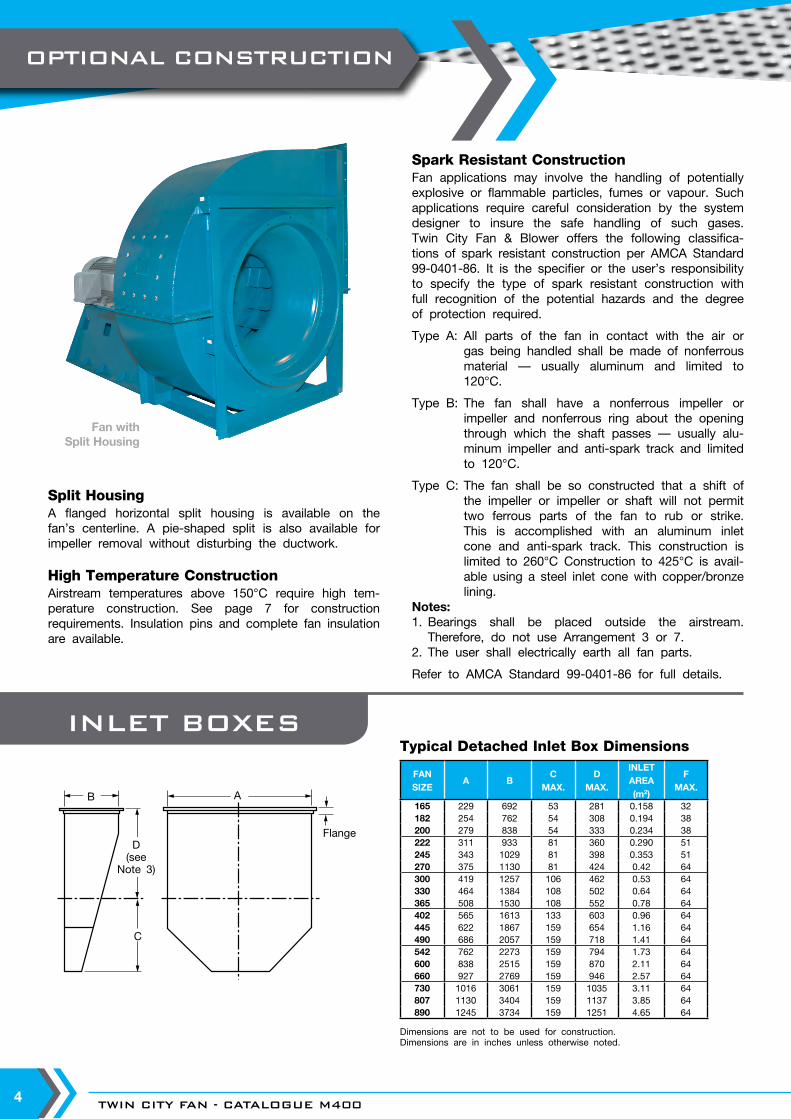
Split HousingA flanged horizontal split housing is available on the fan’s centerline. A pie-shaped split is also available for impeller removal without disturbing the ductwork.
High Temperature ConstructionAirstream temperatures above 150°C require high tem-perature construction. See page 7 for construction requirements. Insulation pins and complete fan insulation are available.
Spark Resistant ConstructionFan applications may involve the handling of potentially explosive or flammable particles, fumes or vapour. Such applications require careful consideration by the system designer to insure the safe handling of such gases. Twin City Fan & Blower offers the following classifica-tions of spark resistant construction per AMCA Standard 99-0401-86. It is the specifier or the user’s responsibility to specify the type of spark resistant construction with full recognition of the potential hazards and the degree of protection required.
Type A: All parts of the fan in contact with the air or gas being handled shall be made of nonferrous material — usually aluminum and limited to 120°C.
Type B: The fan shall have a nonferrous impeller or impeller and nonferrous ring about the opening through which the shaft passes — usually alu-minum impeller and anti-spark track and limited to 120°C.
Type C: The fan shall be so constructed that a shift of the impeller or impeller or shaft will not permit two ferrous parts of the fan to rub or strike. This is accomplished with an aluminum inlet cone and anti-spark track. This construction is limited to 260°C Construction to 425°C is avail-able using a steel inlet cone with copper/bronze lining.
Notes:1. Bearings shall be placed outside the airstream.
Therefore, do not use Arrangement 3 or 7.2. The user shall electrically earth all fan parts.
Refer to AMCA Standard 99-0401-86 for full details.
B A
Flange
C
D(see
Note 3)
Dimensions are not to be used for construction.Dimensions are in inches unless otherwise noted.
Fan withSplit Housing
INLET BOXESTypical Detached Inlet Box Dimensions
FANSIZE
A BC
MAX.D
MAX.
INLET AREA (m2)
FMAX.
165 229 692 53 281 0.158 32182 254 762 54 308 0.194 38200 279 838 54 333 0.234 38222 311 933 81 360 0.290 51245 343 1029 81 398 0.353 51270 375 1130 81 424 0.42 64300 419 1257 106 462 0.53 64330 464 1384 108 502 0.64 64365 508 1530 108 552 0.78 64402 565 1613 133 603 0.96 64445 622 1867 159 654 1.16 64490 686 2057 159 718 1.41 64542 762 2273 159 794 1.73 64600 838 2515 159 870 2.11 64660 927 2769 159 946 2.57 64730 1016 3061 159 1035 3.11 64807 1130 3404 159 1137 3.85 64890 1245 3734 159 1251 4.65 64
OPTIONAL CONSTRUCTION
WWW.TCF.COM 5
270°270
225
225°
180
180°
135
135°
9090°
45
45°
360
360°
315
315°
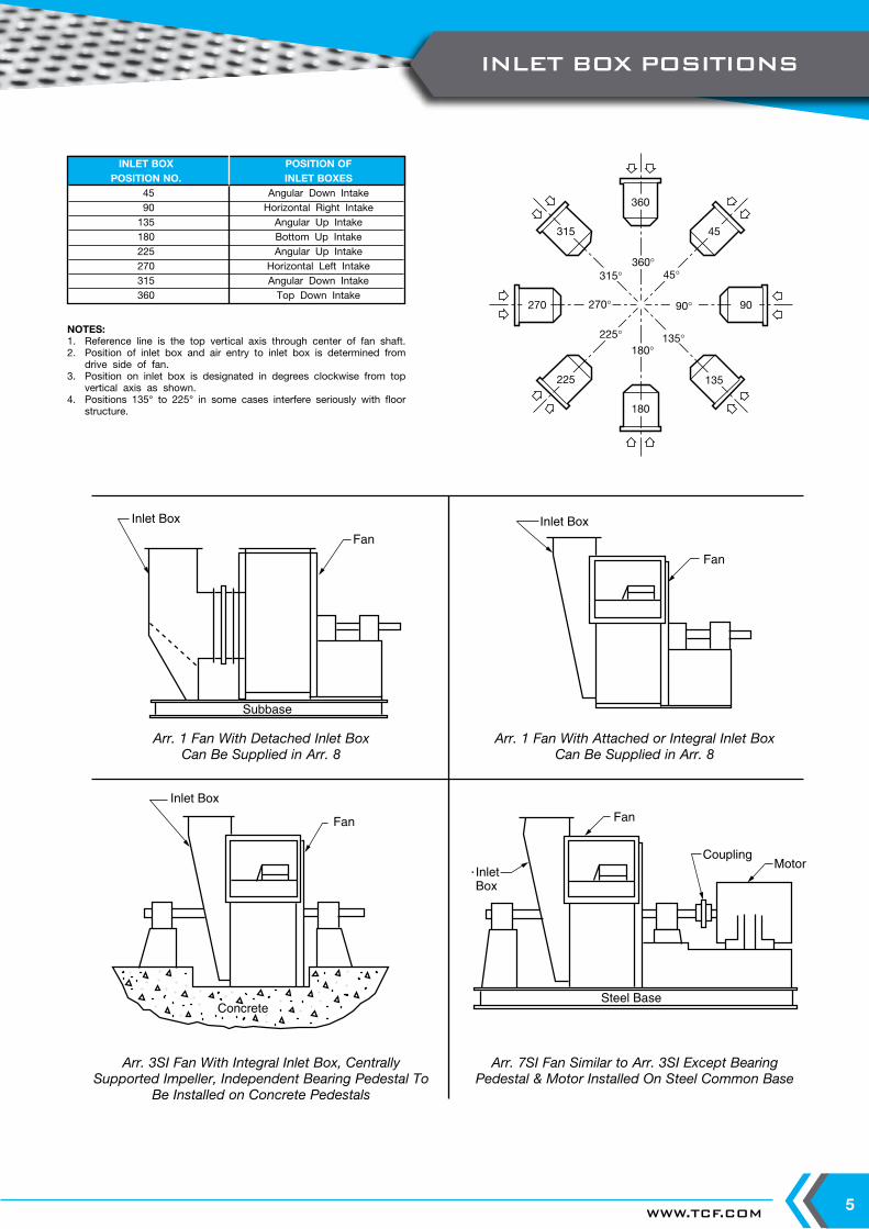
NOTES:1. Reference line is the top vertical axis through center of fan shaft.2. Position of inlet box and air entry to inlet box is determined from
drive side of fan.3. Position on inlet box is designated in degrees clockwise from top
vertical axis as shown.4. Positions 135° to 225° in some cases interfere seriously with floor
structure.
Inlet Box
Fan
Subbase
Inlet Box
Fan
Inlet Box
Fan
Concrete
Fan
CouplingMotor
InletBox
Steel Base
Arr. 1 Fan With Detached Inlet BoxCan Be Supplied in Arr. 8
Arr. 1 Fan With Attached or Integral Inlet BoxCan Be Supplied in Arr. 8
Arr. 3SI Fan With Integral Inlet Box, Centrally Supported Impeller, Independent Bearing Pedestal To
Be Installed on Concrete Pedestals
Arr. 7SI Fan Similar to Arr. 3SI Except Bearing Pedestal & Motor Installed On Steel Common Base
INLET BOX POSITION OF POSITION NO. INLET BOXES 45 Angular Down Intake 90 Horizontal Right Intake 135 Angular Up Intake 180 Bottom Up Intake 225 Angular Up Intake 270 Horizontal Left Intake 315 Angular Down Intake 360 Top Down Intake
INLET BOX POSITIONS

TWIN CITY FAN - CATALOGUE M4006
Inlet BoxAn inlet box is designed to minimize pressure drop and is recommended for applications where uniform flow is difficult to obtain due to limited space. Inlet boxes can be designed to be either detachable or integral to the fan.
Inlet Box DamperThe inlet box damper pre-spins the air in the direction of impeller rotation, resulting in a savings in consumed power at reduced loads.
Outlet DampersDouble surface aerofoil blades are available in either parallel or opposed blade design.
Fan GuardsShaft, bearing, and belt guards are available in OSHA type designs.
Access DoorBolted, quick-opening, and raised bolted access doors are available for impeller inspection or maintenance.
Variable Inlet VanesVariable inlet vanes are available to provide economical, stable, and efficient air volume control for manual or motorized operation. Nested inlet vanes are available for Design 17 and are suitable for temperatures to 150°C. External inlet vanes are available for Design 22 and 26 and are suitable for temperatures to 150°C. Construction to 315°C is available for both.
Shaft SealsA variety of shaft seals are available to prevent contami-nants in the airstream from passing through the shaft hole in the fan housing. The shaft seal is provided as standard on all fans with applications over 150°C and fans with split housings. Although shaft seals minimize air leakage, they are not an air-tight design.
DrainAll fans are constructed with a drain hole in the bottom of the housing. A threaded pipe coupling is welded to the lowest point in the housing scroll to permit wash water or condensation to drain from the fan.
Flanged InletA punched inlet flange is available for duct mounting.
Temperature and Vibration DetectorsThermocouples or RTDs are available to install on the bearings. A variety of vibration switches are available.
Vibration Isolation BasesStructural angle, structural channel, inertia bases, and unitary bases are available with or without spring isola-tors.
ScreensSafety screens are available for mounting in the fan inlet or outlet in non-ducted applications.
External Inlet Vanes
Shaft SealSafety Screen
Belt & Shaft Guard
Nested Inlet Vanes
Raised BoltedAccess Door
Quick-OpenAccess Door
BoltedAccess Door
PRODUCT ACCESSORIES
WWW.TCF.COM 7
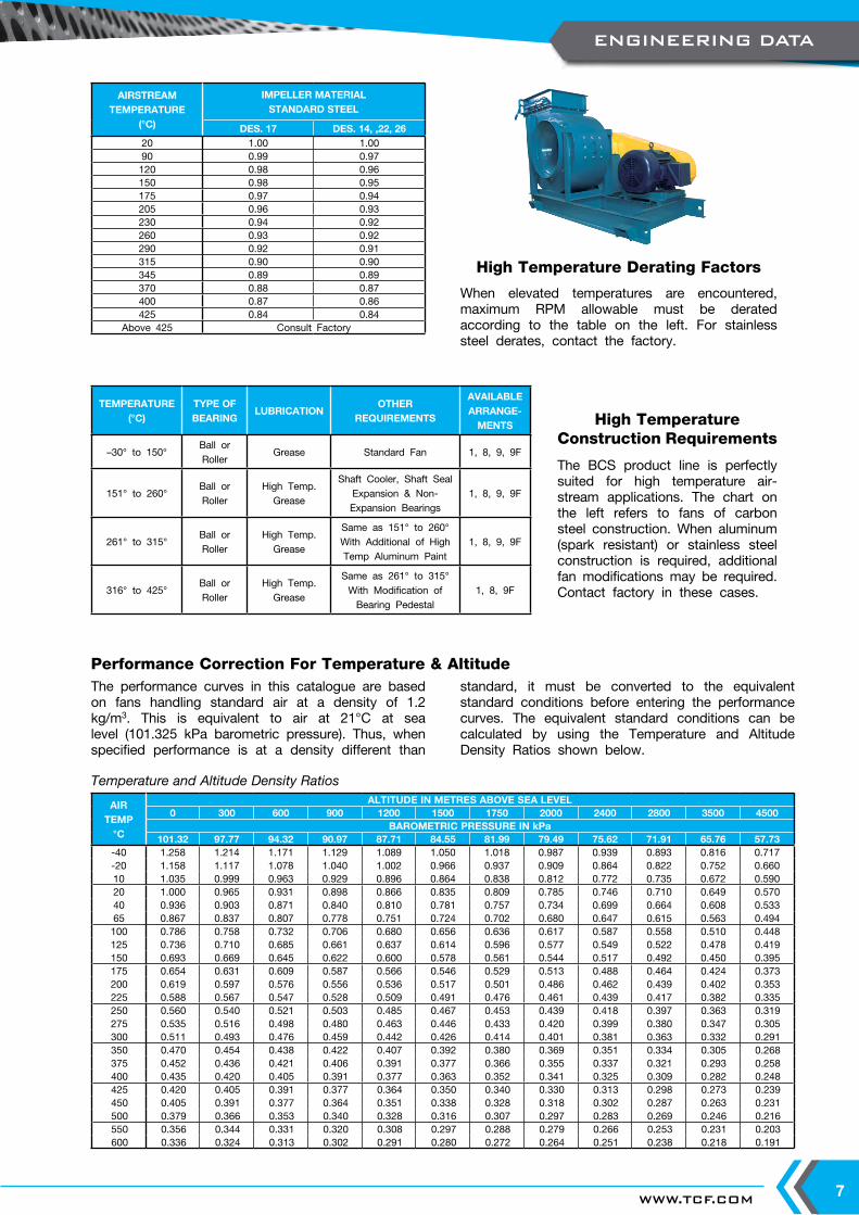
The BCS product line is perfectly suited for high temperature air-stream applications. The chart on the left refers to fans of carbon steel construction. When aluminum (spark resistant) or stainless steel construction is required, additional fan modifications may be required. Contact factory in these cases.
High Temperature Construction Requirements
The performance curves in this catalogue are based on fans handling standard air at a density of 1.2 kg/m3. This is equivalent to air at 21°C at sea level (101.325 kPa barometric pressure). Thus, when specified performance is at a density different than
standard, it must be converted to the equivalent standard conditions before entering the performance curves. The equivalent standard conditions can be calculated by using the Temperature and Altitude Density Ratios shown below.
Performance Correction For Temperature & Altitude
When elevated temperatures are encountered, maximum RPM allowable must be derated according to the table on the left. For stainless steel derates, contact the factory.
High Temperature Derating Factors
TEMPERATURE (°C)
TYPE OFBEARING
LUBRICATIONOTHER
REQUIREMENTS
AVAILABLE ARRANGE-
MENTS
–30° to 150°Ball or Roller
Grease Standard Fan 1, 8, 9, 9F
151° to 260°Ball or Roller
High Temp.Grease
Shaft Cooler, Shaft SealExpansion & Non-Expansion Bearings
1, 8, 9, 9F
261° to 315°Ball or Roller
High Temp.Grease
Same as 151° to 260° With Additional of High Temp Aluminum Paint
1, 8, 9, 9F
316° to 425°Ball or Roller
High Temp.Grease
Same as 261° to 315° With Modification of Bearing Pedestal
1, 8, 9F
AIRSTREAM TEMPERATURE
(°C)
IMPELLER MATERIALSTANDARD STEEL
DES. 17 DES. 14, ,22, 2620 1.00 1.0090 0.99 0.97120 0.98 0.96150 0.98 0.95175 0.97 0.94205 0.96 0.93230 0.94 0.92260 0.93 0.92290 0.92 0.91315 0.90 0.90345 0.89 0.89370 0.88 0.87400 0.87 0.86425 0.84 0.84
Above 425 Consult Factory
Temperature and Altitude Density Ratios
AIRTEMP
°C
ALTITUDE IN METRES ABOVE SEA LEVEL0 300 600 900 1200 1500 1750 2000 2400 2800 3500 4500
BAROMETRIC PRESSURE IN kPa101.32 97.77 94.32 90.97 87.71 84.55 81.99 79.49 75.62 71.91 65.76 57.73
-40 1.258 1.214 1.171 1.129 1.089 1.050 1.018 0.987 0.939 0.893 0.816 0.717-20 1.158 1.117 1.078 1.040 1.002 0.966 0.937 0.909 0.864 0.822 0.752 0.66010 1.035 0.999 0.963 0.929 0.896 0.864 0.838 0.812 0.772 0.735 0.672 0.59020 1.000 0.965 0.931 0.898 0.866 0.835 0.809 0.785 0.746 0.710 0.649 0.57040 0.936 0.903 0.871 0.840 0.810 0.781 0.757 0.734 0.699 0.664 0.608 0.53365 0.867 0.837 0.807 0.778 0.751 0.724 0.702 0.680 0.647 0.615 0.563 0.494100 0.786 0.758 0.732 0.706 0.680 0.656 0.636 0.617 0.587 0.558 0.510 0.448125 0.736 0.710 0.685 0.661 0.637 0.614 0.596 0.577 0.549 0.522 0.478 0.419150 0.693 0.669 0.645 0.622 0.600 0.578 0.561 0.544 0.517 0.492 0.450 0.395175 0.654 0.631 0.609 0.587 0.566 0.546 0.529 0.513 0.488 0.464 0.424 0.373200 0.619 0.597 0.576 0.556 0.536 0.517 0.501 0.486 0.462 0.439 0.402 0.353225 0.588 0.567 0.547 0.528 0.509 0.491 0.476 0.461 0.439 0.417 0.382 0.335250 0.560 0.540 0.521 0.503 0.485 0.467 0.453 0.439 0.418 0.397 0.363 0.319275 0.535 0.516 0.498 0.480 0.463 0.446 0.433 0.420 0.399 0.380 0.347 0.305300 0.511 0.493 0.476 0.459 0.442 0.426 0.414 0.401 0.381 0.363 0.332 0.291350 0.470 0.454 0.438 0.422 0.407 0.392 0.380 0.369 0.351 0.334 0.305 0.268375 0.452 0.436 0.421 0.406 0.391 0.377 0.366 0.355 0.337 0.321 0.293 0.258400 0.435 0.420 0.405 0.391 0.377 0.363 0.352 0.341 0.325 0.309 0.282 0.248425 0.420 0.405 0.391 0.377 0.364 0.350 0.340 0.330 0.313 0.298 0.273 0.239450 0.405 0.391 0.377 0.364 0.351 0.338 0.328 0.318 0.302 0.287 0.263 0.231500 0.379 0.366 0.353 0.340 0.328 0.316 0.307 0.297 0.283 0.269 0.246 0.216550 0.356 0.344 0.331 0.320 0.308 0.297 0.288 0.279 0.266 0.253 0.231 0.203600 0.336 0.324 0.313 0.302 0.291 0.280 0.272 0.264 0.251 0.238 0.218 0.191
ENGINEERING DATA
TWIN CITY FAN - CATALOGUE M4008
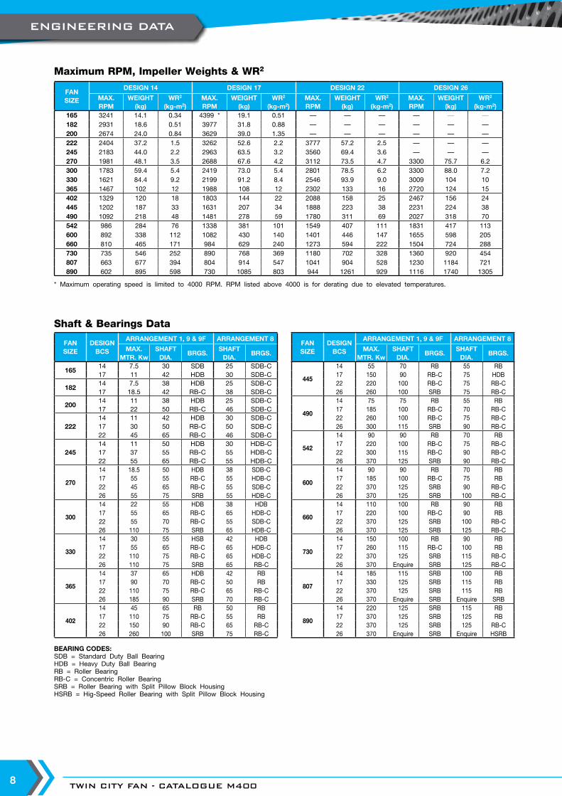
Maximum RPM, Impeller Weights & WR2
Shaft & Bearings Data
BEARING CODES:SDB = Standard Duty Ball BearingHDB = Heavy Duty Ball BearingRB = Roller BearingRB-C = Concentric Roller BearingSRB = Roller Bearing with Split Pillow Block HousingHSRB = Hig-Speed Roller Bearing with Split Pillow Block Housing
FANSIZE
DESIGN 14 DESIGN 17 DESIGN 22 DESIGN 26
MAX. RPM
WEIGHT (kg)
WR2
(kg-m2)MAX. RPM
WEIGHT (kg)
WR2
(kg-m2)MAX. RPM
WEIGHT (kg)
WR2
(kg-m2)MAX. RPM
WEIGHT (kg)
WR2
(kg-m2)165 3241 14.1 0.34 4399 * 19.1 0.51 — — — — — —182 2931 18.6 0.51 3977 31.8 0.88 — — — — — —200 2674 24.0 0.84 3629 39.0 1.35 — — — — — —222 2404 37.2 1.5 3262 52.6 2.2 3777 57.2 2.5 — — —245 2183 44.0 2.2 2963 63.5 3.2 3560 69.4 3.6 — — —270 1981 48.1 3.5 2688 67.6 4.2 3112 73.5 4.7 3300 75.7 6.2300 1783 59.4 5.4 2419 73.0 5.4 2801 78.5 6.2 3300 88.0 7.2330 1621 84.4 9.2 2199 91.2 8.4 2546 93.9 9.0 3009 104 10365 1467 102 12 1988 108 12 2302 133 16 2720 124 15402 1329 120 18 1803 144 22 2088 158 25 2467 156 24445 1202 187 33 1631 207 34 1888 223 38 2231 224 38490 1092 218 48 1481 278 59 1780 311 69 2027 318 70542 986 284 76 1338 381 101 1549 407 111 1831 417 113600 892 338 112 1082 430 140 1401 446 147 1655 598 205660 810 465 171 984 629 240 1273 594 222 1504 724 288730 735 546 252 890 768 369 1180 702 328 1360 920 454807 663 677 394 804 914 547 1041 904 528 1230 1184 721890 602 895 598 730 1085 803 944 1261 929 1116 1740 1305
FANSIZE
DESIGN BCS
ARRANGEMENT 1, 9 & 9F ARRANGEMENT 8
MAX. MTR. Kw
SHAFT DIA.
BRGS.SHAFT
DIA.BRGS.
16514 7.5 30 SDB 25 SDB-C17 11 42 HDB 30 SDB-C
18214 7.5 38 HDB 25 SDB-C17 18.5 42 RB-C 38 SDB-C
20014 11 38 HDB 25 SDB-C17 22 50 RB-C 46 SDB-C
22214 11 42 HDB 30 SDB-C17 30 50 RB-C 50 SDB-C22 45 65 RB-C 46 SDB-C
24514 11 50 HDB 30 HDB-C17 37 55 RB-C 55 HDB-C22 55 65 RB-C 55 HDB-C
270
14 18.5 50 HDB 38 SDB-C17 55 55 RB-C 55 HDB-C22 45 65 RB-C 55 SDB-C26 55 75 SRB 55 HDB-C
300
14 22 55 HDB 38 HDB17 55 65 RB-C 65 HDB-C22 55 70 RB-C 55 SDB-C26 110 75 SRB 65 HDB-C
330
14 30 55 HSB 42 HDB17 55 65 RB-C 65 HDB-C22 110 75 RB-C 65 HDB-C26 110 75 SRB 65 RB-C
365
14 37 65 HDB 42 RB17 90 70 RB-C 50 RB22 110 75 RB-C 65 RB-C26 185 90 SRB 70 RB-C
402
14 45 65 RB 50 RB17 110 75 RB-C 55 RB22 150 90 RB-C 65 RB-C26 260 100 SRB 75 RB-C
FANSIZE
DESIGN BCS
ARRANGEMENT 1, 9 & 9F ARRANGEMENT 8
MAX. MTR. Kw
SHAFT DIA.
BRGS.SHAFT
DIA.BRGS.
445
14 55 70 RB 55 RB17 150 90 RB-C 75 HDB22 220 100 RB-C 75 RB-C26 260 100 SRB 75 RB-C
490
14 75 75 RB 55 RB17 185 100 RB-C 70 RB-C22 260 100 RB-C 75 RB-C26 300 115 SRB 90 RB-C
542
14 90 90 RB 70 RB17 220 100 RB-C 75 RB-C22 300 115 RB-C 90 RB-C26 370 125 SRB 90 RB-C
600
14 90 90 RB 70 RB17 185 100 RB-C 75 RB22 370 125 SRB 90 RB-C26 370 125 SRB 100 RB-C
660
14 110 100 RB 90 RB17 220 100 RB-C 90 RB22 370 125 SRB 100 RB-C26 370 125 SRB 125 RB-C
730
14 150 100 RB 90 RB17 260 115 RB-C 100 RB22 370 125 SRB 115 RB-C26 370 Enquire SRB 125 RB-C
807
14 185 115 SRB 100 RB17 330 125 SRB 115 RB22 370 125 SRB 115 RB26 370 Enquire SRB Enquire SRB
890
14 220 125 SRB 115 RB17 370 125 SRB 125 RB22 370 125 SRB 125 RB-C26 370 Enquire SRB Enquire HSRB
* Maximum operating speed is limited to 4000 RPM. RPM listed above 4000 is for derating due to elevated temperatures.
ENGINEERING DATA
WWW.TCF.COM 9
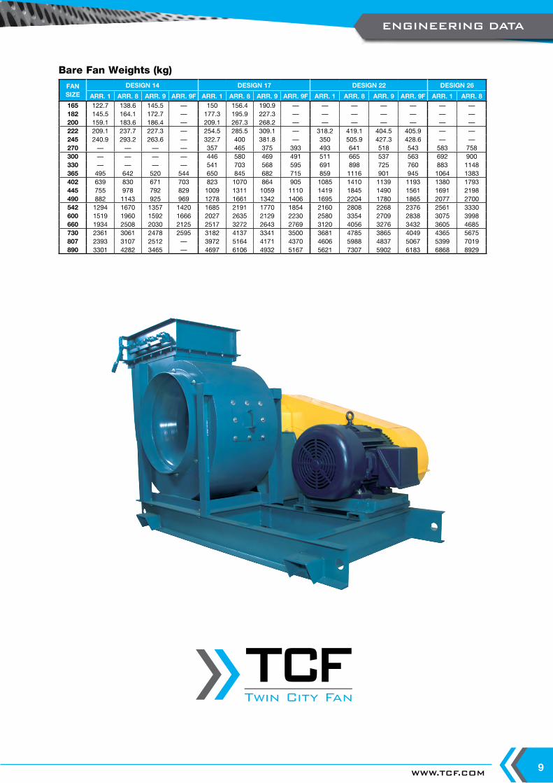
Bare Fan Weights (kg)FANSIZE
DESIGN 14 DESIGN 17 DESIGN 22 DESIGN 26
ARR. 1 ARR. 8 ARR. 9 ARR. 9F ARR. 1 ARR. 8 ARR. 9 ARR. 9F ARR. 1 ARR. 8 ARR. 9 ARR. 9F ARR. 1 ARR. 8165 122.7 138.6 145.5 — 150 156.4 190.9 — — — — — — —182 145.5 164.1 172.7 — 177.3 195.9 227.3 — — — — — — —200 159.1 183.6 186.4 — 209.1 267.3 268.2 — — — — — — —222 209.1 237.7 227.3 — 254.5 285.5 309.1 — 318.2 419.1 404.5 405.9 — —245 240.9 293.2 263.6 — 322.7 400 381.8 — 350 505.9 427.3 428.6 — —270 — — — — 357 465 375 393 493 641 518 543 583 758300 — — — — 446 580 469 491 511 665 537 563 692 900330 — — — — 541 703 568 595 691 898 725 760 883 1148365 495 642 520 544 650 845 682 715 859 1116 901 945 1064 1383402 639 830 671 703 823 1070 864 905 1085 1410 1139 1193 1380 1793445 755 978 792 829 1009 1311 1059 1110 1419 1845 1490 1561 1691 2198490 882 1143 925 969 1278 1661 1342 1406 1695 2204 1780 1865 2077 2700542 1294 1670 1357 1420 1685 2191 1770 1854 2160 2808 2268 2376 2561 3330600 1519 1960 1592 1666 2027 2635 2129 2230 2580 3354 2709 2838 3075 3998660 1934 2508 2030 2125 2517 3272 2643 2769 3120 4056 3276 3432 3605 4685730 2361 3061 2478 2595 3182 4137 3341 3500 3681 4785 3865 4049 4365 5675807 2393 3107 2512 — 3972 5164 4171 4370 4606 5988 4837 5067 5399 7019890 3301 4282 3465 — 4697 6106 4932 5167 5621 7307 5902 6183 6868 8929
ENGINEERING DATA
Twin City Fan
Twin City Fan

TWIN CITY FAN - CATALOGUE M40010
Notes:1. Performance certified is for Installation Type B & D: Free or ducted inlet, ducted outlet.2. Power rating (kW) does not include transmission losses.3. Performance ratings do not include the effects of appurtenances (accessories).4. The sound power level ratings shown are in decibels, referred to 10 E-12 watts calculated per AMCA Standard 301.5. Values shown are for inlet LwiA sound power levels for Installation Type B: Free inlet, ducted outlet.6. Ratings do not include the effects of duct end correction.7. The A-weighted sound ratings shown have been calculated per AMCA Standard 301.
12 40.4 0.6 0.8
qv - Flow (m³ / sec)
40
60
80
100
200
400
600
800
1,000
2,000
4,000
Pf - Fa
n To
tal Press
ure
(Pa)
720 RPM
960 RPM
1450 RPM
2000 RPM
2500 RPM
2850 RPM
3500 RPM
0.18kW
0.25kW
0.37kW
0.55kW
0.75kW
1.1kW
1.5kW
2.2kW
3kW
4kW
5.5kW
7.5kW
72% P
k. Eff.
68% Eff.
61% Eff.
BCS 165
qv - Flow (CFM) (in Thousands)0.7 1 2 3 5 71.5
Pf - Fa
n To
tal Press
ure
(in W
.G.)
0.2
0.3
0.5
0.7
1
2
3
5
7
10
1.5
15
PERFORMANCE CURVES
WWW.TCF.COM 11
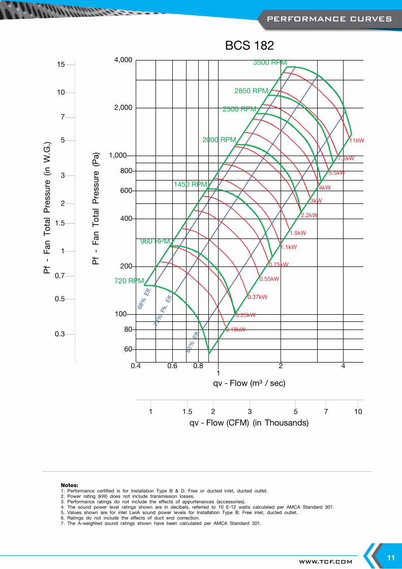
Notes:1. Performance certified is for Installation Type B & D: Free or ducted inlet, ducted outlet.2. Power rating (kW) does not include transmission losses.3. Performance ratings do not include the effects of appurtenances (accessories).4. The sound power level ratings shown are in decibels, referred to 10 E-12 watts calculated per AMCA Standard 301.5. Values shown are for inlet LwiA sound power levels for Installation Type B: Free inlet, ducted outlet.6. Ratings do not include the effects of duct end correction.7. The A-weighted sound ratings shown have been calculated per AMCA Standard 301.
12 40.4 0.6 0.8
qv - Flow (m³ / sec)
60
80
100
200
400
600
800
1,000
2,000
4,000
Pf - Fa
n To
tal Press
ure
(Pa)
720 RPM
960 RPM
1450 RPM
2000 RPM
2500 RPM
2850 RPM
3500 RPM
0.18kW
0.25kW
0.37kW
0.55kW
0.75kW
1.1kW
1.5kW
2.2kW
3kW
4kW
5.5kW
7.5kW
11kW
73% P
k. Eff.
68% Eff.
62% Eff.
BCS 182
qv - Flow (CFM) (in Thousands)1 2 3 5 7 101.5
Pf - Fa
n To
tal Press
ure
(in W
.G.)
0.3
0.5
0.7
1
2
3
5
7
10
1.5
15
PERFORMANCE CURVES
TWIN CITY FAN - CATALOGUE M40012
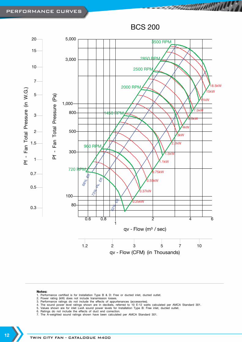
Notes:1. Performance certified is for Installation Type B & D: Free or ducted inlet, ducted outlet.2. Power rating (kW) does not include transmission losses.3. Performance ratings do not include the effects of appurtenances (accessories).4. The sound power level ratings shown are in decibels, referred to 10 E-12 watts calculated per AMCA Standard 301.5. Values shown are for inlet LwiA sound power levels for Installation Type B: Free inlet, ducted outlet.6. Ratings do not include the effects of duct end correction.7. The A-weighted sound ratings shown have been calculated per AMCA Standard 301.
12 4 60.6 0.8
qv - Flow (m³ / sec)
80
100
300
500
800
1,000
3,000
5,000
Pf - Fa
n To
tal Press
ure
(Pa)
720 RPM
960 RPM
1450 RPM
2000 RPM
2500 RPM
2850 RPM
3500 RPM
0.25kW
0.37kW
0.55kW
0.75kW
1.1kW
1.5kW
2.2kW
3kW
4kW
5.5kW
7.5kW
11kW
15kW
18.5kW
73% P
k. Eff.
68% Eff.
62% Eff.
BCS 200
qv - Flow (CFM) (in Thousands)2 3 5 7 101.2
Pf - Fa
n To
tal Press
ure
(in W
.G.)
0.3
0.5
0.7
1
2
3
5
7
10
20
1.5
15
PERFORMANCE CURVES

WWW.TCF.COM 13
Notes:1. Performance certified is for Installation Type B & D: Free or ducted inlet, ducted outlet.2. Power rating (kW) does not include transmission losses.3. Performance ratings do not include the effects of appurtenances (accessories).4. The sound power level ratings shown are in decibels, referred to 10 E-12 watts calculated per AMCA Standard 301.5. Values shown are for inlet LwiA sound power levels for Installation Type B: Free inlet, ducted outlet.6. Ratings do not include the effects of duct end correction.7. The A-weighted sound ratings shown have been calculated per AMCA Standard 301.
12 4 6 8
100.6 0.8
qv - Flow (m³ / sec)
40
60
80
100
200
400
600
800
1,000
2,000
4,000
6,000
Pf - Fa
n To
tal Press
ure
(Pa)
500 RPM
720 RPM
960 RPM
1450 RPM
2000 RPM
2500 RPM
2850 RPM
3500 RPM
0.25kW
0.37kW
0.55kW
0.75kW
1.1kW
1.5kW
2.2kW
3kW
4kW
5.5kW
7.5kW
11kW
15kW18.5kW22kW
30kW
37kW
77% P
k. Eff.
74% Eff.
68% Eff.
BCS 222
qv - Flow (CFM) (in Thousands)2 3 5 7 10 201.2 15
Pf - Fa
n To
tal Press
ure
(in W
.G.)
0.2
0.3
0.5
0.7
1
2
3
5
7
10
20
1.5
15
PERFORMANCE CURVES
TWIN CITY FAN - CATALOGUE M40014
Notes:1. Performance certified is for Installation Type B & D: Free or ducted inlet, ducted outlet.2. Power rating (kW) does not include transmission losses.3. Performance ratings do not include the effects of appurtenances (accessories).4. The sound power level ratings shown are in decibels, referred to 10 E-12 watts calculated per AMCA Standard 301.5. Values shown are for inlet LwiA sound power levels for Installation Type B: Free inlet, ducted outlet.6. Ratings do not include the effects of duct end correction.7. The A-weighted sound ratings shown have been calculated per AMCA Standard 301.
12 4 6 8
10200.8
qv - Flow (m³ / sec)
60
80
100
200
400
600
800
1,000
2,000
4,000
6,000
8,000
Pf - Fa
n To
tal Press
ure
(Pa)
500 RPM
720 RPM
960 RPM
1450 RPM
2000 RPM
2500 RPM
2850 RPM
3500 RPM
0.25kW
0.37kW
0.55kW
0.75kW
1.1kW
1.5kW
2.2kW
3kW
4kW
5.5kW
7.5kW
11kW
15kW
18.5kW22kW
30kW
37kW45kW
55kW
78% P
k. Eff.
74% Eff.
68% Eff.
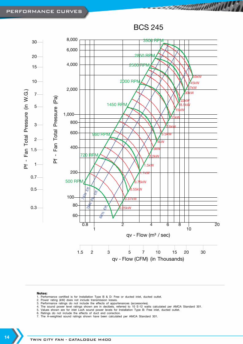
BCS 245
qv - Flow (CFM) (in Thousands)2 3 5 7 10 20 301.5 15
Pf - Fa
n To
tal Press
ure
(in W
.G.)
0.3
0.5
0.7
1
2
3
5
7
10
20
30
1.5
15
PERFORMANCE CURVES

WWW.TCF.COM 15
Notes:1. Performance certified is for Installation Type B & D: Free or ducted inlet, ducted outlet.2. Power rating (kW) does not include transmission losses.3. Performance ratings do not include the effects of appurtenances (accessories).4. The sound power level ratings shown are in decibels, referred to 10 E-12 watts calculated per AMCA Standard 301.5. Values shown are for inlet LwiA sound power levels for Installation Type B: Free inlet, ducted outlet.6. Ratings do not include the effects of duct end correction.7. The A-weighted sound ratings shown have been calculated per AMCA Standard 301.
12 4 6 8
1020
qv - Flow (m³ / sec)
80
100
200
400
600
800
1,000
2,000
4,000
6,000
8,000
10,000
Pf - Fa
n To
tal Press
ure
(Pa)
500 RPM
720 RPM
960 RPM
1450 RPM
2000 RPM
2500 RPM
2850 RPM
3500 RPM
0.37kW
0.55kW
0.75kW
1.1kW
1.5kW
2.2kW
3kW
4kW
5.5kW
7.5kW
11kW
15kW18.5kW22kW
30kW
37kW45kW55kW
75kW90kW
86% P
k. Eff.
82% Eff.
74% Eff.
BCS 270
qv - Flow (CFM) (in Thousands)3 5 7 10 20 3015
Pf - Fa
n To
tal Press
ure
(in W
.G.)
0.3
0.5
0.7
1
2
3
5
7
10
20
30
1.5
15
PERFORMANCE CURVES
TWIN CITY FAN - CATALOGUE M40016
Notes:1. Performance certified is for Installation Type B & D: Free or ducted inlet, ducted outlet.2. Power rating (kW) does not include transmission losses.3. Performance ratings do not include the effects of appurtenances (accessories).4. The sound power level ratings shown are in decibels, referred to 10 E-12 watts calculated per AMCA Standard 301.5. Values shown are for inlet LwiA sound power levels for Installation Type B: Free inlet, ducted outlet.6. Ratings do not include the effects of duct end correction.7. The A-weighted sound ratings shown have been calculated per AMCA Standard 301.
12 4 6 8
1020
qv - Flow (m³ / sec)
100
200
400
600
800
1,000
2,000
4,000
6,000
8,000
Pf - Fa
n To
tal Press
ure
(Pa)
500 RPM
720 RPM
960 RPM
1450 RPM
2000 RPM
2500 RPM
2850 RPM
0.55kW
0.75kW
1.1kW
1.5kW
2.2kW
3kW
4kW
5.5kW
7.5kW
11kW
15kW
18.5kW22kW
30kW
37kW
45kW
55kW
75kW
90kW
86% P
k. Eff.
82% Eff.
74% Eff.
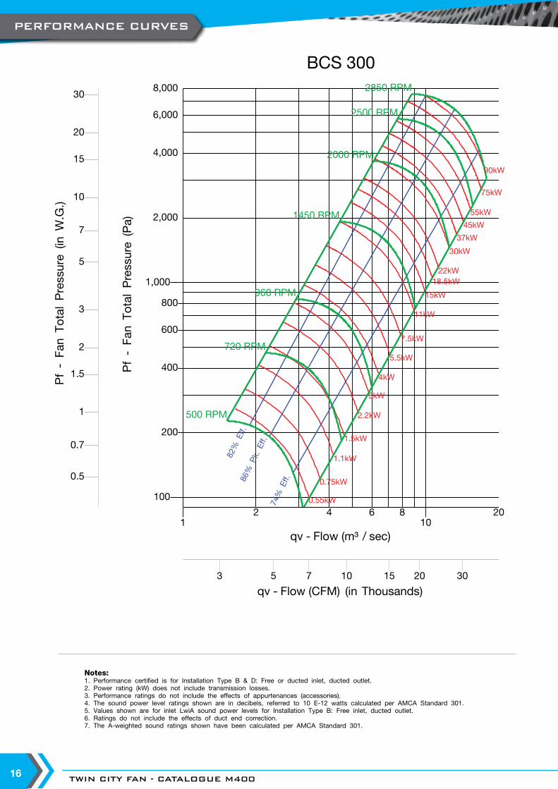
BCS 300
qv - Flow (CFM) (in Thousands)3 5 7 10 20 3015
Pf - Fa
n To
tal Press
ure
(in W
.G.)
0.5
0.7
1
2
3
5
7
10
20
30
1.5
15
PERFORMANCE CURVES

WWW.TCF.COM 17
Notes:1. Performance certified is for Installation Type B & D: Free or ducted inlet, ducted outlet.2. Power rating (kW) does not include transmission losses.3. Performance ratings do not include the effects of appurtenances (accessories).4. The sound power level ratings shown are in decibels, referred to 10 E-12 watts calculated per AMCA Standard 301.5. Values shown are for inlet LwiA sound power levels for Installation Type B: Free inlet, ducted outlet.6. Ratings do not include the effects of duct end correction.7. The A-weighted sound ratings shown have been calculated per AMCA Standard 301.
2 4 6 810
20
qv - Flow (m³ / sec)
100
200
400
600
800
1,000
2,000
4,000
6,000
8,000
10,000
Pf - Fa
n To
tal Press
ure
(Pa)
500 RPM
720 RPM
960 RPM
1450 RPM
2000 RPM
2500 RPM
2850 RPM
1.1kW
1.5kW
2.2kW
3kW
4kW
5.5kW
7.5kW
11kW
15kW
18.5kW22kW
30kW
37kW
45kW
55kW
75kW90kW
110kW132kW
86% P
k. Eff.
82% Eff.
74% Eff.
BCS 330
qv - Flow (CFM) (in Thousands)5 7 10 20 30 5015
Pf - Fa
n To
tal Press
ure
(in W
.G.)
0.5
0.7
1
2
3
5
7
10
20
30
1.5
15
PERFORMANCE CURVES

TWIN CITY FAN - CATALOGUE M40018
Notes:1. Performance certified is for Installation Type B & D: Free or ducted inlet, ducted outlet.2. Power rating (kW) does not include transmission losses.3. Performance ratings do not include the effects of appurtenances (accessories).4. The sound power level ratings shown are in decibels, referred to 10 E-12 watts calculated per AMCA Standard 301.5. Values shown are for inlet LwiA sound power levels for Installation Type B: Free inlet, ducted outlet.6. Ratings do not include the effects of duct end correction.7. The A-weighted sound ratings shown have been calculated per AMCA Standard 301.
12 4 6 8
1020
qv - Flow (m³ / sec)
40
60
80
100
200
400
600
800
1,000
2,000
4,000
6,000
8,000
10,000
Pf - Fa
n To
tal Pressure
(Pa)
300 RPM
500 RPM
720 RPM
960 RPM
1450 RPM
2000 RPM
2500 RPM
0.37kW
0.55kW
0.75kW
1.1kW
1.5kW
2.2kW
3kW
4kW
5.5kW
7.5kW
11kW
15kW18.5kW22kW
30kW37kW45kW55kW
75kW90kW110kW132kW
160kW
86% P
k. Eff.
82% Eff.
74% Eff.
BCS 365
qv - Flow (CFM) (in Thousands)3 5 7 10 20 30 5015
Pf - Fa
n To
tal Pressure
(in W
.G.)
0.2
0.3
0.5
0.7
1
2
3
5
7
10
20
30
1.5
15
PERFORMANCE CURVES

WWW.TCF.COM 19
Notes:1. Performance certified is for Installation Type B & D: Free or ducted inlet, ducted outlet.2. Power rating (kW) does not include transmission losses.3. Performance ratings do not include the effects of appurtenances (accessories).4. The sound power level ratings shown are in decibels, referred to 10 E-12 watts calculated per AMCA Standard 301.5. Values shown are for inlet LwiA sound power levels for Installation Type B: Free inlet, ducted outlet.6. Ratings do not include the effects of duct end correction.7. The A-weighted sound ratings shown have been calculated per AMCA Standard 301.
2 4 6 810
20 40
qv - Flow (m³ / sec)
60
80
100
200
400
600
800
1,000
2,000
4,000
6,000
Pf - Fa
n To
tal Press
ure
(Pa)
300 RPM
500 RPM
720 RPM
960 RPM
1450 RPM
2000 RPM
0.55kW
0.75kW
1.1kW
1.5kW
2.2kW
3kW
4kW
5.5kW
7.5kW
11kW
15kW
18.5kW22kW
30kW
37kW
45kW
55kW
75kW90kW
110kW
132kW
86% P
k. Eff.
82% Eff.
74% Eff.
BCS 402
qv - Flow (CFM) (in Thousands)5 7 10 20 30 50 7015
Pf - Fa
n To
tal Press
ure
(in W
.G.)
0.3
0.5
0.7
1
2
3
5
7
10
20
1.5
15
PERFORMANCE CURVES
TWIN CITY FAN - CATALOGUE M40020
Notes:1. Performance certified is for Installation Type B & D: Free or ducted inlet, ducted outlet.2. Power rating (kW) does not include transmission losses.3. Performance ratings do not include the effects of appurtenances (accessories).4. The sound power level ratings shown are in decibels, referred to 10 E-12 watts calculated per AMCA Standard 301.5. Values shown are for inlet LwiA sound power levels for Installation Type B: Free inlet, ducted outlet.6. Ratings do not include the effects of duct end correction.7. The A-weighted sound ratings shown have been calculated per AMCA Standard 301.
4 6 810
20 40
qv - Flow (m³ / sec)
80
100
200
400
600
800
1,000
2,000
4,000
6,000
8,000
10,000
Pf - Fa
n To
tal Press
ure
(Pa)
500 RPM
720 RPM
960 RPM
1450 RPM
2000 RPM
1.1kW
1.5kW
2.2kW
3kW
4kW
5.5kW
7.5kW
11kW
15kW
18.5kW22kW
30kW
37kW45kW55kW
75kW90kW110kW132kW160kW
86% P
k. Eff.
82% Eff.
74% Eff.
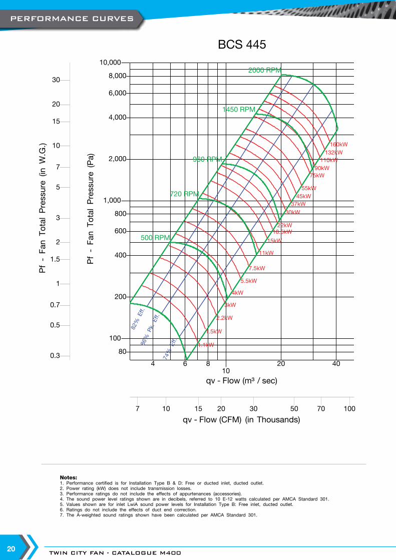
BCS 445
qv - Flow (CFM) (in Thousands)7 10 20 30 50 70 10015
Pf - Fa
n To
tal Press
ure
(in W
.G.)
0.3
0.5
0.7
1
2
3
5
7
10
20
30
1.5
15
PERFORMANCE CURVES
WWW.TCF.COM 21
Notes:1. Performance certified is for Installation Type B & D: Free or ducted inlet, ducted outlet.2. Power rating (kW) does not include transmission losses.3. Performance ratings do not include the effects of appurtenances (accessories).4. The sound power level ratings shown are in decibels, referred to 10 E-12 watts calculated per AMCA Standard 301.5. Values shown are for inlet LwiA sound power levels for Installation Type B: Free inlet, ducted outlet.6. Ratings do not include the effects of duct end correction.7. The A-weighted sound ratings shown have been calculated per AMCA Standard 301.
4 6 810
20 40 60
qv - Flow (m³ / sec)
80
100
200
400
600
800
1,000
2,000
4,000
6,000
8,000
10,000
20,000
Pf - Fa
n To
tal Press
ure
(Pa)
300 RPM
500 RPM
720 RPM
960 RPM
1450 RPM
2000 RPM
1.5kW
2.2kW
3kW
4kW
5.5kW
7.5kW
11kW
15kW18.5kW22kW
30kW37kW45kW55kW
75kW90kW110kW132kW160kW
86% P
k. Eff.
83% Eff.
75% Eff.
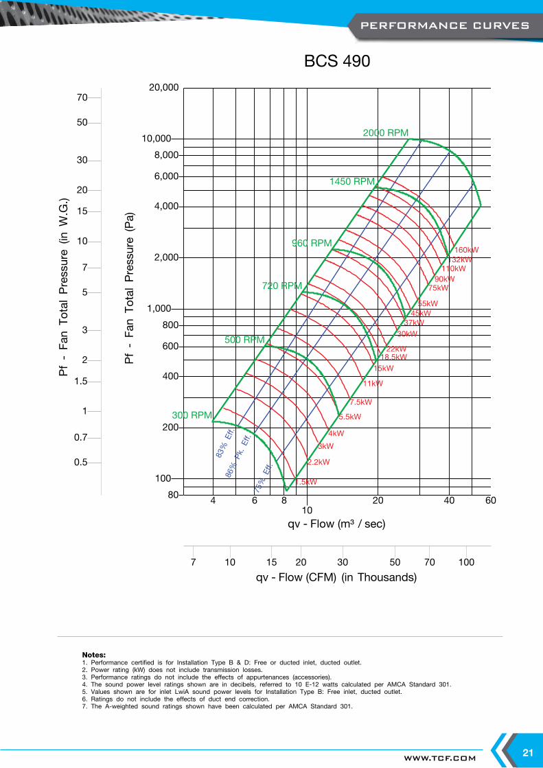
BCS 490
qv - Flow (CFM) (in Thousands)7 10 20 30 50 70 10015
Pf - Fa
n To
tal Press
ure
(in W
.G.)
0.5
0.7
1
2
3
5
7
10
20
30
50
70
1.5
15
PERFORMANCE CURVES

TWIN CITY FAN - CATALOGUE M40022
Notes:1. Performance certified is for Installation Type B & D: Free or ducted inlet, ducted outlet.2. Power rating (kW) does not include transmission losses.3. Performance ratings do not include the effects of appurtenances (accessories).4. The sound power level ratings shown are in decibels, referred to 10 E-12 watts calculated per AMCA Standard 301.5. Values shown are for inlet LwiA sound power levels for Installation Type B: Free inlet, ducted outlet.6. Ratings do not include the effects of duct end correction.7. The A-weighted sound ratings shown have been calculated per AMCA Standard 301.
4 6 810
20 40 60
qv - Flow (m³ / sec)
40
60
80
100
200
400
600
800
1,000
2,000
4,000
6,000
Pf - Fa
n To
tal Press
ure
(Pa)
200 RPM
300 RPM
500 RPM
720 RPM
960 RPM
1450 RPM
0.75kW
1.1kW
1.5kW
2.2kW
3kW
4kW
5.5kW
7.5kW
11kW
15kW18.5kW22kW
30kW37kW45kW
55kW
75kW90kW110kW132kW160kW
85% P
k. Eff.
82% Eff.
74% Eff.
BCS 542
qv - Flow (CFM) (in Thousands)7 10 20 30 50 70 10015
Pf - Fa
n To
tal Press
ure
(in W
.G.)
0.2
0.3
0.5
0.7
1
2
3
5
7
10
20
1.5
15
PERFORMANCE CURVES

WWW.TCF.COM 23
Notes:1. Performance certified is for Installation Type B & D: Free or ducted inlet, ducted outlet.2. Power rating (kW) does not include transmission losses.3. Performance ratings do not include the effects of appurtenances (accessories).4. The sound power level ratings shown are in decibels, referred to 10 E-12 watts calculated per AMCA Standard 301.5. Values shown are for inlet LwiA sound power levels for Installation Type B: Free inlet, ducted outlet.6. Ratings do not include the effects of duct end correction.7. The A-weighted sound ratings shown have been calculated per AMCA Standard 301.
4 6 810
20 40 60 80
qv - Flow (m³ / sec)
60
80
100
200
400
600
800
1,000
2,000
4,000
6,000
8,000
Pf - Fa
n To
tal Press
ure
(Pa)
200 RPM
300 RPM
500 RPM
720 RPM
960 RPM
1450 RPM
1.1kW
1.5kW
2.2kW
3kW
4kW
5.5kW
7.5kW
11kW
15kW18.5kW22kW
30kW
37kW45kW
55kW
75kW90kW110kW132kW160kW
86% P
k. Eff.
82% Eff.
74% Eff.
BCS 600
qv - Flow (CFM) (in Thousands)10 20 30 50 70 10015 150
Pf - Fa
n To
tal Press
ure
(in W
.G.)
0.3
0.5
0.7
1
2
3
5
7
10
20
30
1.5
15
PERFORMANCE CURVES

TWIN CITY FAN - CATALOGUE M40024
Notes:1. Performance certified is for Installation Type B & D: Free or ducted inlet, ducted outlet.2. Power rating (kW) does not include transmission losses.3. Performance ratings do not include the effects of appurtenances (accessories).4. The sound power level ratings shown are in decibels, referred to 10 E-12 watts calculated per AMCA Standard 301.5. Values shown are for inlet LwiA sound power levels for Installation Type B: Free inlet, ducted outlet.6. Ratings do not include the effects of duct end correction.7. The A-weighted sound ratings shown have been calculated per AMCA Standard 301.
6 810
20 40 60 80100
qv - Flow (m³ / sec)
70
100
300
500
700
1,000
3,000
5,000
7,000
10,000
Pf - Fa
n To
tal Press
ure
(Pa)
200 RPM
300 RPM
500 RPM
720 RPM
960 RPM
1450 RPM
2.2kW
3kW
4kW
5.5kW
7.5kW
11kW
15kW18.5kW22kW
30kW37kW45kW
55kW
75kW90kW110kW132kW160kW
86% P
k. Eff.
83% Eff.
74% Eff.
BCS 660
qv - Flow (CFM) (in Thousands)20 30 50 70 100 20015 150
Pf - Fa
n To
tal Press
ure
(in W
.G.)
0.3
0.5
0.7
1
2
3
5
7
10
20
30
1.5
15
PERFORMANCE CURVES
WWW.TCF.COM 25
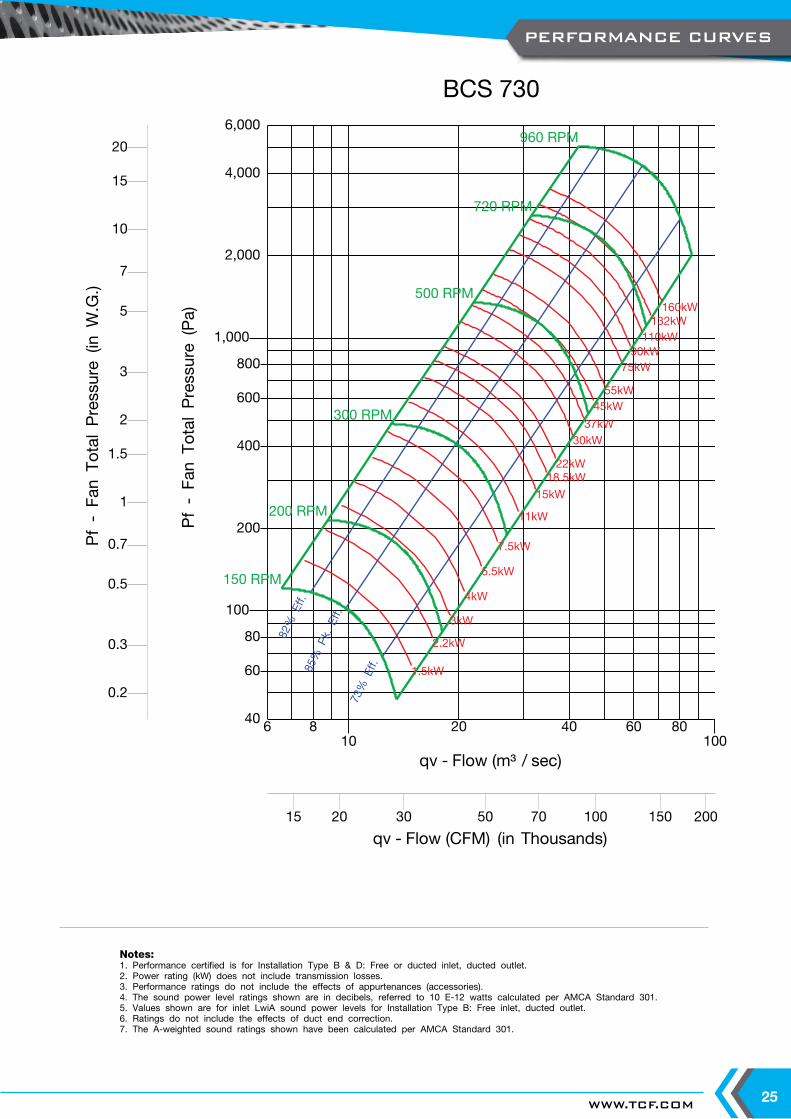
Notes:1. Performance certified is for Installation Type B & D: Free or ducted inlet, ducted outlet.2. Power rating (kW) does not include transmission losses.3. Performance ratings do not include the effects of appurtenances (accessories).4. The sound power level ratings shown are in decibels, referred to 10 E-12 watts calculated per AMCA Standard 301.5. Values shown are for inlet LwiA sound power levels for Installation Type B: Free inlet, ducted outlet.6. Ratings do not include the effects of duct end correction.7. The A-weighted sound ratings shown have been calculated per AMCA Standard 301.
6 810
20 40 60 80100
qv - Flow (m³ / sec)
40
60
80
100
200
400
600
800
1,000
2,000
4,000
6,000
Pf - Fa
n To
tal Press
ure
(Pa)
150 RPM
200 RPM
300 RPM
500 RPM
720 RPM
960 RPM
1.5kW
2.2kW
3kW
4kW
5.5kW
7.5kW
11kW
15kW
18.5kW22kW
30kW37kW
45kW55kW
75kW90kW110kW132kW160kW
85% P
k. Eff.
82% Eff.
73% Eff.
BCS 730
qv - Flow (CFM) (in Thousands)20 30 50 70 100 20015 150
Pf - Fa
n To
tal Press
ure
(in W
.G.)
0.2
0.3
0.5
0.7
1
2
3
5
7
10
20
1.5
15
PERFORMANCE CURVES
TWIN CITY FAN - CATALOGUE M40026
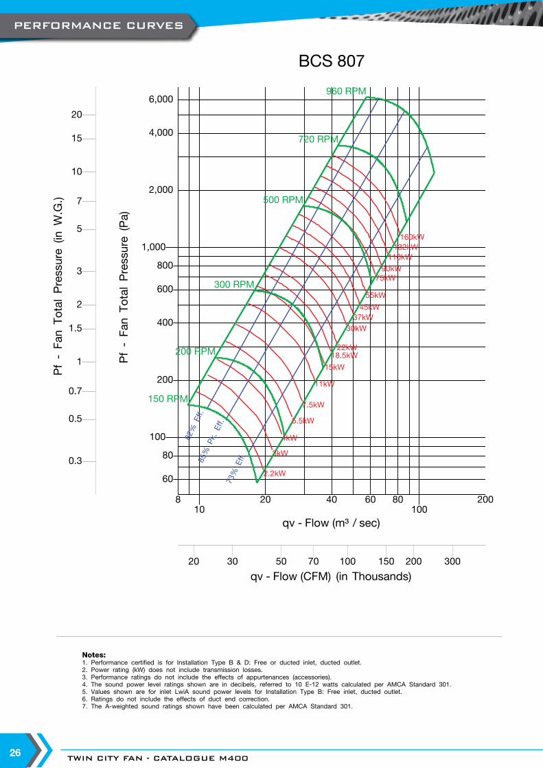
Notes:1. Performance certified is for Installation Type B & D: Free or ducted inlet, ducted outlet.2. Power rating (kW) does not include transmission losses.3. Performance ratings do not include the effects of appurtenances (accessories).4. The sound power level ratings shown are in decibels, referred to 10 E-12 watts calculated per AMCA Standard 301.5. Values shown are for inlet LwiA sound power levels for Installation Type B: Free inlet, ducted outlet.6. Ratings do not include the effects of duct end correction.7. The A-weighted sound ratings shown have been calculated per AMCA Standard 301.
810
20 40 60 80100
200
qv - Flow (m³ / sec)
60
80
100
200
400
600
800
1,000
2,000
4,000
6,000
Pf - Fa
n To
tal Press
ure
(Pa)
150 RPM
200 RPM
300 RPM
500 RPM
720 RPM
960 RPM
2.2kW
3kW
4kW
5.5kW
7.5kW
11kW
15kW
18.5kW22kW
30kW37kW45kW
55kW
75kW90kW
110kW132kW160kW
85% P
k. Eff.
82% Eff.
73% Eff.
BCS 807
qv - Flow (CFM) (in Thousands)20 30 50 70 100 200 300150
Pf - Fa
n To
tal Press
ure
(in W
.G.)
0.3
0.5
0.7
1
2
3
5
7
10
20
1.5
15
PERFORMANCE CURVES
WWW.TCF.COM 27
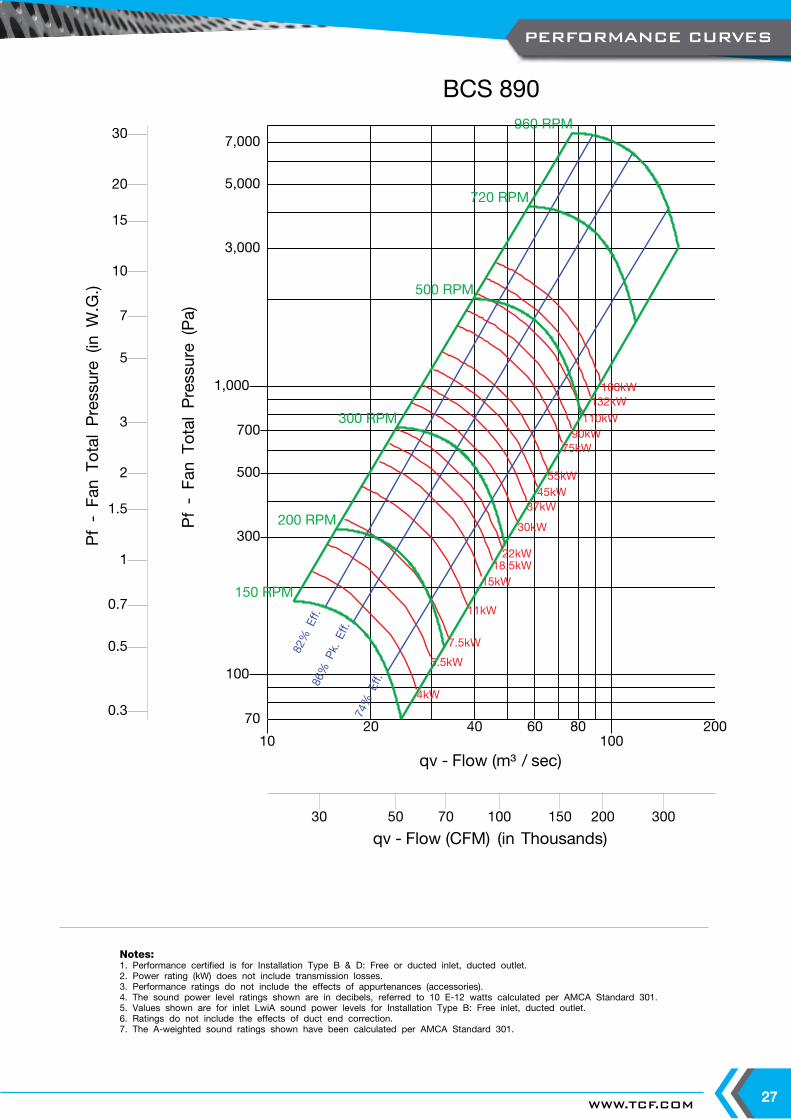
Notes:1. Performance certified is for Installation Type B & D: Free or ducted inlet, ducted outlet.2. Power rating (kW) does not include transmission losses.3. Performance ratings do not include the effects of appurtenances (accessories).4. The sound power level ratings shown are in decibels, referred to 10 E-12 watts calculated per AMCA Standard 301.5. Values shown are for inlet LwiA sound power levels for Installation Type B: Free inlet, ducted outlet.6. Ratings do not include the effects of duct end correction.7. The A-weighted sound ratings shown have been calculated per AMCA Standard 301.
1020 40 60 80
100200
qv - Flow (m³ / sec)
70
100
300
500
700
1,000
3,000
5,000
7,000
Pf - Fa
n To
tal Press
ure
(Pa)
150 RPM
200 RPM
300 RPM
500 RPM
720 RPM
960 RPM
4kW
5.5kW
7.5kW
11kW
15kW18.5kW22kW
30kW
37kW45kW55kW
75kW90kW110kW
132kW160kW
86% P
k. Eff.
82% Eff.
74% Eff.
BCS 890
qv - Flow (CFM) (in Thousands)30 50 70 100 200 300150
Pf - Fa
n To
tal Press
ure
(in W
.G.)
0.3
0.5
0.7
1
2
3
5
7
10
20
30
1.5
15
PERFORMANCE CURVES
TWIN CITY FAN - CATALOGUE M40028
HE HA
HQ
DC
GCG
HC
Q
P J
KL
C
KS
CW THD
N
SE
SD GB
DX
GAGA. SIDES
DISCH.FLANGE
KWYSIZE
DIA. SHAFTGA. SCROLL
BABASE ANGLES
DISCH
CL OUTS
IDE
HOUSING
OUTSIDEHOUSING
O.D.
INLE
T
H
K
K
M
BHL
M
DIA. BASEHOLES
FAN HSGCL
FOUNDATION PLAN(FOR DBD SEE NOTE 1)
MOTOR LOCATION ‘L’ (LEFT) SHOWN
FAN S
HAFT
C L
CW DBDCW TAU CW UBD CW BAU CW BHD
J
HGHP
HE HB
DA DD
HHHD
G
HQHC HG
HA
G
HB HF
HH
DF
HA
HG
DG
G
DE
DISCH
C L
NOTE 2
WITH OPTIONALFLANGED INLET
G
HE
MOTOR(ARR 9 ONLY)SEE NOTE 5
A
B
AHDBD ONLY
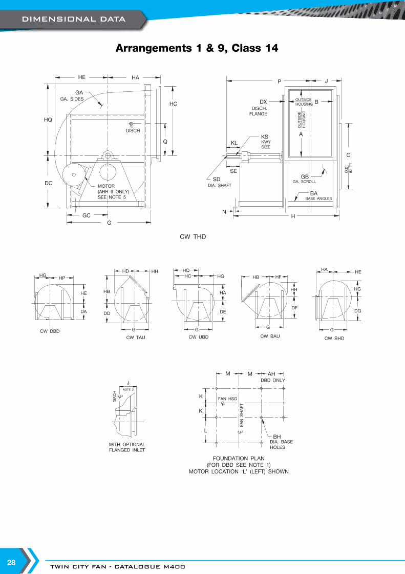
Arrangements 1 & 9, Class 14
DIMENSIONAL DATA

WWW.TCF.COM 29
SIZE A AH B BA BH CDA DC DD DE DF
ARR 1 ARR 9 ARR 1 ARR 9 ARR 1 ARR 9 ARR 1 ARR 9ARR 1 ARR 9
SEE NOTE 4165 443 248 335 38 x 50 11 451 334 508 343 508 368 508 387 508 413 508182 492 275 370 38 x 50 11 495 368 584 375 584 400 584 425 584 451 584200 538 295 405 38 x 50 14 543 402 584 413 584 438 584 464 584 489 584222 598 327 449 50 x 50 14 603 449 584 457 584 489 584 521 584 559 584245 659 359 494 50 x 50 14 662 495 584 508 584 540 584 572 584 610 584270 727 395 543 50 x 50 14 724 545 660 559 660 597 660 629 660 667 660300 808 438 605 65 x 65 14 803 679 679 679 679 679 679 724 724 762 762330 892 484 662 65 x 65 14 883 762 762 762 762 762 762 787 787 832 832365 983 537 734 65 x 65 14 978 737 737 749 749 800 800 851 851 902 902402 1083 592 808 75 x 75 21 1078 813 813 838 838 895 895 940 940 1003 1003445 1197 656 894 75 x 75 21 1191 899 899 902 902 978 978 1016 1016 1099 1099490 1319 715 981 75 x 75 21 1311 991 991 991 991 1073 1073 1118 1118 1207 1207542 1457 808 1089 75 x 100 21 1451 1094 1094 1105 1105 1181 1181 1245 1245 1327 1327600 1613 887 1202 75 x 100 21 1604 1211 1211 1219 1219 1302 1302 1372 1372 1461 1461660 1770 994 1326 90 x 125 21 1762 1332 1332 1334 1334 1416 1416 1499 1499 1600 1600730 1962 1083 1462 90 x 125 21 1949 1473 1473 1448 1448 1568 1568 1638 1638 1765 1765807 2170 1195 1616 90 x 125 21 2156 1630 1630 1600 1600 1715 1715 1829 1829 1943 1943890 2391 1276 1781 90 x 125 21 2372 1778 1778 1759 1759 1873 1873 1988 1988 2159 2159
AC17014D
NOTES:1. Punched outlet flanges are included on all discharges per AC14987, or for 'DBD' AC14868.2. Optional punched inlet per AS363.3. 'CW' rotation is shown. 'CCW' rotation is similar but opposite.4. For fans with inlet box at 90o or 270o use 'BAU' discharge dimension 'DF' for centerline height.5. 'FR' equals maximum motor frame.
SIZEDG
DXFR
ARR 9G GA GB GC
HHA HB HC HD HE HF HG
ARR 1 ARR 9 ARR 1 ARR 9165 495 508 25 x 25 132M 616 2 2 308 743 930 334 565 467 383 359 338 318182 559 584 32 x 32 160M 660 2.5 2 330 803 1076 368 630 522 424 399 375 351200 610 584 32 x 32 160M 711 2.5 2 356 864 1111 402 686 568 467 440 413 386222 673 648 32 x 32 160L 794 2.5 2 397 972 1149 449 762 629 519 484 456 427245 730 711 32 x 32 160L 851 2.5 2 425 1054 1194 495 838 689 568 533 502 470270 800 775 38 x 38 180M 914 2.5 2 457 1153 1314 545 926 764 627 589 554 519300 902 902 38 x 38 180L 1041 3 2.5 521 1416 1416 605 1024 845 697 654 616 578330 991 991 38 x 38 200M 1118 3 2.5 559 1540 1540 667 1129 929 765 721 678 635365 1041 1041 38 x 38 200M 1219 3 2.5 610 1610 1610 737 1242 1019 851 800 753 705402 1156 1156 38 x 38 200L 1334 3 2.5 667 1724 1724 813 1367 1119 940 881 829 776445 1270 1270 38 x 38 225S 1435 3 2.5 718 1851 1851 899 1508 1233 1038 972 914 857490 1391 1391 50 x 50 225S 1562 3 2.5 781 1946 1946 991 1669 1369 1140 1072 1008 945542 1530 1530 50 x 50 250M 1702 3 2.5 851 2223 2223 1094 1838 1506 1264 1186 1116 1046600 1683 1683 50 x 50 250M 1854 3 2.5 927 2330 2330 1211 2032 1662 1397 1313 1235 1157660 1861 1861 65 x 65 250M 2032 3 2.5 1016 2572 2572 1332 2237 1832 1534 1443 1356 1268730 2051 2051 65 x 65 250M 2235 3 3 1118 2785 2785 1473 2472 2023 1700 1597 1502 1407807 2261 2261 65 x 65 250M 2426 3 3 1213 3013 3013 1630 2731 2230 1880 1765 1661 1556890 2483 2483 65 x 65 250M 2705 5 3 1353 3255 3255 1778 2991 2451 2072 1946 1830 1715
SIZE HH HP HQ J K KL KSL
M NP
Q SD SEARR 1 ARR 9 ARR 1 ARR 9
165 297 492 – 226 191 76 8 x 7 318 505 222 22 568 756 221 30 95182 327 541 – 245 208 89 10 x 8 343 616 245 22 624 897 245 38 108200 359 588 – 260 226 89 10 x 8 368 616 270 22 667 914 268 38 108222 399 648 – 305 254 102 14 x 9 419 597 298 22 765 943 298 46 121245 438 708 – 327 276 114 14 x 9 457 597 327 22 838 978 329 50 133270 484 776 – 351 300 114 14 x 9 508 670 359 22 913 1075 362 50 133300 540 870 – 394 338 127 16 x 10 683 683 403 29 1132 1132 402 55 146330 592 954 – 422 367 127 16 x 10 749 749 441 29 1227 1227 445 55 146365 657 1045 – 457 402 127 18 x 11 749 749 480 29 1262 1262 489 65 146402 724 1157 – 508 446 127 18 x 11 762 762 530 35 1313 1313 540 65 146445 800 1272 – 551 489 140 20 x 12 803 803 581 35 1410 1410 597 70 159490 881 1394 – 594 532 140 20 x 12 813 813 645 35 1462 1462 657 75 159542 976 1557 1518 673 598 152 25 x 14 930 930 702 48 1646 1646 727 90 171600 1080 1713 1670 730 656 152 25 x 14 924 924 778 48 1697 1697 805 90 171660 1181 1896 1835 818 730 178 28 x 16 991 991 842 60 1851 1851 883 100 197730 1311 2086 2026 887 799 191 28 x 16 1067 1067 943 60 2008 2008 978 100 210807 1451 2294 2229 960 875 203 32 x 18 1143 1143 1038 60 2180 2180 1083 115 229890 1599 2515 2451 1043 957 203 32 x 18 1219 1219 1178 60 2338 2338 1192 125 229
DIMENSIONAL DATA

TWIN CITY FAN - CATALOGUE M40030
HE HA
HQ
DC
GC
GD
HC
Q
P J
KLC
KS
CW THD
N
SESD
GB
BDX
GAGA. SIDES
DISCH.FLANGE
KWYSIZE
DIA. SHAFTGA. SCROLL
BABASE ANGLES
DISCH
CL OUTS
IDE
HOUSING
A
OUTSIDEHOUSING
O.D.
INLE
T
H
NOTE 1
K
K
M
BHL
M
DIA. BASEHOLES
FAN HSGCL
FOUNDATION PLAN(FOR DBD SEE NOTE 1)
FAN S
HAFT
C L
CW DBD CW TAU CW UBD CW BAU CW BHD
J
HGHP
HE HB
DA DD
HHHD
G
HQHC HG
HA
G G
HB HF
HH
DF
HA
HG
DG
GD
HE
DISCH
C L
NOTE 2
WITH OPTIONALFLANGED INLET
G
HE
NOTE 5
Arrangements 1 & 9, Class 17
DIMENSIONAL DATA

WWW.TCF.COM 31
SIZE A B BA BH CDA DC DD DE
DF DGARR 1 ARR 9 ARR 1 ARR 9 ARR 1 ARR 9 ARR 1 ARR 9
SEE NOTE 4 FOR ARRANGEMENT 1 ARR 1 ARR 9 ARR 1 ARR 9165 446 338 38 x 50 11 451 334 603 343 603 368 603 387 603 413 603 495 603182 495 372 50 x 50 14 495 368 667 375 667 400 667 425 667 451 667 559 667200 541 406 50 x 50 14 543 402 749 413 749 438 749 464 749 489 749 610 749222 602 451 65 x 65 14 603 449 762 457 762 489 762 521 762 559 762 673 762245 665 499 65 x 65 14 662 495 768 508 768 540 768 572 768 610 768 730 768270 734 548 65 x 65 14 724 545 838 559 838 597 838 629 838 667 838 800 838300 813 608 75 x 75 21 803 605 851 622 851 660 851 699 851 749 851 883 883330 897 665 75 x 75 21 883 667 959 686 959 724 959 762 959 819 959 959 959365 988 737 75 x 75 21 978 737 959 749 959 800 959 851 959 902 959 1054 1054402 1087 811 75 x 100 21 1078 813 1022 838 1022 895 1022 940 1022 1003 1022 1156 1156445 1202 897 75 x 100 21 1191 899 1041 902 1041 978 1041 1016 1041 1099 1099 1270 1270490 1324 984 75 x 100 21 1311 991 1041 991 1041 1073 1073 1118 1118 1207 1207 1391 1391542 1462 1092 90 x 125 21 1451 1094 1094 1105 1105 1181 1181 1245 1245 1327 1327 1543 1543600 1618 1205 90 x 125 21 1604 1211 1211 1219 1219 1302 1302 1372 1372 1461 1461 1695 1695660 1775 1329 100 x 150 21 1762 1332 1332 1334 1334 1416 1416 1499 1499 1600 1600 1873 1873730 1965 1465 100 x 150 21 1949 1473 1473 1448 1448 1568 1568 1638 1638 1765 1765 2064 2064807 2173 1619 100 x 150 21 2156 1630 1630 1600 1600 1715 1715 1829 1829 1943 1943 2273 2273890 2394 1781 100 x 150 21 2372 1778 1778 1759 1759 1873 1873 1988 1988 2159 2159 2496 2496
BC14952E – ARR. 1BC14955D – ARR. 9
NOTES:1. Punched outlet flanges are included on all discharges per AC14987, or for 'DBD' AC14868.2. Optional punched inlet per AS363.3. 'CW' rotation is shown. 'CCW' rotation is similar but opposite.4. For fans with inlet box at 90o or 270o use 'BAU' discharge dimension 'DF' for centerline height.5. 'FR' equals maximum motor frame.
SIZE DXFR
ARR 9G GA GB GC GD
HHA HB HC HD HE HF HG HH HP
ARR 1 ARR 9165 32 x 32 160L 616 3 3 308 588 708 1045 334 572 475 384 360 340 319 298 494182 32 x 32 180L 686 3 3 343 686 765 1134 368 630 524 425 400 376 353 329 543200 32 x 32 200L 737 3 3 368 737 826 1207 402 687 570 467 441 414 387 360 589222 32 x 32 200L 819 3 3 410 819 946 1276 449 764 630 521 486 457 429 400 662245 38 x 38 200L 876 5 5 438 876 1032 1324 495 845 699 572 537 505 473 441 724270 38 x 38 225M 940 5 5 470 940 1134 1403 545 927 767 630 592 557 522 487 792300 38 x 38 225M 1067 5 5 533 1067 1257 1489 605 1026 846 699 656 617 579 541 884330 38 x 38 250M 1143 5 5 572 1143 1365 1718 667 1129 930 767 722 679 637 594 969365 38 x 38 250M 1245 5 5 622 1245 1473 1788 737 1243 1021 854 802 754 706 659 1059402 50 x 50 250M 1334 5 5 667 1334 1626 2061 813 1376 1134 941 883 830 778 725 1184445 50 x 50 250M 1435 5 5 718 1435 1788 2146 899 1518 1248 1041 973 916 859 802 1299490 50 x 50 250M 1562 5 5 781 1562 1924 2232 991 1669 1370 1141 1073 1010 946 883 1421542 65 x 65 250M 1702 5 5 851 1702 2083 2381 1094 1849 1521 1267 1187 1118 1048 978 1584600 65 x 65 250M 1880 5 5 940 1880 2273 2496 1211 2042 1676 1399 1314 1237 1159 1081 1740660 65 x 65 250M 2032 5 5 1016 2032 2499 2670 1332 2239 1834 1537 1445 1357 1270 1183 1923730 65 x 65 250M 2235 5 5 1118 2235 2711 2807 1473 2473 2024 1702 1599 1503 1408 1313 2113807 65 x 65 250M 2451 5 5 1226 2451 2940 2959 1630 2731 2232 1883 1767 1662 1557 1453 2321890 65 x 65 250M 2731 5 5 1365 2731 3178 3121 1778 2991 2453 2073 1948 1832 1716 1600 2542
SIZE HQ J KKL
KSL
M NP
Q SDSE
ARR 1 ARR 9 ARR 1 ARR 9 ARR 1 ARR 9 ARR 1 ARR 9165 – 246 198 89 108 14 x 9 241 578 222 22 589 945 221 46 102 121182 – 262 214 114 127 14 x 9 267 635 245 22 656 1037 245 46 127 140200 – 279 232 114 152 14 x 9 292 673 270 22 699 1124 268 50 127 171222 – 314 260 127 152 14 x 9 349 679 292 29 797 1159 298 50 140 171245 – 338 284 152 152 16 x 10 387 679 321 29 884 1183 329 55 165 171270 – 363 310 152 165 16 x 10 438 708 353 29 960 1243 362 55 165 178300 – 406 346 178 165 18 x 11 483 715 397 35 1073 1286 402 65 197 178330 – 435 375 178 191 18 x 11 533 886 435 35 1153 1511 445 65 197 203365 – 470 410 178 191 20 x 12 572 886 473 35 1226 1546 489 70 197 203402 – 533 461 203 191 20 x 12 610 1045 518 48 1340 1756 540 75 222 203445 – 576 503 203 191 25 x 14 686 1045 568 48 1465 1799 597 90 229 203490 – 619 546 229 191 28 x 16 737 1045 632 48 1584 1842 657 100 254 203542 1518 699 613 229 191 28 x 16 749 1048 689 60 1664 1911 727 100 254 203600 1683 756 670 241 191 28 x 16 826 1048 765 60 1810 1969 805 100 267 203660 1838 843 744 254 191 28 x 16 889 1060 829 73 1961 2056 883 100 279 203730 2026 911 813 267 191 32 x 18 965 1060 930 73 2118 2124 978 115 292 203807 2245 988 889 267 191 32 x 18 1041 1060 1026 73 2270 2200 1083 125 292 203890 2464 1068 970 279 191 32 x 18 1118 1060 1165 73 2440 2281 1192 125 305 203
DIMENSIONAL DATA

TWIN CITY FAN - CATALOGUE M40032
HE HA
HQ
DC
GC
G
HC
Q
P J
KLC
KS
CW THD
N
SE
SDGB
BDX
GAGA. SIDES
DISCH.FLANGE
KWYSIZE
DIA. SHAFTGA. SCROLL
BABASE ANGLES
DISCH
CL OUTS
IDE
HOUSING
A
OUTSIDEHOUSING
O.D.
INLE
T
H
NOTE 1
K
K
M
BHL
M
DIA. BASEHOLES
FAN HSGCL
FOUNDATION PLAN(FOR DBD SEE NOTE 1)
FAN S
HAFT
C L
CW DBD CW TAU CW UBD CW BAUCW BHD
J
HGHP
HE HB
DA DD
HHHD
G
HQHC HG
HA
G G
HB HF
HH
DF
HA
HG
DG
G
DE
DISCH
C L
NOTE 2
WITH OPTIONALFLANGED INLET
G
HE
NOTE 5
Arrangements 1 (Sizes 222-890) & 9 (Sizes 222-542), Class 22
DIMENSIONAL DATA
WWW.TCF.COM 33
SIZE A B BA BH CDA DC DD DE
DF DGARR 1 ARR 9 ARR 1 ARR 9 ARR 1 ARR 9 ARR 1 ARR 9
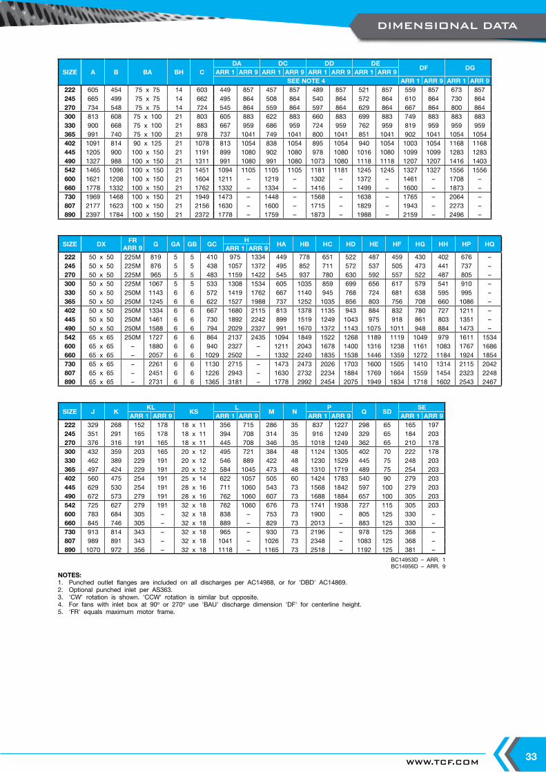
SEE NOTE 4 ARR 1 ARR 9 ARR 1 ARR 9222 605 454 75 x 75 14 603 449 857 457 857 489 857 521 857 559 857 673 857245 665 499 75 x 75 14 662 495 864 508 864 540 864 572 864 610 864 730 864270 734 548 75 x 75 14 724 545 864 559 864 597 864 629 864 667 864 800 864300 813 608 75 x 100 21 803 605 883 622 883 660 883 699 883 749 883 883 883330 900 668 75 x 100 21 883 667 959 686 959 724 959 762 959 819 959 959 959365 991 740 75 x 100 21 978 737 1041 749 1041 800 1041 851 1041 902 1041 1054 1054402 1091 814 90 x 125 21 1078 813 1054 838 1054 895 1054 940 1054 1003 1054 1168 1168445 1205 900 100 x 150 21 1191 899 1080 902 1080 978 1080 1016 1080 1099 1099 1283 1283490 1327 988 100 x 150 21 1311 991 1080 991 1080 1073 1080 1118 1118 1207 1207 1416 1403542 1465 1096 100 x 150 21 1451 1094 1105 1105 1105 1181 1181 1245 1245 1327 1327 1556 1556600 1621 1208 100 x 150 21 1604 1211 – 1219 – 1302 – 1372 – 1461 – 1708 –660 1778 1332 100 x 150 21 1762 1332 – 1334 – 1416 – 1499 – 1600 – 1873 –730 1969 1468 100 x 150 21 1949 1473 – 1448 – 1568 – 1638 – 1765 – 2064 –807 2177 1623 100 x 150 21 2156 1630 – 1600 – 1715 – 1829 – 1943 – 2273 –890 2397 1784 100 x 150 21 2372 1778 – 1759 – 1873 – 1988 – 2159 – 2496 –
BC14953D – ARR. 1BC14956D – ARR. 9
NOTES:1. Punched outlet flanges are included on all discharges per AC14988, or for 'DBD' AC14869.2. Optional punched inlet per AS363.3. 'CW' rotation is shown. 'CCW' rotation is similar but opposite.4. For fans with inlet box at 90o or 270o use 'BAU' discharge dimension 'DF' for centerline height.5. 'FR' equals maximum motor frame.
SIZE DXFR
ARR 9G GA GB GC
HHA HB HC HD HE HF HG HH HP HQ
ARR 1 ARR 9222 50 x 50 225M 819 5 5 410 975 1334 449 778 651 522 487 459 430 402 676 –245 50 x 50 225M 876 5 5 438 1057 1372 495 852 711 572 537 505 473 441 737 –270 50 x 50 225M 965 5 5 483 1159 1422 545 937 780 630 592 557 522 487 805 –300 50 x 50 225M 1067 5 5 533 1308 1534 605 1035 859 699 656 617 579 541 910 –330 50 x 50 250M 1143 6 6 572 1419 1762 667 1140 945 768 724 681 638 595 995 –365 50 x 50 250M 1245 6 6 622 1527 1988 737 1252 1035 856 803 756 708 660 1086 –402 50 x 50 250M 1334 6 6 667 1680 2115 813 1378 1135 943 884 832 780 727 1211 –445 50 x 50 250M 1461 6 6 730 1892 2242 899 1519 1249 1043 975 918 861 803 1351 –490 50 x 50 250M 1588 6 6 794 2029 2327 991 1670 1372 1143 1075 1011 948 884 1473 –542 65 x 65 250M 1727 6 6 864 2137 2435 1094 1849 1522 1268 1189 1119 1049 979 1611 1534600 65 x 65 – 1880 6 6 940 2327 – 1211 2043 1678 1400 1316 1238 1161 1083 1767 1686660 65 x 65 – 2057 6 6 1029 2502 – 1332 2240 1835 1538 1446 1359 1272 1184 1924 1854730 65 x 65 – 2261 6 6 1130 2715 – 1473 2473 2026 1703 1600 1505 1410 1314 2115 2042807 65 x 65 – 2451 6 6 1226 2943 – 1630 2732 2234 1884 1769 1664 1559 1454 2323 2248890 65 x 65 – 2731 6 6 1365 3181 – 1778 2992 2454 2075 1949 1834 1718 1602 2543 2467
SIZE J KKL
KSL
M NP
Q SDSE
ARR 1 ARR 9 ARR 1 ARR 9 ARR 1 ARR 9 ARR 1 ARR 9222 329 268 152 178 18 x 11 356 715 286 35 837 1227 298 65 165 197245 351 291 165 178 18 x 11 394 708 314 35 916 1249 329 65 184 203270 376 316 191 165 18 x 11 445 708 346 35 1018 1249 362 65 210 178300 432 359 203 165 20 x 12 495 721 384 48 1124 1305 402 70 222 178330 462 389 229 191 20 x 12 546 889 422 48 1230 1529 445 75 248 203365 497 424 229 191 20 x 12 584 1045 473 48 1310 1719 489 75 254 203402 560 475 254 191 25 x 14 622 1057 505 60 1424 1783 540 90 279 203445 629 530 254 191 28 x 16 711 1060 543 73 1568 1842 597 100 279 203490 672 573 279 191 28 x 16 762 1060 607 73 1688 1884 657 100 305 203542 725 627 279 191 32 x 18 762 1060 676 73 1741 1938 727 115 305 203600 783 684 305 – 32 x 18 838 – 753 73 1900 – 805 125 330 –660 845 746 305 – 32 x 18 889 – 829 73 2013 – 883 125 330 –730 913 814 343 – 32 x 18 965 – 930 73 2196 – 978 125 368 –807 989 891 343 – 32 x 18 1041 – 1026 73 2348 – 1083 125 368 –890 1070 972 356 – 32 x 18 1118 – 1165 73 2518 – 1192 125 381 –
DIMENSIONAL DATA
TWIN CITY FAN - CATALOGUE M40034
HE HA
HQ
DC
GC
G
HC
Q
P J
KL
C
KS
CW THD
N
SE
SDGB
BDX
GAGA. SIDES
DISCH.FLANGE
KWYSIZE
DIA. SHAFTGA. SCROLL
BABASE ANGLES
DISCH
CL OUTS
IDE
HOUSING
A
OUTSIDEHOUSING
O.D.
INLE
T
H
NOTE 1
K
K
M
BHL
M
DIA. BASEHOLES
FAN HSGCL
FOUNDATION PLAN(FOR DBD SEE NOTE 1)
FAN S
HAFT
C L
CW DBD CW TAU CW UBD CW BAU CW BHD
J
HG HP
HE HB
DA DD
HHHDHQHC HG
HA
HB HF
HH
DF
HA
HG
DGHE
DISCH
C L
NOTE 2
WITH OPTIONALFLANGED INLET
HE
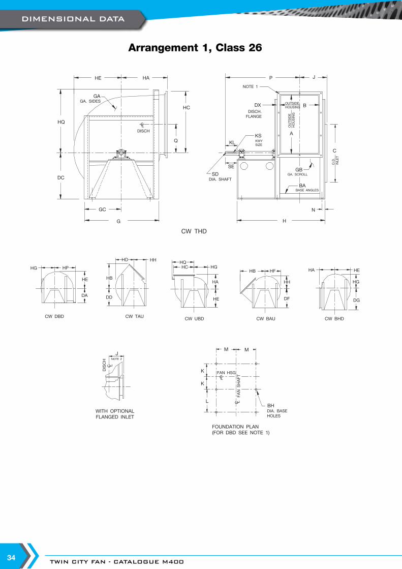
Arrangement 1, Class 26
DIMENSIONAL DATA
WWW.TCF.COM 35
SIZE A B BA BH CDA DC DD DE
DF DG DX G GASEE NOTE 4
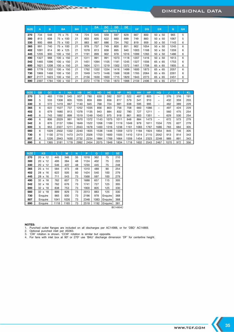
270 734 548 75 x 75 14 724 545 559 597 629 667 800 50 x 50 965 5300 813 608 75 x 100 21 803 605 622 660 699 749 883 50 x 50 1067 5330 900 668 75 x 100 21 883 667 686 724 762 819 959 50 x 50 1143 6365 991 740 75 x 100 21 978 737 749 800 851 902 1054 50 x 50 1245 6402 1091 814 90 x 125 21 1078 813 838 895 940 1003 1168 50 x 50 1359 6445 1205 900 100 x 150 21 1191 899 902 978 1016 1099 1283 50 x 50 1486 6490 1327 988 100 x 150 21 1311 991 991 1073 1118 1207 1416 50 x 50 1613 6542 1465 1096 100 x 150 21 1451 1094 1105 1181 1245 1327 1556 65 x 65 1753 6600 1621 1208 100 x 150 21 1604 1211 1219 1302 1372 1461 1708 65 x 65 1905 6660 1778 1332 100 x 150 21 1762 1332 1334 1416 1499 1600 1873 65 x 65 2057 6730 1969 1468 100 x 150 21 1949 1473 1448 1568 1638 1765 2064 65 x 65 2261 6807 2177 1623 100 x 150 21 2156 1630 1600 1715 1829 1943 2273 65 x 65 2451 6890 2397 1784 100 x 150 21 2372 1778 1759 1873 1988 2159 2496 65 x 65 2731 6
NOTES:1. Punched outlet flanges are included on all discharges per AC14988, or for 'DBD' AC14869.2. Optional punched inlet per AS363.3. 'CW' rotation is shown. 'CCW' rotation is similar but opposite.4. For fans with inlet box at 90o or 270o use 'BAU' discharge dimension 'DF' for centerline height.
SIZE GB GC H HA HB HC HD HE HF HG HH HP HQ J K KL270 5 483 1159 545 937 780 630 592 557 522 487 805 – 376 316 191300 5 533 1308 605 1035 859 699 656 617 579 541 910 – 432 359 203330 6 572 1419 667 1140 945 768 724 681 638 595 995 – 462 389 229365 6 622 1527 737 1252 1035 856 803 756 708 660 1086 – 497 424 229402 6 679 1680 813 1378 1135 943 884 832 780 727 1211 – 560 475 254445 6 743 1892 899 1519 1249 1043 975 918 861 803 1351 – 629 530 254490 6 806 2029 991 1670 1372 1143 1075 1011 948 884 1473 – 672 573 279542 6 876 2137 1094 1849 1522 1268 1189 1119 1049 979 1611 1534 725 627 279600 6 953 2327 1211 2043 1678 1400 1316 1238 1161 1083 1767 1686 783 684 305660 6 1029 2502 1332 2240 1835 1538 1446 1359 1272 1184 1924 1854 845 746 305730 6 1130 2715 1473 2473 2026 1703 1600 1505 1410 1314 2115 2042 913 814 343807 6 1226 2943 1630 2732 2234 1884 1769 1664 1559 1454 2323 2248 989 891 343890 6 1365 3181 1778 2992 2454 2075 1949 1834 1718 1602 2543 2467 1070 972 356
BC14954C
SIZE KS L M N P Q SD SE270 20 x 12 445 346 35 1018 362 75 210300 20 x 12 495 384 48 1124 402 75 222330 20 x 12 546 422 48 1230 445 75 248365 25 x 14 584 473 48 1310 489 90 254402 28 x 16 622 505 60 1424 540 100 279445 28 x 16 711 543 73 1568 597 100 279490 32 x 18 762 607 73 1688 657 115 305542 32 x 18 762 676 73 1741 727 125 305600 32 x 18 838 753 73 1900 805 125 330660 32 x 18 889 829 73 2013 883 125 330730 Enquire 965 930 73 2196 978 Enquire 368807 Enquire 1041 1026 73 2348 1083 Enquire 368890 Enquire 1118 1165 73 2518 1192 Enquire 381
DIMENSIONAL DATA

TWIN CITY FAN - CATALOGUE M40036
HE HA
HQ
DC
GCG
HC
Q
P J
KL
C
KS
N
SE
SD GB
DX
GAGA. SIDES
DISCH.FLANGE
KWYSIZE
DIA. SHAFTGA. SCROLL
BABASE ANGLES
DISCHCL
OUTS
IDE
HOUSING
OUTSIDEHOUSING
O.D.
INLE
T
K
K
M
BHL
M
DIA. BASEHOLES
FAN HSGCL
FOUNDATION PLAN(FOR DBD SEE NOTE 1)
MOTOR LOCATION ‘L’ (LEFT) SHOWN
FAN S
HAFT
C L
CW DBD
CW TAU CW UBDCW BAU
CW BHD
J
HGHP
HE HB
DA DD
HHHD
G
HQHC HG
HA
G
HB HF
HH
DF
HA
HG
DG
G
DE
DISCH
C L
NOTE 2
WITH OPTIONALFLANGED INLET
G
HE
NOTE 3
B
AHDBD ONLY
VH
A
T
S
CW THD
Arrangements 9F, Class 14
DIMENSIONAL DATA
WWW.TCF.COM 37
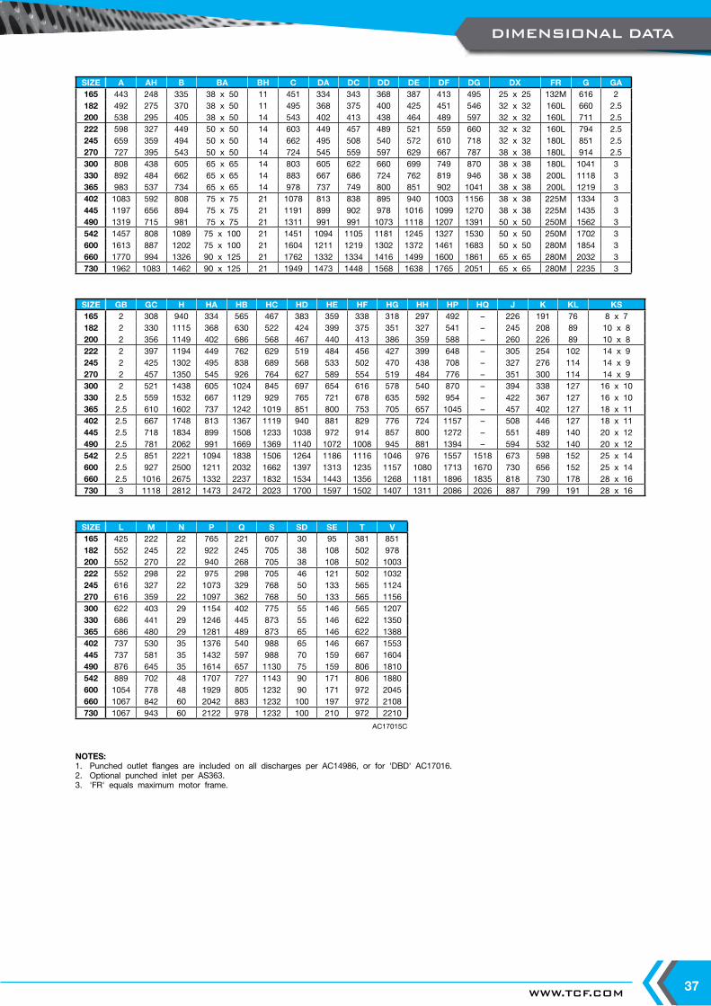
SIZE A AH B BA BH C DA DC DD DE DF DG DX FR G GA165 443 248 335 38 x 50 11 451 334 343 368 387 413 495 25 x 25 132M 616 2182 492 275 370 38 x 50 11 495 368 375 400 425 451 546 32 x 32 160L 660 2.5200 538 295 405 38 x 50 14 543 402 413 438 464 489 597 32 x 32 160L 711 2.5222 598 327 449 50 x 50 14 603 449 457 489 521 559 660 32 x 32 160L 794 2.5245 659 359 494 50 x 50 14 662 495 508 540 572 610 718 32 x 32 180L 851 2.5270 727 395 543 50 x 50 14 724 545 559 597 629 667 787 38 x 38 180L 914 2.5300 808 438 605 65 x 65 14 803 605 622 660 699 749 870 38 x 38 180L 1041 3330 892 484 662 65 x 65 14 883 667 686 724 762 819 946 38 x 38 200L 1118 3365 983 537 734 65 x 65 14 978 737 749 800 851 902 1041 38 x 38 200L 1219 3402 1083 592 808 75 x 75 21 1078 813 838 895 940 1003 1156 38 x 38 225M 1334 3445 1197 656 894 75 x 75 21 1191 899 902 978 1016 1099 1270 38 x 38 225M 1435 3490 1319 715 981 75 x 75 21 1311 991 991 1073 1118 1207 1391 50 x 50 250M 1562 3542 1457 808 1089 75 x 100 21 1451 1094 1105 1181 1245 1327 1530 50 x 50 250M 1702 3600 1613 887 1202 75 x 100 21 1604 1211 1219 1302 1372 1461 1683 50 x 50 280M 1854 3660 1770 994 1326 90 x 125 21 1762 1332 1334 1416 1499 1600 1861 65 x 65 280M 2032 3730 1962 1083 1462 90 x 125 21 1949 1473 1448 1568 1638 1765 2051 65 x 65 280M 2235 3
AC17015C
NOTES:1. Punched outlet flanges are included on all discharges per AC14986, or for 'DBD' AC17016.2. Optional punched inlet per AS363.3. 'FR' equals maximum motor frame.
SIZE GB GC H HA HB HC HD HE HF HG HH HP HQ J K KL KS165 2 308 940 334 565 467 383 359 338 318 297 492 – 226 191 76 8 x 7182 2 330 1115 368 630 522 424 399 375 351 327 541 – 245 208 89 10 x 8200 2 356 1149 402 686 568 467 440 413 386 359 588 – 260 226 89 10 x 8222 2 397 1194 449 762 629 519 484 456 427 399 648 – 305 254 102 14 x 9245 2 425 1302 495 838 689 568 533 502 470 438 708 – 327 276 114 14 x 9270 2 457 1350 545 926 764 627 589 554 519 484 776 – 351 300 114 14 x 9300 2 521 1438 605 1024 845 697 654 616 578 540 870 – 394 338 127 16 x 10330 2.5 559 1532 667 1129 929 765 721 678 635 592 954 – 422 367 127 16 x 10365 2.5 610 1602 737 1242 1019 851 800 753 705 657 1045 – 457 402 127 18 x 11402 2.5 667 1748 813 1367 1119 940 881 829 776 724 1157 – 508 446 127 18 x 11445 2.5 718 1834 899 1508 1233 1038 972 914 857 800 1272 – 551 489 140 20 x 12490 2.5 781 2062 991 1669 1369 1140 1072 1008 945 881 1394 – 594 532 140 20 x 12542 2.5 851 2221 1094 1838 1506 1264 1186 1116 1046 976 1557 1518 673 598 152 25 x 14600 2.5 927 2500 1211 2032 1662 1397 1313 1235 1157 1080 1713 1670 730 656 152 25 x 14660 2.5 1016 2675 1332 2237 1832 1534 1443 1356 1268 1181 1896 1835 818 730 178 28 x 16730 3 1118 2812 1473 2472 2023 1700 1597 1502 1407 1311 2086 2026 887 799 191 28 x 16
SIZE L M N P Q S SD SE T V165 425 222 22 765 221 607 30 95 381 851182 552 245 22 922 245 705 38 108 502 978200 552 270 22 940 268 705 38 108 502 1003222 552 298 22 975 298 705 46 121 502 1032245 616 327 22 1073 329 768 50 133 565 1124270 616 359 22 1097 362 768 50 133 565 1156300 622 403 29 1154 402 775 55 146 565 1207330 686 441 29 1246 445 873 55 146 622 1350365 686 480 29 1281 489 873 65 146 622 1388402 737 530 35 1376 540 988 65 146 667 1553445 737 581 35 1432 597 988 70 159 667 1604490 876 645 35 1614 657 1130 75 159 806 1810542 889 702 48 1707 727 1143 90 171 806 1880600 1054 778 48 1929 805 1232 90 171 972 2045660 1067 842 60 2042 883 1232 100 197 972 2108730 1067 943 60 2122 978 1232 100 210 972 2210
DIMENSIONAL DATA

TWIN CITY FAN - CATALOGUE M40038
HE HA
HQ
DC
GCG
HC
Q
GAGA. SIDES
DISCHCL
NOTE 3
P J
KL
C
KS
N
SE
SD GB
DXDISCH.
FLANGE
KWYSIZE
DIA. SHAFTGA. SCROLL
BABASE ANGLES
OUTS
IDE
HOUSING
OUTSIDEHOUSING
O.D.
INLE
T
B
H
A
NOTE 1
CW DBDCW TAU CW UBD
CW BAUCW BHD
HGHP
HE
DA DD
HHHD
G
HQHC HG
HA
G
HB HF
HH
DF
HA
HG
DG
GD
DE
G
HE
HB
J
DISCH
C L
NOTE 2
WITH OPTIONALFLANGED INLET
K
K
M
BH
L
M
DIA. BASEHOLES
FAN HSGCL
FOUNDATION PLAN(FOR DBD SEE NOTE 1)
MOTOR LOCATION ‘L’ (LEFT) SHOWN
FAN S
HAFT
C L
T
S
MOTO
RC L
G
CW THD
Arrangement 9F, Class 17
DIMENSIONAL DATA
WWW.TCF.COM 39
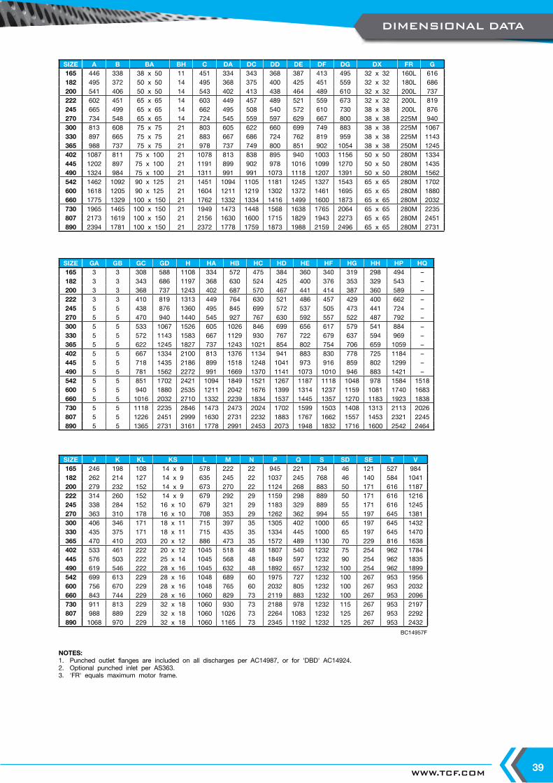
SIZE A B BA BH C DA DC DD DE DF DG DX FR G165 446 338 38 x 50 11 451 334 343 368 387 413 495 32 x 32 160L 616182 495 372 50 x 50 14 495 368 375 400 425 451 559 32 x 32 180L 686200 541 406 50 x 50 14 543 402 413 438 464 489 610 32 x 32 200L 737222 602 451 65 x 65 14 603 449 457 489 521 559 673 32 x 32 200L 819245 665 499 65 x 65 14 662 495 508 540 572 610 730 38 x 38 200L 876270 734 548 65 x 65 14 724 545 559 597 629 667 800 38 x 38 225M 940300 813 608 75 x 75 21 803 605 622 660 699 749 883 38 x 38 225M 1067330 897 665 75 x 75 21 883 667 686 724 762 819 959 38 x 38 225M 1143365 988 737 75 x 75 21 978 737 749 800 851 902 1054 38 x 38 250M 1245402 1087 811 75 x 100 21 1078 813 838 895 940 1003 1156 50 x 50 280M 1334445 1202 897 75 x 100 21 1191 899 902 978 1016 1099 1270 50 x 50 280M 1435490 1324 984 75 x 100 21 1311 991 991 1073 1118 1207 1391 50 x 50 280M 1562542 1462 1092 90 x 125 21 1451 1094 1105 1181 1245 1327 1543 65 x 65 280M 1702600 1618 1205 90 x 125 21 1604 1211 1219 1302 1372 1461 1695 65 x 65 280M 1880660 1775 1329 100 x 150 21 1762 1332 1334 1416 1499 1600 1873 65 x 65 280M 2032730 1965 1465 100 x 150 21 1949 1473 1448 1568 1638 1765 2064 65 x 65 280M 2235807 2173 1619 100 x 150 21 2156 1630 1600 1715 1829 1943 2273 65 x 65 280M 2451890 2394 1781 100 x 150 21 2372 1778 1759 1873 1988 2159 2496 65 x 65 280M 2731
BC14957F
NOTES:1. Punched outlet flanges are included on all discharges per AC14987, or for 'DBD' AC14924.2. Optional punched inlet per AS363.3. 'FR' equals maximum motor frame.
SIZE GA GB GC GD H HA HB HC HD HE HF HG HH HP HQ165 3 3 308 588 1108 334 572 475 384 360 340 319 298 494 –182 3 3 343 686 1197 368 630 524 425 400 376 353 329 543 –200 3 3 368 737 1243 402 687 570 467 441 414 387 360 589 –222 3 3 410 819 1313 449 764 630 521 486 457 429 400 662 –245 5 5 438 876 1360 495 845 699 572 537 505 473 441 724 –270 5 5 470 940 1440 545 927 767 630 592 557 522 487 792 –300 5 5 533 1067 1526 605 1026 846 699 656 617 579 541 884 –330 5 5 572 1143 1583 667 1129 930 767 722 679 637 594 969 –365 5 5 622 1245 1827 737 1243 1021 854 802 754 706 659 1059 –402 5 5 667 1334 2100 813 1376 1134 941 883 830 778 725 1184 –445 5 5 718 1435 2186 899 1518 1248 1041 973 916 859 802 1299 –490 5 5 781 1562 2272 991 1669 1370 1141 1073 1010 946 883 1421 –542 5 5 851 1702 2421 1094 1849 1521 1267 1187 1118 1048 978 1584 1518600 5 5 940 1880 2535 1211 2042 1676 1399 1314 1237 1159 1081 1740 1683660 5 5 1016 2032 2710 1332 2239 1834 1537 1445 1357 1270 1183 1923 1838730 5 5 1118 2235 2846 1473 2473 2024 1702 1599 1503 1408 1313 2113 2026807 5 5 1226 2451 2999 1630 2731 2232 1883 1767 1662 1557 1453 2321 2245890 5 5 1365 2731 3161 1778 2991 2453 2073 1948 1832 1716 1600 2542 2464
SIZE J K KL KS L M N P Q S SD SE T V165 246 198 108 14 x 9 578 222 22 945 221 734 46 121 527 984182 262 214 127 14 x 9 635 245 22 1037 245 768 46 140 584 1041200 279 232 152 14 x 9 673 270 22 1124 268 883 50 171 616 1187222 314 260 152 14 x 9 679 292 29 1159 298 889 50 171 616 1216245 338 284 152 16 x 10 679 321 29 1183 329 889 55 171 616 1245270 363 310 178 16 x 10 708 353 29 1262 362 994 55 197 645 1381300 406 346 171 18 x 11 715 397 35 1305 402 1000 65 197 645 1432330 435 375 171 18 x 11 715 435 35 1334 445 1000 65 197 645 1470365 470 410 203 20 x 12 886 473 35 1572 489 1130 70 229 816 1638402 533 461 222 20 x 12 1045 518 48 1807 540 1232 75 254 962 1784445 576 503 222 25 x 14 1045 568 48 1849 597 1232 90 254 962 1835490 619 546 222 28 x 16 1045 632 48 1892 657 1232 100 254 962 1899542 699 613 229 28 x 16 1048 689 60 1975 727 1232 100 267 953 1956600 756 670 229 28 x 16 1048 765 60 2032 805 1232 100 267 953 2032660 843 744 229 28 x 16 1060 829 73 2119 883 1232 100 267 953 2096730 911 813 229 32 x 18 1060 930 73 2188 978 1232 115 267 953 2197807 988 889 229 32 x 18 1060 1026 73 2264 1083 1232 125 267 953 2292890 1068 970 229 32 x 18 1060 1165 73 2345 1192 1232 125 267 953 2432
DIMENSIONAL DATA

TWIN CITY FAN - CATALOGUE M40040
HE HA
HQ
DC
GCG
HC
GAGA. SIDES
DISCHCL
NOTE 3
Q
P J
KL
C
KS
N
SE
SD GB
DXDISCH.
FLANGE
KWYSIZE
DIA. SHAFT GA. SCROLL
BABASE ANGLES
OUTS
IDE
HOUSING
OUTSIDEHOUSING
O.D.
INLE
T
B
H
A
NOTE 1
CW DBDCW TAU CW UBD CW BAU CW BHD
HGHP
HE
DA DD
HHHD
G
HQHC HG
HA
G
HB HF
HH
DF
HA
HG
DG
G
DE
G
HE
HB
G
J
DISCH
C L
NOTE 2
WITH OPTIONALFLANGED INLET
K
K
M
BH
L
M
DIA. BASEHOLES
FAN HSGCL
FOUNDATION PLAN(FOR DBD SEE NOTE 1)
MOTOR LOCATION ‘L’ (LEFT) SHOWN
FAN S
HAFT
C LT
S
MOTO
RC L
CW THD
Arrangement 9F, Class 22
DIMENSIONAL DATA

WWW.TCF.COM 41
SIZE A B BA BH C DA DC DD DE DF DG DX FR G222 605 454 75 x 75 14 603 449 457 489 521 559 673 50 x 50 225M 819245 665 499 75 x 75 14 662 495 508 540 572 610 730 50 x 50 225M 876270 734 548 75 x 75 14 724 545 559 597 629 667 800 50 x 50 225M 965300 813 608 75 x 100 21 803 605 622 660 699 749 883 50 x 50 225M 1067330 900 668 75 x 100 21 883 667 686 724 762 819 959 50 x 50 250M 1143365 991 740 75 x 100 21 978 737 749 800 851 902 1054 50 x 50 280M 1245402 1091 814 90 x 125 21 1078 813 838 895 940 1003 1168 50 x 50 280M 1334445 1205 900 100 x150 21 1191 899 902 978 1016 1099 1283 50 x 50 280M 1461490 1327 988 100 x150 21 1311 991 991 1073 1118 1207 1403 50 x 50 280M 1588542 1465 1096 100 x150 21 1451 1094 1105 1181 1245 1327 1556 65 x 65 280M 1727
BC14958D
NOTES:1. Punched outlet flanges are included on all discharges per AC14988, or for 'DBD' AC14925.2. Optional punched inlet per AS363.3. 'FR' equals maximum motor frame.
SIZE GA GB GC H HA HB HC HD HE HF HG HH HP HQ222 5 5 410 1370 449 778 651 522 487 459 430 402 676 –245 5 5 438 1408 495 852 711 572 537 505 473 441 737 –270 5 5 483 1459 545 937 780 630 592 557 522 487 805 –300 5 5 533 1570 605 1035 859 699 656 617 579 541 910 –330 6 6 572 1802 667 1140 945 768 724 681 638 595 995 –365 6 6 622 2027 737 1252 1035 856 803 756 708 660 1086 –402 6 6 667 2154 813 1378 1135 943 884 832 780 727 1211 –445 6 6 730 2281 899 1519 1249 1043 975 918 861 803 1351 –490 6 6 794 2367 991 1670 1372 1143 1075 1011 948 884 1473 –542 6 6 864 2475 1094 1849 1522 1268 1189 1119 1049 979 1611 1534
SIZE J K KL KS L M N P Q S SD SE T V222 329 268 178 18 x 11 715 286 35 1227 298 1000 65 197 645 1321245 351 291 178 18 x 11 708 314 35 1249 329 1000 65 203 638 1350270 376 316 178 18 x 11 708 346 35 1275 362 1000 65 203 638 1381300 432 359 178 20 x 12 721 384 48 1330 402 1013 70 203 638 1432330 462 389 210 20 x 12 889 422 48 1567 445 1143 75 241 806 1600365 497 424 222 20 x 12 1045 473 48 1770 489 1232 75 254 962 1740402 560 475 222 25 x 14 1057 505 60 1834 540 1232 90 254 962 1772445 629 530 229 28 x 16 1060 543 73 1905 597 1232 100 267 953 1810490 672 573 229 28 x 16 1060 607 73 1948 657 1232 100 267 953 1873542 725 627 229 32 x 18 1060 676 73 2002 727 1232 115 267 953 1943
DIMENSIONAL DATA

TWIN CITY FAN - CATALOGUE M40042
Fans shall be Model BCS, Backward Curved High Pressure Blowers, as manufactured by Twin City Fan & Blower.
PERFORMANCE — Fans shall be tested in accordance with ANSI/AMCA Standard 210 (air performance) and 300 (sound performance) in an AMCA accredited laboratory.
Fans shall have a sharply rising pressure characteristic extending through the operating range and continuing to rise beyond the peak efficiency to ensure quiet and stable operation. Fans shall have a non-overloading design with self-limiting horsepower characteristics and shall reach a peak in the normal selection area.
CONSTRUCTION — Fan housings and bearing pedestals shall be of heavy-gauge, continuously welded construction. Housings with partially welded construction are not acceptable. Housings shall be suitably braced to prevent vibration or pulsation. Discharge flanges shall be provided for rigidity and duct connection. Discharge flanges are punched as standard. All units are furnished with lifting lugs.
IMPELLER — BCS backward curved impellers shall be single thickness, designed for maximum efficiency and quiet operation, and shall be continuously welded to the rim and back plate. Partial welding is not acceptable on backward curved blades. All impellers shall be statically and dynamically balanced.
SHAFT — Shafts shall be AISI 1018, 1040 or 1045 hot rolled steel, accurately turned, ground, polished, and ring gauged for accuracy. Shafts shall be sized for the first critical speed of at least 1.43 times the maximum speed.
BEARINGS — Bearings shall be heavy duty, grease lubricated, anti-friction ball or roller, self-aligning, pillow block type and selected for a minimum average bearing life (AFBMA L-50) in excess of 200,000 hours at the maximum fan RPM.
DRIVE — Motor sheaves shall be cast iron, variable pitch on applications 20 HP and smaller, and fixed pitch on 25 HP and larger. Drives and belts shall be located external to the fan casing and rated for 150% of the required motor HP.
FINISH AND COATING — The entire fan assembly, excluding the shaft, shall be thoroughly degreased and deburred before application of a rust-preventative primer. After the fan is completely assembled, a finish coat of paint shall be applied to the entire assembly. The fan shaft shall be coated with a petroleum-based rust protectant. Aluminum components shall be unpainted.
ACCESSORIES — When specified, accessories such as access doors, drains, inlet and outlet flanges, belt guards, shaft and bearing guards, outlet screens, outlet dampers, inlet vanes, spark resistant construction, split housings, high temperature construction, shaft seals, inlet boxes, and shaft coolers shall be provided by Twin City Fan & Blower to maintain one-source responsibility.
FACTORY RUN TEST — All fans prior to shipment shall be completely assembled and test run as a unit at the specified operating speed or maximum RPM allowed for the particular construction type. Each impeller shall be stati-cally and dynamically balanced in accordance with ANSI/AMCA 204-96 “Balance Quality and Vibration Levels for Fans” to Fan Application Category BV-3, Balance Quality Grade G6.3. Balance readings shall be taken by electronic type equipment in the axial, vertical, and horizontal directions on each of the bearings. Records shall be maintained and a written copy shall be available upon request.
GUARANTEE — The manufacturer shall guarantee the workmanship and materials for at least one (1) year from startup or eighteen (18) months from shipment, whichever occurs first.
ModelBCS
TYPICAL SPECIFICATIONS
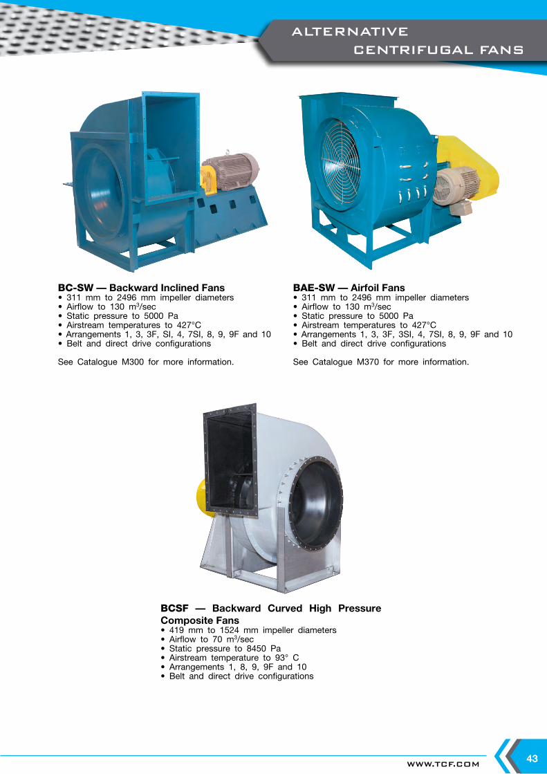
WWW.TCF.COM 43
BCSF — Backward Curved High Pressure Composite Fans• 419 mm to 1524 mm impeller diameters• Airflow to 70 m3/sec• Static pressure to 8450 Pa• Airstream temperature to 93° C• Arrangements 1, 8, 9, 9F and 10• Belt and direct drive configurations
BC-SW — Backward Inclined Fans• 311 mm to 2496 mm impeller diameters• Airflow to 130 m3/sec• Static pressure to 5000 Pa• Airstream temperatures to 427°C• Arrangements 1, 3, 3F, SI, 4, 7SI, 8, 9, 9F and 10• Belt and direct drive configurations
See Catalogue M300 for more information.
BAE-SW — Airfoil Fans• 311 mm to 2496 mm impeller diameters• Airflow to 130 m3/sec• Static pressure to 5000 Pa• Airstream temperatures to 427°C• Arrangements 1, 3, 3F, 3SI, 4, 7SI, 8, 9, 9F and 10• Belt and direct drive configurations
See Catalogue M370 for more information.
ALTERNATIVE CENTRIFUGAL FANS

TWIN CITY FAN & BLOWERWWW.TCF.COM
5959 TRENTON LANE N | MINNEAPOLIS, MN 55442 | PHONE: 763-551-7600 | FAX: 763-551-7601
CENTRIFUGAL FANS | UTILITY SETS | PLENUM & PLUG FANS | INLINE CENTRIFUGAL FANS
MIXED FLOW FANS | TUBEAXIAL & VANEAXIAL FANS | PROPELLER WALL FANS | PROPELLER ROOF VENTILATORS
CENTRIFUGAL ROOF & WALL EXHAUSTERS | CEILING VENTILATORS | GRAVITY VENTILATORS | DUCT BLOWERS
RADIAL BLADED FANS | RADIAL TIP FANS | HIGH EFFICIENCY INDUSTRIAL FANS | PRESSURE BLOWERS
LABORATORY EXHAUST FANS | FILTERED SUPPLY FANS | MANCOOLERS | FIBERGLASS FANS | CUSTOM FANS
INDUSTRIAL PROCESS ANDCOMMERCIAL VENTILATION SYSTEMS
©2018 Twin City Fan Companies, Ltd., Minneapolis, MN. All rights reserved. Catalog illustrations cover the general appearance of Twin City
Fan & Blower products at the time of publication and we reserve the right to make changes in design and construction at any time without notice.
Twin City Fan
Twin City Fan


