doi:10.1016/j.jmb.2006.08.049 J. Mol. Biol. (2006) 363, 577–588
Bacteriophage T4 Capsid: A Unique Platform forEfficient Surface Assembly of MacromolecularComplexes
Qin Li1, Sathish B. Shivachandra1, Stephen H. Leppla2
and Venigalla B. Rao1⁎
1Department of Biology, TheCatholic University of America,620 Michigan Ave, NE,Washington, DC, 20064, USA2Laboratory of BacterialDiseases, National Institute ofAllergy and Infectious Diseases,NIH, 30 Convent Dr., Bethesda,MD 20892, USA
Abbreviations used: aa, amino acidgp, gene product(s); LF, lethal factordomain of lethal factor; LTx, lethal tantigen; SOE, splicing by overlap exE-mail address of the correspondi
We report the first description of a macromolecular complex display systemusing bacteriophage T4. Decorated with two dispensable outer capsidproteins, Hoc (155 copies) and Soc (810 copies), the 120 nm×86 nm T4capsid particle offers a unique binding site-rich platform for surfaceassembly of hetero-oligomeric complexes. To display the 710 kDa anthraxtoxin complex, two bipartite functional fusion proteins, LF-Hoc and LFn-Soc, were constructed. Using a defined in vitro binding system, sequentialassembly was performed by first attaching LF-Hoc and/or LFn-Soc tohoc–soc– phage, saturating the Hoc and Soc binding sites. Trypsin-nickedPA63 was then assembled into heptamers through specific interaction withthe capsid-exposed LFn domain. EF was then attached to the unoccupiedsites of PA63 heptamers, completing the assembly of the tripartite anthraxtoxin. Negative electron microscopy showed decoration of each capsid witha layer of heptameric PA63 rings. Up to 229 anthrax toxin complexes,equivalent to a total of 2400 protein molecules and a mass of about 133 MDa(2.7 times the mass of capsid shell), were anchored on a single particle,making it the highest density display reported on any virus. The phage T4capsid lattice provides a stable biological platform allowing maximumdisplay of large hetero-oligomeric complexes in vitro and offers insights fordeveloping novel vaccines, analysis of protein–protein interactions, andstructure determination of complexes.
Since the first description of peptide display onphage fd,1 numerous display systems usingphages,2–6 animal and plant viruses,7,8 and bacterialsurfaces,9,10 have emerged for a variety of biologicalapplications. All these systems are in vivo-based,generally limited to displaying a single component,a peptide, domain, or protein, fused to an essential,or conditionally essential, outer structural protein.Display of multiple components, or macromolecular
complexes, is very limited, or not feasible, using theclassic in vivo phage display approaches.One of the limitations of in vivo display is that no
control can be exerted on intracellular expression,structure, and assembly of foreign protein(s). In thefew examples where attempts were made to displaycomplexes, for instance tetramers of Escherichia coliβ-galactosidase (116 kDa) on phages λ4,11 or T7,12
the copy numbers obtained were quite low; only ≤one copy of β-galactosidase tetramer per phageparticle was displayed using gpV (major tail proteinof phage λ; 192 copies per particle) or gp10 (majorcapsid protein of phage T7; 415 copies per particle).Higher copy numbers, up to 34 per particle, wereachieved when it was displayed through the phageλ outer capsid protein, gpD (420 copies perparticle),4 but no additional studies have beenreported to adapt this system for general displayof hetero-oligomeric complexes.
Efficient assembly of macromolecular complexeson phage particle will enable novel applications.Where neutralization epitopes are conformationallyconstrained in a complex (e.g. trimeric HIV gp120/gp41 envelope glycoprotein),13–15 a system able todisplay complexes would allow presentation ofepitopes in native conformations. Particles display-ing complexes can be used as baits to identify novelinteractions to hitherto unknown ligands. Cryo-EMand image reconstruction of displayed phage cangenerate structures of bound complexes that arerefractory to crystallization.16
Bacteriophage T4 capsid provides a uniquebinding site-rich platform for display of macromo-lecular complexes. It is a prolate icosahedron(length, 120 nm; width 86 nm) composed of themajor capsid protein, gp23*† (49 kDa, 930 copies),which forms the hexagonal lattice of the capsidshell; the vertex protein, gp24* (47 kDa, 55 copies),which occupies 11 of the 12 5-fold vertices; and theportal protein, gp20 (61 kDa, 12 copies), a dodeca-mer that forms the unique head-tail connectorvertex through which DNA enters and exits thephage head (see Figure 6).17 Early biochemicalstudies by Ishii and Yanagida,18 and recent cryo-electron microscopy reconstructions,17,19,20 revealedthe presence of two dispensable proteins, Hoc(highly antigenic outer capsid protein, 39 kDa)and Soc (small outer capsid protein, 10 kDa), on theouter surface of the particle. These decorate thecapsid at high density with a combined total of 965copies per particle. Hoc, a monomer, is present up to155 copies per capsid in the center of the gp23*hexon, whereas 810 copies of Soc, visualized astrimers on capsid shell, bridge the adjacenthexons.17–20 Foreign peptides or full-length proteinshave been fused to the N and C termini of eitherprotein and displayed on the capsid surface.5,21–23
Recently, we have developed an in vitro approachthat distinguishes itself from the classic in vivodisplay in that it allows efficient and controlleddisplay of large full-length proteins on the capsidsurface through specific interactions between Hocand capsid.24 A variety of proteins, anthrax toxins,phage packaging proteins, and HIV antigens ofvarious size (up to 90 kDa), structure, and biologicalfunction, have been fused to Hoc, over-expressed inE. coli, purified and assembled on the phageparticles in a native functional state, under definedbinding conditions.24,25
Here we report a novel approach to assemble‡macromolecular complexes on bacteriophage T4.The native anthrax toxin complex consisting ofthree components, protective antigen (PA, 83 kDa),lethal factor (LF, 90 kDa), and edema factor (EF,
† *Represents the cleaved mature capsid protein follow-ing T4 capsid assembly-dependent maturation cleavages.‡Assembly refers to the binding of Hoc/Soc fusion
proteins to the symmetrically arranged binding sites onthe T4 capsid surface. The terms assembly, binding,display and attachment are interchangeably used to referthis process.
89 kDa), having a size of about 710 kDa, was usedas a model to develop the system. In the anthraxtoxin pathway, PA interacts with the host cellreceptor, ATR or CMG2 receptor, through the C-terminal domain-4 of PA26 following which it iscleaved at amino acid (aa) 167 by the membrane-bound protease, furin. The activated form, PA63(63 kDa), forms a ring-shaped heptamer,27 whichinteracts with the N-terminal domain of LF (LFn)and/or EF (EFn) to form the biologically activeanthrax lethal toxin (LTx) and edema toxin (ETx).LF and EF are then translocated into the cytosolthrough the heptamer channel where they exerttoxic effects.28
Our strategy involves the attachment of LF§ orLFn to phage T4 through Hoc/Soc-capsid interac-tions so that the LFn domain is exposed on theouter surface. Soluble PA was nicked to PA63 bytrypsin to expose the LFn-interacting PA domain-1′.The PA63 heptamerizes and assembles on phage T4through interaction with the T4-exposed LFndomain. Assembly was further extended to EF byits binding to the unoccupied sites of PA63heptamer, thus generating the complete anthraxtoxin consisting of “three layers” of bound proteinson T4 surface.The data showed that a massive number of pure,
functionally intact protein molecules, about 2400molecules of anthrax toxin components with a totalmass of 133 MDa can be assembled into complexeson the T4 capsid through Hoc and Soc attachmentsites. To our knowledge, this system represents thefirst report of a stable, efficient, phage platform forhigh density display of large hetero-oligomericcomplexes. The data provide insights on thestoichiometry of bound complexes as well aspotentially novel applications in vaccine develop-ment, structure determination, and analysis ofprotein–protein interactions.
Results
Bipartite functional LF-Hoc and LFn-Soc fusions
The biochemical pathway for LTx formationinvolves interaction of the N-terminal LFn domain(aa 1–263) with the PA domain-1′ of two adjacentsubunits of the PA63 heptamer.31 Based on thesolved structures of PA and LF,32,33 we hypothe-sized that fusion of LF or LFn to the N terminus ofHoc or Soc would create a bipartite functionalprotein with the N-terminal LFn domain exposedfor interaction with PA63 heptamer, whereas the C-terminal Hoc/Soc domain would be available for
§ In this study, null mutants of LF and EF, LFE687C andEFK346R, which exhibit no detectable MAPKK proteaseand adenyl cyclase activities, respectively, were used toeliminate the toxicity of anthrax toxin complexes.29,30 Themutants however retained their binding functions andimmunogenicity.
Figure 1. Construction, expression, and purification of LF-Hoc and LFn-Soc. (a) Schematic of recombinant fusions. APCR-based SOE strategy38,39 was used to construct LF-Hoc and LFn-Soc gene fusions. LF and LFn genes (white) werefused to hoc (purple) and soc (orange), respectively, via the linker (blue) as shown. Hexa-histidine tag (yellow) wasattached to the N terminus of each gene fusion. The basic features of each segment of the recombinants are shown in therectangular boxes; numbers in parentheses represent the number of aa; the E687C null mutation in LF is shown in red. SeeMaterials and Methods for additional details. (b) and (c) Over-expression in E. coli and purification of LF-Hoc and LFn-Soc. Lanes: 1,Mr standards; 2 and 3, samples before and after (2.5 h) IPTG induction, respectively; 4, purified protein afterHisTrap column chromatography. The positions of LF-Hoc (b) and LFn-Soc (c) are indicated by arrows.
579Macromolecular Complex Assembly on Phage T4
interaction with the capsid (Figure 1(a))∥. Consider-ing that Hoc projects ∼60 Å away from the capsidsurface, we argued that the large 90 kDa LF wouldbe more readily accommodated in the 3D space if itis fused to Hoc rather than to Soc. On the other hand,the smaller 30 kDa LFn domain would be moresuitable for fusion with Soc, as Soc is tightlyassociated with the capsid wall.17 Both LF-Hocand LFn-Soc fusions were constructed by the SOEstrategy with a four aa structureless linker, SASA,between the domains and a hexa-histidine tag at theN terminus (Figure 1(a); see Materials and Meth-ods). The fusion proteins were over-expressed in E.coli and purified by HisTrap column chromatogra-phy and FPLC gel filtration (Figure 1(b) and (c)).
LF-Hoc and LFn-Soc form LTx¶ complexes withnicked anthrax PA
The ability of LF-Hoc and LFn-Soc to interact withtrypsin-cleaved nPAa (nicked PA or PA63; 63 kDa)was assessed by an in vitro binding assay. Native
∥The structural disposition of Hoc and Soc on phage T4capsid surface is unknown. Recent biochemical and cryo-EM evidence (Sathaliyawala et al.,25 and unpublisheddata) indicates that the capsid binding site resides in the Cterminus of Hoc, and in the case of Soc, in the centralregion of the Soc polypeptide. Thus, the N-terminal LFand LFn fusions to Hoc and Soc, respectively, asconstructed in this study, do not affect their capsidbinding properties (see Figure 3).¶ LTx refers to lethal toxin-like complexes formed
through interaction between nicked PA and, dependingon the context, native LF, LFE687C, LFn domain, LFE687C-Hoc, or LFn-Soc.
a nPA or PA63 are interchangeably used to refer totrypsin-nicked PA.
PAGE results showed that both the constructsformed complexes as efficiently as the native LF(Figure 2(a), lanes 6–8); the same was observedwhen purified PA63 heptamer was used instead ofnPA (data not shown). The migration patterns of thecomplexes were very similar to those reported fornative LTx complexes,34 suggesting that the struc-ture and folding of LFn domain is not compromisedby fusion to Hoc or Soc. This was further supportedby quantitative ELISA capture assays, whichshowed that both LF-Hoc and LFn-Soc bound toLF monoclonal antibody (LF5C8) as well as thenative LF (data not shown).
LF-Hoc and LFn-Soc bind to hoc–soc– phage
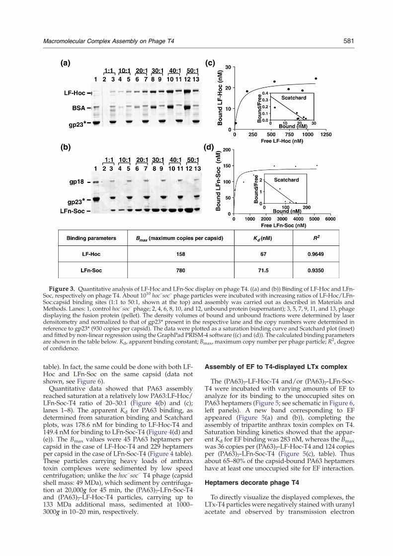
Both LF-Hoc and LFn-Soc could be efficientlyattached to hoc–soc– T4 phage in vitro eitherindividually, or together on the same capsid(Figure 2(b), compare lanes 2, 3 and 4 to lane 1).When mixed with a control protein, BSA, only theLF-Hoc was selectively transferred to phage,demonstrating the specificity of interactionbetween the fusion protein and the capsid (Figure3(a); specificity for LFn-Soc versus BSA was alsoobserved; data not shown). Quantitative datashowed that binding reached saturation at a ratioof LF-Hoc or LFn-Soc molecules to Hoc or Socbinding sites of about 30:1 (Figure 3(a) and (b);lanes 2–9); no further increase was evident up to aratio of 50:1 (lanes 10–13).The apparent Kd for LF-Hoc and LFn-Soc binding
are 67 nM and 71.5 nM, respectively (Figure 3(c) and(d)), which are very close to that of native Hoc(85 nM) or Soc binding (54 nM) (26; Q. L. et al.,unpublished data). The Bmax, defined as the max-imum copy number of bound fusion protein per
Figure 2. LF-Hoc and LFn-Soc retained the bipartitefunctions. See Materials andMethods for details on in vitrobinding and in vitro display procedures. (a) In vitrobinding of LF-Hoc and LFn-Soc to nPA as analyzed bynative PAGE (4–12% gradient) followed by staining withCoomassie blue. Lanes: 1, PA; 2, LFn-Soc; 3, LF; 4, LF-Hoc;5, nPA showing the cleaved PA63 and PA20 fragments;note that a portion of PA63 formed heptamers andmigrated to the high molecular mass position; 6, nPA +LFn-Soc (LTx-Soc); 7, nPA + LF (LTx); 8, nPA + LF-Hoc(LTx-Hoc). (b) In vitro display of LF-Hoc and/or LFn-Socon hoc–soc– phage. Lanes: M, Mr standards; 1, controlhoc–soc– phage; note the presence of two major bands inthe control phage, gp23*, the major capsid protein, andgp18, the major tail protein (71 kDa); 2, phage displaying
580 Macromolecular Complex Assembly on Phage T4
capsid particleb, was 158 for LF-Hoc and 780 forLFn-Soc (Figure 3, table). These data indicate thatthe high affinity interactions as well as the mode andcopy number of Hoc and Soc binding to capsidremained unaltered in the fusion constructs.
Soluble LTx-Hoc complexes can be attached toT4 capsid
Several lines of evidence show that an LTxcomplex on the surface of a target cell such as themacrophage consists of heptameric PA63 with up tothree molecules of bound LF and/or EF.31,35 Todetermine whether this large LTx complex (710 kDa)can be assembled on the phage capsid surface, LTxcomplexes were first formed in solution by incubat-ing LF-Hoc with excess nPA so that all the LF-Hocwill be complexed with PA63. These LTx complexeswith “Hoc tails” were then incubated with hoc–soc–
phage. Two new bands corresponding to LF-Hocand PA63 appeared with T4 phage (Figure 4(a), lane4). In a control experiment, neither the native LTxthat lacks Hoc fusion ((PA63)7-LF, lane 2) nor thePA20 released following trypsin cleavage (data notshown) could bind to phage, demonstrating thespecificity of LTx binding to phage through fusedHoc.
Sequential assembly of LTx complexes onphage T4 capsid
To determine whether the LTx complexes could besequentially assembled on T4 phage, the hoc–soc–
phage was first saturated with LF-Hoc yielding 145copies of LF-Hoc per particle (hereafter referred to asLF-Hoc-T4c; Figure 4(b), lane 2) and then incubatedwith nPA. The nPA is expected to oligomerize intoheptamers; however, heptamerization is more effi-cient in the presence of LFn36 (data not shown).Therefore, in the presence of LF-Hoc-T4, PA63heptamerization should occur efficiently and theheptamers thus formed would be immobilized onthe T4 capsid through interaction with the exposedLFn domain (see schematic in Figure 6 below; leftpanels). This was indeed the case since a new bandcorresponding to PA63 appeared, the intensity ofwhich increased with increasing ratios of nPA:LF-Hoc binding sites (Figure 4(b)). A small amount of
LF-Hoc; 3, phage displaying LFn-Soc; 4, phage displayingboth LF-Hoc and LFn-Soc.bBmax refers to the maximum number of fusion protein
molecules bound per phage particle under the experi-mental conditions used. This was determined from thesaturation binding curve generated using increasingratios of fusion protein molecules to capsid binding sites(eg. Figure 3). Thus, Bmax is the maximum copy numberachieved experimentally, not the theoretical numberderived from the structural data.17 In most experimentshowever, the Bmax approached the theoretical maximum,demonstrating the high efficiency of the in vitro assemblyapproach.
cLF-Hoc-T4 refers to hoc–soc– phage T4 with displayedLF-Hoc. The same abbreviation style is followed through-out the manuscript. Additional examples: LFn-Soc-T4,LF-Hoc:LFn-Soc-T4, and (PA63)7-LF-Hoc-T4.
native (non-nicked) PA present in the reactionmixture, which served as an internal control, didnot bind, once again attesting to the specificity ofPA63 assembly (that the bound PA63 indeedassembled into heptamers was shown by electronmicroscopy; see below).A parallel sequential assembly experiment was
performed using LFn-Soc-T4 having 5.2 times asmany binding sites as that of LF-Hoc-T4. The datashowed that about five times more PA63 heptamerswere assembled on LFn-Soc-T4 (Figure 4(c), and
Figure 3. Quantitative analysis of LF-Hoc and LFn-Soc display on phage T4. ((a) and (b)) Binding of LF-Hoc and LFn-Soc, respectively on phage T4. About 1010 hoc–soc– phage particles were incubated with increasing ratios of LF-Hoc/LFn-Soc:capsid binding sites (1:1 to 50:1, shown at the top) and assembly was carried out as described in Materials andMethods. Lanes: 1, control hoc–soc– phage; 2, 4, 6, 8, 10, and 12, unbound protein (supernatant); 3, 5, 7, 9, 11, and 13, phagedisplaying the fusion protein (pellet). The density volumes of bound and unbound fractions were determined by laserdensitometry and normalized to that of gp23* present in the respective lane and the copy numbers were determined inreference to gp23* (930 copies per capsid). The data were plotted as a saturation binding curve and Scatchard plot (inset)and fitted by non-linear regression using the GraphPad PRISM-4 software ((c) and (d)). The calculated binding parametersare shown in the table below. Kd, apparent binding constant; Bmax, maximum copy number per phage particle; R2, degreeof confidence.
581Macromolecular Complex Assembly on Phage T4
table). In fact, the same could be done with both LF-Hoc and LFn-Soc on the same capsid (data notshown, see Figure 6).Quantitative data showed that PA63 assembly
reached saturation at a relatively low PA63:LF-Hoc/LFn-Soc-T4 ratio of 20–30:1 (Figure 4(b) and (c);lanes 1–8). The apparent Kd for PA63 binding, asdetermined from saturation binding and Scatchardplots, was 178.6 nM for binding to LF-Hoc-T4 and149.4 nM for binding to LFn-Soc-T4 (Figure 4(d) and(e)). The Bmax values were 45 PA63 heptamers percapsid in the case of LF-Hoc-T4 and 229 heptamersper capsid in the case of LFn-Soc-T4 (Figure 4 table).These particles carrying heavy loads of anthraxtoxin complexes were sedimented by low speedcentrifugation; unlike the hoc–soc– T4 phage (capsidshell mass: 49 MDa), which sediment by centrifuga-tion at 20,000g for 45 min, the (PA63)7-LFn-Soc-T4and (PA63)7-LF-Hoc-T4 particles, carrying up to133 MDa additional mass, sedimented at 1000–3000g in 10–20 min, respectively.
Assembly of EF to T4-displayed LTx complex
The (PA63)7-LF-Hoc-T4 and/or (PA63)7-LFn-Soc-T4 were incubated with varying amounts of EF toanalyze for its binding to the unoccupied sites onPA63 heptamers (Figure 5; see schematic in Figure 6,left panels). A new band corresponding to EFappeared (Figure 5(a) and (b)), completing theassembly of tripartite anthrax toxin complex on T4.Saturation binding kinetics showed that the appar-ent Kd for EF binding was 283 nM, whereas the Bmaxwas 36 copies per (PA63)7-LF-Hoc-T4 and 124 copiesper (PA63)7-LFn-Soc-T4 (Figure 5(c), table). Thusabout 65–80% of the capsid-bound PA63 heptamershave at least one unoccupied site for EF interaction.
Heptamers decorate phage T4
To directly visualize the displayed complexes, theLTx-T4 particles were negatively stained with uranylacetate and observed by transmission electron
Figure 4. Assembly of PA63 heptamers on phage T4. About 1010 hoc–soc– phage particles were incubated with variouscomponents of the anthrax toxin and assembly was carried out as described in Materials and Methods. (a) Assembly ofsoluble LTx-Hoc complexes onto T4. Lanes: 1, LTx (LF + nPA); 2, phage following incubation with LTx; 3, LTx-Hoc (LF-Hoc + nPA); 4, phage following incubation with LTx-Hoc. ((b) and (c)) Sequential assembly of LTx complexes on phage T4through displayed LF-Hoc (b) and LFn-Soc (c). LF-Hoc or LFn-Soc was first displayed on phage and nPAwas assembledusing increasing ratios of nPA:displayed LF-Hoc/LFn-Soc (1:1 to 50:1). Lanes: 1, 3, 5, 7, 9, and 11: unbound fraction; 2, 4, 6,8, 10, and 12, phage pellets with bound PA63. Quantitative analyses ((d) and (e)) were carried out as described in thelegend to Figure 3. Table, summary of binding parameters.
582 Macromolecular Complex Assembly on Phage T4
microscopy. Virtually 100% of the particles visua-lized in numerous random fields showed relativeuniform decoration of the capsid, but not the tail,with heptamer rings (Figure 6; note that the coverageby heptamer rings even extended to the region nearthe capsid-tail junction, (b)). The size and shape ofthe displayed oligomers were identical to that of thepurified PA63 heptamers added to the sample.Consistent with the quantified data (Figures 4 and5), fewer heptamerswere seen on (PA63)7-LF-Hoc-T4particles than on (PA63)7-LFn-Soc-T4. A gapbetween adjacent heptamers as well as a raiseabove the capsid wall were also visible on (PA63)7-LF-Hoc-T4 (Figure 6(a)), which are in keeping withthe disposition and copy number of LF-Hoc on thecapsid lattice. On the other hand, (PA63)7-LFn-Soc-T4 particles showed a continuous coat of heptamers,which are virtually “glued” to the capsid (Figure6(b)), as would be expected from the close proximityof LFn domain to the capsid wall (see schematic inFigure 6(a) showing the heptamer complex dis-played through full-length LF-Hoc more extended
away from the capsid than in (b) where the heptamerwas displayed through shorter LFn-Soc). The(PA63)7-LF-Hoc:(PA63)7-LFn-Soc-T4 particles, inwhich PA63 heptamers were assembled on phagedisplaying both LF-Hoc and LFn-Soc, showed theexpected combined pattern, i.e. gapped rings that areraised above the capsid plus a coat of rings tightlyassociated with the capsid wall (Figure 6(c)).
Discussion
We report the first macromolecular phage displaysystem that allows efficient assembly of large710 kDa tripartite anthrax toxin complexes onbacteriophage T4. In a defined in vitro reaction,pure and functionally well-characterized toxincomponents, PA, LF, and EF, were assembled onthe binding site-rich T4 capsid platform in acontrolled and sequential fashion. The results definethe features of the T4 assembly system and haveimplications for vaccine development, structure
Figure 5. Binding of EF to T4-displayed PA63 heptamers. (a) Purified EF was incubated with increasing ratio of EF:PA63 displayed on LF-Hoc-T4 (PA63)7-LF-Hoc-T4) (1:1 to 50:1 as shown at the top). Phage was sedimented bycentrifugation at 1000g for 30 min (4 °C) and the rest of the procedure was carried out as described in Materials andMethods. Lanes: M, Mr standards; 1, 3, 5, 7, 9, and 11, unbound EF; 2, 4, 6, 8, 10, and 12, phage bound EF. (b) EF wasincubated with (PA63)7-LF-Hoc-T4 (lane 4) or (PA63)7-LFn-Soc-T4 (lane 7) (30:1 ratio) and the rest of the procedure wasthe same as in (a). Lanes: M,Mr standards; 1, hoc
–soc– phage; 2, LF-Hoc-T4; lane 3, (PA63)7-LF-Hoc-T4; lane 5, LFn-Soc-T4;lane 6, (PA63)7-LFn-Soc-T4. The samples were electrophoresed on a 10% SDS-PAG and stained with Coomassie blue. (c)Quantitative analyses of EF binding to (PA63)7-LF-Hoc-T4 were carried out as described in the legend to Figure 3. Thecopy numbers are shown in the Table.
583Macromolecular Complex Assembly on Phage T4
determination, and analysis of protein–proteininteractions.Since Hoc spikes are 140 Å apart and the Soc
subunits are ∼60 Å from the nearest Hoc,17 weargued that this capsid architecture would allowindependent filling of both sets of binding sites,which could then be extended to assemble theinteracting partners. Indeed, the data demonstratethat LF-Hoc (132 kDa) and LFn-Soc (40 kDa) can bedisplayed either individually or together by simplyadding the purified proteins to the binding reaction.Display reached saturation at a relatively low ligandconcentration (0.5 μM for LF-Hoc; 2.4 μM for LFn-Soc), while the apparent Kd remained the same asthat for native Hoc or Soc binding. In a singlebinding reaction, virtually all the 965 binding siteswere filled and a “layer” of protein mass equivalentto >48 MDa was anchored on each capsid.Sequential assembly extended the display to
second and third layers through specific interactionwith the capsid-exposed LFn domain. Both LF-Hoc-T4 and LFn-Soc-T4 efficiently allowed oligomeriza-tion and assembly of PA63 heptameric rings on thecapsid. Electron microscopy revealed uniform dis-tribution of heptamers on the capsid exterior, butnot the tail. No major differences were observed inthe relative copy number (ratio of assembledheptamers to binding sites) of Hoc and Soc-mediated heptamer assembly, even though Hoc israised 60 Å above the capsid surface. This isprobably because the N terminus of Hoc, the point
of linkage to LF, is not located at the outside tip ofHoc spike but rather present at the other end, closerto the capsid wall as in the case of Soc fusion. This isconsistent with the recent mutagenesis and struc-tural modeling data, which place both the N and Ctermini of Hoc near the capsid, even though thebinding site is localized only in the C terminus (26; T.Sathaliyawala and V.B.R., unpublished results).Certain features distinguish the capsid-mediated
anthrax toxin assembly from that in solution. First,there was a drop in LF-Hoc/LFn-Soc affinity to nPAsince the Kd for LTx-Hoc/Soc–T4 assembly (178 nM)was ninefold higher than that in solution (20 nM).Second, of 145 LFn domains exposed on LF-Hoc-T4,only 45 PA63 heptamers were assembled, and of 800on LFn-Soc-T4, 229 PA63 heptamers wereassembled. Assuming that each LFn can bind andanchor a hepatmer to the capsid, only about a thirdof the capsid-bound LFn domains could do so. Thiscan be attributed, at least partially, to steric inter-ference due to molecular crowding in the 3D space.In addition, the polyvalent nature of capsid-asso-ciated LFn may have favored binding of juxtaposedLFn domains to the same heptamer rather than toindependent heptamers.The unoccupied sites on PA63 heptamers allowed
binding of EF, the third component of the tripartiteanthrax toxin.28 It is unlikely that EF displaced theexisting LFn-PA63 interactions because saturationwas reached at a relatively low EF:capsid ratio andthere was no evidence of PA63 release evenwhen 50-
Figure 6. Decoration of phage T4 capsid with in vitro assembled PA63 heptamers. The PA63 heptamers wereassembled on LF-Hoc-T4 (a), LFn-Soc-T4 (b), or LF-Hoc:LFn-Soc-T4 (c), stained with uranyl acetate, and observed in atransmission electron microscope; some of the PA63 heptamers are indicated with arrows. Schematics of boundcomplexes are shown in the left panels using the cryo-EM reconstruction of phage T4; 17 the gp23* protrusions are shownin blue, gp24* protrusions in purple, Hoc spikes in yellow, and Soc subunits in white; the interacting N-terminal domainsin LF, EF, and PA63 are shaded.
584 Macromolecular Complex Assembly on Phage T4
fold excess of EF was added to the binding reaction.On average, about 80% of PA63 heptamers displayedon LF-Hoc-T4 and 65% of the same displayed onLFn-Soc-T4 had at least one open site for EF binding,which means that the same percentage likely had theother two sites filled by LFn. This is consistent withthe polyvalent nature of the capsid-displayed LFn,which, as mentioned above, promotes occupancy ofmore than one binding site on PA63 heptamer byadjacent LFn domains. The lower percentage ofavailable EF binding sites on (PA63)7-LFn-Soc-T4suggests that a greater percentage of heptamersdisplayed through Soc had all three sites filled byLFn. This is consistent with the fact that the capsid-bound Soc is trimeric, which could facilitate three-point interaction with PA63 heptamer, especially at
the 5-fold vertices where the Soc trimers are moreangular and closely packed (A. Fokine & M.Rossmann, personal communication of unpublishedcryo-EM reconstruction data).The T4 system allowed the display of up to 229
lethal toxin complexes, equivalent to a total of 2400protein molecules per capsid particle. The displayedprotein mass is equivalent to about 133 MDa, about2.7 times the mass of hoc–soc– capsid shell itself(49 MDa), making it the highest protein mass anddensity displayed by any system. In view of the factthat the 120 nm×86 nm capsid is constructed withonly 997molecules of relatively smaller proteins (930copies of gp23*, 49 kDa; 55 copies of gp24*, 46 kDa; 12copies of gp20, 61 kDa) and the electronmicrographsshowed complete coverage of the capsid exterior by
585Macromolecular Complex Assembly on Phage T4
heptamers, the in vitro system apparently allowedthe maximum possible packing of complexes in theavailable outer space of the icosahedral capsid. The“heavy” T4 particles settle like “rocks” either as suchor under the influence of quite low centrifugal force.No disassembly of, or damage to, the capsid particleswas evident in the hundreds of random areasscanned by electron microscopy, suggesting thatthe phage T4 capsid carrying a massive protein loadis remarkably stable even when there is a largeinternal pressure due to the densely packed DNA.17Although counterintuitive, it is likely that thedisplayed protein had increased, not decreased,capsid integrity, since bridging of adjacent gp23*hexons through Soc display would have furtherstabilized an already stable capsid; it has been welldocumented that hoc–soc– T4 capsid is stabilizedbeyond pH 10.6 by Soc binding.18 These features,combinedwith the simplicity of the in vitro approach,make the phage T4 capsid a versatile platform formacromolecular assembly.The relative ease with which the T4 system can
display functional complexes brings to fore novelapplications to basic biological research as well asbiotechnology. Coupled with the fact that the T4-displayed anthrax and HIV antigens elicited stron-ger immune responses than their solublecounterparts,24,25 potent vaccines displaying proteincomplexes could be designed. This approach isparticularly valuable for diseases such as HIV/AIDSwherein the neutralization epitopes reside in thetrimeric gp120/160 complexes but not in theindividual subunits. Since Soc assembles as trimers,display of glycosylated gp120/160-Soc produced inmammalian expression systems could generatestable trimeric complexes with the neutralizationepitopes displayed in native confirmation. Co-dis-play of additional ligands such as targeting andimmune enhancer molecules, e.g. cell-specific recep-tor ligands and cytokines, could further accentuatevaccine potency. Another attractive feature of the T4system is that the antigen-Hoc/Soc fusions can beproduced in any expression system desired and thenassembled on T4, and not restricted to E. coli or aspecific host as in the case of the classic in vivodisplay systems.T4 complex display also offers novel options for
analysis of protein–protein interactions. Using thealready established cryo-EM reconstruction ofasymmetric T4 particle,17 determination of thestructure of displayed protein complexes, whichare otherwise difficult to crystallize, is an attractivepossibility (A. Fokine & M. Rossmann, personalcommunication of unpublished cryo-EM reconstruc-tion data). The polyvalency of displayed complexescan be directed for selection of novel interactingpartner(s) as well as low affinity ligands from eithera soluble extract or a random M13 phage displaylibrary. Layers of interacting proteins can beassembled using a variety of interacting tags suchas biotin and streptavidin, and ribonuclease S-tagand S-protein. Since the T4-bound protein can beseparated from the unbound fraction by simple
centrifugation, the identity of the interacting mole-cule(s) can be established by mass spectroscopyand/or adapted to high throughput proteomicsanalyses. Considering the critical need to establishcellular and viral protein–protein interaction net-work databases, the unique features offered by theT4 system could help advance these goals.
Materials and Methods
Bacteria, phage, and plasmids
E. coli P301 (sup–) was used to prepare hoc–soc– (hoc.Q21am-soc.del) phage stocks. E. coli XL-10 Gold cells wereused for initial transformation and maintenance ofrecombinant constructs. The clones were then transferredinto the expression strain, E. coli BL21 (DE3) RIPL(Stratagene), to allow IPTG-induced over-expression ofrecombinant fusion proteins. The T7 expression plasmidpET15b (Ampr) (Novagen) was used as the cloning vector.Plasmid pSJ121F was used as a template for amplificationof LFE687C and LFn DNAs, respectively.37 Recombinant EFplasmid encoding the EFK346R gene was constructed in thelaboratory.
Gene fusions
A PCR-based splicing-by-overlap-extension (SOE) strat-egy was used to construct LF-Hoc and LFn-Soc genefusions.38,39 Four primers and three successive PCRs weredesigned using the basic principles described earlier. Forconstruction of LF-Hoc, LF forward primer, 5′-CGC GGATCC TGA GTT AATAAT GAA CTT AAT CTG ATC G-3′;LF-Hoc fusion reverse primer 5′-TAG GAG TTATAT CAACTG TAA AAG TCA TAG CAC TTG CTG ATG AGTTAATAATGA ACT TAATCT GAT CG-3′; LF-Hoc fusionforward primer, 5′-GAT CAG ATT AAG TTC ATT ATTAAC TCA TCAGCAAGTGCTATGACT TTTACAGTTGATATA ACT CCTA-3′; and Hoc reverse primer, 5′-CGCGGA TCC TTA TGG ATA GGT ATA GAT GAT ACC-3′were used. For the LFn-Soc construct, LF forward primer,same as above; LFn-Soc fusion reverse primer, 5′-AACATA ACC GCG AGT ACT AGC CAT AGC ACT TGCTGA CCG TTG ATC TTTAAG TTC TTC CAA G-3′; LFn-Soc fusion forward primer, 5′-CTT GGA AGA ACT TAAAGA TCA ACG TCA GCA AGT GCT ATG GCT AGTACT CGC GGT TAT GTT-3′; and Soc reverse primer, 5′-CGCGGATCC TTA ACC AGT TAC TTT CCA CAAAT-3′were used (italicized nucleotides represent the tagsequence added to the 5′-end for efficient digestion atthe adjacent BamHI sequence that is underlined; thenucleotides encoding the linker sequence, SASA, areshown in bold and boxed). The amplified LF-Hoc andLFn-Soc gene fusions were purified by agarose gelelectrophoresis and inserted into the BamHI site ofpET15b vector (EMD Biosciences, Inc.). The 5′-end primerswere designed so that the insertion resulted in in-framefusion of LF-Hoc and LFn-Soc with the upstream vectorsequence corresponding to the 25-aa peptide containingthe hexa-histidine sequence (Figure 1(a)).
Purification of the fusion proteins
Liquid cultures were induced with 1 mM IPTG at 30 °Cfor 2 h and harvested by centrifugation at 4000g for
586 Macromolecular Complex Assembly on Phage T4
15 min. The cells were lysed by French press and lysatescentrifuged at 20,000g for 30 min. The supernatantscontaining the soluble LF-Hoc and LFn-Soc fusionproteins were purified by HisTrap column chromatogra-phy (AKTA-prime, GE Healthcare). The peak fractionscontaining the purified fusion protein were pooled andloaded onto the Hiprep10/26 desalting column to removeimidazole followed by gel filtration on a Hi-Load 16/60Superdex 200 (prep-grade) gel filtration column (GEHealthcare). Peak fractions containing the purified fusionprotein were concentrated and stored at −70 °C.The EFK346R protein was purified by a similar procedure
(S.B.S. & V.B.R., unpublished). The native PA, PA63heptamer, and LFE687C were purified by the proceduresdescribed earlier.37,40
Formation of LTx complexes in vitro
About 50 μg of PA was nicked with 20 ng of trypsin(Sigma) at 37 °C for 45 min in 20 μl of cleavage buffer(25 mM Hepes (pH 7.3), 10 mM CaCl2, 5 mM EDTA). Thereaction was terminated with 20 μg of trypsin inhibitor(Sigma) and the mixture was further incubated at roomtemperature for 30 min to allow heptamerization oftrypsin-nicked PA63 (nPA). An aliquot of nPA wasincubated with LF, LF-Hoc, and LFn-Soc, respectively, at37 °C for 45 min in binding buffer (50 mM Tris-Cl (pH 9.0),2 mg/ml Chaps) followed by centrifugation at 8000g for10 min at 4 °C to remove any aggregates. The supernatantswere electrophoresed on a 4–12% gradient native poly-acrylamide gel (PAG) (Invitrogen) and stained withCoomassie blue.
In vitro display of LF-Hoc and LFn-Soc on phage T4capsid
About 1010 hoc–soc– purified phage particles41 werecentrifuged at 16,000g for 40 min. The pellets wereresuspended in assembly buffer (50 mM sodium phos-phate (pH 7.0), 75 mM NaCl, 1 mM MgSO4) and variousconcentrations of LF-Hoc and/or LFn-Soc were added ina total reaction mixture of 100 μl. The samples wereincubated at 37 °C for 45 min and the phage weresedmented by centrifugation as above. The phage pelletwas washed twice with excess assembly buffer to removeany non-specifically bound or loosely trapped proteinand the final pellet was resuspended in 10 μl of bufferand transferred to a new Eppendorf tube for analysis bySDS-PAGE.24
In vitro assembly of anthrax toxin complexes onphage T4 capsid
Direct loading of LTx complexes
About 50 μg of nPAwas incubated with 10 μg of LF orLF-Hoc at 37 °C for 45 min to allow the formation of LTxcomplexes. The sample was then incubated with 1010
hoc–soc– phage in binding buffer at 37 °C for 45 min.
Assembly of LTx on the T4-displayed LF-Hoc
LF-Hoc was displayed on hoc–soc– phage (LF-Hoc-T4) asdescribed above up to the maximum copy number. LTxcomplexes were assembled by incubating 1010 LF-Hoc-T4with various concentrations of nPA in the assembly bufferat 37 °C for 1 h in 1 ml reaction mixture.
Assembly of LTx on T4-displayed LFn-Soc
LFn-Soc was first displayed on hoc–soc– phage to themaximum copy number (LFn-Soc-T4). LTx complexeswere assembled by incubating 1010 LFn-Soc-T4 withvarious concentrations of nPA in the assembly buffer.
Simultaneous assembly of LTx-Hoc and LTx-Soc
Both LF-Hoc and LFn-Soc were first displayed onhoc–soc– phage to the maximum copy number (LF-Hoc:LFn-Soc-T4). LTx complexes were assembled by incu-bating ∼1010 LF-Hoc:LFn-Soc-T4 with various concen-trations of nPA in the assembly buffer.
Assembly of EF on the displayed LTx-T4
About 1010 LTx-Hoc and/or LTx-Soc-T4 phage wereprepared as above and incubated with various concentra-tions of EF in assembly buffer in a total reaction mixture of100 μl at 37 °C for 45 min.In all the above experiments, following binding, phage
were sedimented by centrifugation at 1000g–3000g for30 min to separate the unbound fraction, washed twicewith excess assembly buffer containing 100 mM NaCl toremove any non-specifically bound protein, resuspendedin 10 μl of buffer, and transferred to a new Eppendorf tubefor analysis by SDS-PAGE.
Quantification of the copy number of the displayedantigens and toxin complexes
The in vitro assembled phage particles were electrophor-esed on an SDS-PAGand stainedwithCoomassie blue. Thegels were scanned by laser densitometer (PDSI, GEHealthcare) and the density volumes of the displayedanthrax antigen bands and the internal control band, T4gp23*, were quantified. Each lane was individuallyquantified so that the precise copy number of the displayedantigen could be obtained in comparison with the gp23*control band in the same lane for which the copy numberwas established to be 930 per particle.17 Saturation bindingcurves and Scatchard plots were generated by non-linearregression analysis of the data using GraphPad PRISM-4software (San Diego, CA) and the Bmax and Kd values foreach binding experiment were determined.
Acknowledgements
We gratefully acknowledge the assistance of DrRichard Leapman and Mr Chad Smith, NIH, forelectron microscopy of phage T4 samples. This workwas supported by the grant AI056443 from NIAID,NIH. Research in the laboratory of S.H.L. wassupported by a grant from the Intramural ResearchProgram of the NIAID, NIH.
References
1. Smith, G. P. (1985). Filamentous fusion phage: novelexpression vectors that display cloned antigens on thevirion surface. Science, 228, 1315–1317.
2. Greenwood, J., Willis, A. E. & Perham, R. N. (1991).Multiple display of foreign peptides on a filamentousbacteriophage. Peptides from Plasmodium falciparum
587Macromolecular Complex Assembly on Phage T4
circumsporozoite protein as antigens. J. Mol. Biol. 220,821–827.
3. Efimov, V. P., Nepluev, I. V. & Mesyanzhinov, V. V.(1995). Bacteriophage T4 as a surface display vector.Virus Genes, 10, 173–177.
4. Mikawa, Y. G., Maruyama, I. N. & Brenner, S. (1996).Surface display of proteins on bacteriophage lambdaheads. J. Mol. Biol. 262, 21–30.
5. Ren, Z. J., Lewis, G. K., Wingfield, P. T., Locke, E. G.,Steven, A. C. & Black, L. W. (1996). Phage display ofintact domains at high copy number: a system basedon SOC, the small outer capsid protein of bacterioph-age T4. Protein Sci. 5, 1833–1843.
6. Hoess, R. H. (2002). Bacteriophage lambda as a vehiclefor peptide and protein display. Curr. Pharm. Biotech-nol. 3, 23–28.
7. Ernst,W., Grabherr, R.,Wegner, D., Borth, N., Grassauer,A. & Katinger, H. (1998). Baculovirus surface display:construction and screening of a eukaryotic epitopelibrary. Nucl. Acids Res. 26, 1718–1723.
8. Lee, S. Y., Choi, J. H. & Xu, Z. (2003). Microbial cell-surface display. Trends Biotechnol. 21, 45–52.
9. Kang, S. M., Rhee, J. K., Kim, E. J., Han, K. H. & Oh,J. W. (2003). Bacterial cell surface display for epitopemapping of hepatitis C virus core antigen. FEMSMicrobiol. Letters, 26, 347–353.
10. Samuelson, P., Gunneriusson, E., Nygren, P. A. &Stahl, S. (2002). Display of proteins on bacteria. J. Bio-technol. 26, 129–154.
11. Maruyama, I. N., Maruyama, H. I. & Brenner, S.(1994). Lambda foo: a lambda phage vector for theexpression of foreign proteins. Proc. Natl Acad. Sci.USA, 16, 8273–8277.
12. Castagnoli, L., Zucconi, A., Quondam, M., Rossi, M.,Vaccaro, P., Panni, S. et al. (2001). Alternativebacteriophage display systems. Comb. Chem. HighThroughput Screen, 4, 121–133.
13. Center, R. J., Lebowitz, J., Leapman, R. D. & Moss, B.(2004). Promoting trimerization of soluble humanimmunodeficiency virus type 1 (HIV-1) Env throughthe use of HIV-1/simian immunodeficiency viruschimeras. J. Virol. 78, 2265–2276.
14. Pancera, M., Lebowitz, J., Schon, A., Zhu, P., Freire, E.,Kwong, P. D. et al. (2005). Soluble mimetics of humanimmunodeficiency virus type 1 viral spikes producedby replacement of the native trimerization domainwith a heterologous trimerization motif: characteriza-tion and ligand binding analysis. J. Virol. 79, 9954–9969.
15. Qiao, Z. S., Kim, M., Reinhold, B., Montefiori, D.,Wang, J. H. & Reinherz, E. L. (2005). Design,expression, and immunogenicity of a soluble HIVtrimeric envelope fragment adopting a prefusion gp41configuration. J. Biol. Chem. 17, 23138–23146.
16. Frank, J. (2001). Cryo-electron microscopy as aninvestigative tool: the ribosome as an example.Bioessays, 23, 725–732.
17. Fokine, A., Chipman, P. R., Leiman, P. G., Mesyanzhi-nov, V. V., Rao, V. B. & Rossmann, M. G. (2004).Molecular architecture of the prolate head of bacter-iophage T4. Proc. Natl Acad. Sci. USA, 20, 6003–6008.
18. Ishii, T. & Yanagida, M. (1977). The two dispensablestructural proteins (soc and hoc) of the T4 phagecapsid; their purification and properties, isolation andcharacterization of the defective mutants, and theirbinding with the defective heads in vitro. J. Mol. Biol.109, 487–514.
19. Iwasaki, K., Trus, B. L., Wingfield, P. T., Cheng, N.,Campusano, G., Rao, V. B. & Steven, A. C. (2000).Molecular architecture of bacteriophage T4 capsid:
vertex structure and bimodal binding of the stabiliz-ing accessory protein. Soc. Virology, 5, 321–333.
20. Olson, N. H., Gingery,M., Eiserling, F. A. & Baker, T. S.(2001). The structure of isometric capsids of bacter-iophage T4. Virology, 20, 385–391.
21. Jiang, J., Abu-Shibayeh, L. & Rao, V. B. (1997). Displayof a PorA peptide from Neisseria meningitidis on thebacteriophage T4 capsid surface. Infect. Immun. 65,4770–4777.
22. Ren, Z. & Black, L. W. (1998). Phage T4 SOC and HOCdisplay of biologically active, full-length proteins onthe viral capsid. Gene, 30, 439–444.
23. Malys, N., Chang, D. Y., Baumann, R. G., Xie, D. &Black, L. W. (2002). A bipartite bacteriophage T4 SOCand HOC randomized peptide display library: detec-tion and analysis of phage T4 terminase (gp17) andlate sigma factor (gp55) interaction. J. Mol. Biol. 319,289–304.
24. Shivachandra, S. B., Rao, M., Janosi, L., Sathaliyawala,T., Matyas, G. R., Alving, C. R. et al. (2006). In vitrobinding of anthrax protective antigen on bacterioph-age T4 capsid surface through Hoc-capsid interac-tions: a strategy for efficient display of large full-length proteins. Virology, 345, 190–198.
25. Sathaliyawala, T., Rao, M., Maclean, D. M., Birx,D. L., Alving, C. R. & Rao, V. B. (2006). Assemblyof human immunodeficiency virus (HIV) antigens onbacteriophage T4: a novel in vitro approach toconstruct multicomponent HIV vaccines. J. Virol. 80,7688–7698.
26. Bradley, K. A., Mogridge, J., Mourez, M., Collier, R. J.& Young, J. A. (2001). Identification of the cellularreceptor for anthrax toxin. Nature, 414, 225–229.
27. Milne, J. C., Furlong, D., Hanna, P. C., Wall, J. S. &Collier, R. J. (1994). Anthrax protective antigenforms oligomers during intoxication of mammaliancells. J. Biol. Chem. 269, 20607–20612.
28. Leppla, S. H. (2006). Bacillus anthracis toxins. In TheComprehensive Sourcebook of Bacterial Protein Toxins(Alouf, J. E. & Popoff, M. R., eds), pp. 323–347,Academic Press, Burlington, MA.
29. Xia, Z. & Storm, D. R. (1990). A-type ATP bindingconsensus sequences are critical for the catalyticactivity of the calmodulin-sensitive adenylyl cyclasefrom Bacillus anthracis. J. Biol. Chem. 265, 6517–6520.
30. Klimpel, K. R., Arora, N. & Leppla, S. H. (1994).Anthrax toxin lethal factor contains a zinc metallo-protease consensus sequence which is required forlethal toxin activity. Mol. Microbiol. 13, 1093–1100.
31. Lacy, D. B., Lin, H. C., Melnyk, R. A., Schueler-Furman, O., Reither, L., Cunningham, K. et al. (2005).A model of anthrax toxin lethal factor bound toprotective antigen. Proc. Natl Acad. Sci. USA, 8,16409–16414.
32. Petosa, C., Collier, R. J., Klimpel, K. R., Leppla, S. H. &Liddington, R. C. (1997). Crystal structure of theanthrax toxin protective antigen. Nature, 27, 833–838.
33. Pannifer, A. D., Wong, T. Y., Schwarzenbacher, R.,Renatus, M., Petosa, C., Bienkowska, J. et al. (2001).Crystal structure of the anthrax lethal factor.Nature, 8,229–233.
34. Singh, Y., Klimpel, K. R., Goel, S., Swain, P. K. &Leppla, S. H. (1999). Oligomerization of anthrax toxinprotective antigen and binding of lethal factor duringendocytic uptake into mammalian cells. Infect. Immun.67, 1853–1859.
35. Mogridge, J., Cunningham, K. & Collier, R. J. (2002).Stoichiometry of anthrax toxin complexes. Biochem.22, 1079–1082.
588 Macromolecular Complex Assembly on Phage T4
36. Christensen, K. A., Krantz, B. A. & Collier, R. J. (2006).Assembly and disassembly kinetics of anthrax toxincomplexes. Biochemistry, 21, 2380–2386.
37. Park, S. & Leppla, S. H. (2000). Optimized productionand purification of Bacillus anthracis lethal factor.Protein Expr. Purif. 18, 293–302.
38. Horton, R. M., Hunt, H. D., Ho, S. N., Pullen, J. K. &Pease, L. R. (1989). Engineering hybrid genes withoutthe use of restriction enzymes: gene splicing byoverlap extension. Gene, 77, 61–68.
39. Rao, V. B. & Mitchell, M. S. (2001). The N-terminal
ATPase site in the large terminase protein gp17 iscritically required for DNA packaging in bacterioph-age T4. J. Mol. Biol. 314, 401–411.
40. Singh, Y., Chaudhary, V. K. & Leppla, S. H. (1989). Adeleted variant of Bacillus anthracis protective antigenis non-toxic and blocks anthrax toxin action in vivo.J. Biol. Chem. 264, 19103–19107.
41. Doermann, A. H., Eiserling, F. A. & Boehner, L. (1973).Genetic control of capsid length in bacteriophage T4. I.Isolation and preliminary description of four newmutants. J. Virol. 12, 374–385.
Edited by J. Karn
(Received 16 June 2006; received in revised form 13 August 2006; accepted 16 August 2006)Available online 23 August 2006