Document: I12.01 Page 1 of 20 Revision: 001 Subject: STANDARDS FOR PRODUCTION DIES Process Owner: Director- Advanced Tooling Engineering & Services Approved By: Mark Doetsch Management Rep/ Vice President 2500 Ton coil fed press with servo transfer BAE Industries, Inc. Die Standards Manual Revision Level 1 - Release Dated: January 11, 2017
Transcript
Document: I12.01 Page 1 of 20
Revision: 001
Subject:
STANDARDS FOR PRODUCTION DIES Process Owner: Director- Advanced Tooling Engineering & Services Approved By: Mark Doetsch Management Rep/ Vice President
2500 Ton coil fed press with servo transfer
BAE Industries, Inc. Die Standards Manual
Revision Level 1 - Release
Dated: January 11, 2017
Document: I12.01 Page 2 of 20
Revision: 001
Subject:
STANDARDS FOR PRODUCTION DIES Process Owner: Director- Advanced Tooling Engineering & Services Approved By: Mark Doetsch Management Rep/ Vice President
Article 6.0 - Additional Reference Material ------------------------------------------------------------------- 17
Article 7.0 - Revision History ------------------------------------------------------------------------------------- 20
Document: I12.01 Page 3 of 20
Revision: 001
Subject:
STANDARDS FOR PRODUCTION DIES Process Owner: Director- Advanced Tooling Engineering & Services Approved By: Mark Doetsch Management Rep/ Vice President
0.0 PURPOSE The purpose of this manual is to provide guidelines for the quoting, design, and construction of production dies to meet BAE's
tooling standards. This is a living document of criteria for tooling in a production environment. As additions, changes or deletions
are made, updated copies will be made available.
1.0 SCOPE
This procedure applies to all progressive dies, transfer dies, and line dies to be used in production.
2.0 RESPONSIBILITY
The Tooling Department is responsible for ordering production dies and the supervision of their build.
3.0 DEFINITIONS
GD&T - Geometric Dimensioning and Tolerance
CMM - Coordinate Measuring Machine
CPK - This is a symbol that represents the process capability. It is the specification limit divided by the corresponding control
limit. You must make the calculation at both the upper and lower limits. The smallest quotient is the CPK.
4.0 VENDOR RESPONSIBILITY 4.1.1 Delivery dates are critical: If source anticipates not meeting the required sample date, B.A.E. must be notified in
writing immediately so our customer can be advised.
4.1.2 Delays: If source fails to perform as required under this order or fails to make deliveries as contemplated by this
Order, “Buyer, Tool Engineer” may cancel the remaining balance of this order. In addition, if any of the tool sources
performance or deliveries fails to meet schedule “Buyer, Tool Engineer” may direct expedited routing and charge
source for all excess costs incurred thereby and all additional handling charges and other expenses resulting there
from.
5.0 PROCEDURE
5.1: Quotation Requirements 5.1.1 All die quotes are to include the design, build, tryout, 1000 piece run at the Die Shop, delivery to BAE, and die
support for the home line 1000 piece run. Die design, construction, program management, and buy-off must meet
the conditions and specifications as stated in this Die Standards Manual.
5.1.2 B.A.E. will approve design concepts and materials used in the construction of the die. However, the ultimate
responsibility for a good production die rests with the tool source. Any necessary corrections and/or additions to the
die will be made at the tool source's expense.
5.1.3 B.A.E. Engineer will provide press information and feed direction.
5.1.4 Production Check fixtures and CMM holding fixtures are B.A.E.’s responsibility. Temporary checking and holding
fixtures, templates, or any other tooling aids made by the Die Shop for their personal use are the Die Shop's
responsibility.
5.1.5 Any deviations to B.A.E. standards (i.e. pins, bushings, steels, parallels, etc.) must be noted on the quotation and
approved in writing by a B.A.E. engineering representative during the die design review.
5.1.6 Sensor requirements per section 5.8 of this manual will be the responsibility of the die shop.
5.1.7 All dies must be quoted with a minimum of two True Idle Stations. A True Idle Station is a gap or space between (1
& 3) progressions depending on part size, where no details including filler details are installed. These stations are to
be used for future changes by BAE Engineering only. Preferred location is 1 or 2 progressions after trims and 1 or 2
progressions before cutoff station.
5.1.8 All holes 90 degrees to datum surface shall be cam pierced. Exceptions must be approved in writing by BAE Tool
Engineer.
Document: I12.01 Page 4 of 20
Revision: 001
Subject:
STANDARDS FOR PRODUCTION DIES Process Owner: Director- Advanced Tooling Engineering & Services Approved By: Mark Doetsch Management Rep/ Vice President
5.1.9 One complete set of spare tooling for each punch, button, pierce plate, and pilot are to be furnished for every tool
(I.E. - if there are (3) 10mm holes pierced in the die, an additional (3) complete sets of spares must be shipped to
BAE with the tool). Spare details must be at the latest rev. level to match what's in the die when it's delivered to
BAE. The spare details must be shipped with the die so they're available for all preliminary runs in BAE's press.
5.1.10 Die Designs updated to reflect all changes done during tryout must be delivered with the tooling, and must be in
compliance with section 5.2 below.
5.1.11 All quotes must include replacement of all welded trim details before final buy off.
5.1.12 All quotes must include coating / surface treatments for all details that see wear characteristics due to galling, high
wear areas of stress, or hard working sections.
5.1.13 The Die Shop is responsible for all shipping for each tool until it's officially bought off by BAE. This includes
returns to the die shop for modifications to correct part quality or fix die issues.
5.2: Die Design and Program Management Requirements 5.2.1 B.A.E. must approve and sign off on strip lay-outs and die designs before any steel is ordered or work starts on the
die build. BAE will work with die shops to solve construction problems that come up during the design phase.
5.2.2 B.A.E. engineering will liaison between our customer and tool source to clarify, change, or alter part dimensions or
design. The tool source must notify B.A.E. of any anticipated dimensional or feasibility problems in writing.
5.2.3 Upon issuance of a purchase order, the supplier's personnel must be available to participate in advanced planning
procedures on pre-source programs / projects dealing with proposed processing or any team feasibility reviews.
5.2.4 All parts will be discussed during the feasibility review to determine if a FLD (forming limit diagram) is required. If
a FLD is deemed necessary, the Die Shop will provide it before or during the strip / process review to support their
proposed processing of the part. Worst case "N" values for the specified part material must be used to run the
simulations. Confirm proposed simulation values with the BAE Die Engineer before running the FLD. Maximum
thinning of any material must not exceed the part print specifications, or 15% if not specified on the print.
5.2.5 The supplier must e-mail a weekly tool progress report (timeline) to the Die Engineer and Program Manager
assigned to each tool that shows key milestones for the project (reference the example below). The progress report
must document any such occurrences which threaten to delay the completion of the project.
5.2.6 If a program falls behind schedule, the supplier must include a weekly corrective action plan with the progress report
until the program is back on schedule. The recovery plan must include all necessary resources to get the program
completed on-time, such as more personnel, increased hours, outsourcing of work, etc.
5.2.7 Die drawings must be corrected / updated and shipped with each die along with an electronic print, which must
Document: I12.01 Page 5 of 20
Revision: 001
Subject:
STANDARDS FOR PRODUCTION DIES Process Owner: Director- Advanced Tooling Engineering & Services Approved By: Mark Doetsch Management Rep/ Vice President
include perishable details. (100% cad designs and detail prints will be provided to B.A.E. in an IGES, STP, Master
Cam, DWG or DXF format)
5.2.8 Breakage must be added to lower trim steels and old trim development lines must be deleted from cad and final
detail prints. This must be complete before final payment!
5.2.9 All progressive, transfer, and line dies will be designed to fit specific presses at specific shut heights and feed lines,
which will be designated by B.A.E.
5.2.10 All progressive, transfer, and line dies for parts with weld nuts will have a pierce hole in a 2 inch square slug with
hole in the center trimmed from the scrap, provided that the pitch allows. Pierce hole to be same diameter and size
tolerance as hole in finished part. This hole will be used for weld destruction tests during the life of the program.
5.2.11 B.A.E. will supply press data prior to design.
5.2.12 For all interchangeable dies, work instructions that clearly explain how to change over the die from part to part
(including pictures) must be supplied with the die at the time of delivery to BAE.
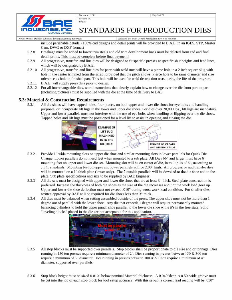
5.3: Material & Construction Requirements 5.3.1 All die shoes will have tapped holes, four places, on both upper and lower die shoes for eye bolts and handling
purposes, or incorporate lift lugs in the lower and upper die shoes. For dies over 20,000 lbs., lift lugs are mandatory.
Upper and lower parallels must not interfere with the use of eye bolts when handling or flipping over the die shoes.
Tapped holes and lift lugs must be positioned for a level lift to assist in opening and closing the die.
5.3.2 Provide 1” wide mounting slots on upper die shoe and similar mounting slots in lower parallels for Quick Die
Change. Lower parallels do not need feet when mounted to a sub plate. All Dies 66” and larger must have 6
mounting feet on upper and lower die set. Mounting slot will be on center of die, in multiples of 6”, according to
J.I.C. standards. Mounting feet on upper and lower parallels will be 2.00” high. All progressive and transfer dies
will be mounted on a 1” thick plate (lower only). The 2 outside parallels will be doweled to the die shoe and to the
plate. Sub plate specifications and size to be supplied by BAE Engineer.
5.3.3 All die sets must be designed with upper and lower die shoes that are at least 3" thick. Steel plate construction is
preferred. Increase the thickness of both die shoes as the size of the die increases and / or the work load goes up.
Upper and lower die shoe deflection must not exceed .010" during worst work load condition. For smaller dies,
written approval by BAE will be required for die shoes less than 3" thick.
5.3.4 All dies must be balanced when setting assembled outside of the press. The upper shoe must not be more than 1
degree out of parallel with the lower shoe. Any die that exceeds 1 degree will require permanently mounted
balancing cylinders to hold the upper punch shoe parallel to the lower die shoe while it's in the free state. Solid
"leveling blocks" placed in the die are not acceptable for this application.
5.3.5 All stop blocks must be supported over parallels. Stop blocks shall be proportionate to die size and or tonnage. Dies
running in 150 ton presses require a minimum diameter of 2”. Dies running in presses between 150 & 300 ton
require a minimum of 3” diameter. Dies running in presses between 300 & 600 ton require a minimum of 4”
diameter, supported over parallels.
5.3.6 Stop block height must be sized 0.010" below nominal Material thickness. A 0.040"deep x 0.50"wide groove must
be cut into the top of each stop block for tool setup accuracy. With this set-up, a correct lead reading will be .050"
Document: I12.01 Page 6 of 20
Revision: 001
Subject:
STANDARDS FOR PRODUCTION DIES Process Owner: Director- Advanced Tooling Engineering & Services Approved By: Mark Doetsch Management Rep/ Vice President
5.3.7 Parallels or riser blocks must be mounted above and below all forming, trimming, and nitrogen units.
5.3.8 Provide riser blocks and parallels to maintain shut heights and feed lines as determined by B.A.E. engineer.
5.3.9 For all dies, upper and lower die shoes will be of steel (preferred construction) or cast Iron construction. If a cast
die-set is approved by BAE, all cast die-sets for thicker or high strength & dual phase parts must be made from
D4512/NAAMS material. For thinner, mild steel parts, the cast die-sets must be made using a minimum of
G3500/NAAMS material. Incorporate a minimum of four ball bearing guide pins, with maximum cage engagement
and one pin offset. Heeled die sets where applicable will be used. Use of solid pins and bushings require approval in
writing at the die design review.
5.3.10 Line dies - upper and lower die shoes will be of steel or cast iron construction. Four post ball bearing guidepost on
trim and pierce operations. Note: Volume, size may dictate variation to above. Vendor to note any deviation on
quote. Heeled die sets where applicable will be used. Die sets using solid pins and bushings require approval in
writing at the die design review.
5.3.11 All line dies to have adequate gauging to produce a repeatable part. Die will be fool proofed to prevent improper
insertion of part/blank into gauging.
5.3.12 Stock guide lifters will be designed using Dadco Micro Nitrogen Lifters Series SLN when feasible. All lifters must
use nitrogen cylinders. Die springs are not allowed for lifter systems.
5.3.13 Stamp or etch all die sections with detail number, material type and heat treat data. Stamp the die shoe or riser next
to the detail with the corresponding detail number.
5.3.14 Stock guides at entrance end of die to be a minimum of 6" to 8” long and doweled after tryout.
5.3.15 All die sections will have jackscrews for easy removal of all sections. Details weighing 20 lbs. or more must have
handling holes that are positioned for balanced lift of the detail (strippers, pads, parallels, cams, etc.).
5.3.16 Pull dowels are required in BAE dies. Blind dowel holes are not allowed. Drill through details, die shoes, etc. with
reamer drill to aid in the removal of broken dowels. For trim sections, dowel locations are preferred in line. Dowels
are to be close slip-fit in punch and die sections, and light press fit in die shoes & risers.
5.3.17 Use standard Moeller heavy duty punches and buttons for mild steel parts up to 4mm thick. For thicker mild steel
and HSLA materials that are 080 KSI or higher and over 2.00mm thick, use heavy duty headed punches (Dayton's
TuffPunch or Moeller Manufacturing's DuraPunch) .
5.3.18 Slug Control die buttons must be used to pierce all holes. Wire burned pierce blocks (plates) are acceptable when
weak conditions exist or holes are too close together to mount buttons. Custom pierce plates must be approved at the
die design.
5.3.19 Die buttons must be used as pilot receivers with metal thickness clearance per side where conditions allow. Pilot
button must be keyed and retained and ¼-20 socket head cap screw used to retain key.
5.3.20 Pilots to be a minimum of .500 diameter / 13mm diameter unless conditions dictate otherwise.
5.3.21 First pilot must be mounted to the upper shoe for pilot release (don't use a stub pilot in the upper pad or lower detail).
5.3.22 Holes with close tolerance true position (TP of 0.50mm or less) must be pierced at same time.
Document: I12.01 Page 7 of 20
Revision: 001
Subject:
STANDARDS FOR PRODUCTION DIES Process Owner: Director- Advanced Tooling Engineering & Services Approved By: Mark Doetsch Management Rep/ Vice President
5.3.23 Pierce buttons and punches to rest on hardened surfaces. Pierce button retainers shall be one piece construction and
thru hardened to prevent shims from moving and buttons from sinking. Use 6150 material and hardened to Rc 54/58.
Buttons shall be slip fit in retainer and held in using keys. Keys must be held in by ¼-20 SHCS minimum. Use "True
set" retainers for individual punches when "cluster" or "gang" style retainers are not needed.
5.3.24 Pierced holes with a true position of 0.50 mm or less must use heavy duty gang retainers at 2” thick. Punch retainer
shall be thru hardened and punches must rest on hardened backing plate ¼” thick min. The backing plate must be
attached to the retainer using ¼-20flat head or low profile screws.
5.3.25 When cutting 080KSI or lower steel that is 2mm thick or less, all pierce punches with point diameters larger than
.250" must have shedder pins to prevent slug pull back in the tool. Don't use shedders in punches that have a point
diameter of .250" or less.
5.3.26 All working extrusion punches and buttons will be vented and Titanium Nitrate coated. If the extrusion is to be
tapped, it must have a coined chamfer on the tap exit side of the extrusion to eliminate ring burrs.
5.3.27 All pierce nut units are to be purchased with the electronic sensors built into the unit where applicable.
5.3.28 Cutting, flanging, and forming steels for material 080 KSI and less will be made of D2 steel unless otherwise agreed
to by B.A.E. engineering in writing. Other steels used (i.e. Keepers, filler block and strippers, etc.) will be
appropriate to its application.
5.3.29 All forming is to be completed before piercing. Exceptions must be approved in writing by BAE's Engineering Dept.
5.3.30 All forming and re strike details, upper and lower, will be designed for adjustability to accommodate stock variation.
5.3.31 All flange and forming details that could cause galling or scoring (i.e. flange steels, draw forms, binder pads, etc.)
must be coated or treated. BAE required process is ION Bond MOST.
5.3.32 All form, flange, cam-pierce and trim details where thrust is a factor will be keyed and or heeled to suit. Keys must
be pocketed in die shoe and lock in the detail from the outer edges. Details that have Key Ways machined into them
tend to break more easily. If individual details are keyed for side thrust but not internally heeled, the upper & lower
die shoes must be heeled to prevent wear on the pins and bushings.
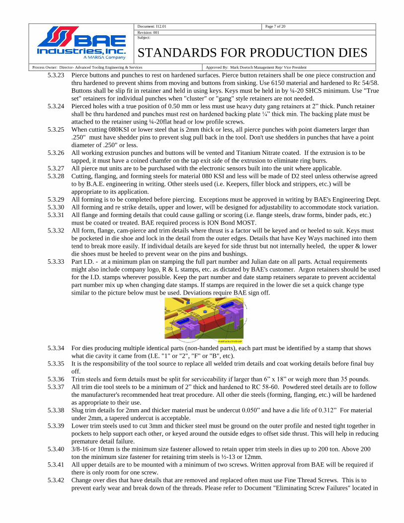
5.3.33 Part I.D. - at a minimum plan on stamping the full part number and Julian date on all parts. Actual requirements
might also include company logo, R & L stamps, etc. as dictated by BAE's customer. Argon retainers should be used
for the I.D. stamps wherever possible. Keep the part number and date stamp retainers separate to prevent accidental
part number mix up when changing date stamps. If stamps are required in the lower die set a quick change type
similar to the picture below must be used. Deviations require BAE sign off.
5.3.34 For dies producing multiple identical parts (non-handed parts), each part must be identified by a stamp that shows
what die cavity it came from (I.E. "1" or "2", "F" or "B", etc).
5.3.35 It is the responsibility of the tool source to replace all welded trim details and coat working details before final buy
off.
5.3.36 Trim steels and form details must be split for serviceability if larger than 6” x 18” or weigh more than 35 pounds.
5.3.37 All trim die tool steels to be a minimum of 2” thick and hardened to RC 58-60. Powdered steel details are to follow
the manufacturer's recommended heat treat procedure. All other die steels (forming, flanging, etc.) will be hardened
as appropriate to their use.
5.3.38 Slug trim details for 2mm and thicker material must be undercut 0.050” and have a die life of 0.312” For material
under 2mm, a tapered undercut is acceptable.
5.3.39 Lower trim steels used to cut 3mm and thicker steel must be ground on the outer profile and nested tight together in
pockets to help support each other, or keyed around the outside edges to offset side thrust. This will help in reducing
premature detail failure.
5.3.40 3/8-16 or 10mm is the minimum size fastener allowed to retain upper trim steels in dies up to 200 ton. Above 200
ton the minimum size fastener for retaining trim steels is ½-13 or 12mm.
5.3.41 All upper details are to be mounted with a minimum of two screws. Written approval from BAE will be required if
there is only room for one screw.
5.3.42 Change over dies that have details that are removed and replaced often must use Fine Thread Screws. This is to
prevent early wear and break down of the threads. Please refer to Document "Eliminating Screw Failures" located in
Document: I12.01 Page 8 of 20
Revision: 001
Subject:
STANDARDS FOR PRODUCTION DIES Process Owner: Director- Advanced Tooling Engineering & Services Approved By: Mark Doetsch Management Rep/ Vice President
section 7.0 - "Additional Reference Material".
5.3.43 Only high quality screws meeting MIL specifications per the MIL-HDBK-57 standard are to be used. These are
generally produced in North America and Twain. Screws produced in other countries such as China that don't meet
the MIL standard tend to have quality issues due to poor heat treat applications.
5.3.44 At the strip review, BAE will confirm if the tooling is to be designed using English or Metric die construction.
5.3.45 To reduce early fastener failure please refer to the charts for Through-Hole Preparation and Drill and counterbore
sizes English and Metric, located in section 7.0 - "Additional Reference Material".
5.3.46 Break all non functioning sharp edges and corners for safe handling.
5.3.47 Misumi, Sanko Oilless and Anchor Danly purchased cams are acceptable as long as they are not the "box" style cam.
Also acceptable are custom built cams that are approved by BAE during the Die Design Review.
5.3.48 Custom cams shall be constructed of 6150, 4150, 0-1 or D2 material and hardened. Steel on steel construction is not
acceptable. Wear plates, gibs, cam drivers and heel plates will be aluminum bronze self lubricating. Cam slide wear
plate to extend beyond the cam in the home position. This will insure accurate and repeatable hole location and
improve the strength of the cam in the event of a miss hit.
5.3.49 Cam return blocks extending under the cam shall be designed as shown below. The cam has a wire EDM hole
burned thru it, with the rectangular return detail light press fit into the cam and welded at the top. Return blocks that
are screwed in place tend to come loose in production and are not allowed. All cam pads must incorporate nitrogen
cylinders. Individual spring pads are not allowed.
Screwed on return blocks and springs in pads are not acceptable.
5.3.50 The Die shop is responsible for lubrication manifolds, sprayer head assemblies, and quick release fittings. Mounting
locations will be determined at the die review. BAE will run the nylon tubing for the sprayers after the die arrives at
BAE. To maintain consistent pressure there will be a maximum of four die lube manifold blocks per die, with a
maximum of 3 die mounted sprayer assemblies coming off each manifold block. The die manifold blocks must be
accessible yet protected from Hi-Lo and crane handling damage.
Document: I12.01 Page 9 of 20
Revision: 001
Subject:
STANDARDS FOR PRODUCTION DIES Process Owner: Director- Advanced Tooling Engineering & Services Approved By: Mark Doetsch Management Rep/ Vice President
5.3.51 For Extrusion Dies, the 1st, 2
nd and 3
rd Extrusion Punch details must be designed for easy height adjustment while in
the press. Extrusion dies must be built with extrusion facing downward (buttons mounted on the lower die shoe and
punches mounted on the upper punch shoe). Add air vents to extrusion punches and buttons anywhere fluid might
be trapped to eliminate material thinning caused by hydraulic pressure.
5.3.52 All dies must be equipped with Strip Alignment Aids, such as Goal Posts. Strip must be able to feed through the first
stock rail and all the way to the end of the die, locating between two "Goal Posts" to insure strip is aligned properly
in the die. An alternative is to use "goal posts" on top of the first stock rails and at the end of the die, which will
allow the strip to be run over top of all the lower details.
5.3.53 Details having movement that might be impeded by trapped air or lubricant must have proper venting & drainage
(I.E. - guide pin bushings covered by parallels, extrusion buttons that fill with lubricant, nitrogen cylinders that could
become submerged in lubricant, etc.).
5.3.54 Guide pins & bushings must be engaged by at least 1 1/2 times the pin diameter and heel blocks must be engaged by
at least 1" before any die activity begins (cutting, forming, tapping, etc.). Whenever possible, size the length of the
pins & bushings so they stay engaged at the top of the stroke.
5.4: Pads and Pressure System Requirements 5.4.1 Use Dadco nitrogen cylinders in the tooling. Any other brand must be interchangeable with Dadco and will require
B.A.E. engineering approval.
5.4.2 Nitrogen cylinders shall not be left loose in holes drilled in the shoe or parallels.
5.4.3 All nitrogen cylinders shall be retained using the suppliers mount methods only. Screws from the back side or steel
mounting flanges are acceptable. The rubber style that rely on friction to hold the cylinder are not acceptable
(coolant breaks down the rubber).
Document: I12.01 Page 10 of 20
Revision: 001
Subject:
STANDARDS FOR PRODUCTION DIES Process Owner: Director- Advanced Tooling Engineering & Services Approved By: Mark Doetsch Management Rep/ Vice President
5.4.4 All forming or pressure pads will use either self-contained nitrogen cylinders that are hosed together and have a
pressure gage, or nitrogen manifolds to-suit. Any deviation will require written approval from the BAE Die
Engineer. Forming pressures for parts using hosed or nitro manifolds must be permanently stamped on dies.
5.4.5 For applications where self-contained "drop in" nitrogen cylinders are used, they must be at maximum pressure or
hosed together with a pressure gage showing the reduced pressure required.
5.4.6 When forming with a nitrogen pad, pressure should be a minimum of 25% greater than what is needed to create the
desired form. Drop-in cylinders must be hosed together with a pressure gage and have the required pressure stamped
on the die. Forming with the pad requires B.A.E. approval at the strip review.
5.4.7 Guard all exposed nitrogen lines, air hook ups, nitrogen cylinders, etc. from Hi Lo forks to prevent damage while
handling or setting in the press.
5.4.8 Any surface where nitrogen cylinder rod makes contact must be hardened to prevent wear. Hardened pucks mounted
to soft boiler plate strippers are an acceptable alternative.
5.4.9 All upper stripper plates ( pads) must be a minimum of 2” thick. Windows should be a minimum of 1" thick.
5.4.10 Keepers used for strippers will be of one-piece construction and be at least 6” in length unless die or part design
dictates otherwise. Use pins and bushings to suit the stripper size.
5.4.11 Standard Lifters need to be approved by BAE engineering. Use of Standard Lifter Products is only acceptable when
designed using the following stripper retaining requirements: Dies for presses 200 ton or below use a minimum of
GK180 with Locking Collar, 220 to 400 ton used a minimum of GK205 with Locking Collar, above 400 ton GM
Standard GK210GM with Locking Collar. Note that the amount of retaining screws shall equal what is used for
Standard Pin and Bushing construction. Standard Lifter Keepers must not be used anywhere side loading can occur.
5.4.12 Hardened windows will be used on the stripper pad wherever contact is made to the part. Stripper windows shall be
constructed of 6150 material and hardened to Rc 54/56. In cases where fully hardened windows might break, flame
hardened windows can be substituted with BAE's written approval.
5.4.13 Strippers must have “removable windows” to access and easily remove all punches, whether ball lock or solid, from
a die that's set up in the press. A minimum of ½-13 SHCS must be used to retain stripper windows. Exceptions must
be in writing and approved by BAE Engineering.
5.4.14 All draw beads are to be inserted to aid in their refurbishment. This applies for binder pads and solid form details.
5.5: Feeding/Ejecting Requirements 5.5.1 All progressive dies will be equipped with start triggers and or sightlines for starting the strip. Tool shall be designed
with the starting position in a location to produce a full stamping, where possible. In the event this cannot be
accomplished make tooling engineer aware of this in writing, and mount a sample of the partial part or loose scrap on
the die.
5.5.2 Parts and scrap must cleanly eject from progressive dies. Parts that are not common must exit separately, and can't be
mixed with scrap. Install chutes to accomplish clean part ejection.
5.5.3 Scrap must cleanly eject from line dies that are cutting material.
5.5.4 Hardened slug deflectors will be used in pierce posts to deflect pierce slug in all cam pierce dies.
5.5.5 All part chutes and / or scrap chutes that extend outside the die set must be removable. They must be securely
screwed in place - welding is not acceptable. All part and scrap chutes must be made from steel and have a minimum
thickness of 3/16".
5.5.6 When mounting lower parallels, the distance between any parallels where scrap is ejecting must be sized
according to the following:
Less than 10": Sized to the nearest whole inch, plus 1/4 inch (ex: 2-1/4", 3-1/4", 4-1/4", etc).
10" and above: Sized to the nearest EVEN whole inch, plus 1/4 inch (ex: 10-1/4", 12-1/4", 14-1/4", etc).
This will provide clearance for our standard shaker chutes to work.
5.5.7 Maximum scrap length must be limited to 6" max for small bed presses and 10" max for the large bed presses. In
addition, the lower parallel height should be taller than the longest piece of scrap produced by the die.
5.5.8 Nitrogen cylinders used for lifters or lifter bars must be designed to eliminate side thrust on the cylinder rod as the
strip advances. The lifter bars must also push down level, even when starting a strip through the die.
5.5.9 Compressed air blow-off' nozzles are not to be used for scrap or part removal unless absolutely necessary, and only
with BAE's written permission.
Document: I12.01 Page 11 of 20
Revision: 001
Subject:
STANDARDS FOR PRODUCTION DIES Process Owner: Director- Advanced Tooling Engineering & Services Approved By: Mark Doetsch Management Rep/ Vice President
5.6: Sensor Requirements 5.6.1 Sensor protection must be incorporated into all die designs. A minimum of one positive stop with a built-in short
feed sensor at the beginning of the die, tapped mounting holes for a junction box, tapped holes for mounting a bridge
at the end of the die, and wire channeling will be required from the die shop on all tools. The wire channels must
have steel covers and go from the junction box to every sensor in the tooling, including to the exit end of the die
where BAE will be installing anti-buckle and part out sensors (reference drawings at the end of section 5.8).
5.6.2 In addition, all cams will require sensor mounts to detect that they've fully retracted, and transfer dies must have
provisions for sensors in each station to ensure that the part is present and correctly seated in the station. At the strip
review additional sensor mounting brackets and tapped holes may be requested as directed by BAE's Sensor
Technician.
5.6.3 BAE will install the junction box, bridge, all sensors, and wiring once the tooling is received in our plant.
5.6.4 All cables for electrical devices, along with all lube lines and airlines must be designed for quick disconnect and
protected against damage using proper channels, covers, and shields.
5.6.5 All dies must have channels machined into the upper surface of the lower die shoe for sensor wiring. The location of
the main channel and junction box will be reviewed and approved at the Die Design Review. Channels on the
underside of the shoe will require BAE's approval.
5.6.6 For most dies, a 5/8" wide x 5/8" deep channel will accommodate the necessary wiring (approximately 4 wires). As
more sensors are required, the channel size will need to be increased to accommodate the additional wiring.
5.6.7 Channels must not have sharp corners that can cut the wiring. Machine a 1/2" or larger radius on every channel
corner that a wire will wrap around.
5.6.8 Channels must extend underneath the junction box and sensor mounts (don't stop next to them - this will leave
wiring exposed).
5.6.9 Provide 1/2" drainage holes along all wire channels where die lubricant fluid has the potential to collect, with a
maximum distance of 24" between drain holes.
5.6.10 Channel cover plates are required over wire channels. Make the covers out of steel that is at least .080" thick and
fasten to the die set with 1/4-20 socket head cap screws that are spaced a maximum of 12" apart. All covers must be
easily removable without having to disassemble the die.
5.6.11 Tapped holes are required on the front and back edge of the die shoe at the exit end of the shoe. These are used to
mount the bridge that holds the anti-buckle and part out sensors. Most dies will require (4) 1/2" tapped holes on
each surface. For extra large or small dies, the size and number of tapped holes will be altered to-suit. The mounting
pattern must be discussed and approved during the die review process.
5.6.12 Four 1/4-20 tapped mounting holes for a Hoffman junction box, cat.#A604SC, are required on each die. The
mounting holes must be positioned from the edge of the die shoe per the reference drawing provided. The box
location also needs to be where it doesn't interfere with lifting chain hooks or swivel eyebolts when picking up or
flipping over the die set.
5.6.13 The die must include a positive stop with built in sensor at the beginning of the die, based on BAE's concept design
(see reference drawing). The swivel type that pivots on a shoulder bolt is not acceptable.
5.6.14 When multiple parts are exiting in the same area of the die, the part exit chutes must be designed to separate the parts
so they can be sensored and packaged individually. Scrap is never allowed to exit using the same chute as the part exit
chute.
5.6.15 Reference Drawings for die sensor installation:
Document: I12.01 Page 12 of 20
Revision: 001
Subject:
STANDARDS FOR PRODUCTION DIES Process Owner: Director- Advanced Tooling Engineering & Services Approved By: Mark Doetsch Management Rep/ Vice President
Document: I12.01 Page 13 of 20
Revision: 001
Subject:
STANDARDS FOR PRODUCTION DIES Process Owner: Director- Advanced Tooling Engineering & Services Approved By: Mark Doetsch Management Rep/ Vice President
Document: I12.01 Page 14 of 20
Revision: 001
Subject:
STANDARDS FOR PRODUCTION DIES Process Owner: Director- Advanced Tooling Engineering & Services Approved By: Mark Doetsch Management Rep/ Vice President
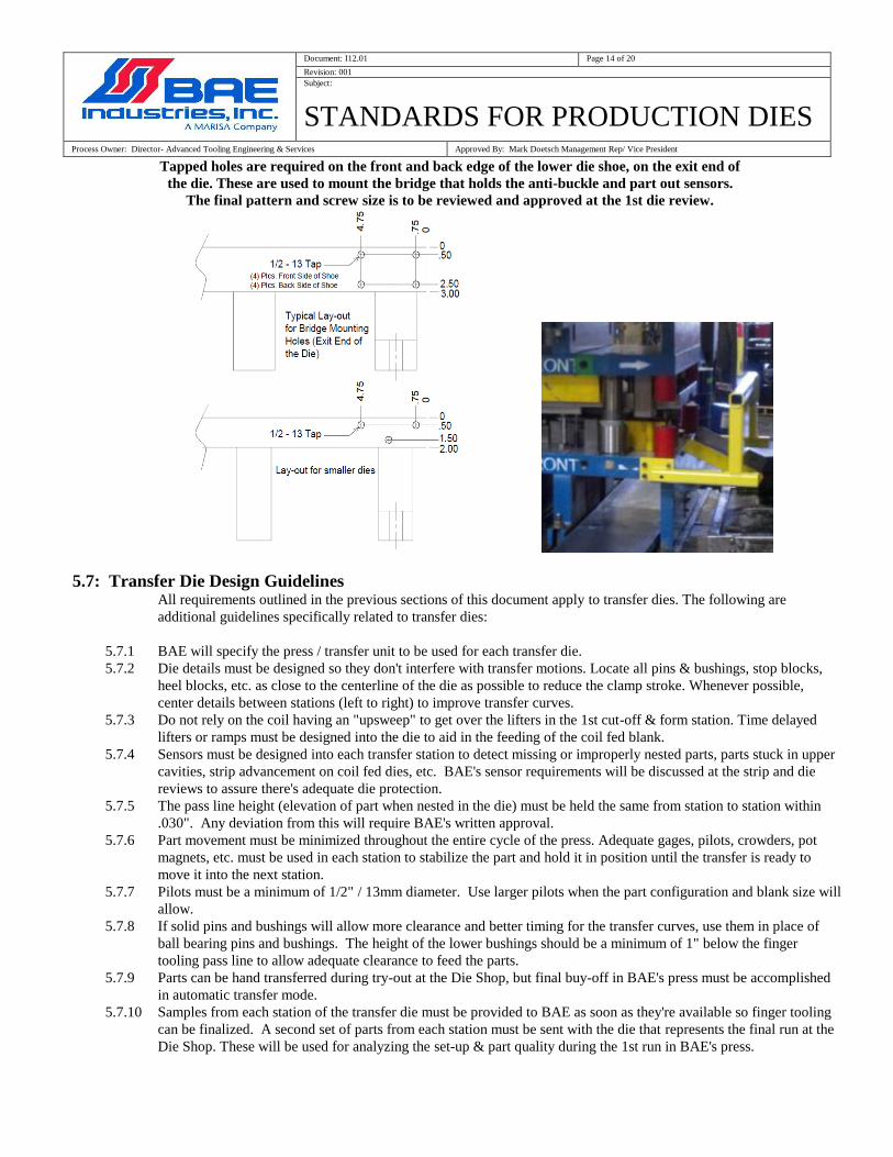
Tapped holes are required on the front and back edge of the lower die shoe, on the exit end of
the die. These are used to mount the bridge that holds the anti-buckle and part out sensors.
The final pattern and screw size is to be reviewed and approved at the 1st die review.
5.7: Transfer Die Design Guidelines All requirements outlined in the previous sections of this document apply to transfer dies. The following are
additional guidelines specifically related to transfer dies:
5.7.1 BAE will specify the press / transfer unit to be used for each transfer die.
5.7.2 Die details must be designed so they don't interfere with transfer motions. Locate all pins & bushings, stop blocks,
heel blocks, etc. as close to the centerline of the die as possible to reduce the clamp stroke. Whenever possible,
center details between stations (left to right) to improve transfer curves.
5.7.3 Do not rely on the coil having an "upsweep" to get over the lifters in the 1st cut-off & form station. Time delayed
lifters or ramps must be designed into the die to aid in the feeding of the coil fed blank.
5.7.4 Sensors must be designed into each transfer station to detect missing or improperly nested parts, parts stuck in upper
cavities, strip advancement on coil fed dies, etc. BAE's sensor requirements will be discussed at the strip and die
reviews to assure there's adequate die protection.
5.7.5 The pass line height (elevation of part when nested in the die) must be held the same from station to station within
.030". Any deviation from this will require BAE's written approval.
5.7.6 Part movement must be minimized throughout the entire cycle of the press. Adequate gages, pilots, crowders, pot
magnets, etc. must be used in each station to stabilize the part and hold it in position until the transfer is ready to
move it into the next station.
5.7.7 Pilots must be a minimum of 1/2" / 13mm diameter. Use larger pilots when the part configuration and blank size will
allow.
5.7.8 If solid pins and bushings will allow more clearance and better timing for the transfer curves, use them in place of
ball bearing pins and bushings. The height of the lower bushings should be a minimum of 1" below the finger
tooling pass line to allow adequate clearance to feed the parts.
5.7.9 Parts can be hand transferred during try-out at the Die Shop, but final buy-off in BAE's press must be accomplished
in automatic transfer mode.
5.7.10 Samples from each station of the transfer die must be provided to BAE as soon as they're available so finger tooling
can be finalized. A second set of parts from each station must be sent with the die that represents the final run at the
Die Shop. These will be used for analyzing the set-up & part quality during the 1st run in BAE's press.
Document: I12.01 Page 15 of 20
Revision: 001
Subject:
STANDARDS FOR PRODUCTION DIES Process Owner: Director- Advanced Tooling Engineering & Services Approved By: Mark Doetsch Management Rep/ Vice President
5.8: Design Guidelines for Parts used in Mechanism Assemblies 5.8.1 On parts with working cam surfaces that rely on a die cut trim edge, the working area must be pre-trimmed and then
shaved to give more burnish and accuracy to the trim line. To meet the true position and profile tolerancing of the
part, the shave operation must be done in the same station that pierces all critical holes for the cam mechanism.
5.8.2 Critical embosses will require adjustable upper and lower re-strike details to maintain the emboss height and flatness
requirements. Examples of critical embosses are those that hold the main pivot, detent pivot, or are a mating /
support surface for the Mechanism Assembly.
5.8.3 Any parts with off-set surfaces having tight profile tolerances will require provisions to re-strike those areas to meet
flatness, parallelism, & profile call-outs.
5.8.4 For parts with tightly toleranced 90 degree bends or sidewalls, incorporate adjustable form steels and a means to
over bend the feature to allow for spring back.
5.9: Tool Evaluation & Acceptance Requirements 5.9.1 A three phase part approval process will be used to confirm the quality of the parts.
Phase one buy-off - The Die Shop is to provide BAE with a six piece CMM lay-out on parts from each die
cavity. The lay-outs must check the ENTIRE part including trim lines, forms, hole locations, customer buy-
off points, etc. to verify that the part meets all part print specifications.
Phase two buy-off - After BAE approves the phase one lay-outs, the die shop can schedule the 1,000 piece
run at their facility. During the run, 30 pieces from each die cavity are to be randomly chosen for a CMM
lay-out. The Die Shop must check all buy-off points (provided by BAE) and part print feature control
frames to prove out part capability. BAE personnel must be present for this run. After the lay-outs are
forwarded to BAE and approved, the die can be finalized and shipped to our plant. Note that the tooling
ship date must be on or before the delivery date (due date) agreed to on BAE's tooling purchase order.
Phase three buy-off - BAE's home line press will be scheduled for the phase 3 run after the die, steel, gages,
Document: I12.01 Page 16 of 20
Revision: 001
Subject:
STANDARDS FOR PRODUCTION DIES Process Owner: Director- Advanced Tooling Engineering & Services Approved By: Mark Doetsch Management Rep/ Vice President
spare details, etc. arrive at our plant. All dies must perform in automatic mode, running at BAE's quoted
strokes per minute, for a maximum of 2,000 consecutive hits or one day's production (whichever is greater).
If there are any issues with the tooling during the phase 3 buy-off process, it will be the responsibility of the
die shop to correct them (I.E. - sticking lifters, slugs not exiting, parts getting caught in the cut-off station,
etc.). Qualified Die Shop personnel must be present at BAE to support the run-at-rate.
BAE will randomly collect thirty parts from each die cavity during the phase 3 run-at rate and lay them out on the
CMM. All parts must meet a minimum of 1.67 Ppk / 1.33 Cpk, or meet part print specifications if more stringent
requirements are specified.
5.9.2 All CMM lay-outs are to be submitted as follows:
Use the PC Dmis program provided by BAE or an approved PC Dmis program using BAE's buy-off points
if created by a third party.
Parts made from every cavity in the tooling must be inspected.
A roadmap must be provided with each lay-out. The CMM data must show the nominal dimension,
tolerances applied to the dimension, and how each dimension meets BAE's Ppk / Cpk requirements.
Any dimensions not meeting the specifications must have an action plan with timing to make them capable.
5.9.3 All tools must be capable of making parts that pass on the BAE production gage and pass capability per the criteria
listed above.
5.9.4 The Die Shop is responsible for the tooling and part quality until a successful phase 3 run has been completed. Until
the tooling is bought off, all die issues, part quality issues, and trucking are the responsibility of the Die Shop. If the
Die Shop can't correct the issues in a timely manner to protect the PPAP date, the work may be outsourced and a
debit memo issued to the original die source for the cost of the work.
5.9.5 Die Shop personal are required to wear safety glasses, ear protection, proper foot wear and Visitors Badge per BAE
safety manual while in BAE’S plants, and adhere to Document HS-P05 Visitor and Contractor EHS Requirements
Manual.
5.9.6 B.A.E. will sign off tools when all above conditions have been met.
5.9.7 Before Tool can be invoiced to BAE for payment the following conditions must be met:
BAE Tool Approval Forms must be completed and signed off
Spare Details have been delivered to BAE
Tool designs and Detail prints in electronic format ( IGES,DWG,DXF ) or Master Cam have been received
by BAE that are100% up to date (updated to show all changes made during try-out).
5.10: Shipping Requirements 5.10.1 All dies will have the B.A.E. job number stenciled on four sides of the upper and lower die shoe. Stencil the upper
die weight on the upper shoe four sides and the total die weight on the lower die four sides. In addition, stamp the
following information on the front face or front top surface of the lower die shoe: part number, part name, stock
width, pitch, material thickness, shut height, and weight. 5.10.2 Each die must be marked or tagged per the Customer's requirements for "property of" information, asset tags, etc.
5.10.3 Confirm that all dowels are the "pull dowel" style, and all screws have been installed with Blue Loctite #242 at final
assembly.
5.10.4 Reverse press tonnage (the release of the cutting forces) must not exceed 10% of the rated press tonnage. Any
deviation from this standard will require written approval from BAE.
5.10.5 A progressive die strip will be shipped with the die.
5.10.6 An operational part from every station of a transfer or line die will be shipped with each tool.
5.10.7 Photos of upper die, lower die, front view with die closed, strip, "property of" information, and any die tags to be
provided by the Die Shop. B.A.E. will assist if possible.
Document: I12.01 Page 17 of 20
Revision: 001
Subject:
STANDARDS FOR PRODUCTION DIES Process Owner: Director- Advanced Tooling Engineering & Services Approved By: Mark Doetsch Management Rep/ Vice President
6.0 Additional Reference Material
Document: I12.01 Page 18 of 20
Revision: 001
Subject:
STANDARDS FOR PRODUCTION DIES Process Owner: Director- Advanced Tooling Engineering & Services Approved By: Mark Doetsch Management Rep/ Vice President
Document: I12.01 Page 19 of 20
Revision: 001
Subject:
STANDARDS FOR PRODUCTION DIES Process Owner: Director- Advanced Tooling Engineering & Services Approved By: Mark Doetsch Management Rep/ Vice President
Document: I12.01 Page 20 of 20
Revision: 001
Subject:
STANDARDS FOR PRODUCTION DIES Process Owner: Director- Advanced Tooling Engineering & Services Approved By: Mark Doetsch Management Rep/ Vice President
7.0- Revision History
Garry Bartlett January 11, 2017 Revision #1 - Release of Standards. NOTE: Due to amount of changes and additions, the former "Standards for Production Dies" (Document I11.22 at Rev.17) was archived and a new number assigned to this replacement document .