Shell Australia Baker Hughes - 140-LT-1001A/B/C Leak Test Work Method Statement Originating Company Monadelphous Document Number 2000-410-OA-6039-00010 Revision Number 02 Discipline OA - Operations Document Type 6039 Document Status IFA – Issued for Approval Project Number Purchase Order Contractor Document ID Number 57242-7075-PRO-0002 Issue Date 13/10/2021 Author D.Munian Tag Numbers Area Code Security Classification Restricted Export Classification Number Non-US content - Non Controlled REVISION HISTORY Rev Revision Purpose Date Prepared/Reviewed by Approved by 01 Issued for Review 17/08/2021 D.Munian / Baker Hughes J.O’Brien 02 Issued for Approval 13/10/2021 D.Munian / Baker Hughes J.O’Brien
Transcript
Shell Australia
Baker Hughes - 140-LT-1001A/B/C Leak
Test Work Method Statement
Originating Company Monadelphous
Document Number 2000-410-OA-6039-00010
Revision Number 02
Discipline OA - Operations
Document Type 6039
Document Status IFA – Issued for Approval
Project Number
Purchase Order
Contractor Document ID Number 57242-7075-PRO-0002
Issue Date 13/10/2021
Author D.Munian
Tag Numbers
Area Code
Security Classification Restricted
Export Classification Number Non-US content - Non Controlled
REVISION HISTORY
Rev Revision Purpose Date Prepared/Reviewed
by Approved by
01 Issued for Review 17/08/2021 D.Munian / Baker
Hughes
J.O’Brien
02 Issued for Approval 13/10/2021 D.Munian / Baker
Hughes
J.O’Brien
Baker Hughes – 140LT-1001A/B/C Leak Test Work Method Statement
UI43134 Shell Prelude FLNG Maintenance and Modifications Services Technical Execution
Monadelphous Group Limited Division:
Maintenance and Industrial Services – Oil & Gas
Document number: 2000-410-OA-6039-00010
Contractor Document number: 57242-7075-PRO-0002
Revision: 02
Document owner: John O’Brien
Revision date: 13-Oct-21
Baker Hughes – 140LT-1001A/B/C Leak Test Work Method Statement UI43134 Shell Prelude FLNG Maintenance and Modifications Services
Monadelphous (MEA) have been engaged under 2000-010-UI43134-RFP-00269 to provide High Pressure Nitrogen Leak Testing activities on the new 140LT-1001A/B/C transmitter arrangement on V-14001 (Module 1P1). MEA have engaged Baker Hughes (BH) as subject matter experts for the works and MEA will oversee all equipment and personnel readiness. Given the critical nature of the scope Baker Hughes are to manage all Nitrogen filling activities in Darwin before loading on the Prelude Supply Vessel. The leak Test will be done during the Pitstop in October 2021 in conjunction with the Production Swivel 1 HPTL.
2 Roles and Responsibilities
2.1 Monadelphous (MEA)
- Manage Temporary Equipment Inspections.
- Manage all commercial implications of Sub-Contract with Baker Hughes (PPS).
- Onboard required personnel (including training, inductions, and relevant competencies).
- MEA Offshore Delivery Coordinator (ODC) to oversee Baker Hughes offshore.
2.2 Baker Hughes (PPS)
- Develop Safe Working Procedure and Test Packs.
- Manage any Hold Points for MEA/Shell sign off.
- Supply trained and competent personnel for onshore preparation and offshore execution.
- Coordinate bulk quantities of Nitrogen and Helium from Perth/Darwin to the Prelude Supply
Vessel and Darwin Port.
- Supply all Equipment, Materials and consumables for the Nitrogen High Pressure Leak Test of
the Swivel.
2.3 Shell/Technip
- Manage all Permit/ICCs offshore for Leak Test.
- Sign off relevant inspection points and approve Leak Test.
- Approve deliverables as listed below prior to mobilisation.
Copyright Baker Hughes Company. All Rights Reserved.
Project Summary
Baker Hughes PPS contracted to Monadelphous (MEA) for providing Nitrogen Services for Shell Australia on their Prelude FLNG asset, during Pitstop in October 2021.
Baker Hughes PPS will undertake Nitrogen Helium Leak test operations on the scopes identified by Customer in order to leak test all disturbed joints.
This document details the safe working practices that shall be implemented for helium leak detection operations on HP Separator Train 1 and Upstream swivel No1, and all other scopes requiring N2 Leak Testing.
Test Pack documents have also been developed containing specific instructions and checklists for each system nominated for leak testing.
The purpose of the documentation is to ensure leak testing is completed in a safe, accurate, and consistent manner.
Copyright Baker Hughes Company. All Rights Reserved.
Acronyms, Definitions, and Units of Measure
Acronyms and Definitions The following acronyms and definitions apply to this document and associated Test Packs:
Term Acronym Definition Downstream d/s Term and acronym used to describe leak locations
Design pressure PD A pressure not less than the pressure at the most severe condition of coincident internal or external pressure and temperature (minimum or maximum) expected during service.
Reference: ASME B31.3 Process Piping
Full scale deflection FSD Range on an instrument gauge
Gaseous nitrogen GN2 Acronym for gaseous nitrogen
Helium He Abbreviation for helium gas
High pressure HP Acronym for high pressure
Leak rate acceptance criteria
none Maximum allowable leak rate from a single source (expressed in units of standard cubic feet per year, scf/yr) above which a flange joint, threaded connection, or other component is deemed to be leaking and in need of repair
Leak source L# Flange joint, clamp type connector, man-way door, threaded connection, instrument tubing, or other system component capable of leaking
Liquid nitrogen LN2 Acronym for liquid nitrogen
Low pressure LP Acronym for low pressure
Maximum allowable working pressure
MAWP Maximum permissible pressure at the top of a vessel (or system) in its normal operating position at the designated coincident temperature.
MAWP is determined after construction of the vessel and is equal to or greater than the design pressure.
Reference: ASME BPVC Section VIII, Division 1
Maximum operating pressure
MOP Maximum pressure expected during normal system operation.
MOP is less than design pressure or MAWP.
Ref: API 520 Sizing, Selection, & Installation of Pressure Relieving Devices
Minimum design metal temperature
MDMT The lowest expected temperature in service at a corresponding MAWP; used for pressure vessel design purposes.
Reference: ASME BPVC, Section VIII – Division 1
Non-destructive examination / testing
NDE, NDT Method of testing and inspecting welds to ensure fabrication was completed correctly and contains no flaws
Non return valve NRV Abbreviation for non return valve (check valve)
Normal operating pressure NOP Normal pressure level for standard operating conditions.
NOP is less than MOP.
Over pressure protection system
OPPS Pneumatic or electronic device used to automatically shut down a nitrogen pump unit when a pre-set trip pressure is reached in order to protect a customer’s system from over pressurization.
Set pressure PPRV Pressure level that a pressure relief valve (PRV) or pressure safety valve (PSV) initially opens.
Note: ASME BPVC compliant PRVs have +/- 3% set pressure tolerance.
Test pressure PT Final test pressure a system is pressurized to
Trip pressure POPPS Pressure level that the PPS over pressure protection system (OPPS) is activated to automatically trip the nitrogen pump unit.
Upstream u/s Term and acronym used to describe leak locations
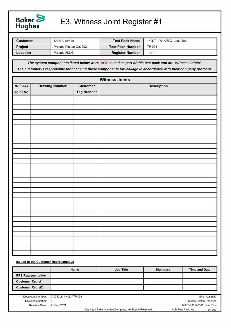
Witness joint W# Flange joint, threaded connection, or other potential leak source which forms part of a system but could not be tested for leakage.
Copyright Baker Hughes Company. All Rights Reserved.
Scope of Work
Test Systems Table 3 lists all the systems to be leak tested. The Test Packs were developed from the scope of work defined by the customer.
Test Pack Number
Test Pack Name Test Gas Required
sm3
Design / PSV Pressure
barg
Test Pressure
barg
OPPS Trip Pressure
barg
Temp. PRV Set Pressure
barg TP 001 HP Sep Train 1 and u/s Swivel 1 32000 89 75 81.6 N/A
*TP 002 Mercury Removal Unit 15000 75 67.5 68.8 71.6
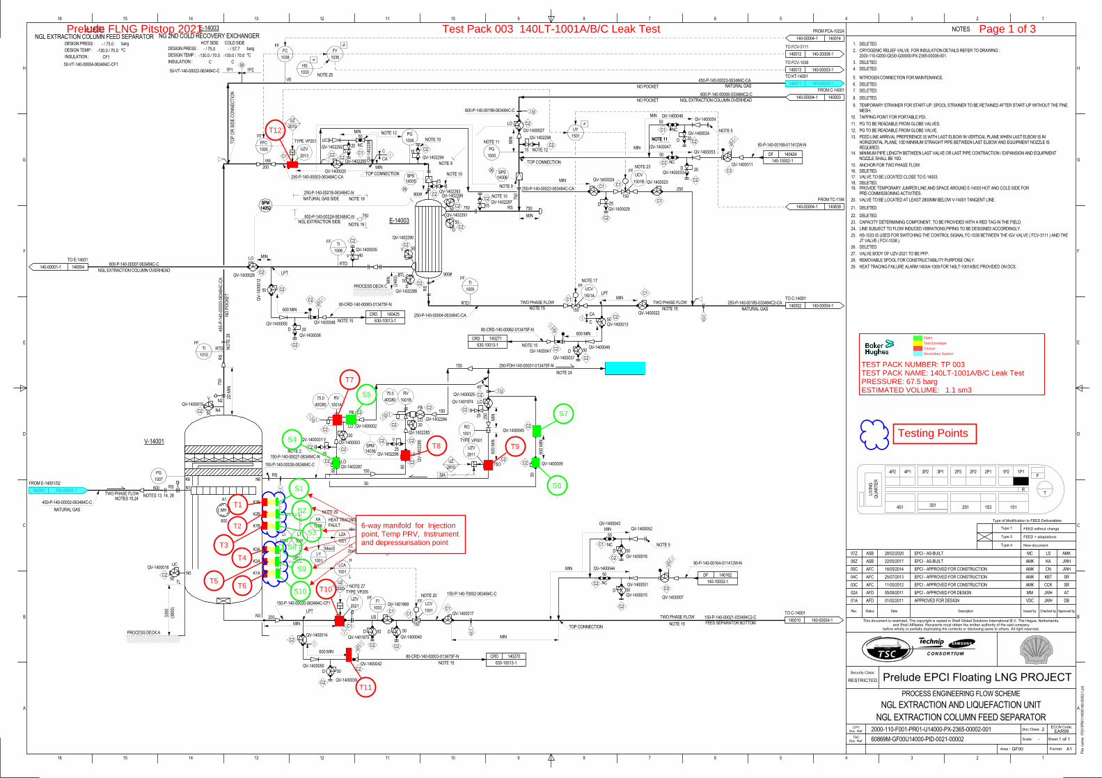
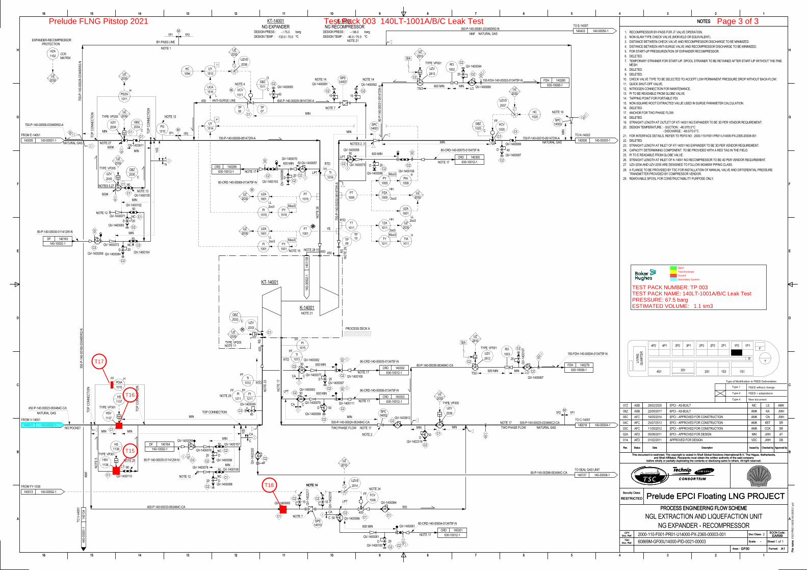
TP 003 140LT-1001A/B/C 15000 75 67.5 68.8 71.6
*TP002 - Mercury Removal Unit Leak Testing has been removed from Pitstop 2021 scope
Table 3: Test Systems
Test Requirements and Acceptance Criteria Helium leak testing operations shall be carried out in accordance with the following test parameters and acceptance criteria.
Requirement
Test Pressure Test pressure will be at system working pressure at client request.
Leak Test
Pressurize the system with a 1% helium / 99% nitrogen test gas mixture.
Check all potential leak sources identified for testing for the presence of helium gas using a calibrated helium leak detector.
Compare the quantified leak rate against the maximum allowable leak rate threshold and record the results.
Acceptance
Pressure to be maintained within 10% of the nominated test pressure for the duration of the test (top up if necessary and safe to do so).
Maximum allowable leak rate threshold from any single leak source not to exceed:
Valve glands and bonnets 50 scf / yr
Pig launcher and receiver doors 100 scf / yr
All other potential leak sources 20 scf / yr
For Swivel scope the Leak Rate has been accepted as 200 scf/ yr*
Leak rates BELOW the threshold are a PASS.
Leak rates ABOVE the threshold are a FAIL.
Each occurrence above the threshold shall be quantified and the details recorded.
All identified leak sources to be repaired and re-tested until one of the following conditions is met:
i. Leak free (no helium detected)
ii. Quantified leak rate is below the maximum allowable leak rate threshold
iii. The leak is accepted as a “Witness Joint” by the Customer Representative
*The acceptance criteria have been agreed after PS2 Swivel campaign in 2020
Table 4: Test Requirements and Acceptance Criteria
Copyright Baker Hughes Company. All Rights Reserved.
Management of Change All change requests initiated by either the Customer or PPS shall be dealt with promptly on a case-by-case basis in accordance with PPS management of change protocol. Each change request shall be formally documented on a change request form with the following information:
• Detailed description of the proposed change with reasons for implementation
• Expected deliverables such as documentation, personnel, equipment, or material resources
• Location for deliverables and date required
The proposed change shall then be assessed by the PPS Project Coordinator from a HSE, technical, commercial, and contractual perspective to determine:
• Technical feasibility and compliance with standard safe working practices for the service line
• Associated safety and environmental risks, and whether acceptable to both parties
• Quantification of additional resources requirements; personnel, equipment, materials, etc.
• Potential schedule and cost impact
• Whether the change request falls within the original contracted scope of work, or if a variation order and / or contract amendment is required
The results of the assessment shall be recorded by the PPS Project Manager. The information may be passed on to the PPS Operations Manager and other subject matter experts for further review, if considered necessary or required by PPS change management protocol.
The PPS Project Coordinator has the authority to approve and implement minor technical changes only. Major technical changes shall be approved by PPS area engineering. Any commercial or contractual changes shall be approved by the PPS Operations Manager prior to providing additional resources and implementing the change.
Approved changes shall be accurately documented before implementation to ensure all parties involved clearly understand the changes made and the impact on the project. For helium leak detection, document types could include new or changed job procedures, test packs, marked drawings, risk assessments, and equipment schematics. Any new or changed job documents shall be reviewed and approved by authorized PPS and Customer Representatives prior to implementing the changes.
Copyright Baker Hughes Company. All Rights Reserved.
Safety
Safety Induction, Site Orientation, and Permit to Work
Safety Induction and Permit Training All PPS crew members shall attend the customer’s safety induction training prior to carrying out any work. Any crew members nominated for requesting and / or signing permit to work documents shall also attend the customer permit to work training course.
Site Orientation Prior to undertaking any work, the PPS Project Coordinator (preferably accompanied by the Customer Representative) shall carry out a site orientation with the crew to ensure they are familiar with the work area. The orientation shall include visual inspection and confirmation of:
• Equipment lay down area
• Test systems and adjacent areas
• Emergency muster point location(s)
• Medical Centre, emergency showers, and first aid box locations
• Permit office location
• Waste disposal areas
• Other areas relevant to the test program
During the site orientation all crew members shall carry out a risk assessment review to identify any site specific risks or hazards not covered in the standard helium leak detection risk assessment. Refer to Section 5.2: Risk Assessment for further details of this process.
Permit to Work The PPS Supervisor is responsible for ensuring no work is carried out unless a valid permit to work is in place accurately describing the activities to be undertaken. The conditions of the permit shall be reviewed and discussed with the PPS crew so that all are aware of their responsibilities.
Copies of the permit shall be posted at the work site in accordance with the permit system instructions.
The permit shall be returned to the permit office and signed off upon completion of the work activities, or revalidated if work activities are expected to extend beyond the expiry time and date.
The customer’s permit to work system must prevent conflicting work activities from taking place in the same area at the same time. However, all members of the PPS crew shall be vigilant and immediately report any observed third party work activities with the potential to affect the planned testing program.
Copyright Baker Hughes Company. All Rights Reserved.
Risk Assessment
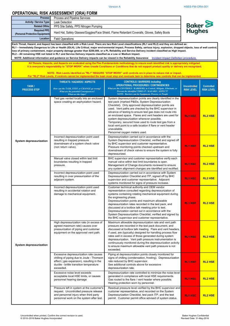
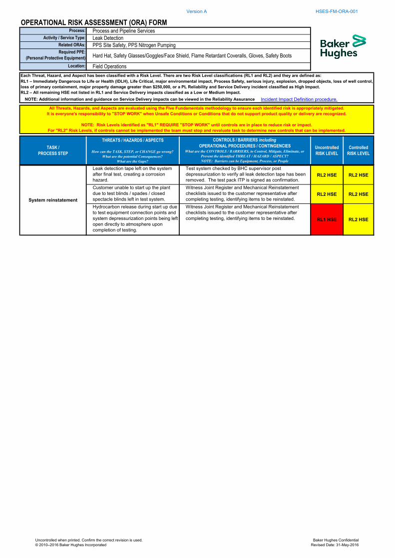
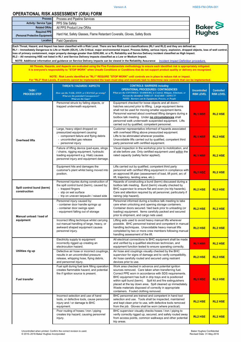
Standard Risk Assessment Appendix B contains standard risk assessments identifying the hazards and risks associated with helium leak testing operations, and the control measures to eliminate or reduce the risks to an acceptable level.
Site Specific Risks and Hazards The PPS crew shall carry out a work site assessment to identify any site specific risks or hazards not covered in the standard helium leak detection risk assessments.
Additional risks or hazards found shall be recorded on the PPS Safe to Perform (STP) form, along with proposed control measures for elimination or mitigation.
The PPS Project Coordinator shall review the standard risk assessment and the results of the site inspection at a Toolbox Talk meeting prior to undertaking any work. The Customer Representative and any other site personnel affected by the testing program shall be invited to attend.
Personnel shall be nominated to implement each proposed control measure for newly identified risks and hazards (PPS crew member, Customer Representative, or third party as appropriate).
The risk assessment and Toolbox Talk review process shall be repeated for each test.
Copyright Baker Hughes Company. All Rights Reserved.
Safety Meetings The following safety meetings shall be held and attended by the PPS Project Coordinator and leak testing crew:
• Project Safety Meetings (scheduled by the customer)
• Toolbox Talks
• Shift Handovers
Project Safety Meetings The PPS Project Coordinator and testing crew members shall attend project safety meetings upon invitation, and adequate notice, from the Customer Representative.
Safe to Perform (STP) – Toolbox Talks Prior to carrying out any leak testing work activities the PPS Project Coordinator or Shift Supervisor shall hold an initial Toolbox Talk meeting with all PPS crew members, Customer Representatives, and third party personnel affected by the helium leak detection test program.
Topics discussed shall include:
• Review of the leak testing scope of work
• Review of the standard risk assessment documents (see Section 5.2 and Appendix B)
• Personnel roles and responsibilities
• Site specific hazards and control measures not covered in the standard risk assessment
• PPE and safety equipment requirements
• Emergency response plans in the event of an incident or accident
• Incident, accident, near miss, and hazard reporting protocols
• Management of Change protocol (see Section 4)
• Any other relevant items
Rig up of equipment at the lay down area shall then commence after obtaining a permit for the work.
Subsequent Toolbox Talk meetings shall be held prior to undertaking the following tasks:
• System preparation, pressurization, leak testing, and depressurization for EACH TEST
• Rig down of equipment after completion of the final test
Minutes of each meeting shall be recorded on the PPS Safe to Perform (STP) form. All personnel present shall sign the attendance sheet to confirm understanding and agreement with all points discussed.
Copyright Baker Hughes Company. All Rights Reserved.
Shift Handovers A verbal and written handover shall be carried out at the end of each shift between the PPS incoming and outgoing Shift Supervisors, with a walk around the work site mandatory. The PPS crew shall also be in attendance to communicate any additional information to the oncoming crew.
Points discussed shall include:
• Work completed during the shift
• Work in progress
• Work planned for completion during the next shift
• Issues to be resolved
• Customer system status (customer system’s under pressure)
• Equipment and materials status
• Permit to work status
• Barriers and warning signs in place (if any)
• Procedural or system changes made under ‘Management of Change’ protocol (see Section 4)
• Safety issues or concerns
• Any other relevant information
The above information shall be recorded on a PPS Shift Handover form. This ensures a thorough handover is carried out with no ambiguity with respect to project status. The incoming and outgoing Shift Supervisors are both required to sign and date the shift handover form prior to commencement of work activities on the new shift.
Copyright Baker Hughes Company. All Rights Reserved.
Behavioural Safety The Baker Hughes enterprise HSE management system requires PPS personnel to pro-actively carry out visual inspections of their work areas and report any observed hazards, unsafe conditions, near misses, incidents or accidents. A summary of these policies is provided below.
Step Back 5 x 5 Baker Hughes Step Back 5 x 5 review is a self-evaluation risk management method that makes personnel stop and think about the task they are about to perform. Personnel are required to:
• Visually inspect the work area and surroundings
• Verify hazard controls have been implemented for the task to be carried out
• Identify any additional hazards and apply appropriate controls
• Record safety observations on the Baker Hughes SOS (Safety Observation System) card
• Stop work if appropriate controls cannot be applied (see below)
Observation & Intervention Card - (OIC) PPS personnel shall use Shell Observation and Intervention card to record any hazards observed during the Step Back 5 x 5 review. The card shall also be used to record Stop Work events.
OIC cards help communicate and report hazards before becoming potential incidents.
OIC cards are to be used as follows:
• Recognize and acknowledge others when we see a safe act or positive behavior
• Report any unsafe act or condition or near miss
• Complete and submit to PPS Supervisor or HSSE advisor
The PPS Project Coordinator shall collect the cards from crew members, review the data, and implement appropriate controls to rectify the hazardous condition reported.
Stop Work The Baker Hughes Stop Work policy empowers every individual with the responsibility and authority to stop work at any time when an observed unsafe condition or act might result in a HSE incident. The stop work protocol shall be explained to personnel during the site induction, and reiterated during Toolbox Talks.
Near Miss and Incident / Accident Reporting Any observed near miss, incident, or accident shall be reported and recorded in compliance with the customer’s and Baker Hughes reporting procedures.
In an emergency situation, PPS personnel shall follow the emergency response plan in Section 5.6 of this document. The plan shall be reviewed with personnel during a Toolbox Talk prior to commencing operations.
The PPS Project Coordinator shall review customer safety rules, site conditions, and safety data sheets (SDS) for all materials being handled to ensure the above PPE is adequate for the planned work activities. Data sheets shall be posted at the work site and / or test cabin for reference by the crew. Any additional PPE requirements identified shall be issued to the crew.
The PPS Project Coordinator shall determine whether inclement weather requires the use of insulated coveralls, zero hoods, wet weather clothing, or other specialty PPE.
Manual Handling Cranes and other lifting aids shall be used wherever possible to eliminate manual lifts of heavy, large and awkward shaped objects. However, manual lifting shall still be required of various equipment items.
All PPS crew members have attended training for correct manual handling techniques. All manual handling lifts shall be assessed before carrying them out, and help obtained from other crew members if an equipment item is considered too heavy, large, or awkward shaped for a single person. Equipment items that fall into this category for leak testing operations include helium gas booster pumps and over pressure protection systems (OPPS). The hazards associated with lifting these items are documented in the risk assessments contained in Appendix B, and shall be reviewed as part of a Toolbox Talk meeting prior to carrying out equipment rig up or rig down activities.
The project may also require crew members to carry out manual lifts of other heavy, large, or awkward shaped items for non-standard work activities. The PPS Shift Supervisor shall carry out an assessment of each lift, then discuss potential hazards and correct lifting techniques with the relevant crew members before the work is carried out.
Hand Tool Safety Hand tools are an integral part of the helium leak detection equipment rig up. Improper maintenance, selection, and use of hand tools can easily cause first aid or more serious injuries.
All PPS crew members have attended practical training in the correct selection, use, and maintenance of hand tools.
Copyright Baker Hughes Company. All Rights Reserved.
Working at Height Helium leak detection operations often require personnel to work at height. The PPS Shift Supervisor is responsible for identifying and assessing such activities and ensuring the appropriate safety resources are provided to the crew members.
Only certified scaffolding and / or ladders erected by qualified scaffolding personnel shall be used to access high points. Harnesses and lanyards may also be required. All safety equipment used shall conform to site standards and have appropriate certification.
Lighting The Customer Representative is responsible for ensuring adequate lighting for safe working is provided at both the PPS equipment lay down area and at all customer systems nominated for testing. The PPS Supervisor shall assess the lighting provided. A request may be made for additional lighting in critical areas if the standard lighting is considered to be unsafe for working.
Confined Spaces Confined spaces can be lethal, particularly when inert gases such as helium and nitrogen are being used at the work site. Potential inert gas releases include:
• Accidental release from storage (operator error)
• Loss of containment (equipment failure)
• Leaking joints under pressure
The PPS Shift Supervisor and Customer Representative are responsible for identifying any confined spaces within close proximity of the equipment lay down area or test areas. Any work activities involving entry into a confined space shall be done in strict accordance with site permit to work conditions and safety rules. Gas checks shall be carried out to ensure oxygen levels are safe for entry. Personal oxygen monitors shall be used. Emergency breathing apparatus (B.A. sets) shall be available at the confined space work area. A buddy system is also required. Under no circumstances shall personnel enter a confined space if the potential exists for nitrogen / helium gas to be present. If in doubt STOP the job.
Radio Communications Radio communications are a critical part of any leak detection process, particularly during system pressurization. Radios shall be provided in sufficient quantities to ensure all personnel associated with the testing program, including those nominated for patrolling the test exclusion zone perimeter, are in constant communication during the job. A clear, uninterrupted communication line on a dedicated channel shall be open at all times between the nitrogen pump Operator and PPS Shift Supervisor. If the equipment operator loses contact with the Supervisor at any time during the pressurising and leak testing phases, or there is third party interference on the channel, operations shall immediately be stopped and the communication problem investigated. Testing shall only recommence once communication lines are re-established.
Correct radio protocol shall be discussed at a Toolbox Talk meeting prior to carrying out pressurization and testing operations. The protocol requires any instructions issued by a PPS Supervisor to be repeated back by the recipient to acknowledge receipt and confirm their understanding.
Copyright Baker Hughes Company. All Rights Reserved.
Housekeeping Poor housekeeping is a frequent, and avoidable, cause of first aid or more serious injuries in the oil and gas industry. Good housekeeping shall be maintained at all times:
• Hoses / temporary piping not rigged up for test shall be placed in the equipment stores area
• Valves, fittings, and equipment spares shall be placed in dedicated storage bins
• Tools shall be placed in a secure toolbox within the stores area
• Instrumentation and PRVs shall be placed in dedicated transport cases in the stores area
• Helium leak detectors and ancillary leak detection equipment shall be placed in dedicated transport cases in the test cabin when not set up for testing
• PPS crew members shall check the equipment lay down area and test system areas on a regular basis to ensure they remain clean and tidy
Waste Material Any waste materials generated by PPS during the course of the leak testing program shall be disposed of at the appropriate site waste facility provided by the customer. Potential waste materials generated include:
• Used fuel, oil, and air filters for the nitrogen pump unit
• Used oil, grease, and lubricants containers for the nitrogen pump unit
• Used barrier tape, leak detection tape, and PTFE tape
• General refuse
Inclement Weather Inclement weather may create dangerous working conditions for personnel and potentially interfere with the leak testing operations. Examples are:
• Severe rain, lightning, wind, ice, or snow can create slippery and dangerous working conditions, particularly when working at height
• Prolonged exposure of personnel to high ambient temperatures can cause dehydration, heat exhaustion, or heat stroke
• High ambient temperatures may cause expansion of the test gas and potential over-pressurization of a system
• Cold ambient temperatures may cause system components nominated for testing to enter a brittle temperature range
The PPS Shift Supervisor and Customer Representative shall monitor weather conditions and assess whether it is practical and safe for personnel to work if inclement conditions occur. If site conditions become too difficult or dangerous to work the testing shall be postponed until safe to continue.
Copyright Baker Hughes Company. All Rights Reserved.
Emergency Response Plans PPS personnel shall comply with the following emergency response plans in the event of an incident at the work site. All incidents shall be investigated and reported in compliance with Baker Hughes and Customer site policy requirements.
Personnel shall complete the actions stated only if safe to do so.
Site Emergency Response or Emergency Stop Instruction
1. Shut down the pump unit immediately, isolate, and depressurize.
2. Close the test gas injection point, if safe to do so.
Site Emergency: Proceed to the nearest up-wind muster point and await further instruction, as per site protocol.
Emergency Stop: Report to the PPS Supervisor who issued the emergency stop instruction.
Liquid Nitrogen Hose / Fitting Leak or Failure
1. Shut down the pump unit immediately (if in use at time of incident).
2. Isolate the liquid nitrogen supply, if safe to do so. Ensure personal oxygen alarms are worn.
3. Cordon off the affected area, taking note of the wind direction.
4. Apply a water hose to the liquid nitrogen, if the quantity of material is large enough to potentially damage the area it was spilled upon.
5. Quarantine the defective equipment.
6. Inform the PPS Supervisor about the spill.
Liquid Nitrogen Tank Damage
A large volume of pressurized liquid nitrogen could potentially be released in an uncontrolled manner if tank damage is severe. The following protocol should only be followed if damage to the tank is minor, and it is safe for personnel to approach the tank.
1. Cordon off the area surrounding the tank.
2. Visually assess the tank damage. Ensure personal oxygen alarms are worn.
3. Verify the quantity of liquid nitrogen remaining in the tank.
4. Remove the liquid nitrogen from the tank, using one of the two following methods:
• Transfer the liquid nitrogen to a second tank of the same capacity, if available and empty
• Vaporize and vent the liquid nitrogen directly to atmosphere at a safe location
5. Verify the liquid nitrogen tank is fully de-inventoried and depressurized.
6. Quarantine the tank and await further instruction from the PPS Supervisor.
Unconscious Person – Oxygen Deficiency / Asphyxiation
1. Raise the site alarm and direct the emergency response team to the injured crew member:
• DO NOT enter the potentially oxygen deficient area
• Only qualified emergency response personnel with correct PPE to enter the area and assist the injured person
Copyright Baker Hughes Company. All Rights Reserved.
Test System Preparation Test system preparation is a critical aspect of a helium leak testing project that must be competed accurately to ensure safe and efficient leak testing operations.
Customer Preparatory Work Before a system is prepared for testing by the PPS crew, the Customer Representative shall confirm the following activities are complete:
i. The system is mechanically complete, visually checked, all punch list items closed out, and released for testing
ii. All welds have successfully passed NDE / NDT in compliance with the applicable design code
iii. Post weld heat treatment is complete in compliance with the relevant design code
iv. All pipe supports, anchors, and associated weld attachments are complete
v. All gaskets, nuts, and bolts are correctly specified, and joints are correctly assembled
vi. All bolted flange joints, hub clamps, and other mechanical joint types are correctly tightened using torque or tension techniques specified by the applicable design code
vii. All threaded connections, compression fittings, and instrumentation that will be exposed to pressure have been checked to verify joints are correctly made up and tightened (compatible thread types, sufficient threads engaged, correctly tightened).
viii. All system components nominated for helium leak testing have successfully passed a hydrostatic strength test in accordance with the applicable design code. Alternatively, water sensitive systems have successfully passed a code compliant pneumatic strength test.
ix. Calibrated, certified system PSVs and / or bursting discs are installed as per normal plant design. Set pressure has been confirmed by visual check of tags and certification review.
x. System internal cleanliness has been verified, and no residual water or moisture is present
xi. Flange joints, threaded connections, and other potential leak sources within test limit boundaries are accessible to allow helium leak test examination. Cladding and insulation has been removed where necessary.
xii. Minimum design metal temperature (MDMT) has been confirmed for all components, and ambient temperature conditions shall be at least 17oC (30oF) above the component with the highest MDMT value for the duration of the test.
xiii. Certified scaffolding and ladders have been erected for safe access to system high points
xiv. Adequate lighting has been provided for nighttime working
xv. Actuated valves detailed on the PPS Actuated Valve Checklist have been isolated in the positions required and their motive energy sources disconnected
xvi. Action items detailed on the following PPS forms are completed (where applicable):
• PPS Mechanical Preparation
A PPS Mechanical Reinstatement form may also be issued to the customer upon completion of testing (where applicable).
Copyright Baker Hughes Company. All Rights Reserved.
PPS Preparatory Work
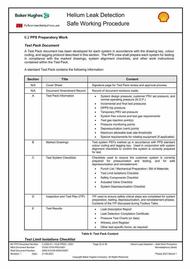
Test Pack Document A Test Pack document has been developed for each system in accordance with the drawing key, colour coding, and tagging protocol described in this section. The PPS crew shall prepare each system for testing in compliance with the marked drawings, system alignment checklists, and other work instructions contained within the Test Pack. A standard Test Pack contains the following information:
Section Title Content
N/A Cover Sheet Signature page for Test Pack review and approval process.
N/A Document Amendment Record Record of document revisions made.
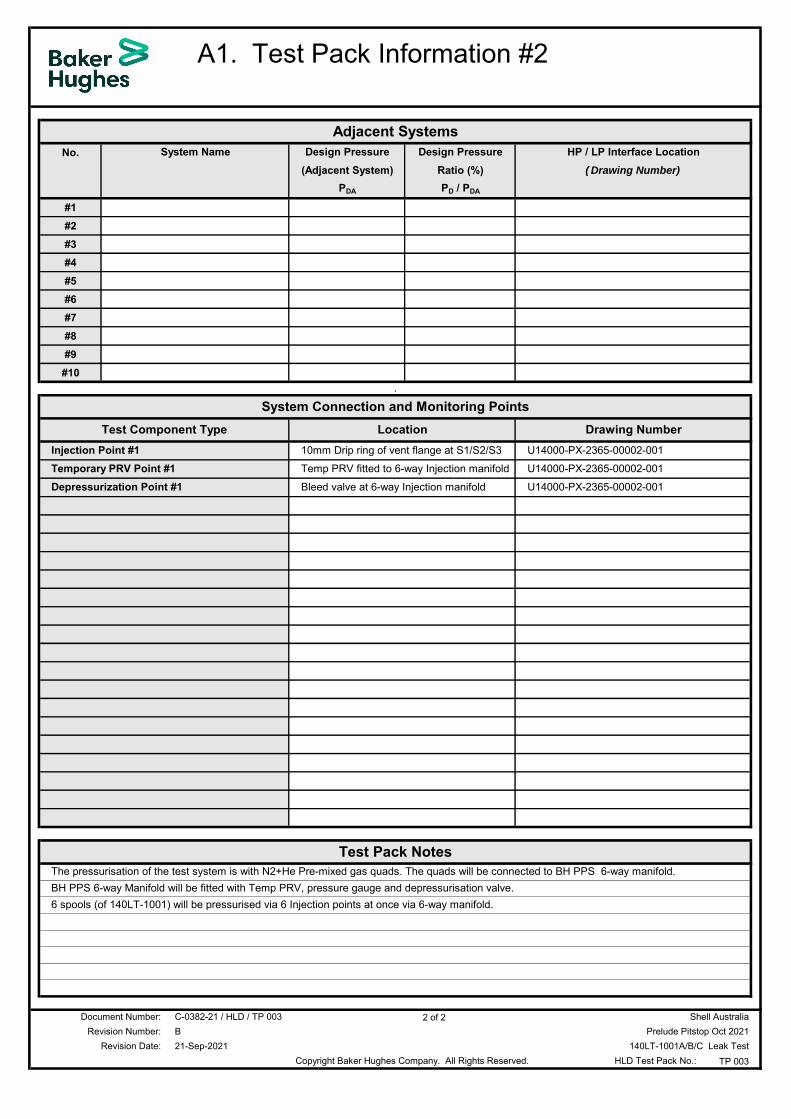
A Test Pack Information • System design pressure, customer PSV set pressure, and normal operating pressure (N.O.P.)
• Incremental and final test pressures
• OPPS trip pressure
• Temporary PRV set pressure
• System free volume and test gas requirements
• Test gas injection point(s)
• Pressure monitoring points
• Depressurization (vent) points
• Maximum allowable leak rate thresholds
• Special requirements for rotating equipment (if applicable)
B Marked Drawings Test system PEFs marked up in accordance with PPS standard colour coding and tagging key. Used in conjunction with system alignment checklists to confirm the system is correctly prepared for test.
C Test System Checklists Checklists used to ensure the customer system is correctly prepared for pressurization and testing, and for safe depressurization and reinstatement.
• Punch List / Mechanical Preparation / Bill of Materials
• Test Limit Isolations Checklist
• Safety Components Checklist
• Actuated Valve Checklist
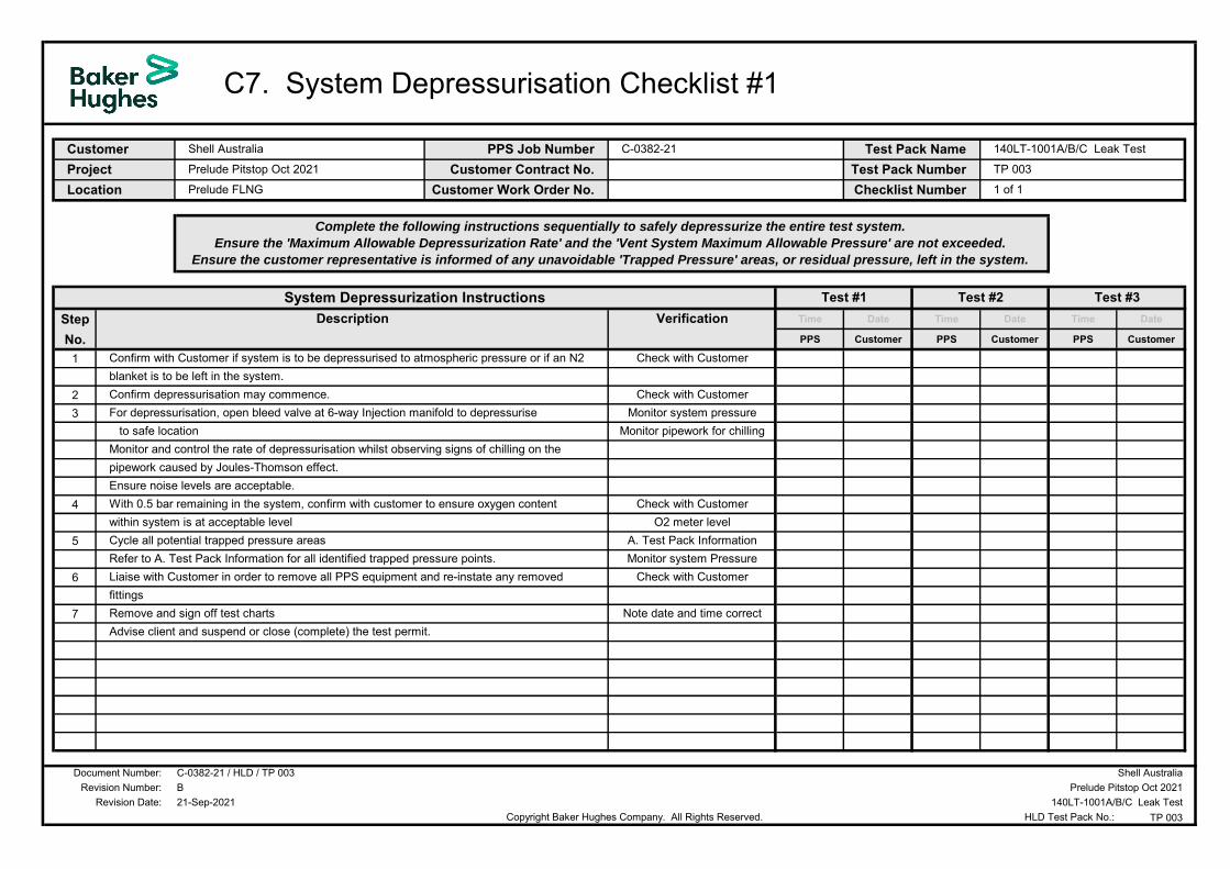
• System Depressurization Checklist
D Inspection and Test Plan (ITP) ITP used to ensure safety critical steps are completed for system preparation, testing, depressurization, and reinstatement phases.
Contents of the ITP discussed during Toolbox Talks.
Copyright Baker Hughes Company. All Rights Reserved.
The PPS Test Limit Isolations Checklist identifies all test system boundaries (limits) that must be positively isolated or in the closed position prior to system pressurization, to safely contain the test gas. All test limit isolations are tagged T# and numbered sequentially. Each test limit component is listed on the checklist and cross referenced on the Test Pack P&IDs (colour coded red).
Safety Components Checklist The PPS Safety Components Checklist identifies any components, either within or outside test boundaries (limits), that have the potential to change position, prevent complete system pressurization, or cause a trapped pressure condition post-depressurization. Each identified safety component must be secured in the open position or checked for correct orientation. All safety components are tagged S# and numbered sequentially. Each component is listed on the checklist and cross referenced on the Test Pack P&IDs (colour coded green). Component types listed include:
• Actuated valves
• Check valves (non-return valves)
• Spectacle blinds and ring spacers
• Maintenance valves upstream or downstream of system PSVs, or temporarily installed PRV
• Customer isolation valves between the main test system and PPS test gas injection manifold, or OPPS pressure sensing manifold
• Critical manual valves on vent paths (double block and bleed) or system depressurization paths
• Components removed to provide direct vent paths to atmosphere (double block and bleed)
In addition to the safety components listed, all manually operated valves within test limit boundaries shall be visually checked prior to system pressurization to ensure in the open position. These valves are (typically) not listed on the checklist.
Actuated Valve Checklist The PPS Actuated Valve Checklist lists all actuated valves associated with the test (and identified on the PPS Test Limit Isolations or PPS Safety Components Checklists). The checklist is issued to the Customer Representative in advance of testing, along with the PPS Punch List, to allow advance preparation of the actuated valves by the customer’s Instrument Technician.
System Depressurization Checklist The PPS System Depressurization Checklist describes the sequential steps taken to ensure the system is completely depressurized after the system has been leak tested. The checklist identifies:
• Depressurization points to be used (location and sequence of each)
• Pressure monitoring points to be checked on the test system and vent path
• Maximum allowable depressurization rate
• Maximum allowable pressure in the vent path system
Checklist Signatories
The above mentioned checklists all require co-signature by the PPS Project Coordinator/ Shift Supervisor and Customer Representative.
Copyright Baker Hughes Company. All Rights Reserved.
Marked PEFs Key, Colour Coding, and Tagging Each Test Pack document contains a set of marked P&IDs defining the test system and cross referencing the system alignment checklists. Information contained within the marked drawings includes:
• Test gas injection manifold installation point(s)
• OPPS pressure sensing point
• Test pressure monitoring points
• Temporary PRV installation point(s)
• Depressurization points
• Vent path pressure monitoring points
• Test system check valve locations
• High pressure / low pressure piping interfaces
• Jumper hoses (if used)
• Trapped pressure sections (piping that cannot be fully depressurized post-test due to plant configuration)
The drawings are marked in accordance with the colour coding and P&ID key shown in Tables 7 and 8.
Copyright Baker Hughes Company. All Rights Reserved.
Over Pressure Protection Each test system is protected against over pressurization using a minimum of two devices:
• PPS Over Pressure Protection System (OPPS)
• Customer PSV
The OPPS takes a pressure signal from the customer system and automatically shuts down the pressurizing pump unit if a pre-set trip pressure is reached. The OPPS pressure sensor shall be installed at a non-isolatable, upstream location close to the test gas injection point (i.e. where the highest pressure is most likely to occur). The OPPS pressure sensing point is clearly identified in each Test Pack.
If a customer PSV is not present or available for a test, or additional over pressure protection is considered necessary, a temporary PRV(s) shall be installed at a non-isolatable, upstream location that provides full system protection. The PRV installation point(s) is clearly identified in each Test Pack. The PRV discharge nozzle shall be orientated to a safe location.
Each PRV provided shall be capable (at the set pressure) of relieving test gas at a flow rate greater than the pressurizing pump’s maximum flow rate capability. For lower pressure tests this approach may result in the requirement for a large diameter PRV. Installing a large diameter PRV may not be practical, and a suitable connection point may not exist. In this situation one of two options shall be implemented:
i. Install multiple smaller PRVs with the same set pressure to cumulatively achieve the required total flow rate. Each PRV shall be clearly numbered and identified in the Test Pack document.
ii. Install a single, smaller PRV at the nominated set pressure and set a maximum allowable pump rate below the PRV flow rate capability. The maximum allowable pump rate shall be recorded in the Test Pack document and communicated during a Toolbox Talk meeting prior to testing operations.
PPS standard practice is to test systems to 90% of the system design pressure or PSV set pressure.
OPPS trip pressure and temporary PRV set pressure are quantified using the rules in Table 9.
At client request system will be tested at working pressure 75 barg
System Design Pressure, PD or PSV Set Pressure
Test Pressure, PT
OPPS Trip Pressure
Temporary PRV Set Pressure
Less than or equal to 5 barg (75 psig) Discussed and agreed with the customer on a test by test basis
Table 9: PPS Standard Rules for Test Pressure, OPPS, and Temporary PRV
For systems with PSV set pressure or design pressure in the range 5 barg (75 psig) or less, the margins between the above mentioned parameters are very small. The test pressure, OPPS trip pressure, and temporary PRV set pressure shall be discussed and agreed during the engineering phase for these tests.
PRV Set Pressure Tolerance ASME BPVC compliant, certified PRVs have an allowable set pressure tolerance of +/-3% under the code rules. These types of PRVs are commonly used in the industry and by the PPS group. Whilst the possibility exists that the PRVs may open at the lower end of their allowable tolerance range (+/-3%), it should not interfere with the test based upon the PPS test pressure rule.
Note: It is mandatory to install a temporary PRV for a system pressurized using an air driven gas booster pump as the OPPS automated trip is not used with this pump type.
Copyright Baker Hughes Company. All Rights Reserved.
Pressure Monitoring
Test Pressure Monitoring
The minimum test pressure monitoring requirement for each test system is:
• 1 x pressure gauge installed directly onto the test system
• 1 x pressure gauge displaying test system pressure at the pressurizing pump location
• 1 x pressure recorder
• Standard customer instrumentation on the test system
Pressure instrumentation may be analog, digital, or a combination of both. All instrumentation shall be calibrated and certified to a recognized industry standard. Analog instrumentation shall have a pressure range that falls within 50% - 90% full scale deflection (FSD) at final test pressure. Analog pressure chart recorder clocks shall be sized to match the anticipated test duration.
The test pressure monitoring instrumentation shall be installed at a non-isolatable, upstream location that provides a full system pressure reading for the pressurization, testing, and depressurization phases. Each test pressure monitoring installation point is clearly identified in the Test Pack document.
Multiple test pressure monitoring points shall be used for test systems containing single direction components such as check valves (non-return valves) to provide pressure indication upstream and downstream (where possible). This enables the test crew to check and ensure the complete system is pressurized for leak testing. The crew can also check and ensure the system is fully depressurized post testing, eliminating potential trapped pressure incidents.
The pressure instrument at the pump location enables the pump operator to continuously monitor the test pressure remotely from the test system, and react immediately to any anomalies that may occur.
Vent Path Pressure Monitoring Upon completion of leak testing each test system is depressurized to atmospheric pressure (or a residual pressure agreed with the customer). The vent path route for depressurization often has a lower pressure rating than the system under test e.g. closed drains or adjacent process system.
The depressurization rate of the test system shall be carefully monitored and controlled to ensure the vent path system is not over pressurized.
Customer system instrumentation permanently installed on the vent path route shall be used to monitor the vent path pressure, if available. If the customer system instrumentation is not available, or if additional pressure monitoring is required, PPS shall install temporary pressure instrumentation onto the vent path for pressure monitoring and recording.
The vent path pressure monitoring points are identified in the Test Pack document and clearly marked on the Test Pack drawings (see Table 8 for notation used)
Copyright Baker Hughes Company. All Rights Reserved.
6.5 Test Exclusion Zone After a system has been prepared for test and is ready for pressurization, barriers shall be placed around the perimeter of the agreed test exclusion zone. Warning signs shall be posted at access points and regular intervals stating:
Figure 1: Warning Sign
The test exclusion zone shall be checked for personnel immediately prior to system pressurization. Any unauthorized personnel shall be escorted outside of the barriers. A site radio announcement shall be made advising that pressurization and testing is due to commence and all barriers and warning signs must be observed.
For Shell Prelude Pitstop 2021 Pressure Testing Warning signage to include Radio Channel to be contacted for more information.
PPS personnel nominated for monitoring the perimeter shall be identified during the Toolbox Talk meeting prior to system pressurization. The test exclusion zone perimeter shall be patrolled at all times when the system is under pressure.
Copyright Baker Hughes Company. All Rights Reserved.
Leak Detection Method Statements This section contains the following standard method statements for leak testing operations:
7.1 Equipment Preparation
7.2 Test System Preparation
7.3 System Pressurization
7.4 Helium Leak Testing
7.5 System Depressurization
Additional Testing
The method statements listed above describe the preparation, pressurization, leak testing, and depressurization activities applied to each test system.
A system shall be prepared, pressurized, and tested again if:
A test is abandoned during the incremental pressure stages due to a gross leak(s) that cannot be safely isolated to allow continuation of pressurization
An initial helium leak test is completed, the system is depressurized, and all identified leaks are repaired
After completing repair work the system shall be prepared for test again, and a helium leak test carried out, as if being pressurized for the first time.
Additional testing shall continue until the system is leak free, or all potential / nominated leak sources have leak rates below the allowable threshold limit. Alternatively, a leak may be accepted by the customer as a witness joint (customer decision).
Copyright Baker Hughes Company. All Rights Reserved.
Equipment Preparation The following activities shall be completed to prepare leak detection equipment for the testing program:
Permit to Work and Toolbox Talk
1. Obtain a current, valid permit for equipment rig up.
2. Hold a Toolbox Talk meeting with the PPS crew to discuss the risks, hazards, and control measures for safe equipment rig up. Invite other personnel affected by the work to attend also.
Position Equipment
3. Position the equipment spread at the designated lay down area:
3.1 Position the nitrogen pump unit and nitrogen tanks into the liquid nitrogen spill bund (berm).
3.2 Position the test cabin and helium gas racks adjacent to the bund area.
3.3 Ensure a charged water hose, spill kits, and fire extinguishers are available.
3.4 Earth all equipment items with spark potential (customer activity, qualified electrician).
3.5 Erect barriers and post warning signs around the circumference of the lay down area.
Utilities
4. Arrange the following utilities (customer supplied) for the nitrogen pump unit, gas booster pump, OPPS, and test cabin:
• Air 7 barg (100 psig), 4 sm3 / min (140 scf / min)
• Water Charged water hose at pump location.
• Electricity 3 Phase 32 Amp min
• Diesel 800 ltr
Inspection
5. Inspect all main equipment items to ensure no damage or loosening occurred during transit. Red tag, quarantine, and repair or replace any equipment items failing inspection.
5.1 Inspect the nitrogen pump unit and verify:
Engine oil filter, hydraulic oil filter, fuel filter, and air filter are in good condition and correctly fitted.
Pressure retaining components are tight.
A check valve is fitted to the pump discharge piping.
A calibrated, certified PRV of the correct set pressure and flow rate capability is fitted on the pump discharge to protect the unit against over pressurization.
An additional PRV of appropriate set pressure and flow rate is fitted to the pump discharge manifold to protect the temporary hose / piping used for gas transfer.
o Not required if the hose / piping is rated at or above the pumps maximum discharge pressure capability.
Note: Only certified rigging personnel are to position equipment.
Under no circumstances shall personnel walk under equipment suspended by a crane or other lifting apparatus.
Copyright Baker Hughes Company. All Rights Reserved.
5.2 Inspect all liquid nitrogen storage tanks to ensure no damage occurred during transit:
Ensure tank PRVs are correctly aligned (not isolated).
Depressurize the tank to condition the liquid nitrogen in readiness for testing.
5.3 Check all helium gas racks for signs of damage. Pay particular attention to the discharge manifold and isolation valves.
5.4 Unload ancillary equipment from the test cabin storage area (e.g. hoses / piping, fittings kit, tool kit, helium gas booster pump, OPPS, etc.).
Take care when opening container doors as items may have moved during transit.
Arrange a crane or other lifting aids for movement of heavy equipment items.
Unavoidable manual lifts of heavy, large, or awkward shaped equipment items to be assessed for correct manual handling techniques. Lifts to be carried out by two (or more) personnel.
5.5 Carry out a visual inspection and certification audit of ancillary equipment items:
Verify the pressure retaining components of the helium gas booster and the OPPS unit are tight (no loosening during transit).
Inspect hoses and hose connectors for signs of damage.
Inspect instrumentation for signs of damage.
Quarantine any damaged items. Arrange replacements (if needed).
Rig Up and Function Test
6. Rig up and function test the equipment spread in preparation for helium leak testing operations:
6.1 Prepare the test cabin:
Ensure the main door and the emergency exit door are unobstructed.
Verify the air supply, power supply, and electrical sockets.
Function test the alarms and trips as per standard practice (if fitted).
Ensure a fire extinguisher is readily available.
Ensure the workspace is clean and tidy. Store any loose items.
6.2 Charge the radio batteries. Function test the radios on the dedicated channel (if available) to ensure working correctly.
6.3 Rig up the helium leak detector and ancillary leak testing equipment in the cabin:
Unpack all items and inspect for signs of damage during transit. Quarantine any damaged items and arrange replacements.
Set up the leak detector and calibration system in accordance with standard practice.
Use a bladder to take a gas sample from the 1% helium / 99% nitrogen gas bottle.
Calibrate the leak detector against the sample and function test to ensure responding correctly to the presence of helium gas.
Copyright Baker Hughes Company. All Rights Reserved.
6.5 Rig up the air driven helium gas booster pump (as per the schematic in Appendix A):
Connect high pressure hosing between;
o Helium gas bottle rack discharge nozzle and the booster pump inlet port.
o Booster pump discharge port and the mixing tee on the nitrogen pump discharge.
Verify the hosing is carefully routed and restraint devices are used.
Connect the air supply and function test the booster pump.
6.6 Carefully route and secure the test gas injection line (hose or iron) from the nitrogen pump discharge to the nominated test gas injection point on the first test system:
Avoid access points.
Verify restraint devices are fitted and the line is secured at regular intervals.
Prepare the test gas injection manifold (check valve and double block and bleed valve configuration). Refer to Appendix C for details.
DO NOT connect the injection line to the customer system at this time.
6.7 Rig up and function test the PPS OPPS in accordance with standard practice:
Verify pressure instrumentation is of appropriate range (50% - 90% FSD at test pressure for analog instruments)
Set the OPPS trip pressure in accordance with the first Test Pack nominated for testing.
Verify the nitrogen pump unit trips at the nominated trip pressure.
6.8 Carefully route and secure the pressure sensing line from the OPPS to the nominated pressure sensing point on the first test system:
Flexible hose for pneumatic OPPS; pressure transducer and cable for electronic OPPS.
Prepare the OPPS pressure sensing point connection manifold (double block and bleed valve configuration). Refer to Appendix A for details.
DO NOT connect the pressure sensing line to the customer system at this time.
6.9 Verify the certification of all equipment used in the rig up:
All components shall be correctly rated for the test pressure and have valid certification.
Any items that are damaged, not certified, or of inadequate pressure rating shall be quarantined and replaced immediately.
Make copies of instrumentation certificates in readiness for the final leak test report.
6.10 Invite the Customer Representative to carry out an equipment inspection and certification audit. Remove and replace any items failing the inspection.
6.11 Cool down, prime, and function test the nitrogen pump unit in accordance with standard practice to ensure working correctly:
Invite the customer representative to witness the function test.
Verify the over pressure switch is correctly set and functioning.
Copyright Baker Hughes Company. All Rights Reserved.
System Preparation
The following activities shall be carried out to prepare each system for pressurization and leak testing:
1. Obtain customer verification that the system is mechanically complete (see Section 6.1) and action items identified on the following PPS forms are closed out:
Punch List
Mechanical Preparation
Actuated Valve Checklist
2. Obtain a current, valid permit to work for system preparation.
3. Line out the test system in accordance with the following Test Pack documents:
Marked P&IDs
Test Limit Isolations Checklist
Safety Components Checklist
4. Seal all potential leak sources with leak detection tape. For Shell Prelude Pitstop 2021 scope of Leak Testing, the compact flanges to be bagged all over including bolts.
5. Visually check and verify the test system preparation (PPS Supervisor and Customer Representative):
Test Limit Isolations
Correct isolation points have been used.
Manual valves are in the fully closed position and rated for full differential pressure.
Actuated valves are in the fully closed position, their energy source is isolated, and they are tight shut off at full differential pressure (test pressure – atmospheric pressure).
Each test limit isolation has a proven vent path to atmosphere (double block and bleed, or single block and bleed) (not applicable for positive isolations such as blind flanges).
PSVs and Burst Discs Devices are fitted as indicated on the P&IDs, and tag set pressure matches the P&ID value.
Maintenance isolation valves for the over pressure device are open, ensuring system protection.
Safety Components
Actuated valves are in the fully open position and their energy source is isolated.
Check valves (non-return valves) are correctly oriented.
Spectacle blinds and spacers are fitted open.
Manual valves within vent paths to atmosphere are in the fully open position
General All other manual valves within test limit boundaries are in the open position.
Instrumentation isolation valves are open (bleed valves closed)
Leak detection tape has been correctly applied to all potential leak sources.
Copyright Baker Hughes Company. All Rights Reserved.
6. Sign off the system alignment checklists and relevant tasks of the Test Pack ITP once satisfied with the equipment rig up and test system alignment (PPS Supervisor and Customer Representative).
Management of change protocol shall be applied if the system cannot be aligned in accordance with the Test Pack P&IDs and system alignment checklists.
System Pressurization The following activities shall be completed to pressurize each system with a nitrogen pump unit:
1. Obtain a current, valid permit to work to pressurize and leak test the system.
2. Verify the ambient temperature and vessel / pipe wall (metal) temperature readings.
3. Hold a Toolbox Talk meeting. Ensure the following items are discussed / reviewed / confirmed:
Maximum allowable pressurization rate and associated pumping rate.
Incremental test pressures and associated hold periods.
Final test pressure.
Test gas requirements.
Leak testing acceptance criteria.
System depressurization procedure and maximum allowable depressurization rate.
Risk assessment review.
Inspection and test plan (ITP) review.
Test exclusion zone perimeter and access points.
Emergency response plan including muster points, responsible persons, and emergency contact numbers.
4. Place barriers and warning signs around the perimeter of the test exclusion zone:
Verify all potential access points to the test area are cordoned off and warning signs posted.
Check the test area. Ensure any unauthorized personnel are escorted outside the test exclusion zone boundaries. The perimeter shall be patrolled by nominated test personnel.
5. Make the final connections to the customer’s system, as detailed in the Test Pack:
5.1. Connect the test gas injection line and manifold from the nitrogen pump discharge.
5.2. Connect the OPPS pressure sensing line and manifold.
5.3. Install the pressure instrumentation (analog, digital, or a combination).
5.4. Fit the temporary PRV(s) (if applicable).
5.5. Verify the final system connections (PPS Supervisor and Customer Representative).
Note: PPS standard operating procedure requires the system metal temperature to be at least 17C (30F) above the MDMT of the pressure vessel or piping (as per ASME BPVC, Section VIII, Division 1, Pneumatic Testing requirement).
Testing may be carried out at a reduced pressure and lower temperature under management of change protocol only if approved by the customer’s technical authority.
Copyright Baker Hughes Company. All Rights Reserved.
6. Arrange for a site radio announcement to be made stating that helium leak testing operations are due to commence, and barriers and warning signs shall be strictly observed.
7. Function test the radio communications. The PPS Pump Operator and Shift Supervisor shall maintain contact at all times during system pressurization.
8. Cool down and prime the nitrogen pump unit (allow 30 minutes for this activity).
9. Pressure test the injection line (hose / piping and manifolds) in accordance with standard practice:
9.1. Pressurize to 90% x hose / piping MAWP (maximum).
9.2. Stop pumping once test pressure is achieved and apply a hold period of 5-minutes.
9.3. Monitor for pressure drop and check for audible leaks:
Depressurize the hose / piping if leaking. Repair or replace the defective component. Re-test.
If the hose / piping is leak tight, function test the pump unit check valve in accordance with standard practice.
10. Subject to a successful pressure test, adjust the test gas injection and OPPS manifold valve positions in readiness for system pressurization.
11. Commence test gas injection (nitrogen and helium):
11.1. Inject test gas at ambient temperature and a low flow rate initially, in accordance with PPS Supervisor instructions. Monitor the system for signs of pressure increase.
If the system pressure begins to rise as expected, gradually increase the test gas injection rate.
Stop pumping if the system pressure does not rise as expected. Identify the problem and rectify.
12. Continue test gas injection until the first incremental pressure level is achieved (2 barg) (30 psig).
12.1. Stop pumping and apply a 10-minute hold period (minimum) to allow system stabilization.
12.2. Verify the pressure increment on the pressure instrumentation and ensure the reading is consistent at all pressure monitoring points. Investigate any discrepancies.
12.3. Take a gas sample from the test system and check the helium concentration using helium leak detector. Adjust helium injection rate accordingly to maintain at 1% by volume concentration.
12.4. Monitor the system pressure for signs of pressure drop.
12.5. Check for audible leaks, passing test limit isolation valves, or gas flow at the bleed points:
If the test system is found to be leaking, or pressure is passing into an adjacent system, shut down the nitrogen pump unit, assess the problem, and inform the Customer Representative.
If a leak source cannot be safely isolated to allow the test to continue, depressurize the system in accordance with the instructions in the PPS System Depressurization Checklist to enable repair work.
Note: The standard pressurization rate is 1 bar / minute (15 psi / minute).
The maximum allowable pressurization rate is 7 bar / minute (100 psi / minute).
Copyright Baker Hughes Company. All Rights Reserved.
If no leaks are detected and system pressure is stable, continue with system pressurization.
13. Re-commence test gas injection and continue until system pressure reaches 25% of final test pressure (second increment). Repeat steps 12.1 to 12.5.
14. Re-commence test gas injection and continue until system pressure reaches 50% of final test pressure (third increment). Repeat steps 12.1 to 12.5.
15. Re-commence test gas injection and continue until system pressure reaches 75% of final test pressure (fourth increment). Repeat steps 12.1 to 12.5.
16. Re-commence test gas injection and continue until the final test pressure (PT) is reached.
17. Stop pumping. Keep the nitrogen pump unit primed.
18. Monitor the test system for pressure drop over a 10-minute period. Ensure all pressure monitoring instrumentation is reading the same value:
If the pressure falls below the final test pressure level due to temperature stabilization of the test gas, top up the system pressure.
If the pressure falls rapidly and continuously, shut down the nitrogen pump unit and investigate the problem.
If the pressure is stable, shut down the nitrogen pump unit.
19. Isolate the test gas injection manifold and helium gas rack. Depressurize the temporary hose / piping.
20. Inform the customer representative that the system is at final test pressure (PT) and helium leak testing operations are due to commence.
Test Pressure Increments and Final Test Pressure
Steps 12 to 16 show the typical increments for pressurizing a customer system. The actual number of increments used, their associated pressures, and the final test pressure is specific to each Test Pack and directly influenced by the system design pressure / PSV set pressure, and the customer’s leak testing philosophy.
Note: Under no circumstances shall repair work be carried out while the piping system or PPS test equipment is under pressure.
Any alterations to valve alignment whilst the system is pressurized shall only be made if collectively agreed between the Customer Representative and PPS Supervisor, and the changes are recorded and approved in compliance with management of change protocol.
Copyright Baker Hughes Company. All Rights Reserved.
Refer to Table 11 for a summary.
System PSV Set Pressure, or Design Pressure, PD
Pressure Increment Test Pressure, PT
First Second Third Fourth
Less than 5 barg (75 psig)
Discussed and agreed with the customer on a test by test basis
5 barg to 20 barg (75 psig to 300 psig)
25% PT 50% PT 75% PT Not Applicable
90% PSV / PD
Greater than 20 barg (300 psig)
2 barg 30 psig
25% PT 50% PT 75% PT 90% PSV / PD
Table 11: Test Pressure Increments and Final Test Pressure
System Pressurization Using Pre-Mixed Gas Racks and an Air Driven Gas Booster
For small volume test systems, requiring less than 200 sm3 (7,000 scf) of gas to achieve test pressure, it is safer and more practical to use pre-mixed 1% helium / 99% nitrogen gas racks and an air driven gas booster for system pressurization. Installation of a temporary PRV is mandatory with this pressurization method.
Copyright Baker Hughes Company. All Rights Reserved.
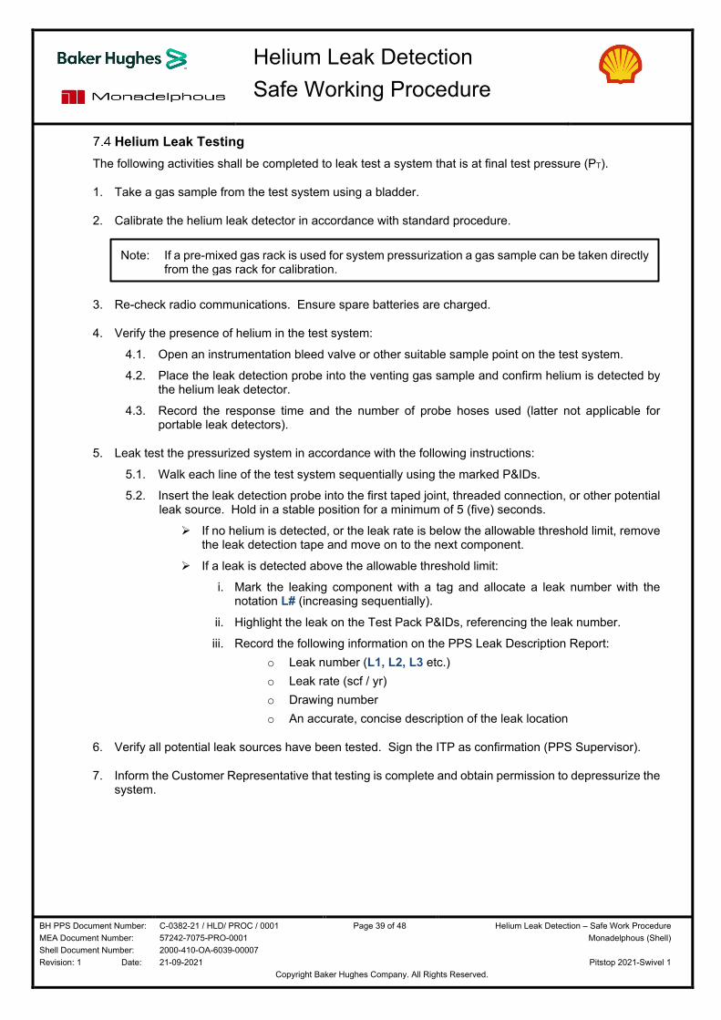
Helium Leak Testing The following activities shall be completed to leak test a system that is at final test pressure (PT).
1. Take a gas sample from the test system using a bladder.
2. Calibrate the helium leak detector in accordance with standard procedure.
3. Re-check radio communications. Ensure spare batteries are charged.
4. Verify the presence of helium in the test system:
4.1. Open an instrumentation bleed valve or other suitable sample point on the test system.
4.2. Place the leak detection probe into the venting gas sample and confirm helium is detected by the helium leak detector.
4.3. Record the response time and the number of probe hoses used (latter not applicable for portable leak detectors).
5. Leak test the pressurized system in accordance with the following instructions:
5.1. Walk each line of the test system sequentially using the marked P&IDs.
5.2. Insert the leak detection probe into the first taped joint, threaded connection, or other potential leak source. Hold in a stable position for a minimum of 5 (five) seconds.
If no helium is detected, or the leak rate is below the allowable threshold limit, remove the leak detection tape and move on to the next component.
If a leak is detected above the allowable threshold limit:
i. Mark the leaking component with a tag and allocate a leak number with the notation L# (increasing sequentially).
ii. Highlight the leak on the Test Pack P&IDs, referencing the leak number.
iii. Record the following information on the PPS Leak Description Report:
o Leak number (L1, L2, L3 etc.)
o Leak rate (scf / yr)
o Drawing number
o An accurate, concise description of the leak location
6. Verify all potential leak sources have been tested. Sign the ITP as confirmation (PPS Supervisor).
7. Inform the Customer Representative that testing is complete and obtain permission to depressurize the system.
Note: If a pre-mixed gas rack is used for system pressurization a gas sample can be taken directly from the gas rack for calibration.
Copyright Baker Hughes Company. All Rights Reserved.
System Depressurization The method statement below describes the activities to be completed for safe depressurization of each test system following completion of the leak testing process.
1. Verify the test system is correctly aligned for depressurization (PPS Supervisor and Customer Representative):
If system alignment was modified under management of change protocol, the system alignment shall be reinstated to the originally approved position prior to commencing depressurization.
If an approved change resulted in a revised or new system alignment and PPS System Depressurization Checklist, the new instructions shall be strictly followed.
2. Depressurize the entire test system to atmospheric pressure in compliance with the PPS System Depressurization Checklist:
Complete each sequential step on the checklist and sign as verification (PPS Supervisor and Customer Representative).
Ensure the initial stage of depressurization is slow by only opening the vent valve a fraction.
Monitor the vent path pressure instrumentation to ensure the maximum allowable vent system pressure is not exceeded. This takes precedence over all other parameters, including system depressurization rate.
Monitor the test system pressure continuously, adjusting the depressurization valve(s) position to maintain the depressurization rate at (or below) the agreed value. Ensure the maximum allowable depressurization rate is not exceeded.
Monitor the system piping temperature adjacent to each depressurization point to ensure excessive chilling does not occur caused by the Joule – Thomson effect. Visual warning signs are condensation on the pipe outer wall. Decrease the depressurization rate if required.
3. Check all pressure monitoring instrumentation to verify the entire system is depressurized to atmospheric pressure. Pay particular attention to pressure monitoring points upstream and downstream of single direction components such as check valves (non-return).
If repair work is to be carried out, all valves within the adjacent area shall be cycled to ensure there is no trapped pressure in the valve cavity.
4. Verify the pressure test data has been accurately recorded.
5. Ensure all leak detection tape has been removed from the system. Remove barriers and warning signs.
6. Sign off the permit, noting that the system is at atmospheric pressure (or, record the residual pressure if left under an inert blanket at the request of the Customer Representative).
Note: The standard depressurization rate is 2 bar / minute (30 psi / minute).
The maximum allowable depressurization rate is 7 bar / minute (100 psi / minute).
Regulating the depressurization rate using a valve is not required if depressurizing through a permanent restriction orifice into a flare system, vent header, or other system designed for gas service (the orifice is the regulating device).
Note: The Customer may request that residual pressure is left in the system. The vent valves (depressurization points) shall be closed when the residual pressure is reached.
The customer may also request that test gas is decanted to another system upon completion of the test. In order to ensure safe transfer of gas the receiving system shall be fully prepared and aligned for test in accordance with the instructions in Section 6.2.
Copyright Baker Hughes Company. All Rights Reserved.
Project Paperwork In addition to the marked Test Pack P&IDs and signed checklists, the paperwork listed in Table 12 shall be generated and placed in Section E of each Test Pack document upon successful completion of testing.
Test paperwork requires review and acceptance (signature) by the Customer Representative.
Test Pack Paperwork Distribution PPS Customer
Leak Description Report Original Copy
Leak Detection Completion Certificate Original Copy
Pressure Test Charts Original Copy
Witness Joint Register Original Copy
Nitrogen Gas Log Original Copy
Table 12: Test Pack Paperwork
The project management paperwork listed in Table 13 shall be maintained throughout the project and presented to the Customer Representative for review and acceptance (signature). Frequency for submission of the paperwork shall be discussed and agreed with the Customer Representative, and comply with contractual requirements.
Project Management Paperwork Distribution PPS Customer
Personnel Timesheets Original Copy
Equipment Schedules Original Copy
Materials and Services Original Copy
Daily Operations Report Original Copy
Monthly Charges Original Copy
Consumables Sheet Original Copy
Job Site Customer Satisfaction Survey Original Copy
Copyright Baker Hughes Company. All Rights Reserved.
Resources The following personnel, equipment, and material resources are the minimum required to complete the scope of work described in Section 3 of this document. Customer supplied items are also summarized.
Any additional resources required to support the project will be discussed and agreed with the customer under the terms of the contract, or management of change protocol.
PPS Personnel Personnel shown in Figure 2 shall be mobilized to provide 24-hr working (back-to-back 12-hour shifts).
Figure 2: PPS Personnel Crew Structure
PPS Equipment PPS shall mobilize the equipment items shown in Table 14 to the project site. Appendix A contains a standard equipment rig up drawing showing how each item is used to support the leak testing scope of work.
Copyright Baker Hughes Company. All Rights Reserved.
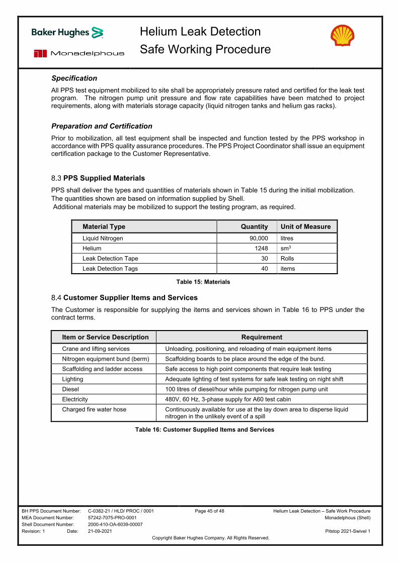
Specification All PPS test equipment mobilized to site shall be appropriately pressure rated and certified for the leak test program. The nitrogen pump unit pressure and flow rate capabilities have been matched to project requirements, along with materials storage capacity (liquid nitrogen tanks and helium gas racks).
Preparation and Certification Prior to mobilization, all test equipment shall be inspected and function tested by the PPS workshop in accordance with PPS quality assurance procedures. The PPS Project Coordinator shall issue an equipment certification package to the Customer Representative.
PPS Supplied Materials PPS shall deliver the types and quantities of materials shown in Table 15 during the initial mobilization.
The quantities shown are based on information supplied by Shell.
Additional materials may be mobilized to support the testing program, as required.
Material Type Quantity Unit of Measure Liquid Nitrogen 90,000 litres
Helium 1248 sm3
Leak Detection Tape 30 Rolls
Leak Detection Tags 40 items
Table 15: Materials
Customer Supplier Items and Services The Customer is responsible for supplying the items and services shown in Table 16 to PPS under the contract terms.
Item or Service Description Requirement Crane and lifting services Unloading, positioning, and reloading of main equipment items
Nitrogen equipment bund (berm) Scaffolding boards to be place around the edge of the bund.
Scaffolding and ladder access Safe access to high point components that require leak testing
Lighting Adequate lighting of test systems for safe leak testing on night shift
Diesel 100 litres of diesel/hour while pumping for nitrogen pump unit
Electricity 480V, 60 Hz, 3-phase supply for A60 test cabin
Charged fire water hose Continuously available for use at the lay down area to disperse liquid nitrogen in the unlikely event of a spill
BHC supervisor and customer representative check each
test limit isolation valve type during system alignment and
verify they are capable of tight shut off when pressurized.
Double block and bleed isolations applied where possible.
Equipment preparation
Trained, competent personnel set the OPPS trip pressure
and carry out the function test.
Gas bottle pressure regulator used for controlling the
OPPS calibration pressure.
OPPS function test witnessed and verified by the BHC
supervisor and customer representative. Test pack ITP
signed as confirmation.
Final test pressure less than the OPPS trip pressure.
Customer PSV on line and / or temporary PRV installed
onto test system as secondary over pressure protection,
and set pressure verified.
Equipment function test
Tape kept in the test cabin or warm environment prior to
use - brittle when cold. Gloves worn.
Care taken, particularly when applying tape in close
proximity to sharp edges.
H d / t i di ti f th b d
Test System Preparation
Instrumentation inspected, pressure rating verified, and
certification checked by BHC supervisor and customer
representative. Test pack ITP signed as confirmation.
Leak test hold period applied at incremental and final test
pressures, and checks made for audible leaks, prior to
personnel entering the test area.
PRV visually inspected, set pressure verified, and
certification checked by the BHC supervisor and customer
representative. Test pack ITP signed as confirmation.
OPPS is primary over pressure protection device, with
PRV mechanical back up.
All test equipment installation points verified against the
test pack drawings and system alignment checklist by the
BHC supervisor and customer representative prior to
testing. Test pack ITP signed as confirmation.
Management of Change protocol applied to:
i. Identify a new adequately sized connection point that
provides full system coverage.
ii. Or, install the PRV at the originally designated
connection point, calculate the reduced flow rate capability
at the set pressure, and restrict the test gas injection below
this value. Record the pump rate restriction in the test
pack and discuss during the toolbox talk meeting prior to
testing.
BHC supervisor and customer representative verify the test
system is correctly aligned against marked P&IDs and the
Test Limit Isolations Checklist (signed as confirmation).
BHC supervisor and customer representative check each
test limit isolation and verify they are adequately rated for
the nominated test pressure.
Process and Pipeline Services
NOTE: Additional information and guidance on Service Delivery impacts can be viewed in the Reliability Assurance
CONTROLS / BARRIERS including OPERATIONAL PROCEDURES / CONTINGENCIES
What are the CONTROLS / BARRIERS, to Control, Mitigate, Eliminate, or Prevent the identified THREAT / HAZARD / ASPECT?NOTE: Barriers can be Equipment, Process, or People
All Threats, Hazards, and Aspects are evaluated using the Five Fundamentals methodology to ensure each identified risk is appropriately mitigated.It is everyone's responsibility to "STOP WORK" when Unsafe Conditions or Conditions that do not support product quality or delivery are recognized.
NOTE: Risk Levels identified as "RL1" REQUIRE "STOP WORK" until controls are in place to reduce risk or impact.For "RL2" Risk Levels, if controls cannot be implemented the team must stop and revaluate task to determine new controls that can be implemented.
Each Threat, Hazard, and Aspect has been classified with a Risk Level. There are two Risk Level classifications (RL1 and RL2) and they are defined as:RL1 – Immediately Dangerous to Life or Health (IDLH), Life Critical, major environmental impact, Process Safety, serious injury, explosion, dropped objects, loss of well control, loss of primary containment, major property damage greater than $250,000, or a PL Reliability and Service Delivery incident classified as High Impact. RL2 – All remaining HSE not listed in RL1 and Service Delivery impacts classified as a Low or Medium Impact.
Incident Impact Definition procedure.
Leak Detection
Hard Hat, Safety Glasses/Goggles/Face Shield, Flame Retardant Coveralls, Gloves, Safety Boots
Field Operations
PPS Site Safety, PPS Nitrogen Pumping
Uncontrolled when printed. Confirm the correct revision is used.
Activity / Service Type:Related ORAs:Required PPE:
(Personal Protective Equipment)Location:
TASK /PROCESS STEP
THREATS / HAZARDS / ASPECTS
How can the TASK, STEP, or CHANGE go wrong?What are the potential Consequences?
What are the Gaps?
Uncontrolled RISK LEVEL
Controlled RISK LEVEL
Process and Pipeline Services
NOTE: Additional information and guidance on Service Delivery impacts can be viewed in the Reliability Assurance
CONTROLS / BARRIERS including OPERATIONAL PROCEDURES / CONTINGENCIES
What are the CONTROLS / BARRIERS, to Control, Mitigate, Eliminate, or Prevent the identified THREAT / HAZARD / ASPECT?NOTE: Barriers can be Equipment, Process, or People
All Threats, Hazards, and Aspects are evaluated using the Five Fundamentals methodology to ensure each identified risk is appropriately mitigated.It is everyone's responsibility to "STOP WORK" when Unsafe Conditions or Conditions that do not support product quality or delivery are recognized.
NOTE: Risk Levels identified as "RL1" REQUIRE "STOP WORK" until controls are in place to reduce risk or impact.For "RL2" Risk Levels, if controls cannot be implemented the team must stop and revaluate task to determine new controls that can be implemented.
Each Threat, Hazard, and Aspect has been classified with a Risk Level. There are two Risk Level classifications (RL1 and RL2) and they are defined as:RL1 – Immediately Dangerous to Life or Health (IDLH), Life Critical, major environmental impact, Process Safety, serious injury, explosion, dropped objects, loss of well control, loss of primary containment, major property damage greater than $250,000, or a PL Reliability and Service Delivery incident classified as High Impact. RL2 – All remaining HSE not listed in RL1 and Service Delivery impacts classified as a Low or Medium Impact.
Incident Impact Definition procedure.
Leak Detection
Hard Hat, Safety Glasses/Goggles/Face Shield, Flame Retardant Coveralls, Gloves, Safety Boots
Field Operations
PPS Site Safety, PPS Nitrogen Pumping
Manual valve or actuated valve closed
within test limit boundaries, causing:
- isolation of OPPS and / or PRV
- isolation of test instrumentation
- future leaks from untested joints
- trapped pressure post testing
RL1 HSE RL2 HSE
Check valve (non return valve)
incorrectly orientated, or spectacle blind
fitted closed, within test limit boundaries
causing:
- future leaks from untested joints
- trapped pressure post testing
RL1 HSE RL2 HSE
Site conditions require change to:
- test limit isolations
- test gas injection point
- depressurization point
- pressure monitoring point
- OPPS pressure sensing point
- temporary PRV installation point
Potential for:
- pressurization of adjacent system
- untested components
- trapped pressure
- damage to rotating equipment
RL1 HSE RL2 HSE
Test exclusion zone
Access routes left open allowing
unauthorized personnel to enter the test
area and interfere with the test system. RL1 HSE RL2 HSE
Calibration issue with customer PSV /
burst disc / temporary PRV causes an
unexpected gas discharge below the set
pressure. RL2 HSE RL2 HSE
Actuated valve used for test limit
isolation changes position during the test
from closed to open, causing an
uncontrolled:
- pressure release to atmosphere
- adjacent system over-pressurized
RL1 HSE RL2 HSE
Test limit isolation passing causing
uncontrolled pressurization / over
pressurization of the adjacent system. RL1 HSE RL2 HSE
Customer system component failure
below nominated test pressure due to
incorrectly specified or defective
material, excessive erosion, corrosion,
defective welds, incorrect joint make-up,
or other cause, resulting in:
- uncontrolled gas release
- personnel injury
- equipment damage
RL1 HSE RL2 HSE
Test System Preparation
Proposed changes to the approved test pack are risk
assessed and recorded in compliance with Management of
Change protocol.
Approvals are obtained from authorized BHC and customer
representatives prior to implementation, if safe to proceed.
BHC supervisor verifies barriers and warning signs are
correctly positioned around the entire test exclusion zone.
Unauthorized personnel removed. Test exclusion zone
perimeter patrolled throughout the test. Test pack ITP
signed as verification.
BHC supervisor and customer representative check each
manual and actuated valve within test limits and verify in
the open position. Actuated valves within test limits have
their motive power source isolated (electricity / air /
hydraulic) by the customer instrument technician to ensure
the valve remains open and cannot be operated remotely.
Safety Components Checklist signed as confirmation.
BHC supervisor and customer representative visually
inspect each check valve and spectacle blind within test
limit boundaries for correct orientation.
Safety Components Checklist signed as confirmation.
Safety device tag data and set pressure verified by the
BHC supervisor and customer representative during
system preparation. Temporary PRV discharge orientated
in a safe direction, away from a walkway, access point, or
common area. If safety device lifts below set pressure, the
customer representative shall be notified immediately and
testing will stop pending investigation.
Test limit isolations used are blinds, spades, closed
spectacle blinds, and single or double block and bleed
valve isolations that protect the adjacent systems.
Bleed valves are checked and pressure is monitored in
adjacent systems during the test.
Customer representative confirms the test system is
mechanically complete, MDMT verified, and all system
components have successfully passed NDT / hydrostatic
test / pneumatic strength test / FAT in compliance with
code requirements. Test pack ITP signed as verification.
Customer to carry out wall thickness checks prior to testing
if any uncertainty about the system condition.
System pressurized in increments and checks made for
audible leaks during hold periods, prior to personnel
entering the test area.
All actuated valves used for test limits have their motive
power source isolated (electricity / air / hydraulic) by the
customer instrument technician to ensure the valve
remains closed and cannot be operated remotely.
BHC supervisor and customer representative visually
check each actuated valve is correctly isolated in the
closed position. Test Limit Isolations Checklist signed as
ifi ti i t i ti
System pressurization
Uncontrolled when printed. Confirm the correct revision is used.
Activity / Service Type:Related ORAs:Required PPE:
(Personal Protective Equipment)Location:
TASK /PROCESS STEP
THREATS / HAZARDS / ASPECTS
How can the TASK, STEP, or CHANGE go wrong?What are the potential Consequences?
What are the Gaps?
Uncontrolled RISK LEVEL
Controlled RISK LEVEL
Process and Pipeline Services
NOTE: Additional information and guidance on Service Delivery impacts can be viewed in the Reliability Assurance
CONTROLS / BARRIERS including OPERATIONAL PROCEDURES / CONTINGENCIES
What are the CONTROLS / BARRIERS, to Control, Mitigate, Eliminate, or Prevent the identified THREAT / HAZARD / ASPECT?NOTE: Barriers can be Equipment, Process, or People
All Threats, Hazards, and Aspects are evaluated using the Five Fundamentals methodology to ensure each identified risk is appropriately mitigated.It is everyone's responsibility to "STOP WORK" when Unsafe Conditions or Conditions that do not support product quality or delivery are recognized.
NOTE: Risk Levels identified as "RL1" REQUIRE "STOP WORK" until controls are in place to reduce risk or impact.For "RL2" Risk Levels, if controls cannot be implemented the team must stop and revaluate task to determine new controls that can be implemented.
Each Threat, Hazard, and Aspect has been classified with a Risk Level. There are two Risk Level classifications (RL1 and RL2) and they are defined as:RL1 – Immediately Dangerous to Life or Health (IDLH), Life Critical, major environmental impact, Process Safety, serious injury, explosion, dropped objects, loss of well control, loss of primary containment, major property damage greater than $250,000, or a PL Reliability and Service Delivery incident classified as High Impact. RL2 – All remaining HSE not listed in RL1 and Service Delivery impacts classified as a Low or Medium Impact.
Incident Impact Definition procedure.
Leak Detection
Hard Hat, Safety Glasses/Goggles/Face Shield, Flame Retardant Coveralls, Gloves, Safety Boots
Field Operations
PPS Site Safety, PPS Nitrogen Pumping
Damaged / crushed / incorrectly rated
gasket fails under pressure, resulting in:
- uncontrolled gas release
- flying debris
- personnel injury RL1 HSE RL2 HSE
Loose plug / damaged threads on
system component causes failure under
pressure, resulting in:
- uncontrolled gas release
- flying projectile
- personnel injury
RL1 HSE RL2 HSE
Leaking components generate high
noise level, resulting in personnel
hearing damage.
Potential causes of leaks include:
- misaligned pipe
- scored / corroded flange face
- missing gasket
- missing bolts or loose bolts
- incorrect torque / tension settings
- valve stem leaks
- missing plug, instrument, etc.
RL1 HSE RL2 HSE
Leaking test gas creates an asphyxiation
hazard in an enclosed area.
RL1 HSE RL2 HSE
System pressurization
Inclement weather conditions (such as
heavy rain, thunderstorms, high wind
speed, heavy snow, ice, extreme cold
temperatures, extreme high
temperatures) create dangerous working
conditions causing personnel injury or
plant damage.
RL1 HSE RL2 HSE
Unauthorized personnel enter the test
area and interfere with the test system,
causing an uncontrolled pressure
release, plant damage, or personnel
injury.
RL1 HSE RL2 HSE
Joints / potential leak sources missed
during the leak test, resulting in a
hydrocarbon release during start up. RL1 HSE RL2 HSE
Customer representative requests a
leaking joint is isolated (system
alignment is changed) to enable
continuation and completion of testing.
Failure to realign the system upon
completion of testing causes a trapped
pressure event post depressurization.
RL1 HSE RL2 HSE
BHC supervisor and customer representative shall monitor
the weather conditions in advance of test and determine
whether safe for personnel to work.
If ambient temperature is anticipated to fall within 17C
(30F) of the vessel MDMT or the piping ductile - brittle
transition temperature, the test shall be postponed until
ambient temperature increases (Ref: ASME BPV).
BHC supervisor and customer representative assess the
severity of a leak and determine whether safe to isolate
and proceed with testing, or if a test shall be stopped.
Proposed changes to the approved test pack are risk
assessed and recorded in compliance with Management of
Change protocol.
Approvals are obtained from authorized BHC and customer
representatives prior to implementation, if safe to proceed.
Leak testing
Permit to work system in effect to prevent work activities
conflicts (SIMOPS).
Barriers erected, warning signs posted. Radio
announcement made.
Test exclusion zone patrolled whilst system is being
pressurized, leak tested, and depressurized.
BHC supervisor checks the system against marked P&IDs
following completion of the leak test to verify all potential
leak sources have been tested.
The test pack ITP is signed as confirmation.
Threaded connections checked to verify components are
correctly fitted prior to testing (customer responsibility).
Test Pack ITP signed by customer representative as
verification. System pressurized in increments and checks
made for audible leaks during hold periods, prior to
personnel entering the test area.
Pipe alignment tolerances verified and flange faces visually
inspected during bolted flange joint make up. BHC
supervisor and customer representative visually check the
system during system preparation and verify all
components are fitted prior to testing. Bolted flange joints
are checked to ensure nuts / bolts / gaskets are fitted, and
torque / tension tags are in place. Test Pack ITP signed by
customer representative as verification.
System pressurized in increments and checks made for
audible leaks during hold periods prior to personnel
entering the test area.
Personnel issued with hearing protection.
Test area assessed by BHC supervisor and customer
representative prior to pressurization. Enclosed area
safety controls discussed during toolbox talk.
Personal oxygen meters used. Standalone gas monitors
with audible visual alarms placed in enclosed areas.
Personnel in continuous radio contact. "Buddy" system
applied - minimum 2 x BHC personnel.
Bolted flange joints made up by qualified, competent
personnel. Correct gasket selected and visually checked
for damage prior to installation. Correct torque / tension
applied in compliance with industry standard. Joint make
up verified by flange management system. Pressurization
in increments and checks made for audible leaks during
hold periods prior to personnel entering the test area.
Personnel instructed not to stand in the line of fire when
testing flanged joints.
System pressurization
Uncontrolled when printed. Confirm the correct revision is used.
Activity / Service Type:Related ORAs:Required PPE:
(Personal Protective Equipment)Location:
TASK /PROCESS STEP
THREATS / HAZARDS / ASPECTS
How can the TASK, STEP, or CHANGE go wrong?What are the potential Consequences?
What are the Gaps?
Uncontrolled RISK LEVEL
Controlled RISK LEVEL
Process and Pipeline Services
NOTE: Additional information and guidance on Service Delivery impacts can be viewed in the Reliability Assurance
CONTROLS / BARRIERS including OPERATIONAL PROCEDURES / CONTINGENCIES
What are the CONTROLS / BARRIERS, to Control, Mitigate, Eliminate, or Prevent the identified THREAT / HAZARD / ASPECT?NOTE: Barriers can be Equipment, Process, or People
All Threats, Hazards, and Aspects are evaluated using the Five Fundamentals methodology to ensure each identified risk is appropriately mitigated.It is everyone's responsibility to "STOP WORK" when Unsafe Conditions or Conditions that do not support product quality or delivery are recognized.
NOTE: Risk Levels identified as "RL1" REQUIRE "STOP WORK" until controls are in place to reduce risk or impact.For "RL2" Risk Levels, if controls cannot be implemented the team must stop and revaluate task to determine new controls that can be implemented.
Each Threat, Hazard, and Aspect has been classified with a Risk Level. There are two Risk Level classifications (RL1 and RL2) and they are defined as:RL1 – Immediately Dangerous to Life or Health (IDLH), Life Critical, major environmental impact, Process Safety, serious injury, explosion, dropped objects, loss of well control, loss of primary containment, major property damage greater than $250,000, or a PL Reliability and Service Delivery incident classified as High Impact. RL2 – All remaining HSE not listed in RL1 and Service Delivery impacts classified as a Low or Medium Impact.
Incident Impact Definition procedure.
Leak Detection
Hard Hat, Safety Glasses/Goggles/Face Shield, Flame Retardant Coveralls, Gloves, Safety Boots
Field Operations
PPS Site Safety, PPS Nitrogen Pumping
Test gas vented locally into an enclosed
space creating an asphyxiation hazard.
RL1 HSE RL2 HSE
Incorrect depressurization point used
resulting in trapped pressure
downstream of a system check valve
(non return valve). RL1 HSE RL2 HSE
Manual valve closed within test limit
boundaries resulting in trapped
pressure. RL1 HSE RL2 HSE
Incorrect depressurization point used
resulting in over pressurization of the
adjacent system. RL1 HSE RL2 HSE
Incorrect depressurization point used
resulting in accidental rotation and
damage to mechanical equipment.
RL1 HSE RL2 HSE
High depressurization rate (in excess of
agreed maximum rate) causes over
pressurization of piping and customer
equipment on the approved vent path.
RL1 HSE RL2 HSE
Excessive depressurization rate causes
chilling of piping due to Joule - Thomson
effect ( gas expansion), resulting in the
ductile - brittle transition temperature
exceeded.
RL1 HSE RL2 HSE
Excessive noise level exceeds
acceptable local HSE limits, or causes
personnel hearing damage RL1 HSE RL2 HSE
Pressure left in system at the customer's
request. Uncontrolled pressure release
and personnel injury when third party
personnel work on the system after test.RL1 HSE RL2 HSE
Piping at depressurization points closely monitored for
signs of chilling (condensation, frosting). Depressurization
rate reduced by BHC supervisor.
See additional controls above for excessive
depressurization rate.
System depressurization
System depressurization points are clearly identified in the
test pack (marked P&IDs, System Depressurization
Checklist). Only approved depressurization points are
used. Vent paths are checked by the BHC supervisor in
advance of testing to ensure test gas does not route into
an enclosed space. Flares and vent headers are used for
system depressurization wherever possible.
Temporary, secured hose used to route test gas from a
local vent point to a safe location if flare or vent header
unavailable.
Personnel oxygen meters used.
Depressurization carried out in accordance with the
System Depressurization Checklist, verified and signed off
by BHC supervisor and customer representative.
Pressure monitoring points checked upstream and
downstream of check valves to ensure the system is fully
depressurized.
BHC supervisor and customer representative verify each
manual valve within test limit boundaries is open.
Management of Change documents reviewed to ensure
any system alignment changes are identified and rectified.
Depressurization carried out in accordance with System
Depressurization Checklist and ITP, signed off by BHC
supervisor and customer representative. Adjacent
systems monitored for signs of pressure increase.
System depressurization
Depressurization rate controlled to minimize the noise level
generated in compliance with local HSE requirements.
Gas routed to the flare / vent header where possible.
Hearing protection worn by personnel.
Residual pressure level verified by the BHC supervisor and
customer representative, and recorded on the System
Depressurization Checklist, test pack ITP, and the test
permit. Customer permit office advised of system status.
Customer technical authority and OEM vendor
representative consulted regarding depressurization of
systems containing rotating mechanical equipment during
the engineering phase.
Depressurization points and maximum allowable
depressurization rates recorded in the test pack, and
discussed at a toolbox talk meeting prior to test.
Depressurization carried out in accordance with the
System Depressurization Checklist, verified and signed by
the BHC supervisor and customer representative.
Maximum allowable depressurization rate and vent path
pressure are recorded in the test pack document, and
discussed at toolbox talk meeting. Flare and vent headers,
if used, are (typically) designed for handling process flow
rates well in excess of those generated during system
depressurization. Vent path pressure instrumentation is
continuously monitored during the depressurization activity
to ensure maximum allowable vent path pressure is not
exceeded.
Uncontrolled when printed. Confirm the correct revision is used.
Activity / Service Type:Related ORAs:Required PPE:
(Personal Protective Equipment)Location:
TASK /PROCESS STEP
THREATS / HAZARDS / ASPECTS
How can the TASK, STEP, or CHANGE go wrong?What are the potential Consequences?
What are the Gaps?
Uncontrolled RISK LEVEL
Controlled RISK LEVEL
Process and Pipeline Services
NOTE: Additional information and guidance on Service Delivery impacts can be viewed in the Reliability Assurance
CONTROLS / BARRIERS including OPERATIONAL PROCEDURES / CONTINGENCIES
What are the CONTROLS / BARRIERS, to Control, Mitigate, Eliminate, or Prevent the identified THREAT / HAZARD / ASPECT?NOTE: Barriers can be Equipment, Process, or People
All Threats, Hazards, and Aspects are evaluated using the Five Fundamentals methodology to ensure each identified risk is appropriately mitigated.It is everyone's responsibility to "STOP WORK" when Unsafe Conditions or Conditions that do not support product quality or delivery are recognized.
NOTE: Risk Levels identified as "RL1" REQUIRE "STOP WORK" until controls are in place to reduce risk or impact.For "RL2" Risk Levels, if controls cannot be implemented the team must stop and revaluate task to determine new controls that can be implemented.
Each Threat, Hazard, and Aspect has been classified with a Risk Level. There are two Risk Level classifications (RL1 and RL2) and they are defined as:RL1 – Immediately Dangerous to Life or Health (IDLH), Life Critical, major environmental impact, Process Safety, serious injury, explosion, dropped objects, loss of well control, loss of primary containment, major property damage greater than $250,000, or a PL Reliability and Service Delivery incident classified as High Impact. RL2 – All remaining HSE not listed in RL1 and Service Delivery impacts classified as a Low or Medium Impact.
Incident Impact Definition procedure.
Leak Detection
Hard Hat, Safety Glasses/Goggles/Face Shield, Flame Retardant Coveralls, Gloves, Safety Boots
Field Operations
PPS Site Safety, PPS Nitrogen Pumping
Leak detection tape left on the system
after final test, creating a corrosion
hazard.RL2 HSE RL2 HSE
Customer unable to start up the plant
due to test blinds / spades / closed
spectacle blinds left in test system.RL2 HSE RL2 HSE
Hydrocarbon release during start up due
to test equipment connection points and
system depressurization points being left
open directly to atmosphere upon
completion of testing.
RL1 HSE RL2 HSE
System reinstatement
Test system checked by BHC supervisor post
depressurization to verify all leak detection tape has been
removed. The test pack ITP is signed as confirmation.
Witness Joint Register and Mechanical Reinstatement
checklists issued to the customer representative after
completing testing, identifying items to be reinstated.
Witness Joint Register and Mechanical Reinstatement
checklists issued to the customer representative after
completing testing, identifying items to be reinstated.
Uncontrolled when printed. Confirm the correct revision is used.
Activity / Service Type:Related ORAs:Required PPE:
(Personal Protective Equipment)Location:
TASK /PROCESS STEP
THREATS / HAZARDS / ASPECTS
How can the TASK, STEP, or CHANGE go wrong?What are the potential Consequences?
What are the Gaps?
Uncontrolled RISK LEVEL
Controlled RISK LEVEL
Personnel struck by falling objects, or
trapped underneath equipment.
RL1 HSE RL2 HSE
Large, heavy object dropped on
pressurized equipment causing:
- component failure and flying debris
- uncontrolled gas release
- personnel injury
RL1 HSE RL2 HSE
Failure of lifting device (pad-eyes, slings
/ chains, rigging equipment, hydraulic
loading equipment e.g. Hiab) causes
personnel injury and equipment damage.RL1 HSE RL2 HSE
Equipment hits and damages the
customer's plant whilst being moved into
position. RL1 HSE RL2 HSE
Spill control bund (berm) construction
Personnel injuries during construction of
the spill control bund (berm), caused by:
- trapped fingers
- slip on wet surface
- trip on uneven tarpaulin / raised side
RL2 HSE RL2 HSE
Personnel injury caused by:
- container door handle springs up
- container door swings open
- equipment falling out of storageRL2 HSE RL2 HSE
Incorrect lifting technique whilst carrying
out manual handling of large, heavy, or
awkward shaped equipment causes
personnel injury.RL2 HSE RL2 HSE
Electricity supply to equipment
incorrectly rigged up creating an
electrocution hazard.RL1 HSE RL2 HSE
Defective air hose or incorrect couplings,
results in an uncontrolled pressure
release, whipping hose, flying debris,
and personnel injury.
RL2 HSE RL2 HSE
Fuel transfer
Fuel spill during fuel tank filling operation
creates flammable hazard, and potential
fire if ignition source is present.
RL1 HSE RL2 HSE
Incorrect selection and use of hand
tools, or defective tools, cause personnel
injury and / or damage to BHC
equipment.
RL2 HSE RL2 HSE
Poor routing of hoses / iron / piping
creates trip hazard, causing personnel
injury. RL2 HSE RL2 HSE
Lifts carried out by qualified, competent third party
personnel with certified lifting equipment in compliance with
an approved lift plan (assessment of load, lift point, arc of
lift, trajectory, landing area, etc.).
Hazards of constructing a bund (berm) discussed during a
toolbox talk meeting. Bund (berm) visually checked by
BHC supervisor to ensure flat and even (no trip hazards).
Care and attention required by all personnel, particularly if
raining (slip hazard).
Personnel informed during a toolbox talk meeting to take
care when unlocking and opening storage containers.
Container doors secured / tied back prior to unloading (or
loading) equipment. Items carefully packed and secured
prior to shipment, and cargo nets used.
Lifting aids used to avoid heavy manual lifts wherever
possible. BHC personnel trained and competent in manual
handling techniques. Unavoidable heavy manual lifts
completed by two or more crew members following manual
handling assessment of the lift.
All electrical connections to BHC equipment shall be made
and verified by a qualified electrician technician, and
equipment function tested to ensure operating correctly.
Equipment checked for loose objects and all doors /
hatches secured prior to lifting. Large equipment items
shall not be used for moving smaller equipment items.
Personnel warned about overhead lifting dangers during a
toolbox talk meeting. Under no circumstances shall
personnel walk underneath suspended equipment. Lifts
carried out by qualified, competent personnel.
Customer representative informed of hazards associated
with overhead lifting above pressurized equipment.
Lifts to be eliminated wherever possible.
Unavoidable lifts carried out by qualified, competent third
party personnel with certified equipment.
Process and Pipeline Services
NOTE: Additional information and guidance on Service Delivery impacts can be viewed in the Reliability Assurance
CONTROLS / BARRIERS including OPERATIONAL PROCEDURES / CONTINGENCIES
What are the CONTROLS / BARRIERS, to Control, Mitigate, Eliminate, or Prevent the identified THREAT / HAZARD / ASPECT?NOTE: Barriers can be Equipment, Process, or People
All Threats, Hazards, and Aspects are evaluated using the Five Fundamentals methodology to ensure each identified risk is appropriately mitigated.It is everyone's responsibility to "STOP WORK" when Unsafe Conditions or Conditions that do not support product quality or delivery are recognized.
NOTE: Risk Levels identified as "RL1" REQUIRE "STOP WORK" until controls are in place to reduce risk or impact.For "RL2" Risk Levels, if controls cannot be implemented the team must stop and revaluate task to determine new controls that can be implemented.
Each Threat, Hazard, and Aspect has been classified with a Risk Level. There are two Risk Level classifications (RL1 and RL2) and they are defined as:RL1 – Immediately Dangerous to Life or Health (IDLH), Life Critical, major environmental impact, Process Safety, serious injury, explosion, dropped objects, loss of well control, loss of primary containment, major property damage greater than $250,000, or a PL Reliability and Service Delivery incident classified as High Impact. RL2 – All remaining HSE not listed in RL1 and Service Delivery impacts classified as a Low or Medium Impact.
Incident Impact Definition procedure.
PPS Site Safety
Hard Hat, Safety Glasses, Flame Retardant Coveralls, Gloves, Safety Boots
Field Operations
All PPS Product Line ORAs
Overhead lifts
Visual inspection in the workshop prior to mobilization, and
at site before use. Only certified equipment used within the
rated capacity (safety factor applied).
Manual unload / load of equipment
Utilities rig up
Air hose and couplings visually checked by the BHC
supervisor for signs of damage and to verify compatibility.
Air hose carefully routed and secured using restraint
devices prior to use.
Work area checked in advance and potential ignition
sources removed. Care taken when transferring fuel.
Correct PPE worn in accordance with SDS requirements.
BHC equipment has built in drip trays and is positioned
within spill bund (berm). Spill kit and fire extinguishers
placed at the lay down area. Spill cleaned up immediately.
Waste materials disposed of correctly in appropriate
containers. Fouled clothing removed.
BHC personnel are trained and competent in hand tool
selection and use. Tools shall be inspected, maintained
and kept clean prior to use, with defective tools removed
from the job. Gloves shall be worn (where practical).
BHC supervisor visually checks hoses / iron / piping to
verify correctly rigged up, secured, and safely routed away
from access points, common walkways and other potential
trip areas.
Uncontrolled when printed. Confirm the correct revision is used.
Activity / Service Type:Related ORAs:Required PPE:
(Personal Protective Equipment)Location:
TASK /PROCESS STEP
THREATS / HAZARDS / ASPECTS
How can the TASK, STEP, or CHANGE go wrong?What are the potential Consequences?
What are the Gaps?
Uncontrolled RISK LEVEL
Controlled RISK LEVEL
Process and Pipeline Services
NOTE: Additional information and guidance on Service Delivery impacts can be viewed in the Reliability Assurance
CONTROLS / BARRIERS including OPERATIONAL PROCEDURES / CONTINGENCIES
What are the CONTROLS / BARRIERS, to Control, Mitigate, Eliminate, or Prevent the identified THREAT / HAZARD / ASPECT?NOTE: Barriers can be Equipment, Process, or People
All Threats, Hazards, and Aspects are evaluated using the Five Fundamentals methodology to ensure each identified risk is appropriately mitigated.It is everyone's responsibility to "STOP WORK" when Unsafe Conditions or Conditions that do not support product quality or delivery are recognized.
NOTE: Risk Levels identified as "RL1" REQUIRE "STOP WORK" until controls are in place to reduce risk or impact.For "RL2" Risk Levels, if controls cannot be implemented the team must stop and revaluate task to determine new controls that can be implemented.
Each Threat, Hazard, and Aspect has been classified with a Risk Level. There are two Risk Level classifications (RL1 and RL2) and they are defined as:RL1 – Immediately Dangerous to Life or Health (IDLH), Life Critical, major environmental impact, Process Safety, serious injury, explosion, dropped objects, loss of well control, loss of primary containment, major property damage greater than $250,000, or a PL Reliability and Service Delivery incident classified as High Impact. RL2 – All remaining HSE not listed in RL1 and Service Delivery impacts classified as a Low or Medium Impact.
Incident Impact Definition procedure.
PPS Site Safety
Hard Hat, Safety Glasses, Flame Retardant Coveralls, Gloves, Safety Boots
Field Operations
All PPS Product Line ORAs
Defective, damaged, or inadequately
rated equipment used in the rig up,
resulting in:
- failure / flying debris when pressurized
- personnel injury
RL1 HSE RL2 HSE
Static potential from BHC equipment
creates spark in hazardous area. RL1 HSE RL2 HSE
Poor access and inadequate working
space around the equipment causes
personnel injury due to stretching / slip /
trip / fall when rigging up, operating, or
carrying out maintenance work.
RL2 HSE RL2 HSE
Incorrect test pressure applied (too high)
during hose / iron / piping pressure test,
resulting in component failure,
uncontrolled pressure release, whipping
hoses, flying debris, and personnel
injury.
RL1 HSE RL2 HSE
Maintenance work carried out on
pressurized BHC equipment, resulting in
uncontrolled pressure release and
personnel injury.
RL1 HSE RL2 HSE
Oil / coolant liquid spill during filling or
draining maintenance work creates a slip
hazard causing personnel injury.RL2 HSE RL2 HSE
Poor housekeeping creates slip / trip /
fall hazards, causing personnel injury.RL2 HSE RL2 HSE
Poor lighting during night time working
creates slip / trip / fall hazards, causing
personnel injury.RL2 HSE RL2 HSE
Poor access whilst working at height
causes personnel injury due to fall.
RL1 HSE RL2 HSE
Pinch points on BHC equipment or
customer plant, and oily / greasy working
conditions, causes hand injuries to
personnel.
RL1 HSE RL2 HSE
Excessive noise level exceeds
acceptable local HSE limits, or causes
personnel hearing damage (BHC
equipment, customer system
depressurization, customer's plant).
RL1 HSE RL2 HSE
Equipment rig up and function test
Care taken when draining or transferring liquids. Correct
PPE worn in accordance with SDS requirements. BHC
equipment has built in drip trays and is positioned within
spill bund (berm). Spill kit available at the work site. Spills
cleaned up immediately. Waste materials disposed of in
appropriate containers. Fouled clothing removed.
Equipment maintenance
BHC supervisor visually checks the equipment rig up and
references certification to verify suitably rated for the
intended application. Defective, suspect, or low pressure
rated components shall be replaced.
All BHC equipment with spark potential shall be earthed to
the plant's grounding points and continuity checks made by
the customer's qualified electrician.
BHC crew to be present whenever possible for equipment
positioning in the lay down area. Sufficient space shall be
allowed for safe rig up, operation, and maintenance work
on equipment. Certified, appropriate work at height system
used for access to high points.
BHC supervisor confirms the test pressure to be applied
during a toolbox talk. BHC supervisor visually checks the
equipment rig up prior to testing, and cross references
certification to verify pressure rating of components.
Hose / iron / piping secured with restraint devices. PRV of
appropriate set pressure fitted to the pump discharge.
BHC personnel check to ensure the equipment is shut
down, fully depressurized to atmospheric pressure, and
isolated prior to carrying out maintenance work in
compliance with standard operating procedure.
Requirement for good housekeeping discussed at toolbox
talk meeting by BHC supervisor prior to rig up operations.
Regular inspections of the work area carried out to ensure
standards are maintained.
BHC supervisor checks lighting around the work area to
ensure adequate. Substandard lighting brought to the
immediate attention of the customer representative.
BHC supervisor and customer representative visually
inspect the work site and identify high work areas requiring
access. Only certified ladders and scaffolding, erected by
qualified scaffolders, shall be used. Personnel shall wear a
full body double lanyard harness (where required).
Hazards of working at height discussed at a toolbox talk
meeting.
Pinch points identified and work area cleaned (wherever
possible), prior to carrying work activities. Gloves worn
(where practical) and correct tools used. Guards fitted to
moving parts on BHC equipment.
Hearing protection worn by personnel.
BHC equipment designed to minimize noise output during
operations (sound proofed wherever possible).
System depressurization rate controlled to minimize the
noise level generated. Gas routed to the flare / vent
header, or temporary silencer vent.
Uncontrolled when printed. Confirm the correct revision is used.
Activity / Service Type:Related ORAs:Required PPE:
(Personal Protective Equipment)Location:
TASK /PROCESS STEP
THREATS / HAZARDS / ASPECTS
How can the TASK, STEP, or CHANGE go wrong?What are the potential Consequences?
What are the Gaps?
Uncontrolled RISK LEVEL
Controlled RISK LEVEL
Process and Pipeline Services
NOTE: Additional information and guidance on Service Delivery impacts can be viewed in the Reliability Assurance
CONTROLS / BARRIERS including OPERATIONAL PROCEDURES / CONTINGENCIES
What are the CONTROLS / BARRIERS, to Control, Mitigate, Eliminate, or Prevent the identified THREAT / HAZARD / ASPECT?NOTE: Barriers can be Equipment, Process, or People
All Threats, Hazards, and Aspects are evaluated using the Five Fundamentals methodology to ensure each identified risk is appropriately mitigated.It is everyone's responsibility to "STOP WORK" when Unsafe Conditions or Conditions that do not support product quality or delivery are recognized.
NOTE: Risk Levels identified as "RL1" REQUIRE "STOP WORK" until controls are in place to reduce risk or impact.For "RL2" Risk Levels, if controls cannot be implemented the team must stop and revaluate task to determine new controls that can be implemented.
Each Threat, Hazard, and Aspect has been classified with a Risk Level. There are two Risk Level classifications (RL1 and RL2) and they are defined as:RL1 – Immediately Dangerous to Life or Health (IDLH), Life Critical, major environmental impact, Process Safety, serious injury, explosion, dropped objects, loss of well control, loss of primary containment, major property damage greater than $250,000, or a PL Reliability and Service Delivery incident classified as High Impact. RL2 – All remaining HSE not listed in RL1 and Service Delivery impacts classified as a Low or Medium Impact.
Incident Impact Definition procedure.
PPS Site Safety
Hard Hat, Safety Glasses, Flame Retardant Coveralls, Gloves, Safety Boots
Field Operations
All PPS Product Line ORAs
Unauthorized personnel enter a BHC
work area and interfere with BHC
equipment or the customer's system,
creating a hazardous working condition
(trapped pressure, uncontrolled pressure
release, etc.).RL1 HSE RL2 HSE
Inclement weather conditions (such as
heavy rain, thunderstorms, high wind
speed, heavy snow, ice, extreme cold
temperatures, extreme high
temperatures) create dangerous working
conditions, causing personnel injury or
equipment damage.
RL1 HSE RL2 HSE
Work activities require personnel to
enter an excavated pit:
- wall collapse due to poor construction
- fall injury due to poor access / egress
- potential asphyxiation hazard
RL1 HSE RL2 HSE
General work activities
Work activities require personnel to
enter an enclosed space on the
customer's plant.
Potential asphyxiation hazard.
RL1 HSE RL2 HSE
Customer system preparation / reinstatement
Customer system still pressurized whilst
installing, or removing, BHC equipment
resulting in an uncontrolled pressure
release, damage to equipment, and
personnel injury.
RL1 HSE RL2 HSE
BHC equipment still pressurized during
rig down, resulting in an uncontrolled
pressure release, damage to equipment,
and personnel injury.
RL1 HSE RL2 HSE
Customer's permit to work system strictly complied with to
prevent work activity conflicts (SIMOPS).
BHC supervisor verifies barriers and warning signs are
correctly positioned around BHC equipment and work
areas, with particular attention paid to access points. BHC
documentation signed as confirmation (ITP, work pack).
Exclusion zones patrolled by BHC personnel and
unauthorized personnel removed.
BHC supervisor and customer representative shall monitor
the weather conditions in advance of test and determine
whether safe for personnel to work.
Appropriate PPE shall be worn (e.g. thermal coveralls, zero
hoods, gloves, and safety boots for cold weather working).
Stop work will be enacted where necessary.
General work activities
Customer responsible for building a structurally safe pit
with good access and egress for personnel.
Only certified ladders erected by qualified, competent
personnel to be installed and used for pit entry and exit.
Pit wall supports to be installed where needed and
inspected prior to personnel access.
Pit wall angled to prevent potential collapse.
Buddy system applied (min. 2 x BHC personnel).
Adequate access / egress to be set up for multiple
personnel evacuation (where required).
See enclosed space entry hazard (below) for safety
controls associated with asphyxiation hazards.
All enclosed space entries shall be carried out in strict
compliance with the customer's site safety protocol, permit
to work system, and BHC standard operating procedure.
Gas analysis shall be carried out by the customer
representative to ensure safe to enter.
Under no circumstances shall BHC personnel enter
enclosed spaces that have not been identified and risk
assessed in advance.
Buddy system applied (minimum 2 x BHC personnel).
Stand alone oxygen alarms (audible and visual) shall be
strategically positioned at the work area. Personal gas
monitors shall be worn by all personnel. Emergency
breathing apparatus strategically positioned at the work
area. Air movers may be used (if required).
Potential hazards associated with enclosed space entry,
safe working procedures to be followed, and emergency
response plan in the event of an incident shall be
discussed at a toolbox talk meeting prior to starting work.
Barriers and warning signs erected around the work area
to prevent entry of unauthorized personnel.
Work activities performed under permit to work. Trapped
pressure hazards discussed during toolbox talk meeting.
System pressure gauges checked for pressure before
connection of BHC equipment. Installation points isolated
and bleed points opened before breaking any joints.
Hazards of potential trapped pressure discussed at a
toolbox talk prior to rig down activities. BHC equipment
isolated and depressurized in compliance with standard
practice. Vents checked before breaking joints.
Uncontrolled when printed. Confirm the correct revision is used.
Activity / Service Type:Related ORAs:Required PPE:
(Personal Protective Equipment)Location:
TASK /PROCESS STEP
THREATS / HAZARDS / ASPECTS
How can the TASK, STEP, or CHANGE go wrong?What are the potential Consequences?
What are the Gaps?
Uncontrolled RISK LEVEL
Controlled RISK LEVEL
Process and Pipeline Services
NOTE: Additional information and guidance on Service Delivery impacts can be viewed in the Reliability Assurance
CONTROLS / BARRIERS including OPERATIONAL PROCEDURES / CONTINGENCIES
What are the CONTROLS / BARRIERS, to Control, Mitigate, Eliminate, or Prevent the identified THREAT / HAZARD / ASPECT?NOTE: Barriers can be Equipment, Process, or People
All Threats, Hazards, and Aspects are evaluated using the Five Fundamentals methodology to ensure each identified risk is appropriately mitigated.It is everyone's responsibility to "STOP WORK" when Unsafe Conditions or Conditions that do not support product quality or delivery are recognized.
NOTE: Risk Levels identified as "RL1" REQUIRE "STOP WORK" until controls are in place to reduce risk or impact.For "RL2" Risk Levels, if controls cannot be implemented the team must stop and revaluate task to determine new controls that can be implemented.
Each Threat, Hazard, and Aspect has been classified with a Risk Level. There are two Risk Level classifications (RL1 and RL2) and they are defined as:RL1 – Immediately Dangerous to Life or Health (IDLH), Life Critical, major environmental impact, Process Safety, serious injury, explosion, dropped objects, loss of well control, loss of primary containment, major property damage greater than $250,000, or a PL Reliability and Service Delivery incident classified as High Impact. RL2 – All remaining HSE not listed in RL1 and Service Delivery impacts classified as a Low or Medium Impact.
Incident Impact Definition procedure.
PPS Site Safety
Hard Hat, Safety Glasses, Flame Retardant Coveralls, Gloves, Safety Boots
Field Operations
All PPS Product Line ORAs
Liquid spill during rig down of equipment
causes environmental damage or
personnel injury.
RL1 HSE RL2 HSE
Loose items left on equipment fall off
during back-load or transit, causing
personnel injury or equipment damage.RL1 HSE RL2 HSE
Rig down equipment
Visual check of all major equipment items and trailers prior
to moving.
Hazards of liquid spills discussed at a toolbox talk meeting
prior to rig down activities. Correct PPE worn in
accordance with SDS requirements.
BHC equipment fitted with drip trays and positioned within
a spill bund (berm). BHC equipment isolated, drained, and
rigged down in compliance with standard practice.
Spill kit placed at the lay down area. Spill cleaned up
immediately. Waste materials disposed of correctly in
appropriate containers. Fouled clothing removed.
Uncontrolled when printed. Confirm the correct revision is used.
CLASSIFIED AS HAZARDOUS (GHS ONLY) ACCORDING TO SAFE WORK AUSTRALIA CRITERIA
2.2 GHS Label elements
Signal word WARNING
Protect from sunlight. Store in a well-ventilated place.P410 + P403Storage statements
Response statements
None allocated.
Prevention statementsNone allocated.
Contains gas under pressure; may explode if heated.H280Hazard statements
Pictograms
Physical Hazards
Gases Under Pressure: Compressed gas
Health Hazards
Not classified as a Health Hazard
Environmental Hazards
Not classified as an Environmental Hazard
2.1 Classification of the substance or mixture
SDS Date: 09 Apr 2019
Version No: 3ofPage 1 6
HELIUMPRODUCT NAME
Asphyxiant. Effects are proportional to oxygen displacement.2.3 Other hazards
Disposal statementsNone allocated.
3. COMPOSITION/ INFORMATION ON INGREDIENTS
Ingredient CAS Number EC Number Content
>99.99%7440-59-7 231-168-5HELIUM
3.1 Substances / Mixtures
4. FIRST AID MEASURES
None required.4.1 Description of first aid measures
Eye
If inhaled, remove from contaminated area. To protect rescuer, use an Air-line respirator or Self ContainedBreathing Apparatus (SCBA). Apply artificial respiration if not breathing. Give oxygen if available.
Inhalation
None required.Skin
Ingestion is not considered a potential route of exposure.Ingestion
None allocated.First aid facilities
In high concentrations may cause asphyxiation. Symptoms may include loss of mobility / consciousness. Victim may not be aware ofasphyxiation.
4.2 Most important symptoms and effects, both acute and delayed
4.3 Immediate medical attention and special treatment neededTreat symptomatically.
5. FIRE FIGHTING MEASURES
Non flammable.5.2 Special hazards arising from the substance or mixture
Temperatures in a fire may cause cylinders to rupture. Cool cylinders or containers exposed to fire by applying water from a protectedlocation. Remove cool cylinders from the path of the fire. Evacuate the area if unable to keep cylinders cool. Do not approachcylinders or containers suspected of being hot.
5.3 Advice for firefighters
2T2 Fine Water Spray.T Wear full fire kit and breathing apparatus. Dilute spill and run-off.
5.4 Hazchem code
Use water fog to cool containers from protected area.5.1 Extinguishing media
6. ACCIDENTAL RELEASE MEASURES
If the cylinder is leaking, evacuate area of personnel. Inform manufacturer/supplier of leak. Use Personal Protective Equipment (PPE)as detailed in Section 8 of the SDS.
6.1 Personal precautions, protective equipment and emergency procedures
Prevent from entering sewers, basements and workpits, or any place where its accumulation can be dangerous.6.2 Environmental precautions
Carefully move material to a well ventilated remote area, then allow to discharge if safe to do so. Do not attempt to repair leaking valveor cylinder safety devices.
6.3 Methods of cleaning up
SDS Date: 09 Apr 2019
Version No: 3ofPage 2 6
HELIUMPRODUCT NAME
See Sections 8 and 13 for exposure controls and disposal.6.4 Reference to other sections
7. HANDLING AND STORAGE
Cylinders should be stored below 65°C in a secure area, upright and restrained to prevent cylinders from falling. Cylinders should alsobe stored in a dry, well ventilated area constructed of non-combustible material with firm level floor (preferably concrete), away fromareas of heavy traffic and emergency exits.
7.2 Conditions for safe storage, including any incompatibilities
No information provided.7.3 Specific end uses
7.1 Precautions for safe handling
Use of safe work practices are recommended to avoid inhalation. Do not drag, drop, slide or roll cylinders. The uncontrolled release ofa gas under pressure may cause physical harm. Use a suitable hand truck for cylinder movement.
8. EXPOSURE CONTROLS / PERSONAL PROTECTION
8.1 Control parameters
Exposure standards
Ingredient ReferenceTWA STEL
ppm mg/m³ ppm mg/m³
Helium SWA [AUS] Asphyxiant
Biological limitsNo biological limit values have been entered for this product.
PPE
Eye / Face Wear safety glasses.
Hands Wear leather gloves.
Body Wear coveralls and safety boots.
Respiratory Where an inhalation risk exists, wear Self Contained Breathing Apparatus (SCBA) or an Air-line respirator.
Provide suitable ventilation to minimise or eliminate exposure. Confined areas (e.g. tanks) should beadequately ventilated or gas tested.
8.2 Exposure controlsEngineering controls
9. PHYSICAL AND CHEMICAL PROPERTIES
9.1 Information on basic physical and chemical propertiesCOLOURLESS GASAppearanceODOURLESSOdourNON FLAMMABLEFlammabilityNOT RELEVANTFlash point-268.9°CBoiling point-272.2°C @ 26 atmMelting pointNOT AVAILABLEEvaporation rateNOT AVAILABLEpH< 1 (Air = 1)Vapour densityNOT AVAILABLESpecific gravitySLIGHTLY SOLUBLESolubility (water)NOT AVAILABLEVapour pressureNOT RELEVANTUpper explosion limit
SDS Date: 09 Apr 2019
Version No: 3ofPage 3 6
HELIUMPRODUCT NAME
9.1 Information on basic physical and chemical propertiesNOT RELEVANTLower explosion limitNOT AVAILABLEPartition coefficientNOT AVAILABLEAutoignition temperatureNOT AVAILABLEDecomposition temperatureNOT AVAILABLEViscosityNOT AVAILABLEExplosive propertiesNOT AVAILABLEOxidising propertiesNOT AVAILABLEOdour threshold
9.2 Other information100 %% Volatiles
10. STABILITY AND REACTIVITY
10.2 Chemical stability
Stable under recommended conditions of storage.
10.4 Conditions to avoid
Avoid shock, friction, heavy impact, heat, sparks, open flames and other ignition sources.
10.5 Incompatible materials
Compatible with most commonly used materials.
This material will not decompose to form hazardous products other than that already present.10.6 Hazardous decomposition products
Polymerization will not occur.
10.3 Possibility of hazardous reactions
10.1 ReactivityCarefully review all information provided in sections 10.2 to 10.6.
11. TOXICOLOGICAL INFORMATION
Based on available data, the classification criteria are not met.Acute toxicity
Not classified as a skin irritant.Skin
Not classified as an eye irritant.Eye
Not classified as causing skin or respiratory sensitisation.Sensitisation
Asphyxiant. Effects are proportional to oxygen displacement. Over exposure may result in dizziness,drowsiness, weakness, fatigue, breathing difficulties and unconsciousness.
STOT - singleexposure
Not applicable to gases and gas mixtures.Aspiration
Not classified as causing organ damage from repeated exposure.STOT - repeatedexposure
Not classified as a reproductive toxin.Reproductive
Not classified as a carcinogen.Carcinogenicity
Not classified as a mutagen.Mutagenicity
11.1 Information on toxicological effects
12. ECOLOGICAL INFORMATION
12.1 Toxicity
No ecological damage caused by this product.
12.2 Persistence and degradabilityThe product is expected to biodegrade and is not expected to persist for long periods in an aquatic environment.
12.3 Bioaccumulative potentialThis product does not bioaccumulate.
SDS Date: 09 Apr 2019
Version No: 3ofPage 4 6
HELIUMPRODUCT NAME
12.4 Mobility in soil
The substance is a gas, not applicable.
No information provided.
12.5 Other adverse effects
13. DISPOSAL CONSIDERATIONS
Cylinders should be returned to the manufacturer or supplier for disposal of contents.
13.1 Waste treatment methods
Waste disposal
Dispose of in accordance with relevant local legislation.Legislation
14. TRANSPORT INFORMATION
LAND TRANSPORT (ADG) SEA TRANSPORT (IMDG / IMO) AIR TRANSPORT (IATA / ICAO)
None allocated.
2.2 2.2
None allocated. None allocated.
2.214.3 Transporthazard class
14.4 Packing Group
HELIUM, COMPRESSED
1046
HELIUM, COMPRESSED
1046 1046
HELIUM, COMPRESSED
14.1 UN Number
14.2 ProperShipping Name
No information provided.
14.5 Environmental hazards
2THazchem code
F-C, S-VEMS
Ensure cylinder is separated from driver and that outlet of relief device is not obstructed.Other information
2C1GTEPG
14.6 Special precautions for user
CLASSIFIED AS A DANGEROUS GOOD BY THE CRITERIA OF THE ADG CODE
15. REGULATORY INFORMATION
A poison schedule number has not been allocated to this product using the criteria in the Standard for theUniform Scheduling of Medicines and Poisons (SUSMP).
15.1 Safety, health and environmental regulations/legislation specific for the substance or mixture
Poison schedule
AUSTRALIA: AICS (Australian Inventory of Chemical Substances)All components are listed on AICS, or are exempt.
Inventory listings
Safework Australia criteria is based on the Globally Harmonised System (GHS) of Classification andLabelling of Chemicals.
Classifications
16. OTHER INFORMATION
APPLICATION METHOD: Gas regulator of suitable pressure and flow rating fitted to cylinder ormanifold with low pressure gas distribution to equipment.
Additional information
SDS Date: 09 Apr 2019
Version No: 3ofPage 5 6
HELIUMPRODUCT NAME
PERSONAL PROTECTIVE EQUIPMENT GUIDELINES:The recommendation for protective equipment contained within this report is provided as a guideonly. Factors such as form of product, method of application, working environment, quantity used,product concentration and the availability of engineering controls should be considered before finalselection of personal protective equipment is made.
HEALTH EFFECTS FROM EXPOSURE:It should be noted that the effects from exposure to this product will depend on several factorsincluding: form of product; frequency and duration of use; quantity used; effectiveness of controlmeasures; protective equipment used and method of application. Given that it is impractical toprepare a report which would encompass all possible scenarios, it is anticipated that users willassess the risks and apply control methods where appropriate.
ACGIH American Conference of Governmental Industrial HygienistsCAS # Chemical Abstract Service number - used to uniquely identify chemical compoundsCNS Central Nervous SystemEC No. EC No - European Community NumberEMS Emergency Schedules (Emergency Procedures for Ships Carrying Dangerous
Goods)GHS Globally Harmonized SystemGTEPG Group Text Emergency Procedure GuideIARC International Agency for Research on CancerLC50 Lethal Concentration, 50% / Median Lethal ConcentrationLD50 Lethal Dose, 50% / Median Lethal Dosemg/m³ Milligrams per Cubic MetreOEL Occupational Exposure LimitpH relates to hydrogen ion concentration using a scale of 0 (high acidic) to 14 (highly
alkaline).ppm Parts Per MillionSTEL Short-Term Exposure LimitSTOT-RE Specific target organ toxicity (repeated exposure)STOT-SE Specific target organ toxicity (single exposure)SUSMP Standard for the Uniform Scheduling of Medicines and PoisonsSWA Safe Work AustraliaTLV Threshold Limit ValueTWA Time Weighted Average
Abbreviations
This document has been compiled by RMT on behalf of the manufacturer, importer or supplier of theproduct and serves as their Safety Data Sheet ('SDS').
It is based on information concerning the product which has been provided to RMT by themanufacturer, importer or supplier or obtained from third party sources and is believed to representthe current state of knowledge as to the appropriate safety and handling precautions for the productat the time of issue. Further clarification regarding any aspect of the product should be obtaineddirectly from the manufacturer, importer or supplier.
While RMT has taken all due care to include accurate and up-to-date information in this SDS, it doesnot provide any warranty as to accuracy or completeness. As far as lawfully possible, RMT acceptsno liability for any loss, injury or damage (including consequential loss) which may be suffered orincurred by any person as a consequence of their reliance on the information contained in this SDS.
Report status
Risk Management Technologies 5 Ventnor Ave, West Perth Western Australia 6005 Phone: +61 8 9322 1711 Fax: +61 8 9322 1794 Email: [email protected] Web: www.rmtglobal.com
Prepared by
[ End of SDS ]
SDS Date: 09 Apr 2019
Version No: 3ofPage 6 6
NITROGEN (REFRIGERATED LIQUID)PRODUCT NAME
Asphyxiant. Effects are proportional to oxygen displacement.2.3 Other hazards
Disposal statementsNone allocated.
3. COMPOSITION/ INFORMATION ON INGREDIENTS
Ingredient CAS Number EC Number Content
99.9%7727-37-9 231-783-9NITROGEN
3.1 Substances / Mixtures
4. FIRST AID MEASURES
Cold burns: Immediately flush with tepid water or with sterile saline solution. Hold eyelids apart and irrigatefor 15 minutes. Seek medical attention.
4.1 Description of first aid measures
Eye
If inhaled, remove from contaminated area. To protect rescuer, use an Air-line respirator or Self ContainedBreathing Apparatus (SCBA). Apply artificial respiration if not breathing. Give oxygen if available.
Inhalation
Cold burns: Remove contaminated clothing and gently flush affected areas with warm water (30°C) for 15minutes. It is recommended that warm water is applied to clothing before removing it so as to prevent furtherskin damage. Apply sterile dressing and treat as for a thermal burn. For large burns, immerse in warm waterfor 15 minutes. DO NOT apply any form of direct heat. Seek immediate medical attention.
Skin
Ingestion is not considered a potential route of exposure.Ingestion
Eye wash facilities and safety shower should be available.First aid facilities
In high concentrations may cause asphyxiation. Direct contact with the liquefied material or escaping compressed gas may causefrostbite injury.
4.2 Most important symptoms and effects, both acute and delayed
4.3 Immediate medical attention and special treatment neededTreat symptomatically.
5. FIRE FIGHTING MEASURES
Non flammable.5.2 Special hazards arising from the substance or mixture
Temperatures in a fire may cause cylinders to rupture. Cool cylinders or containers exposed to fire by applying water from a protectedlocation. Remove cool cylinders from the path of the fire. Evacuate the area if unable to keep cylinders cool. Do not approachcylinders or containers suspected of being hot.
5.3 Advice for firefighters
2T2 Fine Water Spray.T Wear full fire kit and breathing apparatus. Dilute spill and run-off.
5.4 Hazchem code
Use water fog to cool containers from protected area.5.1 Extinguishing media
6. ACCIDENTAL RELEASE MEASURES
If the cylinder is leaking, evacuate area of personnel. Inform manufacturer/supplier of leak. Use Personal Protective Equipment (PPE)as detailed in Section 8 of the SDS. Ventilate area where possible and eliminate ignition sources.
6.1 Personal precautions, protective equipment and emergency procedures
Prevent from entering sewers, basements and workpits, or any place where its accumulation can be dangerous.6.2 Environmental precautions
SDS Date: 27 Feb 2020
Revision No: 3.1ofPage 2 6
NITROGEN (REFRIGERATED LIQUID)PRODUCT NAME
Stop the flow of material, if this is without risk. If the leak is irreparable, move the cylinder to a safe and well ventilated area, and allowto discharge. Keep area evacuated and free from ignition sources until any leaked or spilled liquid has evaporated.
6.3 Methods of cleaning up
See Sections 8 and 13 for exposure controls and disposal.6.4 Reference to other sections
7. HANDLING AND STORAGE
Portable liquid container should be stored below 65°C in a secure area and upright to prevent from falling. Portable liquid containersshould also be stored in a dry, well ventilated area constructed of non-combustible material with firm level floor (preferably concrete),away from areas of heavy traffic and emergency exits.
7.2 Conditions for safe storage, including any incompatibilities
No information provided.7.3 Specific end uses
7.1 Precautions for safe handling
Before use carefully read the product label. Use of safe work practices are recommended to avoid eye or skin contact and inhalation.Observe good personal hygiene, including washing hands before eating. Prohibit eating, drinking and smoking in contaminated areas.
8. EXPOSURE CONTROLS / PERSONAL PROTECTION
8.1 Control parameters
Exposure standards
Ingredient ReferenceTWA STEL
ppm mg/m³ ppm mg/m³
Nitrogen SWA [AUS] Asphyxiant
Biological limitsNo biological limit values have been entered for this product.
PPE
Eye / Face Wear safety glasses.
Hands Wear leather or insulated gloves.
Body Wear coveralls.
Respiratory Where an inhalation risk exists, wear Self Contained Breathing Apparatus (SCBA) or an Air-line respirator.
Avoid inhalation. Use in well ventilated areas. Where an inhalation risk exists, mechanical explosion proofextraction ventilation is recommended.
8.2 Exposure controlsEngineering controls
9. PHYSICAL AND CHEMICAL PROPERTIES
9.1 Information on basic physical and chemical propertiesCOLOURLESS GASAppearanceODOURLESSOdourNON FLAMMABLEFlammabilityNOT RELEVANTFlash point-195.8°CBoiling point-210°CMelting pointNOT RELEVANTEvaporation rateNOT RELEVANTpH0.967 (Air = 1)Vapour densityNOT AVAILABLESpecific gravity
SDS Date: 27 Feb 2020
Revision No: 3.1ofPage 3 6
NITROGEN (REFRIGERATED LIQUID)PRODUCT NAME
9.1 Information on basic physical and chemical propertiesNOT AVAILABLESolubility (water)NOT RELEVANTVapour pressureNOT RELEVANTUpper explosion limitNOT RELEVANTLower explosion limitNOT AVAILABLEPartition coefficientNOT AVAILABLEAutoignition temperatureNOT AVAILABLEDecomposition temperatureNOT AVAILABLEViscosityNOT AVAILABLEExplosive propertiesNOT AVAILABLEOxidising propertiesNOT AVAILABLEOdour threshold
9.2 Other information-146.95°CCritical temperature808.6 kg/m³ @ 15°CDensity
10. STABILITY AND REACTIVITY
10.2 Chemical stability
Stable under recommended conditions of storage.
10.4 Conditions to avoid
Avoid heat, sparks, open flames and other ignition sources.
10.5 Incompatible materials
Compatible with most commonly used materials.
May evolve toxic gases if heated to decomposition.10.6 Hazardous decomposition products
Polymerization will not occur.
10.3 Possibility of hazardous reactions
10.1 ReactivityCarefully review all information provided in sections 10.2 to 10.6.
11. TOXICOLOGICAL INFORMATION
Based on available data, the classification criteria are not met.Acute toxicity
Not classified as a skin irritant. Contact with the liquefied material or escaping compressed gas may causefrostbite injury.
Skin
Not classified as an eye irritant. Contact with the liquefied material or escaping compressed gas may causefrostbite injury.
Eye
Not classified as causing skin or respiratory sensitisation.Sensitisation
Asphyxiant. Effects are proportional to oxygen displacement. Over exposure may result in dizziness,drowsiness, weakness, fatigue, breathing difficulties and unconsciousness.
STOT - singleexposure
Not classified as causing aspiration.Aspiration
Not classified as causing organ damage from repeated exposure.STOT - repeatedexposure
Not classified as a reproductive toxin.Reproductive
Not classified as a carcinogen.Carcinogenicity
Not classified as a mutagen.Mutagenicity
11.1 Information on toxicological effects
12. ECOLOGICAL INFORMATION
12.1 Toxicity
No information provided.
SDS Date: 27 Feb 2020
Revision No: 3.1ofPage 4 6
NITROGEN (REFRIGERATED LIQUID)PRODUCT NAME
12.2 Persistence and degradabilityNo information provided.
12.4 Mobility in soil
No information provided.
No information provided.
12.5 Other adverse effects
12.3 Bioaccumulative potentialNo information provided.
13. DISPOSAL CONSIDERATIONS
Cylinders should be returned to the manufacturer or supplier for disposal of contents.
13.1 Waste treatment methods
Waste disposal
Dispose of in accordance with relevant local legislation.Legislation
14. TRANSPORT INFORMATION
LAND TRANSPORT (ADG) SEA TRANSPORT (IMDG / IMO) AIR TRANSPORT (IATA / ICAO)
None allocated.
2.2 2.2
None allocated. None allocated.
2.214.3 Transporthazard class
14.4 Packing Group
NITROGEN, REFRIGERATEDLIQUID
1977
NITROGEN, REFRIGERATEDLIQUID
1977 1977
NITROGEN, REFRIGERATEDLIQUID
14.1 UN Number
14.2 ProperShipping Name
No information provided.
14.5 Environmental hazards
2THazchem code
F-C, S-VEmS
Transport on open top vehicles in accordance with local legislation.Other information
2C3GTEPG
14.6 Special precautions for user
CLASSIFIED AS A DANGEROUS GOOD BY THE CRITERIA OF THE ADG CODE
15. REGULATORY INFORMATION
A poison schedule number has not been allocated to this product using the criteria in the Standard for theUniform Scheduling of Medicines and Poisons (SUSMP).
15.1 Safety, health and environmental regulations/legislation specific for the substance or mixture
Poison schedule
AUSTRALIA: AICS (Australian Inventory of Chemical Substances)All components are listed on AICS, or are exempt.EUROPE:EINECS (European Inventory of Existing Chemical Substances)All components are listed on EINECS, or are exempt.
Inventory listings
Safework Australia criteria is based on the Globally Harmonised System (GHS) of Classification andLabelling of Chemicals.
Classifications
SDS Date: 27 Feb 2020
Revision No: 3.1ofPage 5 6
NITROGEN (REFRIGERATED LIQUID)PRODUCT NAME
16. OTHER INFORMATIONPERSONAL PROTECTIVE EQUIPMENT GUIDELINES:The recommendation for protective equipment contained within this report is provided as a guideonly. Factors such as form of product, method of application, working environment, quantity used,product concentration and the availability of engineering controls should be considered before finalselection of personal protective equipment is made.
HEALTH EFFECTS FROM EXPOSURE:It should be noted that the effects from exposure to this product will depend on several factorsincluding: form of product; frequency and duration of use; quantity used; effectiveness of controlmeasures; protective equipment used and method of application. Given that it is impractical toprepare a report which would encompass all possible scenarios, it is anticipated that users willassess the risks and apply control methods where appropriate.
ACGIH American Conference of Governmental Industrial HygienistsCAS # Chemical Abstract Service number - used to uniquely identify chemical compoundsCNS Central Nervous SystemEC No. EC No - European Community NumberEMS Emergency Schedules (Emergency Procedures for Ships Carrying Dangerous
Goods)GHS Globally Harmonized SystemGTEPG Group Text Emergency Procedure GuideIARC International Agency for Research on CancerLC50 Lethal Concentration, 50% / Median Lethal ConcentrationLD50 Lethal Dose, 50% / Median Lethal Dosemg/m³ Milligrams per Cubic MetreOEL Occupational Exposure LimitpH relates to hydrogen ion concentration using a scale of 0 (high acidic) to 14 (highly
alkaline).ppm Parts Per MillionSTEL Short-Term Exposure LimitSTOT-RE Specific target organ toxicity (repeated exposure)STOT-SE Specific target organ toxicity (single exposure)SUSMP Standard for the Uniform Scheduling of Medicines and PoisonsSWA Safe Work AustraliaTLV Threshold Limit ValueTWA Time Weighted Average
Abbreviations
This document has been compiled by RMT on behalf of the manufacturer, importer or supplier of theproduct and serves as their Safety Data Sheet ('SDS').
It is based on information concerning the product which has been provided to RMT by themanufacturer, importer or supplier or obtained from third party sources and is believed to representthe current state of knowledge as to the appropriate safety and handling precautions for the productat the time of issue. Further clarification regarding any aspect of the product should be obtaineddirectly from the manufacturer, importer or supplier.
While RMT has taken all due care to include accurate and up-to-date information in this SDS, it doesnot provide any warranty as to accuracy or completeness. As far as lawfully possible, RMT acceptsno liability for any loss, injury or damage (including consequential loss) which may be suffered orincurred by any person as a consequence of their reliance on the information contained in this SDS.
Report status
Risk Management Technologies 5 Ventnor Ave, West Perth Western Australia 6005 Phone: +61 8 9322 1711 Fax: +61 8 9322 1794 Email: [email protected] Web: www.rmtglobal.com
Prepared by
Additional information
[ End of SDS ]
SDS Date: 27 Feb 2020
Revision No: 3.1ofPage 6 6
Baker Hughes – 140LT-1001A/B/C Leak Test Work Method Statement
Set Pressure PRV Relief Rate @ PRV% System PSV% Design Pressure
Helium Gas
Verify vent system pressure using "Vent Path Pressure Monitoring Points"Vent System Max. Pressure
OPPS Set Pressure Inlet Connection
Safety Equipment
Temporary PRV #2
Temporary PRV #1 95.4%
Temporary PRV #3
Temporary PRV #4
Use the PRV Calculator in PPS Toolbox to quantify PRV relief rate.
Pressurization Pump 99%N2+1%He Gas quads Max. Flow Rate Max. Pressure
Leak Test and Acceptance Criteria
Leak TestPressurize the system with 1% helium / 99% nitrogen test gas mixture to the nominated test pressure (PT).
Check all potential leak sources for leakage using a calibrated helium leak detector.
Clamp connectors
All other potential leak sources
ii. Quantified leak rate is below the maximum allowable leak rate threshold (see above).
iii. The leak is accepted as a "Witness Joint" by the Customer Representative.
Valve glands and bonnets
All identified leak sources to be repaired and re-tested until one of the following conditions is met:
C-0382-21 / HLD / TP 003Document Number:
Leak rates BELOW the threshold are a PASS. Leak rates ABOVE the threshold are a FAIL.
i. Leak free (no helium detected)
Shell Australia
Acceptance
Pressure to be maintained within 10% (preferably but not mandatory for this test) of the test pressure for the duration of the test ('top up' if necessary).
Maximum allowable leak rate threshold from any single leak source not to exceed:
Pig launcher and receiver doors
B Prelude Pitstop Oct 2021
Revision Date: 21-Sep-2021 140LT-1001A/B/C Leak Test
Copyright Baker Hughes Company. All Rights Reserved. HLD Test Pack No.:
Revision Number:
No.
#1
#2
#3
#4
#5
#6
#7
#8
#9
#10
1 2 of 2
TP 003
Injection Point #1
Temporary PRV Point #1
Depressurization Point #1
Test Pack Notes
A1. Test Pack Information #2
.
System Connection and Monitoring Points
Design Pressure
Test Component Type
U14000-PX-2365-00002-001
U14000-PX-2365-00002-001
Drawing Number
10mm Drip ring of vent flange at S1/S2/S3
Temp PRV fitted to 6-way Injection manifold
Bleed valve at 6-way Injection manifold
Location
U14000-PX-2365-00002-001
Adjacent Systems
(Adjacent System)
PDA
System Name Design Pressure
Revision Number: B Prelude Pitstop Oct 2021
Revision Date: 21-Sep-2021 140LT-1001A/B/C Leak Test
Copyright Baker Hughes Company. All Rights Reserved. HLD Test Pack No.:
The pressurisation of the test system is with N2+He Pre-mixed gas quads. The quads will be connected to BH PPS 6-way manifold.
BH PPS 6-way Manifold will be fitted with Temp PRV, pressure gauge and depressurisation valve.
6 spools (of 140LT-1001) will be pressurised via 6 Injection points at once via 6-way manifold.
Document Number: C-0382-21 / HLD / TP 003 Shell Australia
HP / LP Interface Location
( Drawing Number)Ratio (%)
PD / PDA
1 No. Type Revision No. Type Revision
No 1 PEFS 07Z 46
0 2 PEFS 06Z 47
3 PEFS 07Z 48
4 49
5 50
6 51
7 52
8 53
9 54
10 55
11 56
12 57
13 58
14 59
15 60
16 61
17 62
18 63
19 64
20 65
21 66
22 67
23 68
24 69
25 70
26 71
27 72
28 73
29 74
30 75
31 76
32 77
33 78
34 79
35 80
36 81
37 82
38 83
39 84
40 85
41 86
42 87
43 88
44 89
45 90
Note:
1 of 1
TP 003
B. Marked Drawings #1
Test Pack Drawing Numbers
U14000-PX-2365-00003-001
Drawing Number Drawing Number
U14000-PX-2365-00002-001
U14000-PX-2365-00001-001
Drawing 'Type' data entries listed as 'Plot Plan' or 'Deck Plan' represent test exclusion zone
boundary drawings and / or equipment lay down area plans.
Document Number: C-0382-21 / HLD / TP 003
Copyright Baker Hughes Company. All Rights Reserved. HLD Test Pack No.:
Shell Australia
Prelude Pitstop Oct 2021
140LT-1001A/B/C Leak Test
Revision Number: B
Revision Date: 21-Sep-2021
1501UY
1007PG
1005FFC
2810UZ
Moo3
1010TI
1003FI
2010UZ
1001LT
1009TI
2020UZ
1006PG
1001LI
1001LY
1005PG
2020UZ
1038FY
1038FC
1001LCA
2010UZ
1008TI
1001LZA
RS
TO KT-14001140011 140-00003-1
FROM E-14001/02140001 140-00001-1
TO FCV-3111140012 140-20008-1
FROM PCA-1022A140014140-00004-1
TO E-14001140004140-00001-1
TO C-14001140002 140-00004-1
TO FCV-1038140013 140-00003-1
TO C-14001140010 140-00004-1
FROM C-14001140003140-00004-1
5. NITROGEN CONNECTION FOR MAINTENANCE.
7. DELETED.
LIVIN
GQU
ARTE
R
T
F
R
3S1 2S1 1S3 1S1
4P2 3P2 2P3 1P24P1 3P1 2P2 2P1 1P1
4S1
16. DELETED.
600 MIN
MIN
11. PG TO BE READABLE FROM GLOBE VALVES.
MIN
MIN
12. PG TO BE READABLE FROM GLOBE VALVE.
BTL
2. CRYOGENIC RELIEF VALVE. FOR INSULATION DETAILS REFER TO DRAWING :2000-110-G000-GE00-G00000-PX-2365-00006-001.
14. MINIMUM PIPE LENGTH BETWEEN LAST VALVE OR LAST PIPE CONTRACTION / EXPANSION AND EQUIPMENTNOZZLE SHALL BE 10D.
4. DELETED
MIN
8. DELETED.
10. TAPPING POINT FOR PORTABLE PDI.
MIN
3. DELETED.
600 MIN
MIN
2D M
IN
MIN
MIN
20. VALVE TO BE LOCATED AT LEAST 2800MM BELOW V-14001 TANGENT LINE.
600 M
IN
MIN
9. TEMPORARY STRAINER FOR START-UP. SPOOL STRAINER TO BE RETAINED AFTER START-UP WITHOUT THE FINEMESH.
13. FEED LINE ARRIVAL PREFERENCE IS WITH LAST ELBOW IN VERTICAL PLANE.WHEN LAST ELBOW IS INHORIZONTAL PLANE, 10D MINIMUM STRAIGHT PIPE BETWEEN LAST ELBOW AND EQUIPMENT NOZZLE ISREQUIRED.
MIN
18. DELETED.
TL
600 MIN
MIN
19. PROVIDE TEMPORARY JUMPER LINE AND SPACE AROUND E-14003 HOT AND COLD SIDE FORPRE-COMMISSIONING ACTIVITIES.
MIN
15. ANCHOR FOR TWO PHASE FLOW.
6. DELETED.
600 M
IN
17. VALVE TO BE LOCATED CLOSE TO E-14003.
MIN
1. DELETED.
25
FF
I
C2
NO POCKET
C2
C2
FF
TOP CONNECTION
C2
NOTE 11
C2
C2
V-14001 V
D
TWO PHASE FLOW
50
NOTE 15
NATURAL GAS
20
250-P-140-00185-033484C2-CA
K2B
NOTE 15
450-
P-14
0-00
003-
0634
84C-
CA
C1
NOTE 20
C2
C2
150-P-140-00021-033484C2-C
C2
20
C2
NC
HH
50
FF
C2
50
NOTE 11
C3
FF
D
80-CRD-140-00083-013475F-N
I
80-CRD-140-00062-013475F-N
TSO
LO
NC
D
C2
N1
NOTES 15,24K3B
50
TWO PHASE FLOW
150-P-140-00020-063484C-CF1
C2
C2
NGL EXTRACTION COLUMN OVERHEAD
50-VT-140-00004-063484C-CF1
N4
NOTE 11
50
C1
50
RO1001
C2
C2
250-P-140-00003-063484C-CA
FEED SEPARATOR BOTTOM
C2
FF
LPT
NOTE 15
C2
LPT
50
TYPE VP205
NC
TWO PHASE FLOW
K1B
450-P-140-00023-063484C-CANO POCKET
UC
C2
D
50
80-CRD-140-00003-013475F-N
TWO PHASE FLOW
Type 4
Type 2
Type 1
Type of Modification to FEED Deliverables
FEED without change
New document
FEED + adaptations
C1
FF
2oo3
C2
V
V
LL
D
C2
UZV2811
TOP CONNECTION
I
N6
VM
20
N2
I
40
UCV1501A
NOTE 17
NATURAL GAS
NOTE 15
LCV1001
K1A
K6
FF
I
250-FDH-140-00001-013475F-N
50
NGL EXTRACTION COLUMN OVERHEAD
C3
NOTES 13, 14, 28
700
C2
C1
250-P-140-00022-063484C-CA
K3A
C2
H
C2
600-P-140-00006-033484C2-C
25
C2
C2
C1
C2
TYPE VP001
600
FF
C2
K2A
20
NOTE 15
200
NOTE 15
N5
50
C1
LPT
D
C1
600-P-140-00007-063484C-C
D
FB
450-P-140-00002-063484C-C
NATURAL GAS
NOTE 5
NOTE 5
250-P-140-00004-063484C-CA
L
150-P-140-70002-063484C-C
80-P-140-00164-011412W-N
LL
80
VE
C2
C2
50
NC
UCV1501B
HH
D
FF
40G8075.0 RV
1001A
UZV2021
50
80-P-140-00199-011412W-N
QV-1400034
QV-1400037
QV-1400029
QV-1400046
QV-1400040
QV-1400020
QV-1400015
QV-1400017
QV-1400053
QV-1400009
QV-1400042
QV-1400045
QV-1400049
QV-1400052
QV-1400003
QV-1400041
QV-1400055
QV-1400036
QV-1400043
QV-1400027
QV-1
4000
12
QV-1400047
QV-1400044
QV-1400033
QV-1400022
QV-1400019
QV-1400014
QV-1400023
QV-1400002
QV-1400016
QV-1400028
QV-1400054
QV-1400007
QV-1400051
QV-1400018
QV-1400013
QV-1400039
QV-1400050
QV-1400048
QV-1400035
QV-1400031
Rev.
12345678910111213141516
12345678910111213141516
H
G
A
B
C
D
E
F
H
G
A
B
C
D
E
F
Status Date Description Issued by Checked by Approved by
This document is restricted. The copyright is vested in Shell Global Solutions International B.V. The Hague, Netherlands,and Shell Affiliates. Recipients must obtain the written authority of the said company
before wholly or partially duplicating the contents or disclosing same to others. All right reserved.
Prelude EPCI Floating LNG PROJECT
CPYDoc. Ref.
Format:
Doc Class:
Scale:
ECCN Code:
Sheet:
Area : A1
-
Security Class:
RESTRICTED
TSCDoc. Ref.
File
nam
e:
GF00
NOTES
PROCESS ENGINEERING FLOW SCHEME
EAR99
21. DELETED.22. DELETED.
C1
C1
50D
C1UZV2013
QV-1400024C1
C225
250
SIA
C2LO
QV-1400025
C1
50D
C2
M
15C2 NOTE 10
250-P-140-00218-063484C-NNATURAL GAS SIDE NOTE 19
600-P-140-00224-063484C-NNGL EXTRACTION SIDE
TOP
OR S
IDE
CONN
ECTI
ON
MH
A1
600
15
15NOTE 10
C2
C2
QV-1400011
QV-1401975
1P1 1P2
NO P
OCKE
T
N3
QV-1401968
RS
QV-1401974
23. CAPACITY DETERMINING COMPONENT. TO BE PROVIDED WITH A RED TAG IN THE FIELD.24. LINE SUBJECT TO FLOW INDUCED VIBRATIONS.PIPING TO BE DESIGNED ACCORDINGLY.
150US
DP
PROCESS DECK A
3300
50
150
80
V
25QV-1402296
QV-1
4022
86
LCLO
C2
C2 C2
40G8075.0 RV
1001B
20
45°
150
LO
FB
QV-1402284
C2
II 250
NOTE 24
150
150
NOTE 23
RTD
900#
PROCESS DECK C
NOTE 10
NOTE 9
900#
RTD
RTD
20D
C2QV-1402295
50
NCC1
TOP CONNECTION
MIN NOTE 12TYPE VP201
1033HS
C
NOTE 25
UCQV-1402292
QV-1
4022
99
QV-1402294
QV-1402293
QV-1402285
C2
(380
0)
750
25. HS-1033 IS USED FOR SWITCHING THE CONTROL SIGNAL FC-1038 BETWEEN THE IGV VALVE ( FCV-3111 ) AND THEJT VALVE ( FCV-1038 ).
NOTE 19
50-VT-140-00022-063484C-C
QV-1402287
150-P-140-00027-063484C-N
26. DELETED.27. VALVE BODY OF UZV-2021 TO BE PFP.28. REMOVABLE SPOOL FOR CONSTRUCTABILITY PURPOSE ONLY.
I
I
LO
LO
200
MIN
NOTE 27
RS
C2
NOTE
28RS
C2(248
3) 50D
50VC2
QV-1402290
QV-1402288
E-14003
QV-1402289V
50 C2
50D
QV-1402291
C2
AMKLSMCEPCI - AS-BUILT28/02/2020ASB07ZJWHKAAMKEPCI - AS-BUILT22/05/2017ASB06ZJWHCNAMKEPCI - APPROVED FOR CONSTRUCTION16/05/2014AFC05CSRKBTAMKEPCI - APPROVED FOR CONSTRUCTION25/07/2013AFC04C
17. MULTISTREAM ANALYSER 140 QT-1010 WITH STREAM SWITCH 140 HS-1007.18. VALVE TO BE LOCATED AT THE EDGE OF THE FIRE ZONE.19. E-14001 IS A TWO PARALLEL CORES EXCHANGER.20. CHECK VALVE SHALL BE OF TWO DIFFERENT TYPES.
25. LINE SUBJECT TO FLOW INDUCED VIBRATIONS. PIPING TO BE DESIGNED ACCORDINGLY.24. LABORATORY SAMPLING FACILITY IS PART OF THE ANALYSER SAMPLE CONDITIONING SYSTEM.
INSULATION : N
MIN
BTL
BTL
MIN
MIN
MIN
MIN
QV-1402003
QV-1401995
50
D
800
QV-1401993
QV-1401996
QV-1401997 QV-1401998QV-1401994
800
C2
UZV2012
C2
C2
NOTE 1
C2 RS
C2
NOTE
2
NOTE
12
700-R-140-00024-063484C-C
UZVS2771
QV-1400113
QV-1400112
QV-1400152
QV-1400169C1
NOTE 8
TOP
CONN
ECTI
ON
D
C2
D
RS
C3
C1
NNF
1P1
PMR
LIQUI
D
C2
NATURAL GASNNF
LO
NATURAL GAS
NC
D
FF
200-R-140-00023-063484C-C
D
C1
C2
NATURAL GAS
50
QV-1400138
C3
NOTE 9
FF
VM
FF
NC
D
C2
700-
P-14
0-00
196-
0634
80W
-A
UC
NOTES 12, 25
C1
C2
TYPE VP105
C2
TOP CONNECTION
H
FF
150-
R-15
0-00
001-
0634
84C-
C
700-P-140-00008-033480W2-A
FF
QV-1
4019
99QV
-140
2000
FF
C2
1P1
I
450-P-140-00002-063484C-C
50
20D
C2
400-P-140-00048-093480W-N
I
I
NATU
RAL G
AS
Type 4
Type 2
Type 1
Type of Modification to FEED Deliverables
FEED without change
New document
FEED + adaptations
TOP
CONN
ECTI
ON
450
80-CRD-140-00105-013475F-N
LO
25
C2
D
C2
80-P-140-00184-011412W-N
200
BTL
PROCESS DECK B
RS
NOTE 12
FF
80-CRD-140-00002-013475F-N
TWO
PHAS
E FL
OWLPT
C2C2
HCV1105
M
600-P-140-00007-063484C-C
C250
NOTE 12
C2
C350
C350
50
900#
QV-1402179
C2
C2
MAIN DECK
MAIN DECK
MAIN DECK
40 D
C2
20
RTD
200
1P1
80-FDH-140-00064-013475F-N
200-P-140-00018-063484C-C
RS
C3
NOTE 10 700-R-140-00150-063484C-C
NC
NC50(7
30)
(242
8)
50C3
50
20 C2
D
C1
50-P-140-00194-093480W-N
C1 40
NC
C2
NOTES 11
500-
P-14
0-00
001-
0634
80W
-NTYPE VP105
300
STREAM A
50
FF
PMR VAPOUR
900#C2V50
NOTE 6
50
NATURAL GAS
UZV2011
C1
I
80-P
-140
-000
16-0
1141
2W-N
NOTE 11
RTD
C2
400-P-140-00158-063480W-N
C2
80SP
FF
80-N
L-14
0-00
013-
0114
12X-
N
C2
VE
NO POCKET
300-P-140-00203-061472W-N
150-P-140-00019-033480W2-N
20
80-CRD-140-00082-013475F-N
50C2 C250
C1
NATURAL GAS
TCV1001
50
NOTE 6
METHANE MAKE-UP
25
M
QV-1400145
NGL EXTRACTION COLUMN OVERHEAD
50
C1
QV-1400133
QV-1
4001
55
450-P-140-00013-063484C-C
C2
FF
M
C1
TOP CONNECTION
D
TWO PHASE FLOW
C2
UZVS2045
C2
C2
I
FF
C3
RTD
D
NNF
C1
NC
NOTE 5
20
FF
C2
TWO PHASE FLOW
E-14002
START-UP LINE
D
500-
P-13
5-00
001-
0614
72X-
N
C2
C3
NOTE 12
80-C
RD-1
40-0
0081
-013
475F
-N
C2
50
NC
50
NOTE 12
20
LPT
50-VT-140-00021-063484C-C
I
25D5040.0RV
1116A
NOTES 18,23
C2
C2
C2
50C2
FB
20
LO
LO
V
I
NOTE 19
100-FDH-140-00100-013475F-N
100
400
400
400
E-14001A
NOTE 27
LPT
C2D50
LO
LOC2
20C2
STRE
AM A
NOTE 17
GC
C2
50
LC
LO
FBC2
50
LO
C2
C2
C2
V
C2
D 50
C2
NOTES 18,23
QV-1
4001
18
QV-1400148
QV-1400134
QV-1400168
QV-1400126
QV-1400171
QV-1400153
QV-1400166
QV-1400123
QV-1
4001
22
QV-1400130
QV-1400139
QV-1
4001
47
QV-1350003
QV-1400119
QV-1
4001
46
QV-1400140
QV-1400137
QV-1400144
QV-1400136QV-1350001
QV-1400163
QV-1400117
QV-1350002
QV-1350007
QV-1400164
QV-1400159
QV-1350005
QV-1
4001
70
QV-1350004
QV-1400149
QV-1400116
QV-1400161
QV-1350006
QV-1400165
QV-1400154
QV-1400115
QV-1
4001
14
QV-1400120QV-1400160
QV-1400125
QV-1400157
PROCESSDECK C
50
NOTE 920
NC
UC
RTD
C2
15
15
C2
FF H
TOP CONNECTION
NOTE
15NG
L EXT
RACT
ION
SIDE
NOTE
S 10
,11
800-
P-14
0-00
223-
0634
84C-
N
450-
P-14
0-00
217-
0634
80W
-NNA
TURA
L GAS
SID
ENO
TE 15
NATU
RAL G
AS S
IDE
NOTE
14
500-
P-14
0-00
216-
0634
84C-
NNO
TE 14
700-
R-14
0-00
163-
0634
84C-
NPM
R SI
DE
RS
400
400
400
400
50
DC2
80
D
50
I
25D5040.0RV
1116B
20
C2
C2NC
QV-1
4001
28
C2
RTD
RTD
900# 350 900# 900#
350
350
(730
)
350
350
5050 C2C2
NOTE 12
700 350
350
800
RSNOTE 10
700
500
S-14008
D 50C2
800
700
QV-1400158
D
NCC2
QV-1
4001
29
50C2
QV-1402196NOTE 26
D50
C3
450-
P-14
0-00
012-
0634
84C-
C
QV-1402002
QV-1402144
QV-1402142
QV-1402141QV-1402143
QV-1402001
QV-1
4021
37QV-1402138
QV-1
4021
39
QV-1402140
QV-1
4022
04
QV-1402205
QV-1402207
QV-1
4022
09
QV-1402210
UC
QV-1402369
QV-1402370
QV-1402368
QV-1402371QV-1402374
QV-1
4023
75
QV-1402215 QV-1402216
QV-1403817
Rev.
12345678910111213141516
12345678910111213141516
H
G
A
B
C
D
E
F
H
G
A
B
C
D
E
F
Status Date Description Issued by Checked by Approved by
This document is restricted. The copyright is vested in Shell Global Solutions International B.V. The Hague, Netherlands,and Shell Affiliates. Recipients must obtain the written authority of the said company
before wholly or partially duplicating the contents or disclosing same to others. All right reserved.
Prelude EPCI Floating LNG PROJECT
CPYDoc. Ref.
Format:
Doc Class:
Scale:
ECCN Code:
Sheet:
Area : A1
-
Security Class:
RESTRICTED
TSCDoc. Ref.
File
nam
e:
GF00
NOTES
PROCESS ENGINEERING FLOW SCHEME
EAR99
26. PG TO BE READABLE FROM GLOBE VALVE.27. NON-SLAM TYPE CHECK VALVE (MOKVELD OR EQUIVALENT).
QV-1
4038
14
NOTE 26
100
LO
LOMIN
QV-1400141
NOTE 20
MIN
NOTE 24
500
C2
NOTE
12JWHKAAMKEPCI - AS-BUILT22/05/2017ASB06ZJWHCNAMKEPCI - APPROVED FOR CONSTRUCTION16/05/2014AFC05CSRKBTAMKEPCI - APPROVED FOR CONSTRUCTION25/07/2013AFC04C
EPCI - APPROVED FOR CONSTRUCTION11/05/2012AFC03CEPCI - APPROVED FOR DESIGN05/08/2011AFD02AAPPROVED FOR DESIGN01/02/2011AFD01A
NG 1ST COLD RECOVERY EXCHANGERNGL EXTRACTION AND LIQUEFACTION UNIT
14010SPM
14049SPC
14003SPS
14002SPS
14004SPS
C2
50
FDH 140277630-10006-2
CRD 140422630-10013-1
TO V-14010140042 150-00005-1
CRD 140275630-10013-1
DF14
0165
140-
1000
2-1
DF 140212140-10002-1
FROM
S-1
3501
1350
0113
5-00
001-
1
CRD
1404
2163
0-10
013-
1
FROM
E-1
4012
1500
0115
0-00
005-
1
FDH 140470630-10006-2
CRD 140741630-10013-1
NL14
0223
480-
1000
1-9
bargºC
C-130.0 / 70.0 -130.0 / 70.0
- / 75.0 - / 57.7
INSULATION :DESIGN TEMP :DESIGN PRESS :
COLD SIDEHOT SIDE
E-14002NGL EXTRACTION PRECOOLER
bargºC
C-130.0 / 70.0 -130.0 / 70.0
- / 75.0 - / 57.7
INSULATION :DESIGN TEMP :DESIGN PRESS :
COLD SIDEHOT SIDE
E-14001ANG 1ST COLD RECOVERY EXCHANGER
bargºC-130.0 / 70.0
- / 75.0DESIGN TEMP :DESIGN PRESS :
S-14008NG 1ST COLD RECOVERY EXCHANGER STRAINER
28. BY PASS LINE USED FOR LGHA AND LPCA CASE. TPG-2107-0
TPG-2064-0
TPG-2064-0
TPG-
2012
-0
TPG-2012-0
TPG-
2012
-0
400
TPG-2064-0
TPG-2012-0
TPG-2018-0TPG-2018-0
FROM OUTLET OF C-14001140734140-00004-1600-P-140-00052-033484C2-C
BY-PASS LINELC
C2
QV-1400026
14052SPM
TPG-2107-0
50-VT-140-00031-06340W-N TPG-2099-0
NOTE 28
TPG-2148-0
TPG-2127-0
TPG-2148-0
QV-140222740 D
C2TPG-2141-0
TPG-2410-0
TPG-2304-0
50
TPG-2275-0
TPG-2299-0
TPG-2304-0
TPG-2215-0
/ B
/ B
TPG-2215-0
TPG-
2275
-0
TPG-2410-0
IA
NTPG-2411-0
LPT
29. CONTROL VALVE SUBJECT TO ACOUSTIC INDUCED VIBRATIONS. LOW NOISE TRIM TO BE PROVIDED.
TPG-2426-0
NOTE 29
TPG-2426-0
Prelude FLNG Pitstop 2021 Test Pack 003 140LT-1001A/B/C Leak Test Page 2 of 3
T13
T14
TEST PACK NUMBER: TP 003 TEST PACK NAME: 140LT-1001A/B/C Leak TestPRESSURE: 67.5 bargESTIMATED VOLUME: 1.1 sm3
Open
Test Envelope
Closed
Secondary System
2030UZ
1511GBZ
Moo3
1011TT
1009PT
1001FY
2035GBZ
1019PI
2810UZ
1102HZA
2030UZ
1210PG
2030UZ
1009PY
1094HC
1009PZA
Moo3
1011TY
2030UZ
2030UZ
1009PIA
1514UY
1011TIA
1211PI
1011PDZA
2810UZ
1011TZA
1015PI
1601UZA
1020HC
2030UZ
2030UZ
2030UZ
1001FT
2030UZ
2010UZ
1601UZA
1016TI
1510UCA
1020GBZ
2034GBZ
1010PDIA
Moo3
1019PY
1211PI
1019PT
1601UZA
2030UZ
1001FI
1513UY
1012TI
1013TI
Moo3
2030UZ
1137HS
1138HS
2030UZ
2033GBZ
RS
RS
CRD 140300630-10012-1
CRD 140302630-10012-1
FROM E-14001140005 140-00001-1
DF 140164140-10002-1
FROM V-14001140011 140-00002-1
FDH 140280630-10006-1
FDH 140279630-10006-1
DF 140163140-10002-1
FROM FY-1038140013 140-00002-1
TO K-14002140006 140-00005-1
CRD 140301630-10012-1
TO C-14001140018 140-00004-1
CRD 140299630-10012-1
CRD 140303630-10012-1
TO SEAL GAS UNIT140727 140-20008-1
TO E-14007140433 140-00050-1
1401
138
140-
3000
2-1
MIN
600 MIN
21. FOR INTERFACE DETAILS, REFER TO PEFS NO : 2000-110-F001-PR01-U14000-PX-2365-20008-001MIN
2. NON-SLAM TYPE CHECK VALVE (MOKVELD OR EQUIVALENT).
MIN
16. DELETED.
MIN
4. DISTANCE BETWEEN ANTI-SURGE VALVE AND RECOMPRESSOR DISCHARGE TO BE MINIMIZED.
22. DELETED.23. STRAIGHT LENGTH AT INLET OF KT-14001 NG EXPANDER TO BE 3D PER VENDOR REQUIREMENT.24. CAPACITY DETERMINING COMPONENT. TO BE PROVIDED WITH A RED TAG IN THE FIELD.25. PI TO E READABLE FROM GLOBE VALVE.26. STRAIGHT LENGTH AT INLET OF K-14001 NG RECOMPRESSOR TO BE 4D PER VENDOR REQUIREMENT.
600 MIN
7. TEMPORARY STRAINER FOR START-UP. SPOOL STRAINER TO BE RETAINED AFTER START-UP WITHOUT THE FINEMESH.
3. DISTANCE BETWEEN CHECK VALVE AND RECOMPRESSOR DISCHARGE TO BE MINIMIZED.
9. DELETED.
29. REMOVABLE SPOOL FOR CONSTRUCTABILITY PURPOSE ONLY.
MIN
5. FOR START-UP PRESSURIZATION OF EXPANDER RECOMPRESSOR.
MIN
600 MIN
MIN
12. NITROGEN CONNECTION FOR MAINTENANCE.
MIN
15. NON-SQUARE ROOT EXTRACTED VALUE USED IN SURGE PARAMETER CALCULATION.
1. RECOMPRESSOR BY-PASS FOR JT VALVE OPERATION.
10. CHECK VALVE TYPE TO BE SELECTED TO ACCEPT LOW PERMANENT PRESSURE DROP WITHOUT BACK-FLOW.
600 MIN
MIN
19. STRAIGHT LENGTH AT OUTLET OF KT-14001 NG EXPANDER TO BE 3D PER VENDOR REQUIREMENT.
MIN
600 MIN
LIVIN
GQU
ARTE
R
T
F
R
3S1 2S1 1S3 1S1
4P2 3P2 2P3 1P24P1 3P1 2P2 2P1 1P1
4S1
MIN
14. TAPPING POINT FOR PORTABLE PDI.
11. QUICK SHUT-OFF VALVE.MIN
MIN
600 MIN
6. DELETED.
MIN
MIN
MIN
27. UZV-2034 AND UZV-2035 ARE DESIGNED TO FOLLOW 063480W PIPING CLASS.28. A FLANGE TO BE PROVIDED BY TSC FOR INSTALLATION OF MANUAL VALVE AND DIFFERENTIAL PRESSURE
TRANSMITTER PROVIDED BY COMPRESSOR VENDOR.
PROCESS DECK A
VE
80
NOTE 12
NC
50
C2
700-P-140-00010-061472W-A
15C2C2
NOTE 14NOTE 14
700-P-140-00008-033480W2-A
40
20
14003SPC
O
NOTE 17
TWO PHASE FLOW
NOTE 17
HH
C3
QV-1400102
QV-1400105
QV-1400071
QV-1400083
QV-1400104QV-1400084
DUZV2035
20D
NOTES 5,27
D50
C2
14002SPC
C
L
NOTE 14
15
K-14001
80-P-140-00030-011412W-N
NOTE 1520
NATURAL GAS
14010SPS
2oo3
50
C2
C2
50
700-
P-14
0-00
232-
0614
72W
-A
NOTE
26
KT-14001
UZV2812
450-P-140-00023-063484C-CA
NOTE 17
NOTE 14
LO
80-CRD-140-00070-013475F-N
C2
NOTE 17
NC
I
V
20
D
150-FDH-140-00004-013475F-N
C1
H
700-P-140-00009-061472W-A
450
H
NOTE 13
D
NC
C2
C2
600-P-140-00029-061472W-A
50
80-CRD-140-00004-013475F-N
C2
NOTE 10
C2
UZVS2037
TOP
CONN
ECTI
ON
80-CRD-140-00069-013475F-NC1
50
NOTE 21
TYPE VP205
HSV1137
500-P-140-00024-063484C-CA
D
20
C3
LO
C2
C
50
FF
FF
H
C1
C2
NOTES 2, 3
NOTE
17
80-CRD-140-00006-013475F-N
C2
C2
NC
NOTE 1
TSO
C2
C2
EXPANDER-RECOMPRESSOR PROTECTION
50
FCV1038
D
C3
D
D
C1
C1
C1
40
C1
C2
C2
C2
C1
C2
D
TYPE VP301
C
LPT
50
M
150-FDH-140-00002-013475F-N
TYPE VP205
80
RO1003
700
HH
NOTE 24
400
20
UZVS2038
TYPE VP205
700-
P-14
0-00
028-
0334
80W
2-N
C2
450
NOTE
29
LPT
NATURAL GAS 40
NO POCKET
FF
I
TYPE VP001
FF
LL
1P2
25
SIA
C2
H
NATURAL GAS
80-P-140-00036-063484C-CA
FF
C2
HSV1138
TOP CONNECTION
20
D
TOP
CONN
ECTI
ON
500-P-140-00025-033484C2-CA
NATURAL GAS
NOTE 7
C1
NOTE 17
C1
ANTI-SURGE LINE
2oo3
HCV1020
C2
NOTE 2
25
C2
TOP
CONN
ECTI
ON
UZVS2014
C2
I
UZV2813
C2
LL
TYPE VP301
I
CCRMATRIX
FF
NOTE 13
C2
80-CRD-140-00005-013475F-N
I
NOTE
5
NOTE 17
BY-PASS LINE
NOTE 25
NOTE 17
C1
LPT
C1
C2
TYPE VP001
C1
C2
FF
V
50
TSO
FF
1P1TOP
CONN
ECTI
ON
NOTE 4
UZV2036
UCV1511
NOTE 25
50
TWO PHASE FLOW
C1
RO1002
SIA
C220
LL
NOTE 12
80-P
-140
-000
31-0
6147
2W-A
C1
I
Type 4
Type 2
Type 1
Type of Modification to FEED Deliverables
FEED without change
New document
FEED + adaptations
M
M
NOTE 21
15
QV-1400072
QV-1400056
QV-1400103
QV-1400070
QV-1
4000
86
QV-1400057
QV-1400093QV-1400091 QV-1400092
QV-1400058
QV-1400075
QV-1400088 QV-1400106
QV-1400087
QV-1400069
QV-1400094
QV-1400060
QV-1400076
QV-1400096
QV-1400107QV-1400059
QV-1400078
QV-1400098
QV-1400109
QV-1400095
QV-1400110
QV-1400063
QV-1400079
QV-1400099
QV-1400111
QV-1400097
QV-1400062
QV-1400077 QV-1400108 QV-1400067
QV-1
4001
01
15C2
400-P-140-00033-063484C-CAQV-1400065
QV-1400061
QV-1400064
QV-1400066
QV-1400081
QV-1400100
C2
400
QV-1402319
QV-1
4023
20
AMKLSMCEPCI - AS-BUILT28/02/2020ASB07ZJWHKAAMKEPCI - AS-BUILT22/05/2017ASB06ZJWHCNAMKEPCI - APPROVED FOR CONSTRUCTION16/05/2014AFC05CSRKBTAMKEPCI - APPROVED FOR CONSTRUCTION25/07/2013AFC04C
EPCI - APPROVED FOR CONSTRUCTION11/05/2012AFC03CEPCI - APPROVED FOR DESIGN05/08/2011AFD02AAPPROVED FOR DESIGN01/02/2011AFD01A
NG EXPANDER - RECOMPRESSORNGL EXTRACTION AND LIQUEFACTION UNIT
14001SPC
RTD
1P21P1
1P21P1
NOTE 27
15
FF
C2QV-1403812
I
C1
QV-1403811
2oo3RTD
UZV
2oo3
C2
14007SPS
NOTE 7
2oo3
RTD
RTD
NOTE
23
UZV2033
TYPE VP205NOTE 11
C1
600
I
350-P-140-00081-033480W2-NNNF NATURAL GAS
QV-1
4022
17
QV-1
4022
18
80-P-140-00035-011412W-N
500
C
NOTE 28
09TP 10
TP
07TP
08TP
C
bargºC-130.0 / 70.0
- / 75.0DESIGN TEMP :DESIGN PRESS :
KT-14001NG EXPANDER
bargºC-46.0 / 70.0
- / 86.0DESIGN TEMP :DESIGN PRESS :
K-14001NG RECOMPRESSOR
Rev.
12345678910111213141516
12345678910111213141516
H
G
A
B
C
D
E
F
H
G
A
B
C
D
E
F
Status Date Description Issued by Checked by Approved by
This document is restricted. The copyright is vested in Shell Global Solutions International B.V. The Hague, Netherlands,and Shell Affiliates. Recipients must obtain the written authority of the said company
before wholly or partially duplicating the contents or disclosing same to others. All right reserved.
Prelude EPCI Floating LNG PROJECT
CPYDoc. Ref.
Format:
Doc Class:
Scale:
ECCN Code:
Sheet:
Area : A1
-
Security Class:
RESTRICTED
TSCDoc. Ref.
File
nam
e:
GF00
NOTES
PROCESS ENGINEERING FLOW SCHEME
EAR99
LPT
80-P-140-00288-063484C-CA
MIN
TO V
-440
0114
0134
440-
0000
1-1
NNF
2034
I
350-
P-14
0-00
160-
0334
80W
2-N
ICCA
I
CCA
I
IA
N
10D600#
600#
I
I
CCA
ICA
C
10D
Prelude FLNG Pitstop 2021 Test Pack 003 140LT-1001A/B/C Leak Test Page 3 of 3
T15
T16
T17
T18
TEST PACK NUMBER: TP 003 TEST PACK NAME: 140LT-1001A/B/C Leak TestPRESSURE: 67.5 bargESTIMATED VOLUME: 1.1 sm3
Open
Test Envelope
Closed
Secondary System
TypicalTSL16 S3-1
Instr.Class
100LT -1046ATag Number :
ITEM Qty Description MESC CodeVendor Code
SuppliedBy
SizeRatingMaterial
MAC1 Items
NA
20161000
shade
Nyrim
Protective shade
MAC2 Items
150 to 2500#RF
DN 80 NA
DR2.SG.AWP20.x
DRI-11
AISI 316L
Drip Ring- (10mmOD vent and drain)
INSTRUMENT HOOK-UP
CPY Doc N°
TSC Doc N°
RevSheet
13/130
Remote Mount.PIPE or CLOSED VESSEL-DPTRANS WITH DIAPHRAGM & FLUSHING RING
06Z2000-110-F001-PR01-G00000-IN-2335-00701
60869M-2S10G00000-DW-1576-00001
Remarks:
Gasket
Gasket
106110P
106110P
Note 1: SBB available from piping, refer to Vessel ISO's. Note 2: Drip Ring Vent is DN15 600# Flange Adaptor (capped) and Drip ring Drain is DN15 600# Blind flange.
Dims not shown, Items fitting to fitting. For gasket between flushing ring and diaphragm instrument see instrument hook up drawing 2000-110-F001-PR01-G00000-IN-2335-00001
1
SST-1P10A-90139
Injection Point #6
sherzha
Text Box
FOR INFORMATION ONLY
4
Yes
5
PPS HP / LP Actuated Time Date Time Date Time Date
Test Pack Paperwork Test documentation issued to the customer Procedure, Section 8 ITP PPS & Customer
Comments
Note for the Leak Test Acceptance criteria:
Due to the small volume of the test system, and low assurance in primary isolation valves tightly holding the pressure, the pressure drop during the test is permitted to exceed 10%, this has been discussed and agreed by
C-0382-21 / HLD / TP 003
B
21-Sep-2021
Document Number:
Revision Number:
Revision Date:
PPS Job Number
2 Customer Contract No.
Yes Customer Work Order No.
Leak Customer
No. Tag Number Date Date Date
(L#) Test #1 Test #2 Test #3
TP 003Copyright Baker Hughes Company. All Rights Reserved.