The ball screw jacks proposed in the K series are born from UNIMEC’s experience in trapezoidal screw jacks. The can be employed for lifting, pulling, moving, aligning any kind of load with a perfect synchronism, which is difficult to obtain by means of other handling devices.The K series screw jacks are suitable for high services as well as for a very rapid, quick and precise positioning. As compared to trapezoidal screw jacks, the K series presents a transmission re v ersibility : it is therefore advisable to provide for brakes, blockings or contrast torques in order to avoid a direction reversal. Screw jacks can be applied singularly or in groups properly connected with shafts, joints, and/or bevel gearboxes. They can be driven by different motors: electrical, with either alternating or direct current, as well as hydraulic or pneumatic motors. Also they can be driven manually or with any other kinds of transmission. UNIMEC ball screw jacks are designed and manufactured using innovative technology so to supply a product which identifies itself with the state of the art in the transmission devices. The highest quality and a 28 years long experience are able to meet the most demanding and sophisticated requirements. The special hollow shaft mounting allows to assemble any kind of ball spindles available on the market, making the K series really univ ersal . The outer surfaces are completely machine finished and the parts are assembled with special care, in order to allow the application of supports, flanges, pins, or any other components a mounting may require. Special sealing systems enable the inner gears to operate in a bath of lubricant, which guarantees them a long lasting life. Moreover the following models, UNIMEC can realize any special transmission a design may require. 120 Ball screw jacks
Transcript
The ball screw jacks proposed in the K series are born from UNIMEC’s experience in
trapezoidal screw jacks.
The can be employed for lifting, pulling, moving, aligning any kind of load with a perfect
synchronism, which is difficult to obtain by means of other handling devices. The K series
screw jacks are suitable for high services as well as for a very rapid, quick and precise
positioning. As compared to trapezoidal screw jacks, the K series presents a transmission
reversibility: it is therefore advisable to provide for brakes, blockings or contrast torques
in order to avoid a direction reversal. Screw jacks can be applied singularly or in groups
properly connected with shafts, joints, and/or bevel gearboxes.
They can be driven by different motors: electrical, with either alternating or direct current,
as well as hydraulic or pneumatic motors. Also they can be driven manually or with any
other kinds of transmission. UNIMEC ball screw jacks are designed and manufactured
using innovative technology so to supply a product which identifies itself with the state of
the art in the transmission devices.
The highest quality and a 28 years long experience are able to meet the most demanding
and sophisticated requirements.
The special hollow shaft mounting allows to assemble any kind of ball spindles available
on the market, making the K series really universal. The outer surfaces are completely
machine finished and the parts are assembled with special care, in order to allow the
application of supports, flanges, pins, or any other components a mounting may require.
Special sealing systems enable the inner gears to operate in a bath of lubricant, which
guarantees them a long lasting life.
Moreover the following models, UNIMEC can realize any special transmission a design
may require.
120
B a l l s c r e w j a c k s
KScrew jack suitable for mounting variousball spindles.
KTScrew jack with axial translation of ballspindle. The rotation of the worm screw istransformed in the axial movement of theball spindle which must have a rotationalconstraint.
KRScrew jack with rotating ball spindle. Therotation of the worm screw is transformedin the axial movement of the ball spindle.The load shifting is carried out by thesupport nut which must have a rotationalconstraint.
MKScrew jack suitable for mounting variouskinds of ball spindles. Arranged for directcoupling to single phase, three-phase, self-braking, direct current, hydraulic,pneumatic motors, etc.
MKTScrew jack with axial translation of ballscrew, arranged for direct coupling tosingle phase, three-phase, self-braking,direct current, hydraulic, pneumaticmotors, etc.
MKRScrew jack with axial translation of ballspindle, arranged for direct coupling tosingle phase, three-phase, self-braking,direct current, hydraulic, pneumaticmotors, etc.
148
148
148
147
142
146
Application samples are online at www.unimec.eu - section Applications122
CKScrew jack suitable for application to
various kinds of ball spindles, arranged fordirect coupling to single phase,
three-phase, self-braking, direct current,hydraulic, pneumatic motors, etc. by means
of housing and joint.
CKTScrew jack with axial translation of ball
spindle arranged for direct coupling tosingle phase, three-phase, self-braking,
direct current, hydraulic, pneumatic motors,etc. by means of housing and joint.
CKRScrew jack with rotating ball spindle,arranged for direct coupling to single
phase, three-phase, self-braking, directcurrent, hydraulic, pneumatic motors, etc.
by means of housing and joint.
GRKT model screw jack with rotating guide
GSIKT model screw jack with
lower static guide.
GSSKT model screw jack with
upper static guide.
149
150
151
Application samples are online at www.unimec.eu - section Applications prod
uctio
n lin
e
123
PRKT model screw jack with rigid protection.
PROKT model screw jack with oil bath rigidprotection.
PEKT model screw jack with elasticprotection.
PEKR model screw jack with elasticprotection.
PRFKT model screw jack with rigid protectionand stroke control.
PRAKT model screw jack with dual guide anti-rotation rigid protection.
Application samples are online at www.unimec.eu - section Applications
152
153
154
154
155
156
124
CRK model screw jack with worm wheel
rotation monitoring.
CTK model screw jack with casing
temperature control.
SPK model screw jack with
additional mounting plates.
POKT model screw jack with rigid rocking
protection.
PK model screw jack with lateral pins.
VARIOUS END FITTINGS
Application samples are online at www.unimec.eu - section Applications prod
uctio
n lin
e
125
159
160
157
157
158
ModelsKT model: ball spindle with axial translation.The input rotation of the worm screw is transformed in the axial translation of the ballspindle by means ofthe worm wheel.The load is applied on the ball spindle, which must have a rotational constraint.
KR model for rotating ball spindle with external support nut (lead nut).The input rotation of the worm screw causes the rotation of the ball spindle which is attached to the wormwheel.The load is applied to an external support nut (lead nut) which must have a rotational constraint.
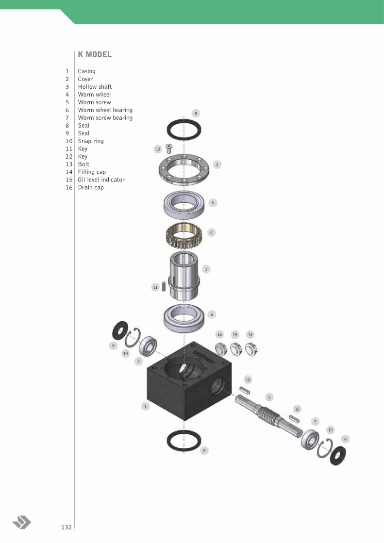
CasingsCasings are made of grey cast iron EN-GJL-250 (according to the UNI EN 1561: 1998 requirements), theyhave a parallelepiped form, with six completely end finished faces, and having a varnished inner part.
Worm screwsFor the entire K series, worm screws are made of a special steel 16NiCr4 (according to the UNI EN10084:2000 requirements).They undergo thermal treatments like case-hardening and carburizing beforebeing thoroughly ground on both the threads and the tangs.
Worm wheel Worm wheels are made of bronze type AlSn12 (according to the UNI EN 1982:2000 requirements).Theyhave high mechanical features for non-stop running and high performances. The profile of the worm wheelstoothing has been designed especially for our screw jacks and can easily support heavy duties.
Hollow shaftThe hollow shaft is made of a special steel 16NiCr4 (according to the UNI EN 10084:2000 requirements),and it undergoes thermal treatments like case-hardening and carburizing before being thoroughly ground onall its parts.
Ball spindlesAll ball spindles available in the market can be mounted on the K series. The mounting system versatilityallows to only use three screw jack sizes to cover a range of ball spindles from the 16x5 to the 80x20 one.UNIMEC is able to supply screw jacks equipped with ball spindles of any kind of supplier.
ProtectionsProtection can also be applied in order to prevent dust and foreign matters from coming into contact withthe coupling and causing damages to the ball spindle and its support nut. For KT models, a steel rigid pipecan be provided on the back side, while the front side can be protected by polyester and PVC elastic bellows.In KR models only elastic protections can be applied.
Bearings and market materialsTop-quality bearings and market materials are used for the whole line.
Weight (as referred to the basic models)
Weight [kg] 15 41 64
Size 59 88 117
126
B a l l s c r e w j a c k s
GLOSSARY
A = maximum angular speed of the worm screw [rpm]B = load cycle frequency [Hz]C = unit load to be handled [daN]Ce = equivalent unit load [daN]Frv = radial forces on the worm screw [daN]fa = ambient factorfd = duration factorfg = usage factorJ = total inertia [kgm2]Jk = screw jack inertia [kgm2]Jv = inertia downstream of the screw jack [kgm2]Mfv = braking torque on the worm screw [daNm]Mtc = hollow shaft torque [daNm]Mtv = torque on the worm screw [daNm]n = number of screw jacks under a single handlingPi = input power to the single screw jack [kW]Pe = equivalent power [kW]Pei = input equivalent power to the single screw jack [kW]PJ = inertia power [kW]PTC = adjustment factor on thermal powerT = tangential component of the contact forces between the worm wheel and the worm
screw (with reference to the worm wheel), [daN]rpm = rounds per minutev = axial translation speed of the load [mm/min]ηa = ball spindle running efficiencyηk = K screw jack running efficiencyωc = hollow shaft angular speed [rpm]ωv = worm screw angular speed [rpm]αv = worm screw angular acceleration [rad/s2]
Unless otherwise specified all dimension tables show linear measurements expressed in [mm].All the reduction ratios are expressed in the form of a fraction, unless otherwise specified.
com
pone
nts
spec
ifica
tions
and
glo
ssar
y
127
LOAD ANALYSIS AND COMPOSITION
For the definition, the analysis and the features of the different load types, see the relative paragraph in thetrapezoidal screw jack section, on page 28.
BACKLASH
Backlash on the worm screwThe worm screw – worm wheel coupling has a small degree backlash. Under the effect of the reduction ratioand of the transformation from the rotation movement to the translation movement, this backlash becomesan error in the linear positioning of a few hundredths of a millimetre, according to the diameter and pitch ofthe ball spindle. For all other backlashes (lateral and axial) between the spindle and the lead nut it isnecessary to refer to the ball spindle manufacturers catalogues.
RUNNING EFFICIENCY
As a ball screw jack is used to handle loads having high percentage of service, it is necessary that its runningefficiency be the maximum possible, in order to minimize the losses of the energy transformed into heat. Themeshes precision allows to have a couplings running efficiency higher than 90%.The total running efficiencyof the transmission, due to the lubrication splash and to the sliding of the rotating parts, like bearings andshafts, reaches values towards 85%.
HANDLING
Manual and motorized operationThe K series only presents one ratio for all three sizes: an exact 1/5.This allows a great deal of precision inthe couplings. All the K series can be manually or motor operated. As a standard production, for the IECunified motors, it is possible to connect them directly to screw jacks. Special flanges can be made forhydraulic motors, pneumatic motors, brushless motors, as well as for direct current motors, permanentmagnet motors, stepper motors and other special motors. In the case where it is not possible to motorize ascrew jack directly, a connection by means of an housing and a joint can be foreseen. The power tablesdetermine, in case of unit service factors and for every single screw jack, the moving power and the inputtorque according to the size and the requested output torque.
Rotation directionsIn standard conditions UNIMEC supplies K series screw jacks equipped with right-handed worm screw, towhich correspond the movements illustrated in the drawings below.
Emergency operationIn case of black-out, in order to be able to manually operate the single screw jacks or the complete structuresby means of a crank, a free end on the screw jack worm screw or on the transmission is to be foreseen. Incase of self-braking motors or worm screw motor reducers, the brake must be firstly released and then it isnecessary to disassemble those components from the transmission as the reducer could also be irreversible.Attention: it is advisable to equip the emergency operation mechanism with a safety device to cut the electriccircuit.
128
runn
ing
effic
ienc
y,ha
ndlin
g an
d lu
bric
atio
n
LUBRICATION
Inner lubrication The lubrication of the inner transmission devices to the casing is made, in the series production, using asynthetic oil having marked tribologic characteristics:TOTAL CARTER SY 320.The technical specificationsand the application field for the lubricant inside the casing are shown below.
* for operating temperatures between 80°C and 150°C Viton® seals should be used; for temperatures higher than 150°Cand lower than -20°C it is advisable to contact our technical office.
A filling cap, a drain cap and an oil level indicator are foreseen for all sizes.Those three caps are diagonallyarranged on one face of the casing.The intermediate cap is the level indicator, while the upper one is the fillingcap and the lower one is the drain cap, as showed in the drawing below.The quantity of lubricant containedin the K series screw jacks is indicated in the following table.
Ball spindleThe end user is responsible for the lubrication of the ball spindle which must be carried out using a lubricantsuggested by the manufacturer. Lubricating the ball spindle is an important and determining factor for theproper functioning of the screw jack. It must be carried out at regular intervals that can assure a constantcoat of clean lubricant between the contact parts. Insufficient lubrication, or an improper lubrication canlead to abnormal overheating and consequent wear phenomena, which naturally reduce the operating life ofthe screw jacks. In case the screw jacks are not visible or the ball spindles are covered by protections it isnecessary to periodically verify the lubrication conditions.
Semi - automatic lubricationMany different systems of automatic lubrication are feasible, like for example an oil bath rigid protection(with a recirculation option) on KT model screw jacks with vertical mounting (see page 153).
Centralized lubricationMany automatic lubrication systems with a central pump and various distribution points are also possible.The quantity of lubricant required depends on the service and work environment. A centralized dosing systemdoes not exclude a periodic check of the lubrication conditions in the ball spindle.
Lubricant Application field Operating temperature [°C]* Technical specifications
Total Carter SY 320 standard -20 : +200 DIN 51517-3: CLP(not compatible with PAO based NF ISO 6743-6: CKS/CKTmineral and synthetic oils)
Total Nevastane SY 320 food industry -20 : +250 NSF-USDA: H1(not compatible with PAO based
mineral and synthetic oils)
129
INSTALLATION AND MAINTENANCE
InstallationWhen arranging the ball screw jack and coupling it to machines, pay attention to the axis alignment. Failingan exact alignment, the bearings would be subjected to a greater overloading and anomalous overheating aswell as to a greater wear, with a consequent reduction of their operating life. It is important to check thatthe spindle and the casing mounting plane be orthogonal and that the load and the spindle be on the sameaxis.Employing multiple screw jacks to handle the same load (see the mounting schemes section) requires furtherverifications: it is critical that the load support points, (the end fittings for KT models and the lead nuts forKR models), be perfectly aligned in order that the load can be uniformly distributed; otherwise the misalignedscrew jacks would act as brake or counter-load. Whenever several jacks have to be connected by means oftransmission shafts, it is recommended that they be perfectly aligned in order to avoid overloading the wormscrews.It is advisable to use joints capable of absorbing alignment errors without loosing the torsion strengthnecessary to keep the synchronization of the transmission. It is necessary to mount the transmission in a wayto avoid any displacement or vibrations, keeping attention to the fixing by means of bolts or tie rods. Beforeassembling the connection parts it is necessary to properly clean the contact surfaces in order to avoid anyseizing and oxidizing problems.Assembly or disassembly shall occur by means of tie rods or extractors, using the threaded hole on the shaftend. In case of forced couplings , a shrink-fitting is recommended with a temperature up to 80-100°C.Installations environments with dust, water, vapors, etc. require precautions to protect the ball spindle, suchas elastic protections (bellows) and rigid protections. The above protections are also used in order to avoidany accidental human contact with the moving devices. For civil applications it is always advisable to use thesafety components.
Preparing for serviceAll UNIMEC’s screw jacks are supplied filled with long lasting lubricant which ensures a perfect lubricationof the worm gear/worm wheel group and all the inner parts.All K series screw jacks are equipped with a lubricant filling cap, a drain cap and an oil level indicator inorder to allow the filling-up of the lubricant as necessary. As clearly explained on the relative paragraph,lubrication of the ball spindle is a user’s responsibility and it must be carried out periodically depending onthe service conditions and the operating environment. Special sealing systems allow to hold the screw jacksin any position without creating leakage problems. The application of some accessories can limit theseassembly possibilities: the various solutions to be adopted will be explained in the relevant paragraphs.Some screw jacks are equipped with an “add oil” label.The installer shall carry out the necessary oil fillingwhen gears are not working. Fillings should not be excessive in order to avoid any overheating, noise, innerpressure increase and power loss problems.
Start-upAll screw jacks undergo a careful quality examination before being delivered to the client, and are dynamicallytested load-free. When starting-up a machine where screw jacks are installed, it is critical to check for thelubrication of the ball spindles and for the absence of foreign material. During the calibration of the electricalend-of-stroke systems, the inertia of the moving masses should be taken into account, which for vertical loadswill be lower in ascent and greater in descent. Some hours of operation at full load are necessary before thescrew jack reaches its maximum running efficiency. The screw jacks can be placed under a full loadimmediately if necessary. If some circumstances, it is nonetheless advisable to operate the screw jack underincreasing loads, reaching maximum load after 20-30 hours of operation. It is likewise recommended to takedue precautions to avoid overloads in the initial stages of operation.There may be a higher temperature duringthese initial stages but this will be reduced once the screw jacks is completely run in.
130
Routine maintenanceScrew jacks must be periodically inspected, depending on the level of use and work conditions. It is advisableto check for losses of lubricant from the casing, and if this occurs, it is necessary to find and eliminate thecause and fill the lubricant up the correct level.The lubrication conditions of the ball spindle must be periodically inspected (and restored if necessary) aswell as the presence of any foreign material. All safety devices should be verified according to the normativein force.
StorageThe screw jacks must be protected from deposits of dust and foreign matter during storage. Particularattention must be paid to saline or corrosive atmospheres.We also recommend to:
- periodically rotate the worm screw to ensure proper lubrication of inner parts and avoid that the seals dry up, therefore causing lubricant losses.
- lubricate and protect the threaded spindle, the worm screw and the non varnished components- support the ball spindle in case of horizontal storage.
WarrantyThe warranty is valid only if the instructions contained in our manual are carefully followed.
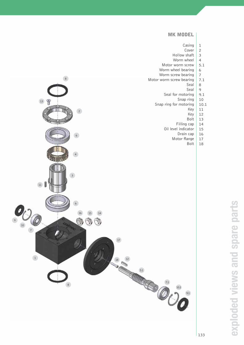
Motor worm screw Worm wheel bearingWorm screw bearing
Motor worm screw bearingSealSeal
Seal for motoringSnap ring
Snap ring for motoringKeyKeyBolt
Filling cap Oil level indicator
Drain capMotor flange
Bolt
12345.1677.1899.11010.11112131415161718
expl
oded
vie
ws
and
spar
e pa
rts
8
13
2
6
4
3
6
16 15 14
9
10
7
1
8
17
1218
5.1
9.1
7.1
10.1
11
133
negative
negative
negative
negative
negative
negative
Calculation of the unit load (B)
Calculation of the equivalent load (D)
Calculation of inertia power (E)
Verification at the equivalent power (F)
Verification at thermal power (G)
Verification at the torque (H)
Verification at the radial loads (I)
Verification of the ball spindle (J)
end
Definition of the application data (A)
Positive
Positive
Positive
Positive
Positive
Positive
Change ball screw type or geometry
Change the size or mounting scheme
Verification at static load (C)
DIMENSIONING OF THE BALL SCREW JACK
For a correct dimensioning of the ball screw jack it is necessary to observe the following steps:
134
A – THE APPLICATION DATAFor a right dimensioning of the screw jacks it is necessary to identify the application data:LOAD [daN] = the load is identified with the force applied to the translating device of a screw jack. Normallythe dimensioning is calculated considering the maximum applicable load (worst case). It is important toconsider the load as a vector, which is defined by a modulus, a direction and a sense, the modulus quantifiesthe force, the direction orients spatially and gives indications on the eccentricity or on possible lateral loads,the sense identifies the traction or compression load.TRANSLATION SPEED [mm/min] = the translation speed is the load handling speed. From this speed it ispossible to calculate the rotation speed of the rotating devices and the necessary power for the movement.Wear phenomena and the life of the screw jack proportionally depend on the value of the translation speed.STROKE [mm] = it is the linear measure used to handle a load. It does not always coincide with the totallength of the ball spindle.AMBIENT VARIABLES = these values identify the environment and the operating conditions of the screwjack. Among them: temperature, oxidizing and corrosive factors, working and non-working periods, vibrations,maintenance and cleaning, insertion frequency, foreseen operating life etc.MOUNTING SCHEMES = There are several ways of handling a load by means of screw jacks.The schemeson pages 162-163 will show you some examples. Choosing a mounting scheme will condition the choice ofthe size and the power which is necessary for the application.
B – THE UNIT LOAD According to the n number of screw jacks contained in the mounting scheme it is possible to calculate each screwjack’s load dividing the total load by n In case the load is not fairly distributed in all screw jacks, it is recommendedto consider the transmission having the heaviest load, by virtue of a dimensioning based on the worst case.
C – THE STATIC LOADAs very first step for the verification of the ball screw jack body, it’s important verify the internal componentsresistance.The following table gives, entering with the static load C and the geometry of the ball screw (diameterand pitch), the admissible jack sizes. If a certain size is in a colored area, it means that such application cangenerate internal strength whose values are next to the bearings or gears limit ones; it’s suggested to choose thehigher size.If a jack body can sustain a determined static load C, it’s not automatically true that the ball spindle can sustainthat load. It’s necessary a ball screw verification following the builder’s rules (point J).If a jack body can sustain a determined static load C, it’s not automatically true that the body can sustain thatload in dynamic conditions. It’s necessary to verify the equivalent power (point F).
dim
ensi
onin
g
Static load C [daN]Ball screw 1500 2000 3000 5000 8000 10000 15000 20000 30000(diameter x pitch)
* This spindle size can be assembled only on KR models. For KT application please contact our technical office135
D – THE EQUIVALENT LOADAll the values listed in the catalogue refer to a standard use conditions, i.e. under a temperature of 20° and aregular daily operation of 8 hours without shocks. Using the screw jack under the above conditions you canforesee a 10.000 hours lifetime (with a working percentage of 70%).For different application conditions the equivalent load should be calculated: it refers to the load which wouldbe applied in standard conditions in order to have the same thermal exchange and wear effects, which the realload achieves in the real conditions of use.It is therefore advisable to calculate the equivalent load according to the following formula:
Ce = C•fg•fa•fd
The usage factor fgBy means of the following diagram the fu use factor can be calculated according to the daily working hours.
The ambient factor faBy means of the following table it is possible to calculate the fa factor according to the operation conditions.
The duration factor fdThe duration factor fd is calculated as a function of the theoretical foreseen lifetime (expressed in hours)
E – THE INERTIA POWERIn case of high accelerations and decelerations it is necessary to calculate the inertia power PJ. It is the powernecessary to support the inertia forces and torques opposed by the system in presence of a speed change.First the designer should calculate the system inertia downstream of the screw jack Jv by reducing them firstto the hollow shaft (on which is mounted the ball screw), and then to the worm screw (input shaft). The Jvinertias are the system inertias (typically masses) as well as the ball spindle and lead nut inertias.After that, it is necessary to add the inertia of the screw jack Jk, obtainable from the tables below, in order tohave the value of the total inertia J reduced to worm screw. We remind that inertia is expressed by [kg•m2].
Given ωv the input rotation speed and αv the input angular speed the inertia torque applied is equal to J•ωvand the respective inertia power PJ is equal to J•ωv•αv. If the time changes of the input speed ωv can bereferred to one of the linear of sinusoidal schemes below, where A is the maximum speed in [rpm] and B isthe cycle frequency in [Hz], it is possible to simplify the inertia power calculation in [kW], by identifying Aand B parameters and by calculating:
F – THE EQUIVALENT POWEROnce the equivalent load Ce is calculated, it’s possible to verify the equivalent power (out the jack-ball spindlesystem) as Pe=Ce•v, where v is the load translation speed. Dividing the equivalent power on the ball screw efficiencyηa (this is a ball screw builder’s data) and on the jack efficiency ηk and adding this value to the inertia power PJ,
the equivalent input power Pei is obtained.
The very first selection of a ball screw jack body is by the power tables (see pag. 140), choosing the size that, at adetermined rotating input or output speed, presents an input power Pi higher than Pei. If this value is a colored area, itmeans that the life of the components or the thermal exchange is not sufficient;It’s suggested to change size, to low designrequirements or ask to our technical office more a more precise calculation.The equivalent power is not the power requested by the single screw jack, unless the three correction factors fg, fd andfa have a unit value.Please note that, once translation speed v is fixed, the ball screw choice must not cause an input rotation speed higherthan 3000 rpm. The following table reports the maximum translation speed in function of the ball screw pitch.
G – THE THERMAL POWER When the input speed values in the power tables cross a coloured area, this means that it is necessary to checkthe thermal power.This dimension, which is a function of the screw jack size and of the ambient temperature,indicates the input power establishing a thermal equilibrium with the environment with the screw jack surfacetemperature of 90 °C.The following graphs show the thermal power curves for the three sizes of the K series.
In case of non-working times of the screw jack, the thermal power can be increased of a PTC factorobtainable from the graph below, where the abscissa is the percentage of use as referred to the hour.
If thermal power was lower than the requested power Pi, it would be necessary to change the screw jack size.
H – THE TORQUEWhen screw jacks are serially assembled , as shown in the drawings below, it is necessary to check that thetorque moment referred to the common axis does not exceed the value indicated in the following table.
I – RADIAL LOADS In the case of radial loads on the worm screw it is necessary to check its strength according to the followingtable. In case the above values be exceeded it will be necessary to choose a higher size:
J – VERIFICATION OF THE BALL SPINDLEThe final step for the ball screw jack dimensioning is to check the chosen spindle. All the above describedsteps refer to a single screw jack capacity. According to the geometry, the construction characteristics, theused materials and the ball spindle manufacturer specifications it is necessary to check for this componentto resist to the static and dynamic load, to successfully undergo the Euler verifications, to be able to supportlateral loads, to be able to complete the requested duty cycles without overheating or having difficulties, andto check anything else the project may require.
Size 59 88 117
Frv [daN] 45 60 90
Size 59 88 117Maximum torque moment Mtv [daNm] 31,4 61,3 106
dim
ensi
onin
g
139
POWER TABLES
Load [daN] 4000 2000 1000 700 500 100 50
Size 59
Spinde Pi [kW] Pi [kW] Pi [kW] Pi [kW] Pi [kW] Pi [kW] Pi [kW]translationspeed [mm/min]24000 - - 6,77 4,73 3,50 0,70 0,3520000 - - 5,64 3,94 2,81 0,56 0,2815000 - - 4,22 2,95 2,11 0,42 0,2110000 - 5,73 2,84 1,97 1,41 0,28 0,145000 - 2,92 1,44 1,00 0,71 0,14 0,071000 1,24 0,63 0,30 0,21 0,15 0,07 0,07500 0,70 0,32 0,15 0,11 0,07 0,07 0,07
Load [daN] 7500 5000 4000 2000 1000 500 200
Size 88
Spinde Pi [kW] Pi [kW] Pi [kW] Pi [kW] Pi [kW] Pi [kW] Pi [kW]translationspeed [mm/min]24000 - - - - 6,67 3,34 1,3320000 - - - - 5,61 2,80 1,1215000 - - - 8,47 4,17 2,09 0,8310000 - - - 5,70 2,80 1,40 0,565000 - - 5,85 2,91 1,44 0,71 0,281000 2,30 1,56 1,22 0,62 0,30 0,15 0,07500 1,20 0,78 0,63 0,32 0,15 0,08 0,07
THE BREAKING COUPLEBall screw jacks are reversible transmissions. In order to maintain load in a determined position, it’snecessary to apply a breaking couple on the worm screw, whose values in [daNm] are reported in the tablebelow in function of the load and of the ball screw pitch.
KT ModelsMounting the ball lead nuts on the KT models depends on their geometry (cylindrical or with flanges) andon their diameter (whether smaller, equal or greater than the hollow shaft diameter D, in detail 48, 72 and105 mm, respectively for sizes 59, 88 and 117).
a) CYLINDRICAL LEAD NUT WITH DIAMETER = DOnce inserted the lead nut must be blocked by means of shoulder flanges, as per drawing below.
Size 59 88 117
For not quoted dimensions see the schemes on page 147.
D Ø g6 48 72 105D3 Ø 59 90 124D6 Ø 72 110 150F7 Ø (6 holes) 7 11 13G 118 148 174D7 Dimension function of the lead nut to be appliedL1 Dimension function of the lead nut to be appliedL2 Dimension function of the lead nut to be appliedL3 Dimension function of the lead nut to be applied
142
b) CYLINDRICAL LEAD NUT WITH DIAMETER < DThe nut must be inserted into a reduction sleeve and blocked by means of a snap ring.The sleeve passesthrough the hollow shaft.The drawing below will show the mounting geometry.
c) CYLINDRICAL LEAD NUT WITH DIAMETER > DMounting: not possible.
Size 59 88 117
D Ø g6 48 72 105D3 Ø 59 90 124D6 Ø 72 110 150F7 Ø (6 holes) 7 11 13D7 Dimension function of the lead nut to be appliedL1 Dimension function of the lead nut to be appliedL2 Dimension function of the lead nut to be appliedL3 Dimension function of the lead nut to be appliedL4 Dimension function of the lead nut to be appliedL5 Dimension function of the lead nut to be appliedN Dimension function of the lead nut to be applied
For not quoted dimensions see the schemes on page 147.
KT m
odel
s
143
d) FLANGED LEAD NUT WITH DIAMETER = DThe lead nut can be directly mounted on the hollow shaft if the holes position coincide.The drawing belowwill show the mounting geometry.
Size 59 88 117
D Ø 48 72 105D3 Ø 59 90 124G 118 148 174F7 Ø (6 holes) Dimension function of the lead nut to be appliedD6 Ø Dimension function of the lead nut to be appliedL1 Dimension function of the lead nut to be appliedL2 Dimension function of the lead nut to be appliedL3 Dimension function of the lead nut to be applied
For not quoted dimensions see the schemes on page 147.
144
e) FLANGED LEAD NUT WITH DIAMETER < DThe lead nut must be mounted on a reduction flange connected to the hollow shaft.The drawing below willshow the mounting geometry.
f) FLANGED LEAD NUT WITH DIAMETER > DMounting: not possible
Size 59 88 117
D Ø g6 48 72 105D3 Ø 59 90 124D6 Ø 75 115 150F7 Ø (6 holes) M6 M10 M12D7 Dimension function of the lead nut to be appliedD8 Dimension function of the lead nut to be appliedL1 Dimension function of the lead nut to be appliedL2 Dimension function of the lead nut to be appliedL3 Dimension function of the lead nut to be appliedF8 Dimension function of the lead nut to be applied
For not quoted dimensions see the schemes on page 147.
KT m
odel
145
KR MODELSMounting the ball spindles and lead nuts in the KR models depends on the spindle diameter.This diameter mustbe smaller than the hollow shaft diameter D (in detail 48, 72 and 105 mm, respectively for sizes 59, 88 and117) in order to allow mounting a sleeve for rotating screw as highlighted in the drawing below.
KR ModelsSize 59 88 117D Ø g6 48 72 105D3 Ø 59 90 124D6 Ø 72 110 150F7 Ø (6 holes) 7 11 13D7 Ø Dimension function of the lead nut to be appliedL1 Dimension function of the lead nut to be appliedL2 Dimension function of the lead nut to be appliedL3 Dimension function of the lead nut to be appliedN Dimension function of the lead nut to be applied
For not quoted dimensions see the schemes on page 147.
For not quoted dimensions see the schemes on page 147.
148
GR rotating guideThe rotating guide is a bronze flange applied, for KT models, on the hollow shaft on the opposite side to thelead nut.The guide rotates together with the hollow shaft and gives a valid support in the absorption of lateralloads and in maintaining the spindle translation in the same axis as the worm wheel.The GR can be appliedonly to KT models.The overall dimensions are indicated in the table below.Incompatibility: KR models
GR rotating guideSize 59 88 117D Ø g6 48 72 105D3 Ø 59 90 124D6 Ø 75 115 150F7 Ø (6 holes) 7 11 13D7 Dimension function of the lead nut to be appliedL1 Dimension function of the lead nut to be appliedL2 Dimension function of the lead nut to be appliedL3 Dimension function of the lead nut to be applied
For not quoted dimensions see the schemes on page 147.
MK
mod
el a
nd a
cces
oire
s
149
GSI lower static guideThe lower static guide is a bronze and steel flange applied, for KT models, on the casing in the lower part ofthe screw jack. Being connected with the casing, the guide is static and gives a valid support in the absorptionof lateral loads and in maintaining the spindle translation in the same axis as the worm wheel.The GSI canbe applied only to KT models.The overall dimensions are indicated in the table below.Incompatibility: KR models - PR
GSI lower static guideSize 59 88 117D1 Ø g6 85 130 170D4 Ø 96 143 182D22 Ø 110 160 200F4 Ø (4 holes) 7 7 7G4 3 3 3D7 Ø Dimension function of the lead nut to be appliedD23 Ø Dimension function of the lead nut to be appliedL1 Dimension function of the lead nut to be appliedL3 Dimension function of the lead nut to be appliedL4 Dimension function of the lead nut to be appliedL5 Dimension function of the lead nut to be applied
For not quoted dimensions see the schemes on page 147.
150
GSS upper static guideThe upper static guide is a bronze and steel flange applied, for KT models, on the casing in the upper part ofthe screw jack. Being connected with the casing, the guide is static and gives a valid support in the absorptionof lateral loads and in maintaining the spindle translation in the same axis as the worm wheel.The GSS canbe applied only to KT models.The overall dimensions are indicated in the table below.Incompatibility: KR models
GSS upper static guideSize 59 88 117D1 Ø g6 85 130 170D4 Ø 96 143 182D22 Ø 110 160 200F4 Ø (4 holes) 7 7 7G4 3 3 3D7 Dimension function of the lead nut to be appliedD23 Ø Dimension function of the lead nut to be appliedL1 Dimension function of the lead nut to be appliedL3 Dimension function of the lead nut to be appliedL4 Dimension function of the lead nut to be appliedL5 Dimension function of the lead nut to be appliedL6 Dimension function of the lead nut to be applied
For not quoted dimensions see the schemes on page 147.
acce
ssor
ies
151
PR rigid protectionThe application of a rigid protection in the back side of the screw jack is the ideal solution in order to preventdust and foreign matters from coming into contact with the coupling and causing damages to the ball spindle.The PR protection can only be applied to KT models. In the following table the overall dimensions are shown.Incompatibility: KR models - GSI - SP
For not quoted dimensions see the schemes on page 147.
S7+
str
oke
S8
152
Protection rigide à bain d'huile PROL’application de la protection rigide à bain d'huile, outre à assumer la fonction de protection rigide, permetde bénéficier des avantages d'une lubrification semi-automatique. Au montage, en position refermé, il fautremplir la protection de lubrifiant à l'aide du bouchon de remplissage. A chaque manoeuvre, la vis àrecirculation de billes s'imprègne de lubrifiant. Nous rappelons que la zone indiquée sur le dessin peutprésenter des écoulements de lubrifiant: il faut donc effectuer un montage qui ne permette pas de pertes.La PRO n'est applicable qu'aux modèles KT. Le tableau ci-dessous indique les dimensions d'encombrement.Incompatibilité: modèles KR – GSI – SP
For not quoted dimensions see the schemes on page 147.
S7+
str
oke
S8
PRO oil bath rigid protectionThe application of an oil bath rigid protection, apart from representing a rigid protection, also allows to havethe advantages of a semi-automatic lubrication.The lubricant must be added when mounting with the jackcompletely closed, using the oil fill cap. Upon manoeuvring, the ball spindle will be soaked with lubricant.In case the spindle is left out of the protection for a long period, it could dry up so to make the PROprotection useless. For long strokes, in order to compensate the pump effect, it is necessary to mount an oilrecirculation pipe allowing lubricant to flow back inside the protection from the casing. Alternatively, it ispossible to assemble the casing and the protection in a single chamber. We remind you that the areaindicated in the drawing could present lubricant drops: a vertical mounting will therefore avoid any leakageproblems.The PRO protection can only be applied to KT models. In the following table the overall dimensionsare shown.Incompatibility: KR models - GSI - SP
acce
ssor
iac
cess
orie
s
153
stro
ke
PE elastic protectionThe purpose of the elastic protections is to protect the ball spindle by following its own movement during stroke.Standard type protections are elastic bellows,made of polyester covered nylon and ending with a flange from the screwjack side and with a collar from the end fitting side, whose dimensions are shown in table 1 below. Specialimplementations are available upon request, as well as a fixing by means of iron. Fixing flanges can be in plastic ormetal.Special materials for the bellows are also available:Neoprene® and Hypalon® (water sea environment),Kevlar®
(resistant to cuts and abrasion), glass fiber (for extreme temperatures, from -50 to 250 °C) e aluminized carbon (it’san auto-extinguish material for limit applications with molten metal spits). The PE standard material is guaranteefor ambient temperature between -30 and 70 °C. If it’s needed a waterproof elastic bellow, it’s possible to realizeprotections whose bellows are not sewed but heat-sealed. This kind of protection is not able to solve condensateproblem.Moreover, it’s possible to have metal protections on demand; such requests are be submitted to the TechnicalOffice.. Besides further implementations made of special materials fire-resistant, cold-resistant and suited foraggressive oxidizing environments can be supplied. In case of long strokes internal anti-stretching rings are previewedin order to guarantee an uniform bellows opening.
Table 1
The application of elastic protections on the screw jacks may implicate some dimensioning amendments due to the PEown sizes, as shown in table 2. Further, in completely close conditions, the PE has an overall dimension equal to 1/8of the stroke value. In case of horizontal mounting (of which previous notice should be given) it is necessary tosupport the protection weight in order to avoid that it leans on the ball spindle; for this purpose special support ringsare foreseen.The PE can be applied to KT and KR models and in case of missing specifications they can be suppliedwith a fabric collar at the end fitting and the dimensions shown in table 1.Incompatibility: none
PE elastic protectionSize 59 88 117A Ø 85 120 140D4 Ø 96 143 182F4 Ø (4 holes) 7 7 7L 1/8 of the stroke (all closed)D screw Ø Dimension function of the spindle to be appliedC Ø Dimension function of the end fittingH1 Ø Dimension function of the spindle to be appliedL1 Dimension function of the spindle to be applied
stro
ke
154
Table 2
PRF stroke controlIn order to meet the requirement of an electric stroke control, it is possible to apply to a rigid protectionsuitable end-of-stroke supports. In the standard version these supports are of two types and they are placedat the ends of the stroke in one of the four positions shown below. They are carried out in such a way as toallow a small adjustment. In case more than one end-of-stroke are needed, it is possible to provideintermediate supports or a continuous support for the requested length. In order to enable the end-of-stroketo operate, a steel bushing is mounted on the ball spindle. More bushings can be mounted upon request.ThePRF can only be applied to KT models and in case of missing specifications it will be supplied with thesupports mounted according to position 1. Moreover it’s possible assembling magnetic sensors on theprotection, avoiding to mill it. The end-of-stroke signal is given by a magnet attached on the bottom of thespindle.The overall dimensions are shown in the table below.Incompatibility: KR – PRO models - GSI - SP
For not quoted dimensions see the schemes on page 147.
PE elastic protectionSize 59 88 117S3 8 12 15D1 Ø 85 120 140L1 1/8 of the stroke (all closed)
For not quoted dimensions see the schemes on page 147.
stro
ke
acce
ssor
ies
155
PRA double guide anti rotationAs all screw jacks must have an anti-rotation, in case such constraint cannot be realized externally, it ispossible, for KT models, to have an inner anti-rotation system inside the screw jack.Two guides are mountedon the rigid protection where a bronze bushing, which is attached to the ball spindle can slide. In case of verylong strokes, it should be checked that the torsional sliding is not such as to force the fixing screws in theguides. As the inner anti-rotation constraints the ball spindle and its end fitting, in case of presence of holes,their position should be notified, as indicated in the drawings below. Unless otherwise stated all screw jackswill be delivered in position 1 or 3. The overall dimensions are shown in the table below.Incompatibility: KR models - GSI - SP
For not quoted dimensions see the schemes on page 147.
1 2 3 4
S10
+ s
trok
e
S8
156
CR rotation controlIn some cases it can be necessary to check the operation conditions of the screw jack monitoring the wormwheel rotation, both in KT models and in KR models. A milling is carried out on the worm wheel and asuitable proximity switch supplies an electric impulse for each turn. No impulse means that the transmissionis stopped. Special executions with more impulses per round are always possible.Incompatibility: None
CT temperature control It is possible to control the casing temperature by means of a thermal probe emitting an electric impulsewhen the preset temperature of 80 °C is reached. Moreover it’s possible to apply a sensor able to catch thetemperature exact value and to send to a plc an electric signal proportional to the above mentioned value.Incompatibility: none
For not quoted dimensions reference should be made to the schemes on pages 147.ac
cess
orie
s
157
SP additional mounting platesIf for project requirements it is necessary to fix the screw jacks on holes which do not coincide with thecasing holes, steel mounting plates can be supplied.The overall dimensions for the standard version are shownin the table below, but different fixing holes can be realized upon request.Incompatibility: P – PO – PR – PRO – PRA
For not quoted dimensions see the schemes on page 147.
158
PO rigid rocking protectionWhen it is necessary to apply a rocking mounting, UNIMEC is able to offer, for KT models, a special rigidreinforced protection which has an eyelet at its end. This protection very often supports the load, and it istherefore advisable that this protection be not too long in order to avoid an anomalous bending of PO.Further it should be reminded that mounting a PO in combination with an end fitting having an eyelet doesnot automatically give to the screw jack the status of a connecting rod (absence of lateral loads). Motorscan directly be assembled to the screw jack. In case of compressive loads, the buckling verification must becalculated on a length equal to the hinges distance. In the following table the overall dimensions are shown.Incompatibility: KR - P- PR – PRO – SP
For not quoted dimensions see the schemes on page 147.
+ s
trok
e
acce
ssor
ies
159
P Lateral pinsThe purpose of this solution is very similar to the PO one: two lateral pins are fixed on the screw jack bodyin order to allow a rocking mounting. Under some aspects this solution can be preferred to the rockingprotection because, in the slender rod scheme, the distance between the two hinges is exactly half. Furtherwe remind you that mounting lateral pins combined with an end fitting having an eyelet does notautomatically give to the screw jack the status of a connecting rod (absence of lateral loads). Motors candirectly be assembled to the screw jack. In case of compressive loads, the buckling verification must becalculated on a length equal to the hinges distance. In the following table the overall dimensions are shown.Incompatibility: PO – SP
NIPLOY treatmentFor applications in oxidizing environments, it is possible to protect some screw jack components which do notundergo any sliding, by means of a chemical nickel treatment, the so-called Niploy. It creates a non permanentsurface coating on casings, covers, bushings, end fittings, and on the protruding shafts of the worm screw.Theball spindle cannot undergo this treatment.
For not quoted dimensions see the schemes on page 147.
160
NORMS
ATEX directive (94/9/CE)The 94/9/CE directive is better known as the “ATEX directive”. All UNIMEC’s products may be classifiedas “components” according to the definition quoted in art.1 par.3 c), and therefore they do not require anATEX mark.A conformity declaration in accordance to what stated in art.8 par.3 can be supplied upon end user’s request,subject to the filling up of a questionnaire with the indication of the working parameters.
Machinery directive (98/37/CE)The 98/37/CE directive is better known as the “Machinery directive”. UNIMEC’s components are includedin the products categories which do not need to affix the CE mark, as they are “intended to be incorporatedor assembled with other machinery” (art.4 par.2). Upon end user’s request a manufacturer declaration canbe supplied in accordance to what is foreseen at Annex II, point B. The new machine directory (06/42/CE)will be acknowledged by 29/12/2009. UNIMEC guarantees that every new duty in mechanical transmissionwill be followed by such date.
ROHS directive (02/95/CE)The 02/95/CE directive is better known as the “ROHS directive”. All UNIMEC’s suppliers ofelectromechanical equipments have issued a conformity certification to the above norms for their products.A copy of said certificates can be supplied upon final user’s request.
REACH directive (06/121/CE)The 06/121/CE is better is known as “REACH” directive and applies as the rule CE 1907/2006. UNIMECproducts present only inside lubricants as “substances”, so being disciplined by art. 7 of above mentionedrule. By art. 7 par. 1 b) UNIMEC declares that its products are not subjected to any declaration orregistration because the substances in them are not “to be lost in normal and reasonable previewed usageconditions”; in facts lubricant losses are typical of malfunctions or heavy anomalies. By art. 33 of the ruleCE 1907/2006, UNIMEC declares that inside its products there aren’t substances identified by art. 57 inpercentage to be dangerous.
UNI EN ISO 9001:2000 normUNIMEC has always considered the company’s quality system management as a very importantsubject. That is why, since the year 1996, UNIMEC is able to show its UNI EN ISO 9001certification, at the beginning in accordance to the 1994 norms and now meeting therequirements of the version published in the year 2000. 13 years of company’s quality, certifiedby UKAS, the world’s most accredited certification body, take shape into an organization whichis efficient at each stage of the working process. In date 31/10/2008 the new version of this norm waspublished. UNIMEC will evaluate every news reported in this revision.
PaintingOur products are all painted in color RAL 5015 blue. An oven-dry system enables the products to have aperfect adhesivity. Different colors as well as epoxidic paints are available.
acce
ssor
ies
and
norm
s
161
MOUNTING SCHEMES
Scheme 1
Scheme 2
Scheme 3
Scheme 4
162 Application samples are online at www.unimec.eu - section Applications
Scheme 5
Scheme 6
Scheme 7
mou
ntin
g sc
hem
es
163Application samples are online at www.unimec.eu - section Applications