Compressed Air Systems Instrumentation & Automated Pneumatic Controls Pneumatic Tools & Cylinders Balston High Flow, Low Pressure Drop Coalescing Compressed Air Filters n Remove 99.5% of 0.3 micron particles of oil, water, and dirt from compressed air and other gases n Extremely low pressure drop n Low operating costs n Continuously trap and drain liquids n Service flow ranges from a few scfm to 65,000 scfm n Pleated media offering long filter life Balston High Flow Capacity Filter Assemblies Balston Coalescing Compressed Air Filters protect your equipment and delicate instruments from the dirt, water, and oil usually found in compressed air. Balston Co- alescing Filters remove these contaminants at a very high efficiency - up to 99.5% for 0.3 micron particles and droplets. Liquid releases from the filter cartridge to an automatic drain as rapidly as it enters the filter. This allows the Balston coalescing filter to continue removing liquids for an unlimited time without loss of efficiency of flow capacity. In addition, this new HF media technology offers the lowest operating pressure drop performance in the industry. At only 0.25 psi (dry) and 0.5 psi (wet), the new HF media offers significant operating cost savings. Bulletin ASME-A Plant Air Systems Air Dryer Protection Critical Low Pressure Drop Source Air High Solids Contamination High Efficiency Filtration Requirement with Space Limits Applications
Transcript
� www.parker.com/balston
Compressed Air Systems Instrumentation & Automated Pneumatic Controls Pneumatic Tools & Cylinders
Balston High Flow, Low Pressure Drop Coalescing Compressed Air Filters
n Remove 99.5% of 0.3 micron particles of oil, water, and dirt from compressed air and other gases
n Extremely low pressure drop
n Low operating costs
n Continuously trap and drain liquids
n Service flow ranges from a few scfm to 65,000 scfm
n Pleated media offering long filter life
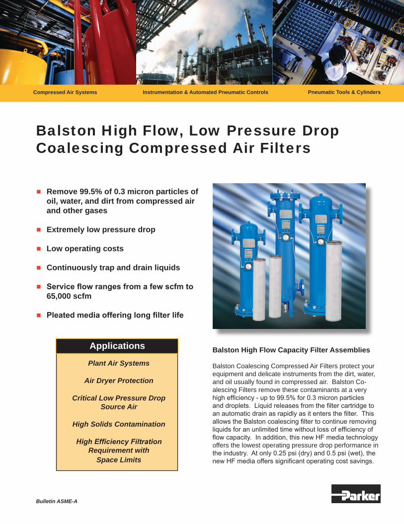
Balston High Flow Capacity Filter Assemblies Balston Coalescing Compressed Air Filters protect your equipment and delicate instruments from the dirt, water, and oil usually found in compressed air. Balston Co-alescing Filters remove these contaminants at a very high efficiency - up to 99.5% for 0.3 micron particles and droplets. Liquid releases from the filter cartridge to an automatic drain as rapidly as it enters the filter. This allows the Balston coalescing filter to continue removing liquids for an unlimited time without loss of efficiency of flow capacity. In addition, this new HF media technology offers the lowest operating pressure drop performance in the industry. At only 0.25 psi (dry) and 0.5 psi (wet), the new HF media offers significant operating cost savings.
Bulletin ASME-A
Plant Air Systems
Air Dryer Protection
Critical Low Pressure Drop Source Air
High Solids Contamination
High Efficiency FiltrationRequirement with
Space Limits
Applications
Bulletin ASME.indd 1 1/24/2007 10:21:33 AM
�-800-343-4048 �
New LF/FF Series Multiple Cartridge Filter Assemblies These filter assemblies provide high efficiency filtration of compressed air and other compressed gases at very high flow rates. With inlet and outlet ports accommodat-ing 3” to 10” pipe sizes, the new LF/FF Series housings are capable of flow rates up to a maximum capacity of 37,350 SCFM at 100 psig. The standard carbon steel units, which are generally in stock (through 6” line sizes), have pressure ratings up to 185 psig. All LF/FF series housings are ASME Code Stamped for the rated maximum operating pressure. All FF Series vessels have built-in legs for floor mounting. Selected models have swing bolt enclosures for easy access to the internals. The filter cartridges in all models are sealed by tightening the threaded retainer cap onto the rigid tie rod, ensuring a leak tight seal on both ends of the cartridge. Each assembly is equipped with an automatic float drain, differential pressure indicator, and a set of filter cartridges (except where noted).
HFC Savings Annual electricity costs to operate a 100 HP Compressor can be as high as $50,000. Pressure loss in the system adds to this expense. For a system operating at 100 psig that loses 2 psig of pressure through a filter, requires an additional 1% in operating energy costs (1). Installing a single stage HFC Filter in place of a standard brand X filter, will reduce the pressure drop by 2+ psi.Based on a standard 100 HP compressor operating at a 65% load cycle, a 1% reduction in annual operating costs would be equal to $542.00
Calculation with Part-Load Operation (100 hp compressor)
Annual Electricity Costs = [(Motor full-load brake horsepower) x (0.746 kW/hp) x (Annual Hours of Operation) x (Electricity Cost in $/kWh)] x [(Percent of time running fully loaded) + (0.30) x (Percent of time running unloaded)]For example: Full load motor efficiency = 90%Motor full load bhp = 100 hpAnnual hours of operation = 8,760 hours (3-shift, continuous operation)Runs 65% of the time fully loaded, 35% of the time unloadedUnloaded operation consumes 30 percent of the electricity of fully loaded operationCost of electricity = $0.10/kWhAnnual electricity costs = [(100 hp) x (0.746 hp/kW) x (8,760 hrs) x $0.10/kWh) / 0.9] x [0.65 + (0.30) x (0.35)] = $54,272.00
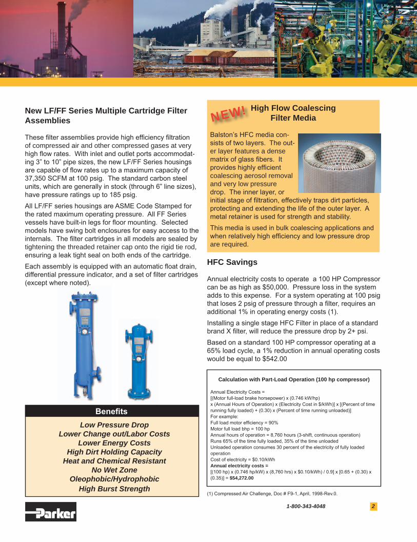
High Flow Coalescing Filter Media
Balston’s HFC media con-sists of two layers. The out-er layer features a dense matrix of glass fibers. It provides highly efficient coalescing aerosol removal and very low pressure drop. The inner layer, or initial stage of filtration, effectively traps dirt particles, protecting and extending the life of the outer layer. A metal retainer is used for strength and stability.This media is used in bulk coalescing applications and when relatively high efficiency and low pressure drop are required.
NEW!
Low Pressure DropLower Change out/Labor Costs
Lower Energy CostsHigh Dirt Holding Capacity
Heat and Chemical ResistantNo Wet Zone
Oleophobic/HydrophobicHigh Burst Strength
Benefits
(1) Compressed Air Challenge, Doc # F9-1, April, 1998-Rev.0.
Bulletin ASME.indd 2 1/24/2007 10:21:47 AM
3 www.parker.com/balston
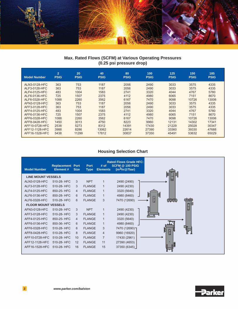
Max. Rated Flows (SCFM) at Various Operating Pressures(0.25 psi pressure drop)
Housing Selection Chart
2 20 40 80 100 125 150 185 Model Number PSIG PSIG PSIG PSIG PSIG PSIG PSIG PSIG